JP6873011B2 - Substrate processing equipment and substrate processing method - Google Patents
Substrate processing equipment and substrate processing method Download PDFInfo
- Publication number
- JP6873011B2 JP6873011B2 JP2017165379A JP2017165379A JP6873011B2 JP 6873011 B2 JP6873011 B2 JP 6873011B2 JP 2017165379 A JP2017165379 A JP 2017165379A JP 2017165379 A JP2017165379 A JP 2017165379A JP 6873011 B2 JP6873011 B2 JP 6873011B2
- Authority
- JP
- Japan
- Prior art keywords
- substrate
- coating liquid
- speed
- period
- rate
- Prior art date
- Legal status (The legal status is an assumption and is not a legal conclusion. Google has not performed a legal analysis and makes no representation as to the accuracy of the status listed.)
- Active
Links
- 239000000758 substrate Substances 0.000 title claims description 382
- 238000003672 processing method Methods 0.000 title claims description 12
- 239000007788 liquid Substances 0.000 claims description 407
- 239000011248 coating agent Substances 0.000 claims description 219
- 238000000576 coating method Methods 0.000 claims description 219
- 238000007599 discharging Methods 0.000 claims description 16
- 239000002904 solvent Substances 0.000 description 44
- 230000002093 peripheral effect Effects 0.000 description 12
- 238000000034 method Methods 0.000 description 11
- 238000001035 drying Methods 0.000 description 8
- 238000004140 cleaning Methods 0.000 description 7
- 230000000052 comparative effect Effects 0.000 description 6
- 238000010586 diagram Methods 0.000 description 6
- 230000015572 biosynthetic process Effects 0.000 description 3
- 238000003860 storage Methods 0.000 description 3
- 238000009736 wetting Methods 0.000 description 3
- ARXJGSRGQADJSQ-UHFFFAOYSA-N 1-methoxypropan-2-ol Chemical compound COCC(C)O ARXJGSRGQADJSQ-UHFFFAOYSA-N 0.000 description 2
- JHIVVAPYMSGYDF-UHFFFAOYSA-N cyclohexanone Chemical compound O=C1CCCCC1 JHIVVAPYMSGYDF-UHFFFAOYSA-N 0.000 description 2
- 230000000694 effects Effects 0.000 description 2
- 238000004519 manufacturing process Methods 0.000 description 2
- LLHKCFNBLRBOGN-UHFFFAOYSA-N propylene glycol methyl ether acetate Chemical compound COCC(C)OC(C)=O LLHKCFNBLRBOGN-UHFFFAOYSA-N 0.000 description 2
- 239000004065 semiconductor Substances 0.000 description 2
- 238000005406 washing Methods 0.000 description 2
- 238000004590 computer program Methods 0.000 description 1
- 230000006870 function Effects 0.000 description 1
- 230000010354 integration Effects 0.000 description 1
- 239000011229 interlayer Substances 0.000 description 1
- 238000001459 lithography Methods 0.000 description 1
- 238000000206 photolithography Methods 0.000 description 1
- 239000002699 waste material Substances 0.000 description 1
Images


Classifications
-
- H—ELECTRICITY
- H01—ELECTRIC ELEMENTS
- H01L—SEMICONDUCTOR DEVICES NOT COVERED BY CLASS H10
- H01L21/00—Processes or apparatus adapted for the manufacture or treatment of semiconductor or solid state devices or of parts thereof
- H01L21/67—Apparatus specially adapted for handling semiconductor or electric solid state devices during manufacture or treatment thereof; Apparatus specially adapted for handling wafers during manufacture or treatment of semiconductor or electric solid state devices or components ; Apparatus not specifically provided for elsewhere
- H01L21/67005—Apparatus not specifically provided for elsewhere
- H01L21/67011—Apparatus for manufacture or treatment
- H01L21/6715—Apparatus for applying a liquid, a resin, an ink or the like
-
- B—PERFORMING OPERATIONS; TRANSPORTING
- B05—SPRAYING OR ATOMISING IN GENERAL; APPLYING FLUENT MATERIALS TO SURFACES, IN GENERAL
- B05C—APPARATUS FOR APPLYING FLUENT MATERIALS TO SURFACES, IN GENERAL
- B05C11/00—Component parts, details or accessories not specifically provided for in groups B05C1/00 - B05C9/00
- B05C11/02—Apparatus for spreading or distributing liquids or other fluent materials already applied to a surface ; Controlling means therefor; Control of the thickness of a coating by spreading or distributing liquids or other fluent materials already applied to the coated surface
- B05C11/08—Spreading liquid or other fluent material by manipulating the work, e.g. tilting
-
- B—PERFORMING OPERATIONS; TRANSPORTING
- B05—SPRAYING OR ATOMISING IN GENERAL; APPLYING FLUENT MATERIALS TO SURFACES, IN GENERAL
- B05C—APPARATUS FOR APPLYING FLUENT MATERIALS TO SURFACES, IN GENERAL
- B05C11/00—Component parts, details or accessories not specifically provided for in groups B05C1/00 - B05C9/00
- B05C11/10—Storage, supply or control of liquid or other fluent material; Recovery of excess liquid or other fluent material
-
- B—PERFORMING OPERATIONS; TRANSPORTING
- B05—SPRAYING OR ATOMISING IN GENERAL; APPLYING FLUENT MATERIALS TO SURFACES, IN GENERAL
- B05D—PROCESSES FOR APPLYING FLUENT MATERIALS TO SURFACES, IN GENERAL
- B05D1/00—Processes for applying liquids or other fluent materials
- B05D1/40—Distributing applied liquids or other fluent materials by members moving relatively to surface
-
- B—PERFORMING OPERATIONS; TRANSPORTING
- B05—SPRAYING OR ATOMISING IN GENERAL; APPLYING FLUENT MATERIALS TO SURFACES, IN GENERAL
- B05D—PROCESSES FOR APPLYING FLUENT MATERIALS TO SURFACES, IN GENERAL
- B05D3/00—Pretreatment of surfaces to which liquids or other fluent materials are to be applied; After-treatment of applied coatings, e.g. intermediate treating of an applied coating preparatory to subsequent applications of liquids or other fluent materials
-
- H—ELECTRICITY
- H01—ELECTRIC ELEMENTS
- H01L—SEMICONDUCTOR DEVICES NOT COVERED BY CLASS H10
- H01L21/00—Processes or apparatus adapted for the manufacture or treatment of semiconductor or solid state devices or of parts thereof
- H01L21/02—Manufacture or treatment of semiconductor devices or of parts thereof
- H01L21/02104—Forming layers
- H01L21/02107—Forming insulating materials on a substrate
- H01L21/02225—Forming insulating materials on a substrate characterised by the process for the formation of the insulating layer
- H01L21/0226—Forming insulating materials on a substrate characterised by the process for the formation of the insulating layer formation by a deposition process
- H01L21/02282—Forming insulating materials on a substrate characterised by the process for the formation of the insulating layer formation by a deposition process liquid deposition, e.g. spin-coating, sol-gel techniques, spray coating
-
- H—ELECTRICITY
- H01—ELECTRIC ELEMENTS
- H01L—SEMICONDUCTOR DEVICES NOT COVERED BY CLASS H10
- H01L21/00—Processes or apparatus adapted for the manufacture or treatment of semiconductor or solid state devices or of parts thereof
- H01L21/02—Manufacture or treatment of semiconductor devices or of parts thereof
- H01L21/027—Making masks on semiconductor bodies for further photolithographic processing not provided for in group H01L21/18 or H01L21/34
-
- H—ELECTRICITY
- H01—ELECTRIC ELEMENTS
- H01L—SEMICONDUCTOR DEVICES NOT COVERED BY CLASS H10
- H01L21/00—Processes or apparatus adapted for the manufacture or treatment of semiconductor or solid state devices or of parts thereof
- H01L21/67—Apparatus specially adapted for handling semiconductor or electric solid state devices during manufacture or treatment thereof; Apparatus specially adapted for handling wafers during manufacture or treatment of semiconductor or electric solid state devices or components ; Apparatus not specifically provided for elsewhere
- H01L21/683—Apparatus specially adapted for handling semiconductor or electric solid state devices during manufacture or treatment thereof; Apparatus specially adapted for handling wafers during manufacture or treatment of semiconductor or electric solid state devices or components ; Apparatus not specifically provided for elsewhere for supporting or gripping
- H01L21/687—Apparatus specially adapted for handling semiconductor or electric solid state devices during manufacture or treatment thereof; Apparatus specially adapted for handling wafers during manufacture or treatment of semiconductor or electric solid state devices or components ; Apparatus not specifically provided for elsewhere for supporting or gripping using mechanical means, e.g. chucks, clamps or pinches
- H01L21/68714—Apparatus specially adapted for handling semiconductor or electric solid state devices during manufacture or treatment thereof; Apparatus specially adapted for handling wafers during manufacture or treatment of semiconductor or electric solid state devices or components ; Apparatus not specifically provided for elsewhere for supporting or gripping using mechanical means, e.g. chucks, clamps or pinches the wafers being placed on a susceptor, stage or support
- H01L21/68764—Apparatus specially adapted for handling semiconductor or electric solid state devices during manufacture or treatment thereof; Apparatus specially adapted for handling wafers during manufacture or treatment of semiconductor or electric solid state devices or components ; Apparatus not specifically provided for elsewhere for supporting or gripping using mechanical means, e.g. chucks, clamps or pinches the wafers being placed on a susceptor, stage or support characterised by a movable susceptor, stage or support, others than those only rotating on their own vertical axis, e.g. susceptors on a rotating caroussel
Landscapes
- Engineering & Computer Science (AREA)
- Physics & Mathematics (AREA)
- Condensed Matter Physics & Semiconductors (AREA)
- General Physics & Mathematics (AREA)
- Manufacturing & Machinery (AREA)
- Computer Hardware Design (AREA)
- Microelectronics & Electronic Packaging (AREA)
- Power Engineering (AREA)
- Exposure Of Semiconductors, Excluding Electron Or Ion Beam Exposure (AREA)
- Application Of Or Painting With Fluid Materials (AREA)
- Coating Apparatus (AREA)
Description
本発明は、基板上に塗布液の膜を形成する基板処理装置および基板処理方法に関する。 The present invention relates to a substrate processing apparatus and a substrate processing method for forming a film of a coating liquid on a substrate.
半導体製造におけるリソグラフィー工程においては、露光処理により基板上にパターンを形成するために、基板処理装置によりレジスト液等の塗布液が基板に塗布される。 In the lithography process in semiconductor manufacturing, a coating liquid such as a resist liquid is applied to a substrate by a substrate processing apparatus in order to form a pattern on the substrate by an exposure process.
特許文献1に記載された膜処理ユニットは、スピンチャック、溶剤吐出ノズルおよびレジスト液吐出ノズルを含む。スピンチャックにより基板が水平に保持され、溶剤吐出ノズルから基板上に溶剤が吐出された後、基板の回転が開始されるとともにレジスト液吐出ノズルから基板上にレジスト液が吐出される。次いで、基板が回転された状態で、レジスト液の吐出速度が第1の吐出速度よりも低い第2の吐出速度に低下される。その後、レジスト液の吐出および基板の回転が停止される。 The film processing unit described in Patent Document 1 includes a spin chuck, a solvent discharge nozzle, and a resist liquid discharge nozzle. The substrate is held horizontally by the spin chuck, and after the solvent is discharged from the solvent discharge nozzle onto the substrate, the rotation of the substrate is started and the resist liquid is discharged from the resist liquid discharge nozzle onto the substrate. Then, in the state where the substrate is rotated, the discharge speed of the resist liquid is reduced to the second discharge speed, which is lower than the first discharge speed. After that, the discharge of the resist liquid and the rotation of the substrate are stopped.
近年、半導体回路の高集積化により、3次元構造を有するデバイスが開発されている。このようなデバイスを製造するために、従来よりも大きい膜厚の塗布膜が形成されるように高粘度の塗布液が基板に塗布される。塗布液の粘度が高い場合には、基板が回転されても、基板上で塗布液が拡がりにくい。そのため、基板上における塗布膜の均一性が低くなりやすい。多量の塗布液を用いた場合には、基板上における塗布膜の厚みの均一性を高めることが可能である。しかしながら、その場合には、基板処理のコストが高くなる。 In recent years, devices having a three-dimensional structure have been developed due to the high integration of semiconductor circuits. In order to manufacture such a device, a coating liquid having a high viscosity is applied to the substrate so that a coating film having a film thickness larger than that of the conventional one is formed. When the viscosity of the coating liquid is high, it is difficult for the coating liquid to spread on the substrate even if the substrate is rotated. Therefore, the uniformity of the coating film on the substrate tends to be low. When a large amount of coating liquid is used, it is possible to improve the uniformity of the thickness of the coating film on the substrate. However, in that case, the cost of substrate processing increases.
本発明の目的は、塗布液の消費量を抑制しつつ基板上に形成される塗布液の膜の厚みの均一性を高めることが可能な基板処理装置および基板処理方法を提供することである。 An object of the present invention is to provide a substrate processing apparatus and a substrate processing method capable of increasing the uniformity of the thickness of the coating liquid film formed on a substrate while suppressing the consumption of the coating liquid.
(1)第1の発明に係る基板処理装置は、基板を水平姿勢で保持して回転させる回転保持部と、回転保持部により回転する基板の一面の中心部に塗布液を吐出する塗布液吐出系と、第1の期間に、塗布液吐出系から基板の一面の中心部に吐出された塗布液が基板の一面上で拡がるように、塗布液吐出系からの塗布液の吐出レートを第1のレートに調整する第1の吐出レート調整部と、第1の期間の後の第2の期間に、基板の一面の全体に拡がった塗布液の厚みが増加するように、塗布液吐出系からの塗布液の吐出レートを第1のレートよりも高い第2のレートに調整する第2の吐出レート調整部と、第1の期間に、回転保持部による基板の回転速度を第1の速度に調整する第1の回転速度調整部と、第2の期間に、回転保持部による基板の回転速度を第1の速度よりも高い第2の速度に調整する第2の回転速度調整部とを備える。 (1) The substrate processing apparatus according to the first invention has a rotation holding portion that holds and rotates the substrate in a horizontal posture, and a coating liquid discharge that discharges the coating liquid to the center of one surface of the substrate that is rotated by the rotation holding portion. The discharge rate of the coating liquid from the coating liquid discharge system is set so that the coating liquid discharged from the system and the coating liquid discharged from the coating liquid discharge system to the center of one surface of the substrate spreads on one surface of the substrate during the first period. From the coating liquid discharge system so that the thickness of the coating liquid spread over the entire surface of the substrate increases in the first discharge rate adjusting unit for adjusting the rate and the second period after the first period. The second discharge rate adjusting unit that adjusts the discharge rate of the coating liquid to a second rate higher than the first rate, and the rotation speed of the substrate by the rotation holding unit to the first speed during the first period. A first rotation speed adjusting unit for adjusting and a second rotation speed adjusting unit for adjusting the rotation speed of the substrate by the rotation holding unit to a second speed higher than the first speed during the second period are provided. ..
この基板処理装置においては、第1の期間に、回転する基板の一面の中心部に吐出された塗布液が基板の一面上で拡がるように、塗布液の吐出レートが第1のレートに調整される。第1の期間の後の第2の期間に、回転する基板の一面の全体に拡がった塗布液の厚みが増加するように、塗布液の吐出レートが第1のレートよりも高い第2のレートに調整される。 In this substrate processing apparatus, the discharge rate of the coating liquid is adjusted to the first rate so that the coating liquid discharged to the center of one surface of the rotating substrate spreads on one surface of the substrate during the first period. To. In the second period after the first period, the discharge rate of the coating liquid is higher than the first rate so that the thickness of the coating liquid spread over the entire surface of the rotating substrate increases. Is adjusted to.
この場合、第1の期間に比較的低い第1のレートで塗布液が吐出されるため、塗布液の消費量を抑制しつつ基板の一面上で塗布液を拡げることができる。また、第2の期間に比較的高い第2のレートで塗布液が吐出されるため、塗布液の粘度が高い場合であっても、基板の一面上における塗布液の流動性が確保される。それにより、基板の一面の一部の領域に塗布液が蓄積されることが防止される。そのため、基板の一面上における塗布液の厚みの均一性が高まる。したがって、塗布液の消費量を抑制しつつ基板上に形成される塗布液の膜の厚みの均一性を高めることができる。 In this case, since the coating liquid is discharged at a relatively low first rate during the first period, the coating liquid can be spread on one surface of the substrate while suppressing the consumption of the coating liquid. Further, since the coating liquid is discharged at a relatively high second rate in the second period, the fluidity of the coating liquid on one surface of the substrate is ensured even when the viscosity of the coating liquid is high. As a result, the coating liquid is prevented from accumulating in a part of one surface of the substrate. Therefore, the uniformity of the thickness of the coating liquid on one surface of the substrate is improved. Therefore, it is possible to increase the uniformity of the thickness of the coating liquid film formed on the substrate while suppressing the consumption of the coating liquid.
また、第1の期間に基板が比較的低い第1の速度で回転するため、基板の一面上で塗布液を安定的に拡げることができる。それにより、塗布液の消費量がさらに抑制される。また、第2の期間に基板が比較的高い第2の速度で回転するため、塗布液に働く遠心力が大きくなる。それにより、基板の一面の外縁まで塗布液を適切に拡げることができ、塗布液の厚みの均一性をより高めることができる。 Further , since the substrate rotates at a relatively low first speed during the first period, the coating liquid can be stably spread on one surface of the substrate. As a result, the consumption of the coating liquid is further suppressed. Further, since the substrate rotates at a relatively high second speed during the second period, the centrifugal force acting on the coating liquid becomes large. As a result, the coating liquid can be appropriately spread to the outer edge of one surface of the substrate, and the uniformity of the thickness of the coating liquid can be further improved.
(2)第2の発明に係る基板処理装置は、基板を水平姿勢で保持して回転させる回転保持部と、回転保持部により回転する基板の一面の中心部に塗布液を吐出する塗布液吐出系と、第1の期間に、塗布液吐出系からの塗布液の吐出レートを第1のレートに調整する第1の吐出レート調整部と、第1の期間の後の第2の期間に、塗布液吐出系からの塗布液の吐出レートを第1のレートよりも高い第2のレートに調整する第2の吐出レート調整部と、第1の期間に、回転保持部による基板の回転速度を第1の速度に調整する第1の回転速度調整部と、第2の期間に、回転保持部による基板の回転速度を第1の速度よりも高い第2の速度に調整する第2の回転速度調整部とを備える。 ( 2 ) The substrate processing apparatus according to the second invention has a rotation holding portion that holds and rotates the substrate in a horizontal posture, and a coating liquid discharge that discharges the coating liquid to the center of one surface of the substrate that is rotated by the rotation holding portion. In the system, in the first period, the first discharge rate adjusting unit that adjusts the discharge rate of the coating liquid from the coating liquid discharge system to the first rate, and in the second period after the first period, A second discharge rate adjusting unit that adjusts the discharge rate of the coating liquid from the coating liquid discharge system to a second rate higher than the first rate, and a rotation speed of the substrate by the rotation holding unit during the first period. A first rotation speed adjusting unit that adjusts to the first speed, and a second rotation speed that adjusts the rotation speed of the substrate by the rotation holding unit to a second speed higher than the first speed during the second period. It is equipped with an adjustment unit.
この基板処理装置においては、第1の期間に、基板が第1の速度で回転しつつ基板の一面の中心部に第1のレートで塗布液が吐出される。第1の期間の後の第2の期間に、基板が第1の速度よりも高い第2の速度で回転しつつ基板の一面の中心部に第1のレートよりも高い第2のレートで塗布液が吐出される。 In this substrate processing apparatus, the coating liquid is discharged at the first rate to the central portion of one surface of the substrate while the substrate rotates at the first speed during the first period. In the second period after the first period, the substrate is applied to the center of one surface of the substrate at a second rate higher than the first rate while rotating at a second speed higher than the first speed. The liquid is discharged.
この場合、第1の期間に塗布液の消費量を抑制しつつ基板の一面上で塗布液を安定的に拡げることができる。第2の期間には、塗布液の粘度が高い場合であっても、基板の一面上における塗布液の流動性が確保される。それにより、基板の一面の一部の領域に塗布液が蓄積されることが防止される。そのため、基板の一面上における塗布液の厚みの均一性が高まる。したがって、塗布液の消費量を抑制しつつ基板上に形成される塗布液の膜の厚みの均一性を高めることができる。 In this case, the coating liquid can be stably spread on one surface of the substrate while suppressing the consumption of the coating liquid in the first period. In the second period, the fluidity of the coating liquid on one surface of the substrate is ensured even when the viscosity of the coating liquid is high. As a result, the coating liquid is prevented from accumulating in a part of one surface of the substrate. Therefore, the uniformity of the thickness of the coating liquid on one surface of the substrate is improved. Therefore, it is possible to increase the uniformity of the thickness of the coating liquid film formed on the substrate while suppressing the consumption of the coating liquid.
(3)基板処理装置は、第2の期間の後の第3の期間に、回転保持部による基板の回転速度を第1の速度よりも高くかつ第2の速度よりも低い第3の速度に調整する第3の回転速度調整部と、第3の期間に塗布液の吐出を停止させる吐出停止部とをさらに備えてもよい。 ( 3 ) In the third period after the second period, the substrate processing apparatus sets the rotation speed of the substrate by the rotation holding unit to a third speed higher than the first speed and lower than the second speed. A third rotation speed adjusting unit for adjusting and a discharge stopping unit for stopping the discharge of the coating liquid during the third period may be further provided.
この場合、基板の回転速度が第2の速度から第3の速度に下降された後に塗布液の吐出が停止されるので、塗布液の吐出が停止される際に塗布液の滴が基板の一面上の塗布液の表面に落下しても、基板の一面上で塗布液が安定的に保持される。それにより、塗布液の膜の厚みの均一性をより高めることができる。 In this case, since the discharge of the coating liquid is stopped after the rotation speed of the substrate is lowered from the second speed to the third speed, the droplets of the coating liquid are dropped on one surface of the substrate when the discharge of the coating liquid is stopped. Even if it falls on the surface of the above coating liquid, the coating liquid is stably held on one surface of the substrate. Thereby, the uniformity of the film thickness of the coating liquid can be further improved.
(4)基板処理装置は、第3の期間の後の第4の期間に、回転保持部による基板の回転速度を第3の速度よりも高くかつ第2の速度よりも低い第4の速度に調整する第4の回転速度調整部をさらに備えてもよい。 ( 4 ) In the fourth period after the third period, the substrate processing apparatus sets the rotation speed of the substrate by the rotation holding unit to a fourth speed higher than the third speed and lower than the second speed. A fourth rotation speed adjusting unit for adjusting may be further provided.
この場合、第4の期間に基板の一面上の塗布液の膜の厚みを適切に調整することができる。 In this case, the thickness of the coating liquid film on one surface of the substrate can be appropriately adjusted during the fourth period.
(5)第3の発明に係る基板処理方法は、第1の期間に、基板の一面上で塗布液が拡がるように、回転保持部により基板を第1の速度で回転させつつ塗布液吐出系により基板の一面の中心部に第1のレートで塗布液を吐出するステップと、第1の期間の後の第2の期間に、基板の一面の全体に広がった塗布液の厚みが増加されるように、回転保持部により基板を第1の速度よりも高い第2の速度で回転させつつ塗布液吐出系により基板の一面の中心部に第1のレートよりも高い第2のレートで塗布液を吐出するステップとを含む。 ( 5 ) The substrate processing method according to the third invention is a coating liquid discharge system in which the substrate is rotated at a first speed by a rotation holding portion so that the coating liquid spreads on one surface of the substrate in the first period. Increases the thickness of the coating liquid spread over the entire surface of the substrate during the second period after the first period and the step of discharging the coating liquid to the center of one surface of the substrate at the first rate. As described above, the coating liquid is rotated at a second speed higher than the first speed by the rotation holding portion, and the coating liquid is applied to the central portion of one surface of the substrate at a second rate higher than the first rate by the coating liquid discharge system. Including the step of discharging.
この基板処理方法によれば、第1の期間に、塗布液が基板の一面上で拡がるように、回転する基板の一面の中心部に塗布液が第1のレートで吐出される。第1の期間の後の第2の期間に、基板の一面の全体に拡がった塗布液の厚みが増加するように、回転する基板の一面の中心部に塗布液が吐出レートが第1のレートよりも高い第2のレートで吐出される。 According to this substrate processing method, during the first period, the coating liquid is discharged at the first rate to the central portion of one surface of the rotating substrate so that the coating liquid spreads on one surface of the substrate. In the second period after the first period, the coating liquid is discharged to the center of one surface of the rotating substrate so that the thickness of the coating liquid spread over the entire surface of the substrate increases. It is discharged at a higher second rate.
この場合、第1の期間に比較的低い第1のレートで塗布液が吐出されるため、塗布液の消費量を抑制しつつ基板の一面上で塗布液を拡げることができる。また、第2の期間に比較的高い第2のレートで塗布液が吐出されるため、塗布液の粘度が高い場合であっても、基板の一面上における塗布液の流動性が確保される。それにより、基板の一面の一部の領域に塗布液が蓄積されることが防止される。そのため、基板の一面上における塗布液の厚みの均一性が高まる。したがって、塗布液の消費量を抑制しつつ基板上に形成される塗布液の膜の厚みの均一性を高めることができる。 In this case, since the coating liquid is discharged at a relatively low first rate during the first period, the coating liquid can be spread on one surface of the substrate while suppressing the consumption of the coating liquid. Further, since the coating liquid is discharged at a relatively high second rate in the second period, the fluidity of the coating liquid on one surface of the substrate is ensured even when the viscosity of the coating liquid is high. As a result, the coating liquid is prevented from accumulating in a part of one surface of the substrate. Therefore, the uniformity of the thickness of the coating liquid on one surface of the substrate is improved. Therefore, it is possible to increase the uniformity of the thickness of the coating liquid film formed on the substrate while suppressing the consumption of the coating liquid.
(6)第4の発明に係る基板処理方法は、第1の期間に、回転保持部により基板を第1の速度で回転させつつ塗布液吐出系により基板の一面の中心部に第1のレートで塗布液を吐出するステップと、第1の期間の後の第2の期間に、回転保持部により基板を第1の速度よりも高い第2の速度で回転させつつ塗布液吐出系により基板の一面の中心部に第1のレートよりも高い第2のレートで塗布液を吐出するステップとを含んでもよい。 ( 6 ) In the substrate processing method according to the fourth invention, in the first period, the substrate is rotated at the first speed by the rotation holding portion, and the first rate is applied to the central portion of one surface of the substrate by the coating liquid discharge system. In the step of discharging the coating liquid in, and in the second period after the first period, the rotation holding unit rotates the substrate at a second speed higher than the first speed, and the coating liquid discharging system causes the substrate to be discharged. A step of discharging the coating liquid at a second rate higher than the first rate may be included in the central portion of one surface.
この基板処理装置においては、第1の期間に、基板が第1の速度で回転しつつ基板の一面の中心部に第1のレートで塗布液が吐出される。第1の期間の後の第2の期間に、基板が第1の速度よりも高い第2の速度で回転しつつ基板の一面の中心部に第1のレートよりも高い第2のレートで塗布液が吐出される。 In this substrate processing apparatus, the coating liquid is discharged at the first rate to the central portion of one surface of the substrate while the substrate rotates at the first speed during the first period. In the second period after the first period, the substrate is applied to the center of one surface of the substrate at a second rate higher than the first rate while rotating at a second speed higher than the first speed. The liquid is discharged.
この場合、第1の期間に塗布液の消費量を抑制しつつ基板の一面上で塗布液を安定的に拡げることができる。第2の期間には、塗布液の粘度が高い場合であっても、基板の一面上における塗布液の流動性が確保される。それにより、基板の一面の一部の領域に塗布液が蓄積されることが防止される。そのため、基板の一面上における塗布液の厚みの均一性が高まる。したがって、塗布液の消費量を抑制しつつ基板上に形成される塗布液の膜の厚みの均一性を高めることができる。
また、第1の期間に基板が比較的低い第1の速度で回転するため、基板の一面上で塗布液を安定的に拡げることができる。それにより、塗布液の消費量がさらに抑制される。また、第2の期間に基板が比較的高い第2の速度で回転するため、塗布液に働く遠心力が大きくなる。それにより、基板の一面の外縁まで塗布液を適切に拡げることができ、塗布液の厚みの均一性をより高めることができる。
In this case, the coating liquid can be stably spread on one surface of the substrate while suppressing the consumption of the coating liquid in the first period. In the second period, the fluidity of the coating liquid on one surface of the substrate is ensured even when the viscosity of the coating liquid is high. As a result, the coating liquid is prevented from accumulating in a part of one surface of the substrate. Therefore, the uniformity of the thickness of the coating liquid on one surface of the substrate is improved. Therefore, it is possible to increase the uniformity of the thickness of the coating liquid film formed on the substrate while suppressing the consumption of the coating liquid.
Further, since the substrate rotates at a relatively low first speed during the first period, the coating liquid can be stably spread on one surface of the substrate. As a result, the consumption of the coating liquid is further suppressed. Further, since the substrate rotates at a relatively high second speed during the second period, the centrifugal force acting on the coating liquid becomes large. As a result, the coating liquid can be appropriately spread to the outer edge of one surface of the substrate, and the uniformity of the thickness of the coating liquid can be further improved.
本発明によれば、塗布液の消費量を抑制しつつ基板上に形成される塗布液の膜の厚みの均一性を高めることができる。 According to the present invention, it is possible to increase the uniformity of the thickness of the coating liquid film formed on the substrate while suppressing the consumption of the coating liquid.
以下、本発明の一実施の形態に係る基板処理装置および基板処理方法について、図面を参照しながら説明する。なお、本実施の形態においては、塗布液としてレジスト液が用いられる。 Hereinafter, a substrate processing apparatus and a substrate processing method according to an embodiment of the present invention will be described with reference to the drawings. In this embodiment, a resist liquid is used as the coating liquid.
[1]基板処理装置
図1は、本発明の一実施の形態に係る基板処理装置の概略断面図である。図1において、基板処理装置100は回転式基板処理装置であり、回転保持部10、飛散防止用のカップ20、ノズルユニット30および制御部40を備える。回転保持部10は、モータ11の回転軸12の先端に取り付けられ、基板Wを水平姿勢で保持した状態で鉛直軸の周りで回転駆動される。なお、本実施の形態においては、基板Wの直径は例えば300mmである。
[1] Substrate Processing Device FIG. 1 is a schematic cross-sectional view of a substrate processing device according to an embodiment of the present invention. In FIG. 1, the substrate processing apparatus 100 is a rotary substrate processing apparatus, and includes a
カップ20は、回転保持部10に保持された基板Wの周囲を取り囲むように設けられる。カップ20の上面側には開口部21が形成され、カップ20の下部には廃液口22および複数の排気口23が形成される。排気口23は、工場内の排気設備に接続される。回転保持部10の下方には、整流板24が配置される。この整流板24は、外周部に向かって斜め下方に傾斜する傾斜面を有する。
The
ノズルユニット30は、レジストノズル31、溶剤ノズル32、エッジリンスノズル33およびバックリンスノズル34を含む。レジストノズル31、溶剤ノズル32およびエッジリンスノズル33は、上下動可能かつ基板Wの上方位置とカップ20外の待機位置との間で移動可能に設けられる。バックリンスノズル34は、基板Wの下方に設けられる。図1の例では、ノズルユニット30は2個のバックリンスノズル34を含む。
The
基板処理時には、レジストノズル31および溶剤ノズル32は、基板Wの被処理面における略中心部の上方に位置する。エッジリンスノズル33は、基板Wの被処理面における周縁部の上方に位置する。
At the time of substrate processing, the resist
レジストノズル31は、レジスト液供給管T1を介してレジスト液供給源P1と接続される。レジスト液供給源P1には、レジスト液が貯留される。本実施の形態において、レジスト液の粘度は、例えば20cP以上500cP未満であり、100cP以上200cP未満であることが好ましい。レジスト液供給管T1には、バルブV1およびポンプ45が介挿される。レジストノズル31、レジスト液供給管T1、バルブV1およびポンプ45によりレジスト液吐出系31Aが構成される。バルブV1が開放されることにより、レジスト液供給源P1からレジスト液供給管T1を通してレジストノズル31にレジスト液が供給される。これにより、レジストノズル31から基板Wの被処理面にレジスト液が吐出される。また、ポンプ45により、レジストノズル31からのレジスト液の吐出レートが調整される。吐出レートとは単位時間当たりの吐出量を表す。
The resist
溶剤ノズル32は、溶剤供給管T2を介して溶剤供給源P2と接続される。溶剤供給源P2には、溶剤が貯留される。溶剤は、例えばPGMEA(propyleneglycol monomethyl ether acetate:プロピレングリコールモノメチルエーテルアセテート)、PGME(propyleneglycol monomethyl ether:プロピレングリコールモノメチルエーテル)またはシクロヘキサノン(cyclohexanone)を含む。溶剤供給管T2には、バルブV2が介挿される。バルブV2が開放されることにより、溶剤供給源P2から溶剤供給管T2を通して溶剤ノズル32に溶剤が供給される。これにより、溶剤ノズル32から基板Wの被処理面に溶剤が吐出される。
The
エッジリンスノズル33は、エッジリンス液供給管T3を介してエッジリンス液供給源P3と接続される。エッジリンス液供給源P3には、溶剤供給源P2に貯留された溶剤と同様の溶剤からなるリンス液(以下、エッジリンス液と呼ぶ。)が貯留される。エッジリンス液供給管T3には、バルブV3が介挿される。バルブV3が開放されることにより、エッジリンス液供給源P3からエッジリンス液供給管T3を通してエッジリンスノズル33にエッジリンス液が供給される。これにより、エッジリンスノズル33から基板Wの被処理面の周縁部にレジスト液の膜を除去するためのエッジリンス液が吐出される。
The edge rinse
バックリンスノズル34は、バックリンス液供給管T4を介してバックリンス液供給源P4と接続されている。バックリンス液供給源P4には、溶剤供給源P2に貯留された溶剤と同様の溶剤からなるリンス液(以下、バックリンス液と呼ぶ。)が貯留される。バックリンス液供給管T4にはバルブV4が介挿される。バルブV4が開放されることにより、バックリンス液供給源P4からバックリンス液供給管T4を通してバックリンスノズル34にバックリンス液が供給される。これにより、バックリンスノズル34から基板Wの裏面(被処理面と反対側の面)を洗浄するためのバックリンス液が吐出される。
The back rinse
レジストノズル31はレジスト液の吐出口が下方を向くように直立した状態で設けられ、溶剤ノズル32は溶剤の吐出口が下方を向くように直立した状態で設けられる。エッジリンスノズル33はエッジリンス液の吐出口が斜め下外方を向くように傾斜した状態で設けられる。バックリンスノズル34はバックリンス液の吐出口が上方を向くように直立した状態で設けられる。
The resist
制御部40は、CPU(中央演算処理装置)、ROM(リードオンリメモリ)、RAM(ランダムアクセスメモリ)および記憶装置等を含む。制御部40は、モータ11の回転速度を制御することにより、回転保持部10により保持された基板Wの回転速度を制御する。また、制御部40は、バルブV1〜V4を制御することにより、レジスト液、溶剤、エッジリンス液およびバックリンス液の吐出タイミングを制御する。また、制御部40は、ポンプ45を制御することにより、レジスト液の吐出レートを制御する。
The
[2]基板処理
図1の基板処理装置100における基板Wの処理工程について説明する。図2は、基板処理装置100における基板Wの回転速度の変化、ならびに溶剤およびレジスト液の吐出レートの変化を示す図である。図2において、横軸は時間を表し、縦軸は、基板Wの回転速度、ならびに溶剤およびレジスト液の吐出レートを表す。
[2] Substrate processing The processing process of the substrate W in the substrate processing apparatus 100 of FIG. 1 will be described. FIG. 2 is a diagram showing changes in the rotation speed of the substrate W in the substrate processing apparatus 100 and changes in the discharge rates of the solvent and the resist liquid. In FIG. 2, the horizontal axis represents time, and the vertical axis represents the rotation speed of the substrate W and the discharge rate of the solvent and the resist liquid.
図2に示すように、基板Wの処理工程は、プリウエット工程、膜形成工程、洗浄工程および乾燥工程を含む。プリウエット工程においては、基板Wの被処理面が溶剤で湿潤される。膜形成工程においては、基板Wの被処理面上にレジスト液が塗布される。洗浄工程においては、基板Wの被処理面の周縁部および裏面の洗浄が行われる。乾燥工程においては、基板Wの乾燥が行われる。 As shown in FIG. 2, the processing step of the substrate W includes a pre-wetting step, a film forming step, a cleaning step, and a drying step. In the pre-wet step, the surface to be treated of the substrate W is wetted with a solvent. In the film forming step, the resist liquid is applied onto the surface to be treated of the substrate W. In the cleaning step, the peripheral edge and the back surface of the surface to be processed of the substrate W are cleaned. In the drying step, the substrate W is dried.
基板Wは、被処理面が上方に向けられた状態で回転保持部10により保持される(図1参照)。初期状態では、基板Wの回転が停止されるとともに、レジスト液、溶剤、エッジリンス液およびバックリンス液の吐出が停止される。
The substrate W is held by the
プリウエット工程は、時点t1から時点t2までの期間に行われる。図1の溶剤ノズル32が基板Wの中心部上方に移動された後、時点t1で溶剤ノズル32からの溶剤の吐出が開始される。溶剤は、基板Wの被処理面の中心部に吐出される。本例では、溶剤が一定の吐出レートr0で吐出される。時点t2で溶剤の吐出が停止される。基板Wの被処理面上に溶剤が供給されることにより、後の膜形成工程において、レジスト液が基板Wの被処理面上で拡がりやすくなる。
The pre-wet step is performed during the period from time point t1 to time point t2. After the
膜形成工程は、第1の工程、第2の工程、第3の工程および第4の工程を含む。図2の例では、時点t3から時点t4までの期間に第1の工程が行われ、時点t4から時点t5までの期間に第2の工程が行われ、時点t5から時点t6までの期間に第3の工程が行われ、時点t6から時点t7までの期間に第4の工程が行われる。時点t3から時点t4までの期間が第1の期間の例であり、時点t4から時点t5までの期間が第2の期間の例であり、時点t5から時点t6までの期間が第3の期間の例であり、時点t6から時点t7までの期間が第4の期間の例である。
The film forming step includes a first step, a second step, a third step and a fourth step. In the example of FIG. 2, the first step is performed in the period from the time point t3 to the time point t4, the second step is performed in the period from the time point t4 to the time point t5, and the second step is performed in the period from the time point t5 to the time point t6.
図1のレジストノズル31が基板Wの中心部上方に移動された後、時点t3において、基板Wの回転が開始されるとともにレジストノズル31からのレジスト液の吐出が開始される。レジスト液は、基板Wの被処理面の中心部に吐出される。第1の工程では、基板Wの被処理面の中心部に吐出されたレジスト液が基板Wの一面上で拡がるように、基板Wの回転速度が第1の速度A1に調整され、レジスト液の吐出レートが第1のレートr1に調整される。第1の速度A1は、例えば0rpmより大きく500rpm未満であり、第1のレートr1は、例えば0.2ml/s以上2ml/s未満である。なお、第1の工程において、基板Wの回転が停止された状態で基板Wの被処理面にレジスト液が吐出されてもよい。
After the resist
第2の工程では、基板Wの被処理面の全体に拡がったレジスト液の厚みが増加するように、基板Wの回転速度が第2の速度A2に調整され、レジスト液の吐出レートが第2のレートr2に調整される。本例では、時点t3aから時点t4までの期間に基板Wの回転速度が第1の変化率で第1の速度A1から中間速度A1’まで上昇された後、時点t4から基板Wの回転速度が第2の変化率で中間速度A1’から第2の速度A2まで上昇される。第2の変化率は第1の変化率よりも高い。
In the second step, the rotation speed of the substrate W is adjusted to the second speed A2 so that the thickness of the resist liquid spread over the entire surface to be treated of the substrate W is increased, and the discharge rate of the resist liquid is the second. The rate is adjusted to r2. In this example, after the rotation speed of the substrate W is increased from the first speed A1 to the intermediate speed A1'at the first rate of change during the period from the time point t3a to the time point t4, the rotation speed of the substrate W is increased from the time point t4. At the second rate of change, the intermediate speed A1'is increased to the second speed A2. The second rate of change is higher than the first rate of change.
中間速度A1’は、第1の速度A1よりも高く、第2の速度A2よりも低い。中間速度A1’は、例えば100rpm以上1000rpm未満である。第2の速度A2は、第1の速度A1よりも高く、例えば500rpm以上4000rpm未満である。第2のレートr2は、第1のレートr1よりも高く、例えば0.3ml/s以上3ml/s未満である。 The intermediate speed A1'is higher than the first speed A1 and lower than the second speed A2. The intermediate speed A1'is, for example, 100 rpm or more and less than 1000 rpm. The second speed A2 is higher than the first speed A1, for example, 500 rpm or more and less than 4000 rpm. The second rate r2 is higher than the first rate r1, for example, 0.3 ml / s or more and less than 3 ml / s.
時点t5で基板Wの回転速度が下降され、時点t6aでレジスト液の吐出が停止される。第3の工程では、基板Wの回転速度が第3の速度A3に調整される。第3の速度A3は、例えば、第1の速度A1よりも高くかつ第2の速度A2よりも低い。第3の速度A3は、例えば0rpmより大きく1000rpm未満である。なお、第3の工程において、基板Wの回転が停止されてもよい。 At the time point t5, the rotation speed of the substrate W is lowered, and at the time point t6a, the discharge of the resist liquid is stopped. In the third step, the rotation speed of the substrate W is adjusted to the third speed A3. The third velocity A3 is, for example, higher than the first velocity A1 and lower than the second velocity A2. The third velocity A3 is, for example, greater than 0 rpm and less than 1000 rpm. In the third step, the rotation of the substrate W may be stopped.
時点t6において、基板Wの回転速度が上昇される。第4の工程では、基板Wの回転速度が第4の速度A4に調整される。第4の速度A4は、例えば第3の速度A3よりも高くかつ第2の速度A2よりも低い。第4の速度A4は、例えば1000rpm以上2000rpm未満である。 At the time point t6, the rotation speed of the substrate W is increased. In the fourth step, the rotation speed of the substrate W is adjusted to the fourth speed A4. The fourth velocity A4 is, for example, higher than the third velocity A3 and lower than the second velocity A2. The fourth speed A4 is, for example, 1000 rpm or more and less than 2000 rpm.
第1の工程、第2の工程、第3の工程および第4の工程において、基板Wの被処理面上にレジスト液の膜が形成される。膜形成工程の詳細については後述する。 In the first step, the second step, the third step, and the fourth step, a film of the resist liquid is formed on the surface to be treated of the substrate W. The details of the film forming step will be described later.
洗浄工程は、時点t7から時点t8の期間に行われる。図1のエッジリンスノズル33が基板Wの周縁部の上方に移動した後、エッジリンスノズル33からのエッジリンス液の吐出が開始されるとともに、図1のバックリンスノズル34からのバックリンス液の吐出が開始される。エッジリンス液は、基板Wの被処理面の周縁部に吐出され、バックリンス液は、基板Wの裏面に吐出される。これにより、基板Wの被処理面の周縁部がエッジリンス液により洗浄されるとともに、基板Wの裏面がバックリンス液により洗浄される。
The cleaning step is performed during the period from time point t7 to time point t8. After the edge rinse
本例では、洗浄工程における基板Wの回転速度が、膜形成工程の第4の工程における基板Wの回転速度(第4の速度A4)と等しく設定されるが、洗浄工程における基板Wの回転速度が、膜形成工程の第4の工程における基板Wの回転速度と異なっていてもよい。 In this example, the rotation speed of the substrate W in the cleaning step is set to be equal to the rotation speed of the substrate W in the fourth step of the film forming step (fourth speed A4), but the rotation speed of the substrate W in the cleaning step. However, it may be different from the rotation speed of the substrate W in the fourth step of the film forming step.
乾燥工程は、時点t8から時点t9の期間に行われる。この場合、時点t8において、エッジリンス液およびバックリンス液の吐出が停止されるとともに、基板Wの回転速度が上昇される。乾燥工程では、基板Wの回転速度が第5の速度A5に調整される。第5の速度A5は、例えば2000rpmである。乾燥工程においては、基板Wに付着しているエッジリンス液およびバックリンス液が振り切られ、基板Wから除去される。その後、時点t9で基板Wの回転が停止される。これにより、基板処理装置100における一連の処理が終了する。 The drying step is carried out during the period from time point t8 to time point t9. In this case, at time t8, the discharge of the edge rinse liquid and the back rinse liquid is stopped, and the rotation speed of the substrate W is increased. In the drying step, the rotation speed of the substrate W is adjusted to the fifth speed A5. The fifth speed A5 is, for example, 2000 rpm. In the drying step, the edge rinse liquid and the back rinse liquid adhering to the substrate W are shaken off and removed from the substrate W. After that, the rotation of the substrate W is stopped at the time point t9. As a result, a series of processes in the substrate processing apparatus 100 are completed.
図2の例では、時点t7でエッジリンス液およびバックリンス液が同時に吐出開始されるが、本発明はこれに限定されない。エッジリンス液およびバックリンス液のいずれかの吐出が先に開始されてもよい。また、図2の例では、時点t8でエッジリンス液およびバックリンス液の吐出が同時に停止されるが、本発明はこれに限定されない。エッジリンス液およびバックリンス液のいずれかの吐出が先に停止されてもよい。 In the example of FIG. 2, the edge rinse liquid and the back rinse liquid are simultaneously started to be discharged at the time point t7, but the present invention is not limited to this. Discharge of either the edge rinse liquid or the back rinse liquid may be started first. Further, in the example of FIG. 2, the discharge of the edge rinse liquid and the back rinse liquid is stopped at the same time at the time point t8, but the present invention is not limited to this. The discharge of either the edge rinse liquid or the back rinse liquid may be stopped first.
[3]膜形成工程
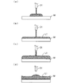
膜形成工程の詳細について説明する。図3は、図2の膜形成工程における基板W上のレジスト液の状態の変化を示す図である。
[3] Film forming step The details of the film forming step will be described. FIG. 3 is a diagram showing changes in the state of the resist liquid on the substrate W in the film forming step of FIG.
上記のように、第1の工程では、基板Wが比較的低い第1の速度A1で回転され、レジスト液が比較的低い第1のレートr1で吐出される。この場合、図3(a)に示すように、レジストノズル31から基板Wの被処理面の中心部上に吐出されたレジスト液が、基板Wの被処理面の径方向外方に徐々に拡げられる。
As described above, in the first step, the substrate W is rotated at a relatively low first speed A1, and the resist liquid is discharged at a relatively low first rate r1. In this case, as shown in FIG. 3A, the resist liquid discharged from the resist
第2の工程において、基板Wの回転速度が第1の速度A1から第2の速度A2に上昇される。基板Wの回転速度の上昇時に、基板W上のレジスト液に大きな遠心力が働き、基板Wの被処理面の全体を覆うようにレジスト液が基板Wの被処理面上の全体に拡がる。それにより、図3(b)に示すように、基板Wの被処理面上に、レジスト液の膜L1が形成される。 In the second step, the rotation speed of the substrate W is increased from the first speed A1 to the second speed A2. When the rotation speed of the substrate W increases, a large centrifugal force acts on the resist liquid on the substrate W, and the resist liquid spreads over the entire surface to be processed of the substrate W so as to cover the entire surface to be processed of the substrate W. As a result, as shown in FIG. 3B, a film L1 of the resist liquid is formed on the surface to be treated of the substrate W.
また、図2の例では、基板Wの回転速度が第1の変化率で第1の速度A1から中間速度A1’まで上昇された後に、第2の変化率で中間速度A1’から第2の速度A2まで上昇される。この場合、基板Wの回転速度が第1の速度A1から第2の速度A2まで一定の変化率(例えば第2の変化率)で上昇される場合に比べて、基板Wの被処理面上でレジスト液が安定的に拡がる。具体的には、平面視においてレジスト液が略円形を維持しながら径方向外方に安定的に拡がる。そのため、無駄なレジスト液の消費を抑制することができる。 Further, in the example of FIG. 2, after the rotation speed of the substrate W is increased from the first speed A1 to the intermediate speed A1'at the first rate of change, the intermediate speed A1'to the second at the second rate of change. It is increased to speed A2. In this case, the rotation speed of the substrate W is increased on the surface to be processed of the substrate W as compared with the case where the rotation speed of the substrate W is increased from the first velocity A1 to the second velocity A2 at a constant rate of change (for example, the second rate of change). The resist solution spreads stably. Specifically, the resist liquid stably spreads outward in the radial direction while maintaining a substantially circular shape in a plan view. Therefore, wasteful consumption of the resist liquid can be suppressed.
その後、基板Wが比較的高い第2の速度A2で回転されるとともに、レジスト液が比較的高い第2のレートr2で吐出される。それにより、図3(c)に示すように、膜L1の厚みが全体的に増加する。この場合、レジスト液の吐出レートが高いため、基板Wの被処理面上におけるレジスト液の流動性が確保される。それにより、基板Wの被処理面上の一部の領域上にレジスト液が蓄積されることが防止され、膜L1の厚みの均一性が高まる。 After that, the substrate W is rotated at a relatively high second speed A2, and the resist liquid is discharged at a relatively high second rate r2. As a result, as shown in FIG. 3C, the thickness of the film L1 is increased as a whole. In this case, since the discharge rate of the resist liquid is high, the fluidity of the resist liquid on the surface to be treated of the substrate W is ensured. As a result, the resist liquid is prevented from accumulating on a part of the region on the surface to be treated of the substrate W, and the uniformity of the thickness of the film L1 is enhanced.
第3の工程では、基板Wの回転速度が第3の速度A3に下降された後、レジスト液の吐出が停止される。この場合、基板W上のレジスト液に働く遠心力が小さくなり、基板Wの被処理面の中心部付近および外縁付近に僅かにレジスト液が蓄積される。これにより、図3(d)に示すように、膜L1の外縁部および中心部が僅かに上方に隆起した状態になる。膜L1の外縁部の厚みは、膜L1の中心部の厚みよりも小さいことが好ましい。 In the third step, after the rotation speed of the substrate W is lowered to the third speed A3, the discharge of the resist liquid is stopped. In this case, the centrifugal force acting on the resist liquid on the substrate W becomes small, and the resist liquid is slightly accumulated in the vicinity of the central portion and the outer edge of the surface to be processed of the substrate W. As a result, as shown in FIG. 3D, the outer edge portion and the central portion of the film L1 are slightly raised upward. The thickness of the outer edge portion of the film L1 is preferably smaller than the thickness of the central portion of the film L1.
レジスト液の吐出が停止される際には、レジストノズル31からレジスト液の滴が落下しやすい。仮に、基板Wが高速で回転される状態でレジスト液の滴が基板W上の膜L1に落下すると、膜L1の表面にレジスト液の落下跡が形成されたり、膜L1の状態が不安定になったりする。本例では、基板Wの回転速度が第2の速度A2から第3の速度A3に下降された後にレジスト液の吐出が停止される。それにより、レジスト液の滴が基板W上の膜L1に落下しても、落下跡の形成が防止されるとともに、膜L1が安定に保持される。
When the discharge of the resist liquid is stopped, the droplets of the resist liquid tend to fall from the resist
その後の第4の工程では、基板Wが比較的高い第4の速度A4で回転される。この場合、基板W上の膜L1の全体的な厚みが第4の速度A4に応じて微調整される。具体的には、第4の速度A4が高いほど、膜L1の全体的な厚みが小さくなり、第4の速度A4が低いほど、膜L1の全体的な厚みが大きくなる。第4の工程において、膜L1の断面形状は大きく変化せず、図3(d)の状態にほぼ維持される。第4の工程の終了時点で、膜L1が固化している。 In the subsequent fourth step, the substrate W is rotated at a relatively high fourth speed A4. In this case, the overall thickness of the film L1 on the substrate W is finely adjusted according to the fourth velocity A4. Specifically, the higher the fourth velocity A4, the smaller the overall thickness of the film L1, and the lower the fourth velocity A4, the larger the overall thickness of the film L1. In the fourth step, the cross-sectional shape of the film L1 does not change significantly and is substantially maintained in the state shown in FIG. 3 (d). At the end of the fourth step, the film L1 is solidified.
通常のフォトリソグラフィー工程では、基板Wの外縁から一定幅の範囲内にあるレジスト膜(レジスト液から形成された膜)の部分には、露光パターンが形成されない。したがって、図3(d)の例のような膜L1の外縁部の隆起は、露光パターンの形成にほとんど影響しない。 In a normal photolithography process, an exposure pattern is not formed on a portion of a resist film (a film formed from a resist solution) within a certain width from the outer edge of the substrate W. Therefore, the ridge of the outer edge of the film L1 as in the example of FIG. 3D has almost no effect on the formation of the exposure pattern.
次に、膜形成工程の比較例について説明する。図4は、膜形成工程の比較例における基板Wの回転速度の変化およびレジスト液の吐出レートの変化について説明するための図である。図4の膜形成工程が図2の膜形成工程と異なる点は、第1の工程において、レジスト液の吐出レートが第2のレートr2に調整され、第2の工程において、レジスト液の吐出レートが第1のレートr1に調整される点である。第3および第4の工程については、図2の例と同じである。 Next, a comparative example of the film forming step will be described. FIG. 4 is a diagram for explaining a change in the rotation speed of the substrate W and a change in the discharge rate of the resist liquid in the comparative example of the film forming step. The difference between the film forming step of FIG. 4 and the film forming step of FIG. 2 is that the discharge rate of the resist liquid is adjusted to the second rate r2 in the first step, and the discharge rate of the resist liquid is adjusted in the second step. Is adjusted to the first rate r1. The third and fourth steps are the same as in the example of FIG.
図5は、比較例における基板W上のレジスト液の状態の変化を示す図である。第1の工程においては、基板Wが比較的低い第1の速度A1で回転され、レジスト液が比較的高い第2のレートr2で吐出される。この場合、基板Wの被処理面の中心部に比較的多くのレジスト液が供給される一方で、基板W上のレジスト液に働く遠心力が比較的小さい。そのため、レジスト液の粘度が高い場合には、図5(a)に示すように、基板Wの被処理面の中心部上にレジスト液が蓄積されやすい。 FIG. 5 is a diagram showing changes in the state of the resist liquid on the substrate W in the comparative example. In the first step, the substrate W is rotated at a relatively low first speed A1 and the resist liquid is discharged at a relatively high second rate r2. In this case, while a relatively large amount of resist liquid is supplied to the central portion of the surface to be treated of the substrate W, the centrifugal force acting on the resist liquid on the substrate W is relatively small. Therefore, when the viscosity of the resist liquid is high, as shown in FIG. 5A, the resist liquid tends to accumulate on the central portion of the surface to be treated of the substrate W.
この場合、第2の工程で基板Wの回転速度が第2の速度A2に上昇されても、基板Wの被処理面の中心部上に蓄積されたレジスト液が径方向に十分に拡がらない。そのため、図5(b)に示すように、基板Wの被処理面上に形成される膜L1の中心部が上方に大きく隆起した状態になる。 In this case, even if the rotation speed of the substrate W is increased to the second speed A2 in the second step, the resist liquid accumulated on the central portion of the surface to be processed of the substrate W does not sufficiently spread in the radial direction. .. Therefore, as shown in FIG. 5B, the central portion of the film L1 formed on the surface to be processed of the substrate W is in a state of being greatly raised upward.
その後、基板Wが比較的高い第2の速度A2で回転され、レジスト液が比較的低い第1のレートr1で吐出される。この場合、レジスト液の吐出レートが低いため、基板Wの被処理面の中心部上に吐出されるレジスト液の流動性が低い。そのため、レジスト液が、基板Wの被処理面の外縁まで到達しにくく、基板Wの被処理面の周縁部上に蓄積される。そのため、図5(c)に示すように、膜L1の周縁部が上方に隆起する。その後の第3の工程および第4の工程においても、膜L1の中心部および周縁部が上方に大きく隆起した状態が維持される。 After that, the substrate W is rotated at a relatively high second speed A2, and the resist liquid is discharged at a relatively low first rate r1. In this case, since the discharge rate of the resist liquid is low, the fluidity of the resist liquid discharged onto the central portion of the surface to be processed of the substrate W is low. Therefore, it is difficult for the resist liquid to reach the outer edge of the surface to be processed of the substrate W, and the resist liquid is accumulated on the peripheral edge of the surface to be processed of the substrate W. Therefore, as shown in FIG. 5C, the peripheral edge of the film L1 rises upward. Also in the subsequent third step and the fourth step, the state in which the central portion and the peripheral portion of the film L1 are largely raised upward is maintained.
このように、比較例においては、レジスト液の粘度が高い場合に、膜L1の中心部および周縁部の厚みが上方に大きく隆起する。したがって、膜L1の厚みの均一性が低くなる。 As described above, in the comparative example, when the viscosity of the resist liquid is high, the thicknesses of the central portion and the peripheral portion of the film L1 are greatly raised upward. Therefore, the uniformity of the thickness of the film L1 becomes low.
それに対して、本実施の形態では、第1の工程でレジスト液の吐出レートが比較的低く調整されるため、レジスト液の粘度が高い場合でも、レジスト液の消費量を抑制しつつ基板Wの被処理面上でレジスト液を径方向外方に適切に拡げることができる。また、第2の工程でレジスト液の吐出レートが比較的高く調整されるため、レジスト液の粘度が高い場合でも、基板Wの被処理面上におけるレジスト液の流動性が確保される。それにより、基板Wの被処理面の周縁部上にレジスト液が蓄積されることを防止することができ、膜L1の厚みの均一性を高めることができる。 On the other hand, in the present embodiment, since the discharge rate of the resist liquid is adjusted to be relatively low in the first step, even when the viscosity of the resist liquid is high, the consumption of the resist liquid is suppressed and the substrate W The resist liquid can be appropriately spread radially outward on the surface to be treated. Further, since the discharge rate of the resist liquid is adjusted to be relatively high in the second step, the fluidity of the resist liquid on the surface to be treated of the substrate W is ensured even when the viscosity of the resist liquid is high. As a result, it is possible to prevent the resist liquid from accumulating on the peripheral edge of the surface to be treated of the substrate W, and it is possible to improve the uniformity of the thickness of the film L1.
[4]動作
図6は、基板処理装置100の機能的な構成を示すブロック図である。図6に示すように、基板処理装置100は、保持制御部51、吐出制御部53、第1の吐出レート調整部54、第2の吐出レート調整部55、第1の回転速度調整部56、第2の回転速度調整部57、第3の回転速度調整部58、第4の回転速度調整部59、第5の回転速度調整部60および時間制御部61を含む。これらの構成要素(51〜61)の機能は、制御部40のCPUがROMまたは記憶装置等の記憶媒体に記憶されたコンピュータプログラムを実行することにより実現される。
[4] Operation FIG. 6 is a block diagram showing a functional configuration of the substrate processing apparatus 100. As shown in FIG. 6, the substrate processing device 100 includes a holding
保持制御部51は、回転保持部10による基板Wの保持を制御する。吐出制御部53は、バルブV1の開閉を制御することにより、レジストノズル31(図1)からのレジスト液の吐出の開始および終了のタイミングを制御する。第1の吐出レート調整部54は、ポンプ45を制御することにより、レジストノズル31からのレジスト液の吐出レートを第1のレートr1に調整する。第2の吐出レート調整部55は、ポンプ45を制御することにより、レジストノズル31からのレジスト液の吐出レートを第2のレートr2に調整する。
The holding
第1の回転速度調整部56は、モータ11を制御することにより、基板Wの回転速度を第1の速度A1に調整する。第2の回転速度調整部57は、モータ11を制御することにより、基板Wの回転速度を第2の速度A2に調整する。第3の回転速度調整部58は、モータ11を制御することにより、基板Wの回転速度を第3の速度A3に調整する。第4の回転速度調整部59は、モータ11を制御することにより、基板Wの回転速度を第4の速度A4に調整する。第5の回転速度調整部60は、モータ11を制御することにより、基板Wの回転速度を第5の速度A5に調整する。
The first rotation
時間制御部61は、保持制御部51、吐出制御部53、第1の吐出レート調整部54、第2の吐出レート調整部55、第1の回転速度調整部56、第2の回転速度調整部57、第3の回転速度調整部58、第4の回転速度調整部59および第5の回転速度調整部60の動作の開始および終了のタイミングを制御する。
The
図7は、基板処理装置100の動作を示すフローチャートである。本例では、図2のプリウエット工程、洗浄工程および乾燥工程の時間が、プリウエット時間、洗浄時間および乾燥時間として予め定められる。また、図2の膜形成工程の第1の工程、第2の工程、第3の工程および第4の工程の時間が、低レート処理時間、高レート処理時間、低速回転時間および高速回転時間として予め定められる。 FIG. 7 is a flowchart showing the operation of the substrate processing device 100. In this example, the time of the pre-wetting step, the washing step, and the drying step of FIG. 2 is predetermined as the pre-wetting time, the washing time, and the drying time. Further, the time of the first step, the second step, the third step and the fourth step of the film forming step of FIG. 2 is defined as a low rate processing time, a high rate processing time, a low speed rotation time and a high speed rotation time. Predetermined.
初期状態では、図1のバルブV1〜V4は閉じられている。回転保持部10上に基板Wが載置されると、保持制御部51が回転保持部10を制御し、回転保持部10が基板Wを保持する(ステップS1)。次に、吐出制御部53がバルブV2を開くことにより、溶剤ノズル32からの溶剤の吐出を開始する(ステップS2)。ステップS2の処理から予め定められたプリウエット時間が経過すると、吐出制御部53は、バルブV2を閉じる。
In the initial state, the valves V1 to V4 of FIG. 1 are closed. When the substrate W is placed on the
次に、第1の回転速度調整部56が回転保持部10を制御して、基板Wの回転を開始する(ステップS3)。この場合、第1の回転速度調整部56は、基板Wの回転速度を第1の速度A1に調整する。また、吐出制御部53がバルブV1を開くことにより、レジストノズル31からのレジスト液の吐出を開始する(ステップS4)この場合、第1の吐出レート調整部54が、レジスト液の吐出レートを第1のレートr1に調整する。
Next, the first rotation
ステップS3,S4の処理から予め定められた低レート処理時間が経過すると、第2の回転速度調整部57が基板Wの回転速度を第2の速度A2に上昇させるとともに(ステップS5)、第2の吐出レート調整部55がレジスト液の吐出レートを第2のレートr2に上昇させる(ステップS6)。ステップS5,S6の処理から予め定められた高レート処理時間が経過すると、第3の回転速度調整部58が、基板Wの回転速度を第3の速度A3に下降させる(ステップS7)。次に、吐出制御部53が、バルブV2を閉じることによりレジストノズル31からのレジスト液の吐出を停止する(ステップS8)。
When a predetermined low rate processing time elapses from the processing in steps S3 and S4, the second rotation
ステップS7の処理から予め定められた低速回転時間が経過すると、第4の回転速度調整部59が、基板Wの回転速度を第4の速度A4に上昇させる(ステップS9)。ステップS9の処理から予め定められた高速回転時間が経過すると、吐出制御部53が、バルブV3,V4を開くことにより、エッジリンスノズル33からのエッジリンス液の吐出およびバックリンスノズル34からのバックリンス液の吐出を開始する(ステップS10)。ステップS10の処理から予め定められた洗浄時間が経過すると、吐出制御部53は、バルブV3,V4を閉じることによりエッジリンス液の吐出およびバックリンス液の吐出を停止する。
When a predetermined low-speed rotation time elapses from the process of step S7, the fourth rotation
次に、第5の回転速度調整部60が、基板Wの回転速度を速度A5に上昇させる(ステップS11)。これにより、基板Wからエッジリンス液およびバックリンス液が振り切られる。ステップS11の処理から予め定められた乾燥時間が経過すると、第5の回転速度調整部60が、基板Wの回転を停止する(ステップS12)。また、保持制御部51が、回転保持部10による基板Wの保持を解除する(ステップS13)。その後、回転保持部10上から基板Wが受け取られ、基板処理装置100の一連の動作が終了する。
Next, the fifth rotation
[5]効果
本実施の形態に係る基板処理装置100においては、膜形成工程の第1の工程において、回転する基板Wの一面(被処理面)の中心部に吐出されたレジスト液が基板Wの一面上で拡がるように、レジスト液の吐出レートが第1のレートr1に調整される。また、膜形成工程の第2の工程において、回転する基板Wの一面の全体に拡がったレジスト液の厚みが増加するように、レジスト液の吐出レートが第1のレートr1よりも高い第2のレートr2に調整される。
[5] Effect In the substrate processing apparatus 100 according to the present embodiment, in the first step of the film forming step, the resist liquid discharged to the center of one surface (processed surface) of the rotating substrate W is the substrate W. The discharge rate of the resist liquid is adjusted to the first rate r1 so as to spread on one surface. Further, in the second step of the film forming step, the discharge rate of the resist liquid is higher than that of the first rate r1 so that the thickness of the resist liquid spread over the entire surface of the rotating substrate W increases. Adjusted to rate r2.
この場合、第1の工程で比較的低い第1のレートr1でレジスト液が吐出されるため、レジスト液の消費量を抑制しつつ基板Wの一面上でレジスト液を拡げることができる。また、第2の工程で比較的高い第2のレートr2でレジスト液が吐出されるため、レジスト液の粘度が高い場合であっても、基板Wの一面上におけるレジスト液の流動性が確保される。それにより、基板Wの一面の一部の領域にレジスト液が蓄積されることが防止される。そのため、基板Wの一面上におけるレジスト液の厚みの均一性が高まる。したがって、レジスト液の消費量を抑制しつつ基板W上に形成されるレジスト液の膜の厚みの均一性を高めることができる。 In this case, since the resist liquid is discharged at a relatively low first rate r1 in the first step, the resist liquid can be spread on one surface of the substrate W while suppressing the consumption of the resist liquid. Further, since the resist liquid is discharged at a relatively high second rate r2 in the second step, the fluidity of the resist liquid on one surface of the substrate W is ensured even when the viscosity of the resist liquid is high. To. As a result, the resist liquid is prevented from accumulating in a part of one surface of the substrate W. Therefore, the uniformity of the thickness of the resist liquid on one surface of the substrate W is improved. Therefore, it is possible to increase the uniformity of the thickness of the resist liquid film formed on the substrate W while suppressing the consumption of the resist liquid.
また、本実施の形態では、第1の工程で基板Wの回転速度が第1の速度A1に調整され、第2の工程で基板Wの回転速度が第1の速度A1よりも高い第2の速度A2に調整される。この場合、第1の工程で基板Wが比較的低い速度で回転するため、基板Wの一面上でレジスト液を安定的に拡げることができる。それにより、レジスト液の消費量をさらに抑制することができる。また、第2の工程で基板Wが比較的高い速度で回転するため、レジスト液に働く遠心力が大きくなる。それにより、基板Wの一面の外縁までレジスト液を適切に拡げることができ、レジスト液の厚みの均一性をより高めることができる。 Further, in the present embodiment, the rotation speed of the substrate W is adjusted to the first speed A1 in the first step, and the rotation speed of the substrate W is higher than the first speed A1 in the second step. Adjusted to speed A2. In this case, since the substrate W rotates at a relatively low speed in the first step, the resist liquid can be stably spread on one surface of the substrate W. Thereby, the consumption amount of the resist liquid can be further suppressed. Further, since the substrate W rotates at a relatively high speed in the second step, the centrifugal force acting on the resist liquid becomes large. As a result, the resist liquid can be appropriately spread to the outer edge of one surface of the substrate W, and the uniformity of the thickness of the resist liquid can be further improved.
また、本実施の形態では、膜形成工程の第3の工程で、基板Wの回転速度が第3の速度A3に下降された後にレジスト液の吐出が停止される。これにより、レジスト液の吐出が停止される際にレジスト液の滴が基板W上のレジスト液の表面に落下しても、落下跡の形成が防止されるとともに、基板W上のレジスト液が安定に保持される。 Further, in the present embodiment, in the third step of the film forming step, the discharge of the resist liquid is stopped after the rotation speed of the substrate W is lowered to the third speed A3. As a result, even if a drop of the resist liquid drops on the surface of the resist liquid on the substrate W when the discharge of the resist liquid is stopped, the formation of a drop mark is prevented and the resist liquid on the substrate W is stable. Is held in.
また、本実施の形態では、膜形成工程の第4の工程で、基板Wの回転速度が第3の速度A3よりも高い第4の速度A4に調整される。これにより、第4の工程で基板Wの一面上のレジスト液の膜の厚みを適切に調整することができる。 Further, in the present embodiment, in the fourth step of the film forming step, the rotation speed of the substrate W is adjusted to the fourth speed A4, which is higher than the third speed A3. As a result, the thickness of the resist liquid film on one surface of the substrate W can be appropriately adjusted in the fourth step.
[6]他の実施の形態
(a)上記実施の形態においては、第1の工程でレジスト液の吐出レートが第1のレートr1に調整され、第2の工程でレジスト液の吐出レートが第2のレートr2に調整されるが、第1の工程でレジスト液の吐出レートが第1のレートr1を含む複数段階に調整されてもよく、第2の工程でレジスト液の吐出レートが第2のレートr2を含む複数段階に調整されてもよい。また、第1の工程および第2の工程の少なくとも一方において、レジスト液の吐出レートが連続的に変化するように調整されてもよい。
[6] Other Embodiments (a) In the above embodiment, the discharge rate of the resist liquid is adjusted to the first rate r1 in the first step, and the discharge rate of the resist liquid is the second in the second step. Although it is adjusted to the rate r2 of 2, the discharge rate of the resist liquid may be adjusted to a plurality of steps including the first rate r1 in the first step, and the discharge rate of the resist liquid is adjusted to the second rate in the second step. It may be adjusted in a plurality of steps including the rate r2 of. Further, in at least one of the first step and the second step, the discharge rate of the resist liquid may be adjusted so as to change continuously.
(b)上記実施の形態においては、第1の工程で基板Wの回転速度が第1の速度A1に調整され、第2の工程で基板Wの回転速度が第2の速度A2に調整されるが、第1の工程で基板Wの回転速度が第1の速度A1を含む複数段階に調整されてもよく、第2の工程で基板Wの回転速度が第2の速度A2を含む複数段階に調整されてもよい。また、第1の工程および第2の工程の少なくとも一方において、基板Wの回転速度が連続的に変化するように調整されてもよい。 (B) In the above embodiment, the rotation speed of the substrate W is adjusted to the first speed A1 in the first step, and the rotation speed of the substrate W is adjusted to the second speed A2 in the second step. However, in the first step, the rotation speed of the substrate W may be adjusted to a plurality of stages including the first speed A1, and in the second step, the rotation speed of the substrate W may be adjusted to a plurality of stages including the second speed A2. It may be adjusted. Further, in at least one of the first step and the second step, the rotation speed of the substrate W may be adjusted to change continuously.
(c)上記実施の形態においては、基板Wの回転速度が第1の速度A1に調整されるタイミングとレジスト液の吐出レートが第1のレートr1に調整されるタイミングとが同じであるが、これらのタイミングが互いにずれていてもよい。同様に、上記実施の形態においては、基板Wの回転速度が第2の速度A2に調整されるタイミングとレジスト液の吐出レートが第2のレートr2に調整されるタイミングとが同じであるが、これらのタイミングが互いにずれていてもよい。 (C) In the above embodiment, the timing at which the rotation speed of the substrate W is adjusted to the first speed A1 and the timing at which the discharge rate of the resist liquid is adjusted to the first rate r1 are the same. These timings may be offset from each other. Similarly, in the above embodiment, the timing at which the rotation speed of the substrate W is adjusted to the second speed A2 and the timing at which the discharge rate of the resist liquid is adjusted to the second rate r2 are the same. These timings may be offset from each other.
(d)上記実施の形態においては、基板Wの回転速度が第2の速度A2から第3の速度A3に下降された後にレジスト液の吐出が停止されるが、基板Wが第2の速度A2で回転されている状態でレジスト液の吐出が停止されてもよい。 (D) In the above embodiment, the discharge of the resist liquid is stopped after the rotation speed of the substrate W is lowered from the second speed A2 to the third speed A3, but the substrate W is the second speed A2. The discharge of the resist liquid may be stopped while being rotated by.
(e)上記実施の形態においては、基板Wの回転速度が第2の速度A2から第3の速度A3に下降された後に基板Wの回転速度が第3の速度A3から第4の速度A4に上昇されるが、基板Wの回転速度が第2の速度A2から第4の速度A4に直接的に変化されてもよい。 (E) In the above embodiment, the rotation speed of the substrate W is changed from the third speed A3 to the fourth speed A4 after the rotation speed of the substrate W is lowered from the second speed A2 to the third speed A3. Although it is increased, the rotation speed of the substrate W may be directly changed from the second speed A2 to the fourth speed A4.
(f)上記実施の形態では、塗布液としてレジスト液が用いられるが、レジスト液に代えて、下層膜用塗布液または層間絶縁膜用塗布液等の他の塗布液が用いられてもよい。
[7]参考形態
(1)第1の参考形態に係る基板処理装置は、基板を水平姿勢で保持して回転させる回転保持部と、回転保持部により回転する基板の一面の中心部に塗布液を吐出する塗布液吐出系と、第1の期間に、塗布液吐出系から基板の一面の中心部に吐出された塗布液が基板の一面上で拡がるように、塗布液吐出系からの塗布液の吐出レートを第1のレートに調整する第1の吐出レート調整部と、第1の期間の後の第2の期間に、基板の一面の全体に拡がった塗布液の厚みが増加するように、塗布液吐出系からの塗布液の吐出レートを第1のレートよりも高い第2のレートに調整する第2の吐出レート調整部とを備える。
この基板処理装置においては、第1の期間に、回転する基板の一面の中心部に吐出された塗布液が基板の一面上で拡がるように、塗布液の吐出レートが第1のレートに調整される。第1の期間の後の第2の期間に、回転する基板の一面の全体に拡がった塗布液の厚みが増加するように、塗布液の吐出レートが第1のレートよりも高い第2のレートに調整される。
この場合、第1の期間に比較的低い第1のレートで塗布液が吐出されるため、塗布液の消費量を抑制しつつ基板の一面上で塗布液を拡げることができる。また、第2の期間に比較的高い第2のレートで塗布液が吐出されるため、塗布液の粘度が高い場合であっても、基板の一面上における塗布液の流動性が確保される。それにより、基板の一面の一部の領域に塗布液が蓄積されることが防止される。そのため、基板の一面上における塗布液の厚みの均一性が高まる。したがって、塗布液の消費量を抑制しつつ基板上に形成される塗布液の膜の厚みの均一性を高めることができる。
(2)基板処理装置は、第1の期間に、回転保持部による基板の回転速度を第1の速度に調整する第1の回転速度調整部と、第2の期間に、回転保持部による基板の回転速度を第1の速度よりも高い第2の速度に調整する第2の回転速度調整部とをさらに備えてもよい。
この場合、第1の期間に基板が比較的低い第1の速度で回転するため、基板の一面上で塗布液を安定的に拡げることができる。それにより、塗布液の消費量がさらに抑制される。また、第2の期間に基板が比較的高い第2の速度で回転するため、塗布液に働く遠心力が大きくなる。それにより、基板の一面の外縁まで塗布液を適切に拡げることができ、塗布液の厚みの均一性をより高めることができる。
(3)第2の参考形態に係る基板処理装置は、基板を水平姿勢で保持して回転させる回転保持部と、回転保持部により回転する基板の一面の中心部に塗布液を吐出する塗布液吐出系と、第1の期間に、塗布液吐出系からの塗布液の吐出レートを第1のレートに調整する第1の吐出レート調整部と、第1の期間の後の第2の期間に、塗布液吐出系からの塗布液の吐出レートを第1のレートよりも高い第2のレートに調整する第2の吐出レート調整部と、第1の期間に、回転保持部による基板の回転速度を第1の速度に調整する第1の回転速度調整部と、第2の期間に、回転保持部による基板の回転速度を第1の速度よりも高い第2の速度に調整する第2の回転速度調整部とを備える。
この基板処理装置においては、第1の期間に、基板が第1の速度で回転しつつ基板の一面の中心部に第1のレートで塗布液が吐出される。第1の期間の後の第2の期間に、基板が第1の速度よりも高い第2の速度で回転しつつ基板の一面の中心部に第1のレートよりも高い第2のレートで塗布液が吐出される。
この場合、第1の期間に塗布液の消費量を抑制しつつ基板の一面上で塗布液を安定的に拡げることができる。第2の期間には、塗布液の粘度が高い場合であっても、基板の一面上における塗布液の流動性が確保される。それにより、基板の一面の一部の領域に塗布液が蓄積されることが防止される。そのため、基板の一面上における塗布液の厚みの均一性が高まる。したがって、塗布液の消費量を抑制しつつ基板上に形成される塗布液の膜の厚みの均一性を高めることができる。
(4)基板処理装置は、第2の期間の後の第3の期間に、回転保持部による基板の回転速度を第1の速度よりも高くかつ第2の速度よりも低い第3の速度に調整する第3の回転速度調整部と、第3の期間に塗布液の吐出を停止させる吐出停止部とをさらに備えてもよい。
この場合、基板の回転速度が第2の速度から第3の速度に下降された後に塗布液の吐出が停止されるので、塗布液の吐出が停止される際に塗布液の滴が基板の一面上の塗布液の表面に落下しても、基板の一面上で塗布液が安定的に保持される。それにより、塗布液の膜の厚みの均一性をより高めることができる。
(5)基板処理装置は、第3の期間の後の第4の期間に、回転保持部による基板の回転速度を第3の速度よりも高くかつ第2の速度よりも低い第4の速度に調整する第4の回転速度調整部をさらに備えてもよい。
この場合、第4の期間に基板の一面上の塗布液の膜の厚みを適切に調整することができる。
(6)第3の参考形態に係る基板処理方法は、第1の期間に、基板の一面上で塗布液が拡がるように、回転保持部により基板を回転させつつ塗布液吐出系により基板の一面の中心部に第1のレートで塗布液を吐出するステップと、第1の期間の後の第2の期間に、基板の一面の全体に広がった塗布液の厚みが増加されるように、回転保持部により基板を回転させつつ塗布液吐出系により基板の一面の中心部に第1のレートよりも高い第2のレートで塗布液を吐出するステップとを含む。
この基板処理方法によれば、第1の期間に、塗布液が基板の一面上で拡がるように、回転する基板の一面の中心部に塗布液が第1のレートで吐出される。第1の期間の後の第2の期間に、基板の一面の全体に拡がった塗布液の厚みが増加するように、回転する基板の一面の中心部に塗布液が吐出レートが第1のレートよりも高い第2のレートで吐出される。
この場合、第1の期間に比較的低い第1のレートで塗布液が吐出されるため、塗布液の消費量を抑制しつつ基板の一面上で塗布液を拡げることができる。また、第2の期間に比較的高い第2のレートで塗布液が吐出されるため、塗布液の粘度が高い場合であっても、基板の一面上における塗布液の流動性が確保される。それにより、基板の一面の一部の領域に塗布液が蓄積されることが防止される。そのため、基板の一面上における塗布液の厚みの均一性が高まる。したがって、塗布液の消費量を抑制しつつ基板上に形成される塗布液の膜の厚みの均一性を高めることができる。
(7)第4の参考形態に係る基板処理方法は、第1の期間に、回転保持部により基板を第1の速度で回転させつつ塗布液吐出系により基板の一面の中心部に第1のレートで塗布液を吐出するステップと、第1の期間の後の第2の期間に、回転保持部により基板を第1の速度よりも高い第2の速度で回転させつつ塗布液吐出系により基板の一面の中心部に第1のレートよりも高い第2のレートで塗布液を吐出するステップとを含んでもよい。
この基板処理装置においては、第1の期間に、基板が第1の速度で回転しつつ基板の一面の中心部に第1のレートで塗布液が吐出される。第1の期間の後の第2の期間に、基板が第1の速度よりも高い第2の速度で回転しつつ基板の一面の中心部に第1のレートよりも高い第2のレートで塗布液が吐出される。
この場合、第1の期間に塗布液の消費量を抑制しつつ基板の一面上で塗布液を安定的に拡げることができる。第2の期間には、塗布液の粘度が高い場合であっても、基板の一面上における塗布液の流動性が確保される。それにより、基板の一面の一部の領域に塗布液が蓄積されることが防止される。そのため、基板の一面上における塗布液の厚みの均一性が高まる。したがって、塗布液の消費量を抑制しつつ基板上に形成される塗布液の膜の厚みの均一性を高めることができる。
(F) In the above embodiment, the resist liquid is used as the coating liquid, but instead of the resist liquid, another coating liquid such as a coating liquid for an underlayer film or a coating liquid for an interlayer insulating film may be used.
[7] Reference form
(1) The substrate processing apparatus according to the first reference embodiment has a rotation holding portion that holds and rotates the substrate in a horizontal posture, and a coating liquid that discharges the coating liquid to the center of one surface of the substrate that is rotated by the rotation holding portion. The discharge rate of the coating liquid from the coating liquid discharge system is set so that the coating liquid discharged from the coating liquid discharge system to the center of one surface of the substrate spreads on one surface of the substrate during the discharge system and the first period. The coating liquid discharge system so that the thickness of the coating liquid spread over the entire surface of the substrate increases in the first discharge rate adjusting unit that adjusts to the rate of 1 and in the second period after the first period. It is provided with a second discharge rate adjusting unit that adjusts the discharge rate of the coating liquid from the above to a second rate higher than the first rate.
In this substrate processing apparatus, the discharge rate of the coating liquid is adjusted to the first rate so that the coating liquid discharged to the center of one surface of the rotating substrate spreads on one surface of the substrate during the first period. To. In the second period after the first period, the discharge rate of the coating liquid is higher than the first rate so that the thickness of the coating liquid spread over the entire surface of the rotating substrate increases. Is adjusted to.
In this case, since the coating liquid is discharged at a relatively low first rate during the first period, the coating liquid can be spread on one surface of the substrate while suppressing the consumption of the coating liquid. Further, since the coating liquid is discharged at a relatively high second rate in the second period, the fluidity of the coating liquid on one surface of the substrate is ensured even when the viscosity of the coating liquid is high. As a result, the coating liquid is prevented from accumulating in a part of one surface of the substrate. Therefore, the uniformity of the thickness of the coating liquid on one surface of the substrate is improved. Therefore, it is possible to increase the uniformity of the thickness of the coating liquid film formed on the substrate while suppressing the consumption of the coating liquid.
(2) The substrate processing apparatus includes a first rotation speed adjusting unit that adjusts the rotation speed of the substrate by the rotation holding unit to the first speed in the first period, and a substrate by the rotation holding unit in the second period. A second rotation speed adjusting unit may be further provided to adjust the rotation speed of the above to a second speed higher than the first speed.
In this case, since the substrate rotates at a relatively low first speed during the first period, the coating liquid can be stably spread on one surface of the substrate. As a result, the consumption of the coating liquid is further suppressed. Further, since the substrate rotates at a relatively high second speed during the second period, the centrifugal force acting on the coating liquid becomes large. As a result, the coating liquid can be appropriately spread to the outer edge of one surface of the substrate, and the uniformity of the thickness of the coating liquid can be further improved.
(3) The substrate processing apparatus according to the second reference embodiment has a rotation holding portion that holds and rotates the substrate in a horizontal posture, and a coating liquid that discharges the coating liquid to the center of one surface of the substrate that is rotated by the rotation holding portion. In the discharge system, in the first period, in the first discharge rate adjusting unit that adjusts the discharge rate of the coating liquid from the coating liquid discharge system to the first rate, and in the second period after the first period. , The second discharge rate adjusting unit that adjusts the discharge rate of the coating liquid from the coating liquid discharge system to a second rate higher than the first rate, and the rotation speed of the substrate by the rotation holding unit during the first period. A first rotation speed adjusting unit that adjusts the speed to the first speed, and a second rotation that adjusts the rotation speed of the substrate by the rotation holding unit to a second speed higher than the first speed during the second period. It is equipped with a speed adjustment unit.
In this substrate processing apparatus, the coating liquid is discharged at the first rate to the central portion of one surface of the substrate while the substrate rotates at the first speed during the first period. In the second period after the first period, the substrate is applied to the center of one surface of the substrate at a second rate higher than the first rate while rotating at a second speed higher than the first speed. The liquid is discharged.
In this case, the coating liquid can be stably spread on one surface of the substrate while suppressing the consumption of the coating liquid in the first period. In the second period, the fluidity of the coating liquid on one surface of the substrate is ensured even when the viscosity of the coating liquid is high. As a result, the coating liquid is prevented from accumulating in a part of one surface of the substrate. Therefore, the uniformity of the thickness of the coating liquid on one surface of the substrate is improved. Therefore, it is possible to increase the uniformity of the thickness of the coating liquid film formed on the substrate while suppressing the consumption of the coating liquid.
(4) In the third period after the second period, the substrate processing apparatus sets the rotation speed of the substrate by the rotation holding unit to a third speed higher than the first speed and lower than the second speed. A third rotation speed adjusting unit for adjusting and a discharge stopping unit for stopping the discharge of the coating liquid during the third period may be further provided.
In this case, since the discharge of the coating liquid is stopped after the rotation speed of the substrate is lowered from the second speed to the third speed, the droplets of the coating liquid are dropped on one surface of the substrate when the discharge of the coating liquid is stopped. Even if it falls on the surface of the above coating liquid, the coating liquid is stably held on one surface of the substrate. Thereby, the uniformity of the film thickness of the coating liquid can be further improved.
(5) In the fourth period after the third period, the substrate processing apparatus sets the rotation speed of the substrate by the rotation holding unit to a fourth speed higher than the third speed and lower than the second speed. A fourth rotation speed adjusting unit for adjusting may be further provided.
In this case, the thickness of the coating liquid film on one surface of the substrate can be appropriately adjusted during the fourth period.
(6) In the substrate processing method according to the third reference embodiment, one surface of the substrate is rotated by the rotation holding portion and the coating liquid is discharged so that the coating liquid spreads on one surface of the substrate in the first period. Rotate so that the thickness of the coating liquid spread over the entire surface of the substrate is increased in the step of discharging the coating liquid to the center of the substrate at the first rate and in the second period after the first period. The step includes a step of discharging the coating liquid at a second rate higher than the first rate to the central portion of one surface of the substrate by the coating liquid discharging system while rotating the substrate by the holding portion.
According to this substrate processing method, during the first period, the coating liquid is discharged at the first rate to the central portion of one surface of the rotating substrate so that the coating liquid spreads on one surface of the substrate. In the second period after the first period, the coating liquid is discharged to the center of one surface of the rotating substrate so that the thickness of the coating liquid spread over the entire surface of the substrate increases. It is discharged at a higher second rate.
In this case, since the coating liquid is discharged at a relatively low first rate during the first period, the coating liquid can be spread on one surface of the substrate while suppressing the consumption of the coating liquid. Further, since the coating liquid is discharged at a relatively high second rate in the second period, the fluidity of the coating liquid on one surface of the substrate is ensured even when the viscosity of the coating liquid is high. As a result, the coating liquid is prevented from accumulating in a part of one surface of the substrate. Therefore, the uniformity of the thickness of the coating liquid on one surface of the substrate is improved. Therefore, it is possible to increase the uniformity of the thickness of the coating liquid film formed on the substrate while suppressing the consumption of the coating liquid.
(7) In the substrate processing method according to the fourth reference embodiment, in the first period, the substrate is rotated at the first speed by the rotation holding portion, and the coating liquid discharge system is applied to the central portion of one surface of the substrate. In the step of discharging the coating liquid at a rate and in the second period after the first period, the substrate is rotated by the rotation holding portion at a second speed higher than the first speed, and the substrate is discharged by the coating liquid discharge system. A step of discharging the coating liquid at a second rate higher than the first rate may be included in the central portion of one surface.
In this substrate processing apparatus, the coating liquid is discharged at the first rate to the central portion of one surface of the substrate while the substrate rotates at the first speed during the first period. In the second period after the first period, the substrate is applied to the center of one surface of the substrate at a second rate higher than the first rate while rotating at a second speed higher than the first speed. The liquid is discharged.
In this case, the coating liquid can be stably spread on one surface of the substrate while suppressing the consumption of the coating liquid in the first period. In the second period, the fluidity of the coating liquid on one surface of the substrate is ensured even when the viscosity of the coating liquid is high. As a result, the coating liquid is prevented from accumulating in a part of one surface of the substrate. Therefore, the uniformity of the thickness of the coating liquid on one surface of the substrate is improved. Therefore, it is possible to increase the uniformity of the thickness of the coating liquid film formed on the substrate while suppressing the consumption of the coating liquid.
10…回転保持部,11…モータ,12…回転軸,20…カップ,30…ノズルユニット,31…レジストノズル,31A…レジスト液吐出系,32…溶剤ノズル,33…エッジリンスノズル,34…バックリンスノズル,40…制御部,45…ポンプ,100…基板処理装置,T1…供給管,T2…レジスト液溶剤供給管,T3…エッジリンス液供給管,T4…バックリンス液供給管,P1…レジスト液供給源,P2…溶剤供給源,P3…エッジリンス液供給源,P4…バックリンス液供給源 10 ... Rotation holding part, 11 ... Motor, 12 ... Rotating shaft, 20 ... Cup, 30 ... Nozzle unit, 31 ... Resist nozzle, 31A ... Resist liquid discharge system, 32 ... Solvent nozzle, 33 ... Edge rinse nozzle, 34 ... Back Rinse nozzle, 40 ... Control unit, 45 ... Pump, 100 ... Substrate processing device, T1 ... Supply pipe, T2 ... Resist liquid solvent supply pipe, T3 ... Edge rinse liquid supply pipe, T4 ... Back rinse liquid supply pipe, P1 ... Resist Liquid supply source, P2 ... Nozzle supply source, P3 ... Edge rinse liquid supply source, P4 ... Back rinse liquid supply source
Claims (6)
前記回転保持部により回転する基板の一面の中心部に塗布液を吐出する塗布液吐出系と、
第1の期間に、前記塗布液吐出系から基板の前記一面の中心部に吐出された塗布液が基板の前記一面上で拡がるように、前記塗布液吐出系からの塗布液の吐出レートを第1のレートに調整する第1の吐出レート調整部と、
前記第1の期間の後の第2の期間に、基板の前記一面の全体に拡がった塗布液の厚みが増加するように、前記塗布液吐出系からの塗布液の吐出レートを前記第1のレートよりも高い第2のレートに調整する第2の吐出レート調整部と、
前記第1の期間に、前記回転保持部による基板の回転速度を第1の速度に調整する第1の回転速度調整部と、
前記第2の期間に、前記回転保持部による基板の回転速度を前記第1の速度よりも高い第2の速度に調整する第2の回転速度調整部とを備える、基板処理装置。 A rotation holding part that holds and rotates the board in a horizontal position,
A coating liquid discharge system that discharges the coating liquid to the center of one surface of the substrate that is rotated by the rotation holding portion,
In the first period, the discharge rate of the coating liquid from the coating liquid discharge system is set so that the coating liquid discharged from the coating liquid discharge system to the center of the one surface of the substrate spreads on the one surface of the substrate. The first discharge rate adjusting unit that adjusts to the rate of 1 and
In the second period after the first period, the discharge rate of the coating liquid from the coating liquid discharge system is set so that the thickness of the coating liquid spread over the entire surface of the substrate increases. A second discharge rate adjusting unit that adjusts to a second rate higher than the rate ,
During the first period, the first rotation speed adjusting unit that adjusts the rotation speed of the substrate by the rotation holding unit to the first speed,
A substrate processing apparatus including a second rotation speed adjusting unit that adjusts the rotation speed of the substrate by the rotation holding unit to a second speed higher than the first speed during the second period.
前記回転保持部により回転する基板の一面の中心部に塗布液を吐出する塗布液吐出系と、
第1の期間に、前記塗布液吐出系からの塗布液の吐出レートを第1のレートに調整する第1の吐出レート調整部と、
前記第1の期間の後の第2の期間に、前記塗布液吐出系からの塗布液の吐出レートを前記第1のレートよりも高い第2のレートに調整する第2の吐出レート調整部と、
前記第1の期間に、前記回転保持部による基板の回転速度を第1の速度に調整する第1の回転速度調整部と、
前記第2の期間に、前記回転保持部による基板の回転速度を前記第1の速度よりも高い第2の速度に調整する第2の回転速度調整部とを備える、基板処理装置。 A rotation holding part that holds and rotates the board in a horizontal position,
A coating liquid discharge system that discharges the coating liquid to the center of one surface of the substrate that is rotated by the rotation holding portion,
In the first period, the first discharge rate adjusting unit that adjusts the discharge rate of the coating liquid from the coating liquid discharge system to the first rate, and
With a second discharge rate adjusting unit that adjusts the discharge rate of the coating liquid from the coating liquid discharge system to a second rate higher than the first rate in the second period after the first period. ,
During the first period, the first rotation speed adjusting unit that adjusts the rotation speed of the substrate by the rotation holding unit to the first speed,
A substrate processing apparatus including a second rotation speed adjusting unit that adjusts the rotation speed of the substrate by the rotation holding unit to a second speed higher than the first speed during the second period.
前記第3の期間に塗布液の吐出を停止させる吐出停止部とをさらに備える、請求項1または2記載の基板処理装置。 In the third period after the second period, the rotation speed of the substrate by the rotation holding portion is adjusted to a third speed higher than the first speed and lower than the second speed. Rotation speed adjustment part and
The substrate processing apparatus according to claim 1 or 2 , further comprising a discharge stop portion for stopping the discharge of the coating liquid during the third period.
前記第1の期間の後の第2の期間に、基板の前記一面の全体に広がった塗布液の厚みが増加されるように、前記回転保持部により基板を前記第1の速度よりも高い第2の速度で回転させつつ前記塗布液吐出系により基板の前記一面の中心部に前記第1のレートよりも高い第2のレートで塗布液を吐出するステップとを含む、基板処理方法。 In the first period, the coating liquid discharge system rotates the substrate at the first speed by the rotation holding portion so that the coating liquid spreads on one surface of the substrate at the first rate at the center of the one surface of the substrate. Steps to discharge the coating liquid and
In the second period after the first period, the rotation holding portion causes the substrate to be higher than the first speed so that the thickness of the coating liquid spread over the entire surface of the substrate is increased. A substrate processing method comprising a step of discharging a coating liquid at a second rate higher than the first rate to a central portion of the one surface of the substrate by the coating liquid discharging system while rotating at a speed of 2.
前記第1の期間の後の第2の期間に、前記回転保持部により基板を前記第1の速度よりも高い第2の速度で回転させつつ前記塗布液吐出系により基板の前記一面の中心部に前記第1のレートよりも高い第2のレートで塗布液を吐出するステップとを含む、基板処理方法。 In the first period, the step of discharging the coating liquid at the first rate to the central portion of one surface of the substrate by the coating liquid discharging system while rotating the substrate at the first speed by the rotation holding portion.
In the second period after the first period, the center portion of the one surface of the substrate is rotated by the coating liquid discharge system while the substrate is rotated at a second speed higher than the first speed by the rotation holding portion. A substrate processing method comprising the step of discharging a coating liquid at a second rate higher than the first rate.
Priority Applications (5)
| Application Number | Priority Date | Filing Date | Title |
|---|---|---|---|
| JP2017165379A JP6873011B2 (en) | 2017-08-30 | 2017-08-30 | Substrate processing equipment and substrate processing method |
| CN201880025759.1A CN110537245B (en) | 2017-08-30 | 2018-07-27 | Substrate processing apparatus and substrate processing method |
| PCT/JP2018/028337 WO2019044314A1 (en) | 2017-08-30 | 2018-07-27 | Substrate processing apparatus and substrate processing method |
| KR1020197030074A KR102296706B1 (en) | 2017-08-30 | 2018-07-27 | Substrate processing apparatus and substrate processing method |
| TW107126312A TWI669751B (en) | 2017-08-30 | 2018-07-30 | Substrate processing apparatus and substrate processing method |
Applications Claiming Priority (1)
| Application Number | Priority Date | Filing Date | Title |
|---|---|---|---|
| JP2017165379A JP6873011B2 (en) | 2017-08-30 | 2017-08-30 | Substrate processing equipment and substrate processing method |
Publications (3)
| Publication Number | Publication Date |
|---|---|
| JP2019046850A JP2019046850A (en) | 2019-03-22 |
| JP2019046850A5 JP2019046850A5 (en) | 2020-09-10 |
| JP6873011B2 true JP6873011B2 (en) | 2021-05-19 |
Family
ID=65526446
Family Applications (1)
| Application Number | Title | Priority Date | Filing Date |
|---|---|---|---|
| JP2017165379A Active JP6873011B2 (en) | 2017-08-30 | 2017-08-30 | Substrate processing equipment and substrate processing method |
Country Status (5)
| Country | Link |
|---|---|
| JP (1) | JP6873011B2 (en) |
| KR (1) | KR102296706B1 (en) |
| CN (1) | CN110537245B (en) |
| TW (1) | TWI669751B (en) |
| WO (1) | WO2019044314A1 (en) |
Families Citing this family (5)
| Publication number | Priority date | Publication date | Assignee | Title |
|---|---|---|---|---|
| TW202116420A (en) * | 2019-07-04 | 2021-05-01 | 日商東京威力科創股份有限公司 | Coating method and coating device |
| JP2022178694A (en) * | 2021-05-20 | 2022-12-02 | 株式会社Screenホールディングス | Coating method and coating system |
| JP2022178623A (en) * | 2021-05-20 | 2022-12-02 | 株式会社Screenホールディングス | Coating method and coating system |
| KR102600411B1 (en) * | 2021-08-12 | 2023-11-09 | 세메스 주식회사 | Apparatus for treating substrate and method for treating substrate |
| KR102488391B1 (en) | 2022-01-11 | 2023-01-13 | (주)예성글로벌 | Panic device with door closer |
Family Cites Families (12)
| Publication number | Priority date | Publication date | Assignee | Title |
|---|---|---|---|---|
| KR100284556B1 (en) * | 1993-03-25 | 2001-04-02 | 다카시마 히로시 | Coating film forming method and apparatus therefor |
| JP3471168B2 (en) * | 1996-04-25 | 2003-11-25 | 大日本スクリーン製造株式会社 | Substrate processing method and apparatus |
| JP3527459B2 (en) | 2000-04-12 | 2004-05-17 | 東京エレクトロン株式会社 | Coating film forming method and coating processing apparatus |
| JP5065071B2 (en) * | 2007-03-15 | 2012-10-31 | 東京エレクトロン株式会社 | Coating processing method, coating processing apparatus, and computer-readable storage medium |
| JP4745358B2 (en) * | 2008-03-04 | 2011-08-10 | 株式会社東芝 | Spin coating method and spin coating apparatus |
| JP5091722B2 (en) * | 2008-03-04 | 2012-12-05 | 東京エレクトロン株式会社 | Coating processing method, program, computer storage medium, and coating processing apparatus |
| KR101447759B1 (en) * | 2008-12-16 | 2014-10-06 | 도쿄엘렉트론가부시키가이샤 | Application processing method and application processing apparatus |
| JP5485672B2 (en) * | 2009-12-07 | 2014-05-07 | 株式会社Sokudo | Substrate processing apparatus and substrate processing method |
| JP5337180B2 (en) * | 2010-04-08 | 2013-11-06 | 東京エレクトロン株式会社 | Coating processing method, program, computer storage medium, and coating processing apparatus |
| JP2014050803A (en) * | 2012-09-07 | 2014-03-20 | Toshiba Corp | Rotary application equipment and rotary application method |
| TWI666684B (en) * | 2015-11-16 | 2019-07-21 | 日商東京威力科創股份有限公司 | Coating film forming method, coating film forming device and memory medium |
| JP6374373B2 (en) * | 2015-12-04 | 2018-08-15 | 東芝メモリ株式会社 | Spin coater |
-
2017
- 2017-08-30 JP JP2017165379A patent/JP6873011B2/en active Active
-
2018
- 2018-07-27 WO PCT/JP2018/028337 patent/WO2019044314A1/en active Application Filing
- 2018-07-27 CN CN201880025759.1A patent/CN110537245B/en active Active
- 2018-07-27 KR KR1020197030074A patent/KR102296706B1/en active IP Right Grant
- 2018-07-30 TW TW107126312A patent/TWI669751B/en active
Also Published As
| Publication number | Publication date |
|---|---|
| KR102296706B1 (en) | 2021-09-01 |
| CN110537245A (en) | 2019-12-03 |
| TWI669751B (en) | 2019-08-21 |
| WO2019044314A1 (en) | 2019-03-07 |
| KR20190125469A (en) | 2019-11-06 |
| TW201913728A (en) | 2019-04-01 |
| JP2019046850A (en) | 2019-03-22 |
| CN110537245B (en) | 2023-05-02 |
Similar Documents
| Publication | Publication Date | Title |
|---|---|---|
| JP6873011B2 (en) | Substrate processing equipment and substrate processing method | |
| KR100998837B1 (en) | Coating apparatus and coating method | |
| US8580340B2 (en) | Substrate processing apparatus and substrate processing method | |
| KR102016824B1 (en) | Application method | |
| US10144033B2 (en) | Substrate processing apparatus and substrate processing method | |
| JP2007318087A (en) | Developing device, development processing method, development processing program, and computer-readable recording medium with program recorded thereon | |
| JP6755962B2 (en) | Liquid treatment method and liquid treatment equipment | |
| JP6654534B2 (en) | Substrate processing apparatus and substrate processing method | |
| JP2015015453A (en) | Substrate processing apparatus, substrate processing method and computer-readable storage medium recording substrate processing program therein | |
| JP2009004597A (en) | Substrate development method and developing apparatus | |
| WO2017169019A1 (en) | Substrate processing method and substrate processing apparatus | |
| JP7073658B2 (en) | Board processing method, board processing device, and storage medium | |
| JP2020170851A (en) | Coating film forming device and coating film forming method | |
| JP6983571B2 (en) | Board processing method and board processing equipment | |
| JP6481644B2 (en) | Substrate processing method, substrate processing apparatus, and storage medium | |
| JPH11168041A (en) | Method for forming resist film | |
| US20120162618A1 (en) | Substrate processing device and method | |
| CN108153117A (en) | Substrate processing device, processing method for substrate and storage medium | |
| JP7136543B2 (en) | Substrate processing method and substrate processing apparatus | |
| KR20200124166A (en) | Substrate treatment method and substrate treatment apparatus | |
| JP3451158B2 (en) | Method and apparatus for rotary development processing of substrate | |
| JP2002343704A (en) | Method and system for forming coating film | |
| KR100359249B1 (en) | Method for eliminating bubble in an bottom anti reflective coating | |
| JP6690717B2 (en) | Coating method, coating device and storage medium | |
| JP2580082B2 (en) | Substrate rotation processing equipment |
Legal Events
| Date | Code | Title | Description |
|---|---|---|---|
| A621 | Written request for application examination |
Free format text: JAPANESE INTERMEDIATE CODE: A621 Effective date: 20200622 |
|
| A521 | Request for written amendment filed |
Free format text: JAPANESE INTERMEDIATE CODE: A523 Effective date: 20200730 |
|
| A131 | Notification of reasons for refusal |
Free format text: JAPANESE INTERMEDIATE CODE: A131 Effective date: 20201222 |
|
| A521 | Request for written amendment filed |
Free format text: JAPANESE INTERMEDIATE CODE: A523 Effective date: 20210212 |
|
| TRDD | Decision of grant or rejection written | ||
| A01 | Written decision to grant a patent or to grant a registration (utility model) |
Free format text: JAPANESE INTERMEDIATE CODE: A01 Effective date: 20210330 |
|
| A61 | First payment of annual fees (during grant procedure) |
Free format text: JAPANESE INTERMEDIATE CODE: A61 Effective date: 20210420 |
|
| R150 | Certificate of patent or registration of utility model |
Ref document number: 6873011 Country of ref document: JP Free format text: JAPANESE INTERMEDIATE CODE: R150 |
|
| R250 | Receipt of annual fees |
Free format text: JAPANESE INTERMEDIATE CODE: R250 |