JP6861450B1 - A device that drills holes in the surface of the object to be treated. - Google Patents
A device that drills holes in the surface of the object to be treated. Download PDFInfo
- Publication number
- JP6861450B1 JP6861450B1 JP2020195263A JP2020195263A JP6861450B1 JP 6861450 B1 JP6861450 B1 JP 6861450B1 JP 2020195263 A JP2020195263 A JP 2020195263A JP 2020195263 A JP2020195263 A JP 2020195263A JP 6861450 B1 JP6861450 B1 JP 6861450B1
- Authority
- JP
- Japan
- Prior art keywords
- head
- perforation
- needle
- drilling
- processed
- Prior art date
- Legal status (The legal status is an assumption and is not a legal conclusion. Google has not performed a legal analysis and makes no representation as to the accuracy of the status listed.)
- Active
Links
- 238000005553 drilling Methods 0.000 claims abstract description 277
- 230000000149 penetrating effect Effects 0.000 claims abstract description 82
- 230000003028 elevating effect Effects 0.000 claims description 25
- 239000000463 material Substances 0.000 claims description 19
- NJPPVKZQTLUDBO-UHFFFAOYSA-N novaluron Chemical compound C1=C(Cl)C(OC(F)(F)C(OC(F)(F)F)F)=CC=C1NC(=O)NC(=O)C1=C(F)C=CC=C1F NJPPVKZQTLUDBO-UHFFFAOYSA-N 0.000 claims description 10
- 238000000034 method Methods 0.000 claims description 8
- 235000013305 food Nutrition 0.000 claims description 6
- 238000010586 diagram Methods 0.000 abstract description 4
- 241000251468 Actinopterygii Species 0.000 description 27
- 238000004080 punching Methods 0.000 description 19
- 239000011347 resin Substances 0.000 description 18
- 229920005989 resin Polymers 0.000 description 18
- 239000012779 reinforcing material Substances 0.000 description 16
- 239000002184 metal Substances 0.000 description 10
- 229910052751 metal Inorganic materials 0.000 description 10
- 230000003014 reinforcing effect Effects 0.000 description 9
- 230000035515 penetration Effects 0.000 description 8
- 238000003466 welding Methods 0.000 description 8
- 238000003780 insertion Methods 0.000 description 7
- 230000037431 insertion Effects 0.000 description 7
- 238000003825 pressing Methods 0.000 description 7
- 125000006850 spacer group Chemical group 0.000 description 7
- 239000007769 metal material Substances 0.000 description 6
- 238000000926 separation method Methods 0.000 description 6
- 238000013459 approach Methods 0.000 description 5
- 210000002615 epidermis Anatomy 0.000 description 5
- 229910001220 stainless steel Inorganic materials 0.000 description 4
- 239000010935 stainless steel Substances 0.000 description 4
- 239000002344 surface layer Substances 0.000 description 4
- 239000000853 adhesive Substances 0.000 description 3
- 230000001070 adhesive effect Effects 0.000 description 3
- 241000252073 Anguilliformes Species 0.000 description 2
- KAKZBPTYRLMSJV-UHFFFAOYSA-N Butadiene Chemical compound C=CC=C KAKZBPTYRLMSJV-UHFFFAOYSA-N 0.000 description 2
- RYGMFSIKBFXOCR-UHFFFAOYSA-N Copper Chemical compound [Cu] RYGMFSIKBFXOCR-UHFFFAOYSA-N 0.000 description 2
- PPBRXRYQALVLMV-UHFFFAOYSA-N Styrene Chemical compound C=CC1=CC=CC=C1 PPBRXRYQALVLMV-UHFFFAOYSA-N 0.000 description 2
- BZHJMEDXRYGGRV-UHFFFAOYSA-N Vinyl chloride Chemical compound ClC=C BZHJMEDXRYGGRV-UHFFFAOYSA-N 0.000 description 2
- NIXOWILDQLNWCW-UHFFFAOYSA-N acrylic acid group Chemical group C(C=C)(=O)O NIXOWILDQLNWCW-UHFFFAOYSA-N 0.000 description 2
- 229910052802 copper Inorganic materials 0.000 description 2
- 239000010949 copper Substances 0.000 description 2
- 239000013585 weight reducing agent Substances 0.000 description 2
- NLHHRLWOUZZQLW-UHFFFAOYSA-N Acrylonitrile Chemical compound C=CC#N NLHHRLWOUZZQLW-UHFFFAOYSA-N 0.000 description 1
- 241000252095 Congridae Species 0.000 description 1
- 241000287828 Gallus gallus Species 0.000 description 1
- 241000282887 Suidae Species 0.000 description 1
- 230000002378 acidificating effect Effects 0.000 description 1
- 229920000122 acrylonitrile butadiene styrene Polymers 0.000 description 1
- 230000000844 anti-bacterial effect Effects 0.000 description 1
- 235000015278 beef Nutrition 0.000 description 1
- 238000010411 cooking Methods 0.000 description 1
- 230000007423 decrease Effects 0.000 description 1
- 239000000645 desinfectant Substances 0.000 description 1
- 239000003599 detergent Substances 0.000 description 1
- 235000013399 edible fruits Nutrition 0.000 description 1
- 230000000694 effects Effects 0.000 description 1
- 235000019688 fish Nutrition 0.000 description 1
- -1 foodstuff Substances 0.000 description 1
- 230000004886 head movement Effects 0.000 description 1
- 244000144972 livestock Species 0.000 description 1
- 235000013372 meat Nutrition 0.000 description 1
- 235000015097 nutrients Nutrition 0.000 description 1
- 229920002857 polybutadiene Polymers 0.000 description 1
- 239000004810 polytetrafluoroethylene Substances 0.000 description 1
- 229920001343 polytetrafluoroethylene Polymers 0.000 description 1
- 210000003491 skin Anatomy 0.000 description 1
- 239000007787 solid Substances 0.000 description 1
- 230000001954 sterilising effect Effects 0.000 description 1
- 238000004659 sterilization and disinfection Methods 0.000 description 1
- 235000013311 vegetables Nutrition 0.000 description 1
- 239000002023 wood Substances 0.000 description 1
Images


Classifications
-
- A—HUMAN NECESSITIES
- A23—FOODS OR FOODSTUFFS; TREATMENT THEREOF, NOT COVERED BY OTHER CLASSES
- A23L—FOODS, FOODSTUFFS, OR NON-ALCOHOLIC BEVERAGES, NOT COVERED BY SUBCLASSES A21D OR A23B-A23J; THEIR PREPARATION OR TREATMENT, e.g. COOKING, MODIFICATION OF NUTRITIVE QUALITIES, PHYSICAL TREATMENT; PRESERVATION OF FOODS OR FOODSTUFFS, IN GENERAL
- A23L5/00—Preparation or treatment of foods or foodstuffs, in general; Food or foodstuffs obtained thereby; Materials therefor
-
- B—PERFORMING OPERATIONS; TRANSPORTING
- B26—HAND CUTTING TOOLS; CUTTING; SEVERING
- B26D—CUTTING; DETAILS COMMON TO MACHINES FOR PERFORATING, PUNCHING, CUTTING-OUT, STAMPING-OUT OR SEVERING
- B26D7/00—Details of apparatus for cutting, cutting-out, stamping-out, punching, perforating, or severing by means other than cutting
- B26D7/08—Means for treating work or cutting member to facilitate cutting
-
- B—PERFORMING OPERATIONS; TRANSPORTING
- B26—HAND CUTTING TOOLS; CUTTING; SEVERING
- B26F—PERFORATING; PUNCHING; CUTTING-OUT; STAMPING-OUT; SEVERING BY MEANS OTHER THAN CUTTING
- B26F1/00—Perforating; Punching; Cutting-out; Stamping-out; Apparatus therefor
- B26F1/24—Perforating by needles or pins
-
- B—PERFORMING OPERATIONS; TRANSPORTING
- B26—HAND CUTTING TOOLS; CUTTING; SEVERING
- B26F—PERFORATING; PUNCHING; CUTTING-OUT; STAMPING-OUT; SEVERING BY MEANS OTHER THAN CUTTING
- B26F1/00—Perforating; Punching; Cutting-out; Stamping-out; Apparatus therefor
- B26F1/32—Hand-held perforating or punching apparatus, e.g. awls
Landscapes
- Life Sciences & Earth Sciences (AREA)
- Engineering & Computer Science (AREA)
- Forests & Forestry (AREA)
- Mechanical Engineering (AREA)
- Chemical & Material Sciences (AREA)
- Nutrition Science (AREA)
- Health & Medical Sciences (AREA)
- Food Science & Technology (AREA)
- Polymers & Plastics (AREA)
- Perforating, Stamping-Out Or Severing By Means Other Than Cutting (AREA)
- General Preparation And Processing Of Foods (AREA)
- Processing Of Meat And Fish (AREA)
- Details Of Cutting Devices (AREA)
Abstract
【課題】本発明の課題は、穿孔針を被処理体に挿入した状態から簡単に引き抜くことができる穿孔装置を得ることである。【解決手段】本発明の穿孔装置100は、被処理体Pの表面に孔を穿孔する装置であって、被処理体Pを載置する載置台100cと、載置台100c上に載置された被処理体Pに孔を開けるための穿孔ヘッド100aと、穿孔ヘッド100aを載置台100cに対して進退させる穿孔ヘッド移動機構10bとを備え、穿孔ヘッド100aは、ベース部材110と、ベース部材110に固定された複数の穿孔針130と、複数の穿孔針130が貫通可能な複数の針貫通孔120bを有する針貫通部材120とを含む。【選択図】図1PROBLEM TO BE SOLVED: To obtain a perforation device capable of easily pulling out a perforation needle from a state of being inserted into an object to be processed. SOLUTION: The drilling device 100 of the present invention is a device for drilling holes in the surface of a object to be processed P, and is mounted on a mounting table 100c on which the object to be processed P is placed and a mounting table 100c. A drilling head 100a for drilling a hole in the object P to be processed and a drilling head moving mechanism 10b for moving the drilling head 100a back and forth with respect to the mounting table 100c are provided, and the drilling head 100a is attached to the base member 110 and the base member 110. It includes a plurality of fixed perforated needles 130 and a needle penetrating member 120 having a plurality of needle penetrating holes 120b through which the plurality of perforated needles 130 can penetrate. [Selection diagram] Fig. 1
Description
本発明は、被処理体の表面に孔を穿孔する装置に関するものである。 The present invention relates to an apparatus for drilling holes in the surface of an object to be treated.
従来から被処理体に孔を開ける穿孔装置には種々のものがあり、その中には、特許文献1に開示されているように、生の魚体に表皮を貫通する小孔を開ける処理を行うための前処理具がある。 Conventionally, there are various perforating devices for perforating a body to be treated, and among them, as disclosed in Patent Document 1, a process of perforating a small hole penetrating the epidermis in a raw fish body is performed. There is a pretreatment tool for.
この前処理具は、焼き魚には表皮の部分的な剥離が生じやすいという問題に対する対策に用いられるものである。 This pretreatment tool is used as a countermeasure against the problem that grilled fish are prone to partial peeling of the epidermis.
すなわち、このような焼き魚の表皮の剥離は、魚を焼いている間に魚体内部で生ずるガスの噴出に起因するものであることから、焼き魚を作る場合には、魚体内部で生ずるガスを逃がすための小孔を前もって魚体に開けておくという前処理が行われており、特許文献1に開示の前処理器は、このような前処理に用いられている。 That is, since such peeling of the epidermis of grilled fish is caused by the ejection of gas generated inside the fish body while grilling the fish, when making grilled fish, the gas generated inside the fish body is released. A pretreatment is performed in which the small holes of the above are opened in the fish body in advance, and the pretreatment device disclosed in Patent Document 1 is used for such pretreatment.
ところが、特許文献1に開示の前処理具は、基盤の表面に設けられている複数の針状突起である複数の穿孔針を調理台上の魚体の表面に押し付けることにより、魚体の表面に小孔を開けるものであり、この前処理具では、魚体の表面に突き刺さった穿孔針を魚体から引き抜こうとしても、穿孔針が魚体に密着していることから穿孔針が魚体から簡単には抜けないという問題があった。 However, the pretreatment tool disclosed in Patent Document 1 is small on the surface of the fish body by pressing a plurality of perforation needles, which are a plurality of needle-like protrusions provided on the surface of the base, against the surface of the fish body on the countertop. With this pretreatment tool, even if you try to pull out the perforation needle stuck in the surface of the fish body from the fish body, the perforation needle cannot be easily removed from the fish body because the perforation needle is in close contact with the fish body. There was a problem.
本発明は、穿孔針を被処理体に挿入した状態から簡単に引き抜くことができる穿孔装置を得ることを目的とする。 An object of the present invention is to obtain a perforation device capable of easily pulling out a perforation needle from a state of being inserted into an object to be processed.
本発明は、以下の項目を提供する。 The present invention provides the following items.
(項目1)
被処理体の表面に孔を穿孔する装置であって、
前記被処理体を載置する載置台と、
前記載置台上に載置された前記被処理体に孔を開けるための穿孔ヘッドと、
前記穿孔ヘッドを前記載置台に対して進退させる穿孔ヘッド移動機構と
を備え、
前記穿孔ヘッドは、
ベース部材と、
前記ベース部材に固定された複数の穿孔針と、
前記複数の穿孔針が貫通可能な複数の針貫通孔を有する針貫通部材と
を含む、装置。
(Item 1)
A device that drills holes in the surface of the object to be treated.
A mounting table on which the object to be processed is placed,
A perforation head for making a hole in the object to be processed placed on the above-mentioned stand, and
It is provided with a perforation head moving mechanism for advancing and retreating the perforation head with respect to the above-mentioned stand.
The perforation head
With the base member
A plurality of perforated needles fixed to the base member,
An apparatus including a needle penetrating member having a plurality of needle penetrating holes through which the plurality of perforated needles can penetrate.
(項目2)
前記載置台は、回転テーブルを含み、前記回転テーブルの回転中心は、穿孔ヘッドの中心からオフセットした位置となるように構成されている、項目1に記載の穿孔装置。
(Item 2)
The drilling device according to item 1, wherein the table described above includes a rotary table, and the center of rotation of the rotary table is configured to be at a position offset from the center of the drilling head.
(項目3)
前記穿孔針の断面形状は、略円形形状、略楕円形状である、項目1または2に記載の装置。
(Item 3)
The device according to
(項目4)
前記穿孔針の断面形状は、略三角形状、略矩形状、略多角形状である、項目1または2に記載の装置。
(Item 4)
The device according to
(項目5)
前記穿孔ヘッド移動機構は、
前記穿孔ヘッドを前記載置台上で昇降させるための昇降ロッドと、
前記昇降ロッドに接続された操作アームと、
前記穿孔ヘッドの昇降位置に応じた方向に前記穿孔ヘッドを付勢する付勢手段と
を含む、項目1〜4のいずれか一項に記載の装置。
(Item 5)
The perforation head moving mechanism is
An elevating rod for elevating and elevating the perforated head on the above-mentioned stand, and
The operation arm connected to the lifting rod and
The apparatus according to any one of items 1 to 4, which includes an urging means for urging the drilling head in a direction corresponding to an elevating position of the drilling head.
(項目6)
前記付勢手段は、
前記穿孔ヘッドが前記載置台から第一の距離の位置である状態では、前記付勢手段は、前記穿孔ヘッドの自重に対抗して前記穿孔ヘッドが上昇するように前記操作アームを付勢し、
前記穿孔ヘッドが前記載置台から前記第一の距離よりも短い第二の距離の位置である状態では、前記付勢手段は、前記操作アームに対する付勢力を消失し、
前記穿孔ヘッドが前記載置台から前記第二の距離よりも短い第三の距離の位置である状態では、前記付勢手段は、前記穿孔ヘッドが下降するように前記操作アームを付勢するように構成されている、項目5に記載の装置。
(Item 6)
The urging means
In a state where the perforation head is located at a first distance from the above-mentioned pedestal, the urging means urges the operation arm so that the perforation head rises against the weight of the perforation head.
In a state where the perforation head is located at a second distance shorter than the first distance from the above-mentioned pedestal, the urging means loses the urging force against the operating arm.
In a state where the perforation head is located at a third distance shorter than the second distance from the above-mentioned pedestal, the urging means urges the operation arm so that the perforation head descends. The apparatus according to item 5, which is configured.
(項目7)
前記第二の距離の位置は、前記針貫通部材が前記被処理体に当接する近傍の位置である、項目6に記載の装置。
(Item 7)
The device according to item 6, wherein the position of the second distance is a position in the vicinity where the needle penetrating member comes into contact with the object to be processed.
(項目8)
前記穿孔ヘッドは、前記ベース部材を振動させる振動発生器をさらに含む、項目1〜7のいずれか一項に記載の装置。
(Item 8)
The device according to any one of items 1 to 7, wherein the perforation head further includes a vibration generator that vibrates the base member.
(項目9)
前記穿孔ヘッドは、
前記複数の穿孔針が前記針貫通部材の複数の針貫通孔から出没可能となるように前記ベース部材と前記針貫通部材とを連結する連結機構をさらに備え、
前記装置は、前記複数の穿孔針が前記複数の針貫通孔から突出したとき前記振動発生器を動作させる駆動手段をさらに備えている、項目8に記載の装置。
(Item 9)
The perforation head
A connecting mechanism for connecting the base member and the needle penetrating member is further provided so that the plurality of perforated needles can appear and disappear from the plurality of needle penetrating holes of the needle penetrating member.
The device according to item 8, further comprising a driving means for operating the vibration generator when the plurality of perforated needles protrude from the plurality of needle through holes.
(項目10)
前記被処理体は、食材である、項目1〜9のいずれか一項に記載の装置。
(Item 10)
The apparatus according to any one of items 1 to 9, wherein the object to be processed is a food material.
(項目11)
項目1〜10のいずれか一項に記載の装置を用いて、被処理体の表面に孔を穿孔する前記被処理体の処理方法。
(Item 11)
A method for treating an object to be treated, wherein holes are formed in the surface of the object to be processed by using the apparatus according to any one of items 1 to 10.
本発明によれば、穿孔針を被処理体に挿入した状態から簡単に引き抜くことができる穿孔装置を得ることができる。 According to the present invention, it is possible to obtain a perforation device that can be easily pulled out from a state in which the perforation needle is inserted into the object to be processed.
以下、本発明を説明する。本明細書において使用される用語は、特に言及しない限り、当該分野で通常用いられる意味で用いられることが理解されるべきである。したがって、他に定義されない限り、本明細書中で使用される全ての専門用語および科学技術用語は、本発明の属する分野の当業者によって一般的に理解されるのと同じ意味を有する。矛盾する場合、本明細書(定義を含めて)が優先する。 Hereinafter, the present invention will be described. It should be understood that the terms used herein are used in the meaning commonly used in the art unless otherwise noted. Thus, unless otherwise defined, all terminology and scientific terms used herein have the same meaning as commonly understood by one of ordinary skill in the art to which this invention belongs. In case of conflict, this specification (including definitions) takes precedence.
本明細書において、「穿孔」とは、被処理体の表面に孔を開ける処理であって、被処理体を貫通しない孔を被処理体に開ける処理(すなわち、被処理体の表皮などの表面部分のみを貫通する孔を被処理体に開ける処理)、および被処理体を貫通する孔を開ける処理を含む。 In the present specification, "perforation" is a process of making holes in the surface of the object to be processed, and is a process of making holes in the object to be processed that do not penetrate the object to be processed (that is, the surface of the surface of the object to be processed, etc.). The process of making a hole penetrating only a portion in the object to be processed) and the process of making a hole penetrating the object to be processed are included.
本明細書において、「約」とは、後に続く数字の±10%の範囲内をいう。 As used herein, the term "about" means within ± 10% of the numbers that follow.
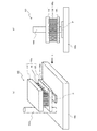
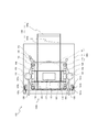
図1は、本発明の穿孔装置100を概念的に説明するための図であり、図1(a)は、この穿孔装置100の外観を示す斜視図、図1(b)は、図1(a)に示す穿孔装置100をX方向から見た構造を示す正面図である。
FIG. 1 is a diagram for conceptually explaining the
本発明は、被処理体の表面に孔を開ける穿孔針を被処理体に突き刺した状態で被処理体から穿孔針を簡単に引き抜くことができる穿孔装置を得ることを課題とし、
被処理体Pの表面に孔を穿孔する装置100であって、
被処理体Pを載置する載置台100cと、
載置台100c上に載置された被処理体Pに孔を開けるための穿孔ヘッド100aと、
穿孔ヘッド100aを載置台100cに対して進退させる穿孔ヘッド移動機構100bと
を備え、
穿孔ヘッド100aは、
ベース部材110と、
ベース部材110に固定された複数の穿孔針130と、
複数の穿孔針130が貫通可能な複数の針貫通孔120bを有する針貫通部材120と
を含む、装置を提供することにより解決したものである。
An object of the present invention is to obtain a perforating device capable of easily pulling out a perforating needle from an object to be processed in a state where a perforating needle for making a hole in the surface of the object to be processed is pierced into the object to be processed.
A
A mounting table 100c on which the object P to be processed is placed, and
A
A perforation
The
A plurality of drilling needles 130 fixed to the
It is solved by providing an apparatus including a
このような装置では、図1(a)および図1(b)に示すように、ベース部材110に固定されている複数の穿孔針130は、針貫通部材120の針貫通孔120bを貫通した状態で被処理体Pに挿入する(突き刺す)ことが可能となる。このため、針貫通部材120を介して被処理体Pに突き刺さった穿孔針130を被処理体Pから引き抜く場合、穿孔針130が針貫通部材120の針貫通孔120bに没入することにより穿孔針130は被処理体Pから確実に引き抜かれることなる。
In such a device, as shown in FIGS. 1A and 1B, a plurality of
従って、本発明の装置100は、被処理体Pに孔を開ける穿孔ヘッド130と、被処理体Pの載置台100cと、穿孔ヘッド移動機構100bとを含み、穿孔ヘッド移動機構100bが被処理体Pの載置台100cに対して穿孔ヘッド100aを進退させ、穿孔ヘッド100aは、複数の穿孔針130、ベース部材110、および針貫通部材120を含み、ベース部材110に固定された複数の穿孔針130が針貫通部材120の複数の針貫通孔120bを貫通可能に構成されているものであれば、その他の構成は、特に限定されるものではない。
Therefore, the
(被処理体P)
例えば、被処理体は、食材、樹脂材料、木材など、表面に孔を開けることが可能なものであれば任意であり得る。例えば、食材には、野菜、果物、魚体(特に焼いて調理されるための鯛、鰻、鱧など)、食用の家畜(肉鶏、豚、牛など)の肉体などが含まれる。
(Processed object P)
For example, the object to be treated may be any material such as foodstuff, resin material, wood, etc., as long as it can have holes on the surface. For example, foodstuffs include vegetables, fruits, fish (especially eels, eels, congers, etc. for baking and cooking), and edible livestock (meat chicken, pigs, beef, etc.).
(載置台100c)
載置台は、被処理体を載置することが可能な台であれば特に限定されるものではなく、任意の構成をとり得る。例えば、載置台は、移動しないベースとなる台本体のみであってもよいし、載置台がコンベアなどの移動機構を備えたものであってもよいし、載置台が回転機構を備えたものであってもよい。
(Mounting
The mounting table is not particularly limited as long as it can mount the object to be processed, and may have any configuration. For example, the mounting table may be only the base main body that does not move, the mounting table may be equipped with a moving mechanism such as a conveyor, or the mounting table may be provided with a rotating mechanism. There may be.
1つの実施形態おいて、載置台は、台本体と、台本体に回転可能に取り付けられた回転テーブルとを含み得る。この場合、載置台は、回転テーブルの回転中心が穿孔ヘッドの中心と一致するように構成されていてもよいし、回転テーブルの回転中心が穿孔ヘッドの中心からオフセットした位置となるように構成されていてもよい。ここで、穿孔ヘッドの中心は、穿孔ヘッドに固定されている複数の穿孔針130の配列の中心である。 In one embodiment, the mounting table may include a table body and a rotary table rotatably attached to the table body. In this case, the mounting table may be configured so that the center of rotation of the rotary table coincides with the center of the drilling head, or the center of rotation of the rotary table is offset from the center of the drilling head. You may be. Here, the center of the perforation head is the center of the arrangement of the plurality of perforation needles 130 fixed to the perforation head.
回転テーブルの回転角度は任意であり得る。例えば、0°〜約360°の間で任意で回転可能であってもよいし、0°〜約180°、0°〜約90°の範囲など、所定の範囲内でのみ回転(回動)するものであってもよい。 The rotation angle of the turntable can be arbitrary. For example, it may be arbitrarily rotatable between 0 ° and about 360 °, and it rotates (rotates) only within a predetermined range such as 0 ° to about 180 ° and 0 ° to about 90 °. It may be something to do.
また、駆動源は任意であり得る。例えば、電気モータ、エアモータおよび油圧モータなどの自動であってもよいし、人間の力による手動であってもよい。 Also, the drive source can be arbitrary. For example, it may be automatic such as an electric motor, an air motor and a hydraulic motor, or it may be manual by human power.
オフセットの方向や間隔は、任意であり得る。 The offset direction and spacing can be arbitrary.
なお、回転テーブルの材料は、ステンレス、銅などの金属製の本体と、本体の表面に貼り付けられた樹脂製シートとを有するものでもよいし、あるいは、回転テーブル全体が金属材料あるいは樹脂材料で形成されたものでもよいし、樹脂材料のみであってもよい。1つの実施形態において、被処理体が食材の場合は、抗菌性の高い材料であるのが好ましい。 The material of the rotary table may have a metal main body such as stainless steel or copper and a resin sheet attached to the surface of the main body, or the entire rotary table may be made of a metal material or a resin material. It may be formed or only a resin material. In one embodiment, when the object to be treated is a food material, it is preferably a material having high antibacterial properties.
また、載置台は、台本体と、台本体に設置可能な1以上のスペーサ部材とを含み得る。スペーサ部材を設けることにより、穿孔ヘッドが載置台の載置面に最接近するときの間隔を調整可能となる。 Further, the mounting table may include a table body and one or more spacer members that can be installed on the table body. By providing the spacer member, it is possible to adjust the interval when the perforated head comes closest to the mounting surface of the mounting table.
また、載置台を構成する部材は、ステンレス、銅などの金属材料を含むものでもよいし、塩化ビニール樹脂、アクリル、ABS樹脂(アクリロニトリル・ブタジエン・スチレン樹脂)、ブタジエン樹脂、PTFE樹脂などの樹脂材料を含むものでもよい。好ましい実施形態において、殺菌のための酸性またはアルカリ性の洗剤や除菌剤に対して耐性を有する塩化ビニール樹脂である。 The member constituting the mounting table may include a metal material such as stainless steel or copper, or a resin material such as vinyl chloride resin, acrylic, ABS resin (acrylonitrile, butadiene, styrene resin), butadiene resin, or PTFE resin. It may contain. In a preferred embodiment, it is a vinyl chloride resin that is resistant to acidic or alkaline detergents and disinfectants for sterilization.
(穿孔ヘッド100a)
穿孔ヘッドは、上述のとおり、ベース部材、複数の穿孔針および針貫通部材を含み、ベース部材に固定された複数の穿孔針が、針貫通部材に形成された複数の針貫通孔を貫通可能に構成されたものであれば、その他の構成は特に限定されるものではなく、任意であり得る。
(
As described above, the drilling head includes a base member, a plurality of drilling needles, and a needle penetrating member, and a plurality of drilling needles fixed to the base member can penetrate a plurality of needle penetrating holes formed in the needle penetrating member. As long as it is configured, other configurations are not particularly limited and may be arbitrary.
例えば、穿孔ヘッドを構成するベース部材は、穿孔針が固定される針取付板と、針取付板を補強する板補強材とを有するものでもよい。ここで、ベース部材、穿孔針および針貫通部材は上述した金属材料あるいは樹脂材料で構成されていてもよい。ただし、軽量化を考慮すると、針取付板は樹脂製とし、板補強材を針取付板より薄い金属製板とすることが望ましい。 For example, the base member constituting the drilling head may have a needle mounting plate to which the drilling needle is fixed and a plate reinforcing material for reinforcing the needle mounting plate. Here, the base member, the perforated needle, and the needle penetrating member may be made of the above-mentioned metal material or resin material. However, in consideration of weight reduction, it is desirable that the needle mounting plate is made of resin and the plate reinforcing material is a metal plate thinner than the needle mounting plate.
また、ベース部材に対する穿孔針の固定は、任意であり得る。例えば、ベース部材に形成した取付孔に穿孔針の一端を圧入することによる固定であってもよいし、ベース部材に形成したねじ孔に穿孔針の一端に形成した雄ねじ部をねじ込むことによる固定であってもよいし、溶接や接着剤などによる固定であってもよい。 Further, the fixing of the perforation needle to the base member may be arbitrary. For example, it may be fixed by press-fitting one end of the perforated needle into the mounting hole formed in the base member, or by screwing the male screw portion formed at one end of the perforated needle into the screw hole formed in the base member. It may be present, or it may be fixed by welding or adhesive.
ここで、穿孔針は被処理体に孔を開けることができるものであれば、具体的な構造は特に限定されるものではなく、任意である。例えば、穿孔針の断面形状は、略円形形状、略楕円形状などであってもよいし、あるいは、略三角形状、略矩形状、略多角形状などであってもよい。 Here, the specific structure of the perforation needle is not particularly limited as long as it can make a hole in the object to be processed, and is arbitrary. For example, the cross-sectional shape of the drilling needle may be a substantially circular shape, a substantially elliptical shape, or the like, or may be a substantially triangular shape, a substantially rectangular shape, a substantially polygonal shape, or the like.
また、穿孔針の孔(外径)の大きさは、被処理体の種類や大きさに応じて任意であり得る。1つの実施形態において、被処理体を鰻などの食材とした場合には、孔の大きさは約0.1mm〜約1.0mm、好ましくは約0.2mm〜約0.8mm、さらに好ましくは約0.3mm〜約0.5mmであり得る。外径が約0.1mmより小さいと強度が弱く容易に針が折れてしまう。また、外径が約1.0mm以上だと被処理体の表面に孔が設けられたことが確認できてしまい、被処理体が特に食材などの場合、見栄えが悪くまる。さらに、必要以上に被処理体の養分などが外部に漏出してしまうという問題が生じる。 Further, the size of the hole (outer diameter) of the drilling needle may be arbitrary depending on the type and size of the object to be processed. In one embodiment, when the object to be treated is a food material such as eel, the size of the holes is about 0.1 mm to about 1.0 mm, preferably about 0.2 mm to about 0.8 mm, and more preferably. It can be from about 0.3 mm to about 0.5 mm. If the outer diameter is smaller than about 0.1 mm, the strength is weak and the needle easily breaks. Further, if the outer diameter is about 1.0 mm or more, it can be confirmed that holes are provided on the surface of the object to be processed, and when the object to be processed is a food material or the like, the appearance is deteriorated. Further, there arises a problem that nutrients and the like of the object to be treated leak to the outside more than necessary.
また、複数設けられる穿孔針の孔の数や孔間の間隔についても、被処理体の種類や大きさに応じて任意であり得る。1つの実施形態において、被処理体を鰻などの食材とした場合には、隣接する孔の間隔は、穿孔針の孔(外径)の約2倍〜約5倍であり得る。さらに、好ましい実施形態において、複数設けられる穿孔針の配置は千鳥状である。 Further, the number of holes of the plurality of perforated needles and the spacing between the holes may be arbitrary depending on the type and size of the object to be processed. In one embodiment, when the object to be treated is a food material such as eel, the distance between adjacent holes may be about 2 to about 5 times the hole (outer diameter) of the perforated needle. Further, in a preferred embodiment, the arrangement of the plurality of perforated needles is staggered.
なお、穿刺針の断面形状が矩形状である場合、針と針との間隔は、穿刺針の長手方向の長さと同じもしくはそれよりも広くするのが好ましい。穿刺針の断面形状が矩形状である場合、針と針との間隔は、穿刺針の長手方向の長さよりも狭くすると、穿刺針を被処理体へ押圧する際の力が大きくなり、手動での作業が困難になる。 When the cross-sectional shape of the puncture needle is rectangular, the distance between the needles is preferably the same as or wider than the length in the longitudinal direction of the puncture needle. When the cross-sectional shape of the puncture needle is rectangular, if the distance between the needles is narrower than the longitudinal length of the puncture needle, the force for pressing the puncture needle against the object to be processed increases, and the force is manually increased. Work becomes difficult.
さらに、穿孔ヘッドは、複数の穿孔針が針貫通部材の複数の針貫通孔から出没可能となるようにベース部材と針貫通部材とを連結する連結機構を有するものでもよい。なお、このようにベース部材と針貫通部材とを連結する連結機構は、穿孔ヘッドではなく、穿孔ヘッド移動機構に設けられていてもよい。すなわち、穿孔ヘッド移動機構が、ベース部材と針貫通部材とが連結されるように穿孔ヘッドを支持するように構成されていてもよい。 Further, the drilling head may have a connecting mechanism for connecting the base member and the needle penetrating member so that the plurality of drilling needles can appear and disappear from the plurality of needle penetrating holes of the needle penetrating member. The connecting mechanism for connecting the base member and the needle penetrating member in this way may be provided not in the drilling head but in the drilling head moving mechanism. That is, the drilling head moving mechanism may be configured to support the drilling head so that the base member and the needle penetrating member are connected.
また、穿孔ヘッドは、ベース部材を振動させる振動発生器をさらに含むものであってもよい。ベース部材を振動させることにより、穿孔針も振動することとなり、被処理体に穿孔針が刺さり易くなる。なお、振動する方向は任意であり得る。例えば、穿孔ヘッドが進退する方向に沿った方向であってもよいし、穿孔ヘッドが進退する方向とは異なる方向(例えば、直行する方向)に振動させてもよい。 Further, the drilling head may further include a vibration generator that vibrates the base member. By vibrating the base member, the perforation needle also vibrates, which makes it easier for the perforation needle to pierce the object to be processed. The direction of vibration can be arbitrary. For example, the perforation head may be vibrated in a direction along the advancing / retreating direction, or may be vibrated in a direction different from the direction in which the perforation head advances / retreats (for example, in a orthogonal direction).
さらに、穿孔ヘッドが振動発生器を有する場合、穿孔ヘッドは、複数の穿孔針が針貫通部材の複数の針貫通孔から出没可能となるようにベース部材と針貫通部材とを連結する連結機構をさらに備え、穿孔装置は、複数の穿孔針が複数の針貫通孔から突出したとき振動発生器を動作させる駆動手段を有することが好ましい。 Further, when the drilling head has a vibration generator, the drilling head has a connecting mechanism for connecting the base member and the needle penetrating member so that the plurality of drilling needles can appear and disappear from the plurality of needle penetrating holes of the needle penetrating member. Further, the drilling device preferably has a driving means for operating the vibration generator when the plurality of drilling needles protrude from the plurality of needle through holes.
このような構成とすることにより、針貫通部材を貫通した穿孔針が被処理体に接触した時点で穿孔針が自動的に振動することとなり、穿孔針の無駄な振動を防止でき、作業コストの低減を行うことが可能となる。 With such a configuration, the perforated needle automatically vibrates when the perforated needle penetrating the needle penetrating member comes into contact with the object to be processed, and unnecessary vibration of the perforated needle can be prevented, and the work cost can be reduced. It is possible to reduce the amount.
(穿孔ヘッド移動機構100b)
穿孔ヘッド移動機構は、穿孔ヘッドを載置台に対して進退させるものであれば具体的な構成は限定されるものではなく、任意であり得る。
(Punching
The specific configuration of the perforation head moving mechanism is not limited as long as the perforation head is moved back and forth with respect to the mounting table, and may be arbitrary.
穿孔ヘッド移動機構は、例えば、穿孔ヘッドを載置台上で鉛直方向に平行移動させるものでもよいし、穿孔ヘッドを載置台上で水平な回転軸の周りに回転移動させるものでもよい。なお、穿孔ヘッド移動機構の駆動源は任意であり得る。例えば、電気モータ、エアモータおよび油圧モータなどの自動であってもよいし、人間の力による手動であってもよい。 The drilling head moving mechanism may, for example, move the drilling head vertically on the mounting table in parallel, or may rotate the drilling head around a horizontal rotation axis on the mounting table. The drive source of the drilling head moving mechanism may be arbitrary. For example, it may be automatic such as an electric motor, an air motor and a hydraulic motor, or it may be manual by human power.
さらに、穿孔ヘッド移動機構は、載置台からの穿孔ヘッドの距離(ヘッド離間距離)に応じた方向に穿孔ヘッドを付勢する付勢手段を有していてもよい。例えば、常に載置台からの穿孔ヘッドの距離が遠くなる方向に付勢力を生じる付勢手段であってもよいし、常に
載置台からの穿孔ヘッドの距離が近づく方向に付勢力を生じる付勢手段であってもよいし、載置台と穿孔ヘッドとの距離に応じて付勢力が変化する付勢手段であってもよい。
Further, the drilling head moving mechanism may have a urging means for urging the drilling head in a direction corresponding to the distance of the drilling head from the mounting table (head separation distance). For example, it may be an urging means that always generates an urging force in a direction in which the distance of the drilling head from the mounting table increases, or an urging means that always generates an urging force in a direction in which the distance of the drilling head from the mounting table approaches. It may be an urging means whose urging force changes according to the distance between the mounting table and the drilling head.
例えば、常に載置台からの穿孔ヘッドの距離が遠くなる方向に付勢力を生じる付勢手段の場合は、操作者の意図に反して穿孔ヘッドが載置台に近づかないので高い安全性を得ることが可能となる。 For example, in the case of an urging means that always generates an urging force in a direction in which the distance of the drilling head from the mounting table is long, the drilling head does not approach the mounting table against the intention of the operator, so that high safety can be obtained. It will be possible.
また、常に載置台からの穿孔ヘッドの距離が近づく方向に付勢力を生じる付勢手段の場合は、作業者などの穿孔ヘッドを載置台に近づける際の力を軽減することが可能となる。 Further, in the case of an urging means that always generates an urging force in a direction in which the distance of the drilling head from the mounting table is approaching, it is possible to reduce the force when the drilling head of an operator or the like is brought closer to the mounting table.
また、載置台と穿孔ヘッドとの距離に応じて付勢力が変化する付勢手段(例えば、穿孔ヘッドの穿孔針が被処理体に接触する近傍の位置まで穿孔ヘッドを移動する距離においては、載置台からの穿孔ヘッドの距離が遠のく方向に付勢力を生じさせ、穿孔ヘッドの穿孔針が被処理体に接触する近傍の位置では、付勢力が消失し、穿孔ヘッドの穿孔針が被処理体に接触した位置から被処理体内部に差し込まれる位置まで移動する距離においては、載置台からの穿孔ヘッドの距離が近づく方向に付勢力を生じさせる)とすることにより、安全性を保ちつつ作業力を軽減することが可能となる。 Further, the urging means whose urging force changes according to the distance between the mounting table and the piercing head (for example, at a distance for moving the piercing head to a position near the piercing needle of the piercing head in contact with the object to be processed, the mounting is performed. An urging force is generated in the direction in which the perforation head is farther from the pedestal, and the urging force disappears at a position near the perforation needle of the perforation head in contact with the object to be processed, and the perforation needle of the perforation head becomes the object to be processed. In the distance that moves from the contacted position to the position where it is inserted into the object to be processed, an urging force is generated in the direction in which the distance of the drilling head from the mounting table approaches), so that the working force can be maintained while maintaining safety. It is possible to reduce it.
具体的には、付勢手段は、例えば、穿孔ヘッドが載置台から第一の距離の位置である状態では、穿孔ヘッドの自重に対抗して穿孔ヘッドが上昇するように、穿孔ヘッドに接続された操作アームを付勢する。 Specifically, the urging means is connected to the perforation head so that, for example, when the perforation head is at a position of the first distance from the mounting table, the perforation head rises against its own weight. Bounce the operating arm.
付勢手段は、穿孔ヘッドが載置台から第一の距離よりも短い第二の距離の位置である状態では、操作アームに対する付勢力を消失する。 The urging means loses the urging force on the operating arm when the perforation head is at a position of a second distance shorter than the first distance from the mounting table.
付勢手段は、穿孔ヘッドが載置台から第二の距離よりも短い第三の距離の位置である状態では、穿孔ヘッドが下降するように穿孔ヘッドに接続された操作アームを付勢するものである。ここで、第一の距離の位置、第二の距離の位置、第三の距離の位置は以下の通り定義する。 The urging means urges the operation arm connected to the piercing head so that the piercing head descends when the piercing head is at a position of a third distance shorter than the second distance from the mounting table. is there. Here, the position of the first distance, the position of the second distance, and the position of the third distance are defined as follows.
ここで、第二の距離の位置は、穿孔ヘッドの針貫通部材が被処理体に接触する近傍の位置にあるときの穿孔ヘッドの位置とする。 Here, the position of the second distance is the position of the drilling head when the needle penetrating member of the drilling head is in the vicinity of contact with the object to be processed.
第一の距離の位置は、穿孔ヘッドが第二の距離の位置にあるときよりも、穿孔ヘッドの針貫通部材が載置台から離れているときの穿孔ヘッドの位置とする。 The position of the first distance is the position of the drilling head when the needle penetrating member of the drilling head is farther from the mounting table than when the drilling head is at the position of the second distance.
第三の距離の位置は、穿孔ヘッドが第二の距離の位置にあるときと穿孔ヘッドの針貫通部材と載置台との距離は同じであるが、穿孔ヘッドのベース部材の位置が、穿孔ヘッドが第二の距離の位置にあるときよりも載置台に近い位置にあるときの穿孔ヘッドの位置とする。 The position of the third distance is the same as when the drilling head is at the position of the second distance and the distance between the needle penetrating member of the drilling head and the mounting table, but the position of the base member of the drilling head is the same as that of the drilling head. Is the position of the drilling head when it is closer to the mounting table than when it is at the second distance position.
以下、本発明の実施形態について図面を参照しながら説明する。 Hereinafter, embodiments of the present invention will be described with reference to the drawings.
なお、実施形態1では、本発明の穿孔装置(被処理体の表面に孔を穿孔する装置)の一例として、処理の対象である被処理体が鮮魚(具体的には、鰻のかば焼きの素材である鰻の生の魚体)であり、載置台が台本体と回転テーブルとを有し、穿孔ヘッドが振動発生器を有し、穿孔ヘッドのベース部材が針取付板と板補強材とを有し、穿孔ヘッド移動機構が穿孔ヘッドを載置台上で鉛直方向に移動させるものを挙げる。さらに、実施形態1の穿孔ヘッド移動機構は、載置台からの穿孔ヘッドの距離に応じた方向に穿孔ヘッドを付勢する付勢手段を有するものとする。 In the first embodiment, as an example of the perforation device of the present invention (a device for perforating holes on the surface of the object to be treated), the object to be treated is a fresh fish (specifically, a material for eel kabayaki). The eel's raw fish body), the mounting table has a base body and a rotary table, the perforation head has a vibration generator, and the base member of the perforation head has a needle mounting plate and a plate reinforcing material. Then, the drilling head moving mechanism moves the drilling head vertically on the mounting table. Further, the drilling head moving mechanism of the first embodiment shall have a urging means for urging the drilling head in a direction corresponding to the distance of the drilling head from the mounting table.
また、実施形態2では、本発明の穿孔装置(被処理体の表面に孔を穿孔する装置)の他の例として、実施形態1の穿孔装置の載置台に代わる、台本体とスペーサ部材とを有する載置台を備え、さらに、実施形態1の穿孔装置の穿孔ヘッド移動機構に代わる、穿孔ヘッドを載置台上で回転移動させる穿孔ヘッド移動機構を備えた穿孔する装置を挙げる。実施形態2の穿孔ヘッド移動機構は、実施形態1の付勢手段とは異なり、穿孔ヘッドをその自重に対抗して穿孔ヘッドを載置台から常に遠ざける方向に付勢する付勢手段を有するものとする。 Further, in the second embodiment, as another example of the drilling device of the present invention (a device for drilling holes in the surface of the object to be processed), a table body and a spacer member are used instead of the mounting table of the punching device of the first embodiment. An example of a perforating device is provided with a mounting table having a mounting table, and further provided with a punching head moving mechanism for rotating and moving the punching head on the mounting table, instead of the punching head moving mechanism of the punching device of the first embodiment. Unlike the urging means of the first embodiment, the perforation head moving mechanism of the second embodiment has an urging means for urging the perforation head in a direction in which the perforation head is always kept away from the mounting table against its own weight. To do.
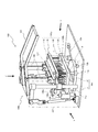
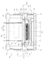
(実施形態1)
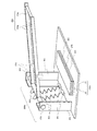
図2は、本発明の実施形態1による穿孔装置100を説明するための斜視図であり、穿孔スタンバイ状態の穿孔装置100の外観を示している。
(Embodiment 1)
FIG. 2 is a perspective view for explaining the
実施形態1の穿孔装置100は、鰻などの魚体である被処理体Pの表面に孔を穿孔する装置である。このように魚を焼く前に魚体の表皮を貫通する孔を開けるのは、魚を焼いている間に魚体内部で生ずるガスをその孔から逃がすためであり、魚を焼いている間に魚体内部で生ずるガスを逃がすことで、焼き魚の表皮の剥離を回避することができ、見栄えのよい焼き魚料理を提供することができるからである。
The
この穿孔装置100は、図2に示すように、被処理体Pを載置する載置台100cと、載置台100c上に載置された被処理体Pに孔を開けるための穿孔ヘッド100aと、穿孔ヘッド100aを載置台100cに対して進退させる穿孔ヘッド移動機構100bとを備えている。
As shown in FIG. 2, the
穿孔ヘッド100aは、図2に示すように、ベース部材110と、ベース部材110に固定された複数の穿孔針130と、複数の穿孔針130が貫通可能な複数の針貫通孔120bを有する針貫通部材120とを含む。
As shown in FIG. 2, the
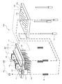
図3は、図2に示す穿孔装置100の載置台100cおよび穿孔ヘッド移動機構100bを説明するための斜視図であり、穿孔装置100から穿孔ヘッド100aを取り外した状態を示している。
FIG. 3 is a perspective view for explaining the mounting table 100c and the drilling
(載置台100c)
ここで、載置台100cは、穿孔装置100の土台となる基部11と、基部11上に回転可能に取り付けられた回転テーブル12とを含み、回転テーブル12の回転中心Rcは、穿孔ヘッド110aの中心からオフセットした位置となるように構成されている。ここで、穿孔ヘッド110aの中心は、ベース部材110に固定されている複数の穿孔針130の配列の中心(言い換えると、針貫通部材120に形成されている複数の針貫通孔120bの配列の中心Rc0(図6(b)参照))である。例えば、複数の穿孔針130の配列が、行方向および列方向にそれぞれ一定ピッチで配置されている場合、複数の穿孔針130が配列されている領域は長方形の領域となり、複数の穿孔針130の配列中心はその配列領域の外形がなす長方形形状の中心となる。
(Mounting
Here, the mounting table 100c includes a
また、回転テーブル12は、本体(金属製の円板部材)121と表層部(樹脂製の円形シート部材)122とで構成されており、回転テーブル12の表層部121の表面は、被処理体Pを載置する載置面となっている。なお、回転テーブル12の構造は、本体121と表層部122とを有するものに限定されるものではなく、任意であり得る。回転テーブル12は、表層部である円形シート部材を含まず、1つの樹脂製の円板部材で構成されていてもよい。
Further, the rotary table 12 is composed of a main body (metal disk member) 121 and a surface layer portion (resin circular sheet member) 122, and the surface of the
回転テーブル12にはこれを回転させるための操作レバー12aが取り付けられており、穿孔装置100の土台となる基部11には、操作レバー12aに当接する一対のレバーストッパ12bが所定の間隔を隔てて取り付けられている。ここでは、回転テーブル12は操作レバー12aを一対のレバーストッパ12b間で移動させることにより約90°回転するようになっている。
An operating
また、載置台100cの台本体11の上面には、穿孔ヘッド100aの連結機構140を構成する支持支柱101を受ける支柱受ブロック11aが、支持支柱101に対向するように配置されている。
Further, on the upper surface of the
(穿孔ヘッド移動機構100b)
穿孔ヘッド移動機構100bは、載置台100cの基部11上で起立するように基部11に固定された一対の支持支柱101と、支持支柱101の先端に固定された固定ボス101aと、固定ボス101aに固着された固定アーム106とを有する。ここで、各支持支柱101は円柱体で構成されているが、角柱体で構成されていてもよいし、あるいは中実の柱材に代わる中空の管材で構成されていてもよい。
(Punching
The perforation
ここで、各支持支柱101の下端部は、載置台100cの基部11である金属製ベース板に溶接、ねじ構造などで固着されている。なお、このねじ構造は、支持支柱101の下端部に形成した雄ねじ部を載置台100cの基部11に形成したねじ孔に螺合することにより、支持支柱101を載置台100cの基部11に固着する構造である。また、各支持支柱101の上端部には固定ボス101aが、ねじ、接着剤、あるいは溶接などにより固着されている。各支持支柱101の固定ボス101aの側面には固定アーム106の一端部が溶接など固着されており、一対の固定アーム106の他端部には、これらに跨る回動シャフト102が回転可能に取り付けられている。
Here, the lower end of each
また、穿孔ヘッド移動機構100bは、穿孔ヘッド100aを載置台100c上で昇降させるための昇降ロッド105と、昇降ロッド105に接続された操作アーム104と、穿孔ヘッド100a(具体的には、穿孔ヘッド100aを構成するベース部材110)の昇降位置に応じた方向に穿孔ヘッド100aを付勢する付勢手段107とを含む。
Further, the perforation
操作アーム104は、アームフレーム部104bとアーム把持部104aとを含み、操作アーム104のアームフレーム部104bの中間部位には昇降ロッド105の一端部(上端部)がボルトナットで回動可能に連結されており、昇降ロッド105の他端部(下端部)は、穿孔ヘッド100aの連結ブラケット116にボルトナットで回動可能に連結されている。
The
さらに、付勢手段107は、回動シャフト102を回動させる付勢アーム107aと、載置台100cの台本体11に固着された取付ブラケット107cと、伸びる方向に付勢力を発生する付勢シリンダ107bとを含む。また、付勢シリンダ107bは、シリンダ本体71と、シリンダ本体71から突出する伸長ロッド72とを含み、伸長ロッド72がシリンダ本体71から突出する方向の付勢力を発生するように構成されている。ここで、付勢アーム107aの一端部(上端部)は、溶接などにより回動シャフト102の一端に固着されており、付勢アーム107aの他端部(下端部)は、付勢シリンダ107bのシリンダ本体71の一端部が接続され、取付ブラケット107cには、シリンダ本体71の他端から突出する伸長ロッド72の先端部が接続されている。
Further, the urging means 107 includes an urging
このような構成の付勢手段107を備えた穿孔ヘッド移動機構100bでは、付勢手段107は以下の機能を有することとなる。
In the drilling
穿孔ヘッド100aのベース部材110が載置台100cから離れて両者の距離が第一の距離D1となる状態(図10参照)では、付勢手段107は、穿孔ヘッド100aの自重に対抗して穿孔ヘッド100aが上昇するように操作アーム104を付勢する。なぜなら、穿孔ヘッド移動機構100bは、穿孔ヘッド100aのベース部材110と載置台100cとの離間距離が距離D1である場合には、付勢アーム107aの中心軸L1と付勢シリンダ107bの中心軸L2とが所定の角度をなすように設計されていることから、この状態で、付勢手段107の伸長ロッド72が伸びると、回動シャフト102には図10の紙面の左回りのモーメントが働き、これにより回動シャフト102に固定されている操作アーム104が昇降ロッド105を引き上げるからである。
In a state where the
穿孔ヘッド100aのベース部材110が載置台100cから第一の距離D1よりも短い第二の距離D2の位置である状態(図8参照)では、付勢手段107は、操作アーム104に対する付勢力を消失する。なぜなら、穿孔ヘッド移動機構100bは、穿孔ヘッド100aのベース部材110と載置台100cとの離間距離が距離D2(<D1)である場合には、付勢アーム107aの中心軸L1と付勢シリンダ107bの中心軸L2とが一直線上に並ぶように設計されていることから、この状態で、付勢手段107の伸長ロッド72が伸びようとしても、回動シャフト102には図8の紙面の右回りおよび左回りのいずれのモーメントも発生せず、その結果、回動シャフト102に回転可能に取り付けられている操作アーム104に対する付勢手段107による付勢力は発生しないからである。また、ここではベース部材110と針貫通部材120とを連結する連結機構140は、穿孔ヘッド100aのベース部材110が載置台100cから第二の距離D2にある状態では、針貫通部材120が被処理体Pに当接する近傍の位置に位置するように構成されている。
In a state where the
さらに、穿孔ヘッド100aのベース部材110が載置台100cから第二の距離よりも短い第三の距離D3(<D2)の位置である状態(図11参照)では、付勢手段107は、穿孔ヘッド100aが下降するように操作アーム104を付勢する。なぜなら、穿孔ヘッド移動機構100bは、穿孔ヘッド100aのベース部材110と載置台100cとの離間距離が距離D3である場合には、付勢アーム107aの中心軸L1と付勢シリンダ107bの中心軸L2とが所定の角度をなすように設計されていることから、この状態で、付勢手段107の伸長ロッド72が伸びると、回動シャフト102には図11の紙面の右回りのモーメントが働き、これにより回動シャフト102に固定されている操作アーム104が昇降ロッド105を押し下げるからである。
Further, in a state where the
なお、穿孔ヘッド移動機構100bを構成する部材、すなわち、支持支柱101、固定ボス101a、固定アーム106、回動シャフト102、昇降ロッド105、操作アーム104、付勢アーム107a、付勢手段107、および取付ブラケット107cは、強度の観点からは、上述したステンレスなどの金属材料で構成するのが好ましいが、軽量化の観点からは、金属に比べて軽量である上述した樹脂材料であってもよい。
The members constituting the drilling
(穿孔ヘッド100a)
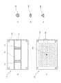
図4は、図2に示す穿孔装置100の穿孔ヘッド100aを説明するための斜視図であり、図4(a)は、穿孔装置100から取り外した穿孔ヘッド100aを示し、図4(b)は、穿孔ヘッド100aにおける連結機構140(一点鎖線で囲まれた部分)を示している。図5は、図4(a)に示す穿孔ヘッド100aを個々の部品に分解して示す斜視図である。
(
4A and 4B are perspective views for explaining the
穿孔ヘッド100aは、ベース部材110と、ベース部材110に固定された複数の穿孔針130と、複数の穿孔針130が貫通可能な複数の針貫通孔120bを有する針貫通部材120と、複数の穿孔針130が針貫通部材120の複数の針貫通孔120bから出没可能となるようにベース部材110と針貫通部材120とを連結する連結機構140とを含む。さらに、穿孔ヘッド100aは、ベース部材110を振動させる振動発生器117を含んでおり、穿孔装置100には、図2に示すように、複数の穿孔針130が複数の針貫通孔120bから突出したとき振動発生器117を動作させる駆動手段108が設けられている。以下、穿孔ヘッド100aを構成する部材について具体的に説明する。
The
(ベース部材110)
図6は、図4(a)に示す穿孔ヘッド100aの部品を説明するための平面図であり、図6(a)は、穿孔ヘッド100aのベース部材110を示す。
(Base member 110)
FIG. 6 is a plan view for explaining the parts of the
ベース部材110は、図4および図5に示すように、針取付板111と、板補強材112と、可動ボス113と、固定ブラケット114と、補強リブ115と、連結ブラケット116とを有している。板補強材112には振動発生器117が取り付けられている。
As shown in FIGS. 4 and 5, the
針取付板111の下面には、複数の穿孔針130を取り付けるための複数の針取付孔(図示せず)が形成されており、各穿孔針130の上端部が対応する針取付孔に圧入などの方法で固定されている。穿孔針130と針取付板111の針取付孔との固定は圧入による固定に限定されず、接着剤による固定でもよい。
A plurality of needle mounting holes (not shown) for mounting the plurality of
また、針取付板111には板補強材112が貼り付けられており、ここでは、針取付板111および板補強材112はそれぞれ長方形の金属製板部材で構成されている。なお、針取付板111および板補強材112はそれぞれ樹脂製板部材で構成されていてもよいし、針取付板111および板補強材112の一方が金属製板部材で構成され、その他方が樹脂製板部材で構成されていてもよい。
Further, a
また、板補強材112の上面には、対向するように一対の補強リブ115が溶接などで板補強材112の長手方向に沿って取り付けられており、対向する一対の補強リブ115の間には、所定の間隔を隔てて一対の連結ブラケット116が溶接などで固定されている。一対の補強リブ115の間であって一対の連結ブラケット116の間には、ベース部材110に振動を与える振動発生器117が設けられており、振動発生器117はベース部材110の板補強材112に固定されている。
Further, a pair of reinforcing
さらに、針取付板111には、振動発生器117を動作させる駆動手段108の操作片108bを押圧する押圧レバー108aが取り付けられている。押圧レバー108aは、穿孔針130が針貫通部材120から突出するようにベース部材110が載置台100cに近づいたときに、駆動手段108の操作片108bに当接して振動発生器117が動作するように操作片108bに対して位置決めされている。このため、穿孔針130が被処理体Pに押し付けられた状態で、穿孔針130が自動的に振動することとなり、穿孔針30の無駄な振動を防止でき、作業コストの低減が可能となる。
Further, a
さらに、板補強材112の長手方向の両端には、固定ブラケット114を介して可動ボス113が取り付けられている。可動ボス113は円管部材で構成されており、可動ボス113は、穿孔ヘッド移動機構100bにおける支持支柱101に沿って上下方向に移動可能になるように支持支柱101に取付けられるものである。
Further,
板補強材112には、図5および図6(a)に示すように、支柱挿入孔120aが板補強材112の四隅に位置するように形成されており、針取付板111にもこの支柱挿入孔112aに対応する位置に支柱挿入孔(図示せず)が形成されている。
As shown in FIGS. 5 and 6 (a), the
(針貫通部材120)
針貫通部材120は、図5および図6(b)に示すように、これを構成する金属製板部材の四隅に支柱挿入孔120aが形成され、さらに、金属製板部材の全体に渡って複数の穿孔針130を貫通させる複数の針貫通孔120bが形成されている。
(Needle penetrating member 120)
As shown in FIGS. 5 and 6B, the
(穿孔針130)
穿孔針130は、ステンレスなどの金属製の針状部材で構成されており、図6(c)に示すように円形の断面形状を有する。なお、穿孔針130は、アクリルなどの硬質の樹脂製の針状部材であってもよい。また、穿孔ヘッド100aは、円形の断面形状を有する穿孔針130に代えて図6(d)に示す楕円の断面形状を有する針状部材130aであってもよいし、あるいは、図6(e)に示す正三角形の断面形状を有する針状部材130bであってもよい。
(Punching needle 130)
The
(連結機構140)
ベース部材110は、複数の穿孔針130を貫通させる複数の針貫通孔120bが形成された針貫通部材120が連結機構140により連結されている。
(Connecting mechanism 140)
In the
ここで、連結機構140は、複数の穿孔針130が針貫通部材120の複数の針貫通孔120bから出没可能となるようにベース部材110と針貫通部材120とを連結している。
Here, the connecting
連結機構140は、具体的には、図4(b)および図5に示すように、連結支柱141と、復帰ばね142と、固定ナット143とを含み、支持支柱101は、図4(b)に示すように、大径部141aと小径部141bとを有する。
Specifically, as shown in FIGS. 4 (b) and 5, the connecting
支持支柱101の大径部141aは、針貫通部材120の支柱挿入孔120a、ベース部材110の針取付板111の支柱挿入孔112a、およびベース部材110の板補強材112の支柱挿入孔(図示せず)に挿入できない太さを有し、支持支柱101の小径部142は、これらの挿入孔に挿入可能な太さを有する。
The large-
復帰ばね142は、支持支柱101の小径部142に取り付けられており、支持支柱101が針貫通部材120およびベース部材110に取り付けられた状態では、復帰ばね142は針貫通部材120とベース部材110との間に位置するように配置され、支持支柱101の小径部141bが、ベース部材110から抜けないように、支持支柱101の小径部141bの上端に固定ナット143が取り付けられる。
The
なお、針取付板111は上述した樹脂材料で構成されており、板補強材112は上述した金属材料で構成されているが、ベース部材110は、針取付板111が金属材料で構成され、板補強材112を含まないものでもよい。その場合は、連結ブラケット116は針取付板111の上面に取り付けられることとなる。
The
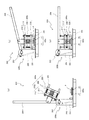
なお、図7〜図9は、図2に示す穿孔装置100の具体的な構造を示す図であり、図2に示す穿孔スタンバイ状態の穿孔装置100をZ方向から見た構造を示す上面図、図8は、図2に示す穿孔スタンバイ状態の穿孔装置100をY方向から見た側面図、図9は、図2に示す穿孔スタンバイ状態の穿孔装置100をX方向から見た構造を示す正面図である。
7 to 9 are views showing a specific structure of the
これらの図7〜図9では、図2〜図6で説明した穿孔装置100を構成する各部材のレイアウトがより精細に示されている。
In these FIGS. 7 to 9, the layout of each member constituting the
次に実施形態1の穿孔装置100の動作を説明する。
Next, the operation of the
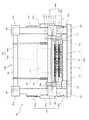
図10〜図12はそれぞれ、図2に示す穿孔装置100の具体的な構造を説明するための図であり、図10は、図8に示す穿孔スタンバイ状態の穿孔装置100に代えて、載置台100c上に被処理体Pを載置可能な穿孔待機状態の穿孔装置100を示す側面図、図11および図12は、図8に示す穿孔スタンバイ状態の穿孔装置100に代えて、載置台100c上に載置された被処理体Pに穿孔針130を突き刺した作動状態の穿孔装置100を示す側面図および正面図である。
10 to 12 are views for explaining a specific structure of the
(穿孔装置100の待機状態)
穿孔装置100の待機状態では、穿孔ヘッド100aは、図10に示すように、穿孔ヘッド移動機構100bにより支持支柱101の最上端まで持ち上げられている。この待機状態では、載置台100cの上方にはスペースが広がっており、穿孔ヘッド100aが載置台100c上に被処理体Pを載置する作業の邪魔にならないようになっている。
(Standby state of drilling device 100)
In the standby state of the
また、この待機状態では、付勢手段107の付勢シリンダ107bの中心軸L2は、付勢アーム107aの中心軸L1に対して所定の角度をなしている。すなわち、付勢シリンダ107bの下端と付勢アーム107aの上端とを結ぶ直線の右側に、付勢シリンダ107bと付勢アーム107aとの接続点が位置するようになる。このため、付勢シリンダ107bの伸長ロッド72が突出する突出力が回動シャフト102の左回転の回転力となり、この回転力が操作アーム104を持ち上げる付勢力として操作アーム104に作用している。しかも、この場合、操作アーム104には、操作アーム104が昇降ロッド105を介して穿孔ヘッド100aの自重を支えることができる程度の付勢力より若干大きな付勢力が作用している。
Further, in this standby state, the central axis L2 of the urging
その結果、待機状態では、操作アーム104を作業者が操作しない限り、穿孔ヘッド100aは、付勢手段107による操作アーム104に対する付勢力により支持支柱101の最上端付近に保持される。したがって、意図せずに作業者などの操作により穿孔ヘッド100aを載置台に向けて下すことが防止され、安全性を向上させることが可能となる。
As a result, in the standby state, the
この待機状態で作業者が載置台100cの回転テーブル12の表面(載置面)に被処理体Pを載置し(図10参照)、操作アーム104のアーム把持部104aを持って操作アーム104を引き下げると、操作アーム104は、付勢手段107による操作アーム104に対する付勢力に対向して回動シャフト102の周りで右回転することとなり、操作アーム104に昇降ロッド105を介してつながる穿孔ヘッド100aが載置台100cの回転テーブル12に向かって下降することとなる。
In this standby state, the operator places the object to be processed P on the surface (mounting surface) of the rotary table 12 of the mounting table 100c (see FIG. 10), holds the
このように操作アーム104を引き下げることで、付勢手段107の付勢シリンダ107bの中心軸L2と、付勢アーム107aの中心軸L1とがなす角度が約180°に近づくことで、付勢手段107による操作アーム104に対する付勢力が徐々に小さくなり、付勢力が穿孔ヘッド100aの自重より小さくなった後は、作業者による操作アーム104の引き下げを行わなくても、穿孔ヘッド100aはその自重により下降することとなる。その場合は、作業者は、穿孔ヘッド100aが勢いよく下降しないように操作アーム104を若干の力で上方に持ち上げるようにする必要がある。なお、操作アーム104の引き下げる力は、穿孔ヘッド100aの自重だけではなく、穿孔ヘッド100aに繋がる昇降ロッド105および操作アーム104の重さも含まれるが、ここでは、説明の都合上、操作アーム104の引き下げる力は、穿孔ヘッド100aの自重とする。
By pulling down the
その後、穿孔ヘッド100aの連結支柱141が載置台100cの支柱受ブロック11a上に着地すると、穿孔ヘッド100aの下降が停止し、図8および図9に示すように、穿孔装置100は、孔開け作業のスタンバイ状態(穿孔スタンバイ状態)となる。
After that, when the connecting
(穿孔装置100の穿孔スタンバイ状態)
この穿孔装置100の穿孔スタンバイ状態では、図8に示すように、付勢手段107の付勢シリンダ107bの中心軸L2と付勢アーム107aの中心軸L1とがなす角度はほぼ180°となっており、付勢手段107による操作アーム104に対する付勢力はほぼ働いていない状態である。
(Punching standby state of the drilling device 100)
In the drilling standby state of the
また、穿孔スタンバイ状態では、連結機構140の復帰ばね142の付勢力により、ベース部材110がその自重に対抗して針貫通部材120から一定間隔離れた位置に保持されている。これにより、穿孔スタンバイ状態では、ベース部材110に取り付けられている複数の穿孔針130は、図8および図9に示すように針貫通部材120の針貫通孔120bに没入した状態に保持される。
Further, in the drilling standby state, the
(穿孔装置100の作動状態)
この穿孔スタンバイ状態で作業者が操作アーム104のアーム把持部104aをさらに引き下げる方向に操作すると、回動シャフト102が右回転することで、昇降ロッド105が下降するとともに、付勢アーム107aが右回転する。
(Operating state of drilling device 100)
When the operator operates the
このように昇降ロッド105が下降することで、ベース部材110が図11および図12に示すように、針貫通部材120に対して近づく方向に移動し、ベース部材110に固定されている複数の穿孔針130が針貫通部材120の針貫通孔120bから突出して被処理体Pの表面に向けて移動する。このとき、付勢手段107の付勢シリンダ107bの中心軸L2と付勢アーム107aの中心軸L1とが、図11に示すように、所定の角度をなすようになる。すなわち、付勢シリンダ107bの下端と付勢アーム107aの上端とを結ぶ直線の左側に、付勢シリンダ107bと付勢アーム107aとの接続点が位置するようになる。
By lowering the elevating
これにより、付勢シリンダ107bの伸長ロッド72が突出する突出力が回動シャフト102の右回転の回転力となり、この回転力が操作アーム104を引き下げる付勢力として操作アーム104に作用する。このため、付勢手段107による操作アーム104に対する付勢力が、穿孔針130の先端が被処理体Pの表面を突き刺す力として作用し、作業者などが穿孔針130の先端を被処理体Pの表面に突き刺すのに要する操作力を軽減することが可能となる。
As a result, the protruding output from which the
また、ベース部材110の下降により複数の穿孔針130の先端が針貫通部材120の針貫通孔120bから突出すると、ベース部材110の針取付板111に取り付けられている押圧レバー108aが駆動手段108の操作片108bを押圧することとなる。これにより駆動手段108により振動発生器117が動作してベース部材110を介して穿孔針130に振動が与えられることとなる。
Further, when the tips of the plurality of
穿孔針130が被処理体Pの表面に突き刺さるときに、穿孔針130が振動していることで、振動発生器117が被処理体Pの表面に突き刺さりやすくなり、穿孔針130を被処理体Pに突き刺す時の作業者の操作力が軽減される。
When the
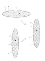
図13は、図2に示す穿孔装置100の回転テーブル12の使用方法を説明するための平面図であり、図13(a)は、基準位置にある回転テーブル12上に載置された被処理体Pと、針貫通部材120の針貫通孔120bとの位置関係を示し、図13(b)は、回転テーブル12の基準位置で被処理体Pに形成される孔H1を示す。
FIG. 13 is a plan view for explaining how to use the rotary table 12 of the
上述したように、穿孔スタンバイ状態の穿孔装置100においては、図13(a)は、基準位置にある回転テーブル12上に載置された被処理体Pと、針貫通部材120の針貫通孔120bとの位置関係は図13(a)に示すとおりであり、この状態で、操作アーム104を引き下げることにより、穿孔ヘッド100aの複数の穿孔針130が被処理体Pの表面に突き刺さることとなり、図13(b)に示すように、被処理体Pの表面に複数の孔H1が形成される。
As described above, in the
その後、作業者が操作アーム104を上方に持ち上げると、ベース部材110が針貫通部材120から遠ざかる方向に移動し、ベース部材110に取り付けられている穿孔針130が被処理体Pから引き抜かれる方向に移動する。このとき、穿孔針130が被処理体Pに突き刺さったまま穿孔針130と被処理体Pとがともに上方に移動したとしても、被処理体Pは針貫通部材120に当接することで、被処理体Pは穿孔針130から払い落とされることとなる。これにより、穿孔針130を被処理体Pから容易に引き抜くことができる。
After that, when the operator lifts the
そして、操作アーム104を穿孔装置100のスタンバイ状態の位置まで戻した後、回転テーブル12の操作レバー12aを、操作レバー12aが一方のレバーストッパ12bから操作レバー12aが他方のレバーストッパ12bに当接する状態になるように操作し、再度、操作アーム104を引き下げる操作を行う。
Then, after returning the
図13(c)は、回転位置にある回転テーブル12上に載置された被処理体Pと、針貫通部材120の針貫通孔120bとの位置関係を示し、図13(d)は、回転テーブル12の回転位置で被処理体Pに形成される孔H2を示す。
FIG. 13 (c) shows the positional relationship between the object to be processed P placed on the rotary table 12 at the rotation position and the
図13(c)に示すように、スタンバイ状態の穿孔装置100において、回転テーブル12を回転させた後に、操作アーム104を再度引き下げることにより、穿孔ヘッド100aの複数の穿孔針130が被処理体Pの表面に突き刺さることとなり、被処理体Pの表面には、図13(b)に示すように、既に形成されている複数の孔H1とは異なる位置に複数の孔H2が形成される。
As shown in FIG. 13C, in the
図14は、回転テーブル12の基準位置で被処理体Pに形成される孔H1(実線表示)と、回転テーブル12の回転位置で被処理体Pに形成される孔H2(点線表示)とを重ね合わせて示す図である。 FIG. 14 shows a hole H1 (solid line display) formed in the object to be processed P at the reference position of the rotary table 12 and a hole H2 (dotted line display) formed in the object P to be processed at the rotation position of the rotary table 12. It is the figure which shows by superimposing.
このように、回転テーブル12の基準位置で被処理体Pの表面に孔を開ける作業を行い、その後、回転テーブル12を回転させて回転テーブル12の回転位置で被処理体Pの表面に孔H2を開ける作業を行うことで、図14に示すように、簡単に被処理体Pの表面に多くの孔H1およびH2を形成することができる。 In this way, the work of making a hole in the surface of the object to be processed P at the reference position of the rotary table 12 is performed, and then the rotary table 12 is rotated to make a hole H2 in the surface of the object to be processed P at the rotation position of the rotary table 12. As shown in FIG. 14, many holes H1 and H2 can be easily formed on the surface of the object to be processed P by performing the work of opening.
オフセットすることにより、被処理体に穿刺する針が常に同じ位置の針だけではなくなるため、複数の針が均等に使用されるため、針の切れ味を持続させることが可能となる。 By offsetting, the needles that puncture the object to be processed are not always the needles at the same position, so that a plurality of needles are used evenly, and the sharpness of the needles can be maintained.
また、穿孔針130の断面形状を略円形や正方形以外の形状とした場合には、オフセットすることにより様々な模様を形成することが可能となる。
Further, when the cross-sectional shape of the
このように本実施形態1の穿孔装置100は、被処理体Pを載置する載置台100cと、載置台100c上に載置された被処理体Pの表皮に孔を開けるための穿孔ヘッド100aと、穿孔ヘッド100aを載置台100cに対して進退させる穿孔ヘッド移動機構100bとを備え、穿孔ヘッド100aは、ベース部材110と、ベース部材110に固定された複数の穿孔針130と、複数の穿孔針130が貫通可能な複数の針貫通孔120bを有する針貫通部材120とを含む。
As described above, in the
このため、実施形態1の穿孔装置100では、ベース部材110に固定されている複数の穿孔針130は、針貫通部材120の針貫通孔120bを貫通した状態で被処理体Pに突き刺さることが可能となり、被処理体Pに突き刺さった穿孔針130を被処理体Pから引き抜く場合、穿孔針130が針貫通部材120の針貫通孔120bに没入することにより穿孔針130は被処理体Pから確実に引き抜かれる。
Therefore, in the
その結果、実施形態1の穿孔装置100では、被処理体Pの表面に孔を開ける穿孔針130を被処理体Pに突き刺した状態で被処理体Pから穿孔針130を簡単に引き抜くことができる効果が得られる。
As a result, in the
また、実施形態1の穿孔装置100では、載置台100cは、回転テーブル12を含み、回転テーブル12の回転中心は、穿孔ヘッドの中心からオフセットした位置となるように構成されているので、回転テーブル12の基準位置で被処理体Pの表面に孔を開ける作業を行い、その後、回転テーブル12を回転させて、基準位置とは異なる位置で被処理体Pの表面に孔H2を開ける作業を行うことで、被処理体Pの表面に、簡単により多くの孔を形成することができる。
Further, in the
また、穿孔ヘッド移動機構100bは、載置台100cからの穿孔ヘッド100aの距離(ヘッド離間距離)に応じた方向に穿孔ヘッドを付勢する付勢手段107を有するので、穿孔ヘッド100aを載置台100cに近づける作業を行うときのヘッド離間距離と、穿孔ヘッド100aの穿孔針130を被処理体Pに差し込む作業を行うときのヘッド離間距離とが異なることから、それぞれの作業状態で作業者の操作をアシストする方向に穿孔ヘッド100aを付勢することが可能となり、穿孔作業のための操作に要する作業者などの力を軽減することができる。
Further, since the drilling
また、穿孔ヘッド100aは、複数の穿孔針130が取り付けられたベース部材110を振動させる振動発生器117を含むので、穿孔針130が被処理体Pの表面に突き刺さるときに、ベース部材110の振動によりベース部材に固定されている穿孔針130も振動させることができ、これにより被処理体Pに穿孔針130が刺さり易くなる。
Further, since the
なお、上記実施形態1では、穿孔装置100として、穿孔ヘッド100aを載置台100c上で鉛直方向に平行移動させる穿孔ヘッド移動機構100bを備えたものを示したが、穿孔ヘッド移動機構は、穿孔ヘッド100aを載置台上で水平な回転軸の周りに回転移動させる穿孔ヘッド移動機構200bでもよく、以下の実施形態2では、このような穿孔ヘッド移動機構200bを備えた穿孔装置200を説明する。
In the first embodiment, the
(実施形態2)
図15は、本発明の実施形態2による穿孔装置200を説明するための斜視図であり、穿孔装置200の外観を示している。
(Embodiment 2)
FIG. 15 is a perspective view for explaining the
実施形態2の穿孔装置200は、実施形態1の穿孔装置100と同様、鰻などの魚体である被処理体Pの表面に孔を穿孔する装置である。
The
この穿孔装置200は、図15に示すように、被処理体Pを載置する載置台200cと、載置台200c上に載置された被処理体Pに孔を開けるための穿孔ヘッド200aと、穿孔ヘッド200aを載置台200cに対して進退させる穿孔ヘッド移動機構200bとを備えている。
As shown in FIG. 15, the
ここで、穿孔ヘッド200aは、実施形態1の穿孔装置100における穿孔ヘッド100aとは、振動発生器117を有していない点以外は同一の構成を有している。また、この穿孔ヘッド200aでは、載置台200cおよび穿孔ヘッド移動機構200bは実施形態1の穿孔ヘッド100aにおけるものと異なった構成を有している。
Here, the
図16は、図15に示す穿孔装置200の穿孔ヘッド200aを支持する穿孔ヘッド移動機構200bおよび載置台200cを説明するための斜視図であり、穿孔装置200から穿孔ヘッド200aを取り外した状態を示している。
FIG. 16 is a perspective view for explaining the drilling
(穿孔ヘッド200a)
穿孔ヘッド200aは、振動発生器117を有していない点を除いて、実施形態1の穿孔ヘッド100aと同一の構成を有しており、穿孔ヘッド100aにおける針取付板111と同一構造の針取付板211と、穿孔ヘッド100aにおける板補強材112と同一構造の板補強材212と、穿孔ヘッド100aにおける複数の穿孔針130と同一構造の複数の穿孔針230とを有する。従って、この実施形態2の穿孔装置200には、実施形態1の穿孔装置100における、振動発生器117を動作させるための駆動手段108および駆動手段108をオンオフする押圧レバー108aは設けられていない。
(
The
(載置台200c)
ここで、載置台200cは、台本体21と、台本体21に設けられたスペーサ部22とを含む。スペーサ部22は、台本体21上に積み重ねる3つのスペーサ板221〜223を含み、台本体21上に積み重ねるスペーサ板の枚数により穿孔ヘッド200aが載置台200cの載置面(被処理体Pが載置される載置面)に最接近するときの間隔を調整可能としたものである。
(Mounting
Here, the mounting table 200c includes a
(穿孔ヘッド移動機構200b)
穿孔ヘッド移動機構200bは、載置台200cの台本体21上に対向するよう設けられた一対の支持支柱201と、両支持支柱201に跨るように回動可能に設けられた回動シャフト202と、回動シャフト202に取り付けられた操作アーム204とを有する。
(Punching
The perforation
ここで、回動シャフト202の一端部は、一方の支持支柱201に取り付けられた軸受け203に回動可能に支持され、回動シャフト202の他端部は、他方の支持支柱201に取り付けられた軸受け203に回動可能に支持されている。
Here, one end of the
また、操作アーム204は、一対のアームフレーム部204bとアーム把持部204aとを有し、一対のアームフレーム部204bの一端部は回動シャフト202に溶接などで固着されており、一対のアームフレーム部204bの他端部にはこれらに跨るようにアーム把持部204aが取り付けられている。一対のアームフレーム部204bの中間部分には、穿孔ヘッド200aの連結ブラケット216がボルトナットにより回転可能に連結されている。
Further, the
ここで、回動シャフト202には一対のばね支持片206が取り付けられ、載置台200cの台本体21のうちの回動シャフト202に対向する部分には、一対のばね固定片207が取り付けられ、対向するばね支持片206とばね固定片207との間には付勢ばね205が取り付けられている。この付勢ばね205は、操作アーム204に接続された穿孔ヘッド200aがその自重に対抗して持ち上げられる方向に回動シャフト202が回転するように、操作アーム204を付勢している。
Here, a pair of
次に実施形態2の穿孔装置200の動作を説明する。
Next, the operation of the
図17は、図15に示す穿孔装置200の動作を説明するための側面図であり、図17(a)は、穿孔装置200の穿孔待機状態を示し、図17(b)は、穿孔装置200の穿孔スタンバイ状態を示し、図17(c)は、穿孔装置200の穿孔作動状態を示す。
17 is a side view for explaining the operation of the
(穿孔装置200の穿孔待機状態)
穿孔装置200の穿孔待機状態では、穿孔ヘッド200aは、図17(a)に示すように、穿孔ヘッド移動機構200bにより支持支柱201の上方まで持ち上げられている。この待機状態では、載置台200cの上方にはスペースが広がっており、穿孔ヘッド200aが載置台200c上に被処理体Pを載置する作業の邪魔にならないようになっている。
(Punching standby state of the drilling device 200)
In the drilling standby state of the
この状態では、操作アーム204には、付勢ばね205による付勢力として、操作アーム204が穿孔ヘッド200aを支えることができる程度の付勢力より若干大きな作用している。
In this state, the
その結果、待機状態では、操作アーム204を作業者が操作しない限り、穿孔ヘッド200aは、付勢ばね205による操作アーム204に対する付勢力により支持支柱201の上方に保持される。
As a result, in the standby state, the
この穿孔待機状態で作業者が載置台200cの表面(載置面)に被処理体Pを載置し(図17(a)参照)、操作アーム204のアーム把持部204aを持って操作アーム204を引き下げると、操作アーム204は、付勢ばね205による操作アーム204に対する付勢力に対向して回動シャフト202の周りで右回転することとなり、操作アーム204に連結ブラケット216を介してつながる穿孔ヘッド200aが載置台200c上に向かって下降することとなる。
In this drilling standby state, the operator places the object to be processed P on the surface (mounting surface) of the mounting table 200c (see FIG. 17A), holds the
そして、穿孔ヘッド200aの連結支柱241が載置台200c上に着地すると、穿孔ヘッド200aの下降が停止し、図17(b)に示すように、穿孔装置200は、孔開け作業の穿孔スタンバイ状態となる。
Then, when the connecting
(穿孔装置200の穿孔スタンバイ状態)
この穿孔スタンバイ状態では、ベース部材210に取り付けられている複数の穿孔針230は、図17(b)に示すように針貫通部材220の針貫通孔(図示せず)に没入した状態に保持される。
(Punching standby state of the drilling device 200)
In this drilling standby state, the plurality of drilling needles 230 attached to the
(穿孔装置200の作動状態)
この穿孔スタンバイ状態で作業者が操作アーム204のアーム把持部204aをさらに引き下げる方向に操作すると、回動シャフト202が右回転することで、連結ブラケット216が下降する。これにより、ベース部材210の下降により複数の穿孔針230の先端が針貫通部材220の針貫通孔(図示せず)から突出して被処理体Pの表面に向けて移動し、穿孔針230が被処理体Pの表面に突き刺さる。
(Operating state of drilling device 200)
When the operator operates the
このように、本実施形態2の穿孔装置200では、穿孔ヘッド移動機構200bは、回動シャフト202に固定された操作アーム204に穿孔ヘッド200aを取り付け、操作アーム204に接続された穿孔ヘッド200aを操作アーム204の回動により回転移動させて載置台200cに対して進退させる構成となっているので、実施形態1の穿孔ヘッド移動機構100bのように、操作アーム104の回動を、操作アーム104に接続された穿孔ヘッド100aを平行移動に変換する機構は不要であり、実施形態1の穿孔装置100に比べて穿孔ヘッド移動機構200bの構造を簡略化することができる。
As described above, in the
以上のように、本発明の好ましい実施形態を用いて本発明を例示してきたが、本発明は、この実施形態に限定して解釈されるべきものではない。本発明は、特許請求の範囲によってのみその範囲が解釈されるべきであることが理解される。当業者は、本発明の具体的な好ましい実施形態の記載から、本発明の記載および技術常識に基づいて等価な範囲を実施することができることが理解される。本明細書において引用した文献は、その内容自体が具体的に本明細書に記載されているのと同様にその内容が本明細書に対する参考として援用されるべきであることが理解される。 As described above, the present invention has been illustrated using the preferred embodiment of the present invention, but the present invention should not be construed as being limited to this embodiment. It is understood that the invention should be construed only by the claims. It will be understood by those skilled in the art that from the description of specific preferred embodiments of the present invention, an equivalent range can be implemented based on the description of the present invention and common general technical knowledge. It is understood that the references cited herein should be incorporated as reference to the present specification in the same manner that the content itself is specifically described herein.
本発明は、穿孔針を被処理体に挿入した状態から穿孔針を簡単に引き抜くことができる穿孔装置を得ることができるものとして有用である。 INDUSTRIAL APPLICABILITY The present invention is useful as it is possible to obtain a perforation device capable of easily pulling out the perforation needle from a state in which the perforation needle is inserted into the object to be processed.
100、200 穿孔器具
100a、200a 穿孔ヘッド
120、220 針貫通部材
120b 針貫通孔
130、230 穿孔針
100b、200b 穿孔ヘッド移動機構
100c 載置台
100, 200
Claims (11)
前記被処理体を載置する載置台と、
前記載置台上に載置された前記被処理体に孔を開けるための穿孔ヘッドと、
前記穿孔ヘッドを前記載置台に対して進退させる穿孔ヘッド移動機構と
を備え、
前記穿孔ヘッドは、
ベース部材と、
前記ベース部材に固定された複数の穿孔針と、
前記複数の穿孔針が貫通可能な複数の針貫通孔を有する針貫通部材と
を含み、
前記載置台は、回転テーブルを含み、前記回転テーブルの回転中心は、穿孔ヘッドの中心からオフセットした位置となるように構成されている、装置。 A device that drills holes in the surface of the object to be treated.
A mounting table on which the object to be processed is placed,
A perforation head for making a hole in the object to be processed placed on the above-mentioned stand, and
It is provided with a perforation head moving mechanism for advancing and retreating the perforation head with respect to the above-mentioned stand.
The perforation head
With the base member
A plurality of perforated needles fixed to the base member,
Look including a needle penetrating member to which the plurality of perforation needles has a plurality of needle holes penetrable,
The above-mentioned stand includes a rotary table, and the rotation center of the rotary table is configured to be offset from the center of the drilling head .
前記穿孔ヘッドを前記載置台上で昇降させるための昇降ロッドと、
前記昇降ロッドに接続された操作アームと、
前記穿孔ヘッドの昇降位置に応じた方向に前記穿孔ヘッドを付勢する付勢手段と
を含む、請求項1〜3のいずれか一項に記載の装置。 The perforation head moving mechanism is
An elevating rod for elevating and elevating the perforated head on the above-mentioned stand, and
The operation arm connected to the lifting rod and
The device according to any one of claims 1 to 3 , further comprising an urging means for urging the perforated head in a direction corresponding to an elevating position of the perforated head.
前記穿孔ヘッドが前記載置台から第一の距離の位置である状態では、前記付勢手段は、前記穿孔ヘッドの自重に対抗して前記穿孔ヘッドが上昇するように前記操作アームを付勢し、
前記穿孔ヘッドが前記載置台から前記第一の距離よりも短い第二の距離の位置である状態では、前記付勢手段は、前記操作アームに対する付勢力を消失し、
前記穿孔ヘッドが前記載置台から前記第二の距離よりも短い第三の距離の位置である状態では、前記付勢手段は、前記穿孔ヘッドが下降するように前記操作アームを付勢するように構成されている、請求項4に記載の装置。 The urging means
In a state where the perforation head is located at a first distance from the above-mentioned pedestal, the urging means urges the operation arm so that the perforation head rises against the weight of the perforation head.
In a state where the perforation head is located at a second distance shorter than the first distance from the above-mentioned pedestal, the urging means loses the urging force against the operating arm.
In a state where the perforation head is located at a third distance shorter than the second distance from the above-mentioned pedestal, the urging means urges the operation arm so that the perforation head descends. The device according to claim 4 , which is configured.
前記複数の穿孔針が前記針貫通部材の複数の針貫通孔から出没可能となるように前記ベース部材と前記針貫通部材とを連結する連結機構をさらに備え、
前記装置は、前記複数の穿孔針が前記複数の針貫通孔から突出したとき前記振動発生器を動作させる駆動手段をさらに備えている、請求項7に記載の装置。 The perforation head
A connecting mechanism for connecting the base member and the needle penetrating member is further provided so that the plurality of perforated needles can appear and disappear from the plurality of needle penetrating holes of the needle penetrating member.
The device according to claim 7 , further comprising a driving means for operating the vibration generator when the plurality of perforated needles protrude from the plurality of needle through holes.
前記被処理体を載置する載置台と、
前記載置台上に載置された前記被処理体に孔を開けるための穿孔ヘッドと、
前記穿孔ヘッドを前記載置台に対して進退させる穿孔ヘッド移動機構と
を備え、
前記穿孔ヘッドは、
ベース部材と、
前記ベース部材に固定された複数の穿孔針と、
前記複数の穿孔針が貫通可能な複数の針貫通孔を有する針貫通部材と
を含み、
前記穿孔ヘッド移動機構は、
前記穿孔ヘッドを前記載置台上で昇降させるための昇降ロッドと、
前記昇降ロッドに接続された操作アームと、
前記穿孔ヘッドの昇降位置に応じた方向に前記穿孔ヘッドを付勢する付勢手段と
を含み、
前記付勢手段は、
前記穿孔ヘッドが前記載置台から第一の距離の位置である状態では、前記付勢手段は、前記穿孔ヘッドの自重に対抗して前記穿孔ヘッドが上昇するように前記操作アームを付勢し、
前記穿孔ヘッドが前記載置台から前記第一の距離よりも短い第二の距離の位置である状態では、前記付勢手段は、前記操作アームに対する付勢力を消失し、
前記穿孔ヘッドが前記載置台から前記第二の距離よりも短い第三の距離の位置である状態では、前記付勢手段は、前記穿孔ヘッドが下降するように前記操作アームを付勢するように構成されている、装置。 A device that drills holes in the surface of the object to be treated.
A mounting table on which the object to be processed is placed,
A perforation head for making a hole in the object to be processed placed on the above-mentioned stand, and
With a perforation head moving mechanism that advances and retreats the perforation head with respect to the above-mentioned stand
With
The perforation head
With the base member
A plurality of perforated needles fixed to the base member,
With a needle penetrating member having a plurality of needle penetrating holes through which the plurality of perforated needles can penetrate
Including
The perforation head moving mechanism is
An elevating rod for elevating and elevating the perforated head on the above-mentioned stand, and
The operation arm connected to the lifting rod and
With an urging means for urging the perforated head in a direction corresponding to the elevating position of the perforated head
Including
The urging means
In a state where the perforation head is located at a first distance from the above-mentioned pedestal, the urging means urges the operation arm so that the perforation head rises against the weight of the perforation head.
In a state where the perforation head is located at a second distance shorter than the first distance from the above-mentioned pedestal, the urging means loses the urging force against the operating arm.
In a state where the perforation head is located at a third distance shorter than the second distance from the above-mentioned pedestal, the urging means urges the operation arm so that the perforation head descends. The device that is configured.
Priority Applications (3)
| Application Number | Priority Date | Filing Date | Title |
|---|---|---|---|
| JP2020195263A JP6861450B1 (en) | 2020-11-25 | 2020-11-25 | A device that drills holes in the surface of the object to be treated. |
| JP2021048891A JP2022083956A (en) | 2020-11-25 | 2021-03-23 | Device for piercing holes in surface of workpiece |
| PCT/JP2021/042991 WO2022114003A1 (en) | 2020-11-25 | 2021-11-24 | Device for piercing holes in surface of workpiece |
Applications Claiming Priority (1)
| Application Number | Priority Date | Filing Date | Title |
|---|---|---|---|
| JP2020195263A JP6861450B1 (en) | 2020-11-25 | 2020-11-25 | A device that drills holes in the surface of the object to be treated. |
Related Child Applications (1)
| Application Number | Title | Priority Date | Filing Date |
|---|---|---|---|
| JP2021048891A Division JP2022083956A (en) | 2020-11-25 | 2021-03-23 | Device for piercing holes in surface of workpiece |
Publications (2)
| Publication Number | Publication Date |
|---|---|
| JP6861450B1 true JP6861450B1 (en) | 2021-04-21 |
| JP2022083751A JP2022083751A (en) | 2022-06-06 |
Family
ID=75521013
Family Applications (2)
| Application Number | Title | Priority Date | Filing Date |
|---|---|---|---|
| JP2020195263A Active JP6861450B1 (en) | 2020-11-25 | 2020-11-25 | A device that drills holes in the surface of the object to be treated. |
| JP2021048891A Pending JP2022083956A (en) | 2020-11-25 | 2021-03-23 | Device for piercing holes in surface of workpiece |
Family Applications After (1)
| Application Number | Title | Priority Date | Filing Date |
|---|---|---|---|
| JP2021048891A Pending JP2022083956A (en) | 2020-11-25 | 2021-03-23 | Device for piercing holes in surface of workpiece |
Country Status (2)
| Country | Link |
|---|---|
| JP (2) | JP6861450B1 (en) |
| WO (1) | WO2022114003A1 (en) |
Cited By (1)
| Publication number | Priority date | Publication date | Assignee | Title |
|---|---|---|---|---|
| CN113331363A (en) * | 2021-06-21 | 2021-09-03 | 漳州市瀚龙食品有限公司 | Processing method of low-fat roasted eel |
Citations (5)
| Publication number | Priority date | Publication date | Assignee | Title |
|---|---|---|---|---|
| JPS6291996U (en) * | 1985-11-30 | 1987-06-12 | ||
| US5128210A (en) * | 1989-10-02 | 1992-07-07 | Housley Grady E | Method for preparing and cooking potatoes |
| JP2010115718A (en) * | 2008-11-11 | 2010-05-27 | Midori Hokuyo Kk | Apparatus and method for punching sheet |
| JP2013123597A (en) * | 2011-12-16 | 2013-06-24 | Gunze Ltd | Flexible object punching device |
| JP2015145016A (en) * | 2014-02-03 | 2015-08-13 | 柳下技研株式会社 | Punching and manufacturing method of mesh plate |
-
2020
- 2020-11-25 JP JP2020195263A patent/JP6861450B1/en active Active
-
2021
- 2021-03-23 JP JP2021048891A patent/JP2022083956A/en active Pending
- 2021-11-24 WO PCT/JP2021/042991 patent/WO2022114003A1/en active Application Filing
Patent Citations (5)
| Publication number | Priority date | Publication date | Assignee | Title |
|---|---|---|---|---|
| JPS6291996U (en) * | 1985-11-30 | 1987-06-12 | ||
| US5128210A (en) * | 1989-10-02 | 1992-07-07 | Housley Grady E | Method for preparing and cooking potatoes |
| JP2010115718A (en) * | 2008-11-11 | 2010-05-27 | Midori Hokuyo Kk | Apparatus and method for punching sheet |
| JP2013123597A (en) * | 2011-12-16 | 2013-06-24 | Gunze Ltd | Flexible object punching device |
| JP2015145016A (en) * | 2014-02-03 | 2015-08-13 | 柳下技研株式会社 | Punching and manufacturing method of mesh plate |
Cited By (1)
| Publication number | Priority date | Publication date | Assignee | Title |
|---|---|---|---|---|
| CN113331363A (en) * | 2021-06-21 | 2021-09-03 | 漳州市瀚龙食品有限公司 | Processing method of low-fat roasted eel |
Also Published As
| Publication number | Publication date |
|---|---|
| JP2022083751A (en) | 2022-06-06 |
| WO2022114003A1 (en) | 2022-06-02 |
| JP2022083956A (en) | 2022-06-06 |
Similar Documents
| Publication | Publication Date | Title |
|---|---|---|
| JP6861450B1 (en) | A device that drills holes in the surface of the object to be treated. | |
| EP1759819A1 (en) | Melon wedger | |
| CN107081802B (en) | Food pusher, food holder system and slicer for kitchen | |
| CN206978592U (en) | A kind of meat pine beats device | |
| JP7015488B2 (en) | Small fish dismantling processing equipment | |
| CN104921267A (en) | Automated coconut hole-punching machine | |
| US6248013B1 (en) | Apparatus for processing meat | |
| JP4318144B2 (en) | Chestnut skinning equipment | |
| CN211729366U (en) | Household vegetable cutter | |
| KR101370774B1 (en) | Device for pulp separating from plum | |
| US10525609B2 (en) | Spiral cutting apparatus | |
| JP2008279588A (en) | Dried sea tangle punching device | |
| JP3896363B2 (en) | Umeboshi seed removal equipment | |
| JP4035535B2 (en) | Meat processing machine | |
| CN110421078A (en) | Elastic cylindrical pin mounting device | |
| TWM540500U (en) | Tendon breaking machine | |
| CN206866500U (en) | A kind of loose meat pin | |
| JP2012016807A (en) | Device for spirally cutting food | |
| JP3241167U (en) | Detachable pin for splitting eels and conger eels | |
| JP3140411U (en) | Nanban automatic cutting machine | |
| CN216674499U (en) | Filling and hole pricking machine for sausage | |
| US5844215A (en) | Food preparing tool | |
| KR101567009B1 (en) | Food reserves chopper | |
| WO2020169766A1 (en) | Handheld cutting device | |
| JP3144876U (en) | Carp peeling machine |
Legal Events
| Date | Code | Title | Description |
|---|---|---|---|
| A621 | Written request for application examination |
Free format text: JAPANESE INTERMEDIATE CODE: A621 Effective date: 20201126 |
|
| A871 | Explanation of circumstances concerning accelerated examination |
Free format text: JAPANESE INTERMEDIATE CODE: A871 Effective date: 20201126 |
|
| A975 | Report on accelerated examination |
Free format text: JAPANESE INTERMEDIATE CODE: A971005 Effective date: 20210105 |
|
| A131 | Notification of reasons for refusal |
Free format text: JAPANESE INTERMEDIATE CODE: A131 Effective date: 20210108 |
|
| A521 | Request for written amendment filed |
Free format text: JAPANESE INTERMEDIATE CODE: A523 Effective date: 20210127 |
|
| TRDD | Decision of grant or rejection written | ||
| A01 | Written decision to grant a patent or to grant a registration (utility model) |
Free format text: JAPANESE INTERMEDIATE CODE: A01 Effective date: 20210311 |
|
| A61 | First payment of annual fees (during grant procedure) |
Free format text: JAPANESE INTERMEDIATE CODE: A61 Effective date: 20210323 |
|
| R150 | Certificate of patent or registration of utility model |
Ref document number: 6861450 Country of ref document: JP Free format text: JAPANESE INTERMEDIATE CODE: R150 |
|
| R250 | Receipt of annual fees |
Free format text: JAPANESE INTERMEDIATE CODE: R250 |