JP6818973B2 - Handa processing equipment - Google Patents

Handa processing equipment Download PDF

Info

Publication number
JP6818973B2
JP6818973B2 JP2016241323A JP2016241323A JP6818973B2 JP 6818973 B2 JP6818973 B2 JP 6818973B2 JP 2016241323 A JP2016241323 A JP 2016241323A JP 2016241323 A JP2016241323 A JP 2016241323A JP 6818973 B2 JP6818973 B2 JP 6818973B2
Authority
JP
Japan
Prior art keywords
solder
soldering
hole
tip
gas
Prior art date
Legal status (The legal status is an assumption and is not a legal conclusion. Google has not performed a legal analysis and makes no representation as to the accuracy of the status listed.)
Active
Application number
JP2016241323A
Other languages
Japanese (ja)
Other versions
JP2018094595A (en
JP2018094595A5 (en
Inventor
満男 海老澤
満男 海老澤
Current Assignee (The listed assignees may be inaccurate. Google has not performed a legal analysis and makes no representation or warranty as to the accuracy of the list.)
And Co Ltd
Original Assignee
And Co Ltd
Priority date (The priority date is an assumption and is not a legal conclusion. Google has not performed a legal analysis and makes no representation as to the accuracy of the date listed.)
Filing date
Publication date
Application filed by And Co Ltd filed Critical And Co Ltd
Priority to JP2016241323A priority Critical patent/JP6818973B2/en
Publication of JP2018094595A publication Critical patent/JP2018094595A/en
Publication of JP2018094595A5 publication Critical patent/JP2018094595A5/ja
Application granted granted Critical
Publication of JP6818973B2 publication Critical patent/JP6818973B2/en
Active legal-status Critical Current
Anticipated expiration legal-status Critical

Links

Images

Landscapes

  • Electric Connection Of Electric Components To Printed Circuits (AREA)

Description

本発明は、半田片を加熱溶融し回路基板に半田付けを行う半田付けの処理装置に関するものである。 The present invention relates to a soldering processing apparatus that heats and melts a solder piece and solders it to a circuit board.

近年、各種機器において電気部品を実装した電子回路が搭載されている。電子回路の形成工程においては、リード線を基板上の配線パターン(ランド)に接合する処理等のため、半田鏝を用いた半田付けが実施される。また半田付けの工程を機械的に実現させるため、鏝先の部分を備えた半田処理装置が利用されている。
このような半田処理装置は、例えば加熱された鏝先内に半田片(糸半田を切断したもの)を供給し、鏝先の熱を用いて半田片を加熱溶融することにより、下方へ溶融した半田を供給するように構成される。これにより、下方に配置しておいた基板に対する半田付け工程が実現可能である。
In recent years, various devices are equipped with electronic circuits on which electrical components are mounted. In the process of forming an electronic circuit, soldering using a soldering iron is performed for a process of joining lead wires to a wiring pattern (land) on a substrate. Further, in order to mechanically realize the soldering process, a soldering apparatus provided with a soldering tip is used.
In such a solder processing apparatus, for example, a solder piece (a piece obtained by cutting a thread solder) is supplied into a heated iron tip, and the solder piece is heated and melted by using the heat of the iron tip, thereby melting downward. It is configured to supply solder. As a result, it is possible to realize a soldering process for the substrate arranged below.

特許文献1に記載されている技術は、筒内部で半田を溶融させる半田鏝によって、回路基板上の端子に半田付けを行うものである。 The technique described in Patent Document 1 is to solder the terminals on the circuit board with a soldering iron that melts the solder inside the cylinder.

国際公開第2008/023461号International Publication No. 2008/023461

しかしながら、特許文献1に記載されている技術では、端子板のように複数の端子の半田付け行う際には、それぞれの端子をひとつずつ順番に半田付けを行うため、半田付けに要する時間が多く必要であるという欠点があった。
また複数の半田鏝を用いて同時に複数箇所の半田付けを行うことも考えられるが、複数の半田鏝にそれぞれ半田を供給する必要があり、複雑で大型になるばかりでなく高価であるため実用的ではなかった。
本発明は上述した課題に鑑み、一つの半田鏝で複数の半田付けを同時に行う装置の提供を目的とする。
However, in the technique described in Patent Document 1, when soldering a plurality of terminals like a terminal plate, each terminal is soldered one by one in order, so that the soldering time is long. There was a drawback that it was necessary.
It is also conceivable to use multiple soldering irons to solder at multiple locations at the same time, but it is practical because it is necessary to supply solder to each of the multiple soldering irons, which is not only complicated and large, but also expensive. It wasn't.
In view of the above problems, an object of the present invention is to provide an apparatus for simultaneously performing a plurality of soldering with one soldering iron.

本発明の半田処理装置は、加熱可能である上下に伸びた略筒形状の鏝先と、鏝先の端部に設けられた複数の半田付け箇所の一部又は全部を覆う凹部と、鏝先内にガスを送出するガス供給部と、鏝先内に複数箇所分の半田量を供給する半田供給部とを備え、鏝先に半田片を供給して溶融するとともにガスの流体力により複数の半田付け箇所に溶融した半田を分配して供給することにより多点のはんだ付けを行うものである。 Soldering apparatus of the present invention includes: a soldering tip having a substantially cylindrical shape that extends vertically is heatable, and a recess for covering a part or all of the plurality of soldering points provided under end of the soldering tip, trowel a gas supply unit for delivering gas into the first, and a solder supply unit for supplying a solder amount of multiple branching into the soldering tip, the fluid force of gas with melt by supplying a solder strip into the soldering tip Multi-point soldering is performed by distributing and supplying the molten solder to a plurality of soldering points.

また上記装置として具体的には、複数の半田付けの箇所の端部からガスを流すことにより溶融半田の分配を促進するものである。 Further, specifically, as the above-mentioned device, the distribution of molten solder is promoted by flowing gas from the ends of a plurality of soldering points.

また、本発明の半田処理装置は、複数の半田付けのそれぞれの箇所の間にガスを流すことにより半田付け箇所間の溶融半田の分離を促進するものである。
また、上記装置として具体的には、凹部に気体の排出口を設けガスを流してガス流の方向を制御するものである。
Further, the solder processing apparatus of the present invention promotes the separation of molten solder between the soldered parts by flowing gas between the respective parts of the plurality of soldered parts.
Further, specifically, the device is provided with a gas discharge port in a recess to allow gas to flow to control the direction of gas flow.

また、本発明の半田処理装置は、半田片の溶融時に、鏝先を半田付け箇所の方向に移動させ溶融半田を分配するものである。
また本発明の半田処理装置は、半田片の溶融時にガス流量を一時的に増加させてガス流の力を増加させたものである。
Further, in the solder processing apparatus of the present invention, when the solder piece is melted, the tip of the solder is moved in the direction of the soldering portion to distribute the molten solder.
Further, in the solder processing apparatus of the present invention, the gas flow rate is temporarily increased when the solder pieces are melted to increase the force of the gas flow.

本発明に係る半田処理装置によれば、複数の半田付け箇所を覆う凹部に溶融半田を供給し、ガス流によってそれぞれの半田付け箇所に半田を供給することにより、1回の半田付けによって複数箇所の半田付けを同時に行うことができ、半田付け工程時間を短縮することができる。 According to the soldering apparatus according to the present invention, molten solder is supplied to recesses covering a plurality of soldering locations, and solder is supplied to each soldering location by a gas flow, so that a plurality of locations can be soldered once. Can be soldered at the same time, and the soldering process time can be shortened.

本発明の半田処理装置の実施形態1を示す斜視図である。It is a perspective view which shows Embodiment 1 of the solder processing apparatus of this invention. 図1に示す半田処理装置のII−II線で切断した断面図である。It is sectional drawing which cut at the line II-II of the solder processing apparatus shown in FIG. 図1に示す半田処理装置に設けられた駆動機構の一部の分解斜視図である。It is an exploded perspective view of a part of the drive mechanism provided in the solder processing apparatus shown in FIG. 本発明の実施形態1の半田処理装置の半田が溶融を開始したときの鏝先を示す断面図である。It is sectional drawing which shows the trowel tip when the solder of the solder processing apparatus of Embodiment 1 of this invention starts melting. 同半田が分配されたときの鏝先を示す断面図である。It is sectional drawing which shows the iron tip when the solder is distributed. 本発明の半田処理装置の実施形態2の鏝先の動作を示す断面図であり、(a)は半田片投入時を示し、(b)は半田片溶融時を示し、(c)は半田片終了時を示す。It is sectional drawing which shows the operation of the trowel tip of Embodiment 2 of the solder processing apparatus of this invention, (a) shows the time when the solder piece is put in, (b) shows the time when the solder piece is melted, (c) is the solder piece. Indicates the end time. 同実施形態2の鏝先の底面を示す斜視図である。It is a perspective view which shows the bottom surface of the trowel tip of the same Embodiment 2. 本発明の半田処理装置の実施形態3の鏝先と配線基板とを示す斜視図である。It is a perspective view which shows the trowel tip and the wiring board of Embodiment 3 of the solder processing apparatus of this invention. 同実施形態3の鏝先の動作を示す断面図であり、(a)は鏝先の移動前、(b)は鏝先移動中を示す断面図である。It is sectional drawing which shows the operation of the trowel tip of the 3rd embodiment, (a) is a sectional view which shows before moving the trowel tip, and (b) is a sectional view which shows that the trowel tip is moving. 本発明の他の実施形態を示す斜視図であり、(a)は半田付け前の状態を示し、(b)は半田投入時の状態を示す。It is a perspective view which shows the other embodiment of this invention, (a) shows the state before soldering, (b) shows the state at the time of soldering.

以下に本発明の実施形態について図面を参照して説明する。
(第1実施形態)
図1は本発明にかかる半田付け装置の一例の斜視図である。図2は図1に示す半田付け装置のII−II線で切断した断面図である。図3は図1に示す半田付け装置に設けられた駆動機構の一部の分解斜視図である。なお、図1では、筐体及び支持部1の一部を切断し、半田付け装置の内部を表示するようにしている。
Hereinafter, embodiments of the present invention will be described with reference to the drawings.
(First Embodiment)
FIG. 1 is a perspective view of an example of a soldering apparatus according to the present invention. FIG. 2 is a cross-sectional view taken along the line II-II of the soldering apparatus shown in FIG. FIG. 3 is an exploded perspective view of a part of the drive mechanism provided in the soldering device shown in FIG. In FIG. 1, a part of the housing and the support portion 1 is cut to display the inside of the soldering device.

図1に示すように半田付け装置Aは、上方から糸半田Wを供給し、下部に設けられた鏝先5を利用して、鏝先5の下方に配置される配線基板Bdと、電子部品の端子Tpとを半田付けする装置である。図1及び図2に示すように、半田付け装置Aは、支持部1、カッターユニット2、駆動機構3、ヒーターユニット4、鏝先5、半田送り機構6及びガス供給部7を備えており、半田付け装置Aのうち支持部1、カッターユニット2、駆動機構3、半田送り機構6とにより半田供給部A1を構成する。
支持部1は、立設された平板状の壁体11を備えている。なお、以下の説明では、便宜上、図1に示すように、壁体11に沿う水平方向をX方向、壁体11と垂直な水平方向をY方向、壁体11に沿う鉛直方向をZ方向とする。例えば、図1に示すように、壁体11はZX平面を有している。
As shown in FIG. 1, the soldering apparatus A supplies the thread solder W from above, and utilizes the solder tip 5 provided at the bottom to provide a wiring board Bd arranged below the solder tip 5 and electronic components. It is a device for soldering the terminal Tp of. As shown in FIGS. 1 and 2, the soldering device A includes a support unit 1, a cutter unit 2, a drive mechanism 3, a heater unit 4, a tip 5, a solder feed mechanism 6, and a gas supply unit 7. Of the soldering devices A, the support unit 1, the cutter unit 2, the drive mechanism 3, and the solder feed mechanism 6 constitute the solder supply unit A1.
The support portion 1 includes an erected flat plate-shaped wall body 11. In the following description, for convenience, as shown in FIG. 1, the horizontal direction along the wall body 11 is the X direction, the horizontal direction perpendicular to the wall body 11 is the Y direction, and the vertical direction along the wall body 11 is the Z direction. To do. For example, as shown in FIG. 1, the wall body 11 has a ZX plane.

半田付け装置Aは、治具Gjに取り付けられた配線基板Bdと、配線基板Bdに配置された電子部品の複数の端子Tpとに溶融半田を供給し、接続固定を行う。半田付けを行うとき、治具GjをX方向及びY方向に移動させ配線基板BdのランドLdとの位置決めを行う。また、そして、半田付け装置AはZ方向に移動可能であり、位置決め後Z方向に移動することで、鏝先5の先端をランドLdに接触させることができる。 The soldering device A supplies molten solder to the wiring board Bd attached to the jig Gj and a plurality of terminals Tp of electronic components arranged on the wiring board Bd, and fixes the connection. When soldering, the jig Gj is moved in the X and Y directions to position the wiring board Bd with the land Ld. Further, the soldering device A is movable in the Z direction, and by moving in the Z direction after positioning, the tip of the trowel tip 5 can be brought into contact with the land Ld.

支持部1は、壁体11と、保持部12と、摺動ガイド13と、ヒーターユニット固定部14とを備える。壁体11は、鉛直方向に立設された平板状の壁体である。壁体11は、半田付け装置Aの支持部材としての役割を果たしている。保持部12は、壁体11のZ方向の下端部より上方にずれた位置に固定されている。保持部12は、駆動機構3の後述するエアシリンダー31を保持する。ヒーターユニット固定部14は、ヒーターユニット4の固定を行う部材であり、壁体11のZ方向の端部(下端部)に設けられている。 The support portion 1 includes a wall body 11, a holding portion 12, a sliding guide 13, and a heater unit fixing portion 14. The wall body 11 is a flat plate-shaped wall body erected in the vertical direction. The wall body 11 serves as a support member for the soldering device A. The holding portion 12 is fixed at a position shifted upward from the lower end portion of the wall body 11 in the Z direction. The holding unit 12 holds an air cylinder 31 described later in the drive mechanism 3. The heater unit fixing portion 14 is a member for fixing the heater unit 4, and is provided at an end portion (lower end portion) of the wall body 11 in the Z direction.

摺動ガイド13は、壁体11のZ方向の下端部の近傍に、固定されている。摺動ガイド13は、カッターユニット2の後述するカッター下刃22と共に、壁体11と固定されており、カッターユニット2の後述するカッター上刃21をX方向に摺動可能にガイドする。
摺動ガイド13は、Y方向に対向して対をなす部材である。摺動ガイド13は、一対の壁部131と、抜止部132とを有している。壁部131は、X方向に延びる平板状の部材である。一方の壁部131は、壁体11と接触して配されており、壁体11と反対側の面は、カッター下端22と接触している。また、他方の壁部131は、カッター下刃22の側面と接触している。つまり、一対の壁部131は、カッター下刃22をY方向の両側から挟んでいる。そして、一対の壁部131及びカッター下刃22は、ねじ等の締結具で壁体11に共締めされて、固定される。
The sliding guide 13 is fixed in the vicinity of the lower end portion of the wall body 11 in the Z direction. The sliding guide 13 is fixed to the wall body 11 together with the cutter lower blade 22 described later in the cutter unit 2, and guides the cutter upper blade 21 described later in the cutter unit 2 so as to be slidable in the X direction.
The sliding guide 13 is a pair of members facing each other in the Y direction. The sliding guide 13 has a pair of wall portions 131 and a retaining portion 132. The wall portion 131 is a flat plate-shaped member extending in the X direction. One wall portion 131 is arranged in contact with the wall body 11, and the surface opposite to the wall body 11 is in contact with the lower end 22 of the cutter. Further, the other wall portion 131 is in contact with the side surface of the cutter lower blade 22. That is, the pair of wall portions 131 sandwich the cutter lower blade 22 from both sides in the Y direction. Then, the pair of wall portions 131 and the cutter lower blade 22 are fastened together with the wall body 11 with fasteners such as screws to be fixed.

抜止部132は、一対の壁部131のそれぞれに設けられている。一対の壁部131は、カッター下刃22のZ方向上面よりもZ方向に延びており、一対の壁部131のZ方向の上端部から、それぞれ、他方に向かって延びている。すなわち、摺動ガイド13は、一対の抜止部132を備えている。そして一対の抜止部132それぞれのY方向の先端は、接触しない、換言すると、摺動ガイド13には上部に開口を有している。カッター上刃21は、カッター下刃22の上面と、抜止部132との間に少なくとも一部は配される。これにより、カッター上刃21は、X方向にガイドされるとともに、Z方向に抜けとめされる。 The retaining portion 132 is provided on each of the pair of wall portions 131. The pair of wall portions 131 extend in the Z direction from the upper surface of the cutter lower blade 22 in the Z direction, and extend from the upper end portions of the pair of wall portions 131 in the Z direction toward the other. That is, the sliding guide 13 includes a pair of retaining portions 132. The tips of the pair of retaining portions 132 in the Y direction do not come into contact with each other, in other words, the sliding guide 13 has an opening at the upper portion. At least a part of the cutter upper blade 21 is arranged between the upper surface of the cutter lower blade 22 and the retaining portion 132. As a result, the cutter upper blade 21 is guided in the X direction and is pulled out in the Z direction.

次に半田供給部A1の構成について説明する。カッターユニット2は、半田送り機構6によって送られた糸半田Wを所定長さの半田片Whに切断する切断具である。カッターユニット2は、カッター上刃21と、カッター下刃22と、プッシャーピン23とを備えている。
上述のとおり、カッター下刃22は摺動ガイド13とともに壁体11に固定される。カッター下刃22は、下刃孔221と、ガス流入孔222とを備えている。下刃孔221は、カッター下刃22をZ方向に貫通する貫通孔であり、カッター上刃21の後述する上刃孔211を貫通した糸半田Wが挿入される。下刃孔221の上端の辺縁部は切刃状に形成されている。上刃孔211と下刃孔221とを用いて、糸半田Wを所定長さの半田片Whに切断する。切断された半田片Whは、自重によって又はプッシャーピン23に押されて、下刃孔221の内部を下方に落下する。下刃孔221は、ヒーターユニット4の後述する半田供給孔422を介して、鏝先5の後述する半田孔51と連通している。下刃孔221の内部を落下した半田片Whは、半田供給孔422に達した後、半田孔51に落下する。
Next, the configuration of the solder supply unit A1 will be described. The cutter unit 2 is a cutting tool that cuts the thread solder W sent by the solder feeding mechanism 6 into solder pieces Wh having a predetermined length. The cutter unit 2 includes a cutter upper blade 21, a cutter lower blade 22, and a pusher pin 23.
As described above, the cutter lower blade 22 is fixed to the wall body 11 together with the sliding guide 13. The cutter lower blade 22 includes a lower blade hole 221 and a gas inflow hole 222. The lower blade hole 221 is a through hole that penetrates the cutter lower blade 22 in the Z direction, and a thread solder W that penetrates the upper blade hole 211 of the cutter upper blade 21, which will be described later, is inserted. The edge of the upper end of the lower blade hole 221 is formed in a cutting edge shape. The thread solder W is cut into solder pieces Wh having a predetermined length by using the upper blade hole 211 and the lower blade hole 221. The cut solder piece Wh is pushed by its own weight or by the pusher pin 23 and falls downward inside the lower blade hole 221. The lower blade hole 221 communicates with the solder hole 51 described later of the trowel tip 5 via the solder supply hole 422 described later of the heater unit 4. The solder piece Wh that has fallen inside the lower blade hole 221 reaches the solder supply hole 422 and then falls into the solder hole 51.

ガス流入孔222は、カッター下刃22の外側面と下刃孔221とを連通する孔である。また、ガス流入孔222の外側には、ガスを供給するためのガス供給部7が接続される。すなわち、ガス供給部7から供給されるガスは、ガス流入孔222に流入する。そして、ガスは、下刃孔221、半田供給孔422を通過して、半田孔51に到達する。なお、ガスとは、半田を加熱して溶融するときに半田の酸化を抑制するために用いられるものである。すなわち、溶融した半田と酸素との接触を抑制するためのガスである。ガスとしては、例えば、窒素ガス、アルゴンガス、ヘリウムガス、二酸化炭素等を挙げることができる。本実施形態の半田付け装置Aでは、窒素ガスを供給するものとして説明する。なお、このガス流は後述するように溶融した半田の移動や分離を促進する作用を行う。 The gas inflow hole 222 is a hole that communicates the outer surface of the cutter lower blade 22 with the lower blade hole 221. Further, a gas supply unit 7 for supplying gas is connected to the outside of the gas inflow hole 222. That is, the gas supplied from the gas supply unit 7 flows into the gas inflow hole 222. Then, the gas passes through the lower blade hole 221 and the solder supply hole 422 and reaches the solder hole 51. The gas is used to suppress the oxidation of the solder when the solder is heated and melted. That is, it is a gas for suppressing contact between the molten solder and oxygen. Examples of the gas include nitrogen gas, argon gas, helium gas, carbon dioxide and the like. In the soldering apparatus A of the present embodiment, it will be described as supplying nitrogen gas. In addition, this gas flow acts to promote the movement and separation of the molten solder as described later.

カッター上刃21は、上述したとおり、カッター下刃22のZ方向上面上に配される。カッター上刃21は、摺動ガイド13によって摺動時に摺動方向がX方向になるようガイドされるとともにZ方向に抜け止めされる。すなわち、カッター上刃21は、カッター下刃22のZ方向の上面上をX方向に摺動する。なお、カッター上刃21は、駆動機構3によって摺動される。
カッター上刃21は、上刃孔211と、ピン孔212とを備えている。上刃孔211は、カッター上刃21をZ方向に貫通する貫通孔である、上刃孔211には、半田送り機構6から送られた糸半田Wが挿入される。上刃孔211の下端の辺縁部は切刃状に形成されている。ピン孔212は、カッター上刃21をZ方向に貫通する貫通孔である。ピン孔212には、プッシャーピン23の後述するロッド部231が、摺動可能に挿入される。
As described above, the cutter upper blade 21 is arranged on the upper surface of the cutter lower blade 22 in the Z direction. The cutter upper blade 21 is guided by the sliding guide 13 so that the sliding direction is in the X direction when sliding, and is prevented from coming off in the Z direction. That is, the cutter upper blade 21 slides in the X direction on the upper surface of the cutter lower blade 22 in the Z direction. The cutter upper blade 21 is slid by the drive mechanism 3.
The cutter upper blade 21 includes an upper blade hole 211 and a pin hole 212. The upper blade hole 211 is a through hole that penetrates the cutter upper blade 21 in the Z direction. The thread solder W sent from the solder feed mechanism 6 is inserted into the upper blade hole 211. The edge of the lower end of the upper blade hole 211 is formed in a cutting edge shape. The pin hole 212 is a through hole that penetrates the cutter upper blade 21 in the Z direction. A rod portion 231 described later of the pusher pin 23 is slidably inserted into the pin hole 212.

プッシャーピン23は、ロッド部231と、ヘッド部232と、バネ233とを有する。ロッド部231は、円柱状の部材であり、ピン孔212に摺動可能に挿入される。また、プッシャーピン23がZ方向下に移動することで、ロッド部23の先端が、ピン孔212から突出する。ヘッド部232はロッド部231の軸方向の上端に連結される。ヘッド部232は、ピン孔212の内径よりも大きい外径を有する円板形状である。ヘッド部232は、ピン孔212に挿入されない。すなわち、ヘッド部232は、ロッド部231のピン孔212内への移動を制限する、いわゆる、ストッパーとしての役割を果たす。 The pusher pin 23 has a rod portion 231 and a head portion 232, and a spring 233. The rod portion 231 is a columnar member, and is slidably inserted into the pin hole 212. Further, as the pusher pin 23 moves downward in the Z direction, the tip of the rod portion 23 protrudes from the pin hole 212. The head portion 232 is connected to the upper end of the rod portion 231 in the axial direction. The head portion 232 has a disk shape having an outer diameter larger than the inner diameter of the pin hole 212. The head portion 232 is not inserted into the pin hole 212. That is, the head portion 232 serves as a so-called stopper that limits the movement of the rod portion 231 into the pin hole 212.

バネ233は、ロッド部231の径方向外側を囲む圧縮コイルばねである。バネ233は、Z方向下端部がカッター上刃21の上面と接触し、Z方向上端部がヘッド部232の下面と接触する。すなわち、バネ233は、カッター上刃21の上面から反力を受け、ヘッド部232をZ方向上に押す。これにより、ヘッド部232と連結されたロッド部231は、Z方向上方に持ち上げられ、ロッド部231の下端が、ピン孔212の下端から突出しないように維持される。なお、ロッド部231のZ方向下端部には、ピン孔212からの抜けを抑制する抜けとめ(不図示)が設けられている。 The spring 233 is a compression coil spring that surrounds the radial outside of the rod portion 231. The lower end of the spring 233 in the Z direction comes into contact with the upper surface of the cutter upper blade 21, and the upper end of the spring 233 comes into contact with the lower surface of the head portion 232. That is, the spring 233 receives a reaction force from the upper surface of the cutter upper blade 21 and pushes the head portion 232 upward in the Z direction. As a result, the rod portion 231 connected to the head portion 232 is lifted upward in the Z direction, and the lower end of the rod portion 231 is maintained so as not to protrude from the lower end of the pin hole 212. The lower end of the rod portion 231 in the Z direction is provided with a retaining stopper (not shown) for suppressing the removal from the pin hole 212.

プッシャーピン23は、カッター上刃21とカッター下刃22で切断されて下刃孔221に残った半田片Whを下方に押す。そして、プッシャーピン23は、ばね233の弾性力によって、常に上方に、すなわち、カッター下刃22と反対側に押し上げられている。つまり、ロッド部231は、ヘッド部232が押されたときに、ピン孔212のZ方向下端部から下に突出する。そして、ヘッド部232は、駆動機構3の後述するカム部材33に押される。 The pusher pin 23 pushes the solder piece Wh, which is cut by the cutter upper blade 21 and the cutter lower blade 22, and remains in the lower blade hole 221 downward. The pusher pin 23 is always pushed upward by the elastic force of the spring 233, that is, on the side opposite to the cutter lower blade 22. That is, when the head portion 232 is pushed, the rod portion 231 projects downward from the lower end portion of the pin hole 212 in the Z direction. Then, the head portion 232 is pushed by the cam member 33 described later of the drive mechanism 3.

カッター上刃21において、上刃孔211とピン孔212とはX方向に並んで設けられている。カッター上刃21は、X方向に摺動することで、上刃孔211と下刃孔221とが上下に重なる位置、又は、ピン孔212と下刃孔221とが上下に重なる位置に移動する。なお、カッター上刃21は、一方の摺動端部まで摺動したときに上刃孔211と下刃孔221とが重なり、他方の摺動端部まで摺動したときにピン孔212と下刃孔221とが重なるように、摺動してもよい。 In the cutter upper blade 21, the upper blade hole 211 and the pin hole 212 are provided side by side in the X direction. By sliding in the X direction, the cutter upper blade 21 moves to a position where the upper blade hole 211 and the lower blade hole 221 overlap vertically, or a position where the pin hole 212 and the lower blade hole 221 overlap vertically. .. In the cutter upper blade 21, the upper blade hole 211 and the lower blade hole 221 overlap when sliding to one of the sliding ends, and the pin hole 212 and the lower blade 21 overlap when sliding to the other sliding end. It may slide so that it overlaps with the blade hole 221.

そして、上刃孔211と下刃孔221とがZ方向に重なっている状態で、半田送り機構6から糸半田Wが送られると、上刃孔211を通過した糸半田Wが、下刃孔221に挿入される。上述のとおり、上刃孔211の下端の辺縁部が切刃状に形成されているとともに、下刃孔221の上端の辺縁部も切刃状に形成されている。そして、カッター上刃21の下面は、カッター下刃22の上面と接触している。そのため、下刃孔221に糸半田Wが挿入されている状態で、カッター上刃21がX方向に摺動することで、上刃孔211および下刃孔221それぞれの切刃によって糸半田Wが切断される。 Then, when the thread solder W is sent from the solder feed mechanism 6 in a state where the upper blade hole 211 and the lower blade hole 221 overlap in the Z direction, the thread solder W that has passed through the upper blade hole 211 is transferred to the lower blade hole. It is inserted in 221. As described above, the edge portion of the lower end of the upper blade hole 211 is formed in a cutting edge shape, and the edge portion of the upper end of the lower blade hole 221 is also formed in a cutting edge shape. The lower surface of the cutter upper blade 21 is in contact with the upper surface of the cutter lower blade 22. Therefore, when the cutter upper blade 21 slides in the X direction while the thread solder W is inserted in the lower blade hole 221, the thread solder W is generated by the cutting edges of the upper blade hole 211 and the lower blade hole 221 respectively. Be disconnected.

カッター上刃21は、カム部材33によってX方向に摺動される。そのため、カッター上刃21及びプッシャーピン23は、カム部材33と同期している。カム部材33は、ピン孔212が下刃孔221とZ方向に重なったときに、ヘッド部232を押す。そのため、カッター上刃21がX方向に摺動するときには、プッシャーピン23のロッド部231の先端は、ピン孔212に収容されている。そのため、カッター上刃21がX方向に摺動するときに、ロッド部231の先端とカッター下刃22の上面とが接触するのを抑制し、ロッド部231の先端及び(又は)カッター下刃22の変形、破損等が抑制される。 The cutter upper blade 21 is slid in the X direction by the cam member 33. Therefore, the cutter upper blade 21 and the pusher pin 23 are synchronized with the cam member 33. The cam member 33 pushes the head portion 232 when the pin hole 212 overlaps the lower blade hole 221 in the Z direction. Therefore, when the cutter upper blade 21 slides in the X direction, the tip of the rod portion 231 of the pusher pin 23 is accommodated in the pin hole 212. Therefore, when the cutter upper blade 21 slides in the X direction, it is possible to prevent the tip of the rod portion 231 from coming into contact with the upper surface of the cutter lower blade 22, and the tip of the rod portion 231 and / or the cutter lower blade 22. Deformation, damage, etc. are suppressed.

カッター上刃21がX方向に摺動することで、下刃孔211とピン孔212とがZ方向に重なる。ピン孔212が下刃孔211と重なっている状態で、ヘッド部232はカム部材33に押される。これにより、プッシャーピン23が、Z方向下に移動する。プッシャーピン23がピン孔212からZ方向下方に突出すると、プッシャーピン23の一部が下刃孔211に挿入される。下刃孔211の入り口に糸半田を切断した後述の半田片が残っている場合、プッシャーピン23の先端が半田片を押して、半田片は落下する。 As the upper blade 21 of the cutter slides in the X direction, the lower blade hole 211 and the pin hole 212 overlap in the Z direction. The head portion 232 is pushed by the cam member 33 in a state where the pin hole 212 overlaps the lower blade hole 211. As a result, the pusher pin 23 moves downward in the Z direction. When the pusher pin 23 projects downward from the pin hole 212 in the Z direction, a part of the pusher pin 23 is inserted into the lower blade hole 211. When the solder piece described later in which the thread solder is cut remains at the entrance of the lower blade hole 211, the tip of the pusher pin 23 pushes the solder piece, and the solder piece falls.

図1、図2に示すように、駆動機構3は、エアシリンダー31と、ピストンロッド32と、カム部材33と、スライダー部34と、ガイド軸35とを有する。エアシリンダー31は保持部12に保持される。エアシリンダー31は、有底円筒状である。エアシリンダー31の内部には、ピストンロッド32が収容されており、外部から供給される空気の圧力でピストンロッド32を摺動駆動(伸縮)させる。エアシリンダー31とピストンロッド32とが駆動機構3のアクチュエーターを構成している。ピストンロッド32は、エアシリンダー31の内部に配されるとともに、一部が常にエアシリンダー31の軸方向の一方の端部(ここでは、Z方向の下端部)から、突出している。エアシリンダー31は、ピストンロッド32が突出する面がカッターユニット2に向くように、すなわち、Z方向下に向くように、保持部12に保持される。 As shown in FIGS. 1 and 2, the drive mechanism 3 includes an air cylinder 31, a piston rod 32, a cam member 33, a slider portion 34, and a guide shaft 35. The air cylinder 31 is held by the holding portion 12. The air cylinder 31 has a bottomed cylindrical shape. A piston rod 32 is housed inside the air cylinder 31, and the piston rod 32 is slidably driven (expanded / contracted) by the pressure of air supplied from the outside. The air cylinder 31 and the piston rod 32 form an actuator of the drive mechanism 3. The piston rod 32 is arranged inside the air cylinder 31, and a part of the piston rod 32 always protrudes from one end in the axial direction of the air cylinder 31 (here, the lower end in the Z direction). The air cylinder 31 is held by the holding portion 12 so that the surface on which the piston rod 32 protrudes faces the cutter unit 2, that is, faces downward in the Z direction.

ピストンロッド32は、保持部12に設けられた貫通孔(不図示)を貫通している。ピストンロッド32は、ガイド軸35と平行に設けられており、ガイド軸35に沿って直線的に往復動する。ピストンロッド32の先端部は、カム部材33に固定されており、ピストンロッド32の伸縮によって、カム部材33がZ方向に摺動する。カム部材33の摺動は、ガイド軸35によってガイドされている。
図2に示すように、ガイド軸35は、下端部がカッター下刃22に設けられた凹穴に嵌合されており、カッター下刃22にねじ351でねじ止め固定されている。また、ガイド軸35の上部は、保持部12に設けられた孔を貫通しており、ピン352によって移動が規制されている。つまり、ガイド軸35はねじ351によってカッター下刃22と、ピン352によって保持部12と固定されている。
The piston rod 32 penetrates through a through hole (not shown) provided in the holding portion 12. The piston rod 32 is provided parallel to the guide shaft 35 and reciprocates linearly along the guide shaft 35. The tip of the piston rod 32 is fixed to the cam member 33, and the cam member 33 slides in the Z direction due to the expansion and contraction of the piston rod 32. The sliding of the cam member 33 is guided by the guide shaft 35.
As shown in FIG. 2, the lower end of the guide shaft 35 is fitted into a concave hole provided in the cutter lower blade 22, and is screwed and fixed to the cutter lower blade 22 with a screw 351. Further, the upper portion of the guide shaft 35 penetrates a hole provided in the holding portion 12, and movement is restricted by a pin 352. That is, the guide shaft 35 is fixed to the cutter lower blade 22 by the screw 351 and to the holding portion 12 by the pin 352.

なお、本実施形態において、ガイド軸35は、ねじ351及びピン352によって固定されているが、これに限定されるものではなく、例えば、圧入、溶接等の固定方法で固定されるものであってもよい。また、本実施形態において、ガイド軸35として円柱状の部材としているが、これに限定されるものではなく、断面多角形状や楕円等を利用してもよい。 In the present embodiment, the guide shaft 35 is fixed by screws 351 and pins 352, but the present invention is not limited to this, and is fixed by, for example, a fixing method such as press fitting or welding. May be good. Further, in the present embodiment, the guide shaft 35 is a columnar member, but the present invention is not limited to this, and a polygonal cross section, an ellipse, or the like may be used.

図2、図3に示すように、カム部材33は、矩形状の部材であり、長辺の一部を矩形状に切り欠いた凹部330と、カム部材33に連結し、ガイド軸35が貫通する貫通孔を備えた円筒形状の支持部331とを備えている。凹部330には、スライダー部34が(X方向及びZ方向に)摺動可能に配置される。また、支持部331はガイド軸35と平行する方向に延びる形状を有しており、カム部材33のがたつきを抑制するために設けられている。つまり、カム部材33がある程度厚みを有し、がたつきが発生しにくい構成の場合、円筒形状の部分を省略し、貫通孔だけで支持部331を構成してもよい。
そして、カム部材33は、凹部330の中間部分に設けられて中心軸がガイド軸35と直交する円柱状のピン332と、凹部330と隣接してプッシャーピン23を押すピン押し部333と、支持部331内部に配置された軸受334とを備えている。ピン332は、スライダー部34に設けられた後述するカム溝340に挿入される。また、軸受334は、ガイド軸35に外嵌し、カム部材33ががたつかないように、円滑に摺動させる部材である。
As shown in FIGS. 2 and 3, the cam member 33 is a rectangular member, and is connected to a concave portion 330 having a part of a long side cut out in a rectangular shape and a cam member 33, and a guide shaft 35 penetrates therethrough. It is provided with a cylindrical support portion 331 having a through hole. A slider portion 34 is slidably arranged (in the X direction and the Z direction) in the recess 330. Further, the support portion 331 has a shape extending in a direction parallel to the guide shaft 35, and is provided to suppress rattling of the cam member 33. That is, when the cam member 33 has a certain thickness and rattling is unlikely to occur, the cylindrical portion may be omitted and the support portion 331 may be formed only by the through hole.
The cam member 33 is supported by a columnar pin 332 provided in the intermediate portion of the recess 330 whose central axis is orthogonal to the guide shaft 35, and a pin pushing portion 333 that pushes the pusher pin 23 adjacent to the recess 330. It is provided with a bearing 334 arranged inside the portion 331. The pin 332 is inserted into a cam groove 340 provided in the slider portion 34, which will be described later. Further, the bearing 334 is a member that fits outside the guide shaft 35 and slides smoothly so that the cam member 33 does not rattle.

図2、図3に示すように、スライダー部34は、長方形状の板状の部材であり、カッター上刃21と一体的に形成されている。スライダー部34は、板厚方向に貫通するとともに長手方向に延びるカム溝340を備えている。カム溝340は、ガイド軸35と平行に延びる第1溝部341を上側に、同じくガイド軸35と平行に延びる第2溝部342を下側に設けている。そして、第1溝部341と第2溝部342とは、X方向にずれて設けられており、カム溝340は第1溝部341と第2溝部342とを接続する接続溝部343を備えている。
カム溝340には、カム部材33のピン332が挿入されており、カム部材33がガイド軸35に沿って移動することで、ピン332がカム溝340の内面を摺動する。ピン332がカム溝340の接続溝部343に位置するとき、接続溝部343の内面を押す。これにより、スライダー部34及びスライダー部34に一体的に形成されたカッター上刃21がカム部材33の摺動方向(Z方向)と交差する方向(X方向)に移動(カッター下刃22に対して摺動)する。
As shown in FIGS. 2 and 3, the slider portion 34 is a rectangular plate-shaped member, and is integrally formed with the cutter upper blade 21. The slider portion 34 includes a cam groove 340 that penetrates in the plate thickness direction and extends in the longitudinal direction. The cam groove 340 is provided with a first groove portion 341 extending parallel to the guide shaft 35 on the upper side and a second groove portion 342 extending parallel to the guide shaft 35 on the lower side. The first groove portion 341 and the second groove portion 342 are provided so as to be offset in the X direction, and the cam groove 340 includes a connection groove portion 343 that connects the first groove portion 341 and the second groove portion 342.
A pin 332 of the cam member 33 is inserted into the cam groove 340, and the pin 332 slides on the inner surface of the cam groove 340 as the cam member 33 moves along the guide shaft 35. When the pin 332 is located in the connecting groove 343 of the cam groove 340, it pushes the inner surface of the connecting groove 343. As a result, the cutter upper blade 21 integrally formed with the slider portion 34 and the slider portion 34 moves in the direction (X direction) intersecting the sliding direction (Z direction) of the cam member 33 (relative to the cutter lower blade 22). Sliding).

図1、図2に示すように、半田送り機構6は、糸半田Wを供給する。半田送り機構6は、一対の送りローラ61と、ガイド管62とを備えている。一対の送りローラ61は、支持壁11に回転可能に取り付けられている。一対の送りローラ61は、糸半田Wの側面を挟んで回転することで、糸半田を下方に送る。なお、一対の送りローラ61は、互いに他方に向かって付勢されており、その付勢力で糸半田Wを挟む。送りローラ61の回転角度(回転数)によって、送り出した糸半田Wの長さが測定(決定)されている。
ガイド管62は、弾性変形可能な管体であり、上端は、送りローラ61の糸半田Wが送り出される部分に近接して配置されている。また、ガイド管62の下端は、カッター上刃21の上刃孔211と連通するように設けられている。なお、ガイド管62の下端はカッター上刃21の摺動に追従して移動するものであり、ガイド管62はカッター上刃21が摺動する範囲で過剰に引っ張られたり、突っ張ったりしない長さ、および、形状を有している。
As shown in FIGS. 1 and 2, the solder feed mechanism 6 supplies the thread solder W. The solder feed mechanism 6 includes a pair of feed rollers 61 and a guide tube 62. The pair of feed rollers 61 are rotatably attached to the support wall 11. The pair of feed rollers 61 rotate across the side surface of the thread solder W to feed the thread solder downward. The pair of feed rollers 61 are urged toward each other, and the thread solder W is sandwiched by the urging force. The length of the delivered thread solder W is measured (determined) by the rotation angle (rotation speed) of the feed roller 61.
The guide tube 62 is an elastically deformable tube body, and the upper end thereof is arranged close to a portion of the feed roller 61 to which the thread solder W is fed. Further, the lower end of the guide tube 62 is provided so as to communicate with the upper blade hole 211 of the cutter upper blade 21. The lower end of the guide tube 62 moves following the sliding of the cutter upper blade 21, and the guide tube 62 has a length that does not excessively pull or stretch within the range in which the cutter upper blade 21 slides. , And has a shape.

ヒーターユニット4は、半田片Whを加熱し、溶融させるための加熱装置であり、図2に示すように、壁体22の下端部に設けられたヒーターユニット固定部14に固定されている。ヒーターユニット4は、ヒーター41と、ヒーターブロック42とを備える。ヒーター41は、通電により発熱する。ヒーター41は、ここでは、円筒形状のヒーターブロック42の外周面に巻き回された電熱線を有する。
ヒーターブロック42は円筒形状を有しており、軸方向の端部に鏝先5を取り付けるための断面円形状の凹部421と、凹部421の底部の中心部から反対側に貫通した半田供給孔422とを備えている。ヒーターブロック42は、半田供給孔422と下刃孔221とが連通するように、カッター下刃22に接触して設けられている。ヒーターブロック42をこのように設けることで、半田片Whは、下刃孔221から半田供給孔422に移動する。
The heater unit 4 is a heating device for heating and melting the solder piece Wh, and is fixed to a heater unit fixing portion 14 provided at the lower end portion of the wall body 22 as shown in FIG. The heater unit 4 includes a heater 41 and a heater block 42. The heater 41 generates heat when energized. The heater 41, here, has a heating wire wound around the outer peripheral surface of the cylindrical heater block 42.
The heater block 42 has a cylindrical shape, and has a recess 421 having a circular cross section for attaching the trowel tip 5 to the end in the axial direction, and a solder supply hole 422 penetrating from the center of the bottom of the recess 421 to the opposite side. And have. The heater block 42 is provided in contact with the cutter lower blade 22 so that the solder supply hole 422 and the lower blade hole 221 communicate with each other. By providing the heater block 42 in this way, the solder piece Wh moves from the lower blade hole 221 to the solder supply hole 422.

鏝先5は、円筒形状の部材であり、中央部分に軸方向に延びる半田孔51を備えている。鏝先5は、ヒーターブロック42の凹部421に挿入され、図示を省略した部材によって抜け止めがなされている。また、鏝先5の半田孔51は、ヒーターブロック42の半田供給孔421と連通しており、半田供給孔421から半田片Whが送られる。
鏝先5は、ヒーター41からの熱が伝達されており、その熱で半田片Whを溶融させる。そのため、鏝先5は、高い熱伝導率を有する材料、例えば、炭化ケイ素、窒化アルミ等のセラミックやタングステン等の金属で形成されている。
鏝先5の端部には半田孔51と連通する凹部52が設けられており、凹部52は複数の端子TpとランドLdの上部と側面の一部を覆っている。溶融した半田Whは半田孔から51から凹部52に流入する。
The trowel tip 5 is a cylindrical member, and has a solder hole 51 extending in the axial direction at a central portion thereof. The trowel tip 5 is inserted into the recess 421 of the heater block 42, and is prevented from coming off by a member (not shown). Further, the solder hole 51 of the trowel tip 5 communicates with the solder supply hole 421 of the heater block 42, and the solder piece Wh is sent from the solder supply hole 421.
The heat from the heater 41 is transferred to the trowel tip 5, and the heat melts the solder piece Wh. Therefore, the trowel tip 5 is formed of a material having a high thermal conductivity, for example, a ceramic such as silicon carbide or aluminum nitride, or a metal such as tungsten.
A recess 52 communicating with the solder hole 51 is provided at the end of the trowel tip 5, and the recess 52 covers a plurality of terminals Tp and a part of the upper portion and the side surface of the land Ld. The molten solder Wh flows into the recess 52 from the solder hole 51.

ガス供給部7は、半田付け装置Aの外部に設けられたガス供給源GSから供給されるガスを半田付け装置Aに供給する。ガスとして、上述した、不活性ガスを用いることで半田の酸化を防止することが可能である。図2に示すように、ガス供給部7は、配管70と、第1調整部71と、ガスの流量や圧力を計測して電気信号を出力する計測部72を有する。なお、図2では、便宜上、配管70を線図で示しているが、実際にはガスである窒素ガスが漏れない管体(例えば、銅管や樹脂管)である。
配管70はガス供給源GSとを接続し、ガス供給源GSからの窒素ガスをガス流入孔222に流入させる配管である。
半田付け装置Aにおいて、ガス流入孔222は、下刃孔221、半田供給孔422及び半田孔51から凹部52に連通している。
The gas supply unit 7 supplies the gas supplied from the gas supply source GS provided outside the soldering device A to the soldering device A. By using the above-mentioned inert gas as the gas, it is possible to prevent the solder from being oxidized. As shown in FIG. 2, the gas supply unit 7 includes a pipe 70, a first adjustment unit 71, and a measurement unit 72 that measures the flow rate and pressure of gas and outputs an electric signal. In FIG. 2, for convenience, the pipe 70 is shown in a diagram, but it is actually a pipe body (for example, a copper pipe or a resin pipe) in which nitrogen gas, which is a gas, does not leak.
The pipe 70 is a pipe that connects to the gas supply source GS and allows nitrogen gas from the gas supply source GS to flow into the gas inflow hole 222.
In the soldering apparatus A, the gas inflow hole 222 communicates with the lower blade hole 221 and the solder supply hole 422 and the solder hole 51 to the recess 52.

第1調整部71は、配管70に設けられており、第1調整部71は、配管701を流れる窒素ガスの流量または圧力を調整しており、計測部72は配管70を流れる窒素ガスの流量を計測する流量計である。73は流量や圧力をコントロールする制御部である。
制御部73は、半田付け装置Aの例えば、半田付け装置Aの基板Bdへの接近離間、糸半田Wの切断、鏝先5の加熱等を含む制御を行うことができる。
The first adjusting unit 71 is provided in the pipe 70, the first adjusting unit 71 adjusts the flow rate or pressure of the nitrogen gas flowing through the pipe 701, and the measuring unit 72 adjusts the flow rate of the nitrogen gas flowing through the pipe 70. It is a flow meter that measures. Reference numeral 73 denotes a control unit that controls the flow rate and pressure.
The control unit 73 can perform control including, for example, approaching and separating the soldering device A from the substrate Bd, cutting the thread solder W, heating the tip 5 and the like of the soldering device A.

次に本実施形態の動作について説明する。半田付装置Aでは、半田付けを行う前段階(例えば、鏝先5を加熱する、半田付けを行う基板Bdを変更する等)において、鏝先5は、基板Bdから離している。次に基準状態の後に半田付けを行うため、鏝先5を基板BdのランドLdに接触させる。半田付け装置Aでは、鏝先5をランドLdに接触させることで、ランドLdを半田付けに適切な温度に昇温させる。このとき、ガス供給部7からは窒素ガスが供給されており、半田孔51内部には窒素ガスの流れが発生している。そして、プレヒートが終了したタイミングで、半田片Whを半田孔51に投入する。なお、半田片Whはカッター上刃21とカッター下刃22で糸半田Wを切断して形成する(図2参照)。自重又はプッシャーピン23で押されることで、半田片Whは落下し、下刃孔221、半田供給孔422を通過して、半田孔51に投入される。半田片Whは、半田孔51の縮小部51aで受け止められ停止し、鏝先51からの熱を受けて溶融を開始する。 Next, the operation of this embodiment will be described. In the soldering apparatus A, the soldering tip 5 is separated from the substrate Bd in a stage before soldering (for example, heating the soldering tip 5 or changing the substrate Bd to be soldered). Next, in order to perform soldering after the reference state, the iron tip 5 is brought into contact with the land Ld of the substrate Bd. In the soldering apparatus A, the land Ld is raised to a temperature suitable for soldering by bringing the tip 5 into contact with the land Ld. At this time, nitrogen gas is supplied from the gas supply unit 7, and a flow of nitrogen gas is generated inside the solder hole 51. Then, at the timing when the preheating is completed, the solder piece Wh is put into the solder hole 51. The solder piece Wh is formed by cutting the thread solder W with the cutter upper blade 21 and the cutter lower blade 22 (see FIG. 2). By its own weight or being pushed by the pusher pin 23, the solder piece Wh drops, passes through the lower blade hole 221 and the solder supply hole 422, and is thrown into the solder hole 51. The solder piece Wh is received by the reduced portion 51a of the solder hole 51 and stopped, and receives heat from the trowel tip 51 to start melting.

溶融した半田片Whは重力により下方向に流れて、図4に示すように凹部52内に流入し、凹部52は半田に対して非濡れ性の材料であるのに対し、ランドLdや端子Tpは濡れ性が高いので、凹部52内の配線基板Bd上に広がる。このとき窒素ガスは継続的に供給されており、この流れによって一定量で溶融している半田片Whは配線基板Bdの複数のランドLdや端子Tp01〜Tp04に供給される。配線基板BdのランドLdや端子Tp以外の表面は非濡れ性の材料であるレジストReで覆われており、レジストReには付着せず、ランドLdや端子Tpに選択的に半田が付着する。
窒素ガス流による半田片の拡散をさらに効果的に行うために、図5に示すように凹部52に排出口52aを設けて、図の水平方向の流れを発生させる。拡散した半田片はレジストReで分離されたランドLdや端子Tpに付着し、さらに複数のスル−ホールTh内に流れ込みバックフィレットを形成する。半田量や端子の数量に応じて窒素ガス流量を調節することにより、それぞれの端子Tpに均等に半田を分配することが可能である。このようにして1回の半田付け作業により複数の端子の半田付けが行われる。窒素ガス流の調節は、ガス供給部7の第1調整部71の設定を制御部73で変更することにより行うことができる。
半田片Whの粘度が高い場合や複数の端子Tpの数量が多い場合には、半田片の拡散を確実に行うために、窒素ガスの流れを一時的に通常より多く流すことが行われる。半田片Whの供給から溶融までの時間はあらかじめ判明しているので、このタイミングに合わせて窒素ガス流をパルス的に供給することもできる。
The molten solder piece Wh flows downward due to gravity and flows into the recess 52 as shown in FIG. 4, while the recess 52 is a non-wetting material for solder, whereas the land Ld and the terminal Tp Since it has a high wettability, it spreads on the wiring board Bd in the recess 52. At this time, nitrogen gas is continuously supplied, and the solder piece Wh melted by this flow in a constant amount is supplied to a plurality of lands Ld and terminals Tp01 to Tp04 of the wiring board Bd. The surface of the wiring board Bd other than the land Ld and the terminal Tp is covered with the resist Re, which is a non-wetting material, and does not adhere to the resist Re, but the solder selectively adheres to the land Ld and the terminal Tp.
In order to more effectively diffuse the solder pieces by the nitrogen gas flow, a discharge port 52a is provided in the recess 52 as shown in FIG. 5, and the horizontal flow in the figure is generated. The diffused solder pieces adhere to the land Ld and the terminal Tp separated by the resist Re, and further flow into the plurality of through holes Th to form a back fillet. By adjusting the nitrogen gas flow rate according to the amount of solder and the number of terminals, it is possible to evenly distribute the solder to each terminal Tp. In this way, a plurality of terminals are soldered by one soldering operation. The nitrogen gas flow can be adjusted by changing the setting of the first adjusting unit 71 of the gas supply unit 7 with the control unit 73.
When the viscosity of the solder piece Wh is high or the number of terminals Tp is large, the flow of nitrogen gas is temporarily increased more than usual in order to ensure the diffusion of the solder piece. Since the time from the supply of the solder piece Wh to the melting is known in advance, the nitrogen gas flow can be supplied in a pulsed manner at this timing.

(第2実施形態)
本実施形態にかかる半田処理装置の他の例について図面を参照して説明する。図6は本発明の半田処理装置の要部を示した図であり、第1実施形態との相違は、複数の端子の間にガス流を供給した点にある。すなわち、図6(a)に示すように非濡れ性の凹部51に半田を供給し、端子Tp11と端子Tp12との間にガスを吹き出す。そして、図6(b)に示したように溶融した半田の中央部に窒素ガス流を吹き付けることにより、その流体力によって図6(c)に示すようにレジストReによって分離されたランドLd1(端子Tp11)とランドTp2(端子Tp12)に半田付けが行われる。凹部52は非濡れ性であるため、凹部52の壁面に付着することがなく、また一定量の半田片Whが供給されているので、端子Tp11toTp12の周辺には適量の半田が供給される。このとき好ましくは一時的にガスの流速を増すことにより分離が確実に行われ、端子Tp11とTp12との間隔が小さいときも端子間が半田によって導通するブリッジを発生することなく、同時に半田付けが可能である。
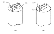
なお、図6の底面の斜視図である図7(a)や(b)に示すように凹部52に排出口52bや排出口52cを設けることにより窒素ガスの流れをコントロールし、半田の分離を確実に行わすことができる。
なお、本実施形態では端子の数量を2本としたが、3本以上の端子数においても実施することが可能である。
(Second Embodiment)
Other examples of the soldering apparatus according to this embodiment will be described with reference to the drawings. FIG. 6 is a diagram showing a main part of the solder processing apparatus of the present invention, and the difference from the first embodiment is that a gas flow is supplied between a plurality of terminals. That is, as shown in FIG. 6A, solder is supplied to the non-wetting recess 51, and gas is blown between the terminal Tp11 and the terminal Tp12. Then, by blowing a nitrogen gas stream onto the central portion of the molten solder as shown in FIG. 6 (b), the land Ld1 (terminal) separated by the resist Re as shown in FIG. 6 (c) by the fluid force thereof. Soldering is performed on Tp11) and land Tp2 (terminal Tp12). Since the recess 52 is non-wetting, it does not adhere to the wall surface of the recess 52, and a certain amount of solder pieces Wh is supplied, so that an appropriate amount of solder is supplied around the terminals Tp11toTp12. At this time, preferably, the separation is surely performed by temporarily increasing the flow velocity of the gas, and even when the distance between the terminals Tp11 and Tp12 is small, soldering can be performed at the same time without forming a bridge in which the terminals are conducted by soldering. It is possible.
As shown in FIGS. 7A and 7B, which are perspective views of the bottom surface of FIG. 6, the discharge port 52b and the discharge port 52c are provided in the recess 52 to control the flow of nitrogen gas and separate the solder. It can be done reliably.
In this embodiment, the number of terminals is set to 2, but it is possible to carry out the procedure even if the number of terminals is 3 or more.

(第3実施形態)
本実施形態にかかる半田処理装置の他の例について図面を参照して説明する。図8は本発明の半田処理装置の要部を示した図であり、第1実施形態との相違は、鏝先5の凹部52を移動させながら半田付けする点にある。図8において鏝先5の凹部52に端子Tpの配列方向に開口部52dを設け、図9(a)に示すように、半田片Whが溶融して凹部52から端子Tp21に流れ込んだときに凹部52と一体の鏝先5を端子の配列方向(矢印で示すような図の左方向)に移動させる。開口部52dの高さは端子Tpの配線基板Bd上の高さより高く設定してあり、移動時に障害になることはない。溶融した半田片Whは端子Tp21や端子Tp22に付着した後図9(b)に示したように溶融した半田片片Whを端子Tp23と端子Tp24に順次供給するものである。端子Tpに付着した半田片WhはランドLdとスルーホールThに流れ、非濡れ性のレジストReで分離され、端子Tp21からTp24まで溶融した半田片Whが供給される。このとき半田片Whが一定量で供給され、かつ凹部52が非濡れ性であることにより、端子Tp21からTp24までブリッジを起こすことなく均等量の半田付けが行われる。鏝先5を移動させるタイミングは、Tp21に溶融半田が供給されたときであり、この時機は半田供給からのタイマによる時間経過や、あるいは端子Tp1への溶融半田の供給を画像センサや温度センサで検出しても良い。
鏝先5の移動手段としては、半田処理装置Aを移動させるロボット(図示せず)を用いても良い。
(Third Embodiment)
Other examples of the soldering apparatus according to this embodiment will be described with reference to the drawings. FIG. 8 is a diagram showing a main part of the soldering apparatus of the present invention, and the difference from the first embodiment is that soldering is performed while moving the recess 52 of the trowel tip 5. In FIG. 8, an opening 52d is provided in the recess 52 of the trowel tip 5 in the arrangement direction of the terminals Tp, and as shown in FIG. 9A, the recess 52 when the solder piece Wh melts and flows into the terminal Tp 21 from the recess 52. The trowel tip 5 integrated with the 52 is moved in the terminal arrangement direction (to the left in the figure as shown by the arrow). The height of the opening 52d is set higher than the height on the wiring board Bd of the terminal Tp, and there is no obstacle when moving. The molten solder piece Wh adheres to the terminal Tp21 and the terminal Tp22, and then the molten solder piece Wh is sequentially supplied to the terminal Tp23 and the terminal Tp24 as shown in FIG. 9B. The solder piece Wh adhering to the terminal Tp flows to the land Ld and the through hole Th, is separated by the non-wetting resist Re, and the solder piece Wh melted from the terminal Tp21 to Tp24 is supplied. At this time, since the solder pieces Wh are supplied in a constant amount and the recess 52 is non-wetting, an equal amount of soldering is performed from the terminals Tp21 to Tp24 without causing a bridge. The timing for moving the tip 5 is when the molten solder is supplied to Tp21, and at this time, the time elapses from the solder supply by the timer or the supply of the molten solder to the terminal Tp1 is performed by an image sensor or a temperature sensor. It may be detected.
As the moving means of the trowel tip 5, a robot (not shown) for moving the solder processing apparatus A may be used.

半田付けされる端子Tpとして、図10(a)に示すような形状の端子Tp31を、図9(b)に示すようにはんだ付けすることも可能である。
また、本発明における半田付け箇所は端子に限らず、他の実装部品にも適用が可能である。
以上、本発明の実施形態について説明したが、本発明はこの内容に限定されるものではない。また本発明の実施形態は、発明の趣旨を逸脱しない限り、種々の改変を加えることが可能である。
As the terminal Tp to be soldered, a terminal Tp31 having a shape as shown in FIG. 10A can be soldered as shown in FIG. 9B.
Further, the soldering location in the present invention is not limited to the terminal, and can be applied to other mounting components.
Although the embodiments of the present invention have been described above, the present invention is not limited to this content. Further, the embodiments of the present invention can be modified in various ways without departing from the spirit of the invention.

5 鏝先
7 ガス供給部
51 半田孔
52 凹部
52a、52b、52c 排出口
52d 開口部
A 半田処理装置
A1 半田供給部
Wh 半田片
Bd 配線基板
Ld ランド
Tp 端子
5 Trowel 7 Gas supply part 51 Solder hole 52 Recession 52a, 52b, 52c Outlet 52d Opening A Solder processing device A1 Solder supply part Wh Solder piece Bd Wiring board Ld Land Tp terminal

Claims (5)

加熱可能である上下に伸びた略筒形状の鏝先と、前記鏝先の端部に設けられた複数の半田付け箇所の一部又は全部を覆う凹部と、前記鏝先内にガスを送出するガス供給部と、前記鏝先内に複数箇所分の半田量を供給する半田供給部とを備え、前記鏝先に半田片を供給して溶融するとともに前記ガスの流体力により前記複数の半田付け箇所に溶融した半田を分配して供給することを特徴とする半田処理装置。 Sending a soldering tip having a substantially cylindrical shape that extends vertically is heatable, and a portion or recess which covers all of the plurality of soldering points provided under end of the soldering tip, the gas into the soldering tip A gas supply unit for supplying solder and a solder supply unit for supplying the amount of solder for a plurality of locations in the tip of the solder are provided, and the solder pieces are supplied into the tip of the solder to melt and the plurality of solder pieces are supplied by the fluid force of the gas. A solder processing device characterized in that molten solder is distributed and supplied to soldering locations. 前記複数の半田付けの箇所の端部から前記ガスを流すことにより溶融半田の分配を促進することを特徴とする請求項1記載の半田処理装置。 The solder processing apparatus according to claim 1, wherein the distribution of molten solder is promoted by flowing the gas from the ends of the plurality of soldering portions. 前記複数の半田付けのそれぞれ箇所の間に前記ガスを流すことにより溶融半田の分を促進することを特徴とする請求項1記載の半田処理装置。 Soldering apparatus according to claim 1, wherein the promoting distributable solder melt by flowing the gas between each portion of the plurality of soldering. 前記半田片の溶融時に、前記鏝先を半田付け箇所の方向に移動させ溶融半田を分配することを特徴とする請求項1に記載の半田処理装置。 The solder processing apparatus according to claim 1 , wherein when the solder piece is melted, the tip of the solder is moved in the direction of the soldering portion to distribute the molten solder. 前記半田片の溶融時に前記ガスの流量を一時的に増加させることを特徴とする請求項1〜4のいずれか1項に記載の半田処理装置。 The solder processing apparatus according to any one of claims 1 to 4, wherein the flow rate of the gas is temporarily increased when the solder pieces are melted.
JP2016241323A 2016-12-13 2016-12-13 Handa processing equipment Active JP6818973B2 (en)

Priority Applications (1)

Application Number Priority Date Filing Date Title
JP2016241323A JP6818973B2 (en) 2016-12-13 2016-12-13 Handa processing equipment

Applications Claiming Priority (1)

Application Number Priority Date Filing Date Title
JP2016241323A JP6818973B2 (en) 2016-12-13 2016-12-13 Handa processing equipment

Publications (3)

Publication Number Publication Date
JP2018094595A JP2018094595A (en) 2018-06-21
JP2018094595A5 JP2018094595A5 (en) 2019-11-28
JP6818973B2 true JP6818973B2 (en) 2021-01-27

Family

ID=62634176

Family Applications (1)

Application Number Title Priority Date Filing Date
JP2016241323A Active JP6818973B2 (en) 2016-12-13 2016-12-13 Handa processing equipment

Country Status (1)

Country Link
JP (1) JP6818973B2 (en)

Families Citing this family (1)

* Cited by examiner, † Cited by third party
Publication number Priority date Publication date Assignee Title
JP2020006405A (en) * 2018-07-09 2020-01-16 株式会社パラット Soldering device and soldering method

Also Published As

Publication number Publication date
JP2018094595A (en) 2018-06-21

Similar Documents

Publication Publication Date Title
US11400534B2 (en) Solder processing device
US6168065B1 (en) Movable selective debridging apparatus for debridging soldered joints on printed circuit boards
JP6366561B2 (en) Soldering apparatus and soldering method
US11207743B2 (en) Solder processing device
JP2016059927A (en) Soldering iron
JP6227992B2 (en) Soldering apparatus and method
JP6512659B2 (en) Solder processing equipment
US20170190002A1 (en) Bonding Method and Bonding Device
JP6818973B2 (en) Handa processing equipment
JP6792858B2 (en) Soldering equipment
JP6929534B2 (en) Twin trowel type soldering device
JP6761930B2 (en) Soldering equipment
JP7382638B2 (en) soldering equipment
JP6821189B2 (en) Twin soldering device
JP3210899U (en) Soldering device
JP2006344871A (en) Method and apparatus of reflow soldering
JP6773322B2 (en) How to judge the dirt condition of the solder hole
JP6813870B2 (en) Soldering equipment
JP6406687B2 (en) Soldering device
JP6766314B2 (en) How to judge the state of the trowel
JP6472127B2 (en) Tip and heat storage tool
JP7103633B2 (en) How to judge the state of the trowel
JP2019179785A (en) Soldering apparatus and soldering method
JP7006925B2 (en) How to judge the state of the trowel
JP3207595U (en) Soldering equipment

Legal Events

Date Code Title Description
A521 Written amendment

Free format text: JAPANESE INTERMEDIATE CODE: A523

Effective date: 20191016

A621 Written request for application examination

Free format text: JAPANESE INTERMEDIATE CODE: A621

Effective date: 20191016

A977 Report on retrieval

Free format text: JAPANESE INTERMEDIATE CODE: A971007

Effective date: 20201007

TRDD Decision of grant or rejection written
A01 Written decision to grant a patent or to grant a registration (utility model)

Free format text: JAPANESE INTERMEDIATE CODE: A01

Effective date: 20201110

A61 First payment of annual fees (during grant procedure)

Free format text: JAPANESE INTERMEDIATE CODE: A61

Effective date: 20201118

R150 Certificate of patent or registration of utility model

Ref document number: 6818973

Country of ref document: JP

Free format text: JAPANESE INTERMEDIATE CODE: R150