JP6791033B2 - Position sensor - Google Patents
Position sensor Download PDFInfo
- Publication number
- JP6791033B2 JP6791033B2 JP2017118777A JP2017118777A JP6791033B2 JP 6791033 B2 JP6791033 B2 JP 6791033B2 JP 2017118777 A JP2017118777 A JP 2017118777A JP 2017118777 A JP2017118777 A JP 2017118777A JP 6791033 B2 JP6791033 B2 JP 6791033B2
- Authority
- JP
- Japan
- Prior art keywords
- detection
- detection target
- signal
- unit
- target
- Prior art date
- Legal status (The legal status is an assumption and is not a legal conclusion. Google has not performed a legal analysis and makes no representation as to the accuracy of the status listed.)
- Active
Links
- 238000001514 detection method Methods 0.000 claims description 269
- 238000012545 processing Methods 0.000 claims description 34
- 230000008859 change Effects 0.000 claims description 10
- 239000000696 magnetic material Substances 0.000 claims description 6
- 230000004048 modification Effects 0.000 description 21
- 238000012986 modification Methods 0.000 description 21
- 239000011347 resin Substances 0.000 description 7
- 229920005989 resin Polymers 0.000 description 7
- 230000007704 transition Effects 0.000 description 7
- 230000000052 comparative effect Effects 0.000 description 4
- 230000005415 magnetization Effects 0.000 description 3
- 230000009955 peripheral mechanism Effects 0.000 description 3
- 230000008901 benefit Effects 0.000 description 2
- 238000004891 communication Methods 0.000 description 2
- 239000000463 material Substances 0.000 description 2
- 238000000034 method Methods 0.000 description 2
- 239000000853 adhesive Substances 0.000 description 1
- 230000001070 adhesive effect Effects 0.000 description 1
- 230000005540 biological transmission Effects 0.000 description 1
- 238000007796 conventional method Methods 0.000 description 1
- 238000010586 diagram Methods 0.000 description 1
- 230000036039 immunity Effects 0.000 description 1
- 238000004519 manufacturing process Methods 0.000 description 1
- 239000007769 metal material Substances 0.000 description 1
- 238000000465 moulding Methods 0.000 description 1
- 230000008569 process Effects 0.000 description 1
- 238000004080 punching Methods 0.000 description 1
Images


Classifications
-
- G—PHYSICS
- G01—MEASURING; TESTING
- G01D—MEASURING NOT SPECIALLY ADAPTED FOR A SPECIFIC VARIABLE; ARRANGEMENTS FOR MEASURING TWO OR MORE VARIABLES NOT COVERED IN A SINGLE OTHER SUBCLASS; TARIFF METERING APPARATUS; MEASURING OR TESTING NOT OTHERWISE PROVIDED FOR
- G01D5/00—Mechanical means for transferring the output of a sensing member; Means for converting the output of a sensing member to another variable where the form or nature of the sensing member does not constrain the means for converting; Transducers not specially adapted for a specific variable
- G01D5/12—Mechanical means for transferring the output of a sensing member; Means for converting the output of a sensing member to another variable where the form or nature of the sensing member does not constrain the means for converting; Transducers not specially adapted for a specific variable using electric or magnetic means
- G01D5/14—Mechanical means for transferring the output of a sensing member; Means for converting the output of a sensing member to another variable where the form or nature of the sensing member does not constrain the means for converting; Transducers not specially adapted for a specific variable using electric or magnetic means influencing the magnitude of a current or voltage
- G01D5/142—Mechanical means for transferring the output of a sensing member; Means for converting the output of a sensing member to another variable where the form or nature of the sensing member does not constrain the means for converting; Transducers not specially adapted for a specific variable using electric or magnetic means influencing the magnitude of a current or voltage using Hall-effect devices
- G01D5/145—Mechanical means for transferring the output of a sensing member; Means for converting the output of a sensing member to another variable where the form or nature of the sensing member does not constrain the means for converting; Transducers not specially adapted for a specific variable using electric or magnetic means influencing the magnitude of a current or voltage using Hall-effect devices influenced by the relative movement between the Hall device and magnetic fields
-
- G—PHYSICS
- G01—MEASURING; TESTING
- G01D—MEASURING NOT SPECIALLY ADAPTED FOR A SPECIFIC VARIABLE; ARRANGEMENTS FOR MEASURING TWO OR MORE VARIABLES NOT COVERED IN A SINGLE OTHER SUBCLASS; TARIFF METERING APPARATUS; MEASURING OR TESTING NOT OTHERWISE PROVIDED FOR
- G01D5/00—Mechanical means for transferring the output of a sensing member; Means for converting the output of a sensing member to another variable where the form or nature of the sensing member does not constrain the means for converting; Transducers not specially adapted for a specific variable
- G01D5/12—Mechanical means for transferring the output of a sensing member; Means for converting the output of a sensing member to another variable where the form or nature of the sensing member does not constrain the means for converting; Transducers not specially adapted for a specific variable using electric or magnetic means
- G01D5/244—Mechanical means for transferring the output of a sensing member; Means for converting the output of a sensing member to another variable where the form or nature of the sensing member does not constrain the means for converting; Transducers not specially adapted for a specific variable using electric or magnetic means influencing characteristics of pulses or pulse trains; generating pulses or pulse trains
- G01D5/249—Mechanical means for transferring the output of a sensing member; Means for converting the output of a sensing member to another variable where the form or nature of the sensing member does not constrain the means for converting; Transducers not specially adapted for a specific variable using electric or magnetic means influencing characteristics of pulses or pulse trains; generating pulses or pulse trains using pulse code
- G01D5/2497—Absolute encoders
-
- G—PHYSICS
- G01—MEASURING; TESTING
- G01B—MEASURING LENGTH, THICKNESS OR SIMILAR LINEAR DIMENSIONS; MEASURING ANGLES; MEASURING AREAS; MEASURING IRREGULARITIES OF SURFACES OR CONTOURS
- G01B7/00—Measuring arrangements characterised by the use of electric or magnetic techniques
-
- G—PHYSICS
- G01—MEASURING; TESTING
- G01D—MEASURING NOT SPECIALLY ADAPTED FOR A SPECIFIC VARIABLE; ARRANGEMENTS FOR MEASURING TWO OR MORE VARIABLES NOT COVERED IN A SINGLE OTHER SUBCLASS; TARIFF METERING APPARATUS; MEASURING OR TESTING NOT OTHERWISE PROVIDED FOR
- G01D5/00—Mechanical means for transferring the output of a sensing member; Means for converting the output of a sensing member to another variable where the form or nature of the sensing member does not constrain the means for converting; Transducers not specially adapted for a specific variable
- G01D5/12—Mechanical means for transferring the output of a sensing member; Means for converting the output of a sensing member to another variable where the form or nature of the sensing member does not constrain the means for converting; Transducers not specially adapted for a specific variable using electric or magnetic means
- G01D5/244—Mechanical means for transferring the output of a sensing member; Means for converting the output of a sensing member to another variable where the form or nature of the sensing member does not constrain the means for converting; Transducers not specially adapted for a specific variable using electric or magnetic means influencing characteristics of pulses or pulse trains; generating pulses or pulse trains
- G01D5/24428—Error prevention
- G01D5/24433—Error prevention by mechanical means
- G01D5/24438—Special design of the sensing element or scale
-
- G—PHYSICS
- G01—MEASURING; TESTING
- G01D—MEASURING NOT SPECIALLY ADAPTED FOR A SPECIFIC VARIABLE; ARRANGEMENTS FOR MEASURING TWO OR MORE VARIABLES NOT COVERED IN A SINGLE OTHER SUBCLASS; TARIFF METERING APPARATUS; MEASURING OR TESTING NOT OTHERWISE PROVIDED FOR
- G01D5/00—Mechanical means for transferring the output of a sensing member; Means for converting the output of a sensing member to another variable where the form or nature of the sensing member does not constrain the means for converting; Transducers not specially adapted for a specific variable
- G01D5/12—Mechanical means for transferring the output of a sensing member; Means for converting the output of a sensing member to another variable where the form or nature of the sensing member does not constrain the means for converting; Transducers not specially adapted for a specific variable using electric or magnetic means
- G01D5/244—Mechanical means for transferring the output of a sensing member; Means for converting the output of a sensing member to another variable where the form or nature of the sensing member does not constrain the means for converting; Transducers not specially adapted for a specific variable using electric or magnetic means influencing characteristics of pulses or pulse trains; generating pulses or pulse trains
- G01D5/245—Mechanical means for transferring the output of a sensing member; Means for converting the output of a sensing member to another variable where the form or nature of the sensing member does not constrain the means for converting; Transducers not specially adapted for a specific variable using electric or magnetic means influencing characteristics of pulses or pulse trains; generating pulses or pulse trains using a variable number of pulses in a train
Description
本発明は、検出対象の位置に対応した信号を出力するポジションセンサに関する。 The present invention relates to a position sensor that outputs a signal corresponding to a position to be detected.
従来より、検出対象の近接をセンシング可能なセンサ部を備えた検出装置が、例えば特許文献1で提案されている。この検出装置では、センサ部が検出対象の近接時に所定のレベルの信号を出力するように構成されている。
Conventionally, for example,
しかしながら、上記従来の技術では、検出対象の移動量が大きくなった場合、検出対象がセンサ部の検出可能範囲を逸脱してしまう可能性がある。言い換えると、センサ部が検出対象を検出できる範囲に限界がある。 However, in the above-mentioned conventional technique, when the movement amount of the detection target becomes large, the detection target may deviate from the detectable range of the sensor unit. In other words, there is a limit to the range in which the sensor unit can detect the detection target.
なお、複数のセンサ部を配置することで検出可能範囲を広げることが考えられる。しかし、複数のセンサ部を設置するスペースが必要である。また、複数のセンサ部を備える構成であるので、検出装置のコストが上がってしまう。 It is conceivable to expand the detectable range by arranging a plurality of sensor units. However, a space for installing a plurality of sensor units is required. Further, since the configuration includes a plurality of sensor units, the cost of the detection device increases.
本発明は上記点に鑑み、検出対象の移動量が大きくなったとしても、1つの検出部によって検出対象の移動を検出することができるポジションセンサを提供することを目的とする。 In view of the above points, an object of the present invention is to provide a position sensor capable of detecting the movement of the detection target by one detection unit even if the movement amount of the detection target becomes large.
上記目的を達成するため、請求項1に記載の発明では、バイアス磁界を発生させる磁石(106、120)と、バイアス磁界が印加される検出素子(124)と、を有し、磁性体で構成された検出対象(200)の移動に伴って検出素子が検出対象から受ける磁界の変化に基づいて、検出対象の移動方向に沿って一方向に並んだ複数の範囲に対応すると共に位相差が異なる複数の検出信号を生成する検出部(122)を備えている。
In order to achieve the above object, the invention according to
また、ポジションセンサは、検出部から複数の検出信号を取得し、複数の検出信号と閾値とを比較し、複数の検出信号と閾値との大小関係の組み合わせに基づいて、複数の範囲のいずれかの範囲の位置として検出対象の位置を特定する信号処理部(123)を備えている。 Further, the position sensor acquires a plurality of detection signals from the detection unit, compares the plurality of detection signals with the threshold value, and based on the combination of the magnitude relationship between the plurality of detection signals and the threshold value, any one of the plurality of ranges. A signal processing unit (123) for specifying a position to be detected as a position in the range of is provided.
そして、検出対象は、複数の範囲に対応する複数の領域部(201〜204)を有している。さらに、複数の領域部は、検出対象のうち検出部が対向する検出面(205)の面内で検出対象の移動方向に階段状に接続されて構成されている。検出部は、検出対象の移動方向における幅が、複数の領域部のうちの最小の領域部の幅よりも短い幅に構成されている。 The detection target has a plurality of region portions (201 to 204) corresponding to a plurality of ranges. Further, the plurality of region portions are configured to be connected in a stepwise manner in the moving direction of the detection target within the plane of the detection surface (205) on which the detection portion faces the detection target. The detection unit is configured such that the width of the detection target in the moving direction is shorter than the width of the smallest region portion among the plurality of region portions.
請求項2に記載の発明では、磁石(207)を含んで構成された検出対象(200)の移動に伴って検出対象から受ける磁界の変化に基づいて、検出対象の移動方向に沿って一方向に並んだ複数の範囲に対応すると共に位相差が異なる複数の検出信号を生成する検出部(122)を備えている点で請求項1に記載の発明と異なる。
In the invention according to
これによると、複数の範囲の端に位置する範囲にも検出対象の位置を示す領域部(201、204)が存在している。このため、検出部は端の領域部の位置を検出する際には端の領域部から受ける磁界の変化に基づいた検出信号を生成することができる。このように、検出対象が検出部の検出可能範囲に対応した構成となっているので、検出対象の移動量が大きくなったとしても、1つの検出部によって検出対象の移動を検出することができる。 According to this, the region portion (201, 204) indicating the position of the detection target also exists in the range located at the end of the plurality of ranges. Therefore, the detection unit can generate a detection signal based on the change in the magnetic field received from the end region portion when detecting the position of the end region portion. In this way, since the detection target has a configuration corresponding to the detectable range of the detection unit, even if the movement amount of the detection target becomes large, the movement of the detection target can be detected by one detection unit. ..
なお、この欄及び特許請求の範囲で記載した各手段の括弧内の符号は、後述する実施形態に記載の具体的手段との対応関係を示すものである。 The reference numerals in parentheses of each means described in this column and the scope of claims indicate the correspondence with the specific means described in the embodiments described later.
以下、本発明の実施形態について図に基づいて説明する。なお、以下の各実施形態相互において、互いに同一もしくは均等である部分には、図中、同一符号を付してある。 Hereinafter, embodiments of the present invention will be described with reference to the drawings. In each of the following embodiments, the same or equal parts are designated by the same reference numerals in the drawings.
(第1実施形態)
以下、本発明の第1実施形態について図を参照して説明する。本実施形態に係るポジションセンサは、検出対象の位置がどの範囲(状態)にあるのかを検出し、その範囲に対応した信号を出力するセンサである。
(First Embodiment)
Hereinafter, the first embodiment of the present invention will be described with reference to the drawings. The position sensor according to the present embodiment is a sensor that detects the range (state) of the position to be detected and outputs a signal corresponding to that range.
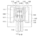
図1に示されるように、ポジションセンサ100は、検出対象として、車両のシフトポジションの動作に連動する可動部品の位置を検出する。具体的には、ポジションセンサ100は、シャフトの位置に応じた信号を検出することで、シャフトの状態を取得する。
As shown in FIG. 1, the
シャフトの状態とは、ユーザによってシフトポジションが操作されたときのシャフトの位置を意味する。例えば、シャフトは、シフトポジションのパーキングに連動して移動する。シフトポジションがパーキングに位置するように操作された場合、シャフトが軸方向に移動する。これにより、シャフトは、パーキングの状態を反映する。ポジションセンサ100はシャフトのうちパーキングに対応した位置を検出する。
The state of the shaft means the position of the shaft when the shift position is operated by the user. For example, the shaft moves in conjunction with parking in the shift position. When the shift position is operated to be in the parking, the shaft moves axially. This causes the shaft to reflect the parking condition. The
一方、シフトポジションがパーキング以外のポジションに位置するように操作された場合、シャフトはパーキング以外の状態を反映する。この場合、ポジションセンサ100は、シャフトのうちパーキングに対応した位置以外の位置を検出する。もちろん、シャフトはパーキング以外のポジションに連動して移動するものでも良い。
On the other hand, when the shift position is operated to be located in a position other than parking, the shaft reflects the state other than parking. In this case, the
シャフトは、例えば全体が磁性体材料によって形成されている。なお、シャフトは、ポジションセンサ100に対向する面が磁性体材料で形成され、他の部分が別の金属材料によって形成されていても良い。
The shaft is entirely made of, for example, a magnetic material. The surface of the shaft facing the
ポジションセンサ100は、PPS等の樹脂材料が樹脂成形されたことによって形成されたケース101を備えている。ケース101は、シャフト側の先端部102、周辺機構に固定されるフランジ部103、ハーネスが接続されるコネクタ部104を有している。先端部102の内部にセンシング部分が設けられている。
The
また、先端部102がシャフトの検出面に対して所定のギャップを持つように、ポジションセンサ100がフランジ部103を介して周辺機構に固定されている。したがって、シャフトがポジションセンサ100に対して移動する。
Further, the
なお、図示しないが、ポジションセンサ100は、シャフトに連動して動作するバルブの位置を検出するように、周辺機構に固定されていても良い。また、シャフトの移動方向は直進や往復に限られず、回転や特定の角度内での往復等でも良い。このように、ポジションセンサ100は、車両のシフトポジションの動作に連動して移動する可動部品の位置や移動、回転等の状態検出に適用できる。
Although not shown, the
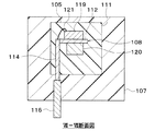
ポジションセンサ100は、磁気抵抗素子を用いた磁気検出方式、または、ホール素子を用いた磁気検出方式を採用することができる。磁気抵抗素子を用いた磁気検出方式の場合、図2に示されるように、ポジションセンサ100は、モールドIC部105、磁石106、及び保持部107を備えている。これらは、ケース101の先端部102に収容されている。モールドIC部105は、中空筒状の磁石106に差し込まれる。磁石106はバイアス磁界を発生させるものであり、有底筒状の保持部107に差し込まれる。
The
図3の平面模式図及び図4の断面模式図に示されるように、モールドIC部105、磁石106、及び保持部107は一体化される。モールドIC部105の主な部分は、磁石106の中空部に位置している。保持部107は、モールドIC部105及び磁石106の位置を固定している。
As shown in the schematic plan view of FIG. 3 and the schematic cross-sectional view of FIG. 4, the
モールドIC部105は、リードフレーム108、処理回路チップ109、センサチップ110、及びモールド樹脂部111を有している。リードフレーム108は、板状のアイランド部112及び複数のリード113〜115を有している。アイランド部112は、平面部が検出対象の移動方向に対して垂直になるように配置されている。
The
複数のリード113〜115は、電源電圧が印加される電源端子113、グランド電圧が印加されるグランド端子114、信号を出力するための出力端子115に対応している。つまり、各リード113〜115は、電源用、グランド用、及び信号用の3本である。各リード113〜115の先端にはターミナル116がそれぞれ接続されている。ターミナル116は、ケース101のコネクタ部104に位置する。また、ターミナル116がハーネスに接続される。
The plurality of
なお、本実施形態では、複数のリード113〜115のうちのグランド用のリード114はアイランド部112に一体化されている。アイランド部112と全てのリード113〜115とが完全に分離されていても良い。
In this embodiment, the
処理回路チップ109及びセンサチップ110は、接着剤等によってアイランド部112に実装されている。処理回路チップ109は、センサチップ110の信号を処理する回路部が構成されている。センサチップ110は、外部から磁界の影響を受けたときに抵抗値が変化する磁気抵抗素子を含んでいる。磁気抵抗素子は、例えばAMR、GMR、TMRである。各リード113〜115と処理回路チップ109とは、ワイヤ117を介して電気的に接続されている。処理回路チップ109とセンサチップ110とは、ワイヤ118を介して電気的に接続されている。
The
モールド樹脂部111は、アイランド部112、各リード113〜115の一部、処理回路チップ109、及びセンサチップ110を封止している。モールド樹脂部111は、磁石106の中空部に固定される形状に成形されている。
The
磁気抵抗素子を用いた磁気検出方式による検出信号について説明する。図5に示されるように、保持部107は、検出対象200に対して所定のギャップを持って配置される。そして、保持部107に対して検出対象200が移動すると、検出対象200の移動方向の中心で検出信号が最大となる。ギャップが大きくなると検出信号の振幅が小さくなり、ギャップが小さくなると検出信号の振幅が大きくなる。このような検出信号に対して閾値を設定することで検出対象200の位置を検出することができる。
A detection signal by a magnetic detection method using a magnetoresistive element will be described. As shown in FIG. 5, the holding
なお、図5では検出対象200の移動と磁気検出素子による検出信号との関係のみを示している。後述するが、検出信号は複数の磁気抵抗素子の出力によって生成する。
Note that FIG. 5 shows only the relationship between the movement of the
ホール素子を用いた磁気検出方式を採用した場合、図6の平面模式図及び図7の断面模式図に示されるように、モールドIC部105は、保持部107に差し込まれて固定される。また、モールドIC部105は、リードフレーム108、ICチップ119、磁石120、及びモールド樹脂部111を有している。
When the magnetic detection method using a Hall element is adopted, the
リードフレーム108のアイランド部112は、平面部が検出対象200の移動方向に対して平行になるように配置されている。一方、各リード113〜115は、検出対象200の移動方向に対して垂直になるように配置されている。グランド用のリード114がアイランド部112に直角に一体化されている。各リード113〜115の先端にはターミナル116がそれぞれ接続されている。
The
ICチップ119は、複数のホール素子と信号処理回路部とが形成されている。つまり、ホール素子を用いた磁気検出方式では1チップ構成になっている。磁石120は、アイランド部112のうちICチップ119とは反対側の面に固定されている。各リード113〜115とICチップ119とは、ワイヤ121を介して電気的に接続されている。モールド樹脂部111は、保持部107の中空部に固定される形状に成形されている。
The
ホール素子を用いた磁気検出方式による検出信号について説明する。図8に示されるように、例えば2つのホール素子(X、Y)が磁石120の上方に配置されている場合、保持部107に対して検出対象200が移動すると、各ホール素子(X、Y)の位置に対応して各検出信号が最大となる。ギャップと検出信号の振幅との関係は磁気抵抗素子を用いた磁気検出方式と同じである。各検出信号に対して閾値を設定することで検出対象200の位置を検出することができる。
A detection signal by a magnetic detection method using a Hall element will be described. As shown in FIG. 8, for example, when two Hall elements (X, Y) are arranged above the
本実施形態では、上記の磁気検出方式のうち磁気抵抗素子を用いた方式を採用する。磁気ベクトルを検出する磁気抵抗素子は、ギャップのずれによる精度誤差をキャンセルできるメリットがある。また、センサチップ110に発生する応力の影響を低減あるいはキャンセルできるメリットがある。よって、高精度な検出が可能である。
In this embodiment, among the above magnetic detection methods, a method using a magnetoresistive element is adopted. The magnetoresistive element that detects the magnetic vector has an advantage that the accuracy error due to the gap shift can be canceled. Further, there is an advantage that the influence of stress generated on the
次に、センサチップ110及び処理回路チップ109に構成された回路構成について説明する。図9に示されるように、ポジションセンサ100とコントローラ300とがハーネス400を介して電気的に接続されている。上述のように、モールドIC部105は3本のリード113〜115を有しているので、ハーネス400は3本の配線によって構成されている。
Next, the circuit configuration configured in the
コントローラ300は、例えばトランスミッションコントローラ(TCU)である。コントローラ300は、電源部301、制御部302、及びグランド部303を備えている。電源部301は、ポジションセンサ100に電源電圧を供給する回路部である。制御部302は、ポジションセンサ100から入力する出力信号に応じて予め決められた制御を行う回路部である。グランド部303はポジションセンサ100のグランド電圧を設定する回路部である。なお、コントローラ300は、電子制御装置(ECU)として構成されていても良い。
The
ポジションセンサ100は、検出部122及び信号処理部123を備えている。検出部122は、磁石106とセンサチップ110に設けられた検出素子124とを有して構成されている。信号処理部123は、処理回路チップ109に設けられている。検出素子124及び信号処理部123は、コントローラ300から供給される電源電圧及びグランド電圧に基づいて動作する。
The
検出部122は、検出対象200の移動に伴って、検出対象200から受ける磁界の変化に基づいて、検出対象200の移動方向に沿った複数の範囲に対応すると共に位相差が異なる複数の検出信号を生成する。検出対象200の移動方向に沿った複数の範囲は、複数の範囲が検出対象200の移動方向に沿って並列に並んでいるのではなく、複数の範囲が検出対象200の移動方向に沿って一方向に直列に並んでいる。
The
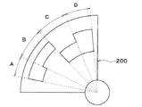
ここで、検出対象200は、図10に示されるように、複数の範囲A〜Dに対応する4つの領域部201〜204を有している。各領域部201〜204は、長方形の板部材によって構成されている。また、各領域部201〜204は、検出対象200のうち検出部122が対向する検出面205の面内で検出対象200の移動方向に階段状に接続されて構成されている。
Here, as shown in FIG. 10, the
「階段状に接続される」とは、一方の領域部201と他方の領域部202とが検出面205の面内において移動方向に対して垂直方向にずれて接続されることである。同様に、一方の領域部202と他方の領域部203が検出面205の面内において移動方向に対して垂直方向にずれて接続される。一方の領域部203と他方の領域部204についても同じである。これにより、各領域部201〜204において移動方向に沿った両端部すなわち2本の長辺部は、階段状の形状を構成している。つまり、領域部201の隣には領域部202が一方向に直列に接続され、領域部202には領域部201が接続された側とは反対側に領域部203が一方向に直列に接続されている。同様に、領域部203には領域部202が接続された側とは反対側に領域部204が一方向に直列に接続されている。
"Connected in a stepped manner" means that one
センサチップ110のうち検出素子124が設けられたチップ面は、検出部122の移動方向に対して垂直な方向に向けられている。そして、位置が固定された検出部122に対して検出対象200が移動方向に移動すると、各領域部201〜204が検出部122に対して検出面205の面内で移動方向に垂直な方向に移動する。このように、検出対象200の移動によって、検出部122と各領域部201〜204との位置関係が変化する。図10では、各領域部201〜204に対してそれぞれ検出部122を配置することにより、各領域部201〜204と検出部122との位置関係を示している。
The chip surface of the
検出対象200は、磁性体材料によって構成された板部材がプレス加工等によって形成される。各領域部201〜204は、移動方向の長さが同一でも良いし、異なっていても良い。また、各領域部201〜204は、検出面205の面内での移動方向に垂直な方向の長さが同一でも良いし、異なっていても良い。なお、検出対象200は、シャフト等の部品に固定される。また、検出対象200は、両端の領域部201、204がシャフトに固定されても良い。
In the
図9の検出素子124は、検出対象200の移動に伴って抵抗値が変化する第1磁気抵抗素子対、第2磁気抵抗素子対、及び第3磁気抵抗素子対の3つの素子対を有している。
The
図示しないが、検出対象200の移動方向において、第2磁気抵抗素子対が第1磁気抵抗素子対と第3磁気抵抗素子対との間に位置するように各々が配置されている。つまり、第2磁気抵抗素子対が第1磁気抵抗素子対と第3磁気抵抗素子対とに挟まれるように配置されている。そして、第2磁気抵抗素子対には磁石106の中心軸に沿ったバイアス磁界が印加される。一方、第1磁気抵抗素子対及び第3磁気抵抗素子対には磁石106の端部を巻き込むバイアス磁界が印加される。
Although not shown, each of them is arranged so that the second magnetoresistive element pair is located between the first magnetoresistive element pair and the third magnetoresistive element pair in the moving direction of the
各磁気抵抗素子対は、電源とグランドとの間に2つの磁気抵抗素子が直列接続されたハーフブリッジ回路として構成されている。各磁気抵抗素子対は、検出対象200の移動に伴って2つの磁気抵抗素子が磁界の影響を受けたときの抵抗値の変化を検出する。また、各磁気抵抗素子対は、当該抵抗値の変化に基づいて、2つの磁気抵抗素子の中点の電圧を波形信号としてそれぞれ出力する。なお、各磁気抵抗素子対が電流源によって駆動される構成では、各磁気抵抗素子対の両端電圧が波形信号となる。
Each magnetoresistive element pair is configured as a half-bridge circuit in which two magnetoresistive elements are connected in series between a power supply and ground. Each magnetoresistive element pair detects a change in resistance value when two magnetoresistive elements are affected by a magnetic field as the
また、検出部122は、各磁気抵抗素子対の他に、図示しない第1〜第4オペアンプを備えている。第1磁気抵抗素子対の中点の中点電位をV1と定義すると共に、第2磁気抵抗素子対の中点の中点電位をV2と定義すると、第1オペアンプは、V1−V2を演算してその結果をR1として出力するように構成された差動増幅器である。また、第3磁気抵抗素子対の中点の中点電位をV3と定義すると、第2オペアンプは、V2−V3を演算してその結果をR2として出力するように構成された差動増幅器である。
Further, the
第3オペアンプは、第1オペアンプからR1(=V1−V2)を入力すると共に第2オペアンプからR2(=V2−V3)を入力し、R2−R1を演算してその結果をS1(=(V2−V3)−(V1−V2))として出力するように構成された差動増幅器である。 The third operational amplifier inputs R1 (= V1-V2) from the first operational amplifier and R2 (= V2-V3) from the second operational amplifier, calculates R2-R1, and outputs the result to S1 (= (V2). It is a differential amplifier configured to output as −V3) − (V1-V2)).
第4オペアンプは、第1磁気抵抗素子対の中点から中点電位V1を入力すると共に、第3磁気抵抗素子対の中点から中点電位V3を入力し、V1−V3を演算してその結果をS2として出力するように構成された差動増幅器である。信号S2は、信号S1に対して位相差を持った波形の信号である。 The fourth operational amplifier inputs the midpoint potential V1 from the midpoint of the first magnetoresistive element pair, inputs the midpoint potential V3 from the midpoint of the third magnetoresistive element pair, calculates V1-V3, and calculates the midpoint potential V3. It is a differential amplifier configured to output the result as S2. The signal S2 is a signal having a waveform having a phase difference with respect to the signal S1.
このように、検出部122は、各磁気抵抗素子対の出力から信号S1(=V1−V3)及び信号S2(=2V2−V1−V3)を生成及び取得するように構成されている。検出部122は、信号S1及び信号S2を検出信号として信号処理部123に出力する。
As described above, the
信号処理部123は、検出部122から各検出信号を取得し、各検出信号と閾値とを比較し、各検出信号と閾値との大小関係の組み合わせに基づいて、検出対象200における複数の範囲のいずれかの範囲の位置として検出対象200の位置を特定する。また、信号処理部123は、検出対象200の位置をコントローラ300に出力する。信号処理部123は、処理部125及び出力回路部126を有している。
The
処理部125は、検出部122から各検出信号を入力し、各検出信号に基づいて検出対象200の位置を特定する。このため、処理部125は、各検出信号に対して共通の閾値を有している。
The
そして、処理部125は、検出信号である信号S1、S2と閾値とを比較する。処理部125は、信号S1、S2が閾値よりも大きい場合をHiと判定し、信号S1、S2が閾値よりも小さい場合をLoと判定する。また、処理部125は、信号S1、S2のHi/Loの組み合わせから、検出部122が検出対象200のどの範囲を検出したのかを判定する。
Then, the
具体的には、図11に示されるように、信号S1がHi、信号S2がLoの場合、検出部122は検出対象200のうち領域部201の範囲を検出したことになる。つまり、処理部125は、検出対象200であるシャフトの位置を特定したことになる。当該範囲の位置を特定した場合のシャフトの状態を「状態A」とする。
Specifically, as shown in FIG. 11, when the signal S1 is Hi and the signal S2 is Lo, the
信号S1がHiの場合、信号S2がHiの場合、検出部122は検出対象200の領域部202のうち範囲を検出したことになる。当該範囲の位置を特定した場合のシャフトの状態を「状態B」とする。
When the signal S1 is Hi and the signal S2 is Hi, the
信号S1がLoの場合、信号S2がHiの場合、検出部122は検出対象200の領域部203のうち範囲を検出したことになる。当該範囲の位置を特定した場合のシャフトの状態を「状態C」とする。
When the signal S1 is Lo and the signal S2 is Hi, the
さらに、信号S1がLo、信号S2がLoの場合、検出部122は検出対象200のうち領域部204の範囲を検出したことになる。当該範囲の位置を特定した場合のシャフトの状態を「状態D」とする。このように、処理部125は、検出対象200の移動方向に沿った複数の範囲のいずれかの範囲の位置として検出対象200の位置を特定する。
Further, when the signal S1 is Lo and the signal S2 is Lo, the
出力回路部126は、処理部125の判定結果に基づいて、上記の状態A〜Dのいずれかを示す位置信号をコントローラ300に出力する回路部である。まず、出力回路部126は、処理部125から検出信号に基づいて判定された状態A〜Dの情報を取得する。また、出力回路部126は、複数の範囲にそれぞれ設定された離散的な値のうち特定した位置の範囲に対応した値の位置信号をコントローラ300に出力する。
The
本実施形態では、離散的な値の位置信号は、電圧値が異なる電圧信号である。例えば、状態AはVH、状態BはVM1、状態CはVM2、状態DはVLというように、各状態A〜Dを示す電圧値が各状態A〜Dで重複しないように、離散的な値に設定される。電圧値の大小関係はVH>VM1>VM2>VLである。離散的な値が各状態A〜Dで重複しなければ良いので、離散的な値は所定の電圧範囲内のいずれかの電圧値として設定されていても良い。所定の電圧範囲は、例えば1V以内というように各状態A〜Dで同じでも良いし、状態Aでは1V以内であるが状態Bでは2V以内であるというように異なっていても良い。 In the present embodiment, the position signals having discrete values are voltage signals having different voltage values. For example, state A is V H , state B is VM1 , state C is VM2 , state D is VL , and so on so that the voltage values indicating each states A to D do not overlap in each state A to D. Set to a discrete value. The magnitude relationship of the voltage values is V H > V M1 > V M2 > VL . Since the discrete values do not overlap in each of the states A to D, the discrete values may be set as any voltage value within a predetermined voltage range. The predetermined voltage range may be the same in each of the states A to D, for example, within 1V, or may be different, such as within 1V in the state A but within 2V in the state B.
図11に示されるように、検出対象200が移動方向に移動した場合、位置信号は階段状の離散的な電圧値となる。また、ノイズによって位置信号の電圧値が瞬間的に上下することで他の状態を示す電圧値に達する場合がある。しかし、コントローラ300の制御部302は所定時間の電圧値を読み取ることでノイズの影響をほとんど無くすことができる。つまり、ポジションセンサ100はノイズ耐性が高い位置信号を出力することができる。以上が、本実施形態に係るポジションセンサ100の構成である。
As shown in FIG. 11, when the
コントローラ300の制御部302は、ポジションセンサ100から位置信号を入力し、所望の制御に利用する。例えば、車両のメータ部のパーキングランプの点消灯制御、シフトポジションがパーキングに入っているか否かに応じて他の制御を許可または不許可する制御、ポジションセンサ100の故障の場合はポジションセンサ100を使用しない制御、故障ランプの点灯制御等である。
The
また、制御部302は、位置信号以外の信号を入力する場合もある。この信号は、ポジションセンサ100の出力としては本来起こりえない信号である。この場合、ポジションセンサ100以外の故障が原因であると考えられる。例えば、ハーネス400等の通信装置の故障等である。したがって、コントローラ300は、通信装置の故障を検知することができる。
Further, the
比較例として、図12に示されるように、ブロック状の検出対象500が移動方向に移動する場合について説明する。この場合、検出部122から検出対象500が離れた位置まで移動すると、検出部122の磁石106が検出対象500に反応しなくなる。このため、信号S1が閾値に収束してしまう。これにより、検出対象500が移動方向のどちらの方向に移動しているのか、判定できなくなってしまう。
As a comparative example, as shown in FIG. 12, a case where the block-shaped
また、検出対象500が移動方向に長さを持っている形状の場合、検出部122が検出対象500の移動方向中心を検出しにくくなってしまう。検出部122は、検出対象500の移動方向の2つのエッジを検出して移動方向中心と判定するため、検出対象500が長くなりエッジ間距離が離れすぎると移動方向中心が分からなくなってしまう。
Further, when the
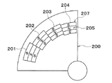
これに対し、本実施形態では、検出対象200の移動方向の範囲内に、検出部122によって検出される部分である各領域部201〜204が設けられている。これにより、図11に示されるように、信号S1、S2は閾値に収束することがなく、閾値に対して明らかにHiまたはLoとなる。もちろん、中央の領域部202と領域部203との境界を検出対象200の中心に設定しておくことで、検出対象200の移動方向中心を検出することも可能である。
On the other hand, in the present embodiment, each
また、図12に示された比較例の問題を起こさないために、検出対象200が移動したとしても、検出対象200−検出部122の相対関係が維持されている。すなわち、複数の範囲の端に位置する範囲にも検出対象200の位置を示す領域部201、204が設けられている。このため、検出部122によって領域部201、204から受ける磁界の変化に基づいた検出信号を生成することができる。
Further, in order not to cause the problem of the comparative example shown in FIG. 12, even if the
したがって、比較例に対して検出部122の検出可能範囲が実質的に広くなっているので、検出対象200の移動量が大きくなったとしても、1つの検出部122によって検出対象200の移動を検出することができる。以上のように、検出対象200を判別したいポジション数で分かれた形状で区分することで、それぞれの区分の判定及び区分に対応した出力をすることができる。
Therefore, since the detectable range of the
変形例として、図13に示されるように、検出対象200を3つの領域部201〜203で構成することもできる。信号処理部123は、信号S3がHi、信号S4がLoの場合を「状態A」とし、信号S4がHiの場合を「状態B」とし、信号S3がLo、信号S4がLoの場合を「状態C」として判定する。この場合、図13に示されるように、3状態を3つの離散的な電圧値に設定すれば良い。
As a modification, as shown in FIG. 13, the
変形例として、図14に示されるように、検出信号として、図13に示された各信号S3、S4とは異なる位相差を持った信号S5、S6を生成することもできる。各信号S5、S6は、各磁気抵抗素子対の出力を用いた演算式を変更することで生成可能である。なお、中央の領域部202が、移動方向において、図13に示された領域部202よりも短く形成されていても良い。
As a modification, as shown in FIG. 14, as a detection signal, signals S5 and S6 having a phase difference different from those of the signals S3 and S4 shown in FIG. 13 can also be generated. The signals S5 and S6 can be generated by changing the calculation formula using the output of each magnetoresistive element pair. The
なお、領域部201〜204の数や、位相差が異なる複数の検出信号を適宜変更することで、検出可能な状態の数を自由に変更できる。したがって、3状態や4状態の検出に限られず、5状態や7状態等の状態数も検出も可能である。
The number of detectable states can be freely changed by appropriately changing the number of
変形例として、図15に示されるように、検出対象200の各領域部201〜204は、板部材の一部が打ち抜かれた空間部として構成されていても良い。この場合、位相差を持った信号S7、S8は、図11に示された信号S1、S2が反転した信号となる。
As a modification, as shown in FIG. 15, each
したがって、信号処理部123は、信号S7がLo、信号S8がHiの場合を「状態A」とし、信号S7がLo、信号S8がLoの場合を「状態B」とし、信号S7がHi、信号S8がLoの場合を「状態C」とし、信号S7がHi、信号S8がHiの場合を「状態D」として判定する。このように、検出部122が検出する位置は、検出対象200の素材部分ではなく、窓状に構成された空間部分として構成されていても良い。
Therefore, the
変形例として、図16に示されるように、領域部201と領域部202との間、及び、領域部202と領域部203との間に遷移部206が設けられていても良い。領域部201〜204の数に関係なく、隣同士の領域間に遷移部206を設けることができる。遷移部206の形状は、直線状やR形状等に限定されない。また、遷移部206は各領域部201〜204が空間部分として構成されている場合にも適用できる。
As a modification, as shown in FIG. 16, a
変形例として、図17に示されるように、センサチップ110のうち検出素子124が設けられたチップ面は、検出部122の移動方向に対して垂直な方向ではなく、傾斜していても良い。なお、図17では、検出対象200に遷移部206が設けられているが、遷移部206は検出対象200に設けられていなくても良い。
As a modification, as shown in FIG. 17, the chip surface of the
変形例として、図18に示されるように、各領域部201〜204は、板部材にブロックが設けられた凹凸形状として構成されていても良い。
As a modification, as shown in FIG. 18, each
変形例として、図19及び図20に示されるように、検出対象200は、扇形状の板部材の一部が打ち抜かれたものでも良い。打ち抜きの形状を考慮することにより、例えば図10に示された階段状の各領域部201〜204を扇形状の周方向に設けることができる。これにより、検出対象200が軸を中心に回転あるいは回動することで各範囲A〜Dの位置の検出が可能になる。
As a modification, as shown in FIGS. 19 and 20, the
変形例として、図21に示されるように、検出対象200はロータ等の回転体として構成されていても良い。この場合、図21の破線部に検出範囲に対応した各領域部201〜204が設けられる。具体的には、図22に示されるように、回転角のθ方向に4つの領域部201〜204が設けられている。これにより、検出部122は検出対象200の回転あるいは回動の状態を検出することができる。
As a modification, as shown in FIG. 21, the
なお、本実施形態の記載と特許請求の範囲の記載との対応関係については、コントローラ300が特許請求の範囲の「外部装置」に対応する。
Regarding the correspondence between the description of the present embodiment and the description of the claims, the
(第2実施形態)
本実施形態では、第1実施形態と異なる部分について説明する。本実施形態では、出力回路部126は、離散的な値の信号として、パルス幅が異なるパルス信号をコントローラ300に出力する。つまり、離散的な値の信号は、PWM方式の信号である。離散的な値は、パルス幅の値、信号の周期、Duty比等である。第1実施形態と同様に、ノイズに対する耐性を向上させることができる。
(Second Embodiment)
In this embodiment, a part different from the first embodiment will be described. In the present embodiment, the
図23に示されるように、例えば、状態Aに対応した信号のパルス幅が最も小さく、状態Dに対応した信号のパルス幅が最も大きく設定されている。状態B、Cに対応した信号のパルス幅は、状態A、Dに対応した信号のパルス幅の間に設定されている。パルス幅は状態Aから状態Dまで段階的に変化していても良いし、ランダムになっていても良い。 As shown in FIG. 23, for example, the pulse width of the signal corresponding to the state A is set to be the smallest, and the pulse width of the signal corresponding to the state D is set to be the largest. The pulse width of the signal corresponding to the states B and C is set between the pulse widths of the signals corresponding to the states A and D. The pulse width may change stepwise from the state A to the state D, or may be random.
(第3実施形態)
本実施形態では、第1、第2実施形態と異なる部分について説明する。本実施形態では、検出対象200の全体あるいは一部を磁石で構成し、ポジションセンサ100に磁石106、120を備えない構成としている。
(Third Embodiment)
In this embodiment, the parts different from the first and second embodiments will be described. In the present embodiment, all or part of the
図24及び図25に示されるように、磁気抵抗素子を用いた磁気検出方式では磁石106が設けられていない。同様に、図26及び図27に示されるように、ホール素子を用いた磁気検出方式では磁石120が設けられていない。したがって、モールドIC部105は保持部107に直接差し込まれて固定される。
As shown in FIGS. 24 and 25, the
図28に示されるように、検出対象200が移動方向に対してセンサチップ110側に磁化方向を持つ磁石207として構成されている。この場合、センサチップ110に設けられた検出部122は、磁極の中心で最大または最小となる信号S9と、各磁極の境界で最大または最小となる信号S10と、を検出信号として信号処理部123に出力する。このように、検出対象200が磁石207で構成されていても、信号S9、S10は、位相差を持った信号となる。
As shown in FIG. 28, the
なお、図28に示された磁石207のN極/S極は逆の配置でも良い。また、検出部122は、信号S9が各磁極の境界で最大または最小となり、信号S10が磁極の中心で最大または最小となるように構成されていても良い。また、1つの領域部201〜204を構成する磁極の極数は3極に限られず、他の極数でも良い。
The north / south poles of the
そして、図29に示されるように、検出対象200の各領域部201〜204は、磁石207のN極が2つのS極に挟まれるように構成されている。これにより、磁石207の磁化方向は紙面垂直方向となる。状態判定は、第1実施形態の図11の場合と同じである。
Then, as shown in FIG. 29, each
変形例として、図30に示されるように、検出対象200は板部材の上に各領域部201〜204を構成する磁石207が貼り付けられたものでも良い。磁化方向は板部材の板面に垂直な方向である。
As a modification, as shown in FIG. 30, the
変形例として、図31に示されるように、検出対象200は磁性体の板部材208の上に設けられたゴム磁石209の一部が磁石207となるように着磁されたものでも良い。磁化方向はゴム磁石209の板面に垂直な方向である。
As a modification, as shown in FIG. 31, the
変形例として、図32に示されるように、検出対象200は扇形状の板部材に磁石207が貼り付けあるいは着磁されたものでも良い。
As a modification, as shown in FIG. 32, the
変形例として、図33に示されるように、検出対象200はロータ等の回転体に磁石207が設けられたのでも良い。この場合、図34に示されるように、回転角のθ方向に4つの領域部201〜204を構成する磁石207が図33の破線部に設けられている。磁石207の構成は図31に示された構成と同じでも良いし、板部材に磁石207が貼り付けられる構成でも良い。
As a modification, as shown in FIG. 33, the
(他の実施形態)
上記各実施形態で示されたポジションセンサ100の構成は一例であり、上記で示した構成に限定されることなく、本発明を実現できる他の構成とすることもできる。例えば、ポジションセンサ100の用途は車両用に限られず、可動部品の位置を検出するものとして産業用ロボットや製造設備等にも広く利用できる。
(Other embodiments)
The configuration of the
また、上記各実施形態では、検出対象200に磁石207が含まれていないが、ポジションセンサ100に磁石106、120が含まれる構成と、検出対象200に磁石207が含まれるが、ポジションセンサ100に磁石106、120が含まれない構成と、が示されているが、これらの組み合わせは一例である。したがって、検出対象200に磁石207が含まれており、ポジションセンサ100に磁石106、120が含まれる構成となっていても良い。この場合、ポジションセンサ100の作動は第1実施形態と同じである。
Further, in each of the above embodiments, the
106、120 磁石
122 検出部
123 信号処理部
124 検出素子
200 検出対象
201〜204 領域部
205 検出面
207 磁石
106, 120
Claims (6)
前記検出部から前記複数の検出信号を取得し、前記複数の検出信号と閾値とを比較し、前記複数の検出信号と前記閾値との大小関係の組み合わせに基づいて、前記複数の範囲のいずれかの範囲の位置として前記検出対象の位置を特定する信号処理部(123)と、
を備え、
前記検出対象は、前記複数の範囲に対応する複数の領域部(201〜204)を有し、
前記複数の領域部は、前記検出対象のうち前記検出部が対向する検出面(205)の面内で前記検出対象の移動方向に階段状に接続されて構成されており、
前記検出部は、前記検出対象の移動方向における幅が、前記複数の領域部のうちの最小の領域部の幅よりも短い幅に構成されているポジションセンサ。 The detection element has a magnet (106, 120) for generating a bias magnetic field and a detection element (124) to which the bias magnetic field is applied, and the detection element is moved as the detection target (200) made of a magnetic material moves. (122) generates a plurality of detection signals corresponding to a plurality of ranges arranged in one direction along the moving direction of the detection target and having different phase differences based on a change in the magnetic field received from the detection target. When,
The plurality of detection signals are acquired from the detection unit, the plurality of detection signals are compared with the threshold value, and any one of the plurality of ranges is based on the combination of the magnitude relationship between the plurality of detection signals and the threshold value. The signal processing unit (123) that specifies the position of the detection target as the position in the range of
With
The detection target has a plurality of region portions (201 to 204) corresponding to the plurality of ranges.
The plurality of region portions are configured to be connected stepwise in the moving direction of the detection target within the plane of the detection surface (205) facing the detection target among the detection targets .
The detection unit is a position sensor having a width in the moving direction of the detection target shorter than the width of the smallest region portion among the plurality of region portions .
前記検出部から前記複数の検出信号を取得し、前記複数の検出信号と閾値とを比較し、前記複数の検出信号と前記閾値との大小関係の組み合わせに基づいて、前記複数の範囲のいずれかの範囲の位置として前記検出対象の位置を特定する信号処理部(123)と、
を備え、
前記検出対象は、前記複数の範囲に対応する複数の領域部(201〜204)を有し、
前記複数の領域部は、前記検出対象のうち前記検出部が対向する検出面(205)の面内で前記検出対象の移動方向に階段状に接続されて構成されており、
前記検出部は、前記検出対象の移動方向における幅が、前記複数の領域部のうちの最小の領域部の幅よりも短い幅に構成されているポジションセンサ。 Based on the change in the magnetic field received from the detection target as the detection target (200) including the magnet (207) moves, a plurality of ranges arranged in one direction along the movement direction of the detection target A detection unit (122) that generates a plurality of detection signals that correspond to each other and have different phase differences.
The plurality of detection signals are acquired from the detection unit, the plurality of detection signals are compared with the threshold value, and any one of the plurality of ranges is based on the combination of the magnitude relationship between the plurality of detection signals and the threshold value. The signal processing unit (123) that specifies the position of the detection target as the position in the range of
With
The detection target has a plurality of region portions (201 to 204) corresponding to the plurality of ranges.
The plurality of region portions are configured to be connected stepwise in the moving direction of the detection target within the plane of the detection surface (205) facing the detection target among the detection targets .
The detection unit is a position sensor having a width in the moving direction of the detection target shorter than the width of the smallest region portion among the plurality of region portions .
Priority Applications (5)
| Application Number | Priority Date | Filing Date | Title |
|---|---|---|---|
| JP2017118777A JP6791033B2 (en) | 2017-06-16 | 2017-06-16 | Position sensor |
| DE112018003012.1T DE112018003012T5 (en) | 2017-06-16 | 2018-05-17 | Position sensor |
| PCT/JP2018/019061 WO2018230244A1 (en) | 2017-06-16 | 2018-05-17 | Position sensor |
| CN201880038378.7A CN110741231B (en) | 2017-06-16 | 2018-05-17 | Position sensor |
| US16/697,806 US11099034B2 (en) | 2017-06-16 | 2019-11-27 | Position sensor |
Applications Claiming Priority (1)
| Application Number | Priority Date | Filing Date | Title |
|---|---|---|---|
| JP2017118777A JP6791033B2 (en) | 2017-06-16 | 2017-06-16 | Position sensor |
Publications (3)
| Publication Number | Publication Date |
|---|---|
| JP2019002835A JP2019002835A (en) | 2019-01-10 |
| JP2019002835A5 JP2019002835A5 (en) | 2019-06-27 |
| JP6791033B2 true JP6791033B2 (en) | 2020-11-25 |
Family
ID=64660757
Family Applications (1)
| Application Number | Title | Priority Date | Filing Date |
|---|---|---|---|
| JP2017118777A Active JP6791033B2 (en) | 2017-06-16 | 2017-06-16 | Position sensor |
Country Status (5)
| Country | Link |
|---|---|
| US (1) | US11099034B2 (en) |
| JP (1) | JP6791033B2 (en) |
| CN (1) | CN110741231B (en) |
| DE (1) | DE112018003012T5 (en) |
| WO (1) | WO2018230244A1 (en) |
Families Citing this family (6)
| Publication number | Priority date | Publication date | Assignee | Title |
|---|---|---|---|---|
| JP2019002469A (en) | 2017-06-14 | 2019-01-10 | 株式会社デンソー | Position sensor |
| JP6743770B2 (en) | 2017-06-16 | 2020-08-19 | 株式会社デンソー | Position sensor |
| JP7167739B2 (en) * | 2019-01-31 | 2022-11-09 | 株式会社デンソー | position sensor |
| JP7279660B2 (en) * | 2020-02-13 | 2023-05-23 | 株式会社デンソー | position sensor |
| JP7422051B2 (en) | 2020-11-02 | 2024-01-25 | 株式会社デンソー | position sensor |
| US11933933B2 (en) | 2021-03-31 | 2024-03-19 | Asahi Kasei Microdevices Corporation | Event detection method, event detection system, and non-transitory computer-readable recording medium |
Family Cites Families (26)
| Publication number | Priority date | Publication date | Assignee | Title |
|---|---|---|---|---|
| JP3319477B2 (en) * | 1993-09-22 | 2002-09-03 | ソニー株式会社 | Phase detection device and rotary drum device |
| US5596272A (en) * | 1995-09-21 | 1997-01-21 | Honeywell Inc. | Magnetic sensor with a beveled permanent magnet |
| JP3358074B2 (en) * | 1995-11-29 | 2002-12-16 | 日本光電工業株式会社 | Angle detector |
| US6038523A (en) * | 1996-05-24 | 2000-03-14 | Seiko Epson Corporation | Position detector, encoder board, position detecting method, timer and electronic device |
| JPH11192853A (en) * | 1998-01-06 | 1999-07-21 | Jidosha Kiki Co Ltd | Transmission control device |
| JP2003259623A (en) * | 2002-03-06 | 2003-09-12 | Denso Corp | Method of transmitting signal |
| JP4135551B2 (en) * | 2002-05-07 | 2008-08-20 | 松下電工株式会社 | Position sensor |
| WO2004099727A1 (en) | 2003-04-22 | 2004-11-18 | Matsushita Electric Works Ltd. | Displacement-detecting device |
| US6992480B2 (en) * | 2003-10-09 | 2006-01-31 | Delphi Technologies, Inc. | Combined incremental and linear magnetic sensor |
| KR100800126B1 (en) * | 2006-08-17 | 2008-01-31 | 에스엘 주식회사 | Electron control transmission lever using hall sensor |
| JP2010160104A (en) * | 2009-01-09 | 2010-07-22 | Aichi Mach Ind Co Ltd | Shift position detector |
| CN101876556B (en) * | 2009-04-30 | 2013-06-12 | 浙江关西电机有限公司 | Position detector and signal processing device thereof |
| JP5056890B2 (en) * | 2010-04-08 | 2012-10-24 | 株式会社デンソー | Stroke amount detection device |
| JP2011235798A (en) * | 2010-05-12 | 2011-11-24 | Bosch Corp | Position detector of change lever, and shift control device of automatic transmission |
| JP2012042405A (en) * | 2010-08-23 | 2012-03-01 | Tokai Rika Co Ltd | Operation position detection device |
| JP5600528B2 (en) * | 2010-09-03 | 2014-10-01 | 株式会社東海理化電機製作所 | Rotation angle detector |
| JP5725007B2 (en) * | 2012-12-27 | 2015-05-27 | 株式会社デンソー | Position detection device |
| US9733317B2 (en) * | 2014-03-10 | 2017-08-15 | Dmg Mori Seiki Co., Ltd. | Position detecting device |
| JP2015178870A (en) | 2014-03-19 | 2015-10-08 | 本田技研工業株式会社 | Gear position detector of manual transmission |
| JP6168010B2 (en) * | 2014-08-06 | 2017-07-26 | トヨタ自動車株式会社 | VEHICLE SHIFT POSITION DETECTING DEVICE AND VEHICLE SHIFT CONTROL DEVICE |
| JP2017062722A (en) * | 2015-09-25 | 2017-03-30 | 株式会社東海理化電機製作所 | Position sensor |
| US10739368B2 (en) * | 2017-05-18 | 2020-08-11 | Infineon Technologies Ag | Incremental speed sensor with redundant sensor elements |
| JP2019002469A (en) | 2017-06-14 | 2019-01-10 | 株式会社デンソー | Position sensor |
| JP6787260B2 (en) | 2017-06-14 | 2020-11-18 | 株式会社デンソー | Position sensor |
| JP6743770B2 (en) | 2017-06-16 | 2020-08-19 | 株式会社デンソー | Position sensor |
| EP3531081B1 (en) * | 2018-02-26 | 2021-04-07 | Melexis Bulgaria Ltd. | Device for position determination of an actuated object |
-
2017
- 2017-06-16 JP JP2017118777A patent/JP6791033B2/en active Active
-
2018
- 2018-05-17 WO PCT/JP2018/019061 patent/WO2018230244A1/en active Application Filing
- 2018-05-17 DE DE112018003012.1T patent/DE112018003012T5/en active Pending
- 2018-05-17 CN CN201880038378.7A patent/CN110741231B/en active Active
-
2019
- 2019-11-27 US US16/697,806 patent/US11099034B2/en active Active
Also Published As
| Publication number | Publication date |
|---|---|
| US11099034B2 (en) | 2021-08-24 |
| US20200096367A1 (en) | 2020-03-26 |
| JP2019002835A (en) | 2019-01-10 |
| CN110741231B (en) | 2022-04-01 |
| WO2018230244A1 (en) | 2018-12-20 |
| CN110741231A (en) | 2020-01-31 |
| DE112018003012T5 (en) | 2020-03-05 |
Similar Documents
| Publication | Publication Date | Title |
|---|---|---|
| JP6791033B2 (en) | Position sensor | |
| KR20170078736A (en) | Magnetic field sensor for sensing a movement of a ferromagnetic target object | |
| US20200072593A1 (en) | Position sensor | |
| KR20170074992A (en) | Magnetic field sensor for sensing a movement of a target object | |
| WO2018230087A1 (en) | Position sensor | |
| WO2018230243A1 (en) | Position sensor | |
| US10739164B2 (en) | Circuit for detecting motion of an object | |
| WO2017094828A1 (en) | Position detection device | |
| US20180023979A1 (en) | Displacement detection device | |
| JP7167739B2 (en) | position sensor | |
| US9678168B2 (en) | Sensor system including multiple comparators | |
| CN111656208B (en) | Magnetic sensor | |
| WO2019167449A1 (en) | Linear position sensor | |
| JP6127271B2 (en) | Giant magnetoresistive element | |
| JP2005257642A (en) | Magnetic detection circuit and encoder | |
| JP5938973B2 (en) | Magnetic sensor | |
| JPH02189484A (en) | Magnetic sensor | |
| JP2016115240A (en) | Multiplication circuit and power sensor including the same | |
| WO2021140724A1 (en) | Position detection device | |
| JP2019128192A (en) | Position detector | |
| JP2018105621A (en) | Magnetic sensor device | |
| WO2016111266A1 (en) | Position detecting device | |
| JP7279660B2 (en) | position sensor | |
| JP5529064B2 (en) | Non-contact switch and magnetic sensor | |
| JP2019105452A (en) | Displacement detection device |
Legal Events
| Date | Code | Title | Description |
|---|---|---|---|
| A521 | Request for written amendment filed |
Free format text: JAPANESE INTERMEDIATE CODE: A523 Effective date: 20190520 |
|
| A621 | Written request for application examination |
Free format text: JAPANESE INTERMEDIATE CODE: A621 Effective date: 20190711 |
|
| A131 | Notification of reasons for refusal |
Free format text: JAPANESE INTERMEDIATE CODE: A131 Effective date: 20200421 |
|
| TRDD | Decision of grant or rejection written | ||
| A01 | Written decision to grant a patent or to grant a registration (utility model) |
Free format text: JAPANESE INTERMEDIATE CODE: A01 Effective date: 20201006 |
|
| A61 | First payment of annual fees (during grant procedure) |
Free format text: JAPANESE INTERMEDIATE CODE: A61 Effective date: 20201019 |
|
| R151 | Written notification of patent or utility model registration |
Ref document number: 6791033 Country of ref document: JP Free format text: JAPANESE INTERMEDIATE CODE: R151 |
|
| R250 | Receipt of annual fees |
Free format text: JAPANESE INTERMEDIATE CODE: R250 |