JP6756356B2 - Transparent heating element, heating element with cover, sensor device, moving body - Google Patents
Transparent heating element, heating element with cover, sensor device, moving body Download PDFInfo
- Publication number
- JP6756356B2 JP6756356B2 JP2018220599A JP2018220599A JP6756356B2 JP 6756356 B2 JP6756356 B2 JP 6756356B2 JP 2018220599 A JP2018220599 A JP 2018220599A JP 2018220599 A JP2018220599 A JP 2018220599A JP 6756356 B2 JP6756356 B2 JP 6756356B2
- Authority
- JP
- Japan
- Prior art keywords
- heating element
- conductor
- connecting conductor
- linear
- bus bar
- Prior art date
- Legal status (The legal status is an assumption and is not a legal conclusion. Google has not performed a legal analysis and makes no representation as to the accuracy of the status listed.)
- Active
Links
Images


Classifications
-
- H—ELECTRICITY
- H05—ELECTRIC TECHNIQUES NOT OTHERWISE PROVIDED FOR
- H05B—ELECTRIC HEATING; ELECTRIC LIGHT SOURCES NOT OTHERWISE PROVIDED FOR; CIRCUIT ARRANGEMENTS FOR ELECTRIC LIGHT SOURCES, IN GENERAL
- H05B3/00—Ohmic-resistance heating
- H05B3/84—Heating arrangements specially adapted for transparent or reflecting areas, e.g. for demisting or de-icing windows, mirrors or vehicle windshields
- H05B3/86—Heating arrangements specially adapted for transparent or reflecting areas, e.g. for demisting or de-icing windows, mirrors or vehicle windshields the heating conductors being embedded in the transparent or reflecting material
-
- H—ELECTRICITY
- H05—ELECTRIC TECHNIQUES NOT OTHERWISE PROVIDED FOR
- H05B—ELECTRIC HEATING; ELECTRIC LIGHT SOURCES NOT OTHERWISE PROVIDED FOR; CIRCUIT ARRANGEMENTS FOR ELECTRIC LIGHT SOURCES, IN GENERAL
- H05B3/00—Ohmic-resistance heating
- H05B3/84—Heating arrangements specially adapted for transparent or reflecting areas, e.g. for demisting or de-icing windows, mirrors or vehicle windshields
-
- G—PHYSICS
- G01—MEASURING; TESTING
- G01S—RADIO DIRECTION-FINDING; RADIO NAVIGATION; DETERMINING DISTANCE OR VELOCITY BY USE OF RADIO WAVES; LOCATING OR PRESENCE-DETECTING BY USE OF THE REFLECTION OR RERADIATION OF RADIO WAVES; ANALOGOUS ARRANGEMENTS USING OTHER WAVES
- G01S7/00—Details of systems according to groups G01S13/00, G01S15/00, G01S17/00
- G01S7/02—Details of systems according to groups G01S13/00, G01S15/00, G01S17/00 of systems according to group G01S13/00
- G01S7/40—Means for monitoring or calibrating
- G01S7/4004—Means for monitoring or calibrating of parts of a radar system
- G01S7/4039—Means for monitoring or calibrating of parts of a radar system of sensor or antenna obstruction, e.g. dirt- or ice-coating
- G01S7/4043—Means for monitoring or calibrating of parts of a radar system of sensor or antenna obstruction, e.g. dirt- or ice-coating including means to prevent or remove the obstruction
- G01S7/4047—Heated dielectric lens, e.g. by heated wire
-
- H—ELECTRICITY
- H01—ELECTRIC ELEMENTS
- H01Q—ANTENNAS, i.e. RADIO AERIALS
- H01Q1/00—Details of, or arrangements associated with, antennas
- H01Q1/02—Arrangements for de-icing; Arrangements for drying-out ; Arrangements for cooling; Arrangements for preventing corrosion
-
- H—ELECTRICITY
- H05—ELECTRIC TECHNIQUES NOT OTHERWISE PROVIDED FOR
- H05B—ELECTRIC HEATING; ELECTRIC LIGHT SOURCES NOT OTHERWISE PROVIDED FOR; CIRCUIT ARRANGEMENTS FOR ELECTRIC LIGHT SOURCES, IN GENERAL
- H05B3/00—Ohmic-resistance heating
- H05B3/10—Heater elements characterised by the composition or nature of the materials or by the arrangement of the conductor
-
- G—PHYSICS
- G01—MEASURING; TESTING
- G01S—RADIO DIRECTION-FINDING; RADIO NAVIGATION; DETERMINING DISTANCE OR VELOCITY BY USE OF RADIO WAVES; LOCATING OR PRESENCE-DETECTING BY USE OF THE REFLECTION OR RERADIATION OF RADIO WAVES; ANALOGOUS ARRANGEMENTS USING OTHER WAVES
- G01S13/00—Systems using the reflection or reradiation of radio waves, e.g. radar systems; Analogous systems using reflection or reradiation of waves whose nature or wavelength is irrelevant or unspecified
- G01S13/88—Radar or analogous systems specially adapted for specific applications
- G01S13/93—Radar or analogous systems specially adapted for specific applications for anti-collision purposes
- G01S13/931—Radar or analogous systems specially adapted for specific applications for anti-collision purposes of land vehicles
- G01S2013/9327—Sensor installation details
- G01S2013/93271—Sensor installation details in the front of the vehicles
-
- H—ELECTRICITY
- H05—ELECTRIC TECHNIQUES NOT OTHERWISE PROVIDED FOR
- H05B—ELECTRIC HEATING; ELECTRIC LIGHT SOURCES NOT OTHERWISE PROVIDED FOR; CIRCUIT ARRANGEMENTS FOR ELECTRIC LIGHT SOURCES, IN GENERAL
- H05B2203/00—Aspects relating to Ohmic resistive heating covered by group H05B3/00
- H05B2203/002—Heaters using a particular layout for the resistive material or resistive elements
- H05B2203/005—Heaters using a particular layout for the resistive material or resistive elements using multiple resistive elements or resistive zones isolated from each other
-
- H—ELECTRICITY
- H05—ELECTRIC TECHNIQUES NOT OTHERWISE PROVIDED FOR
- H05B—ELECTRIC HEATING; ELECTRIC LIGHT SOURCES NOT OTHERWISE PROVIDED FOR; CIRCUIT ARRANGEMENTS FOR ELECTRIC LIGHT SOURCES, IN GENERAL
- H05B2203/00—Aspects relating to Ohmic resistive heating covered by group H05B3/00
- H05B2203/009—Heaters using conductive material in contact with opposing surfaces of the resistive element or resistive layer
- H05B2203/01—Heaters comprising a particular structure with multiple layers
-
- H—ELECTRICITY
- H05—ELECTRIC TECHNIQUES NOT OTHERWISE PROVIDED FOR
- H05B—ELECTRIC HEATING; ELECTRIC LIGHT SOURCES NOT OTHERWISE PROVIDED FOR; CIRCUIT ARRANGEMENTS FOR ELECTRIC LIGHT SOURCES, IN GENERAL
- H05B2203/00—Aspects relating to Ohmic resistive heating covered by group H05B3/00
- H05B2203/011—Heaters using laterally extending conductive material as connecting means
-
- H—ELECTRICITY
- H05—ELECTRIC TECHNIQUES NOT OTHERWISE PROVIDED FOR
- H05B—ELECTRIC HEATING; ELECTRIC LIGHT SOURCES NOT OTHERWISE PROVIDED FOR; CIRCUIT ARRANGEMENTS FOR ELECTRIC LIGHT SOURCES, IN GENERAL
- H05B2203/00—Aspects relating to Ohmic resistive heating covered by group H05B3/00
- H05B2203/013—Heaters using resistive films or coatings
-
- H—ELECTRICITY
- H05—ELECTRIC TECHNIQUES NOT OTHERWISE PROVIDED FOR
- H05B—ELECTRIC HEATING; ELECTRIC LIGHT SOURCES NOT OTHERWISE PROVIDED FOR; CIRCUIT ARRANGEMENTS FOR ELECTRIC LIGHT SOURCES, IN GENERAL
- H05B2203/00—Aspects relating to Ohmic resistive heating covered by group H05B3/00
- H05B2203/014—Heaters using resistive wires or cables not provided for in H05B3/54
Description
本発明は、センサに対面して配置される透明発熱体、透明発熱体を備えるカバー付き発熱体、カバー付き発熱体を備えるセンサ装置、および、透明発熱体、カバー付き発熱体またはセンサ装置を備える移動体に関する。 The present invention includes a transparent heating element arranged facing the sensor, a covered heating element having a transparent heating element, a sensor device including a covered heating element, and a transparent heating element, a covered heating element or a sensor device. Regarding moving elements.
屋外に設置されるカメラや移動体に搭載されるレーダ等、外部の様子を観測するためのセンサが広く用いられている。このようなセンサは、外部からの光や電波を受信することで機能する。例えば、自動車等に搭載された衝突予防システムは、外部に向けて電波(ミリ波)を発信し、外部で反射した電波をレーダで受信することで、外部の障害物と自動車との衝突を予測し、自動的に衝突を防止するための安全対策を行うことができる。 Sensors for observing external conditions, such as cameras installed outdoors and radars mounted on moving objects, are widely used. Such a sensor functions by receiving light or radio waves from the outside. For example, a collision prevention system installed in an automobile or the like transmits radio waves (millimeter waves) to the outside and receives the radio waves reflected from the outside by a radar to predict a collision between an external obstacle and the automobile. However, safety measures can be taken to automatically prevent collisions.
このようなセンサには、センサを保護するためのカバーや意匠性を向上させるための意匠部等の部材がセンサに対面して配置されることがある。センサの機能を妨げないために、このような部材は、光や電波を透過することができるよう構成される。例えば、衝突予防システムには、特許文献1に示されているように、意匠性を有する自動車のエンブレムが衝突予防システムに対面して配置される。このエンブレムによって、衝突予防システムが外部から視認されなくなり、自動車の意匠性を向上させることができる。また、このようなエンブレムは、電波が透過することができるよう構成されている。
In such a sensor, a member such as a cover for protecting the sensor and a design portion for improving the design may be arranged facing the sensor. In order not to interfere with the function of the sensor, such a member is configured to be capable of transmitting light and radio waves. For example, in the collision prevention system, as shown in
しかしながら、センサに対面して配置される部材の表面に多量の雪や水滴が付着すると、光や電波が雪や水滴に阻まれて透過することができず、センサが光や電波を受信できなくなり得る。そこで、雪や水滴を除去するために、センサに対面して発熱体を配置することが考えられた。発熱体は、発熱用導電体に通電されることで、抵抗加熱により発熱する。発熱体の熱がセンサに対面して配置される部材の表面に伝わることで、雪や水滴を除去することができる。 However, if a large amount of snow or water droplets adheres to the surface of the member arranged facing the sensor, the light or radio waves cannot be transmitted because they are blocked by the snow or water droplets, and the sensor cannot receive the light or radio waves. obtain. Therefore, in order to remove snow and water droplets, it was considered to place a heating element facing the sensor. The heating element generates heat by resistance heating when the heating conductor is energized. Snow and water droplets can be removed by transferring the heat of the heating element to the surface of the member arranged facing the sensor.
ところが、センサに対面して配置される部材がカメラのカバーや自動車のエンブレム等のような小型の部材である場合、センサに対面して配置される発熱体もまた小さくなる。したがって、狭い領域に発熱用導電体を配置することになるため、発熱用導電体を適切な抵抗値で配置することが困難であり、発熱体を適切に発熱させることが困難であった。このため、発熱量が不足してセンサに対面して配置される部材の表面に付着した雪や水滴を除去できないことがあった。 However, when the member arranged facing the sensor is a small member such as a camera cover or an automobile emblem, the heating element arranged facing the sensor is also small. Therefore, since the heat generating conductor is arranged in a narrow region, it is difficult to arrange the heat generating conductor with an appropriate resistance value, and it is difficult to appropriately generate heat of the heating element. For this reason, the amount of heat generated may be insufficient to remove snow and water droplets adhering to the surface of the member arranged facing the sensor.
本発明はこのような点を考慮してなされたものであり、センサに対面して配置される透明発熱体において、発熱用導電体の抵抗値を適切に調節することを目的とする。 The present invention has been made in consideration of such a point, and an object of the present invention is to appropriately adjust the resistance value of the heating conductor in a transparent heating element arranged facing the sensor.
本発明の透明発熱体は、
センサに対面して配置される透明発熱体であって、
第1方向に離間して配置された一対のバスバーと、
前記一対のバスバーを連結する複数の連結導電体を有し、
前記連結導電体は、前記第1方向に非平行な第2方向に配列され、
前記連結導電体は、前記第1方向へ少なくとも2回折り返されている。
The transparent heating element of the present invention
A transparent heating element placed facing the sensor.
A pair of busbars spaced apart in the first direction,
It has a plurality of connecting conductors that connect the pair of bus bars.
The connecting conductors are arranged in a second direction, which is non-parallel to the first direction.
The connecting conductor is folded back at least twice in the first direction.
本発明の透明発熱体において、各連結導電体は、前記第1方向に延び且つ前記第2方向に配列された少なくとも3つの線状部と、2つの前記線状部を接続する接続部と、を含んでもよい。 In the transparent heating element of the present invention, each connecting conductor has at least three linear portions extending in the first direction and arranged in the second direction, and a connecting portion connecting the two linear portions. May include.
本発明の透明発熱体は、
センサに対面して配置される透明発熱体であって、
第1方向に離間して配置された一対のバスバーと、
前記一対のバスバーを連結する発熱用導電体と、を備え、
前記発熱用導電体は、各々が前記一対のバスバーを連結する複数の連結導電体を有し、
前記連結導電体は、前記第1方向に非平行な第2方向に配列され、
ある前記接続部が接続する前記線状部の一方は、当該接続部に接続する部分より前記第1方向の一側において直接的に、または他の接続部および線状部を介して間接的に、前記バスバーの一方と接続し、当該接続部が接続する前記線状部の他方は、当該接続部に接続する部分より前記第1方向の一側において直接的に、または他の接続部および線状部を介して間接的に、前記バスバーの他方と接続している。
The transparent heating element of the present invention
A transparent heating element placed facing the sensor.
A pair of busbars spaced apart in the first direction,
A heat-generating conductor for connecting the pair of bus bars is provided.
Each of the heat generating conductors has a plurality of connecting conductors that connect the pair of bus bars.
The connecting conductors are arranged in a second direction, which is non-parallel to the first direction.
One of the linear portions to which the connecting portion is connected is directly on one side of the first direction from the portion connecting to the connecting portion, or indirectly via the other connecting portion and the linear portion. , The other of the linear portions connected to one of the busbars and connected to the connecting portion is directly on one side of the first direction from the portion connecting to the connecting portion, or the other connecting portion and wire. It is indirectly connected to the other side of the bus bar via the shape portion.
本発明の透明発熱体において、前記接続部は、前記第2方向において隣り合う2つの前記線状部を接続してもよい。 In the transparent heating element of the present invention, the connecting portion may connect two adjacent linear portions in the second direction.
本発明の透明発熱体において、各連結導電体において、前記第2方向の最も一側に配置された前記線状部が、前記第1方向の一側に配置された前記バスバーに接続し、前記第2方向の最も他側に配置された前記線状部が、前記第1方向の他側に配置された前記バスバーに接続してもよい。 In the transparent heating element of the present invention, in each connecting conductor, the linear portion arranged on the most one side in the second direction is connected to the bus bar arranged on one side in the first direction, and the said The linear portion arranged on the other side in the second direction may be connected to the bus bar arranged on the other side in the first direction.
本発明の透明発熱体において、
前記複数の連結導電体は、第1群の連結導電体と、第2群の連結導電体と、を含み、
前記第1群の連結導電体において、前記第2方向の最も一側に配置された前記線状部が、前記第1方向の一側に配置された前記バスバーに接続し、前記第2方向の最も他側に配置された前記線状部が、前記第1方向の他側に配置された前記バスバーに接続し、
前記第2群の連結導電体において、前記第2方向の最も一側に配置された前記線状部が、前記第1方向の他側に配置された前記バスバーに接続し、前記第2方向の最も他側に配置された前記線状部が、前記第1方向の一側に配置された前記バスバーに接続してもよい。
In the transparent heating element of the present invention
The plurality of connecting conductors include a first group of connecting conductors and a second group of connecting conductors.
In the first group of connecting conductors, the linear portion arranged on the most one side in the second direction is connected to the bus bar arranged on one side in the first direction, and is connected to the bus bar in the second direction. The linear portion arranged on the other side is connected to the bus bar arranged on the other side in the first direction.
In the second group of connecting conductors, the linear portion arranged on the most one side in the second direction is connected to the bus bar arranged on the other side in the first direction, and is connected to the bus bar in the second direction. The linear portion arranged on the other side may be connected to the bus bar arranged on one side in the first direction.
本発明の透明発熱体において、隣り合う前記第1群の連結導電体と前記第2群の連結導電体とを接続する接続導電体がさらに設けられていてもよい。 In the transparent heating element of the present invention, a connecting conductor for connecting the adjacent first group of connecting conductors and the second group of connecting conductors may be further provided.
本発明の透明発熱体において、前記第1群の連結導電体と前記第2群の連結導電体とは、前記第2方向において交互に配置されていてもよい。 In the transparent heating element of the present invention, the connecting conductors of the first group and the connecting conductors of the second group may be alternately arranged in the second direction.
本発明の透明発熱体において、前記接続導電体が接続する一方の前記連結導電体の、前記第1方向の一側のバスバーに接続している部分から前記接続導電体に接続している部分までの抵抗値に対する、前記接続導電体に接続している部分から前記第1方向の他側のバスバーに接続している部分までの抵抗値の比は、前記接続導電体が接続する他方の前記連結導電体の、前記第1方向の一側のバスバーに接続している部分から前記接続導電体に接続している部分までの抵抗値に対する、前記接続導電体に接続している部分から前記第1方向の他側のバスバーに接続している部分までの抵抗値の比と、等しくなっていてもよい。 In the transparent heating element of the present invention, from the portion of the connecting conductor to which the connecting conductor is connected to the bus bar on one side in the first direction to the portion connected to the connecting conductor. The ratio of the resistance value from the portion connected to the connecting conductor to the portion connected to the bus bar on the other side in the first direction is the ratio of the resistance value to the resistance value of the other connected conductor to which the connecting conductor is connected. The first portion of the conductor connected to the connecting conductor with respect to the resistance value from the portion connected to the bus bar on one side of the first direction to the portion connected to the connecting conductor. It may be equal to the ratio of the resistance values to the part connected to the bus bar on the other side of the direction.
本発明の透明発熱体において、前記接続導電体で接続された2つの前記連結導電体は、当該接続導電体を通るある直線に対して、線対称になっていてもよい。 In the transparent heating element of the present invention, the two connecting conductors connected by the connecting conductor may be line-symmetrical with respect to a straight line passing through the connecting conductor.
本発明の透明発熱体において、前記バスバーは、複数の開口部を有するメッシュ状のパターンで形成されていてもよい。 In the transparent heating element of the present invention, the bus bar may be formed in a mesh-like pattern having a plurality of openings.
本発明の透明発熱体において、
前記バスバーは、複数の開口部を有するメッシュ状のパターンで形成され、
前記開口部の前記第2方向における長さは、前記第2方向において隣り合う2つの前記線状部の距離と同一であってもよい。
In the transparent heating element of the present invention
The bus bar is formed in a mesh-like pattern having a plurality of openings.
The length of the opening in the second direction may be the same as the distance between two adjacent linear portions in the second direction.
本発明の透明発熱体において、
前記メッシュ状のパターンは、複数の線状導電体を配置することで形成され、
前記線状導電体の幅は、前記連結導電体の幅より大きくなっていてもよい。
In the transparent heating element of the present invention
The mesh-like pattern is formed by arranging a plurality of linear conductors.
The width of the linear conductor may be larger than the width of the connecting conductor.
本発明の透明発熱体において、
前記メッシュ状のパターンは、複数の線状導電体を配置することで形成され、
前記線状導電体の断面積は、前記連結導電体の断面積より大きくなっていてもよい。
In the transparent heating element of the present invention
The mesh-like pattern is formed by arranging a plurality of linear conductors.
The cross section of the linear conductor may be larger than the cross section of the connecting conductor.
本発明の透明発熱体において、
前記メッシュ状のパターンは、複数の線状導電体を配置することで形成され、
前記線状導電体は、曲線、又は、直線及び曲線の組み合わせの形状を有してもよい。
In the transparent heating element of the present invention
The mesh-like pattern is formed by arranging a plurality of linear conductors.
The linear conductor may have a curved line or a combination of straight lines and curved lines.
本発明の透明発熱体において、
前記メッシュ状のパターンは、複数の線状導電体を配置することで形成され、
前記線状導電体は、円弧を組み合わせた形状を有してもよい。
In the transparent heating element of the present invention
The mesh-like pattern is formed by arranging a plurality of linear conductors.
The linear conductor may have a shape in which arcs are combined.
本発明の透明発熱体において、1つの前記連結導電体が第2方向において配置されている領域は、他の1つの連結導電体が第2方向において配置されている領域と、一部分において重なっていてもよい。 In the transparent heating element of the present invention, the region where one of the connecting conductors is arranged in the second direction partially overlaps with the region where the other connecting conductor is arranged in the second direction. May be good.
本発明の透明発熱体において、前記連結導電体は、直線、曲線、又は、直線及び曲線の組み合わせの形状を有してもよい。 In the transparent heating element of the present invention, the connecting conductor may have a straight line, a curved line, or a shape of a combination of a straight line and a curved line.
本発明の透明発熱体において、前記連結導電体は、円弧を組み合わせた形状を有してもよい。 In the transparent heating element of the present invention, the connecting conductor may have a shape in which arcs are combined.
本発明の透明発熱体において、ある1つの前記連結導電体の幅は、当該連結導電体よりも経路長が短い他の1つの前記連結導電体の幅より、広くなっていてもよい。 In the transparent heating element of the present invention, the width of one of the connecting conductors may be wider than the width of the other connecting conductor having a shorter path length than the connecting conductor.
本発明の透明発熱体において、前記連結導電体の幅は、20μm以下であってもよい。 In the transparent heating element of the present invention, the width of the connecting conductor may be 20 μm or less.
本発明の第1のカバー付き発熱体は、
カバーと、
前記カバー上に設けられた上述したいずれかの透明発熱体と、を備え、
前記カバーは、第1領域と、前記第1領域より反射率が低い第2領域と、を含み、
前記透明発熱体の前記一対のバスバーは、前記第2領域に重なる位置にのみ配置され、
前記一対のバスバーは、前記カバーと対面する側とは反対側に暗色層を含む。
The first heating element with a cover of the present invention is
With the cover
With any of the above-mentioned transparent heating elements provided on the cover,
The cover includes a first region and a second region having a lower reflectance than the first region.
The pair of busbars of the transparent heating element are arranged only at positions overlapping the second region.
The pair of busbars include a dark layer on the side opposite to the side facing the cover.
本発明の第2のカバー付き発熱体は、
カバーと、
前記カバー上に設けられた上述したいずれかの透明発熱体と、を備え、
前記カバーは、第1領域と、前記第1領域より反射率が低い第2領域と、を含み、
前記第1領域における前記バスバーの非被覆率は、前記第2領域における前記バスバーの非被覆率より高く、
前記バスバーは、前記カバーと対面する側とは反対側に暗色層を含む。
The second covered heating element of the present invention is
With the cover
With any of the above-mentioned transparent heating elements provided on the cover,
The cover includes a first region and a second region having a lower reflectance than the first region.
The non-coverage ratio of the bus bar in the first region is higher than the non-coverage ratio of the bus bar in the second region.
The bus bar includes a dark layer on the side opposite to the side facing the cover.
本発明の第3のカバー付き発熱体は、
カバーと、
前記カバー上に設けられた上述したいずれかの透明発熱体と、を備え、
前記カバーは、第1領域と、前記第1領域より反射率が低い第2領域と、を含み、
前記第1領域における前記連結導電体の非被覆率は、前記第2領域における前記連結導電体の非被覆率より高く、
前記連結導電体は、前記カバーと対面する側とは反対側に暗色層を含む。
The third covered heating element of the present invention is
With the cover
With any of the above-mentioned transparent heating elements provided on the cover,
The cover includes a first region and a second region having a lower reflectance than the first region.
The non-coating rate of the connecting conductor in the first region is higher than the non-covering rate of the connecting conductor in the second region.
The connecting conductor includes a dark color layer on the side opposite to the side facing the cover.
本発明の第3のカバー付き発熱板において、
前記透明発熱体の前記連結導電体は、前記第2領域に重なる位置にのみ配置されてもよい。
In the third heating plate with a cover of the present invention,
The connecting conductor of the transparent heating element may be arranged only at a position overlapping the second region.
本発明のセンサ装置は、
センサと、
前記センサに対面して配置された上述したいずれかのカバー付き発熱体と、を備え、
前記センサは、前記カバー付き発熱体の前記透明発熱体に対面して配置される。
The sensor device of the present invention
With the sensor
It comprises any of the above-mentioned covered heating elements disposed facing the sensor.
The sensor is arranged to face the transparent heating element of the covered heating element.
本発明の移動体は、上述したいずれかの透明発熱体、上述したいずれかのカバー付き発熱体、または上述したセンサ装置を備える。 The moving element of the present invention comprises any of the above-mentioned transparent heating elements, any of the above-mentioned covered heating elements, or the above-mentioned sensor device.
本発明によれば、センサに対面して配置される透明発熱体において、発熱用導電体の抵抗値を適切に調節することができる。 According to the present invention, the resistance value of the heating conductor can be appropriately adjusted in the transparent heating element arranged facing the sensor.
以下、図面を参照して本発明の一実施の形態について説明する。なお、本件明細書に添付する図面においては、図示と理解のしやすさの便宜上、適宜縮尺および縦横の寸法比等を、実物のそれらから変更し誇張してある。 Hereinafter, an embodiment of the present invention will be described with reference to the drawings. In the drawings attached to the present specification, the scale, aspect ratio, etc. are appropriately changed from those of the actual product and exaggerated for the convenience of illustration and comprehension.
なお、本明細書において、「板」、「シート」、「フィルム」の用語は、呼称の違いのみに基づいて、互いから区別されるものではない。例えば、「導電体付きシート」は板やフィルムと呼ばれ得るような部材をも含む概念であり、したがって、「導電体付きシート」は、「導電体付板」や「導電体付きフィルム」と呼ばれる部材と、呼称の違いのみにおいて区別され得ない。 In addition, in this specification, the terms "board", "sheet", and "film" are not distinguished from each other based only on the difference in designation. For example, "sheet with conductor" is a concept that includes members that can be called a plate or film. Therefore, "sheet with conductor" is referred to as "plate with conductor" or "film with conductor". It cannot be distinguished only by the difference between the called member and the name.
また、「シート面(板面、フィルム面)」とは、対象となるシート状(板状、フィルム状)の部材を全体的かつ大局的に見た場合において対象となるシート状部材(板状部材、フィルム状部材)の平面方向と一致する面のことを指す。 Further, the "sheet surface (plate surface, film surface)" is a target sheet-like member (plate-like) when the target sheet-like (plate-like, film-like) member is viewed as a whole and from a broad perspective. A surface that coincides with the plane direction of a member or film-like member).
また、本明細書において用いる、形状や幾何学的条件ならびにそれらの程度を特定する、例えば、「平行」、「直交」、「同一」等の用語や長さや角度の値等については、厳密な意味に縛られることなく、同様の機能を期待し得る程度の範囲を含めて解釈することとする。 In addition, as used in this specification, the terms such as "parallel", "orthogonal", and "identical" and the values of length and angle, etc., which specify the shape and geometric conditions and their degrees, are strictly defined. Without being bound by the meaning, we will interpret it including the range where similar functions can be expected.
図1〜図12は、本発明による一実施の形態および変形例を説明するための図である。このうち図1は、透明発熱体を備えた自動車を概略的に示す図であり、図2は、透明発熱体をその板面の法線方向から見た図であり、図3は、図2のIII−III線に沿った透明発熱体の断面図である。 1 to 12 are diagrams for explaining one embodiment and modification according to the present invention. Of these, FIG. 1 is a diagram schematically showing an automobile equipped with a transparent heating element, FIG. 2 is a view of the transparent heating element viewed from the normal direction of the plate surface, and FIG. 3 is a view of FIG. It is sectional drawing of the transparent heating element along the line III-III of.
図1に示されているように、移動体1の一例としての自動車は、センサ装置2を備えている。センサ装置2は、センサ8と、センサ8に対面して配置されたカバー付き発熱体3と、を有している。カバー付き発熱体3は、カバー4と、カバー4上に設けられた透明発熱体10と、を有している。このようなカバー4は、センサ8を外部から保護する。また、カバー4には、意匠性が付与されていてもよい。例えば、カバー4は、移動体1に意匠性を付与するエンブレム5であってもよい。すなわち、図示された例において、移動体1の一例としての自動車は、センサ8と、センサ8に対面して配置されたエンブレム5および透明発熱体10と、を有している。センサ8として、衝突予防システムのレーダを例示することができる。図示された例において、透明発熱体10は、エンブレム5上に設けられている。透明発熱体10は、自動車のエンブレム5と同程度の大きさの小型の部材であり、例えば平面視において1辺の長さが50mm以上250mm以下の矩形である、板状部材である。また、自動車はバッテリー等の電源7を有している。
As shown in FIG. 1, an automobile as an example of the moving
エンブレム5は、第1領域5aと、第2領域5bと、を含んでいる。第1領域5aは、エンブレム5における文字や記号等によってロゴマーク等を表示する領域であり、銀色等の光沢のある色となっている。第2領域5bは、エンブレム5におけるロゴマーク等の背景となる領域であり、黒色等の暗色系の色となっている。したがって、第1領域5aの反射率は、第2領域5bの反射率より高くなっている。ただし、この例に限らず、暗色系の色となっている第2領域5bによってロゴマーク等が表示され、光沢のある色となっている第1領域5aがロゴマーク等の背景となっていてもよい。
The emblem 5 includes a
このエンブレム5上に設けられた透明発熱体10をその板面の法線方向から見たものが、図2に示されている。図2には、一例として「A」の形状を含むエンブレム5が示されている。図示された例では、「A」の文字を形成する領域が、光沢のある色となっている第1領域5aであり、「A」の文字を形成する領域以外の領域が、暗色系の色となっている第2領域5bである。また、図2の透明発熱体10のIII−III線に対応する断面図を図3に示す。図3に示されているように、エンブレム5上に設けられる透明発熱体10は、樹脂や接合剤等からなる透明層11と、透明層11に積層された、または透明層11内に埋め込まれた導電体付きシート20と、を有している。なお、図示された例では、透明発熱体10は平板状であるが、湾曲していてもよい。さらに、図2のカバー付き発熱体3のIII−III線に対応する断面図を図3Aに示す。図3Aに示されている例では、エンブレム5は、透明層11を介して、透明発熱体10と接合している。また、図3及び図3Aに示された例の透明発熱体10において、導電体付きシート20の後述する発熱用導電体30が設けられた側の透明層11と、後述する基材21が設けられた側の透明層11とは、同一の材料で同一に構成されていてもよいし、或いは、材料および構成の少なくとも一方において互いに異なるようにしてもよい。
A view of the
導電体付きシート20は、基材21と、基材21の面上に設けられた発熱用導電体30と、発熱用導電体30に通電するための一対のバスバー25と、を有する。図2に示すように、バスバー25は、エンブレム5の第2領域5bに重なる位置にのみ配置されていることが好ましい。また、発熱用導電体30は、エンブレム5の第1領域5aに重なる位置より、第2領域5bに重なる位置により高い密度で配置されていることが好ましく、第2領域5bに重なる位置にのみ配置されていることがより好ましい。さらに、図3Aに示す例では、発熱用導電体30の基材21の側とは反対側が、エンブレム5と対面している。言い換えると、発熱用導電体30のエンブレム5と対面する側とは反対側、すなわち基材21の側が、外部から観察され得る。
The
また、図2によく示されているように、透明発熱体10は、発熱用導電体30に通電するための配線部15を有している。図示された例では、バッテリー等の電源7によって、配線部15から導電体付きシート20のバスバー25を介して発熱用導電体30に通電し、発熱用導電体30を抵抗加熱により発熱させる。発熱用導電体30で発生した熱は透明発熱体10の表面に伝わり、透明発熱体10の表面が温められる。これにより、透明発熱体10の表面に付着した雪や水滴を取り除くことができる。したがって、透明発熱体10により、センサ8に対面する位置から電波を妨げる雪や水滴を除去して、センサ8を正常に機能させることができる。
Further, as is well shown in FIG. 2, the
なお、透明発熱体10の「透明」とは、当該透明発熱体を介して当該透明発熱体の一方の側から他方の側を透視し得る程度の透明性を有していることを意味しており、例えば、30%以上、より好ましくは70%以上の可視光透過率を有していることを意味する。可視光透過率は、分光光度計((株)島津製作所製「UV−3100PC」、JIS K 0115準拠品)を用いて測定波長380nm〜780nmの範囲内で測定したときの、各波長における透過率の平均値として特定される。
The term "transparent" of the
次に、導電体付きシート20について説明する。導電体付きシート20は、透明発熱体10と略同一の平面寸法を有して、透明発熱体10の全体にわたって配置されている。以下、導電体付きシート20の各構成要素について説明する。
Next, the
基材21は、発熱用導電体30を支持する部材である。基材21は、透明な電気絶縁性のフィルムである。基材21としては、可視光を透過し、発熱用導電体30を適切に支持し得るものであればいかなる材料でもよいが、例えば、ポリエチレンテレフタレート、ポリエチレンナフタレート、ポリカーボネート、ポリスチレン、環状ポリオレフィン等を挙げることができる。また、基材21は、光透過性や、発熱用導電体30の適切な支持性、耐久性及び熱伝導性等を考慮すると、0.03mm以上0.20mm以下の厚みを有していることが好ましい。
The
一対のバスバー25は、第1方向d1に離間して配置され、それぞれが対応する配線部15と電気的に接続されている。一対のバスバー25間には、配線部15と接続された電源7の電圧が印加されるようになる。また、図2等に示された例では、バスバー25は、導電体付きシート20における外縁部近傍に配置されている。
The pair of
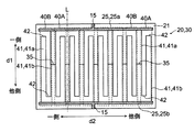
次に、図4を参照しながら、発熱用導電体30について説明する。図4は、導電体付きシート20をそのシート面の法線方向から見た平面図である。
Next, the
発熱用導電体30は、一対のバスバー25間を連結するように配置されており、一対のバスバー25を電気的に接続している。発熱用導電体30は、配線部15及びバスバー25を介して電圧を印加されると、抵抗加熱によって発熱する。そして、この熱が透明発熱体10の表面に伝わることで、透明発熱体10の表面を発熱させる。
The
また、発熱用導電体30は、複数の連結導電体40を有する。複数の連結導電体40の各々は、一対のバスバー25を連結している。連結導電体40は、全体として第1方向d1に延び、第1方向d1に非平行な第2方向d2に配列されている。図示された例において、各バスバーは、第2方向d2に延びている。また、第1方向d1と第2方向d2とは互いに直交している。
Further, the
なお、図4に示す連結導電体40の具体的な構成については、後述して詳しく説明する。
The specific configuration of the connecting
このようなバスバー25および発熱用導電体30の連結導電体40を構成するための材料としては、例えば、金、銀、銅、白金、アルミニウム、クロム、モリブデン、ニッケル、チタン、パラジウム、インジウム、タングステン等の金属、及び、これらの金属の1種以上を含んでなる合金の一以上を例示することができる。発熱用導電体30及びバスバー25は、同一の材料を用いて形成されていてもよいし、或いは、互いに異なる材料を用いて形成されていてもよい。
Examples of the material for forming the connecting
発熱用導電体30は、上述したように不透明な金属材料を用いて形成され得る。その一方で、発熱用導電体30によって覆われていない基材21上の領域の割合、すなわち非被覆率は、70%以上99%以下程度と高くなっている。また、連結導電体40の線幅Wは、20μm以下となっている。このため、発熱用導電体30が設けられている領域は、全体として透明に把握され、発熱用導電体30の存在が透明発熱体10の透視性を害さないようになっている。
The
上述したように、発熱用導電体30は、エンブレム5の第1領域5aに重なる位置より、第2領域5bに重なる位置により高い密度で配置されていることが好ましい。言い換えると、第1領域5aにおける連結導電体40の非被覆率は、第2領域5bにおける連結導電体40の非被覆率より高くなっていることが好ましい。また、発熱用導電体30は、第2領域5bに重なる位置にのみ配置されていることがより好ましい。言い換えると、第1領域5aが連結導電体40に被覆されていないこと、すなわち第1領域5aに連結導電体40が配置されていないことがより好ましい。第1領域5aにおける連結導電体40の非被覆率が高くなっていることで、より好ましくは第1領域5aに連結導電体40が配置されていないことで、エンブレム5の意匠性が、連結導電体40によって害されにくくなる。同様に、第1領域5aにおけるバスバー25の非被覆率が高くなっていることで、より好ましくは第1領域5aにバスバー25が配置されていないことで、エンブレム5の意匠性が、連結導電体40によって害されにくくなる。
As described above, it is preferable that the
図3に示された例では、連結導電体40は、全体として矩形状の断面を有している。連結導電体40の幅W、すなわち、透明発熱体10の板面に沿った幅Wは2μm以上20μm以下とし、高さ(厚さ)H、すなわち、透明発熱体10の板面への法線方向に沿った高さ(厚さ)Hは1μm以上60μm以下とすることが好ましい。このような寸法の連結導電体40によれば、その連結導電体40が十分に細線化されているので、発熱用導電体30を効果的に不可視化することができる。
In the example shown in FIG. 3, the connecting
また、図3に示されたように、連結導電体40は、導電性金属層46、導電性金属層46の表面のうち、基材21に対向する側の面を覆う第1の暗色層47、導電性金属層46の表面のうち、基材21に対向する側とは反対側の面及び両側面を覆う第2の暗色層48を含むようにしてもよい。優れた導電性を有する金属材料からなる導電性金属層46は、比較的高い反射率を呈する。そして、発熱用導電体30の連結導電体40をなす導電性金属層46によって光が反射されると、その反射した光が視認されるようになり、透明発熱体10が設けられたエンブレム5の意匠性を低下させてしまうことがある。そこで、第1及び第2の暗色層47,48が、導電性金属層46の表面の少なくとも一部分を覆っている。第1及び第2の暗色層47,48は、導電性金属層46よりも可視光の反射率が低い層であればよく、例えば黒色、濃灰色等の低明度無彩色、或いは褐色、紺色、濃緑色、濃紫色、臙脂色等の低明度有彩色等の暗色を呈する層である。又、暗色層の材料としては、黒色酸化鉄(Fe3O4)、カーボン(炭素)、酸化銅(酸化銅(II)CuO)、窒化銅、窒化酸化銅、銅−コバルト合金等を用いることができる。この暗色層47,48によって、導電性金属層46が視認されづらくなり、透明発熱体10が設けられたエンブレム5を外部から見たときの意匠性の低下を防ぐことができる。
Further, as shown in FIG. 3, the connecting
図3Aに示された例では、発熱用導電体30の基材21の側とは反対側が、エンブレム5と対面している。言い換えると、発熱用導電体30のエンブレム5と対面する側とは反対側、すなわち基材21の側が、外部から観察され得る。したがって、透明発熱体10が設けられたエンブレム5を外部から見たときの意匠性の低下を防ぐために、連結導電体40は、少なくともエンブレム5(カバー4)と対面する側とは反対側に、暗色層47を含んでいることが好ましい。また、バスバー25も同様に暗色層を含んでいることが好ましい。すなわち、透明発熱体10が設けられたエンブレム5を外部から見たときの意匠性の低下を防ぐために、バスバー25は、少なくともエンブレム5(カバー4)と対面する側とは反対側に、暗色層を含んでいることが好ましい。
In the example shown in FIG. 3A, the side of the
ところで、上述したように、本実施の形態の透明発熱体10は、自動車のエンブレム5上に設けられるよう、エンブレム5と同程度の大きさとなっている。すなわち、自動車のフロントガラス等として用いられていた従来の透明発熱体に比べて、透明発熱体10は小型の部材となっている。透明発熱体10が小さいと、発熱用導電体30を適切な抵抗値とすることが困難になり、透明発熱体10の抵抗加熱が不足することがあった。抵抗加熱を増加させるためには、発熱用導電体30の抵抗値を増加させることが求められる。そこで、発熱用導電体30の抵抗値を増加させるために、連結導電体40の断面積を小さくすること、すなわち連結導電体40の幅Wを狭くすることが考えられた。しかしながら、連結導電体40の幅Wを狭くしすぎると、連結導電体40の強度が不足し、透明発熱体10に衝撃が加わると連結導電体40が断線する虞が生じてしまう。したがって、連結導電体40の幅Wを調節するだけでは、発熱用導電体30に求められる抵抗値を達成することは困難であった。
By the way, as described above, the
発熱用導電体30を所望の抵抗値とするため、本実施の形態においては、図4に示すように、連結導電体40が第1方向d1へ少なくとも2回折り返される構成となっている。すなわち、連結導電体40は、第1方向d1の一側のバスバー25から他側のバスバー25へ延びる間において、第1方向d1の一側から他側へ延びた後、第1方向d1の他側から一側へ延び、再び第1方向d1の一側から他側へ延びる部分を、少なくとも含んでいる構成となっている。
In order to set the
このような連結導電体40によれば、折り返される位置や回数を調節することで、連結導電体40の経路長を長くして、発熱用導電体30の抵抗値を増加させることができる。ここで、連結導電体40の経路長とは、一方のバスバー25から他方のバスバー25までの連結導電体40に沿った長さ(全長)のことを意味する。連結導電体40の経路長を調節することで、発熱用導電体30の抵抗値を所望の値に適切に調節することができる。したがって、適切な抵抗値とすることができ、透明発熱体10を適切に発熱させることができる。
According to such a connecting
連結導電体40が第1方向d1へ少なくとも2回折り返される構成となるように、1つの連結導電体40は、少なくとも3つの線状部41と、2つの線状部41を接続する接続部42と、を含んでいる。線状部41は、一対のバスバーが離間して配置されている第1方向d1に延びている。すなわち、線状部41は、少なくとも第1方向d1に沿った長さを有している。複数の線状部41は、第2方向d2に配列される。
One connecting
このような連結導電体40において、ある接続部42が接続する線状部41の一方は、当該接続部42に接続する部分より第1方向d1の一側において直接的に、または他の接続部42および線状部41を介して間接的に、バスバー25の一方と接続している。当該接続部42が接続する線状部41の他方は、当該接続部42に接続する部分より第1方向d1の一側において直接的に、または他の接続部42および線状部41を介して間接的に、バスバー25の他方と接続している。図4に示された例においては、接続部42aが接続する2つの線状部41は、第1方向d1の一側に延びて、それぞれが別のバスバー25a、25bと接続している。言い換えると、一対のバスバー25を連結する連結導電体40は、接続部42aにおいて、第1方向d1の一側へ折り返されている。同様に、この接続部42とは別のある接続部42が接続する線状部41の一方は、当該接続部42に接続する部分より第1方向d1の他側において直接的に、または他の接続部42および線状部41を介して間接的に、バスバー25の他方と接続している。当該接続部42が接続する線状部41の他方は、当該接続部42に接続する部分より第1方向d1の他側において直接的に、または他の接続部42および線状部41を介して間接的に、バスバー25の他方と接続している。図4に示された例においては、接続部42bが接続する2つの線状部41は、第1方向d1の他側に延びて、それぞれが別のバスバー25a、25bと接続している。言い換えると、一対のバスバー25を連結する連結導電体40は、ある接続部42において、第1方向d1の他側へ折り返されている。以上のようにして、連結導電体40は、接続部42a、42bにおいて、第1方向d1へ少なくとも2回折り返されている。
In such a connecting
とりわけ、図4に示された例では、連結導電体40の接続部42は、第2方向d2において隣り合う線状部41を接続している。また、線状部41と接続部42とは、互いの端部において接続している。さらに、各連結導電体40において、線状部41のうち第2方向d2の最も一側に配置された線状部41aが、第1方向d1の一側に配置されたバスバー25aと接続しており、第2方向d2の最も他側に配置された線状部41bが、第1方向d1の他側に配置されたバスバー25bと接続している。連結導電体40が図4に示されているような構成であると、簡易な構成で複数の連結導電体40を折り返すことができる。すなわち、簡易な構成で、連結導電体40の経路長を調節し、発熱用導電体30の抵抗値を適切に調節することができる。
In particular, in the example shown in FIG. 4, the connecting
図4に示された連結導電体40に対しては、様々な変更を加えることができる。以下において、図5乃至図11に示されている連結導電体40の各変形例について、説明する。ただし、連結導電体40に加えられる変更は、以下の各変形例に限定されるものではない。
Various changes can be made to the connecting
(連結導電体の第1の変形例)
図5には、連結導電体40の第1の変形例が示されている。第1の変形例では、複数の連結導電体40は、第1群の連結導電体40Aと、第2群の連結導電体40Bと、を含んでいる。とりわけ図示された例では、複数の連結導電体40は、第1群の連結導電体40A及び第2群の連結導電体40Bのいずれかに分類される。第1群の連結導電体40Aにおいては、図4に示された連結導電体40と同様に、連結導電体40のうち第2方向d2の最も一側に配置された線状部41aが、第1方向d1の一側に配置されたバスバー25aと接続しており、第2方向d2の最も他側に配置された線状部41bが、第1方向d1の他側に配置されたバスバー25bと接続している。一方、第2群の連結導電体40Bにおいては、図4に示された連結導電体40とは逆に、連結導電体40のうち第2方向d2の最も一側に配置された線状部41aが、第1方向d1の他側に配置されたバスバー25bと接続しており、第2方向d2の最も他側に配置された線状部41bが、第1方向d1の一側に配置されたバスバー25aと接続している。
(First modification of the connecting conductor)
FIG. 5 shows a first modification of the connecting
また、第1の変形例において、発熱用導電体30は、隣り合う2つの連結導電体40を接続する接続導電体35をさらに有している。接続導電体35によって、隣り合う2つの連結導電体40は、電気的に接続される。このため、外部からの衝撃等によって、連結導電体40の一端から接続導電体35への接続箇所までの部分に断線が生じてしまっても、連結導電体40の他端から接続導電体35への接続箇所までの部分は、接続導電体35を介して、他の連結導電体40へ接続している。この結果、連結導電体40の他端から接続導電体35への接続箇所までの部分での発熱を維持することができる。
Further, in the first modification, the
なお、第1の変形例において、第1群の連結導電体40Aと、第2群の連結導電体40Bとは、第2方向d2において交互に配置されている。したがって、接続導電体35は、第1群の連結導電体40Aと第2群の連結導電体40Bとを接続している。
In the first modification, the connecting
さらに、接続導電体35が接続する一方の連結導電体40の、第1方向d1の一側のバスバー25aに接続している部分から接続導電体35に接続している部分までの抵抗値に対する、接続導電体35に接続している部分から第1方向d1の他側のバスバー25bに接続している部分までの抵抗値の比は、接続導電体35が接続する他方の連結導電体40の、第1方向d1の一側のバスバー25aに接続している部分から接続導電体35に接続している部分までの抵抗値に対する、接続導電体35に接続している部分から第1方向d1の他側のバスバー25bに接続している部分までの抵抗値の比と、等しくなっていることが好ましい。抵抗値の比に関するこの関係を満たすよう接続導電体35が設けられていることで、断線が生じていない場合には、接続導電体35に電流がほとんど流れなくなる。したがって、接続導電体35を設けたことによって第1群の連結導電体40Aおよび第2群の連結導電体40Bを流れる電流が変化せず、第1群の連結導電体40Aと第2群の連結導電体40Bとで、それぞれ意図された発熱を行うことができる。
Further, with respect to the resistance value of one of the connecting
とりわけ、抵抗値の比に関するこの関係は、接続導電体35で接続された2つの連結導電体40は、当該接続導電体35を通るある直線に対して、線対称になっていると、容易に満たすことができる。図5に示されている第1の変形例では、接続導電体35で接続された2つの連結導電体40は、接続導電体35の第2方向d2における中心を通り且つ第1方向d1に平行な方向に延びる直線Lに対して、線対称になっている。
In particular, this relationship with respect to the ratio of resistance values is readily apparent when the two connecting
なお、上述した2つの抵抗値の比が等しいとは、厳密に2つの抵抗値の比が同じ値をとることのみを意味するのではなく、第1群の連結導電体40Aと第2群の連結導電体40Bとのそれぞれにおいて意図された発熱を十分に行うことができる範囲で、接続導電体35に電流が流れることを許容する程度に、2つの抵抗値の比が異なっていることも含む。本実施の形態において、具体的には、上述した2つの抵抗値の比の一方が他方の10%以内であれば、2つの抵抗値の比が等しいと考えてよい。
Note that the equal ratio of the two resistance values described above does not mean that the ratio of the two resistance values is exactly the same, but that the
(連結導電体の第2の変形例)
図6には、連結導電体40の第2の変形例が示されている。図4に示された連結導電体40の例では、1つの連結導電体40が第2方向d2において配置されている領域と、他の1つの連結導電体40が第2方向d2において配置されている領域とは、それぞれ別の領域であり、重なっていない。しかしながら、第2の変形例では、1つの連結導電体40が第2方向d2において配置されている領域は、他の1つの連結導電体40が第2方向d2において配置されている領域と、一部分において重なっている。具体的な例として、図6に示されているように、連結導電体40aが第2方向d2において配置されている領域R1と、連結導電体40aと隣り合う連結導電体40bが第2方向d2において配置されている領域R2とは、領域R3の部分において重なっている。
(Second modification of the connecting conductor)
FIG. 6 shows a second modification of the connecting
図示されている例において、連結導電体40は、経路長の調節のために、一対のバスバー25の間の任意の位置、例えば中心付近で折り返されている。この例によれば、連結導電体40の経路長を、一対のバスバー25の間の長さの略奇数倍の長さ以外の長さに、容易に調節することができる。このような連結導電体40が存在すると、ある連結導電体40と別の連結導電体40とが第2方向d2において配置される領域がそれぞれ別の領域である場合、発熱用導電体30において連結導電体40が配置されていない領域が大きくできてしまうことになる。連結導電体40が配置されていない領域は、発熱することがないため、連結導電体40が配置されている領域と配置されていない領域との間で発熱むらが発生する。
In the illustrated example, the connecting
一方、連結導電体40の第2の変形例によれば、連結導電体40が折り返される位置が一対のバスバー25の間の任意の位置、例えば中心付近であったとしても、当該折り返される位置に対面する位置に他の連結導電体40が配置されることになる。このため、連結導電体40の経路長の調節のために、連結導電体40が一対のバスバー25の間の任意の位置で折り前されたとしても、連結導電体40が配置されていない領域を小さくすることができる。したがって、透明発熱体10の全体において発熱むらの発生を抑制し、透明発熱体10の全体を均一に発熱させることができる。また、発熱用導電体30の分布が均一化されるので、発熱用導電体30を視認されにくくすることもできる。
On the other hand, according to the second modification of the connecting
(連結導電体の第3の変形例)
図7および図8には、連結導電体40の第3の変形例が示されている。図7に示した第3の変形例の一例では、連結導電体40が、曲線の組み合わせである波線の形状を有している。しかしながら、これに限らず、連結導電体40は、他の例のように直線の形状を有していてもよいし、直線を組み合わせて折れ線の形状を有していてもよいし、曲線の形状を有していてもよい。あるいは、これらの形状の組み合わせの形状を有していてもよい。とりわけ、図8に示した第3の変形例の他の例のように、連結導電体40は、円弧を組み合わせた形状を有してもよい。図8に示した例では、連結導電体40は、同一の大きさの180°分の円弧を、隣り合う円弧と互いに逆向きなるように組み合わされた形状を有している。
(Third modification example of the connecting conductor)
7 and 8 show a third modification of the connecting
連結導電体40が直線、曲線、又は直線及び曲線の組み合わせの形状を有することで、連結導電体40の概形を変えることなく、連結導電体40の経路長を、適宜に調節することができる。したがって、連結導電体40を有する発熱用導電体30の抵抗値を調節することができる。また、後述する透明発熱体10をエンブレム5に設ける工程においてプレス成型された際に、透明発熱体10が連結導電体40の伸びている方向に変形したとしても、連結導電体40が切断されにくくなる。
Since the connecting
なお、連結導電体40の概形とは、当該連結導電体40に含まれる各線状部41及び接続部42が延びている長さ及び向きによって規定される連結導電体40のおおよその形状のことを意味している。
The general shape of the connecting
図9には、図8に示した連結導電体40の一部が拡大して示されている。連結導電体40が円弧を組み合わせた形状を有する場合、図9に示す連結導電体40の形状をなる1つの円弧の半径rと連結導電体40の幅Wとは、次の関係を満たす。
0.6≦(r−W)2/r2≦0.95
すなわち、1つの連結導電体40の非被覆率が60%以上95%以下となっている。このような関係を満たすことで、円弧を組み合わせた形状の連結導電体40が太く観察されにくくなり、したがって連結導電体40が視認されにくくなる。具体的な一例として、円弧の半径rが0.145mm、連結導電体40の幅Wが0.02mmの場合、連結導電体40の非被覆率は74%となる。なお、円弧の半径rは、連結導電体40の形成する円弧の中心から当該連結導電体40の外側の縁までの長さのことをいう。
FIG. 9 shows a part of the connecting
0.6 ≤ (r-W) 2 / r 2 ≤ 0.95
That is, the non-coating ratio of one connecting
(連結導電体の第4の変形例)
図10には、連結導電体40の第4の変形例が示されている。図10に示されている例では、透明発熱体10は、全体として六角形の形状となっている。また、一対のバスバー25が、透明発熱体10の形状に合わせて、折れ線状の形状を有している。すなわち、バスバー25は、連結導電体40の配列方向である第2方向d2に非平行な方向へ延びている。したがって、一対のバスバー25の間の第1方向d1における距離は、第2方向d2における各位置で一定とはならない。このため、一対のバスバー25を連結する複数の連結導電体40は、それぞれ経路長が異なる。
(Fourth modification of the connecting conductor)
FIG. 10 shows a fourth modification of the connecting
第4の変形例では、ある1つの連結導電体40の幅Wは、当該連結導電体40よりも経路長が短い他の1つの連結導電体40の幅Wより、広くなっている。図10に示されている例では、連結導電体40aの経路長は連結導電体40bの経路長より長く、連結導電体40bの経路長は、連結導電体40cの経路長より長くなっている。また、連結導電体40aの幅W1は連結導電体40bの幅W2より広く、連結導電体40bの幅W2は、連結導電体40cの幅W3より広くなっている。
In the fourth modification, the width W of one connecting
連結導電体40の抵抗値は、連結導電体40の経路長に比例し、連結導電体40の幅Wに反比例する。したがって、ある1つの連結導電体40の幅Wが当該連結導電体40よりも経路長が短い他の1つの連結導電体40の幅Wより広くなっていると、各連結導電体40の抵抗値を均一化することができる。とりわけ、連結導電体40の幅Wを経路長の2乗で割った値が一定となっていると、各連結導電体40において単位面積あたりに発生する熱を均一化することができ、透明発熱体10の全体を均一に発熱させることができる。
The resistance value of the connecting
(連結導電体のその他の変形例)
本実施の形態の透明発熱体10に含まれる連結導電体40は、図4乃至図10に示された例に限らず、例えば図11に示す連結導電体40a〜40eのような構成であってもよい。
(Other modifications of the connecting conductor)
The connecting
例えば、図4乃至図10に示された例では、連結導電体40は2回折り返されているが、図11に示されている連結導電体40aに示すように、連結導電体40は3回以上折り返されていてもよい。連結導電体40が折り返される回数によって、連結導電体40の経路長を調節し、連結導電体40の抵抗値を適切に調節することができる。
For example, in the examples shown in FIGS. 4 to 10, the connecting
また、図4乃至図10に示された例では、線状部41の端部と接続部42の端部とが接続しているが、図11に示されている連結導電体40bに示すように、線状部41の任意の位置と接続部42の任意の位置とが接続していてもよい。すなわち、線状部41及び接続部42は、それぞれが接続している部分から延び出ていてもよい。例えば、線状部41と接続部42とが交差していてもよい。線状部41及び接続部42が接続している部分から延び出ている部分は、一対のバスバー25と電気的に接続されないため、透明発熱体10の発熱に寄与しないダミー部43となる。このようなダミー部43を適切に設けることによって、発熱用導電体30の分布を均一化することができる。発熱用導電体30の分布が均一化されると、発熱用導電体30を視認されにくくなり、透明発熱体10の意匠性を向上させることができる。
Further, in the examples shown in FIGS. 4 to 10, the end portion of the
また、図4乃至図10に示された例では、1つの連結導電体40において2つの線状部41は1つの接続部42のみによって接続されているが、図11に示されている連結導電体40bのように、2つの線状部41が複数の接続部42によって接続されていてもよい。この場合、1つの接続部42が断線しても、連結導電体40の電気的な接続を維持することができる。
Further, in the example shown in FIGS. 4 to 10, in one connecting
さらに、図4乃至図10に示された例では、1つの連結導電体40において1つの線状部41のみが一方のバスバー25に接続しているが、図11に示されている連結導電体40bのように、1つの連結導電体40において複数の線状部41が一方のバスバー25に接続していてもよい。この場合、バスバー25に接続している線状部41の1つが断線しても、連結導電体40の電気的な接続を維持することができる。
Further, in the examples shown in FIGS. 4 to 10, only one
また、上述したダミー部43は、線状部41及び接続部42が接続している部分から延び出ている部分であるだけでなく、図11に示されている連結導電体40cのように、ある線状部41及び接続部42の全体であってもよい。
Further, the
さらに、図4乃至図10に示された例では、各連結導電体40において、線状部41のうち第2方向d2の最も一側に配置された線状部41が、一方のバスバー25と接続している。しかしながら、図11に示されている連結導電体40cのように、第2方向d2の最も一側に配置された線状部41以外の線状部41が、一方のバスバー25に接続していてもよい。
Further, in the examples shown in FIGS. 4 to 10, in each connecting
また、図4乃至図10に示された例では、接続部42は、第2方向d2において隣り合う2つの線状部41を接続しているが、図11に示されている連結導電体40dのように、接続部42が接続する2つの線状部41は、第2方向d2において隣り合っていなくてもよい。
Further, in the examples shown in FIGS. 4 to 10, the connecting
さらに、図4乃至図10に示された例では、「第1方向d1に延びる線状部41」は、第1方向d1と平行に延びているが、第1方向d1に沿った或る領域に存在していればよく、したがって第1方向d1に対して傾斜する方向と平行に延びていてもよい。言い換えると、線状部41は、第1方向d1に延びる成分を少なくとも含んでいればよい。すなわち、図11に示されている連結導電体40eに含まれている線状部41のように、第1方向d1に対して傾斜していてもよい。
Further, in the examples shown in FIGS. 4 to 10, the "
また、図4乃至図10に示された例では、接続部42は、線状に延びているが、図11に示されている連結導電体40eの接続部42のように、接続部42は、線状部41が接する点であってもよい。
Further, in the examples shown in FIGS. 4 to 10, the connecting
さらに、図5に示された例において、1つの第1群の連結導電体40Aと、1つの第2群の連結導電体40Bとが、交互に配置されている。しかしながら、複数の第1群の連結導電体40Aと、複数の第2群の連結導電体40Bとが、交互に配置されていてもよい。一例として、第1群に属する二つの連結導電体40Aと第2群に属する二つの連結導電体40Bが、第2方向d2に交互に配列されていてもよい。この例では、第2方向d2に隣り合う第1群の連結導電体40A及び第2群の連結導電体40Bを接続導電体35で接続するようにしてもよい。さらには、図5に示された例では、隣り合う2つの連結導電体40は1つの接続導電体35によって接続されているが、隣り合う2つの連結導電体40が複数の接続導電体35によって接続されていてもよい。
Further, in the example shown in FIG. 5, one first group of connecting
なお、連結導電体40は、当然に、以上の各例で示された構成を互いに組み合わせた構成を有することができる。
As a matter of course, the connecting
次に、透明発熱体10の製造方法の一例について、説明する。
Next, an example of a method for manufacturing the
まず、基材21上に第1の暗色層47を形成するようになる暗色膜を設ける。
First, a dark color film that forms the first
次に、導電性金属層46を形成するようになる金属膜を暗色膜上に設ける。金属膜は、公知の方法で形成され得る。例えば、銅箔等の金属箔を貼着する方法、電界めっき及び無電界めっきを含むめっき法、スパッタリング法、CVD法、PVD法、イオンプレーティング法、又はこれらの二以上を組み合わせた方法を採用することができる。
Next, a metal film that forms the
その後、金属膜上に、レジストパターンを設ける。レジストパターンは、形成されるべき発熱用導電体30に対応した形状となっている。このレジストパターンは、公知のフォトリソグラフィー技術を用いたパターニングにより形成することができる。
After that, a resist pattern is provided on the metal film. The resist pattern has a shape corresponding to the
次に、レジストパターンをマスクとして、金属膜及び暗色膜をエッチングする。このエッチングにより、金属膜及び暗色膜がレジストパターンと略同一のパターンにパターニングされる。この結果、パターニングされた金属膜から、連結導電体40の一部をなすようになる導電性金属層46が、形成される。また、パターニングされた暗色膜から、連結導電体40の一部をなすようになる第1の暗色層47が、形成される。
Next, the metal film and the dark color film are etched using the resist pattern as a mask. By this etching, the metal film and the dark color film are patterned in substantially the same pattern as the resist pattern. As a result, the
なお、エッチング方法は特に限られることはなく、公知の方法が採用できる。公知の方法としては、例えば、エッチング液を用いるウェットエッチングや、プラズマエッチングなどが挙げられる。その後、レジストパターンを除去する。 The etching method is not particularly limited, and a known method can be adopted. Known methods include, for example, wet etching using an etching solution, plasma etching, and the like. Then, the resist pattern is removed.
その後、導電性金属層46の第1の暗色層47が設けられた面と反対側の面及び側面に第2の暗色層48を形成する。第2の暗色層48は、例えば導電性金属層46をなす材料の一部分に暗色化処理(黒化処理)を施して、導電性金属層46をなしていた一部分から、金属酸化物や金属硫化物からなる第2の暗色層48を形成することができる。また、導電性金属層46の表面に第2の暗色層48を設けるようにしてもよい。また、導電性金属層46の表面を粗化して第2の暗色層48を設けるようにしてもよい。
After that, the second
以上の工程によって、基材21上に発熱用導電体30が形成され、導電体付きシート20が作製される。
By the above steps, the
最後に、導電体付きシート20を内部に埋め込むように、透明発熱体10が形成される。これにより、図3に示した透明発熱体10が作製される。この透明発熱体10は、例えばエンブレム5に対してプレス成型されることによって、エンブレム5上に設けられる。
Finally, the
以上のように、本実施の形態の透明発熱体10は、センサ8に対面して配置され、第1方向d1に離間して配置された一対のバスバー25と、一対のバスバー25を連結する発熱用導電体30と、を備え、発熱用導電体30は、各々が一対のバスバー25を連結する複数の連結導電体40を有し、連結導電体40は、第1方向d1に非平行な第2方向d2に配列され、第1方向d1へ少なくとも2回折り返されている。このような透明発熱体10によれば、連結導電体40の折り返される位置や回数を調節することで、連結導電体40の経路長を調節することができる。連結導電体40の経路長を調節することで、センサ8に対面して配置される透明発熱体10において、発熱用導電体30の抵抗値を所望の値に適切に調節することができる。発熱用導電体30の抵抗値を所望の値とすることで、透明発熱体10を適切に発熱させることができる。
As described above, the
なお、上述した実施の形態に対して様々な変更を加えることが可能である。以下、図面を参照しながら、変形の一例について説明する。以下の説明および以下の説明で用いる図面では、上述した実施の形態と同様に構成され得る部分について、上述の実施の形態における対応する部分に対して用いた符号と同一の符号を用いるとともに、重複する説明を省略する。 It is possible to make various changes to the above-described embodiment. Hereinafter, an example of modification will be described with reference to the drawings. In the following description and the drawings used in the following description, the same reference numerals as those used for the corresponding portions in the above-described embodiment are used for the portions that can be configured in the same manner as in the above-described embodiment, and duplicates are used. The explanation to be performed is omitted.
上述した実施の形態では、一対のバスバー25は、細長な板状に形成されていた。しかしながら、図12に示すように、バスバー25の少なくとも一方は、複数の開口部27を有するメッシュ状のパターンで線状導電体26を配置することで形成されていてもよい。バスバー25をこのような構成にすることで、バスバー25の透視性を向上させることができる。
In the above-described embodiment, the pair of
とりわけ、バスバー25の開口部27の第2方向d2における長さD1および第1方向d1における長さD3のうち少なくとも一方が、連結導電体40の第2方向d2において隣り合う2つの線状部41の距離D2と同一であることが好ましい。この場合、目視においてはバスバー25と連結導電体40の区別が付きにくくなる。したがって、バスバー25の存在が目立ちにくくなる。
In particular, at least one of the length D1 in the second direction d2 and the length D3 in the first direction d1 of the
また、線状導電体26の幅は、発熱用導電体30の連結導電体40の幅と同じであってもよいが、異なっていてもよい。線状導電体26の幅は、例えば、3μm以上50μm以下とすることが好ましい。このような寸法の線状導電体26によれば、その線状導電体26が十分に細線化されているので、バスバー25を効果的に不可視化することができる。
Further, the width of the
あるいは、線状導電体26の幅は、発熱用導電体30の連結導電体40の幅より大きくなっていることが好ましい。具体的には、線状導電体26の幅は、発熱用導電体30の連結導電体40の幅の2倍以上となっていることが好ましく、3倍以上となっていることがより好ましい。このような線状導電体26の幅は、例えば10μm以上80μm以下である。
Alternatively, the width of the
また、線状導電体26の断面積は、発熱用導電体30の断面積より大きくなっていることが好ましい。具体的には、線状導電体26の断面積は、発熱用導電体30の連結導電体40の断面積の2倍以上となっていることが好ましく、3倍以上となっていることがより好ましい。このような線状導電体26の断面積は、例えば10μm2以上4800μm2以下である。
Further, it is preferable that the cross section of the
特に透明発熱体10が小型の部材である場合、バスバー25は、狭い領域に配置され得る。バスバー25がメッシュ状のパターンで線状導電体26を配置することで形成されている場合、線状導電体26の密度が高くなり、バスバー25が発熱用導電体30より発熱してしまうことがある。発熱用導電体30が配置された領域が透明発熱体10における発熱させるべき領域であるため、バスバー25が発熱用導電体30より発熱してしまうことは好ましくない。そこで、上述したように、線状導電体26の幅が連結導電体40の幅より大きくなっていると、発熱用導電体30の抵抗に比べて、バスバー25の抵抗を低くすることができる。また、上述したように、線状導電体26の断面積が発熱用導電体30の断面積より大きくなっていると、発熱用導電体30の抵抗に比べて、バスバー25の抵抗を低くすることができる。バスバー25の抵抗を発熱用導電体30の抵抗より低くすることで、発熱用導電体30をバスバー25より発熱させることができる。これにより、透明発熱体10における発熱させるべき領域を効率よく発熱させることができる。
The
なお、図12に示された例では、バスバー25は、第1方向d1に延び且つ第2方向d2に配列されている線状導電体26と、第2方向d2に延び且つ第1方向d1に配列されている線状導電体26と、によって形成されている。さらに、バスバー25の開口部27の第2方向d2における長さD1と、連結導電体40の第2方向d2において隣り合う2つの線状部41の距離D2とは、第2方向d2において同一となっている。この場合、目視においてはバスバー25と連結導電体40の区別がより付きにくくなり、バスバー25をより目立ちにくくすることができる。
In the example shown in FIG. 12, the
ここで、バスバー25の開口部27の第2方向d2における長さD1および第1方向d1における長さD3のうち少なくとも一方と連結導電体40の第2方向d2において隣り合う2つの線状部41の距離D2とが同一であるとは、これらが厳密に同じ長さであることのみを意味するのではなく、連結導電体40の存在によってバスバー25が目立ちにくくなる程度に、これらの長さが異なっていることも含む。本変形例においては、具体的には、これらの長さの一方が他方の10%以内であれば、十分にバスバー25が目立ちにくくなるため、同一と考えてよい。
Here, at least one of the length D1 in the second direction d2 and the length D3 in the first direction d1 of the
また、バスバー25においても、図7に示された連結導電体40と同様に、線状導電体26は、直線、曲線、又は、直線及び曲線の組み合わせの形状を有していてもよい。とりわけ、図8に示された連結導電体40と同様に、図12Aに示すように、線状導電体26は、円弧を組み合わせた形状を有していてもよい。線状導電体26がこのような形状を有する場合、透明発熱体10をエンブレム5に設ける工程においてプレス成型された際に、透明発熱体10が変形したとしても、線状導電体26が切断されにくくなる。特に、バスバー25は、発熱用導電体30より透明発熱体10の周縁に配置されるため、透明発熱体10の製造工程において変形されやすく、したがって線状導電体26は切断されやすい。このため、線状導電体26が曲線または円弧を組み合わせた形状を有することで、線状導電体26が切断されにくくなる効果を、より顕著に奏することができる。
Further, in the
線状導電体26が円弧を組み合わせた形状を有する場合、図9に示す連結導電体40と同様に、線状導電体26の形状をなる1つの円弧の半径rと線状導電体26の幅Wとは、次の関係を満たすことが好ましい。
0.6≦(r−W)2/r2≦0.95
すなわち、1つの線状導電体26の非被覆率が60%以上95%以下となっている。このような関係を満たすことで、円弧を組み合わせた形状の線状導電体26が太く観察されにくくなり、したがって線状導電体26が視認されにくくなる。
When the
0.6 ≤ (r-W) 2 / r 2 ≤ 0.95
That is, the non-coating ratio of one
さらに、図示された例の透明発熱体10において、第1方向d1を縦方向、第2方向d2を横方向にしているが、これらは透明発熱体10を第1方向d1が鉛直方向、第2方向d2が水平方向となるように配置することのみを意味するものではない。透明発熱体10は、第1方向d1が鉛直方向、第2方向d2が水平方向となるように配置されていてもよいし、第1方向d1が水平方向、第2方向d2が鉛直方向となるように配置されていてもよいし、第1方向d1及び第2方向d2がともに水平方向に対しても鉛直方向に対しても傾斜した方向であってもよい。
Further, in the
なお、バスバー25が離間した方向である第1方向d1が水平方向または略水平方向である場合、バスバー25に接続した配線部15は、図10Aに示すように、バスバー25の鉛直方向の下側に延びていることが好ましい。エンブレム5は観察者より下方に配置されることが多いため、配線部15がバスバー25の下側に延びていると、配線部15が視認されにくくなり、透明発熱体10が配置されたエンブレム5の意匠性を害しにくくなる。
When the first direction d1 which is the direction in which the
また、上述した実施の形態では、透明発熱体10は、移動体1の衝突予防システムのレーダに対面するエンブレム5上に設けられている。しかしながら、透明発熱体10は、移動体1の他のセンサ8に対面して配置されてもよい。例えば、移動体1に設けられたカメラに対面して配置されてもよい。
Further, in the above-described embodiment, the
さらに、透明発熱体10は、移動体1以外にも、例えば建築物の外壁に設けられたセンサに対面して配置されてもよい。
Further, the
なお、以上において上述した実施の形態に対するいくつかの変形例を説明してきたが、当然に、複数の変形例を適宜組み合わせて適用することも可能である。 Although some modifications to the above-described embodiments have been described above, it is naturally possible to apply a plurality of modifications in combination as appropriate.
1 移動体
2 センサ装置
3 カバー付き発熱体
4 カバー
5 エンブレム
5a 第1領域
5b 第2領域
7 電源
8 センサ
10 透明発熱体
11 透明層
15 配線部
20 導電体付きシート
21 基材
25 バスバー
26 線状導電体
27 開口部
30 発熱用導電体
35 接続導電体
40 連結導電体
40A 第1群の連結導電体
40B 第2群の連結導電体
41 線状部
42 接続部
43 ダミー部
46 導電性金属層
47 第1の暗色層
48 第2の暗色層
1 Moving element 2
Claims (24)
前記カバー上に設けられた透明発熱体と、を備え、
前記透明発熱体は、センサに対面して配置される透明発熱体であって、第1方向に離間して配置された一対のバスバーと、前記一対のバスバーを連結する複数の連結導電体と、を有し、
前記連結導電体は、前記第1方向に非平行な第2方向に配列され、
前記連結導電体は、前記第1方向へ少なくとも2回折り返されており、
前記カバーは、第1領域と、前記第1領域より反射率が低い第2領域と、を含み、
前記透明発熱体の前記一対のバスバーは、前記第2領域に重なる位置にのみ配置され、
前記一対のバスバーは、前記カバーと対面する側とは反対側に暗色層を含む、カバー付き発熱体。 With the cover
A transparent heating element provided on the cover is provided.
The transparent heating element, a transparent heating element which is arranged facing the sensor, a plurality of connecting conductors for connecting a pair of bus bars which are spaced in a first direction, the pair of bus bars, Have ,
The connecting conductors are arranged in a second direction, which is non-parallel to the first direction.
The connecting conductor is folded back at least twice in the first direction .
The cover includes a first region and a second region having a lower reflectance than the first region.
The pair of busbars of the transparent heating element are arranged only at positions overlapping the second region.
The pair of bus bars is a heating element with a cover, which includes a dark layer on the side opposite to the side facing the cover.
前記カバー上に設けられた透明発熱体と、を備え、 A transparent heating element provided on the cover is provided.
前記透明発熱体は、センサに対面して配置される透明発熱体であって、第1方向に離間して配置された一対のバスバーと、前記一対のバスバーを連結する複数の連結導電体と、を有し、 The transparent heating element is a transparent heating element arranged to face the sensor, and includes a pair of bus bars arranged apart from each other in the first direction, and a plurality of connecting conductors connecting the pair of bus bars. Have,
前記連結導電体は、前記第1方向に非平行な第2方向に配列され、 The connecting conductors are arranged in a second direction, which is non-parallel to the first direction.
前記連結導電体は、前記第1方向へ少なくとも2回折り返されており、 The connecting conductor is folded back at least twice in the first direction.
前記カバーは、第1領域と、前記第1領域より反射率が低い第2領域と、を含み、 The cover includes a first region and a second region having a lower reflectance than the first region.
前記第1領域における前記連結導電体の非被覆率は、前記第2領域における前記連結導電体の非被覆率より高く、 The non-coating rate of the connecting conductor in the first region is higher than the non-covering rate of the connecting conductor in the second region.
前記連結導電体は、前記カバーと対面する側とは反対側に暗色層を含む、カバー付き発熱体。 The connecting conductor is a heating element with a cover, which includes a dark color layer on the side opposite to the side facing the cover.
前記第1群の連結導電体において、前記第2方向の最も一側に配置された前記線状部が、前記第1方向の一側に配置された前記バスバーに接続し、前記第2方向の最も他側に配置された前記線状部が、前記第1方向の他側に配置された前記バスバーに接続し、
前記第2群の連結導電体において、前記第2方向の最も一側に配置された前記線状部が、前記第1方向の他側に配置された前記バスバーに接続し、前記第2方向の最も他側に配置された前記線状部が、前記第1方向の一側に配置された前記バスバーに接続する、請求項4または5に記載のカバー付き発熱体。 The plurality of connecting conductors include a first group of connecting conductors and a second group of connecting conductors.
In the first group of connecting conductors, the linear portion arranged on the most one side in the second direction is connected to the bus bar arranged on one side in the first direction, and is connected to the bus bar in the second direction. The linear portion arranged on the other side is connected to the bus bar arranged on the other side in the first direction.
In the second group of connecting conductors, the linear portion arranged on the most one side in the second direction is connected to the bus bar arranged on the other side in the first direction, and is connected to the bus bar in the second direction. The covered heating element according to claim 4 or 5 , wherein the linear portion arranged on the other side is connected to the bus bar arranged on one side in the first direction.
前記開口部の前記第2方向における長さは、前記第2方向において隣り合う2つの前記線状部の距離と同一である、請求項4乃至11のいずれか一項に記載のカバー付き発熱体。 The bus bar is formed in a mesh-like pattern having a plurality of openings.
The covered heating element according to any one of claims 4 to 11 , wherein the length of the opening in the second direction is the same as the distance between two adjacent linear portions in the second direction. ..
前記線状導電体の幅は、前記連結導電体の幅より大きくなっている、請求項12または13に記載のカバー付き発熱体。 The mesh-like pattern is formed by arranging a plurality of linear conductors.
The heating element with a cover according to claim 12 or 13 , wherein the width of the linear conductor is larger than the width of the connecting conductor.
前記線状導電体の断面積は、前記連結導電体の断面積より大きくなっている、請求項12乃至14のいずれか一項に記載のカバー付き発熱体。 The mesh-like pattern is formed by arranging a plurality of linear conductors.
The heating element with a cover according to any one of claims 12 to 14 , wherein the cross section of the linear conductor is larger than the cross section of the connecting conductor.
前記線状導電体は、曲線、又は、直線及び曲線の組み合わせの形状を有する、請求項12乃至15のいずれか一項に記載のカバー付き発熱体。 The mesh-like pattern is formed by arranging a plurality of linear conductors.
The covered heating element according to any one of claims 12 to 15 , wherein the linear conductor has a curved line or a shape of a straight line and a combination of curved lines.
前記線状導電体は、円弧を組み合わせた形状を有する、請求項12乃至15のいずれか一項に記載のカバー付き発熱体。 The mesh-like pattern is formed by arranging a plurality of linear conductors.
The heating element with a cover according to any one of claims 12 to 15 , wherein the linear conductor has a shape in which arcs are combined.
前記センサに対面して配置された請求項1乃至22のいずれか一項に記載のカバー付き発熱体と、を備え、
前記センサは、前記カバー付き発熱体の前記透明発熱体に対面して配置される、センサ装置。 With the sensor
The covered heating element according to any one of claims 1 to 22 , which is arranged facing the sensor, is provided.
The sensor is a sensor device arranged so as to face the transparent heating element of the covered heating element.
Priority Applications (9)
| Application Number | Priority Date | Filing Date | Title |
|---|---|---|---|
| JP2018220599A JP6756356B2 (en) | 2017-11-27 | 2018-11-26 | Transparent heating element, heating element with cover, sensor device, moving body |
| US17/297,420 US20220039216A1 (en) | 2018-11-26 | 2019-11-26 | Transparent heating element, heating element with cover, sensor device, and mobile object |
| CA3120843A CA3120843A1 (en) | 2018-11-26 | 2019-11-26 | Transparent heating element, heating element with cover, sensor device, and mobile object |
| EP23188112.9A EP4246711A3 (en) | 2018-11-26 | 2019-11-26 | Transparent heating element, heating element with cover, sensor device, and mobile object |
| CN201980075955.4A CN113056960A (en) | 2018-11-26 | 2019-11-26 | Transparent heating element, heating element with cover, sensor device, and moving body |
| PCT/JP2019/046168 WO2020111060A1 (en) | 2018-11-26 | 2019-11-26 | Transparent heat generating body, heat generating body with cover, sensor device, and moving body |
| EP19889480.0A EP3890434A4 (en) | 2018-11-26 | 2019-11-26 | Transparent heat generating body, heat generating body with cover, sensor device, and moving body |
| KR1020217019446A KR20210092300A (en) | 2018-11-26 | 2019-11-26 | Transparent heating element, heating element with cover, sensor device, movable body |
| JP2020142970A JP7284939B2 (en) | 2017-11-27 | 2020-08-26 | Transparent heating element, heating element with cover, sensor device, moving body |
Applications Claiming Priority (3)
| Application Number | Priority Date | Filing Date | Title |
|---|---|---|---|
| JP2017227020 | 2017-11-27 | ||
| JP2017227020 | 2017-11-27 | ||
| JP2018220599A JP6756356B2 (en) | 2017-11-27 | 2018-11-26 | Transparent heating element, heating element with cover, sensor device, moving body |
Related Child Applications (1)
| Application Number | Title | Priority Date | Filing Date |
|---|---|---|---|
| JP2020142970A Division JP7284939B2 (en) | 2017-11-27 | 2020-08-26 | Transparent heating element, heating element with cover, sensor device, moving body |
Publications (3)
| Publication Number | Publication Date |
|---|---|
| JP2019096617A JP2019096617A (en) | 2019-06-20 |
| JP2019096617A5 JP2019096617A5 (en) | 2020-06-25 |
| JP6756356B2 true JP6756356B2 (en) | 2020-09-16 |
Family
ID=66971961
Family Applications (2)
| Application Number | Title | Priority Date | Filing Date |
|---|---|---|---|
| JP2018220599A Active JP6756356B2 (en) | 2017-11-27 | 2018-11-26 | Transparent heating element, heating element with cover, sensor device, moving body |
| JP2020142970A Active JP7284939B2 (en) | 2017-11-27 | 2020-08-26 | Transparent heating element, heating element with cover, sensor device, moving body |
Family Applications After (1)
| Application Number | Title | Priority Date | Filing Date |
|---|---|---|---|
| JP2020142970A Active JP7284939B2 (en) | 2017-11-27 | 2020-08-26 | Transparent heating element, heating element with cover, sensor device, moving body |
Country Status (7)
| Country | Link |
|---|---|
| US (1) | US20220039216A1 (en) |
| EP (2) | EP4246711A3 (en) |
| JP (2) | JP6756356B2 (en) |
| KR (1) | KR20210092300A (en) |
| CN (1) | CN113056960A (en) |
| CA (1) | CA3120843A1 (en) |
| WO (1) | WO2020111060A1 (en) |
Families Citing this family (8)
| Publication number | Priority date | Publication date | Assignee | Title |
|---|---|---|---|---|
| US11264691B2 (en) * | 2019-07-15 | 2022-03-01 | Kymeta Corporation | Ground plane heater |
| JP7407007B2 (en) * | 2020-02-07 | 2023-12-28 | 株式会社東海理化電機製作所 | Vehicle imaging device |
| US20230139564A1 (en) | 2020-03-16 | 2023-05-04 | Lintec Corporation | Pseudo sheet structure, sheet conductive member, and sensor device |
| JP2021166146A (en) * | 2020-04-07 | 2021-10-14 | 株式会社デンソー | Film heater |
| JP2021174690A (en) * | 2020-04-27 | 2021-11-01 | 豊田合成株式会社 | Heater sheet and onboard sensor cover |
| WO2022079999A1 (en) * | 2020-10-13 | 2022-04-21 | 東京コスモス電機株式会社 | Electronic component and method for producing same |
| JP7334713B2 (en) | 2020-11-24 | 2023-08-29 | トヨタ自動車株式会社 | Electromagnetic wave permeable heater |
| WO2023022159A1 (en) * | 2021-08-19 | 2023-02-23 | 大日本印刷株式会社 | Conductor |
Family Cites Families (30)
| Publication number | Priority date | Publication date | Assignee | Title |
|---|---|---|---|---|
| JPS57140255A (en) * | 1981-02-25 | 1982-08-30 | Nissan Motor Co Ltd | Hot wire type anti-mist window glass for vehicle |
| JPH041723A (en) * | 1990-04-19 | 1992-01-07 | Asahi Optical Co Ltd | Thermal writing type liquid crystal display device |
| AU707597B2 (en) * | 1994-09-28 | 1999-07-15 | Bsh Industries Limited | Antenna |
| JPH0961781A (en) * | 1995-08-29 | 1997-03-07 | Asahi Optical Co Ltd | Liquid crystal projecting device |
| JPH11135243A (en) * | 1997-10-28 | 1999-05-21 | Sharp Corp | Sheet-form heat generator |
| JP4054419B2 (en) * | 1997-11-12 | 2008-02-27 | 株式会社東海ヒット | microscope |
| US6452138B1 (en) * | 1998-09-25 | 2002-09-17 | Thermosoft International Corporation | Multi-conductor soft heating element |
| DE10126869A1 (en) * | 2001-06-01 | 2002-12-19 | Saint Gobain Sekurit D Gmbh | Electrically heated disc |
| DE112005001105A5 (en) * | 2004-03-08 | 2007-05-24 | W.E.T. Automotive Systems Ag | Flat heating element |
| DE102004050158B3 (en) * | 2004-10-15 | 2006-04-06 | Saint-Gobain Sekurit Deutschland Gmbh & Co. Kg | Transparent disc with a heatable coating |
| KR100789329B1 (en) * | 2005-10-29 | 2007-12-28 | 임정규 | Method of making invisible heating line on substrate and sticking type defroster using the substrate and defroster for glass window |
| KR101351148B1 (en) * | 2005-12-29 | 2014-01-14 | 엑사테크 엘.엘.씨. | Method of forming a window defroster |
| KR200425284Y1 (en) * | 2006-05-18 | 2006-09-05 | 김민정 | A carbon fiber heating element |
| US20110042370A1 (en) * | 2008-03-17 | 2011-02-24 | Lg Chem, Ltd. | Heating element and manufacturing method for same |
| JP2009259714A (en) * | 2008-04-18 | 2009-11-05 | Sharp Corp | Surface heat generating element, fixing device equipped with it, and image forming device |
| JP5220551B2 (en) * | 2008-10-27 | 2013-06-26 | 株式会社日本製鋼所 | Molding method and molding die for vehicle millimeter wave radar cover |
| JP2010251230A (en) * | 2009-04-20 | 2010-11-04 | Fujifilm Corp | Electric heating window glass |
| JP2016539667A (en) * | 2013-09-29 | 2016-12-22 | アボミナブル ラブス、エルエルシー | Multi-area heated protective glasses |
| KR101638244B1 (en) * | 2014-10-06 | 2016-07-08 | 서울과학기술대학교 산학협력단 | Planar heating element and method for manufacturing the same |
| JP6481386B2 (en) * | 2015-01-29 | 2019-03-13 | 大日本印刷株式会社 | Heating plate and vehicle |
| JP6387864B2 (en) * | 2015-03-06 | 2018-09-12 | 東芝ライテック株式会社 | Heater and image forming apparatus |
| JP6571550B2 (en) * | 2015-03-09 | 2019-09-04 | 株式会社ニューフレアテクノロジー | Heater and semiconductor manufacturing apparatus using the same |
| CN104869676A (en) * | 2015-04-24 | 2015-08-26 | 冯冠平 | Low-voltage transparent electrothermal film and preparation process thereof |
| JP2016223161A (en) * | 2015-05-29 | 2016-12-28 | 大日本印刷株式会社 | Transparent heating plate and window including transparent heating plate |
| JP2016223948A (en) | 2015-06-01 | 2016-12-28 | サカエ理研工業株式会社 | Vehicle radome and vehicle radar device |
| JP6579433B2 (en) * | 2015-08-21 | 2019-09-25 | 大日本印刷株式会社 | Transparent heating plate and vehicle with transparent heating plate |
| CN108293275B (en) * | 2015-11-17 | 2022-03-11 | 大日本印刷株式会社 | Heating electrode device, heating plate and conductive heating body |
| US11654658B2 (en) * | 2016-05-26 | 2023-05-23 | Nippon Sheet Glass Company, Limited | Laminated glass |
| US10651530B2 (en) * | 2016-06-01 | 2020-05-12 | Toyoda Gosei Co., Ltd. | Decorative component for vehicle |
| US10974661B2 (en) | 2016-10-21 | 2021-04-13 | Toyoda Gosei Co., Ltd. | Decorative part for vehicle and method for manufacturing same |
-
2018
- 2018-11-26 JP JP2018220599A patent/JP6756356B2/en active Active
-
2019
- 2019-11-26 CN CN201980075955.4A patent/CN113056960A/en active Pending
- 2019-11-26 EP EP23188112.9A patent/EP4246711A3/en active Pending
- 2019-11-26 KR KR1020217019446A patent/KR20210092300A/en active IP Right Grant
- 2019-11-26 CA CA3120843A patent/CA3120843A1/en active Pending
- 2019-11-26 US US17/297,420 patent/US20220039216A1/en active Pending
- 2019-11-26 WO PCT/JP2019/046168 patent/WO2020111060A1/en unknown
- 2019-11-26 EP EP19889480.0A patent/EP3890434A4/en active Pending
-
2020
- 2020-08-26 JP JP2020142970A patent/JP7284939B2/en active Active
Also Published As
| Publication number | Publication date |
|---|---|
| JP2019096617A (en) | 2019-06-20 |
| US20220039216A1 (en) | 2022-02-03 |
| KR20210092300A (en) | 2021-07-23 |
| EP4246711A2 (en) | 2023-09-20 |
| EP3890434A4 (en) | 2022-11-23 |
| JP2020191309A (en) | 2020-11-26 |
| JP7284939B2 (en) | 2023-06-01 |
| CN113056960A (en) | 2021-06-29 |
| EP4246711A8 (en) | 2023-12-27 |
| EP3890434A1 (en) | 2021-10-06 |
| CA3120843A1 (en) | 2020-06-04 |
| WO2020111060A1 (en) | 2020-06-04 |
| EP4246711A3 (en) | 2023-12-20 |
Similar Documents
| Publication | Publication Date | Title |
|---|---|---|
| JP6756356B2 (en) | Transparent heating element, heating element with cover, sensor device, moving body | |
| CN111133328B (en) | Vehicle decorative member | |
| ES2694780T3 (en) | Antenna optimized in the bandwidth by hybrid structure of planar and linear radiator | |
| JP6840452B2 (en) | Laminated glass and conductive heating element | |
| JP6913294B2 (en) | Heating plates, seats with conductors, windows for vehicles and buildings | |
| JP6814398B2 (en) | Vehicles with heating plates, conductive pattern sheets and heating plates | |
| JP6951674B2 (en) | Heat-generating conductors, sheets with conductors, heat-generating plates and vehicles | |
| JP2017210146A (en) | Pattern conductor, heating conductor, seat with conductor, heating plate, vehicle, and architectural structure | |
| KR20210132036A (en) | Pattern conductor, heating plate and moving body | |
| JP7316535B2 (en) | Heat-generating conductor, heat-generating plate, and method for producing heat-generating conductor | |
| JP6897706B2 (en) | Heat plate and vehicle | |
| JP6540037B2 (en) | Heater plate and vehicle | |
| JP6770703B2 (en) | Pattern conductors, heat-generating conductors, sheets with conductors, heat-generating plates, vehicles and buildings | |
| WO2023022159A1 (en) | Conductor | |
| JP7356640B2 (en) | Heat generating conductor, heat generating plate, moving object | |
| JP2018092881A (en) | Heating conductor, heating plate and vehicle | |
| JP6740715B2 (en) | Pattern conductors, conductors for heat generation, sheets with conductors, heat generating plates, vehicles and buildings | |
| JP2019066231A (en) | Electric wave transparent cover | |
| JP2022184524A (en) | Electric conductor, plyboard, and sensor system | |
| JP6814414B2 (en) | Window with transparent heating plate and transparent heating plate | |
| JP2022012773A (en) | Sheet with electric conductor, ply board and moving body | |
| JP2018055942A (en) | Heating conductor, sheet with conductor, heating plate, vehicle and architectural structure | |
| JP2021187712A (en) | Conductive substrate and ply board | |
| JP2022094697A (en) | Patterned conductor, sheet with conductor, transparent heating cover and method for manufacturing transparent heating cover | |
| JP6757515B2 (en) | Laminated glass and vehicles |
Legal Events
| Date | Code | Title | Description |
|---|---|---|---|
| A521 | Request for written amendment filed |
Free format text: JAPANESE INTERMEDIATE CODE: A523 Effective date: 20200514 |
|
| A621 | Written request for application examination |
Free format text: JAPANESE INTERMEDIATE CODE: A621 Effective date: 20200514 |
|
| A871 | Explanation of circumstances concerning accelerated examination |
Free format text: JAPANESE INTERMEDIATE CODE: A871 Effective date: 20200514 |
|
| A975 | Report on accelerated examination |
Free format text: JAPANESE INTERMEDIATE CODE: A971005 Effective date: 20200720 |
|
| TRDD | Decision of grant or rejection written | ||
| A01 | Written decision to grant a patent or to grant a registration (utility model) |
Free format text: JAPANESE INTERMEDIATE CODE: A01 Effective date: 20200728 |
|
| A61 | First payment of annual fees (during grant procedure) |
Free format text: JAPANESE INTERMEDIATE CODE: A61 Effective date: 20200810 |
|
| R150 | Certificate of patent or registration of utility model |
Ref document number: 6756356 Country of ref document: JP Free format text: JAPANESE INTERMEDIATE CODE: R150 |