JP6733209B2 - Sheet manufacturing equipment - Google Patents
Sheet manufacturing equipment Download PDFInfo
- Publication number
- JP6733209B2 JP6733209B2 JP2016028632A JP2016028632A JP6733209B2 JP 6733209 B2 JP6733209 B2 JP 6733209B2 JP 2016028632 A JP2016028632 A JP 2016028632A JP 2016028632 A JP2016028632 A JP 2016028632A JP 6733209 B2 JP6733209 B2 JP 6733209B2
- Authority
- JP
- Japan
- Prior art keywords
- unit
- web
- defibrated material
- manufacturing apparatus
- forming
- Prior art date
- Legal status (The legal status is an assumption and is not a legal conclusion. Google has not performed a legal analysis and makes no representation as to the accuracy of the status listed.)
- Active
Links
Images


Description
本発明は、シート製造装置およびシート製造方法に関する。 The present invention relates to a sheet manufacturing apparatus and a sheet manufacturing method.
従来、シート製造装置においては、繊維を含む原料を水に投入し、主に機械的作用により離解して、抄き直す、いわゆる湿式方式が採用されている。このような湿式方式のシート製造装置は、大量の水が必要であり、装置が大きくなる。さらに、水処理施設の整備のメンテナンスに手間がかかる上、乾燥工程に係るエネルギーが大きくなる。 2. Description of the Related Art Conventionally, in a sheet manufacturing apparatus, a so-called wet method has been adopted in which a raw material containing fibers is poured into water, disintegrated mainly by mechanical action, and paper is re-formed. Such a wet type sheet manufacturing apparatus requires a large amount of water, and the apparatus becomes large. Furthermore, the maintenance of the water treatment facility is time-consuming and the energy required for the drying process is large.
そこで、小型化、省エネルギーのために、水を極力利用しない乾式によるシート製造装置が提案されている。例えば特許文献1には、乾式解繊機において紙片を繊維状に解繊し、サイクロンにおいて繊維の脱墨を行い、脱墨された繊維を、フォーミングドラム表面の小孔スクリーンを通過させて、メッシュベルト上に堆積させ、紙を成形することが記載されている。
Therefore, in order to reduce the size and save energy, a dry type sheet manufacturing apparatus that does not use water as much as possible has been proposed. For example, in
しかしながら、特許文献1に記載されたシート製造装置では、フォーミングドラム表面の小孔スクリーンに一部の繊維が付着して目詰まりを生じさせる場合がある。目詰まりを生じた小孔は繊維が通過せず、目詰まりを生じていない小孔から繊維が通過するので、メッシュベルト上に解繊物を均一に分散させることが困難な場合がある。この状態で紙を成形すると密度や厚さが不均一な紙となってしまう。
However, in the sheet manufacturing apparatus described in
本発明のいくつかの態様に係る目的の1つは、密度および厚さの均一性が高いシートを製造することができるシート製造装置を提供することにある。また、本発明のいくつかの態様に係る目的の1つは、密度および厚さの均一性が高いシートを製造することができるシート製造方法を提供することにある。 One of objects of some aspects of the present invention is to provide a sheet manufacturing apparatus capable of manufacturing a sheet having high uniformity of density and thickness. Another object of some aspects of the present invention is to provide a sheet manufacturing method capable of manufacturing a sheet having high uniformity in density and thickness.
本発明は前述の課題の少なくとも一部を解決するためになされたものであり、以下の態様または適用例として実現することができる。 The present invention has been made to solve at least a part of the problems described above, and can be realized as the following aspects or application examples.
本発明に係るシート製造装置の一態様は、
繊維を含む原料を解繊物に解繊する解繊部と、
前記解繊部により解繊された前記解繊物を選別する選別部と、
前記選別部により選別された前記解繊物が堆積したウェブを形成するウェブ形成部と、
前記ウェブ形成部により形成された前記ウェブを分断して細分体を形成するための分断部と、
前記細分体を構成する前記解繊物を堆積させる堆積部と、
前記堆積部により堆積された前記解繊物を加圧加熱してシートを成形する形成部と、
を有する。
One aspect of the sheet manufacturing apparatus according to the present invention is
A defibration unit for defibrating a raw material containing fibers into a defibrated material,
A selection unit for selecting the defibrated material defibrated by the defibration unit,
A web forming unit that forms a web in which the defibrated material sorted by the sorting unit is deposited,
A dividing portion for dividing the web formed by the web forming portion to form a subdivided body,
A deposition unit that deposits the defibrated material that constitutes the subdivided body,
A forming unit that pressurizes and heats the defibrated material deposited by the deposition unit to form a sheet;
Have.
このようなシート製造装置では、例えば複数の解繊物が互いに絡み合って大きな塊状となった状態で堆積部に供給されることを抑制することができ、堆積部の網の目が目詰まりを起こすことを抑制することができる。したがって、このようなシート製造装置では、密度および厚さの均一性が高いシートを製造することができる。
本発明に係るシート製造装置の一態様は、
繊維を含む原料を解繊物に解繊する解繊部と、
前記解繊部により解繊された前記解繊物を選別する選別部と、
前記選別部により選別された前記解繊物が堆積したウェブを形成するウェブ形成部と、
前記ウェブ形成部により形成された前記ウェブを分断して細分体を形成する分断部と、
前記細分体を構成する前記解繊物を堆積させる堆積部と、
前記堆積部により堆積された前記解繊物を用いてシートを成形する形成部と、を有する。
In such a sheet manufacturing apparatus, for example, it is possible to prevent a plurality of defibrated materials from being entangled with each other and being supplied to the deposition unit in a large lump state, and the mesh of the deposition unit is clogged. Can be suppressed. Therefore, with such a sheet manufacturing apparatus, it is possible to manufacture a sheet having high uniformity in density and thickness.
One aspect of the sheet manufacturing apparatus according to the present invention is
A defibration unit for defibrating a raw material containing fibers into a defibrated material,
A selection unit for selecting the defibrated material defibrated by the defibration unit,
A web forming unit that forms a web in which the defibrated material sorted by the sorting unit is deposited,
A dividing portion that divides the web formed by the web forming portion to form a subdivided body,
A deposition unit that deposits the defibrated material that constitutes the subdivided body,
A forming unit for forming a sheet using the defibrated material accumulated by the accumulating unit.
本発明に係るシート製造装置において、
前記ウェブ形成部は、
前記ウェブが堆積される堆積面と、
前記堆積面に堆積された前記ウェブを、前記堆積面から剥離するための剥離部と、を有してもよい。
In the sheet manufacturing apparatus according to the present invention,
The web forming unit,
A deposition surface on which the web is deposited,
It may have a peeling part for peeling the web deposited on the deposition surface from the deposition surface.
このようなシート製造装置では、ウェブを堆積面から確実に剥離することができる。 With such a sheet manufacturing apparatus, the web can be reliably peeled from the deposition surface.
本発明に係るシート製造装置において、
前記分断部は、前記ウェブに接触することにより分断して細分体を形成するための突部を備えた回転体を含んでもよい。
In the sheet manufacturing apparatus according to the present invention,
The dividing section may include a rotating body having a protrusion for dividing the web by contacting the web to form a subdivided body.
このようなシート製造装置では、回転体により確実に細分体が形成されるため、複数の解繊物が互いに絡み合って大きな塊状となった状態で堆積部に供給されることを抑制することができる。 In such a sheet manufacturing apparatus, since the subdivided body is surely formed by the rotating body, it is possible to prevent the plurality of defibrated materials from being entangled with each other and being supplied to the deposition unit in a large lump state. ..
本発明に係るシート製造装置において、
前記ウェブ形成部は、前記堆積面を有するベルトと、前記ベルトが張架される少なくとも2つのローラーを有し、
前記剥離部は、固定板を有し、
前記固定板は、前記ローラーのうち前記回転体側に位置するローラーに対向し前記ベルトに接していてもよい。
In the sheet manufacturing apparatus according to the present invention,
The web forming unit includes a belt having the deposition surface and at least two rollers around which the belt is stretched,
The peeling section has a fixing plate,
The fixing plate may face a roller positioned on the rotating body side among the rollers and contact the belt.
このようなシート製造装置では、固定板を設けるだけで、剥離部を容易に構成することができる。 In such a sheet manufacturing apparatus, the peeling portion can be easily configured only by providing the fixing plate.
本発明に係るシート製造装置において、
前記剥離部は、前記回転体の近傍で前記ウェブが前記ベルトから離れる方向の気流を発生させる気流発生部を有していてもよい。
In the sheet manufacturing apparatus according to the present invention,
The peeling section may include an airflow generating section that generates an airflow in a direction in which the web separates from the belt near the rotating body.
このようなシート製造装置では、ウェブをベルトから確実に剥離することができる。 In such a sheet manufacturing apparatus, the web can be reliably separated from the belt.
本発明に係るシート製造装置において、
前記ウェブ形成部は、前記堆積面を有するベルトを有し、
前記ベルトの移動速度に応じて、前記回転体の回転速度を制御する制御部を有していてもよい。
In the sheet manufacturing apparatus according to the present invention,
The web forming unit has a belt having the deposition surface,
A control unit that controls the rotation speed of the rotating body according to the moving speed of the belt may be included.
このようなシート製造装置では、堆積部に供給される細分体の体積の変動を小さくすることができる。 In such a sheet manufacturing apparatus, it is possible to reduce fluctuations in the volume of the subdivided bodies supplied to the deposition unit.
本発明に係るシート製造装置において、
前記ウェブの厚さを検出する検出部を有し、
前記制御部は、前記検出部により検出された前記ウェブの厚さに基づいて、前記ベルトの移動速度を制御してもよい。
In the sheet manufacturing apparatus according to the present invention,
A detection unit for detecting the thickness of the web,
The control unit may control the moving speed of the belt based on the thickness of the web detected by the detection unit.
このようなシート製造装置では、堆積部に供給される単位時間当たりの解繊物の量の変動を小さくすることができる。 In such a sheet manufacturing apparatus, it is possible to reduce fluctuations in the amount of defibrated material supplied to the deposition unit per unit time.
本発明に係るシート製造装置において、
前記ウェブの厚さを検出する検出部と、
前記検出部により検出された前記ウェブの厚さに基づいて、前記回転体の回転速度を制御する制御部と、
を有していてもよい。
In the sheet manufacturing apparatus according to the present invention,
A detection unit for detecting the thickness of the web,
Based on the thickness of the web detected by the detection unit, a control unit for controlling the rotation speed of the rotating body,
May have.
このようなシート製造装置では、堆積部に供給される細分体の体積の変動を小さくすることができる。 In such a sheet manufacturing apparatus, it is possible to reduce fluctuations in the volume of the subdivided bodies supplied to the deposition unit.
本発明に係るシート製造装置において、
前記剥離部は、気流発生部を有し、当該気流発生部が発生させる気流により、前記ウェブを前記堆積面から剥離してもよい。
In the sheet manufacturing apparatus according to the present invention,
The peeling section may include an airflow generating section, and the web may be peeled from the deposition surface by an airflow generated by the airflow generating section.
このようなシート製造装置では、堆積面に接触することなくウェブを剥離させることができる。これにより、堆積面への負荷を抑えることができる。 With such a sheet manufacturing apparatus, the web can be peeled off without contacting the deposition surface. Thereby, the load on the deposition surface can be suppressed.
本発明に係るシート製造装置において、
前記気流発生部は、前記堆積面に対して鋭角に、気流を当ててもよい。
In the sheet manufacturing apparatus according to the present invention,
The airflow generation unit may apply an airflow at an acute angle to the deposition surface.
このようなシート製造装置では、堆積面からウェブを効率良く剥離させることができる。 With such a sheet manufacturing apparatus, the web can be efficiently separated from the deposition surface.
本発明に係るシート製造装置において、
前記気流発生部が発生させる気流により、前記堆積面から剥離された前記ウェブは、前記ウェブの搬送方向に略平行な方向に分断されてもよい。
In the sheet manufacturing apparatus according to the present invention,
The web separated from the deposition surface may be divided in a direction substantially parallel to the transport direction of the web by the airflow generated by the airflow generation unit.
このようなシート製造装置では、細分体の体積を小さくし堆積部への供給(搬送)を容易にすることができる。 In such a sheet manufacturing apparatus, it is possible to reduce the volume of the subdivided body and facilitate the supply (conveyance) to the deposition unit.
本発明に係るシート製造装置において、
前記堆積面に当てる気流は、調湿されていてもよい。
In the sheet manufacturing apparatus according to the present invention,
The airflow applied to the deposition surface may be conditioned.
このようなシート製造装置では、ウェブの帯電が抑制され、堆積面からウェブを剥離させやすくすることができる。 In such a sheet manufacturing apparatus, electrification of the web is suppressed, and the web can be easily separated from the deposition surface.
本発明に係るシート製造装置において、
前記分断部は、前記ウェブを吸引することにより分断して細分体を形成するための吸引部を含んでもよい。
In the sheet manufacturing apparatus according to the present invention,
The dividing section may include a suction section for dividing the web by suction to form a subdivided body.
このようなシート製造装置では、堆積面から剥離されたウェブを吸引することにより、細分体が形成されるため、複数の解繊物が互いに絡み合って大きな塊状となった状態で堆積部に供給されることを抑制することができる。 In such a sheet manufacturing apparatus, since the subdivided body is formed by sucking the web separated from the deposition surface, the plurality of defibrated materials are entangled with each other and supplied to the deposition unit in a large lump state. Can be suppressed.
本発明に係るシート製造装置において、
前記ウェブ形成部は、前記堆積面を有するベルトと、前記ベルトを支持する支持部と、前記ベルトを間に前記支持部と対向する回転ローラーと、を有し、
前記堆積面に堆積されたウェブは、前記支持部と前記回転ローラーとにより挟持され、
前記剥離部は、前記支持部よりも前記ウェブの搬送方向の下流側で、前記気流発生部が発生させる気流を前記堆積面に当てて、前記ウェブを前記堆積面から剥離し、
前記分断部は、前記剥離部により剥離されたウェブを、前記吸引部により吸引してもよい。
In the sheet manufacturing apparatus according to the present invention,
The web forming unit includes a belt having the deposition surface, a support unit that supports the belt, and a rotating roller that faces the support unit with the belt interposed therebetween.
The web deposited on the deposition surface is sandwiched by the support portion and the rotating roller,
The peeling portion, on the downstream side in the transport direction of the web with respect to the support portion, the airflow generated by the airflow generating portion is applied to the deposition surface to peel the web from the deposition surface,
The dividing unit may suck the web peeled by the peeling unit by the suction unit.
このようなシート製造装置では、堆積面においてウェブが支持部と回転ローラーとにより挟持された状態で気流を当てることにより、ウェブが堆積面から剥離する位置(剥離される量)を安定させることができる。そして、堆積面から剥離させたウェブを吸引することによって形成される細分体の体積の変動を小さくすることができる。 In such a sheet manufacturing apparatus, it is possible to stabilize the position where the web is peeled from the deposition surface (amount of peeling) by applying an air flow in a state where the web is sandwiched between the support portion and the rotating roller on the deposition surface. it can. Then, it is possible to reduce the fluctuation of the volume of the subdivided body formed by sucking the web separated from the deposition surface.
本発明に係るシート製造装置において、
前記気流発生部による風量よりも前記吸引部による風量の方が大きくてもよい。
In the sheet manufacturing apparatus according to the present invention,
The air volume generated by the suction unit may be larger than the air volume generated by the air flow generation unit.
このようなシート製造装置では、気流発生部の気流による解繊物の飛散等を抑制することができる。 In such a sheet manufacturing apparatus, it is possible to suppress scattering of defibrated material due to the airflow of the airflow generation unit.
本発明に係るシート製造装置において、
前記細分体に添加物を供給する供給部を有していてもよい。
In the sheet manufacturing apparatus according to the present invention,
You may have the supply part which supplies an additive to the said granule.
このようなシート製造装置では、解繊物と添加物とを均一性よく混合することができる。 In such a sheet manufacturing apparatus, the defibrated material and the additive can be mixed with good uniformity.
本発明に係るシート製造装置において、
前記ウェブ形成部は、
前記ウェブが堆積されるメッシュベルトと、
前記ウェブが堆積される前記メッシュベルトの面とは反対側の面から、前記選別部により選別された前記解繊物を吸引する吸引部と、
を有していてもよい。
In the sheet manufacturing apparatus according to the present invention,
The web forming unit,
A mesh belt on which the web is deposited,
From a surface opposite to the surface of the mesh belt on which the web is deposited, a suction unit that sucks the defibrated material selected by the selection unit,
May have.
このようなシート製造装置では、選別部を通過した選別物(第1選別物)に含まれる色剤等の異物を除去することができる。 With such a sheet manufacturing apparatus, it is possible to remove foreign matters such as colorants contained in the sorted material (first sorted material) that has passed through the sorting unit.
本発明に係るシート製造方法の一態様は、
繊維を含む原料を解繊物に解繊する工程と、
解繊された前記解繊物を選別する工程と、
選別された前記解繊物が堆積したウェブを形成する工程と、
前記ウェブを分断して細分体を形成する工程と、
前記細分体を構成する前記解繊物を堆積する工程と、
堆積された前記解繊物を加圧加熱してシートを成形する工程と、
を有する。
One aspect of the sheet manufacturing method according to the present invention is
A step of defibrating a raw material containing fibers into a defibrated material,
A step of selecting the defibrated defibrated material,
Forming a web on which the defibrated material that has been sorted is deposited;
Dividing the web to form subdivisions;
Depositing the defibrated material constituting the subdivided body,
A step of heating the deposited defibrated material under pressure to form a sheet,
Have.
このようなシート製造方法では、密度および厚さの均一性が高いシートを製造することができる。
本発明に係るシート製造方法の一態様は、
繊維を含む原料を解繊物に解繊する工程と、
解繊された前記解繊物を選別する工程と、
選別された前記解繊物が堆積したウェブを形成する工程と、
前記ウェブを分断して細分体を形成する工程と、
前記細分体を構成する前記解繊物を堆積する工程と、
堆積された前記解繊物を用いてシートを成形する工程と、を有する。
また、本発明に係るシート製造装置の一態様は、
繊維を含む原料を解繊物に解繊する解繊部と、
前記解繊部により解繊された前記解繊物を選別する選別部と、
前記選別部により選別された前記解繊物が堆積したウェブを形成するウェブ形成部と、
前記ウェブ形成部により形成された前記ウェブを分断して細分体を形成する分断部と、
前記細分体を構成する前記解繊物を堆積させる堆積部と、
前記堆積部により堆積された前記解繊物を用いてシートを成形する形成部と、を有し、
前記ウェブ形成部は、
前記ウェブが堆積される堆積面と、
前記堆積面に堆積された前記ウェブを、前記堆積面から剥離するための剥離部と、を有し、
前記分断部は、前記ウェブに接触することにより分断して細分体を形成するための突部を備えた回転体と、を有し、
前記ウェブ形成部は、前記堆積面を有するベルトと、前記ベルトが張架される少なくとも2つのローラーを有し、
前記剥離部は、固定板を有し、
前記固定板は、前記ローラーのうち前記回転体側に位置するローラーに対向し前記ベルトに接する。
また、本発明に係るシート製造装置の一態様は、
繊維を含む原料を解繊物に解繊する解繊部と、
前記解繊部により解繊された前記解繊物を選別する選別部と、
前記選別部により選別された前記解繊物が堆積したウェブを形成するウェブ形成部と、
前記ウェブ形成部により形成された前記ウェブを分断して細分体を形成する分断部と、
前記細分体を構成する前記解繊物を堆積させる堆積部と、
前記堆積部により堆積された前記解繊物を用いてシートを成形する形成部と、を有し、
前記ウェブ形成部は、
前記ウェブが堆積される堆積面と、
前記堆積面に堆積された前記ウェブを、前記堆積面から剥離するための剥離部と、を有し、
前記分断部は、前記ウェブに接触することにより分断して細分体を形成するための突部を備えた回転体と、を有し、
前記剥離部は、前記回転体の近傍で前記ウェブが前記ベルトから離れる方向の気流を発生させる気流発生部を有する。
また、本発明に係るシート製造装置の一態様は、
繊維を含む原料を解繊物に解繊する解繊部と、
前記解繊部により解繊された前記解繊物を選別する選別部と、
前記選別部により選別された前記解繊物が堆積したウェブを形成するウェブ形成部と、
前記ウェブ形成部により形成された前記ウェブを分断して細分体を形成する分断部と、
前記細分体を構成する前記解繊物を堆積させる堆積部と、
前記堆積部により堆積された前記解繊物を用いてシートを成形する形成部と、を有し、
前記ウェブ形成部は、
前記ウェブが堆積される堆積面と、
前記堆積面に堆積された前記ウェブを、前記堆積面から剥離するための剥離部と、を有し、
前記分断部は、前記ウェブに接触することにより分断して細分体を形成するための突部を備えた回転体と、を有し、
前記ウェブ形成部は、前記堆積面を有するベルトを有し、
前記ベルトの移動速度に応じて、前記回転体の回転速度を制御する制御部を有する。
また、本発明に係るシート製造装置の一態様は、
繊維を含む原料を解繊物に解繊する解繊部と、
前記解繊部により解繊された前記解繊物を選別する選別部と、
前記選別部により選別された前記解繊物が堆積したウェブを形成するウェブ形成部と、
前記ウェブ形成部により形成された前記ウェブを分断して細分体を形成する分断部と、
前記細分体を構成する前記解繊物を堆積させる堆積部と、
前記堆積部により堆積された前記解繊物を用いてシートを成形する形成部と、を有し、
前記ウェブ形成部は、
前記ウェブが堆積される堆積面と、
前記堆積面に堆積された前記ウェブを、前記堆積面から剥離するための剥離部と、を有し、
前記分断部は、前記ウェブに接触することにより分断して細分体を形成するための突部を備えた回転体と、を有し、
前記ウェブの厚さを検出する検出部と、
前記検出部により検出された前記ウェブの厚さに基づいて、前記回転体の回転速度を制御する制御部と、を有する。
また、本発明に係るシート製造装置の一態様は、
繊維を含む原料を解繊物に解繊する解繊部と、
前記解繊部により解繊された前記解繊物を選別する選別部と、
前記選別部により選別された前記解繊物が堆積したウェブを形成するウェブ形成部と、
前記ウェブ形成部により形成された前記ウェブを分断して細分体を形成する分断部と、
前記細分体を構成する前記解繊物を堆積させる堆積部と、
前記堆積部により堆積された前記解繊物を用いてシートを成形する形成部と、を有し、
前記ウェブ形成部は、
前記ウェブが堆積される堆積面と、
前記堆積面に堆積された前記ウェブを、前記堆積面から剥離するための剥離部と、を有し、
前記分断部は、前記ウェブに接触することにより分断して細分体を形成するための突部を備えた回転体と、を有し、
前記剥離部は、気流発生部を有し、
前記気流発生部は、前記堆積面に対して鋭角に発生させる気流により、前記ウェブを前記堆積面から剥離する。
また、本発明に係るシート製造装置の一態様は、
繊維を含む原料を解繊物に解繊する解繊部と、
前記解繊部により解繊された前記解繊物を選別する選別部と、
前記選別部により選別された前記解繊物が堆積したウェブを形成するウェブ形成部と、
前記ウェブ形成部により形成された前記ウェブを分断して細分体を形成する分断部と、
前記細分体を構成する前記解繊物を堆積させる堆積部と、
前記堆積部により堆積された前記解繊物を用いてシートを成形する形成部と、
前記細分体が供給され前記堆積部に接続されている管と、
前記管から前記細分体を前記堆積部に搬送するブロアーと、
を有し、
前記分断部は、前記ウェブに接触することにより分断して細分体を形成するための突部を備えた回転体である。
With such a sheet manufacturing method, it is possible to manufacture a sheet having high uniformity in density and thickness.
One aspect of the sheet manufacturing method according to the present invention is
A step of defibrating a raw material containing fibers into a defibrated material,
A step of selecting the defibrated defibrated material,
Forming a web on which the defibrated material that has been sorted is deposited;
Dividing the web to form subdivisions;
Depositing the defibrated material constituting the subdivided body,
Forming a sheet using the accumulated defibrated material.
Further, one aspect of the sheet manufacturing apparatus according to the present invention is
A defibration unit for defibrating a raw material containing fibers into a defibrated material,
A selection unit for selecting the defibrated material defibrated by the defibration unit,
A web forming unit that forms a web in which the defibrated material sorted by the sorting unit is deposited,
A dividing portion that divides the web formed by the web forming portion to form a subdivided body,
A deposition unit that deposits the defibrated material that constitutes the subdivided body,
A forming unit for forming a sheet using the defibrated material accumulated by the accumulation unit,
The web forming unit,
A deposition surface on which the web is deposited,
A stripping portion for stripping the web deposited on the deposition surface from the deposition surface,
The dividing section includes a rotating body having a protrusion for forming a subdivided body by being divided by contacting the web,
The web forming unit includes a belt having the deposition surface and at least two rollers around which the belt is stretched,
The peeling section has a fixing plate,
The fixing plate faces a roller of the rollers located on the rotating body side and is in contact with the belt.
Further, one aspect of the sheet manufacturing apparatus according to the present invention is
A defibration unit for defibrating a raw material containing fibers into a defibrated material,
A selection unit for selecting the defibrated material defibrated by the defibration unit,
A web forming unit that forms a web in which the defibrated material sorted by the sorting unit is deposited,
A dividing portion that divides the web formed by the web forming portion to form a subdivided body,
A deposition unit that deposits the defibrated material that constitutes the subdivided body,
A forming unit for forming a sheet using the defibrated material accumulated by the accumulation unit,
The web forming unit,
A deposition surface on which the web is deposited,
A stripping portion for stripping the web deposited on the deposition surface from the deposition surface,
The dividing section includes a rotating body having a protrusion for forming a subdivided body by being divided by contacting the web,
The peeling section includes an airflow generation section that generates an airflow in a direction in which the web separates from the belt near the rotating body.
Further, one aspect of the sheet manufacturing apparatus according to the present invention is
A defibration unit for defibrating a raw material containing fibers into a defibrated material,
A selection unit for selecting the defibrated material defibrated by the defibration unit,
A web forming unit that forms a web in which the defibrated material sorted by the sorting unit is deposited,
A dividing portion that divides the web formed by the web forming portion to form a subdivided body,
A deposition unit that deposits the defibrated material that constitutes the subdivided body,
A forming unit for forming a sheet using the defibrated material accumulated by the accumulation unit,
The web forming unit,
A deposition surface on which the web is deposited,
A stripping portion for stripping the web deposited on the deposition surface from the deposition surface,
The dividing section includes a rotating body having a protrusion for forming a subdivided body by being divided by contacting the web,
The web forming unit has a belt having the deposition surface,
It has a control part which controls the rotation speed of the rotating body according to the moving speed of the belt.
Further, one aspect of the sheet manufacturing apparatus according to the present invention is
A defibration unit for defibrating a raw material containing fibers into a defibrated material,
A selection unit for selecting the defibrated material defibrated by the defibration unit,
A web forming unit that forms a web in which the defibrated material sorted by the sorting unit is deposited,
A dividing portion that divides the web formed by the web forming portion to form a subdivided body,
A deposition unit that deposits the defibrated material that constitutes the subdivided body,
A forming unit for forming a sheet using the defibrated material accumulated by the accumulation unit,
The web forming unit,
A deposition surface on which the web is deposited,
A stripping portion for stripping the web deposited on the deposition surface from the deposition surface,
The dividing section includes a rotating body having a protrusion for forming a subdivided body by being divided by contacting the web,
A detection unit for detecting the thickness of the web,
A control unit that controls the rotation speed of the rotating body based on the thickness of the web detected by the detection unit.
Further, one aspect of the sheet manufacturing apparatus according to the present invention is
A defibration unit for defibrating a raw material containing fibers into a defibrated material,
A selection unit for selecting the defibrated material defibrated by the defibration unit,
A web forming unit that forms a web in which the defibrated material sorted by the sorting unit is deposited,
A dividing portion that divides the web formed by the web forming portion to form a subdivided body,
A deposition unit that deposits the defibrated material that constitutes the subdivided body,
A forming unit for forming a sheet using the defibrated material accumulated by the accumulation unit,
The web forming unit,
A deposition surface on which the web is deposited,
A stripping portion for stripping the web deposited on the deposition surface from the deposition surface,
The dividing section includes a rotating body having a protrusion for forming a subdivided body by being divided by contacting the web,
The peeling section has an airflow generating section,
The airflow generation unit separates the web from the deposition surface by an airflow generated at an acute angle with respect to the deposition surface.
Further, one aspect of the sheet manufacturing apparatus according to the present invention is
A defibration unit for defibrating a raw material containing fibers into a defibrated material,
A selection unit for selecting the defibrated material defibrated by the defibration unit,
A web forming unit that forms a web in which the defibrated material sorted by the sorting unit is deposited,
A dividing portion that divides the web formed by the web forming portion to form a subdivided body,
A deposition unit that deposits the defibrated material that constitutes the subdivided body,
A forming unit that forms a sheet using the defibrated material accumulated by the accumulation unit,
A tube supplied with the subdivided body and connected to the deposition section;
A blower that conveys the subdivided body from the tube to the deposition unit,
Have
The dividing portion is a rotating body having a protrusion for dividing the web by contacting the web to form a subdivided body.
以下、本発明の好適な実施形態について、図面を用いて詳細に説明する。なお、以下に説明する実施形態は、特許請求の範囲に記載された本発明の内容を不当に限定するものではない。また、以下で説明される構成の全てが本発明の必須構成要件であるとは限らない。 Hereinafter, preferred embodiments of the present invention will be described in detail with reference to the drawings. It should be noted that the embodiments described below do not unduly limit the content of the invention described in the claims. In addition, not all of the configurations described below are essential configuration requirements of the invention.
1. 第1実施形態
1.1. シート製造装置
1.1.1. 構成
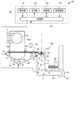
まず、第1実施形態に係るシート製造装置について、図面を参照しながら説明する。図1は、第1実施形態に係るシート製造装置100を模式的に示す図である。
1. 1. First Embodiment 1.1. Sheet manufacturing apparatus 1.1.1. Configuration First, the sheet manufacturing apparatus according to the first embodiment will be described with reference to the drawings. FIG. 1 is a diagram schematically showing a
シート製造装置100は、図1に示すように、供給部10と、製造部102と、制御部140と、を備える。製造部102は、シートを製造する。製造部102は、粗砕部12と、解繊部20と、選別部40と、第1ウェブ形成部45(ウェブ形成部)と、混合部50と、堆積部60と、第2ウェブ形成部70と、シート形成部80(形成部)と、切断部90と、を有している。
As shown in FIG. 1, the
供給部10は、粗砕部12に原料を供給する。供給部10は、例えば、粗砕部12に原料を連続的に投入するための自動投入部である。供給部10によって供給される原料は、例えば、古紙やパルプシートなどの繊維を含むものである。
The
粗砕部12は、供給部10によって供給された原料を、空気中で裁断して細片にする。細片の形状や大きさは、例えば、数cm角の細片である。図示の例では、粗砕部12は、粗砕刃14を有し、粗砕刃14によって、投入された原料を裁断することができる。粗砕部12としては、例えば、シュレッダーを用いる。粗砕部12によって裁断された原料は、ホッパー1で受けてから管2を介して、解繊部20に移送(搬送)される。
The crushing
解繊部20は、粗砕部12によって裁断された原料を解繊する。ここで、「解繊する」とは、複数の繊維が結着されてなる原料(被解繊物)を、繊維1本1本に解きほぐすことをいう。解繊部20は、原料に付着した樹脂粒やインク、トナー、にじみ防止剤等の物質を、繊維から分離させる機能をも有する。
The
解繊部20を通過したものを「解繊物」という。「解繊物」には、解きほぐされた解繊物繊維の他に、繊維を解きほぐす際に繊維から分離した樹脂(複数の繊維同士を結着させるための樹脂)粒や、インク、トナーなどの色剤や、にじみ防止材、紙力増強剤等の添加剤を含んでいる場合もある。解きほぐされた解繊物の形状は、ひも(string)状や平ひも(ribbon)状である。解きほぐされた解繊物は、他の解きほぐされた繊維と絡み合っていない状態(独立した状態)で存在してもよいし、他の解きほぐされた解繊物と絡み合って塊状となった状態(いわゆる「ダマ」を形成している状態)で存在してもよい。
What has passed through the
解繊部20は、大気中(空気中)において乾式で解繊を行う。具体的には、解繊部20としては、インペラーミルを用いる。解繊部20は、原料を吸引し、解繊物を排出するような気流を発生させる機能を有している。これにより、解繊部20は、自ら発生する気流によって、導入口22から原料を気流と共に吸引し、解繊処理して、解繊物を排出口24へと搬送することができる。解繊部20を通過した解繊物は、管3を介して、選別部40に移送される。
The
選別部40は、解繊部20により解繊された解繊物を導入口42から導入し、繊維の長さによって選別する。選別部40としては、例えば、篩(ふるい)を用いる。選別部40は、網(フィルター、スクリーン)を有し、網の目開きの大きさより小さい繊維または粒子(網を通過するもの、第1選別物)と、網の目開きの大きさより大きい繊維や未解繊片やダマ(網を通過しないもの、第2選別物)と、を分けることができる。例えば、第1選別物は、管7を介して、混合部50に移送される。第2選別物は、排出口44から管8を介して、解繊部20に戻される。具体的には、選別部40は、モーターによって回転することができる円筒の篩である。選別部40の網としては、例えば、金網、切れ目が入った金属板を引き延ばしたエキスパンドメタル、金属板にプレス機等で穴を形成したパンチングメタルを用いる。
The
第1ウェブ形成部45は、選別部40を通過した第1選別物を、混合部50に搬送する。第1ウェブ形成部45は、堆積面を有するベルトとしてのメッシュベルト46と、張架ローラー47と、吸引部(サクション機構)48と、を含む。
The first
吸引部48は、選別部40の開口(網の開口)を通過して空気中に分散された第1選別物をメッシュベルト46上に吸引することができる。第1選別物は、移動するメッシュベルト46上に堆積し、ウェブVを形成する。メッシュベルト46、張架ローラー47および吸引部48の基本的な構成は、後述する第2ウェブ形成部70のメッシュベルト72、張架ローラー74およびサクション機構76と同様である。
The
ウェブVは、選別部40および第1ウェブ形成部45を経ることにより、空気を多く含み柔らかくふくらんだ状態に形成される。メッシュベルト46に堆積されたウェブVは、管7へ投入され、混合部50へと搬送される。
The web V passes through the
混合部50は、選別部40を通過した第1選別物(第1ウェブ形成部45により搬送された第1選別物)と、樹脂を含む添加物と、を混合する。混合部50は、添加物を供給する添加物供給部52(供給部)と、第1選別物と添加物とを搬送する管54と、ブロアー56と、を有している。図示の例では、添加物は、添加物供給部52からホッパー9を介して管54に供給される。管54は、管7と連続している。
The mixing
混合部50では、ブロアー56によって気流を発生させ、管54中において、第1選別物と添加物とを混合させながら、搬送することができる。なお、第1選別物と添加物とを混合させる機構は、特に限定されず、高速回転する羽根により攪拌するものであってもよいし、V型ミキサーのように容器の回転を利用するものであってもよい。
In the
添加物供給部52としては、図1に示すようなスクリューフィーダーや、図示せぬディスクフィーダーなどを用いる。添加物供給部52から供給される添加物は、複数の繊維を結着させるための樹脂を含む。樹脂が供給された時点では、複数の繊維は結着されていない。樹脂は、シート形成部80を通過する際に溶融して、複数の繊維を結着させる。
As the
添加物供給部52から供給される樹脂は、熱可塑性樹脂や熱硬化性樹脂であり、例えば、AS樹脂、ABS樹脂、ポリプロピレン、ポリエチレン、ポリ塩化ビニル、ポリスチレン、アクリル樹脂、ポリエステル樹脂、ポリエチレンテレフタレート、ポリフェニレンエーテル、ポリブチレンテレフタレート、ナイロン、ポリアミド、ポリカーボネート、ポリアセタール、ポリフェニレンサルファイド、ポリエーテルエーテルケトン、などである。これらの樹脂は、単独または適宜混合して用いてもよい。添加物供給部52から供給される添加物は、繊維状であってもよく、粉末状であってもよい。
The resin supplied from the
なお、添加物供給部52から供給される添加物には、繊維を結着させる樹脂の他、製造されるシートの種類に応じて、繊維を着色するための着色剤や、繊維の凝集を防止するための凝集防止材抑制剤 、繊維等が燃えにくくするための難燃剤が含まれていてもよい。混合部50を通過した混合物(第1選別物と添加物との混合物)は、管54を介して、堆積部60に移送される。
In addition to the resin that binds the fibers, the additive supplied from the
堆積部60は、混合部50を通過した混合物を導入口62から導入し、絡み合った解繊物(繊維)をほぐして、空気中で分散させながら降らせる。さらに、堆積部60は、添加物供給部52から供給される添加物の樹脂が繊維状である場合、絡み合った樹脂をほぐす。これにより、堆積部60は、第2ウェブ形成部70に、混合物を均一性よく堆積させることができる。
The
堆積部60としては、回転する円筒の篩を用いる。堆積部60は、網を有し、混合部50を通過した混合物に含まれる、網の目開きの大きさより小さい繊維または粒子(網を通過するもの)を降らせる。堆積部60の構成は、例えば、選別部40の構成と同じである。
As the
なお、堆積部60の「篩」は、特定の対象物を選別する機能を有していなくてもよい。すなわち、堆積部60として用いられる「篩」とは、網を備えたもの、という意味であり、堆積部60は、堆積部60に導入された混合物の全てを降らしてもよい。
The “sieve” of the
第2ウェブ形成部70は、堆積部60を通過した通過物を堆積して、ウェブWを形成する。第2ウェブ形成部70は、例えば、メッシュベルト72と、張架ローラー74と、サクション機構76と、を有している。
The second
メッシュベルト72は、移動しながら、堆積部60の開口(網の開口)を通過した通過物を堆積する。メッシュベルト72は、張架ローラー74によって張架され、通過物を通しにくく空気を通す構成となっている。メッシュベルト72は、張架ローラー74が自転することによって移動する。メッシュベルト72が連続的に移動しながら、堆積部60を通過した通過物が連続的に降り積もることにより、メッシュベルト72上にウェブWが形成される。メッシュベルト72は、例えば、金属製、樹脂製、布製、あるいは不織布等である。
While moving, the
サクション機構76は、メッシュベルト72の下方(堆積部60側とは反対側)に設けられている。サクション機構76は、下方に向く気流(堆積部60からメッシュベルト72に向く気流)を発生させることができる。サクション機構76によって、堆積部60により空気中に分散された混合物をメッシュベルト72上に吸引することができる。これにより、堆積部60からの排出速度を大きくすることができる。さらに、サクション機構76によって、混合物の落下経路にダウンフローを形成することができ、落下中に解繊物や添加物が絡み合うことを防ぐことができる。
The
以上のように、堆積部60および第2ウェブ形成部70(ウェブ形成工程)を経ることにより、空気を多く含み柔らかくふくらんだ状態のウェブWが形成される。メッシュベルト72に堆積されたウェブWは、シート形成部80へと搬送される。
As described above, by passing through the
なお、図示の例では、ウェブWを調湿する調湿部78が設けられている。調湿部78は、ウェブWに対して水や水蒸気を添加して、ウェブWと水との量比を調節することができる。
In the illustrated example, a
シート形成部80は、メッシュベルト72に堆積したウェブWを加圧加熱してシートSを成形する。シート形成部80では、ウェブWにおいて混ぜ合された解繊物および添加物の混合物に、熱を加えることにより、混合物中の複数の繊維を、互いに添加物(樹脂)を介して結着することができる。
The
シート形成部80としては、例えば、加熱ローラー(ヒーターローラー)、熱プレス成形機、ホットプレート、温風ブロワー、赤外線加熱器、フラッシュ定着器を用いる。図示の例では、シート形成部80は、第1結着部82と第2結着部84とを備え、結着部82,84がそれぞれ一対の加熱ローラー86を備えている。結着部82,84を加熱ローラー86として構成したことにより、結着部82,84を板状のプレス装置(平板プレス装置)として構成した場合に比べて、ウェブWを連続的に搬送しながらシートSを成形することができる。なお、加熱ローラー86の数は、特に限定されない。
As the
切断部90は、シート形成部80によって成形されたシートSを切断する。図示の例では、切断部90は、シートSの搬送方向と交差する方向にシートSを切断する第1切断部92と、搬送方向に平行な方向にシートSを切断する第2切断部94と、を有している。第2切断部94は、例えば、第1切断部92を通過したシートSを切断する。
The cutting
以上により、所定のサイズの単票のシートSが成形される。切断された単票のシートSは、排出部96へと排出される。
As described above, the single-cut sheet S having a predetermined size is formed. The cut single-cut sheet S is discharged to the
1.1.2. 回転体(分断部)および検出部
シート製造装置100は、さらに、分断部180を備えている。分断部180は、第1ウェブ形成部45により形成されたウェブVを分断して細分体11を形成するためのものである。なお、本実施形態に係る分断部180は回転体110を含む。ここで、図2は、シート製造装置100を模式的に示す図1の回転体110を含む領域の拡大図である。さらに、図2では、シート製造装置100の制御部140の機能ブロック図を図示している。
1.1.2. Rotating body (dividing unit) and detecting unit The
第1ウェブ形成部45の吸引部48は、ウェブVが堆積されるメッシュベルト46の面とは反対側の面から、選別部40により選別された解繊物を吸引し、第1ウェブ形成部45は、選別部40により選別された解繊物が堆積したウェブVを形成する。そして、回転体110は、図2に示すように、第1ウェブ形成部45により形成されたウェブVを分断(切断、裁断)して細分体11を形成する。
The
回転体110は、基部112と、基部112から突出している突部114と、を有している。突部114は、例えば、板状の形状を有している。図示の例では、突部114は4つ設けられ、4つの突部114が等間隔に設けられている。なお、図示はしないが、突部114の数は特に限定されず、例えば2つであってもよい。また、突部114の形状も特に限定されない。
The
回転体110は、矢印R1方向に回転することができる。具体的には、基部112が矢印R1方向に回転することにより、突部114は、基部112を軸として回転することができる。第1ウェブ形成部45の張架ローラー47は、矢印R2方向に回転することができる。回転体110の回転方向と張架ローラー47の回転方向とは、互いに反対である。回転体110の周速度(突部114の先端の速度)は、メッシュベルト46の移動速度(ウェブVの搬送速度)よりも大きい。例えば、メッシュベルト46の移動速度を毎秒20mm以上100mm以下とした場合、回転体110の周速度はメッシュベルト46の移動速度の5倍以上の速さに設定される。
The
回転体110は、第1ウェブ形成部45の近傍に設けられている。図示の例では、回転体110は、ウェブVの経路において下流側に位置する張架ローラー47aの近傍に設けられている。より詳しくは、張架ローラー47aの横(張架ローラー47aから水平方向下流側(混合部50側)に離れた位置)に、回転体110は設けられている。回転体110は、突部114がウェブVと接触可能な位置であって、ウェブVが堆積されるメッシュベルト46と接触しない位置に設けられている。これにより、メッシュベルト46が突部114によって磨耗する(破損する)ことを抑制することができる。突部114とメッシュベルト46との間の最短距離は、例えば、0.05mm以上0.5mm以下であり、好ましくは0.1mmである。
The
突部114の厚さ(回転方向の長さ)は、例えば、0.1mm以上3mm以下であり、好ましくは0.8mmである。また、突部114の幅(回転軸方向の長さ)は、ウェブVの幅(ウェブVの搬送方向に直交する方向の長さ)に応じて適宜に決められている。また、突部114の長さ(回転軸と直交する方向の長さ)は、回転体110とウェブV(メッシュベルト46や張架ローラー47a)との位置関係に応じて適宜に決められている。
The thickness (length in the rotation direction) of the
回転体110の突部114によって、ウェブVは分断されて細分体11となり、例えば自重や混合部50において発生する気流により、管7を介して混合部50に導入される。混合部50の添加物供給部52は、細分体11に添加物を供給する。細分体11の大きさや形状は、特に限定されないが、例えば、細分体11の体積は、5mm3以上25000mm3以下である。
The web V is divided into the subdivided
堆積部60は、細分体11を構成する解繊物を堆積させる。具体的には、堆積部60は、細分体11をほぐし、ほぐされた細分体11(細分体11を構成する解繊物)を、メッシュベルト72に堆積させる。そして、シート形成部80は、堆積部60により堆積された解繊物を加圧加熱してシートSを成形する。
The
シート製造装置100は、さらに、検出部120を有している。検出部120は、メッシュベルト46に堆積されたウェブVの厚さを検出する。検出部120は、例えば、ウェブVの表面における反射光と裏面における反射光とを受光し、表面における反射光と裏面における反射光との時間差に基づいてウェブVの厚さを検出する光学センサーである。検出部120は、例えば、メッシュベルト46に対向している。なお、検出部120の形態は、ウェブVの厚さを検出することができれば特に限定されない。
The
なお、図示の例では、シート製造装置100は、選別部40を収容するハウジング部40aと、ハウジング部40aに設けられたパイルシール40bと、を有している。パイルシール40bは、例えば、ベース部の表面に密に細毛が植えつけられたブラシ(刷毛)で構成されおり、ブラシはメッシュベルト46と接している。パイルシール40bは、選別部40により選別された解繊物が、ハウジング部40aとメッシュベルト46との隙間から漏出することを抑制することができる。
In the illustrated example, the
1.1.3. 制御部
シート製造装置100の制御部140は、図2に示すように、操作部141と、出力部142と、記憶部143と、記憶媒体144と、処理部145と、を有している。
1.1.3. Control Unit As shown in FIG. 2, the
操作部141は、ユーザーによる操作に応じた操作信号を取得し、処理部145に信号を送る処理を行う。操作部141は、例えば、ボタン、キー、タッチパネル型ディスプレイ、マイクなどである。
The
出力部142は、処理部145から入力される信号に基づいて、処理部145の処理結果等を表示する。出力部142は、例えば、処理部145の処理結果を文字で表示する。出力部142は、例えば、LCD(Liquid Crystal Display)、CRT(Cathode Ray Tube)、タッチパネル型ディスプレイなどである。なお、出力部142は、処理部145の処理結果等を音によって出力してもよい。
The
記憶部143は、処理部145が各種の制御処理を行うためのプログラムやデータ等を記憶している。記憶部143は、さらに、処理部145の作業領域として用いられ、操作部141から入力された操作信号、記憶媒体144等から読み出されたプログラムやデータ、処理部145が各種プログラムに従って実行した算出結果等を一時的に記憶する。
The
記憶媒体144は、各種のアプリケーションプログラムやデータを記憶するための、コンピューター読み取り可能な記憶媒体である。なお、当該プログラムは、ホスト装置(サーバー)が有する情報記憶媒体からネットワーク等を介して記憶媒体144(記憶部143)に配信されてもよい。記憶媒体144は、処理部145の処理により生成されるデータのうち、長期的な保存が必要なデータを記憶する記憶部としても機能してもよい。記憶媒体144は、例えば、光ディスク(CD、DVD)、光磁気ディスク(MO)、磁気ディスク、ハードディスク、磁気テープ、メモリー(ROM、フラッシュメモリーなど)により実現される。
The
処理部145は、記憶部143に記憶されているプログラムや記憶媒体144に記憶されているプログラムに従って、各種の処理を行う。具体的には、処理部145は、以下に示す処理を行う。処理部145の機能は、各種プロセッサ(CPU、DSP等)、ASIC(ゲートアレイ等)などのハードウェアや、プログラムにより実現できる。なお、処理部145の少なくとも一部をハードウェア(専用回路)で実現してもよい。
The
ここで、図3は、制御部140の処理を説明するためのフローチャートである。
Here, FIG. 3 is a flowchart for explaining the processing of the
例えば、ユーザーが操作部141を介して処理を要求すると、処理部145は、操作部141からの操作信号を受けて、処理を開始する。
For example, when the user requests a process via the
まず、処理部145は、検出部120からの信号を受け、検出部120により検出されたウェブVの厚さを取得する(S1)。処理部145は、取得したウェブVの厚さを、出力部142に表示させるための処理を行ってもよい。
First, the
次に、処理部145は、検出部120により検出されたウェブVの厚さに基づいて、メッシュベルト46の移動速度を制御する(S2)。具体的には、処理部145は、検出部120からの信号を受けて、図示せぬ第1駆動部(張架ローラー47を駆動させるための駆動部)に信号を出力し、張架ローラー47の回転数を制御する。
Next, the
例えば検出部120により検出されたウェブVの厚さが所定の値より大きい場合、処理部145は、メッシュベルト46の移動速度を遅くするように制御する。これにより、混合部50に供給される単位時間当たりの解繊物の量が大きくなることを抑制することができる。また、例えば検出部120により検出されたウェブVの厚さが所定の値より小さい場合、処理部145は、メッシュベルト46の移動速度を速くするように制御する。これにより、混合部50に供給される単位時間当たりの解繊物の量が小さくなることを抑制することができる。すなわち、処理部145は、混合部50に供給される単位時間当たりの解繊物の量(質量)の変動が小さくなるように、メッシュベルト46の移動速度を制御する。
For example, when the thickness of the web V detected by the
次に、処理部145は、メッシュベルト46の移動速度に応じて(移動速度に基づいて)、回転体110の回転速度(回転数)を制御する(S3)。具体的には、処理部145は、第1駆動部に信号を出力した後、図示せぬ第2駆動部(回転体110を駆動させるための駆動部)に信号を出力し、回転体110の回転数を制御する。例えばメッシュベルト46の移動速度と回転体110の回転数とに関するデータが予め記憶部143に記憶されており、処理部145は、該データに基づいて、回転体110の回転数に関する情報を取得して、第2駆動部に信号を出力してもよい。
Next, the
例えばステップS2においてメッシュベルト46の移動速度を遅くするように制御した場合、処理部145は、回転体110の回転数を小さくするように制御する。これにより、混合部50に供給される細分体11の体積が小さくなることを抑制することができる。また、例えばステップS2においてメッシュベルト46の移動速度を速くするように制御した場合、処理部145は、回転体110の回転数を大きくするように制御する。これにより、混合部50に供給される細分体11の体積が大きくなることを抑制することができる。すなわち、処理部145は、混合部50に供給される細分体11の体積の変動が小さくなるように、回転体110の回転数を制御する。
For example, when the moving speed of the
なお、シート製造装置100は、メッシュベルト46の移動速度を検出する検出部(図示せず)を有しており、処理部145は、該検出部で検出されたメッシュベルト46の移動速度に基づいて、回転体110の回転数を制御してもよい。
The
処理部145は、例えば、回転体110の回転数を制御した後(第2駆動部に信号を出力した後)、処理を終了する。
The
なお、図4に示すように、処理部145は、ステップS1の後に、検出部120により検出されたウェブVの厚さに基づいて、回転体110の回転数を制御してもよい(S4)。具体的には、処理部145は、検出部120からの信号を受けて、図示せぬ第2駆動部に信号を出力し、回転体110の回転数を制御してもよい。
Note that, as shown in FIG. 4, the
例えば検出部120により検出されたウェブVの厚さが所定の値より大きい場合、処理部145は、回転体110の回転数を大きくするように制御してもよい。これにより、混合部50に供給される細分体11の体積が大きくなることを抑制することができる。また、例えば検出部120により検出されたウェブVの厚さが所定の値より小さい場合、処理部145は、回転体110の回転数を小さくするように制御してもよい。これにより、混合部50に供給される細分体11の体積が小さくなることを抑制することができる。
For example, when the thickness of the web V detected by the
シート製造装置100は、例えば、以下の特徴を有する。
The
シート製造装置100では、選別部40により選別された解繊物が堆積したウェブVを形成する第1ウェブ形成部45と、第1ウェブ形成部45により形成されたウェブVを分断して細分体11を形成するための突部114を備えた回転体110と、を有している。そのため、シート製造装置100では、例えば、堆積部60に供給される単位時間当たりの解繊物の量の変動を小さくすることができる。さらに、例えば、堆積部60に供給される細分体11の体積の変動を小さくすることができる。これにより、シート製造装置100では、例えば複数の解繊物が互いに絡み合って大きな塊状となった状態で堆積部60に供給されることを抑制することができ、堆積部60の網の目が目詰まりを起こすことを抑制することができる。したがって、シート製造装置100では、密度および厚さの均一性が高いシートSを製造することができる。
In the
さらに、シート製造装置100では、第1ウェブ形成部45を含むため、堆積部60に供給される単位時間当たりの解繊物の量の変動を、より小さくすることができる。例えば、解繊部20と選別部40とを連結する管3の内壁に解繊物が付着することにより、選別部40に供給される単位時間当たりの解繊物の量が変動しても、第1ウェブ形成部45のメッシュベルト46に解繊物を堆積させることにより該解繊物の量の変動を小さくした状態で、解繊物を堆積部60に搬送することができる。
Furthermore, since the
シート製造装置100では、制御部140は、メッシュベルト46の移動速度に応じて、回転体110の回転速度を制御する。そのため、シート製造装置100では、堆積部60に供給される細分体11の体積の変動を小さくすることができる。
In the
シート製造装置100では、制御部140は、検出部120により検出されたウェブVの厚さに基づいて、メッシュベルト46の移動速度を制御する。そのため、シート製造装置100では、堆積部60に供給される単位時間当たりの解繊物の量の変動を小さくすることができる。
In the
シート製造装置100では、制御部140は、検出部120により検出されたウェブVの厚さに基づいて、回転体110の回転速度を制御してもよい。そのため、シート製造装置100では、堆積部60に供給される細分体11の体積の変動を小さくすることができる。
In the
シート製造装置100では、細分体11に添加物を供給する添加物供給部52を有している。そのため、シート製造装置100では、解繊物と添加物とを均一性よく混合することができる。例えばウェブVが分断されていない状態でウェブVに添加物を供給しても、解繊物と添加物とを均一性よく混合することができない場合がある。さらに、シート製造装置100では、混合部50に供給される単位時間当たりの解繊物の量の変動を小さくすることができるので、例えば、混合部50に解繊物が存在しない時間を短くすることができる。そのため、例えば、添加物供給部52から添加物を供給し続けた場合に、解繊物と混合しない添加物の量を減らすことができ、添加物が無駄になることを抑制することができる。これにより、例えば、低コスト化を図ることができる。
The
シート製造装置100では、選別部40により選別された解繊物を吸引する吸引部48を有している。そのため、シート製造装置100では、選別部40を通過した第1選別物に含まれる色剤等の異物を除去することができる。
The
シート製造装置100では、突部114は、板状の形状を有している。そのため、仮に突部114とメッシュベルト46とが接触したとしても、メッシュベルト46が破損する可能性を小さくすることができる。例えば突部の形状が先端が鋭利な刃状だと、仮に突部とメッシュベルトとが接触したときに、メッシュベルトが破損する可能性が高くなる。
In the
本実施形態に係るシート製造方法では、例えば、シート製造装置100を用いる。シート製造装置100を用いたシート製造方法では、上記のように、繊維を含む原料を解繊物に解繊する工程と、解繊された解繊物を選別する工程と、選別された解繊物が堆積したウェブVを形成する工程と、ウェブVを分断して細分体11を形成する工程と、細分体11を構成する解繊物を堆積する工程と、堆積された解繊物を加圧加熱してシートを成形する工程と、を有する。そのため、シート製造装置100を用いたシート製造方法では、密度および厚さの均一性が高いシートSを製造することができる。
In the sheet manufacturing method according to this embodiment, for example, the
1.2. シート製造装置の変形例
次に、第1実施形態の変形例に係るシート製造装置について、図面を参照しながら説明する。図5は、第1実施形態の変形例に係るシート製造装置200を模式的に示す図である。以下、シート製造装置200において、上述したシート製造装置100の例と異なる点について説明し、同様の点については説明を省略する。
1.2. Modified Example of Sheet Manufacturing Apparatus Next, a sheet manufacturing apparatus according to a modified example of the first embodiment will be described with reference to the drawings. FIG. 5: is a figure which shows typically the
シート製造装置200は、図5に示すように、分級部30を有している点において、上述したシート製造装置100と異なる。シート製造装置200では、解繊部20を通過した解繊物は、管3を介して、分級部30に移送される。
As shown in FIG. 5, the
分級部30は、解繊部20を通過した解繊物を分級する。具体的には、分級部30は、解繊物の中で比較的小さいものや密度の低いもの(樹脂粒や色剤や添加剤など)を分離して除去する。これにより、解繊物の中で比較的大きいもしくは密度の高いものである繊維の占める割合を高めることができる。
The classifying unit 30 classifies the defibrated material that has passed through the
分級部30としては、気流式分級機を用いる。気流式分級機は、旋回気流を発生させ、分級されるもののサイズと密度とにより受ける遠心力の差によって分離するものであり、気流の速度および遠心力の調整によって、分級点を調整することができる。具体的には、分級部30としては、サイクロン、エルボージェット、エディクラシファイヤーなどを用いる。特に図示のようなサイクロンは、構造が簡便であるため、分級部30として好適に用いることができる。 An airflow classifier is used as the classifying unit 30. An airflow classifier generates a swirling airflow and separates it according to the difference in centrifugal force that is received due to the size and density of the object to be classified, and the classification point can be adjusted by adjusting the speed and centrifugal force of the airflow. it can. Specifically, a cyclone, an elbow jet, an eddy classifier, or the like is used as the classifying unit 30. In particular, the cyclone as shown in the drawing can be suitably used as the classifying unit 30 because of its simple structure.
分級部30は、例えば、導入口31と、導入口31が接続された円筒部32と、円筒部32の下方に位置し円筒部32と連続している逆円錐部33と、逆円錐部33の下部中央に設けられている下部排出口34と、円筒部32上部中央に設けられている上部排出口35と、を有している。
The classification unit 30 includes, for example, an introduction port 31, a
分級部30において、導入口31から導入された解繊物をのせた気流は、円筒部32で円周運動に変わる。これにより、導入された解繊物には遠心力がかかり、分級部30は、解繊物のうちで樹脂粒やインク粒よりも大きく密度の高い繊維(第1分級物)と、解繊物のうちで繊維よりも小さく密度の低い樹脂粒や色剤や添加剤など(第2分級物)と、に分離することができる。第1分級物は、下部排出口34から排出され、管4を介して、選別部40に導入される。一方、第2分級物は、上部排出口35から管5を介して受け部36に排出される。
In the classifying unit 30, the air flow on which the defibrated material introduced from the introduction port 31 is placed changes into a circumferential motion in the
シート製造装置200では、分級部30を有している。そのため、解繊部20を通過した解繊物を、第1分級物と第2分級物とに分けることができる。
The
2. 第2実施形態
2.1. シート製造装置
次に、第2実施形態に係るシート製造装置について、図面を参照しながら説明する。図6は、第2実施形態に係るシート製造装置300を模式的に示す図であって、回転体110を含む領域の拡大図である。以下、シート製造装置300において、上述したシート製造装置100の例と異なる点について説明し、同様の点については説明を省略する。
2. Second embodiment 2.1. Sheet Manufacturing Apparatus Next, a sheet manufacturing apparatus according to the second embodiment will be described with reference to the drawings. FIG. 6 is a diagram schematically showing the
シート製造装置300は、図6に示すように、剥離部310を有する点において、上述したシート製造装置100と異なる。剥離部310は、メッシュベルト46に堆積されたウェブVを、メッシュベルト46から剥離するための部材である。
As shown in FIG. 6, the
剥離部310は、固定板312を有している。ここで、図7は、図6の固定板312を含む領域の拡大図である。図示の例では、剥離部310は、固定板312によって構成されている。固定板312は、回転体110の近傍に設けられている。図6に示す例では、第1ウェブ形成部45は、メッシュベルト46が張架される3つの張架ローラー47を有し、固定板312は、3つの張架ローラーのうち最も回転体110側に位置する張架ローラー47aに、メッシュベルト46を介して対向している。固定板312は、メッシュベルト46が移動可能な状態で、メッシュベルト46に接している。固定板312は、メッシュベルト46の移動にともなって移動せずに、固定されている。
The
固定板312は、例えば、板状の形状を有している。固定板312は、主面313においてメッシュベルト46に接している。固定板312の厚さは、例えば、0.05mm以上1mm以下であり、好ましくは0.2mmである。固定板312は、端314において、ウェブVと接触可能である。
The fixed
図7において、固定板312とメッシュベルト46との接触点における、メッシュベルト46がなす曲線の接線Tと、固定板312の主面313がなす直線と、のなす角θは、0°より大きく45°以下であり、好ましくは、0°より大きく20°以下である。
In FIG. 7, at the contact point between the
回転体110の基部112は、固定板312の端314よりも下方(鉛直方向下側)に設けられている。これにより、シート製造装置300では、固定板312の端314によってウェブVの一部をメッシュベルト46から剥離させ、剥離されたウェブVを回転体110の突部114によって分断することができる。
The
シート製造装置300では、ウェブVをメッシュベルト46から剥離するための剥離部310を有する。そのため、シート製造装置300では、ウェブVをメッシュベルト46から確実に剥離することができる。具体的には、シート製造装置300では、剥離部310は、固定板312を有する。そのため、固定板312を設けるだけで、剥離部310を容易に構成することができる。
The
2.2. シート製造装置の変形例
2.2.1. 第1変形例
次に、第2実施形態の第1変形例に係るシート製造装置について、図面を参照しながら説明する。図8は、第2実施形態の第1変形例に係るシート製造装置400を模式的に示す図である。以下、シート製造装置400において、上述したシート製造装置100,300の例と異なる点について説明し、同様の点については説明を省略する。
2.2. Modification of sheet manufacturing apparatus 2.2.1. First Modified Example Next, a sheet manufacturing apparatus according to a first modified example of the second embodiment will be described with reference to the drawings. FIG. 8: is a figure which shows typically the
シート製造装置400では、図8に示すように、ウェブVを調湿する調湿部478が設けられている点において、上述したシート製造装置300と異なる。調湿部478は、ウェブVに対して水や水蒸気を添加して、ウェブVと水との量比を調節することができる。図示の例では、検出部120は、調湿部478によりウェブVに水等を添加する前に、ウェブVの厚さを検出することができる位置に設けられているが、検出部120は、調湿部478によりウェブVに水等を添加した後に、ウェブVの厚さを検出することができる位置に設けられていてもよい。
As shown in FIG. 8, the
シート製造装置400では、例えば、ハウジング部40aの外に搬送されたウェブVを覆うように、カバー部440が設けられている。カバー部440には、例えば、2つの開口が設けられ、一方の該開口に検出部120が設けられ、他方の該開口に調湿部478が設けられている。カバー部440と管7とは、パイルシール442によって接続されている。これにより、調湿部478からの水分が外部に漏れることを抑制することができる。パイルシール442の構成は、例えば、パイルシール40bの構成と同じである。
In the
シート製造装置400の剥離部310は、さらに、固定板412を有している。固定板412は、回転体110よりも上方(鉛直方向上側)に設けられている。図示の例では、固定板412は、パイルシール442に接している。固定板412の大きさおよび形状は、例えば、固定板312と同じである。固定板412は、例えばウェブVがパイルシール442に沿って移動した場合に、該ウェブVをパイルシール442から剥離させることができる。固定板412によって剥離されたウェブVは、回転体110と張架ローラー47aとの間を通過する際に、回転体110の突部114によって分断される。
The
シート製造装置400では、調湿部478を有する。そのため、ウェブVを調湿することができる。さらに、シート製造装置400では、固定板412を有する。そのため、例えばウェブVがパイルシール442に沿って移動した場合に、該ウェブVをパイルシール442から剥離させることができる。
The
なお、管7をカバー部440に接続する構成に代えて、メッシュベルト46に対向するよう配置されウェブVに当接可能なローラーと、管7側に配置されそのローラーの外周面に接触するシール部(例えばパイルシール)とを設け、ウェブVや細分体11が管7の外部へ散乱することを防止するよう構成してもよい。この場合、固定板412はローラーにはり付いたウェブVを剥離できるよう配置すればよい。
In place of the structure in which the
2.2.2. 第2変形例
次に、第2実施形態の第2変形例に係るシート製造装置について、図面を参照しながら説明する。図9は、第2実施形態の第2変形例に係るシート製造装置500を模式的に示す図であって、回転体110を含む領域の拡大図である。以下、シート製造装置500において、上述したシート製造装置100,300の例と異なる点について説明し、同様の点については説明を省略する。
2.2.2. Second Modified Example Next, a sheet manufacturing apparatus according to a second modified example of the second embodiment will be described with reference to the drawings. FIG. 9 is a diagram schematically showing the
シート製造装置300は、図7に示すように、剥離部310は、固定板312を有していた。これに対し、シート製造装置500では、図9に示すように、剥離部310は、気流発生部512を有している。図示の例では、剥離部310は、気流発生部512によって構成されている。
In the
気流発生部512は、ウェブVがメッシュベルト46から離れる方向の気流Aを発生させる。気流発生部512は、回転体110の近傍で気流Aを発生させる。ここで、「気流発生部512は、回転体110の近傍で気流Aを発生させる」とは、気流発生部512で発生した気流Aが回転体110に到達することであり、具体的には、気流発生部512と回転体110の基部112との間の距離は、0.1mm以上0.5mm以下である。図示の例では、気流発生部512は、メッシュベルト46の内側に設けられ、メッシュベルト46を介して回転体110に対向している。
The
シート製造装置500では、気流発生部512で発生した気流AによってウェブVの一部をメッシュベルト46から剥離させ、剥離されたウェブVを回転体110の突部114によって分断することができる。
In the
なお、上記では、気流発生部512は、空気を送風して気流Aを発生させる例について説明したが、気流発生部512は、空気を吸引して気流Aを発生させてもよい。この場合、気流発生部512は、メッシュベルト46の外側に設けられる。気流発生部512としては、例えば、ファンやブロアーを用いることができる。
In the above description, the
シート製造装置500では、上記のように、気流発生部512を有する。そのため、シート製造装置500では、ウェブVをメッシュベルト46から確実に剥離することができる。さらに、シート製造装置500では、例えば、気流Aによって細分体11を混合部50に搬送することができる。
The
3. 第3実施形態
3.1. シート製造装置
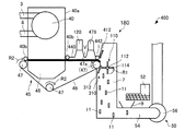
次に、第3実施形態に係るシート製造装置について、図面を参照しながら説明する。図10及び図11は、第3実施形態に係るシート製造装置600を模式的に示す図である。以下、シート製造装置600において、上述したシート製造装置100の例と異なる点について説明し、同様の点については説明を省略する。
3. Third Embodiment 3.1. Sheet Manufacturing Apparatus Next, a sheet manufacturing apparatus according to the third embodiment will be described with reference to the drawings. 10 and 11 are diagrams schematically showing the
図10及び図11に示すように、シート製造装置600は、剥離部310を構成する気流発生部800と、分断部180を構成する吸引部(本実施形態ではブロアー56)を有する点において、上述したシート製造装置100と異なる。
As shown in FIGS. 10 and 11, the
気流発生部800は、気流を発生させ、当該気流により、ウェブVの一部をメッシュベルト46の堆積面から剥離するものである。メッシュベルト46に接触することなくウェブVを堆積面から剥離させることができるため、メッシュベルト46への負荷を抑えることができる。また、メッシュベルト46に気流を吹き付けることにより、メッシュベルト46のメッシュに絡まった解繊物を(固定板312に比して)容易に剥離することができる。気流発生部800は、ブロアー810と、一端がブロアー810に接続された管815と、管815の他端に接続された吹付部820と、を備えている。ブロアー810は、ウェブVを剥離するための気流を発生させる。吹付部820は、開口部821を備えている。そして、ブロアー810によって発生させた気流は、管815を介して吹付部820の開口部821から排出される。
The air
図12は、本実施形態に係る気流発生部の吹付部を模式的に示す図である。図12に示すように、吹付部820の開口部821は、矩形のスリット形状を成している。また、吹付部820は、管815に接続された端部側から開口部821に向けて、気流の方向に交差する方向(開口部821に平行な方向)における断面の開口面積が徐々に小さくなるように形成されている。これにより、開口部821から排出される気流の速度を高めることができる。開口部821の長手方向の長さは、メッシュベルト46の幅(ウェブVの搬送方向に直交する方向の長さ)とほぼ同等である。
FIG. 12: is a figure which shows typically the spraying part of the airflow generation part which concerns on this embodiment. As shown in FIG. 12, the
なお、吹付部820の形態は、上記構成に限定されない。図13及び図14は気流発生部の吹付部の他の形態を模式的に示す一例図である。図13に示すように、吹付部820aは、メッシュベルト46の幅方向に一列に配置された複数のノズル822を備えている。ブロアー810によって発生させた気流は、管815を介して吹付部820aのノズル822から排出される。
The form of the
また、図14に示すように、吹付部820bには、吹付部820bの内部空間および開口部821を、メッシュベルト46の幅方向に区画する複数の区画壁825が設けられている。区画壁825は、例えば、少なくとも一部がフィルターやメッシュ等により形成され、空気を通過可能に構成される。区画壁825により区分けされた空間部分の何れかには、ブロアー810によって発生させた気流を導入するための管815aが設けられている。図14に示す例では、吹付部820bは4つの区画壁825により5つの空間部分に区画され、その内2つの空間部分(両端部から2つ目の各部分)に管815aが設けられている。そして、開口部821は、管815aが設けられた空間部分に対応する開口部821aと、管815aが設けられていない空間部分に対応する開口部821bとに区分けされる。開口部821aからは、管815aから流入した気流が直接的に排出され、開口部821bからは、管815aから流入し区画壁825を通過した気流が排出される。したがって、開口部821bから排出される気流は、開口部821aから排出される気流に比べて、その速度は遅く(強度は弱く)なる。これにより、メッシュベルト46の幅方向(ウェブVの幅方向)に気流の強度差が生じ、ウェブVを、ウェブVの搬送方向に略平行な方向に分断しやすくなる。
Further, as shown in FIG. 14, the
また、図11に示すように、気流発生部800は、堆積面に対して鋭角に、気流を当てるように設定されている。開口部821から排出される気流の向きと、張架ローラー47aに掛かるメッシュベルト46の堆積面とでなす角θaは、0°以上90°未満であり、より好ましくは、0°以上60°以下である。これにより、メッシュベルト46に堆積したウェブVを堆積面から効率良く剥離させることができる。
Further, as shown in FIG. 11, the
また、本実施形態では、気流発生部800によりメッシュベルト46に当てる気流は調湿されている。気流発生部800は調湿部880を備え、調湿部880は、管881を介して、ブロアー810からの気流を吹付部820に送る管815に接続されている。調湿部880は、空気中に水分を放出して、ブロアー810で発生させた気流の湿度を調節することができる。気流の相対湿度は、例えば50%以上70%以下に調湿される。そして、調湿された気流が吹付部820の開口部821から排出され、ウェブVやメッシュベルト46の堆積面に当たる。これにより、ウェブV及びメッシュベルト46の帯電が抑制され、メッシュベルト46からウェブVを容易に剥離させることができる。なお、調湿部880は湿度を増加させる加湿部でもよい。
Further, in the present embodiment, the humidity of the air flow applied to the
吸引部を構成するブロアー56は、ウェブVを吸引することにより分断して細分体11を形成するものである。すなわち、ブロアー56は、剥離されたウェブVを吸引するための気流を発生させる。ブロアー56によって発生される気流の速度は、メッシュベルト46の移動速度(ウェブVの搬送速度)よりも速くなるように設定される。例えば、ブロアー56によって発生される気流の速度は、メッシュベルト46の移動速度よりも10倍以上速くなるように設定される。これにより、ブロアー56によって発生される気流の速度とメッシュベルト46の移動速度との速度差により、ウェブVはウェブVの幅方向(ウェブVの搬送方向と交差する方向)に引き裂かれて細分体11となり、当該細分体11は気流によりブロアー56(堆積部60)側に搬送される。
The
また、分断部180は、ブロアー56に接続された吸引口部900を備えている。吸引口部900は、ブロアー56によって発生した気流により、細分体11を吸引する(吸い込む)ための吸引口921を有している。吸引口921は、ウェブVの搬送方向の下流側端部に対応する位置に設けられている。例えば、吸引口921は、張架ローラー47aおよび後述する回転ローラー49の下流側でこれらのローラー47a,49に対向するように配置されている。吸引口部900は管7に接続され、管7は管54に接続され、管54はブロアー56に接続されている。そして、吸引口921から管7に向かうに従って下方となるように吸引口部900が配置され、管7は管54に向かうに従って下方となるように配置される。細分体11は、ブロアー56が発生させる気流により、吸引口部900から吸引され管7及び管54を介して堆積部60側に搬送される。
Further, the
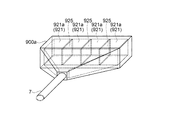
図15は、本実施形態に係る分断部の吸引口部を模式的に示す図である。図15に示すように、吸引口部900は、開口した吸引口921を備えている。吸引口921は、矩形のスリット形状を成している。吸引口部900は、吸引口921から管7に向けて、気流の方向に交差する方向(吸引口921に平行な方向)における断面の開口面積が徐々に小さくなるように形成されている。これにより、管7へ向けて気流の速度を高めることができる。吸引口921は、細分体11を吸い込むことができる程度の大きさを有し、その長手方向の長さはメッシュベルト46の幅とほぼ同等である。
FIG. 15 is a diagram schematically showing the suction port section of the dividing section according to the present embodiment. As shown in FIG. 15, the
なお、吸引口部900の形態は、上記構成に限定されない。図16及び図17は分断部の吸引口部の他の形態を模式的に示す一例図である。図16に示すように、吸引口部900aには、吸引口921を、メッシュベルト46の幅方向に区画する複数の区画壁925が設けられている。区画壁925は、例えば、薄板状の形態を有している。図16に示す例では、3つの区画壁925により4つの吸引口921aが形成されている。気流発生部800が発生させる気流によりメッシュベルト46の堆積面から剥離されたウェブVは、ブロアー56が発生させる気流によって吸引され分断されて細分体11となる。細分体11(ウェブV)は、吸引口921に吸い込まれる際、区画壁925の前端部(前縁部)に接触してウェブVの搬送方向(吸引方向)に略平行な方向に分断され、より小さな体積の細分体11となって、堆積部60側に搬送される。
The form of the
また、図17に示すように、吸引口部900bには、複数の管7aが連結されている。図17に示す例では、3つの管7aが等間隔に設けられている。複数の管7aは合流して一本の管54に接続される。吸引口921から吸引される細分体11(ウェブV)は、各管7aに吸い込まれ、ウェブVの搬送方向(吸引方向)に略平行な方向に分断される。
Further, as shown in FIG. 17, a plurality of
また、図11に示すように、第1ウェブ形成部45は、堆積面を有するメッシュベルト46を支持する支持部としての張架ローラー47aと、メッシュベルト46を間に張架ローラー47aと対向する回転ローラー49と、を有している。回転ローラー49は、吸引口部900の上方に配置された壁部990に設けられたシール部991に当接するように配置されている。これにより、吸引口921付近がほぼ密閉される。そして、メッシュベルト46の堆積面に堆積されたウェブVは、メッシュベルト46を介して張架ローラー47aと回転ローラー49とにより挟持される。また、剥離部310を構成する気流発生部800は、ブロアー810が発生させる気流を、張架ローラー47aよりもウェブVの搬送方向の下流側で、メッシュベルト46の堆積面に当てて、ウェブVを堆積面から剥離する。ウェブVは、張架ローラー47aと回転ローラー49とにより挟持(ニップ)されているため、挟持された位置よりもウェブVの搬送方向下流側の部分のウェブVを剥離することができる。すなわち、ウェブVがメッシュベルト46の堆積面から剥離する位置が安定し、剥離されるウェブVの量(長さ)が略均一となる。そして、分断部180を構成するブロアー56は、剥離されたウェブVを吸引することにより分断し、細分体11が形成される。これにより、堆積部60側に搬送される細分体11の体積の変動を小さくすることができる。
Further, as shown in FIG. 11, the first
また、本実施形態のシート製造装置600では、気流発生部800による風量よりもブロアー56による風量の方が大きくなるように設定される。気流発生部800による気流の流速を計測するための第1流速センサー840と、ブロアー56による気流の流速を計測するための第2流速センサー940と、が設けられている。本実施形態では、吹付部820の内部に第1流速センサー840が配置され、吸引口部900の内部に第2流速センサー940が配置されている。第1流速センサー840及び第2流速センサー940は、例えば、熱線式の流速センサーを適用することができる。なお、熱線式の流速センサーに限定されず、例えば、ベーン式(ヒラム式)の流速計、レーザー光、超音波やマイクロ波を利用した各種流速計を適用することができる。
Further, in the
第1及び第2流速センサー840,940は制御部140に接続されている。そして、制御部140では、第1及び第2流速センサー840,940による計測データに基づいて、吹付部820における気流による風量と吸引口部900における気流による風量とを演算するとともに、両気流の風量を比較し、気流発生部800による風量よりもブロアー56による風量の方が大きくなるように、ブロアー810及びブロアー56を制御する。詳細には、ブロアー810の駆動モーターやブロアー56の駆動モーターを制御する。これにより、吹付部820から排出された気流による解繊物の飛散等を抑制し、吸引口部900に細分体11を吸引させることができる。なお、制御部140の基本的な構成は第1実施形態の構成と同様なので説明を省略する。
The first and second
以上、上記実施形態によれば、以下の効果を得ることができる。 As described above, according to the above embodiment, the following effects can be obtained.
選別部40の開口を通過した第1選別物は、メッシュベルト46上に堆積し、ウェブVが形成される。ウェブVは、張架ローラー47aと回転ローラー49とで挟持された状態でメッシュベルト46により搬送される。そして、張架ローラー47aよりもウェブVの搬送方向下流側で、気流発生部800による気流がメッシュベルト46の堆積面に当てられる。これにより、張架ローラー47aと回転ローラー49とで挟持された位置よりも搬送方向下流側にあるウェブVがメッシュベルト46から剥離する。剥離したウェブVには、ブロアー56による吸引力が働く。これにより、剥離したウェブVは、分断されて細分体11を成し、混合部50(堆積部60)側に搬送される。従って、シート製造装置600では、複数の解繊物が互いに絡み合って大きな塊状となった状態で堆積部60に供給されることを抑制することができ、堆積部60の網の目が目詰まりを起こすことを抑制することができる。そして、シート製造装置600では、密度および厚さの均一性が高いシートSを製造することができる。
The first sorted material that has passed through the opening of the sorting
4. 第4実施形態
4.1. シート製造装置
次に、第4実施形態に係るシート製造装置について、図面を参照しながら説明する。図18は、第4実施形態に係るシート製造装置700を模式的に示す図である。以下、シート製造装置700において、上述したシート製造装置600の例と異なる点について説明し、同様の点については説明を省略する。
4. Fourth Embodiment 4.1. Sheet Manufacturing Apparatus Next, a sheet manufacturing apparatus according to the fourth embodiment will be described with reference to the drawings. FIG. 18 is a diagram schematically showing the
図18に示すように、シート製造装置700は、剥離部310を構成する気流発生部800と、分断部180を構成する吸引部(本実施形態ではブロアー56)および回転体110を備えている。本実施形態では、分断部180が回転体110を備えている点において、上述したシート製造装置600と異なる。
As shown in FIG. 18, the
回転体110は、ウェブVに接触することにより分断して細分体11を形成するための突部114を備えている。本実施形態では、回転体110は、吸引口部900の内部であって、張架ローラー47aの近傍に設けられている。回転体110は、気流発生部800によってメッシュベルト46から剥離されたウェブVに突部114が接触可能な位置であって、メッシュベルト46と接触しない位置に設けられている。回転体110は、その突部114の先端部とメッシュベルト46の堆積面との間に吹付部820から排出される気流が通過可能な程度に、メッシュベルト46から離れて配置されている。
The
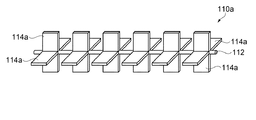
図19は、本実施形態に係る回転体を模式的に示す図である。図19に示すように、回転体110は、基部112と、基部112から突出している板状の突部114と、を有している。図示の例では、4つの突部114が等間隔に設けられている。突部114は、基部112を軸として回転することができる。基部112は、ウェブVの幅方向に延在し、突部114の基部112の延在する方向における長さは、メッシュベルト46の幅とほぼ同等である。なお、突部114の数は特に限定されず、例えば2つであってもよい。
FIG. 19 is a diagram schematically showing the rotating body according to the present embodiment. As shown in FIG. 19, the
なお、回転体110の形態は、上記構成に限定されない。図20及び図21は、回転体の他の形態を模式的に示す一例図である。図20に示すように、回転体110aは、基部112と、基部112から突出している突部114aと、を有している。ここで、突部114aは、基部112の延在する方向に複数配置され、隣接する突部114a間に一定の間隔が設けられている。この回転体110aを用いた場合、ウェブVには、その幅方向において、突部114aに接触する部分と接触しない部分とが出現するため、ウェブVを搬送方向に略平行な方向に分断することができる。
The form of the
また、図21に示すように、回転体110bは、基部112と、基部112から突出している突部114bと、を有している。ここで、突部114bは、基部112の延在する方向に複数配置され、隣接する突部114b同士が回転方向に約90°ずれた位置に配置されている。この回転体110bを用いた場合、ウェブVには、その幅方向において、突部114bに接触する部分と接触しない部分とが出現するため、ウェブVを搬送方向に略平行な方向に分断することができる。
Further, as shown in FIG. 21, the
なお、突部114,114a,114bの形状は板状に限定されない。例えば、ピン形状であってもよい。このようにしても、上記同様の効果を得ることができる。また、本実施形態のシート製造装置700では、気流により剥離したウェブVを分断するため、第1実施形態のシート製造装置100に比べて、回転体110をメッシュベルト46から離れた位置に配置することができる。このため、回転体111の突部114(114a,114b)の先端部を鋭利な刃状とし、ウェブVを分断し易くすることも可能である。
The shapes of the
回転体110の回転方向は、気流発生部800による気流の排出方向等により適宜設定することができる。本実施形態では、気流発生部800による気流は、下方から上方に向けて排出される。従って、回転体110を、気流発生部800による気流の排出方向に倣って矢印R3方向(図18において時計回り)に回転させる。これにより、回転体110の回転方向は気流発生部800による気流の排出方向に逆らうことがないため駆動負荷が低減され、容易にウェブVを分断することができる。
The rotation direction of the
また、本実施形態のシート製造装置700では、回転体110の周速度が、メッシュベルト46の移動速度(ウェブVの搬送速度)よりも速くなるように設定される。例えば、張架ローラー47及び回転体110のそれぞれに、回転速度を検出するためのロータリーエンコーダー等の速度検出センサー(図示せず)を配置する。そして、制御部140では、速度検出センサーによる検出データに基づいて、回転体110の周速度とメッシュベルト46の移動速度とを比較し、回転体110の周速度が、メッシュベルト46の移動速度よりも速くなるように、例えば、回転体110を回転させるための駆動モーターを制御する。例えば、メッシュベルト46の移動速度を毎秒20mm以上100mm以下とした場合、回転体110の周速度はメッシュベルトの移動速度の2倍以上の速さとなるように制御する。これにより、ウェブVをより細かく分断することができる。なお、制御部140の基本的な構成は第1実施形態の構成と同様なので説明を省略する。
Further, in the
以上、上記実施形態によれば、以下の効果を得ることができる。 As described above, according to the above embodiment, the following effects can be obtained.
ブロアー56の風量を抑えた状態でも回転体110によりウェブVを分断して細分体11を形成することができる。従って、ブロアー56に因る消費エネルギーを抑えることができる。
Even when the air volume of the
なお、上記第3及び第4実施形態にかかる気流発生部800では、メッシュベルト46に向けて気流を排出してウェブVをメッシュベルト46から剥離させたが、この構成に限定されない。例えば、気流発生部800において、空気を吸引することによりメッシュベルト46からウェブVを剥離させる構成であってもよい。このようにしても、上記同様の効果を得ることができる。
In the
なお、本発明に係るシート製造装置によって製造されるシートSは、シート状にしたものを主に指す。しかしシート状のものに限定されず、ボード状、ウェブ状であってもよい。本明細書におけるシートは、紙と不織布に分けられる。紙は、パルプや古紙を原料とし薄いシート状に成形した態様などを含み、筆記や印刷を目的とした記録紙や、壁紙、包装紙、色紙、画用紙、ケント紙などを含む。不織布は紙より厚いものや低強度のもので、一般的な不織布、繊維ボード、ティッシュペーパー(清掃用ティッシュペーパー)、キッチンペーパー、クリーナー、フィルター、液体(廃インクや油)吸収材、吸音材、断熱材、緩衝材、マットなどを含む。なお、原料としてはセルロースなどの植物繊維やPET(ポリエチレンテレフタレート)、ポリエステルなどの化学繊維や羊毛、絹などの動物繊維であってもよい。 In addition, the sheet S manufactured by the sheet manufacturing apparatus according to the present invention mainly indicates a sheet-shaped sheet. However, the shape is not limited to the sheet shape, and may be a board shape or a web shape. The sheet in this specification is divided into paper and non-woven fabric. The paper includes an embodiment in which a thin sheet is formed from pulp or waste paper as a raw material, and includes recording paper for writing and printing, wallpaper, wrapping paper, colored paper, drawing paper, Kent paper, and the like. Non-woven fabrics are thicker than paper and have low strength. Common non-woven fabrics, fiber boards, tissue paper (tissue paper for cleaning), kitchen paper, cleaners, filters, liquid (waste ink and oil) absorbers, sound absorbing materials, Includes insulation, cushioning, mats, etc. The raw materials may be plant fibers such as cellulose, PET (polyethylene terephthalate), chemical fibers such as polyester, and animal fibers such as wool and silk.
本発明は、本願に記載の特徴や効果を有する範囲で一部の構成を省略したり、各実施形態や変形例を組み合わせたりしてもよい。なお、製造部102は、シートを製造できる範囲において、一部の構成を省略したり、他の構成を追加したり、公知の構成と置き換えてもよい。
The present invention may omit some of the configurations or combine the embodiments and modifications within the scope of the features and effects described in the present application. Note that the
本発明は、実施の形態で説明した構成と実質的に同一の構成(例えば、機能、方法及び結果が同一の構成、あるいは目的及び効果が同一の構成)を含む。また、本発明は、実施の形態で説明した構成の本質的でない部分を置き換えた構成を含む。また、本発明は、実施の形態で説明した構成と同一の作用効果を奏する構成又は同一の目的を達成することができる構成を含む。また、本発明は、実施の形態で説明した構成に公知技術を付加した構成を含む。 The present invention includes configurations substantially the same as the configurations described in the embodiments (for example, configurations having the same function, method and result, or configurations having the same object and effect). Further, the invention includes configurations in which non-essential parts of the configurations described in the embodiments are replaced. Further, the invention includes a configuration that achieves the same effect as the configuration described in the embodiment or a configuration that can achieve the same object. Further, the invention includes configurations in which known techniques are added to the configurations described in the embodiments.
1…ホッパー、2,3,4,5,7,7a,8…管、9…ホッパー、10…供給部、11…細分体、12…粗砕部、14…粗砕刃、20…解繊部、22…導入口、24…排出口、30…分級部、31…導入口、32…円筒部、33…逆円錐部、34…下部排出口、35…上部排出口、36…受け部、40…選別部、40a…ハウジング部、40b…パイルシール、42…導入口、44…排出口、45…第1ウェブ形成部、46…メッシュベルト、47,47a…張架ローラー、48…吸引部、49…回転ローラー、50…混合部、52…添加物供給部、54…管、56…ブロアー、60…堆積部、62…導入口、70…第2ウェブ形成部、72…メッシュベルト、74…張架ローラー、76…サクション機構、78…調湿部、80…シート形成部、82…第1結着部、84…第2結着部、86…加熱ローラー、90…切断部、92…第1切断部、94…第2切断部、96…排出部、100,200,300,400,500,600,700,800…シート製造装置、102…製造部、110,110a,110b…回転体、112…基部、114,114a,114b…突部、120…検出部、140…制御部、141…操作部、142…出力部、143…記憶部、144…記憶媒体、145…処理部、180…分断部、310…剥離部、312…固定板、313…主面、314…端、412…固定板、440…カバー部、442…パイルシール、478…調湿部、512…気流発生部、810…ブロアー、815,815a…管、820,820a,820b…吹付部、821,821a,821b…開口部、822…ノズル、825…区画壁、840…第1流速センサー、880…調湿部、900,900a,900b…吸引口部、921…,921a…吸引口、925…区画壁、940…第2流速センサー、A…気流、S…シート、V,W…ウェブ。
DESCRIPTION OF
Claims (15)
前記解繊部により解繊された前記解繊物を選別する選別部と、
前記選別部により選別された前記解繊物が堆積したウェブを形成するウェブ形成部と、
前記ウェブ形成部により形成された前記ウェブを分断して細分体を形成する分断部と、
前記細分体を構成する前記解繊物を堆積させる堆積部と、
前記堆積部により堆積された前記解繊物を用いてシートを成形する形成部と、を有し、
前記ウェブ形成部は、
前記ウェブが堆積される堆積面と、
前記堆積面に堆積された前記ウェブを、前記堆積面から剥離するための剥離部と、を有し、
前記分断部は、前記ウェブに接触することにより分断して細分体を形成するための突部を備えた回転体と、を有し、
前記ウェブ形成部は、前記堆積面を有するベルトと、前記ベルトが張架される少なくとも2つのローラーを有し、
前記剥離部は、固定板を有し、
前記固定板は、前記ローラーのうち前記回転体側に位置するローラーに対向し前記ベルトに接することを特徴とするシート製造装置。 A defibration unit for defibrating a raw material containing fibers into a defibrated material,
A selection unit for selecting the defibrated material defibrated by the defibration unit,
A web forming unit that forms a web in which the defibrated material sorted by the sorting unit is deposited,
A dividing portion that divides the web formed by the web forming portion to form a subdivided body,
A deposition unit that deposits the defibrated material that constitutes the subdivided body,
A forming unit for forming a sheet using the defibrated material accumulated by the accumulation unit ,
The web forming unit,
A deposition surface on which the web is deposited,
A stripping portion for stripping the web deposited on the deposition surface from the deposition surface,
The dividing section includes a rotating body having a protrusion for forming a subdivided body by being divided by contacting the web,
The web forming unit includes a belt having the deposition surface and at least two rollers around which the belt is stretched,
The peeling section has a fixing plate,
The fixing plate is a sheet manufacturing apparatus, characterized by contact with the belt facing the roller located at the rotor side of the roller.
前記解繊部により解繊された前記解繊物を選別する選別部と、
前記選別部により選別された前記解繊物が堆積したウェブを形成するウェブ形成部と、
前記ウェブ形成部により形成された前記ウェブを分断して細分体を形成する分断部と、
前記細分体を構成する前記解繊物を堆積させる堆積部と、
前記堆積部により堆積された前記解繊物を用いてシートを成形する形成部と、を有し、
前記ウェブ形成部は、
前記ウェブが堆積される堆積面と、
前記堆積面に堆積された前記ウェブを、前記堆積面から剥離するための剥離部と、を有し、
前記分断部は、前記ウェブに接触することにより分断して細分体を形成するための突部を備えた回転体と、を有し、
前記剥離部は、前記回転体の近傍で前記ウェブが前記ベルトから離れる方向の気流を発生させる気流発生部を有することを特徴とするシート製造装置。 A defibration unit for defibrating a raw material containing fibers into a defibrated material,
A selection unit for selecting the defibrated material defibrated by the defibration unit,
A web forming unit that forms a web in which the defibrated material sorted by the sorting unit is deposited,
A dividing portion that divides the web formed by the web forming portion to form a subdivided body,
A deposition unit that deposits the defibrated material that constitutes the subdivided body,
A forming unit for forming a sheet using the defibrated material accumulated by the accumulation unit,
The web forming unit,
A deposition surface on which the web is deposited,
A stripping portion for stripping the web deposited on the deposition surface from the deposition surface,
The dividing section includes a rotating body having a protrusion for forming a subdivided body by being divided by contacting the web,
The peeling portion, the rotating body features and be Resid over preparative production apparatus further comprising a flow generator unit for the web to generate a direction of air flow away from the belt in the vicinity of.
前記解繊部により解繊された前記解繊物を選別する選別部と、
前記選別部により選別された前記解繊物が堆積したウェブを形成するウェブ形成部と、
前記ウェブ形成部により形成された前記ウェブを分断して細分体を形成する分断部と、
前記細分体を構成する前記解繊物を堆積させる堆積部と、
前記堆積部により堆積された前記解繊物を用いてシートを成形する形成部と、を有し、
前記ウェブ形成部は、
前記ウェブが堆積される堆積面と、
前記堆積面に堆積された前記ウェブを、前記堆積面から剥離するための剥離部と、を有し、
前記分断部は、前記ウェブに接触することにより分断して細分体を形成するための突部を備えた回転体と、を有し、
前記ウェブ形成部は、前記堆積面を有するベルトを有し、
前記ベルトの移動速度に応じて、前記回転体の回転速度を制御する制御部を有することを特徴とする記載のシート製造装置。 A defibration unit for defibrating a raw material containing fibers into a defibrated material,
A selection unit for selecting the defibrated material defibrated by the defibration unit,
A web forming unit that forms a web in which the defibrated material sorted by the sorting unit is deposited,
A dividing portion that divides the web formed by the web forming portion to form a subdivided body,
A deposition unit that deposits the defibrated material that constitutes the subdivided body,
A forming unit for forming a sheet using the defibrated material deposited by the depositing unit,
The web forming unit,
A deposition surface on which the web is deposited,
A stripping portion for stripping the web deposited on the deposition surface from the deposition surface,
The dividing section includes a rotating body having a protrusion for forming a subdivided body by dividing by contacting the web,
The web forming unit has a belt having the deposition surface,
According to the moving speed of the belt, sheet manufacturing apparatus that Symbol mounting to characterized in that it has a control unit for controlling the rotational speed of the rotating body.
前記制御部は、前記検出部により検出された前記ウェブの厚さに基づいて、前記ベルトの移動速度を制御することを特徴とする請求項3に記載のシート製造装置。 A detection unit for detecting the thickness of the web,
The sheet manufacturing apparatus according to claim 3 , wherein the control unit controls the moving speed of the belt based on the thickness of the web detected by the detection unit.
前記解繊部により解繊された前記解繊物を選別する選別部と、
前記選別部により選別された前記解繊物が堆積したウェブを形成するウェブ形成部と、
前記ウェブ形成部により形成された前記ウェブを分断して細分体を形成する分断部と、
前記細分体を構成する前記解繊物を堆積させる堆積部と、
前記堆積部により堆積された前記解繊物を用いてシートを成形する形成部と、を有し、
前記ウェブ形成部は、
前記ウェブが堆積される堆積面と、
前記堆積面に堆積された前記ウェブを、前記堆積面から剥離するための剥離部と、を有し、
前記分断部は、前記ウェブに接触することにより分断して細分体を形成するための突部を備えた回転体と、を有し、
前記ウェブの厚さを検出する検出部と、
前記検出部により検出された前記ウェブの厚さに基づいて、前記回転体の回転速度を制御する制御部と、を有することを特徴とするシート製造装置。 A defibration unit for defibrating a raw material containing fibers into a defibrated material,
A selection unit for selecting the defibrated material defibrated by the defibration unit,
A web forming unit that forms a web in which the defibrated material sorted by the sorting unit is deposited,
A dividing portion that divides the web formed by the web forming portion to form a subdivided body,
A deposition unit that deposits the defibrated material that constitutes the subdivided body,
A forming unit for forming a sheet using the defibrated material accumulated by the accumulation unit,
The web forming unit,
A deposition surface on which the web is deposited,
A stripping portion for stripping the web deposited on the deposition surface from the deposition surface,
The dividing section includes a rotating body having a protrusion for forming a subdivided body by being divided by contacting the web,
A detection unit for detecting the thickness of the web,
On the basis of the thickness of said detected web by the detecting unit, wherein the to Resid over preparative manufacturing apparatus that has a control unit for controlling the rotational speed of the rotating body.
前記解繊部により解繊された前記解繊物を選別する選別部と、
前記選別部により選別された前記解繊物が堆積したウェブを形成するウェブ形成部と、
前記ウェブ形成部により形成された前記ウェブを分断して細分体を形成する分断部と、
前記細分体を構成する前記解繊物を堆積させる堆積部と、
前記堆積部により堆積された前記解繊物を用いてシートを成形する形成部と、を有し、
前記ウェブ形成部は、
前記ウェブが堆積される堆積面と、
前記堆積面に堆積された前記ウェブを、前記堆積面から剥離するための剥離部と、を有し、
前記分断部は、前記ウェブに接触することにより分断して細分体を形成するための突部を備えた回転体と、を有し、
前記剥離部は、気流発生部を有し、
前記気流発生部は、前記堆積面に対して鋭角に発生させる気流により、前記ウェブを前記堆積面から剥離することを特徴とするシート製造装置。 A defibration unit for defibrating a raw material containing fibers into a defibrated material,
A selection unit for selecting the defibrated material defibrated by the defibration unit,
A web forming unit that forms a web in which the defibrated material sorted by the sorting unit is deposited,
A dividing portion that divides the web formed by the web forming portion to form a subdivided body,
A deposition unit that deposits the defibrated material that constitutes the subdivided body,
A forming unit for forming a sheet using the defibrated material accumulated by the accumulation unit,
The web forming unit,
A deposition surface on which the web is deposited,
A stripping portion for stripping the web deposited on the deposition surface from the deposition surface,
The dividing section includes a rotating body having a protrusion for forming a subdivided body by being divided by contacting the web,
The peeling section has an airflow generating section,
The sheet manufacturing apparatus , wherein the air flow generation unit separates the web from the deposition surface by an air flow generated at an acute angle with respect to the deposition surface.
前記ベルトを間に前記支持部と対向する回転ローラーと、を有し、
前記堆積面に堆積されたウェブは、前記支持部と前記回転ローラーとにより挟持され、
前記剥離部は、前記支持部よりも前記ウェブの搬送方向の下流側で、前記気流発生部が発生させる気流を前記堆積面に当てて、前記ウェブを前記堆積面から剥離し、
前記分断部は、前記剥離部により剥離されたウェブを、前記吸引部により吸引することを特徴とする請求項9に記載のシート製造装置。 The web forming unit, a belt having the deposition surface, a support unit for supporting the belt,
A rotating roller that faces the support portion between the belt,
The web deposited on the deposition surface is sandwiched by the support portion and the rotating roller,
The peeling portion, on the downstream side in the transport direction of the web with respect to the support portion, the airflow generated by the airflow generating portion is applied to the deposition surface to peel the web from the deposition surface,
The sheet manufacturing apparatus according to claim 9 , wherein the dividing unit sucks the web peeled by the peeling unit by the suction unit.
前記ウェブが堆積されるメッシュベルトと、
前記ウェブが堆積される前記メッシュベルトの面とは反対側の面から、前記選別部により選別された前記解繊物を吸引する吸引部と、
を有することを特徴とする請求項1〜12の何れか1項に記載のシート製造装置。 The web forming unit,
A mesh belt on which the web is deposited,
From a surface opposite to the surface of the mesh belt on which the web is deposited, a suction unit that sucks the defibrated material selected by the selection unit,
The sheet manufacturing apparatus according to any one of claims 1 to 12 , further comprising:
前記解繊部により解繊された前記解繊物を選別する選別部と、A selection unit for selecting the defibrated material defibrated by the defibration unit,
前記選別部により選別された前記解繊物が堆積したウェブを形成するウェブ形成部と、A web forming unit that forms a web in which the defibrated material sorted by the sorting unit is deposited,
前記ウェブ形成部により形成された前記ウェブを分断して細分体を形成する分断部と、A dividing portion that divides the web formed by the web forming portion to form a subdivided body,
前記細分体を構成する前記解繊物を堆積させる堆積部と、A deposition unit that deposits the defibrated material that constitutes the subdivided body,
前記堆積部により堆積された前記解繊物を用いてシートを成形する形成部と、A forming unit that forms a sheet using the defibrated material accumulated by the accumulation unit,
前記細分体が供給され前記堆積部に接続されている管と、A tube supplied with the subdivided body and connected to the deposition section;
前記管から前記細分体を前記堆積部に搬送するブロアーと、A blower that conveys the subdivided body from the tube to the deposition unit,
を有し、Have
前記分断部は、前記ウェブに接触することにより分断して細分体を形成するための突部を備えた回転体であることを特徴とするシート製造装置。The sheet manufacturing apparatus, wherein the dividing section is a rotating body including a protrusion for dividing the web by contacting the web to form a subdivided body.
前記回転体の回転方向とローラーの回転方向とは、互いに反対であることを特徴とする請求項14に記載に記載のシート製造装置。The sheet manufacturing apparatus according to claim 14, wherein the rotating direction of the rotating body and the rotating direction of the roller are opposite to each other.
Priority Applications (5)
| Application Number | Priority Date | Filing Date | Title |
|---|---|---|---|
| US15/071,356 US9771685B2 (en) | 2015-03-18 | 2016-03-16 | Sheet manufacturing apparatus and sheet manufacturing method |
| EP16160782.5A EP3070202B1 (en) | 2015-03-18 | 2016-03-16 | Sheet manufacturing apparatus and sheet manufacturing method |
| EP17196012.3A EP3299517B1 (en) | 2015-03-18 | 2016-03-16 | Sheet manufacturing apparatus and sheet manufacturing method |
| CN201610152941.6A CN105986496B (en) | 2015-03-18 | 2016-03-17 | Sheet manufacturing apparatus and sheet manufacturing method |
| US15/686,237 US10081913B2 (en) | 2015-03-18 | 2017-08-25 | Sheet manufacturing apparatus |
Applications Claiming Priority (2)
| Application Number | Priority Date | Filing Date | Title |
|---|---|---|---|
| JP2015054415 | 2015-03-18 | ||
| JP2015054415 | 2015-03-18 |
Publications (3)
| Publication Number | Publication Date |
|---|---|
| JP2016175403A JP2016175403A (en) | 2016-10-06 |
| JP2016175403A5 JP2016175403A5 (en) | 2019-02-21 |
| JP6733209B2 true JP6733209B2 (en) | 2020-07-29 |
Family
ID=57069605
Family Applications (1)
| Application Number | Title | Priority Date | Filing Date |
|---|---|---|---|
| JP2016028632A Active JP6733209B2 (en) | 2015-03-18 | 2016-02-18 | Sheet manufacturing equipment |
Country Status (1)
| Country | Link |
|---|---|
| JP (1) | JP6733209B2 (en) |
Families Citing this family (9)
| Publication number | Priority date | Publication date | Assignee | Title |
|---|---|---|---|---|
| US11015273B2 (en) | 2016-11-29 | 2021-05-25 | Seiko Epson Corporation | Web forming device and sheet manufacturing apparatus |
| JP2018090931A (en) * | 2016-12-06 | 2018-06-14 | セイコーエプソン株式会社 | Sheet production apparatus, sheet production method, pulp-derived product manufacturing apparatus and pulp-derived product manufacturing method |
| JP6946693B2 (en) * | 2017-03-29 | 2021-10-06 | セイコーエプソン株式会社 | Seat manufacturing system |
| JP6900731B2 (en) * | 2017-03-29 | 2021-07-07 | セイコーエプソン株式会社 | Seat manufacturing system |
| JP6943006B2 (en) * | 2017-04-24 | 2021-09-29 | セイコーエプソン株式会社 | Processing equipment, sheet manufacturing equipment, processing method and sheet manufacturing method |
| JP6943007B2 (en) * | 2017-04-24 | 2021-09-29 | セイコーエプソン株式会社 | Processing equipment, sheet manufacturing equipment, processing method and sheet manufacturing method |
| JP7003792B2 (en) * | 2018-03-28 | 2022-02-10 | セイコーエプソン株式会社 | Web forming equipment, web forming method and sheet manufacturing equipment |
| JP7119661B2 (en) * | 2018-07-06 | 2022-08-17 | セイコーエプソン株式会社 | Web forming apparatus, web processing apparatus, fiber raw material recycling apparatus, and web forming method |
| JP2020097180A (en) * | 2018-12-18 | 2020-06-25 | セイコーエプソン株式会社 | Processing apparatus, molded body and processing method |
Family Cites Families (7)
| Publication number | Priority date | Publication date | Assignee | Title |
|---|---|---|---|---|
| JPS56101962A (en) * | 1979-12-21 | 1981-08-14 | Kimberly Clark Co | Method and apparatus for producing dry web with high properties and uniformity by air laying system |
| US4475271A (en) * | 1982-04-29 | 1984-10-09 | Chicopee | Process and apparatus for producing uniform fibrous web at high rate of speed |
| FR2540895B1 (en) * | 1983-02-15 | 1986-01-24 | Beghin Say Sa | PROCESS FOR SHORTENING TEXTILE FIBERS, IN PARTICULAR WHITE COTTON WASTE, FIBERS OBTAINED BY THIS PROCESS AND APPLICATION THEREOF AS ABSORBENT MATTRESS |
| US8632768B2 (en) * | 2008-05-30 | 2014-01-21 | University Of Louisville Research Foundation, Inc. | Human facilitating cells |
| JP5720255B2 (en) * | 2011-01-12 | 2015-05-20 | セイコーエプソン株式会社 | Paper recycling apparatus and paper recycling method |
| KR101319183B1 (en) * | 2011-08-02 | 2013-10-18 | 도레이첨단소재 주식회사 | Spunbond nonwoven fabric having an improved property and preparing method thereof |
| JP6213284B2 (en) * | 2013-03-27 | 2017-10-18 | セイコーエプソン株式会社 | Sheet manufacturing equipment |
-
2016
- 2016-02-18 JP JP2016028632A patent/JP6733209B2/en active Active
Also Published As
| Publication number | Publication date |
|---|---|
| JP2016175403A (en) | 2016-10-06 |
Similar Documents
| Publication | Publication Date | Title |
|---|---|---|
| JP6733209B2 (en) | Sheet manufacturing equipment | |
| EP3070202B1 (en) | Sheet manufacturing apparatus and sheet manufacturing method | |
| JP6604428B2 (en) | Sheet manufacturing equipment | |
| JP6617405B2 (en) | Sheet manufacturing apparatus and sheet manufacturing method | |
| JP6511839B2 (en) | Sheet manufacturing apparatus and sheet manufacturing method | |
| CN104074080A (en) | Sheet manufacturing apparatus | |
| JP6677162B2 (en) | Sheet manufacturing apparatus and sheet manufacturing method | |
| JP6798486B2 (en) | Sheet manufacturing equipment and sheet manufacturing method | |
| JP6798485B2 (en) | Sheet manufacturing equipment | |
| JP6531381B2 (en) | Sheet manufacturing apparatus and sheet manufacturing method | |
| JP2016124211A (en) | Apparatus and method for producing sheet | |
| JP2017013264A (en) | Sheet production device | |
| JP6954328B2 (en) | Sheet manufacturing equipment | |
| JP6690656B2 (en) | Sheet manufacturing equipment | |
| JP6519337B2 (en) | Sheet manufacturing equipment | |
| JP2019218667A (en) | Web forming apparatus and sheet manufacturing apparatus | |
| JP6365837B2 (en) | Sheet manufacturing equipment | |
| JP6804837B2 (en) | Sheet manufacturing equipment | |
| JP7028173B2 (en) | Sheet manufacturing equipment | |
| JP6551676B2 (en) | Sheet manufacturing apparatus and method for detecting thickness of cut sheet material in sheet manufacturing apparatus | |
| JP2023064869A (en) | Control method of sheet production apparatus, and sheet production apparatus | |
| JP6620532B2 (en) | Sheet manufacturing equipment | |
| JP6634793B2 (en) | Sheet manufacturing equipment | |
| JP2016129995A (en) | Sheet production apparatus and sheet production method |
Legal Events
| Date | Code | Title | Description |
|---|---|---|---|
| RD05 | Notification of revocation of power of attorney |
Free format text: JAPANESE INTERMEDIATE CODE: A7425 Effective date: 20180905 |
|
| RD03 | Notification of appointment of power of attorney |
Free format text: JAPANESE INTERMEDIATE CODE: A7423 Effective date: 20181115 |
|
| A521 | Written amendment |
Free format text: JAPANESE INTERMEDIATE CODE: A523 Effective date: 20190110 |
|
| A621 | Written request for application examination |
Free format text: JAPANESE INTERMEDIATE CODE: A621 Effective date: 20190110 |
|
| A977 | Report on retrieval |
Free format text: JAPANESE INTERMEDIATE CODE: A971007 Effective date: 20191114 |
|
| A131 | Notification of reasons for refusal |
Free format text: JAPANESE INTERMEDIATE CODE: A131 Effective date: 20191126 |
|
| A521 | Written amendment |
Free format text: JAPANESE INTERMEDIATE CODE: A523 Effective date: 20200116 |
|
| TRDD | Decision of grant or rejection written | ||
| A01 | Written decision to grant a patent or to grant a registration (utility model) |
Free format text: JAPANESE INTERMEDIATE CODE: A01 Effective date: 20200609 |
|
| A61 | First payment of annual fees (during grant procedure) |
Free format text: JAPANESE INTERMEDIATE CODE: A61 Effective date: 20200622 |
|
| R150 | Certificate of patent or registration of utility model |
Ref document number: 6733209 Country of ref document: JP Free format text: JAPANESE INTERMEDIATE CODE: R150 |