JP6730209B2 - Induction cooker - Google Patents
Induction cooker Download PDFInfo
- Publication number
- JP6730209B2 JP6730209B2 JP2017040147A JP2017040147A JP6730209B2 JP 6730209 B2 JP6730209 B2 JP 6730209B2 JP 2017040147 A JP2017040147 A JP 2017040147A JP 2017040147 A JP2017040147 A JP 2017040147A JP 6730209 B2 JP6730209 B2 JP 6730209B2
- Authority
- JP
- Japan
- Prior art keywords
- substrate
- heating coil
- air
- heating
- main body
- Prior art date
- Legal status (The legal status is an assumption and is not a legal conclusion. Google has not performed a legal analysis and makes no representation as to the accuracy of the status listed.)
- Active
Links
Images


Description
本発明は、誘導加熱調理器に関する。 The present invention relates to an induction heating cooker.
誘導加熱調理器は、加熱コイルに高周波電流を流して発生した磁力線が、金属製鍋の鍋底を通過するときに鍋底に生じる渦電流によるジュール加熱を利用して、加熱調理を行う調理器である。加熱調理時には鍋底だけでなく、加熱コイルや制御基板等も発熱するため、ファン装置を用いて加熱コイルや制御基板を送風冷却している。 An induction heating cooker is a cooker that uses Joule heating due to eddy currents generated in the bottom of a metal pot when magnetic field lines generated by passing a high-frequency current through the heating coil pass through the bottom of the pot. .. During heating and cooking, not only the bottom of the pan, but also the heating coil, the control board, and the like generate heat. Therefore, a fan device is used to blow and cool the heating coil and the control board.
また、システムキッチンに組み込まれる誘導加熱調理器では、トッププレート上での加熱調理に加え、電熱ヒータなどの熱源を備えたグリル庫を利用して魚焼きなどの調理を行うことができるものが主流となっている。 In addition, in the induction heating cooker installed in the system kitchen, in addition to cooking on the top plate, those that can cook such as grilled fish using a grill with a heat source such as an electric heater are mainstream. Has become.
このような従来の誘導加熱調理器では、冷却対象となる主要部品は複数の加熱コイルと制御基板であり、構造上、加熱コイルは本体上方のトッププレート近傍、制御基板はグリル部側方の余剰空間に収納される構成が一般的である。 In such a conventional induction heating cooker, the main parts to be cooled are a plurality of heating coils and a control board. Due to the structure, the heating coils are near the top plate above the main body, and the control board is a surplus on the side of the grill. It is generally configured to be stored in a space.
なお、システムキッチンに配置される本体の吸気口および排気口は、特許文献1に示すように「本体外郭の外面前部もしくは底部又は双方に設けられた吸気口と、吸気口を通して本体外郭の外側の空気を吸気し本体内部の発熱部位に送風し強制冷却するファンと、本体外郭後方の上部に設けられた冷却風の出口となる排気口とを備えた」構成となっており、加熱中の調理鍋での沸騰や突沸によるふきこぼれや鍋の水蒸気を、本体の内部に流入し難い構成が採られている。 In addition, the intake port and the exhaust port of the main body arranged in the system kitchen are, as shown in Patent Document 1, "the intake port provided on the outer surface front part or the bottom part of the main body outer shell or both, and the outside of the main body outer shell through the intake port. It is equipped with a fan that inhales air and blows it to the heat generation part inside the main body to forcibly cool it, and an exhaust port that is an outlet for cooling air provided in the upper rear part of the main body's configuration. The structure is such that the spillage due to boiling or bumping in the cooking pot and the steam in the pot do not easily flow into the main body.
また、誘導加熱調理器をシステムキッチン枠に収納する場合、トッププレート外周端でフランジ部を構成して本体を保持する構造となっており、トッププレート上で調理鍋の加熱中にふきこぼれた液体(水)が、システムキッチン枠とトッププレート(フランジ部)隙間から入りにくいように、トッププレート外周側にパッキンが設けられる。 When the induction cooker is stored in the system kitchen frame, the outer edge of the top plate forms a flange to hold the main body, and the liquid spilled over the top plate during heating of the cooking pot ( Packing is provided on the outer peripheral side of the top plate so that water cannot easily enter through the gap between the system kitchen frame and the top plate (flange portion).
或いは、万一誤って、トッププレートに亀裂や破損が生じた状態で加熱動作した場合であっても、ふきこぼれた液体が制御基板の充電部(回路パターンの露出部)への浸入を抑制する構造が採られてきた。 Alternatively, even if the heating operation is accidentally performed with the top plate cracked or damaged, a structure that suppresses the spilled liquid from entering the charging part (exposed part of the circuit pattern) of the control board. Has been taken.
また、上記の液体侵入などによる故障に限らず、使用環境や使用頻度、使用鍋の種類などにより予期されない故障などが生じる場合がある。その際、故障や修理時のサービスでは、トッププレートを外し、更に加熱コイルの下方に配置される制御基板の部品交換など行う必要がある。このサービス性においては、センサなどの部品の取付け・取外し作業が容易であるほど、修理・交換が速やかにできるため、アクセスしやすい位置にコネクタなどが設けられていることが望ましい。 Further, not only the failure due to the above liquid intrusion, but an unexpected failure may occur depending on the use environment, the use frequency, the type of pot used, and the like. At that time, in the case of service at the time of failure or repair, it is necessary to remove the top plate and further replace parts of the control board arranged below the heating coil. In terms of serviceability, it is desirable that the connector or the like is provided at a position where it can be easily accessed because the easier the work of mounting and removing the parts such as the sensor, the quicker the repair/replacement.
一方、国内における大部分のシステムキッチン枠は、寸法が規定されているため、誘導加熱調理器の外形最大寸法もおおよそ定まっており、加熱コイルや制御基板の冷却には限られた空間内で最適な風路を構成する必要がある。 On the other hand, since most system kitchen frames in Japan have specified dimensions, the maximum external dimensions of induction heating cookers are also roughly determined, which is ideal for cooling heating coils and control boards within a limited space. It is necessary to construct a simple air path.
加熱コイルで効率よく調理鍋を誘導加熱させるには、加熱コイルに給電するインバータ回路の電子部品やコネクタを最適にレイアウトすることが重要である。最適なレイアウトとは、一般に、部品間の距離が短く(高集積)、電源など他電子部品による影響を受け難い(低ノイズ)、理想的な回路パターンで部品配置することである。特許文献2には「加熱部(加熱コイル)支持板の下方に、加熱部を駆動及び制御する制御部を有する制御基板があり、ファンモータが制御基板上の部品の発熱を冷却し、それらは同じく加熱部支持板の下方に設けられた上方に開口を設けた箱状の外郭の中に収納する」構成となっており、複数のインバータ回路を一つの制御基板上に一面で構成し、例えば制御基板間や制御基板上の電子部品を跨ぐ配線(ジャンパー線など)が無いように部品配置している。
In order to efficiently heat the cooking pot with the heating coil, it is important to optimally lay out the electronic components and connectors of the inverter circuit that feeds the heating coil. The optimum layout generally means that the distance between the components is short (high integration), the components are hardly affected by other electronic components such as a power supply (low noise), and the components are arranged in an ideal circuit pattern. In
特許文献1の誘導加熱調理器では、グリル庫側方に複数の制御基板を上下に積層して収納しており、制御基板間を繋ぐ複数の配線を有した回路構成となるため、回路ノイズが生じ易く加熱効率が悪化する。さらに、加熱コイルや制御基板を冷却するファン装置を狭い空間に収納し、ファン装置の吸排気部の近傍に、様々な部材を近接して配置している。このため、部材の配置により生じた風速分布による吸気流れの乱れや通風抵抗の増大により、ファン装置の送風性能が悪化し、部品冷却性能の低下や、ファン騒音の増加要因となっている。また、積層した基板構成はサービス性が良好で無く、例えば最下層の基板交換の場合、大部分の部品を外す必要があり、膨大な作業時間と手間を要する。 In the induction heating cooker of Patent Document 1, a plurality of control boards are vertically stacked and housed on the side of the grill cabinet, and a circuit configuration having a plurality of wirings connecting the control boards is provided. It easily occurs and heating efficiency deteriorates. Furthermore, a fan device that cools the heating coil and the control board is housed in a narrow space, and various members are arranged in the vicinity of the intake/exhaust portion of the fan device. Therefore, the turbulence of the intake air flow due to the distribution of the wind speed generated by the arrangement of the members and the increase of the ventilation resistance deteriorate the ventilation performance of the fan device, which causes the cooling performance of the components to deteriorate and the fan noise to increase. Further, the laminated board structure does not have good serviceability, and for example, in the case of replacing the board in the lowermost layer, it is necessary to remove most of the components, which requires enormous work time and labor.
一方、最も主流の構成であるグリル庫を有する誘導加熱調理器の場合、特許文献2のように、一面に並べた複数のファン装置と制御基板を、グリル庫とトッププレートの間に収納することは基板実装容積が小さくなり困難である。一般的なシステムキッチンでは、グリル庫とトッププレートの隙間は60mm程度しかなく、グリル庫は本体幅の約半分以上の容積となっている。このため、制御基板を略同一面に配置して本体に収納しようとする場合、グリル庫から加熱コイルまでの高さ方向の隙間は20〜30mm程度となり、部品実装容積が従来(例えば特許文献1)よりも減少する。ここで、制御基板には高発熱する電子部品を設置して放熱するヒートシンクを実装しており、グリル庫の側方に積層して収納する制御基板では高さ40〜50mm程度のヒートシンクを用いている。高発熱する電子部品の冷却は、ヒートシンクの容積とヒートシンクに流す風量で定まるので、ヒートシンク容積を小さくすれば、大風量(フィン間風速の向上)或いは微細なフィン形状(フィン放熱面積)が必要となり、圧力が高い大型のファン装置が必要となる。
On the other hand, in the case of an induction heating cooker having a grill cabinet, which is the most mainstream configuration, a plurality of fan devices and a control board arranged side by side are housed between the grill cabinet and the top plate as in
さらに、加熱コイルの下方に制御基板を配置した場合、従来に比べて制御基板とトッププレートの位置関係が近くなる。このため、特許文献1のような制御基板を片側に集中して積層した状態に比べて、液体浸入により制御基板と液体が接触する可能性が高くなる。つまり、トッププレートの排気口と制御基板との距離、トッププレート外周端と制御基板との距離が格段に近くなる。さらに、トッププレートの亀裂や破損時に対し、トッププレート全面で液体浸入の可能性が生じることとなる。 Further, when the control board is arranged below the heating coil, the positional relationship between the control board and the top plate becomes closer than in the conventional case. Therefore, compared to the state in which the control substrate is concentrated and laminated on one side as in Patent Document 1, the possibility that the control substrate and the liquid come into contact with each other due to the liquid intrusion becomes higher. In other words, the distance between the exhaust port of the top plate and the control board and the distance between the outer edge of the top plate and the control board become much shorter. Furthermore, when the top plate is cracked or damaged, liquid may enter the entire surface of the top plate.
そこで、本発明は、電子部品を最適配置できるように、制御基板を加熱コイルの下方に配置し、高効率で駆動する回路パターンを実装した制御基板レイアウトにするとともに、液体の浸入防止構造を備え、通風抵抗を抑えた送風路による低騒音運転と故障時のサービス性を成立した空冷構造を有する誘導加熱調理器を提供することを課題とする。 Therefore, according to the present invention, the control board is arranged below the heating coil so that the electronic parts can be optimally arranged, and the control board layout is provided with a circuit pattern that drives with high efficiency, and a liquid intrusion prevention structure is provided. An object of the present invention is to provide an induction heating cooker having an air-cooling structure that realizes low noise operation by a ventilation path with suppressed ventilation resistance and serviceability in case of failure.
前記課題を解決するために、本発明に係る誘導加熱調理器は、本体と、該本体の上面に設置するトッププレートと、該トッププレートの下方に設ける加熱コイルと、前記加熱コイルよりも下方に配置されるとともに、前記加熱コイルに高周波電流を供給するインバータ基板と、該インバータ基板を冷却するファン装置と、前記加熱コイルを載置するとともに、前記インバータ基板を概ね覆う基板カバーと、を備えた誘導加熱調理器であって、前記インバータ基板は、本体上面視において、前記基板カバーが覆わない位置に中継コネクタを設けており、該中継コネクタの上方であって前記基板カバーが覆わない領域を、着脱可能な蓋部で覆い、前記ファン装置から前記インバータ基板に向かう風路を構成するものとした。 In order to solve the above problems, an induction heating cooker according to the present invention includes a main body, a top plate installed on an upper surface of the main body, a heating coil provided below the top plate, and a heating coil below the heating coil. An inverter board that is arranged and supplies a high-frequency current to the heating coil, a fan device that cools the inverter board, and a board cover that mounts the heating coil and substantially covers the inverter board are provided. In the induction heating cooker, the inverter board is provided with a relay connector at a position not covered by the board cover in a top view of the main body, and a region above the relay connector and not covered by the board cover is The air passage extending from the fan device to the inverter board is configured to be covered with a removable lid.
なお、詳細については、発明を実施するための形態において説明する。 The details will be described in the embodiment for carrying out the invention.
本発明によれば、平面状にインバータ基板を配置した部品実装において、回路ノイズが生じ難く、安定したIH動作と、通風抵抗を抑えた送風路による低騒音運転と故障時のサービス性を並立した空冷構造を有する誘導加熱調理器を提供することができる。 ADVANTAGE OF THE INVENTION According to this invention, in the component mounting which arrange|positioned the inverter board in planar shape, the circuit noise was hard to occur, the stable IH operation, the low noise operation by the ventilation path which suppressed ventilation resistance, and the serviceability at the time of failure were put in parallel. An induction heating cooker having an air cooling structure can be provided.
本発明の実施例である誘導加熱調理器について、電気ヒータ等で被調理物を加熱するグリル庫を備えたビルトイン型のIH(Induction Heating)クッキングヒータを例に、適宜図面を参照しながら詳細に説明する。なお、誘導加熱調理器Z(図1参照)に相対したユーザの視線を基準として、図1等に示すように前後・上下・左右を定義する。 An induction heating cooker that is an embodiment of the present invention will be described in detail with reference to the drawings, taking a built-in type IH (Induction Heating) cooking heater equipped with a grill for heating an object to be cooked with an electric heater as an example. To do. Note that, as shown in FIG. 1 and the like, front-rear, up-down, left-right are defined with reference to the line of sight of the user facing the induction heating cooker Z (see FIG. 1).
<誘導加熱調理器の構成>
実施例1の誘導加熱調理器Zは、金属製である被調理鍋(図示せず)の鍋底で渦電流が発生し、この渦電流によるジュール熱が被調理鍋そのものを発熱する装置である。図1は、誘導加熱調理器Zの斜視図、図2は図1の分解斜視図、図3は図1のA−A線で切断した側面断面図、図4は図1のB−B線で切断した正面断面図、図5は図1のC−C線で切断した正面断面図、図6は図1のD−D線で切断した基板カバー内のレイアウトである。
<Structure of induction heating cooker>
The induction heating cooker Z of the first embodiment is a device in which an eddy current is generated at the bottom of a cooking pot (not shown) made of metal, and the eddy current causes Joule heat to heat the cooking pot itself. 1 is a perspective view of the induction heating cooker Z, FIG. 2 is an exploded perspective view of FIG. 1, FIG. 3 is a side sectional view taken along the line AA of FIG. 1, and FIG. 4 is a line BB of FIG. 1 is a front sectional view taken along line C-C in FIG. 1, and FIG. 6 is a layout inside the substrate cover taken along line D-D in FIG.
図2の分解斜視図に示すように、誘導加熱調理器Zは、主に、本体1と、トッププレート2と、加熱コイル3a、3b、3cと、基板台73a、73b上に載置した基板7a、7bと、基板7a、7bを覆うように設けた基板カバー6a、6bと、ファン装置9とを備えている。このような構成の誘導加熱調理器Zにおいて、前記の渦電流は、加熱コイル3a、3b、3cに例えば20kHz〜40kHz程度の高周波電流を流して磁束が時間的に変化することで発生する。
As shown in the exploded perspective view of FIG. 2, the induction heating cooker Z mainly includes a main body 1, a
加熱コイル3a、3b、3cは、トッププレート2の下方に設置され、その中心付近に鍋底の温度を検出する温度センサ34を設置している。また、加熱コイル3a、3b、3cは、ファン装置9の下流側に配置しており、ファン装置9から吹き出る冷却風が基板カバー6a、6bや蓋部6c下方の基板7a、7bを冷却した後、本体前側隅の吐出部60aを介して加熱コイル3a、3b、3cを冷却するようになっている。加熱コイル3a、3b、3cは、後述するインバータ回路の駆動によって高周波電流が流れるコイルであり、コイルベース31に載置されている。なお、本実施例では、平面視において右・左・中央奥に一つずつ加熱コイル3a、3b、3cを設けるようにした。コイルベース31は、3つの支持部32(例えば、バネ)で支持され、この支持部32によって上向きの付勢力が与えられている。これによって、加熱コイルはトッププレート2の下面に押し付けられ、被調理鍋と加熱コイル3a、3b、3cとの距離が一定に保たれる。
The heating coils 3a, 3b, 3c are installed below the
本体1の正面左側のグリル庫5には、前後にスライドして被調理物(図示せず)を設置するための投入口(図示せず)を設けている。また、本体1の正面右側には、主にグリル庫5内の加熱具合を調整するための操作パネルP2を設けている。トッププレート2は、被調理鍋が載置される板状ガラス(図示せず)と、板状ガラスの四辺を保持する枠部(図示せず)で構成され、本体1の上から設置している。トッププレート2は、三つの加熱コイル3a、3b、3cの設置位置に対応した三口の鍋載置部21と、被調理鍋の火加減を調整するための操作部22と、排気開口部H2とを有している。なお、排気開口部H2は、ファン装置9から吹き出る空気を排出するための複数の孔であり、トッププレート2の後方(右側・左側)に設けている。
The grill storage 5 on the left side of the front of the main body 1 is provided with an inlet (not shown) for sliding back and forth to set an object to be cooked (not shown). On the right side of the front of the main body 1, there is provided an operation panel P2 mainly for adjusting the heating condition in the grill case 5. The
本体1は、誘導加熱調理器Zを設置する空間(所定の左右幅・前後幅・高さ)に対応して外郭を有する筐体であり、上方が開放された箱状(凹状)を呈している。この本体1の左下側にグリル庫5を設けるとともに、グリル庫5を覆う仕切板1bに基板台73a、73bを載置し、この上に基板7a、7b、および、ファン装置9を構成する下側のケーシング90b、インペラ91を平面状に配置する。また、図3に示すように、ファン装置9の流出部である吐出口95は、基板7a、7b面を含む高さに配置している。 The main body 1 is a housing having an outer shell corresponding to the space (predetermined left/right width/front/back width/height) in which the induction heating cooker Z is installed, and has a box shape (concave shape) with an open top. There is. The grill cabinet 5 is provided on the lower left side of the main body 1, and the board stands 73a and 73b are placed on the partition plate 1b that covers the grill cabinet 5, on which the boards 7a and 7b and the fan unit 9 are configured. The side casing 90b and the impeller 91 are arranged in a plane. Further, as shown in FIG. 3, the discharge port 95 which is the outflow portion of the fan device 9 is arranged at a height including the surfaces of the substrates 7a and 7b.
ここでファン装置9は、インペラ91と、インペラ91を上下に挟んで設けたケーシング90a、90bと、ケーシング90aを貫通してインペラ91に連結するモータ92で構成した遠心ファンである。つまり、インペラ91は、モータ92を設けたケーシング90aと、吸気口9aを設けたケーシング90bで周囲を囲まれた空間に収納され、ケーシング90a、90bに接触しないように、モータ92の回転軸92aで回転可能に支持している。よって、ファン装置9はインペラ91の回転軸92aを本体1の上下方向に有し、下方から吸気し、側方の吐出口95から二方向に空気を吹き出す。また、図3に示すように、ケーシング90bの吸気口9aはベルマウス状となっている。つまり、ファン装置9を基板7a、7bの上流側に配置し、モータ92を駆動することで吸気口9aから空気を取り込み、吐出口95から二方向に分流し、基板7a、7bのヒートシンク8a、8bに向かって冷却風を供給するようになっている。
Here, the fan device 9 is a centrifugal fan including an impeller 91, casings 90a and 90b provided with the impeller 91 sandwiched vertically, and a
また、図2等に示すように、基板7a、7bはそれぞれ基板カバー6a、6bと蓋部6cで覆われており、基板カバー6a、6bに並んでファン装置9を構成する上側のケーシング90aを配置している。また、これらの上方に加熱コイル3a、3b、3cや表示部P1等を設置し、さらに上から蓋をするようにトッププレート2を設けている。
Further, as shown in FIG. 2 and the like, the boards 7a and 7b are covered with board covers 6a and 6b and a lid portion 6c, respectively, and an upper casing 90a forming the fan device 9 is arranged side by side with the board covers 6a and 6b. It is arranged. Further, the
ここで、基板7a、7b上の電子部品71は、加熱コイル3a、3bに高周波電流を供給したり、ファン装置9を駆動したりするために用いられる集積回路、インバータ回路、コンデンサ、抵抗器等である。基板台73a、73bは、基板7a、7bを固定するための絶縁部材(樹脂部材)であり、本体1の内壁や仕切板1bに固定される。
Here, the electronic components 71 on the substrates 7a and 7b are integrated circuits, inverter circuits, capacitors, resistors, etc. used for supplying high-frequency currents to the
基板7aの左側(本体中央側)には中継コネクタ77を設けており、加熱コイル3a、3b、3cに設置した温度センサ34の信号線を接続している。また、基板カバー6a、6bの間の、基板カバーによって覆われていない領域には、着脱可能な蓋部6cを嵌め込んでいる。従って、中継コネクタ77の上方を覆う蓋部6cを取り外すことで、温度センサの信号線を中継コネクタ77から容易に取り外すことができる。また、中継コネクタ77と蓋部6cの空間は、ファン装置9から左側の基板7bに向かう風路となっている。本実施例の構成によれば、ファン装置9から左側の基板7bに向かう風路を広い断面積の風路とすることができるため、左側の基板7bのヒートシンク8bに向けて、小さい通風抵抗で効率良く冷却風を供給する流れを構成することができる。
A relay connector 77 is provided on the left side (center side of the main body) of the substrate 7a, and is connected to the signal line of the temperature sensor 34 installed on the
中継コネクタ77は、各加熱コイル3a、3b、3cに対し、略最短距離となる右側の基板7a上、つまり本体上面視において、加熱コイル3a、3b、3cの間隙に位置しているため、メンテナンス時には、加熱コイル3a、3b、3cを大きく移動させずとも、蓋部6cの取付けや取外しが容易に行えるとともに、温度センサ34の信号線の中継コネクタ77からの取外し等も容易に行うことができる。
Since the relay connector 77 is located on the right side substrate 7a, which is the shortest distance to the
また、中継コネクタ77から各加熱コイル3a、3b、3cに設けた温度センサ34の信号線の長さを余分に取る必要が無い為、配線を容易に整理でき、例えば風路の通風抵抗を抑制でき、あるいは基板7a、7b上の電磁ノイズを招き難いなど、信頼性の高い部品実装が可能となる。
Further, since it is not necessary to take an extra length of the signal line of the temperature sensor 34 provided in each
なお、蓋部6cが本体上面視において、加熱コイル3a、3b、3cの間隙に位置しておけば、基板カバー6a、6bにネジで固定した場合であっても、蓋部6cの着脱の手間がかからない。
If the lid portion 6c is located in the gap between the
図3は、図1に示すA−A線で切断した側面断面図であり、主に右側の加熱コイル3aとファン装置9の位置関係を示すものである。本体1の背面側にはそれぞれ、ファン装置9の駆動によって外部から空気を取り込むための吸気開口部H1を設けている。また、ファン装置9から本体1内に吹き出る空気は、トッププレート2の後方に設けた排気開口部H2から排出される。なお、本体1の後方の他に、例えば正面下側にも吸気開口部を設ければ、比較的低温の空気を本体1内に取り込み易くなる。また、左側に位置するグリル庫5から遠い背面側に吸気開口部H1を設けることで(図2参照)、吸気開口部H1を介して取り込む温度が高い空気を吸い込み難くできる。また、本実施例の誘導加熱調理器Zでは、ファン装置9の下側、つまりグリル庫5の右側に空洞部(チャンバ部F0)を設けている。吸気開口部H1とファン装置9の間に設けたチャンバ部F0は、吸気開口部H1より流入した空気の風速分布を緩和させ、吸気口9aのベルマウスに沿って乱れの少ない気流を供給する。
FIG. 3 is a side cross-sectional view taken along the line AA shown in FIG. 1, mainly showing the positional relationship between the
したがって、吸気口9a下流のインペラ91での流れの剥離などが抑制でき、インペラ91が高効率で送風できる。よって、ファン装置9は低騒音かつ大風量で回転駆動でき、運転音の小さい誘導加熱調理器となる。つまり、ファン装置9を誘導加熱調理器Zに組み込んだ際、インペラ91の所定の圧力上昇を確保できるので、必要以上に回転数を上昇させなくてよく、低騒音で運転可能である。 Therefore, separation of the flow at the impeller 91 downstream of the intake port 9a can be suppressed, and the impeller 91 can be blown with high efficiency. Therefore, the fan device 9 can be rotationally driven with a low noise and a large air volume, and becomes an induction heating cooker with a low operating noise. That is, when the fan device 9 is incorporated in the induction heating cooker Z, a predetermined pressure increase of the impeller 91 can be ensured, so that the rotational speed does not need to be increased more than necessary and the operation can be performed with low noise.
また、ファン装置9の下側ケーシング90bは、基板台73aを載置する仕切板1b(図2参照)より下方に突出しており、大口径且つ羽根厚さの大きいインペラが収納し易い構成となっている。 Further, the lower casing 90b of the fan device 9 projects downward from the partition plate 1b (see FIG. 2) on which the board base 73a is placed, so that the impeller having a large diameter and a large blade thickness can be easily housed. ing.
誘導加熱調理におけるファン装置9は、本体1内の通風抵抗(例えば100から200Pa)に対して、十分な裕度のある圧力−風量の送風特性であるほど、低速回転で冷却に必要な風量(例えば1.0から1.5m3/min)を得るので、基板7a、7bや加熱コイル3a、3b、3cを効率よく冷却できるとともに、使用時の運転音を抑えた低騒音化が容易となる。また、吸気開口部H1から排気開口部H2までの通風抵抗が小さければ、ファン装置9の回転数を抑えても冷却に必要な風量を流せるため、より騒音を低くできる。
The fan device 9 in the induction heating cooking has a sufficient margin to the ventilation resistance (for example, 100 to 200 Pa) in the main body 1 so that the fan device 9 has a sufficient margin of pressure-air flow, and the air flow required for cooling at low speed ( Since, for example, 1.0 to 1.5 m 3 /min) is obtained, the substrates 7a and 7b and the
ファン装置9から吹き出た空気は、基板台73aと基板カバー6aの間隙に設置した基板7a上を流れ(F1)、その下流の基板カバー6a上に設置した加熱コイル3aに向かって基板カバー6aとトッププレート2の間隙を流れる(F2)。本実施例では基板カバー6aの前側に、加熱コイル3aに向かって側方から空気を供給する吐出部60a(図2参照)を設けている。吐出部60aの開口部は、加熱コイル3aの側面を向いており、上方から平面視しても開口面は見えない。これは、万一トッププレートの亀裂部から液体が侵入しても、吐出部60aの開口部から、基板カバー内に液体を浸入させないために有効である。
The air blown out from the fan unit 9 flows on the substrate 7a installed in the gap between the substrate table 73a and the substrate cover 6a (F1), and moves toward the
また、ファン装置9の吐出口95は、インペラ91に連通する吸気口9aが基板台73aより下方となるように構成したため、基板カバー6aに向かって斜め上向きに空気が吹き出る。本構成は、基板カバー6aを介して基板7aと加熱コイル3aを近接して設けたことにより生じる、基板カバー6aの温度上昇を抑制するものである。調理中の加熱コイル3aは200℃近い温度まで上昇するため、基板カバー6aが加熱コイル3aの放射熱で温度上昇する。よって、基板カバー6aに向かう吐出口95を構成させ、主流が基板カバー6a側に偏流することで、放射熱による熱変形を抑制している。
In addition, since the intake port 9a communicating with the impeller 91 is located below the substrate table 73a, the discharge port 95 of the fan device 9 blows air obliquely upward toward the substrate cover 6a. This configuration suppresses the temperature rise of the substrate cover 6a caused by providing the substrate 7a and the
グリル庫5より上方に基板7a(7b)を設けた本実施例では、基板をグリル庫の側方に設けた構成に比べ、加熱コイル3a(3b、3c)と基板7a(7b)の距離も近づくので、加熱コイルの温度上昇の影響を受け易くなるが、本構成のように、ファン装置9の送風による流れの主流を基板カバー6a(6b)に傾けることで、基板カバー6aを介して基板7aに伝熱する熱を防止でき、効率よく本体1内の部品全体を冷却できる。
In the present embodiment in which the substrate 7a (7b) is provided above the grill cabinet 5, the distance between the
ここで、加熱コイル3aを冷却し、基板カバー6aとトッププレート2の間隙を流れる空気(F2)は、本体1後方の排気開口部H2に向かって排出する。排気開口部H2は、金属板に複数の小径孔を設けた排気カバー25で覆われており、トッププレート上でふきこぼれ等が生じた際に流れ込む液体(図示せず)が直に入り難くなっている。なお、排気カバー25は着脱可能であり、汚れた際に取り外して洗浄できる。また、排気カバー25を通過した液体は、排気カバー25の下方に設けた水受部94により、小径孔を通過して落下した液滴を広い面で受けて緩衝させ、ファン装置9側に流れ込まないようにしている。水受部94とモータ92の間には、格子状の仕切り94aが設けられ、本体1内部への液体侵入を抑制している。
Here, the air (F2) that cools the
さらに、本実施例の構成では、排気開口部H2近傍にファン装置9を配置したことにより、右側の排気開口部H2から、基板7aまでの距離を長くでき、基板の充電部に液体が浸入し難い構造となっている。よって、排気開口部H2に対して、基板7aへの液体浸入の可能性を極めて低くでき、本実施例が故障の起き難い、安全性の高い構造となる。なお、左側の排気開口部H2においては、図2に示すように、仕切板1b後方に水受部1aを設けており、排気カバー25を通過した液滴は、グリル庫5の後方まで落下するため、基板カバー6b側に入り難い構成となっている。 Further, in the configuration of the present embodiment, by disposing the fan device 9 in the vicinity of the exhaust opening H2, it is possible to increase the distance from the right exhaust opening H2 to the substrate 7a, and the liquid permeates into the charging portion of the substrate. It has a difficult structure. Therefore, the possibility that liquid will enter the substrate 7a with respect to the exhaust opening H2 can be extremely reduced, and the present embodiment has a highly safe structure in which failure does not easily occur. In the left exhaust opening H2, as shown in FIG. 2, a water receiving portion 1a is provided behind the partition plate 1b, and the droplets that have passed through the exhaust cover 25 fall to the rear of the grill case 5. Therefore, it is difficult to enter the substrate cover 6b side.
図4は図1に示すB−B線、図5は図1に示すC−C線で切断した正面断面図であり、各加熱コイル3a、3b、3cに対し基板7a、7bとの位置関係を示すものである。まずグリル庫5内の加熱室50は、例えば、魚焼きなどの調理物を配置する空間であり、熱源である電熱ヒータ(上ヒータ51、下ヒータ52)と、魚等を載置する焼網54と、この焼網54の下方に配置した受け皿53と、を有している。前記したように、加熱室50を平面視において本体1内の左領域に配置しており、内部の受け皿53などが本体1に対して前後方向でスライド可能になっている。
FIG. 4 is a front sectional view taken along line BB shown in FIG. 1 and FIG. 5 is taken along line CC shown in FIG. 1. The positional relationship between the
なお、加熱室50の熱源は電熱ヒータに限らず、マイクロ波、水蒸気、又はこれらの組合せで食品を熱するようにしてもよい。また、温度調節器を備えてオーブン加熱するようにしてもよい。本実施例では、本体幅の1/2以上のグリル庫5を備えた誘導加熱調理器Zを示した。 The heat source of the heating chamber 50 is not limited to the electric heater, and the food may be heated by microwaves, steam, or a combination thereof. Alternatively, a temperature controller may be provided to heat the oven. In this embodiment, the induction heating cooker Z provided with the grill case 5 having a width equal to or larger than 1/2 of the main body is shown.
前述したように、電子部品71が実装される基板7a、7bと、基板カバー6a、6b内の風路を介して空気を通流させるファン装置9は、トッププレート2の排気開口部H2近傍に配置している。このため、加熱コイル3cの正面断面を示した図4、および加熱コイル3a、3bの正面断面を示した図5では、本体1内の右領域が空間(チャンバ部F0)となっている。また、図5に示すように、本実施例では右側の加熱コイル3aの下方に基板7a、左側の加熱コイル3bの下方に基板7bが分割して配置しており、基板7aに右側の加熱コイル3aに給電するインバータ回路を、基板7bに左側の加熱コイル3bと奥側の加熱コイル3cに給電するインバータ回路を実装している。基板7a、7bはそれぞれ基板台73aと基板カバー6a、基板台73bと基板カバー6bを上下に組み合わせた空間に配置しており、その空間内が空気の風路(F1)となる。本実施例の誘導加熱調理器Zでは、故障などによる部品交換の際、インバータ基板毎に行えるように複数毎の基板を平面状に並べた構成となっており、部品交換を効率良く行うことができるため、サービス作業性を良好にしている。
As described above, the boards 7a and 7b on which the electronic components 71 are mounted and the fan device 9 that allows air to flow through the air passages in the board covers 6a and 6b are provided in the vicinity of the exhaust opening H2 of the
図6は図1に示すD−D線で切断した基板カバー内の基板とファン装置のレイアウトであり、ファン装置9より供給する空気の流れと基板7a、7bの関係を示したものである。図6に示すように、ファン装置9のケーシング90aの吐出口95の下流側には、基板7aのヒートシンク8a、中継コネクタ77、基板7bのヒートシンク8bがそれぞれファン装置9に近い位置に配置している。ヒートシンク8a、8bは、発熱性の高い電子部品である高発熱素子72から吸熱し、ファン装置9を介して流入する空気に対して放熱する放熱器である。ヒートシンク8a、8bはそれぞれ、所定の表面積を有するフィン(図示せず)を有しており、基板7a、7bに設置している。ファン装置9の吐出口95は、ヒートシンク8a、8bに臨んで二箇所に分流し、モータ92の駆動に伴って所定流量の空気をヒートシンク8a、8bに導く。ヒートシンク8a、8bには、インバータ回路を構成する高発熱素子72を設置するため、ファン装置9に近い最上流側に配置することで高い冷却性能を得る。なお、ファン装置9から排気開口部H2まで、ヒートシンク8aに流れる空気の風路に比べ、ヒートシンク8bを流れる空気の風路が長くなる。
FIG. 6 is a layout of the substrate and the fan device in the substrate cover taken along the line D-D shown in FIG. 1, and shows the relationship between the flow of air supplied from the fan device 9 and the substrates 7a and 7b. As shown in FIG. 6, the heat sink 8 a of the board 7 a, the relay connector 77, and the heat sink 8 b of the board 7 b are respectively arranged at positions close to the fan apparatus 9 on the downstream side of the discharge port 95 of the casing 90 a of the fan apparatus 9. There is. The heat sinks 8 a and 8 b are radiators that absorb heat from the high heat generating element 72, which is an electronic component having a high heat generating property, and radiate heat to the air flowing in through the fan device 9. The heat sinks 8a and 8b each have fins (not shown) having a predetermined surface area and are installed on the substrates 7a and 7b. The discharge port 95 of the fan device 9 splits into two parts facing the heat sinks 8a and 8b, and guides a predetermined flow rate of air to the heat sinks 8a and 8b as the
本実施例では、基板カバー6a、6bの上壁面にそれぞれ下方(基板側)に延びるリブ66a、66b、66cを設け(図6参照)、ヒートシンク8a、8bの夫々に向かう二つの風路を構成している。したがって、ヒートシンク8aへの風路は、風路上面となる基板カバー6a、風路側面となる基板カバー6aから下方に延びるリブ66aとリブ66b、風路下面となる基板7aにより通風ダクト65aが構成される。一方、ヒートシンク8bへの風路は、風路上面となる基板カバー6bと蓋部6c、風路側面となる基板カバー6bから下方に延びるリブ66cとリブ66b、風路下面となる基板7aと基板7bによる通風ダクト65bを構成する。つまり、排気開口部H2までの風路が長い通風ダクト65bの風路断面積を通風ダクト65aより大きく構成し、全体の通風抵抗を低減しファン装置9への負荷を低減することで、運転騒音を抑制させている。
In this embodiment,
ヒートシンク8a、8bは、ファン装置9に近い上流側に設置している。つまり、吐出口95を介して流入した空気によって、発熱量が最も大きい高発熱素子72が最初に冷却するようにヒートシンク8a、8bを配置している。このように、吐出口95の近傍にヒートシンク8a、8bを配置し、リブ66a、66b、66cにより流れを集中することで、高発熱素子72を効果的に冷却できる。なお、基板カバー6a、6bに設けるリブは他の電子部品71への風量分配などを考慮し適宜設ければよい。また、リブの高さも風量分配の状況に応じて適宜決めればよく、さらに基板カバーの内側でなく、加熱コイル側の上壁面側に設けてコイル冷却風路としても差し支えない。また、リブ形状でなく、部品の外形に応じて基板カバーの上壁面に凹凸を設けた構成であってもよい。
The heat sinks 8a and 8b are installed on the upstream side near the fan device 9. That is, the heat sinks 8a and 8b are arranged so that the high heat generating element 72, which has the largest heat generation amount, is cooled first by the air flowing in through the discharge port 95. In this way, by disposing the heat sinks 8a and 8b in the vicinity of the discharge port 95 and concentrating the flow by the
次に、図7を用いて、本実施例の誘導加熱調理器Zで用いられる電流共振インバータの回路図を説明する。ここでは図6に示す高発熱素子72により、電流共振インバータのハーフブリッジ回路を構成した例を示しており、図7(a)は左側の加熱コイル3bと、奥側の加熱コイル3c用のハーフブリッジ回路図、図7(b)は右側の加熱コイル3a用のハーフブリッジ回路図である。
Next, the circuit diagram of the current resonance inverter used in the induction heating cooker Z of the present embodiment will be described with reference to FIG. 7. Here, an example in which a half bridge circuit of a current resonance inverter is configured by the high heat generating element 72 shown in FIG. 6 is shown, and FIG. 7A shows a half for a
誘導加熱調理器で一般的に用いる回路として、電流共振インバータのハーフブリッジ回路があり、例えば図7(b)のように、二つのIGBT(Insulated Gate Bipolar Transistor)72aとDB(Diode Bridge)72xで構成される。また、図7(a)に示すように、本実施例では加熱コイル3b、3cに給電するインバータのDBを共用した構成となっている。DBの共用は、一枚の基板7b上でDBを挟んで二つのハーフブリッジ回路を配置するように構成し、さらに図7に示すように、高発熱素子72を本体前後方向にそれぞれ整列したレイアウトにし、冷却風路として用いている。 As a circuit generally used in the induction heating cooker, there is a half bridge circuit of a current resonance inverter. For example, as shown in FIG. 7B, two IGBTs (Insulated Gate Bipolar Transistor) 72a and DB (Diode Bridge) 72x are provided. Composed. Further, as shown in FIG. 7A, in the present embodiment, the DB of the inverter that feeds the heating coils 3b and 3c is shared. The common use of the DB is such that two half bridge circuits are arranged on one substrate 7b with the DB interposed therebetween, and as shown in FIG. 7, the high heat generating elements 72 are arranged in the front-back direction of the main body. And used as a cooling air passage.
図8はトッププレート2を透過してファン装置9から排気開口部H2までの本体1内の流れを示した上面図である。図8に示すように、ファン装置9から吐出した空気は、本体1の左右中央付近の通風ダクト65a、65bを後方から前方に向かって流れる(図6参照)。そして、通風ダクト65aを通過した空気の主流は本体右側に曲がり、基板カバー6a内の基板7a上の電子部品71(図示せず)を冷却するとともに、その下流の加熱コイル3aに流れる(冷却する)。
FIG. 8 is a top view showing a flow in the main body 1 from the fan device 9 to the exhaust opening H2 through the
また、通風ダクト65bを通過した空気は、主流が本体左側に曲げられ基板カバー6b内の基板7b上の電子部品71(図示せず)を冷却するとともに、その下流の加熱コイル3bを冷却する。つまり、ファン装置9の冷却風は、基板カバー6a、6b内で主流が本体左右に分岐して流れる。この結果、流れが交差することなく効率よく下流の排気開口部H2まで導かれ易くなっている。また、本構成では冷却風路が、基板カバー6a、6b内(F1)と、トッププレート2下方(F2)の二層で構成されるので、ファン装置9から出た主流が壁面に衝突して流れ方向を変える部位が少なくなり、通風抵抗を抑えた構造が実現できる。
Further, the main air of the air passing through the ventilation duct 65b is bent to the left side of the main body to cool the electronic component 71 (not shown) on the board 7b in the board cover 6b, and also to cool the
図9は加熱コイル3a設置時の側面断面図、図10は加熱コイル3aの斜視分解図である。図9および図10に示すように、加熱コイル3aは磁性体である棒状のフェライト33を放射状に内蔵したコイルベース31上に載置しており、例えば弾力性のあるバネなどを用い、コイルベース31外周の支持溝31aを介し、三箇所の支持部32で保持している。フェライト33はインバータ基板7aから加熱コイル3aに供給する高周波電流によって生じる、加熱コイル3a周りの磁束が、被調理鍋に向かうように配置したものである。なお、フェライト33は加熱コイルに対し長方形でなく、扇状にしてもよい。扇状であれば、加熱コイルの下面をフェライトで覆い易くなり、磁束の漏れを低減できる。
FIG. 9 is a side sectional view when the
支持部32は、基板カバー6a、6bやケーシング90aに設置し(図2参照)、下方からコイルベース31を支持する。本実施例では支持部32を、支持溝31aに挿入したバネで構成しており、加熱コイル3aの位置合わせを行いつつ、コイルベース31をトッププレート2側に押し付け、加熱コイル3aとトッププレート2を近接させる。
The support portion 32 is installed on the substrate covers 6a and 6b and the casing 90a (see FIG. 2) and supports the coil base 31 from below. In this embodiment, the support portion 32 is composed of a spring inserted into the support groove 31a, and while the positioning of the
コイルベース31の中央付近にはセンサ台34aを介して、トッププレート2との接触温度から間接的に被調理鍋の温度を検知する、例えばサーミスタなどの接触式の温度センサ34を配置している。なお、センサ台34aはコイルベース31中央の支持穴31bに貫通する軸部(図示せず)を配しており、該軸部に設けたバネ34bにより、センサ台34a上の温度センサ34をトッププレート2に押し付ける構成となっている。加熱コイル3aとトッププレート2の間隙は小さいほど、加熱コイル3aと被調理鍋との電気的な結合が良好になるので、間隙は小さいほど効率の良い加熱ができる。本実施例の加熱コイル3aは複数の素線を撚り合わせたリッツ線をスパイラル状に巻いた構成にしており、加熱コイル3aは外側リッツ線30aと内側リッツ線30bで、径方向に二重に分割した構成となっている。上記のような構成は、被調理鍋を均一に加熱するために有効な配置であり、その外側リッツ線30aと内側リッツ線30bの間に別途、温度センサを配置すれば、被調理鍋底面の最高温度部位に近い位置にセンサを配置でき、被調理鍋温度を適切に制御できる。
A contact-type temperature sensor 34, such as a thermistor, which indirectly detects the temperature of the cooking pot from the contact temperature with the
ここで、温度センサは、サーミスタで無く、赤外線センサのような非接触センサを用いてもよい。また、加熱コイル3aに設ける温度センサの個数が多いほど鍋載置部21(図1参照)内の複数位置を検出できるため、鍋温度調整などの調理温度制御や空焚きなどの安全制御性を高めることができる。加熱コイルに設置されるセンサは組立て時に基板に接続させるため、基板上に中継コネクタ77が複数設けられる。また、基板7aから加熱コイル3aへの給電ケーブルは、コイルベース31に設けた端子により行う構造が一般的であるが、コイルベース31の下側に端子を設けることで実装効率を向上することができる。この際、中継コネクタ77への接続は、加熱コイル3aの設置後となるため、より取り外しが容易な構成となり、サービス性が良好となる。
<変形例>
図15および図16は本実施例の変形例であり、これらの図面に示すように、本変形例では、蓋部6cの下方に中継コネクタ77に向かって延びるリブ66を設けた構成となっている。
Here, as the temperature sensor, a non-contact sensor such as an infrared sensor may be used instead of the thermistor. Further, as the number of temperature sensors provided in the
<Modification>
FIG. 15 and FIG. 16 are modified examples of the present embodiment. As shown in these drawings, this modified example has a configuration in which a rib 66 extending toward the relay connector 77 is provided below the lid portion 6c. There is.
実施例1では、図6に示したように、三枚のリブ66a、66b、66cを用いてヒートシンク8aに向かう風路と、ヒートシンク8bに向かう風路を分離しているが、本変形例では、リブ66により基板7aへの通風ダクト65aと、基板7bへの通風ダクト65bを構成しており、リブ66の位置や傾き、形状により通風ダクト65a、65bへの風量分配を調整できる。
In the first embodiment, as shown in FIG. 6, the air passage toward the heat sink 8a and the air passage toward the heat sink 8b are separated by using the three
したがって、本変形例によれば、蓋部6cに設けたリブ66により、基板カバー6a、6bのリブ66a、66b、66c(図6参照)を設けなくとも、シンプルな構成で通風ダクト65a、65bを構成できる。また、基板カバー6a、6bの複雑な形状が少なくなり、取付けや取り外しが容易となりサービス作業も行い易くなる。
<加熱操作と基板ケース内の空気の流れ>
トッププレート2の鍋載置部21(右側の加熱コイル3aに対応)に、被調理鍋を載置し、ユーザによって操作部22(図1参照)を操作することで加熱処理を開始する。操作部22は、タッチキーであり、トッププレート2上に印刷したキーに触れることで操作できる。
Therefore, according to the present modification, the ribs 66 provided on the lid portion 6c do not have to provide the
<Heating operation and air flow in the board case>
The pan to be cooked is placed on the pan placing portion 21 (corresponding to the
被調理鍋の下方に位置する加熱コイル3aには、制御装置(図示せず)からの指令に応じて図7(b)に示すインバータ回路から高周波電流を供給し、被調理鍋を誘導加熱する。加熱コイル3aで被調理鍋を誘導加熱すると、この加熱コイル3aの他に、前記のインバータ回路を構成する高発熱素子72や電子部品71も発熱する。
High frequency current is supplied to the
加熱処理の開始とともに、制御装置(図示せず)からの指令に応じてファン装置9が駆動する。ファン装置9が駆動すると、インペラ91の流入側で負圧が発生し、吸気開口部H1からチャンバ部F0を介して流れた空気がファン装置9に吸い込まれる。ファン装置9から吐出した空気は、基板カバー6a、6b内の通風ダクト65a、65bに分流され、基板7a上のヒートシンク8aから吸熱する。ヒートシンク8aを介した放熱によって高発熱素子72(72a、72x)を冷却し、基板7aに実装した他の電子部品71も空気との熱交換によって冷却される。基板7aを冷却した空気は、基板カバー6a上方の吐出部60aから、加熱コイル3aに向かって流れ、加熱コイル3aを冷却した後、排気開口部H2を介して排出する。なお、通風ダクト65bを通過した空気も基板カバー6b内を流れて排気開口部H2を介して排出する。
<効果>
以上で説明した本実施例によれば、回路パターン面積を最大にする部品実装により回路ノイズが生じ難く、安定したIH動作と、通風抵抗を抑えた送風路による低騒音運転と故障時のサービス性を並立した空冷構造と有する誘導加熱調理器を提供できる。
When the heating process is started, the fan device 9 is driven in response to a command from a control device (not shown). When the fan device 9 is driven, a negative pressure is generated on the inflow side of the impeller 91, and the air that has flowed from the intake opening H1 through the chamber part F0 is sucked into the fan device 9. The air discharged from the fan device 9 is divided into the ventilation ducts 65a and 65b in the substrate covers 6a and 6b, and absorbs heat from the heat sink 8a on the substrate 7a. The high heat generating element 72 (72a, 72x) is cooled by heat dissipation through the heat sink 8a, and the other electronic components 71 mounted on the substrate 7a are also cooled by heat exchange with air. The air that has cooled the substrate 7a flows from the discharge portion 60a above the substrate cover 6a toward the
<Effect>
According to the present embodiment described above, circuit noise is less likely to occur due to component mounting that maximizes the circuit pattern area, stable IH operation, low noise operation by a ventilation path with suppressed ventilation resistance, and serviceability at the time of failure. It is possible to provide an induction heating cooker having an air-cooling structure in which the above are arranged side by side.
実施例2は、実施例1と比較して基板カバー6a、6bおよび加熱コイル、トッププレート2の構成が異なるが、その他については実施例1と同様である。したがって、当該異なる部分について説明し、実施例1と重複する部分については説明を省略する。
The second embodiment is different from the first embodiment in the configuration of the substrate covers 6a and 6b, the heating coil, and the
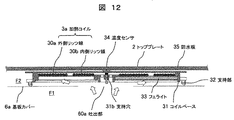
図11は実施例2に係る誘導加熱調理器の分解斜視図であり、基板カバー6a、6bと加熱コイル3a、3b、3cの部品構成を示す。また、図12は図11の加熱コイルの側面断面図である。図11に示すように、本実施例に示す基板カバー6a、6bには、開口部63および吐出部60aを設けている。基板カバー6a、6bの上方に設けた開口は、実施例1の吐出部60a(図2参照)より開口面積が大きくなっている。開口面積は大きいほど、平均風速が低下し吐出部60aを通過する際の通風抵抗が低減する。
FIG. 11 is an exploded perspective view of the induction heating cooker according to the second embodiment, showing the component configuration of the substrate covers 6a and 6b and the
つまり、図11に示す開口面積が大きい吐出部60aを設けることで、吸気開口部H1から排気開口部H2までの全体の通風抵抗が減少する。このため、小さいファン動力で効率よくファン装置9から送風が可能となる。また、図12に示すように、加熱コイル3aの下方から冷却風が供給できるため、低い圧力損失で加熱コイルを効率よく冷却できる。
That is, by providing the discharge portion 60a with a large opening area shown in FIG. 11, the overall ventilation resistance from the intake opening H1 to the exhaust opening H2 is reduced. Therefore, the fan device 9 can efficiently blow air with a small fan power. Further, as shown in FIG. 12, since the cooling air can be supplied from below the
一方、トッププレート2の亀裂などで液体が浸入した場合に、基板カバー6a、6bに設けた吐出部60aから露出している基板7a、7bの電子部品71を保護するため、本実施例の加熱コイル3aには、トッププレート2との間隙に加熱コイル3aの外形より大きい防水板35を設置している。防水板35は調理鍋の誘導加熱に影響しない材料であれば限定しないが、例えばマイカ板であれば、安価で成型も容易であるので製造が容易である。本実施例の加熱コイル3a、3b、3cの下方に設けた基板カバー6a、6bの吐出部60aは防水板35で覆うことができるため、実施例1と同様にトッププレート割れ時の液体侵入を抑制し、安全で信頼性能高い誘導加熱調理器を提供できる。
On the other hand, when the liquid enters due to cracks in the
実施例3は、実施例1と比較して基板カバー6a、6bおよび表示部P1の構成が異なるが、その他については実施例1と同様である。したがって、当該異なる部分について説明し、実施例1と重複する部分については説明を省略する。 The third embodiment is different from the first embodiment in the configuration of the substrate covers 6a and 6b and the display portion P1, but is otherwise the same as the first embodiment. Therefore, the different part will be described, and the description of the part overlapping with the first embodiment will be omitted.
図13は実施例3に係る誘導加熱調理器の基板カバーと加熱コイルの斜視図であり、基板カバー6a、6bによる他の風路構成例を示す。また、図14は図13の基板カバー6a、6bに冷却風の主要な流れを示す誘導加熱調理器の側面断面図である。図13に示すように、本実施例では本体正面側の基板カバー6a、6bを開放面としており、ファン装置9から吹出す空気が流入するヒートシンク(8a、8b、図2参照)の下流側に広い空間を構成したものである。本構成ではヒートシンクのフィン間に空気が流入し易くなり、風路の通風抵抗を低減できる。なお、本実施例では図14に示すように、基板7a(7b)を冷却する風路F1と、加熱コイル3a(3b、3c)を冷却する風路F2が、基板カバー6a(6b)と表示部P1で仕切られて分離している構成となる。基板カバー6a(6b)と表示部P1の嵌合部(図示せず)は、リブ等でラビリンスシール(非接触シール)を構成してもよいし、パッキン等(接触シール)を用いた構成であってもよい。また、この嵌合部には加熱コイル3a(3b)を冷却する開口を設け吐出部60aを構成すれば、加熱コイル3a(3b)に対し任意の位置から冷却風を供給して冷却効率を向上できる。なお、表示部P1に鍔部61を設け、冷却風の流れ方向を限定すれば加熱コイル3a(3b)をより効果的に冷却できる。
FIG. 13 is a perspective view of the substrate cover and the heating coil of the induction heating cooker according to the third embodiment, and shows another example of the air passage configuration by the substrate covers 6a and 6b. Further, FIG. 14 is a side sectional view of the induction heating cooker showing the main flow of the cooling air on the substrate covers 6a and 6b of FIG. As shown in FIG. 13, in the present embodiment, the substrate covers 6a and 6b on the front side of the main body are open surfaces, and are placed on the downstream side of the heat sinks (8a and 8b, see FIG. 2) into which the air blown from the fan device 9 flows. It constitutes a large space. With this configuration, air easily flows between the fins of the heat sink, and the ventilation resistance of the air passage can be reduced. In this embodiment, as shown in FIG. 14, the air passage F1 for cooling the substrate 7a (7b) and the air passage F2 for cooling the
Z 誘導加熱調理器、
1 本体、
2 トッププレート、
21 鍋載置部、
22 操作部、 3a、3b、3c 加熱コイル、
31 コイルベース、
32 指示部、
34 温度センサ、
5 グリル庫、
6a、6b 基板カバー、
6c 蓋部、
60a 吐出部、
65a、65b 通風ダクト、
66、66a、66b、66c リブ、
7a、7b 基板、
71 電子部品、
72(72a、72b、73b、73x) 高発熱素子、
73a、73b 基板台、
77 中継コネクタ、
8a、8b ヒートシンク、
9 ファン装置、
9a 吸気口、
90a、90b ケーシング、
91 インペラ、
92 モータ、
95 吐出口、
F0 チャンバ部、
H1 吸気開口部、
H2 排気開口部、
P1 表示部、 P2 操作パネル
Z induction cooker,
1 body,
2 top plate,
21 pot placement section,
22 operation part, 3a, 3b, 3c heating coil,
31 coil base,
32 instruction section,
34 temperature sensor,
5 grill storage,
6a, 6b substrate cover,
6c lid,
60a discharge part,
65a, 65b ventilation duct,
66, 66a, 66b, 66c ribs,
7a, 7b substrate,
71 electronic components,
72 (72a, 72b, 73b, 73x) high heat generating element,
73a, 73b substrate stand,
77 relay connector,
8a, 8b heat sink,
9 fan device,
9a intake port,
90a, 90b casing,
91 Impeller,
92 motor,
95 outlet,
F0 chamber part,
H1 intake opening,
H2 exhaust opening,
P1 display, P2 operation panel
Claims (5)
該本体の上面に設置するトッププレートと、
該トッププレートの下方に設ける加熱コイルと、
前記加熱コイルよりも下方に配置されるとともに、前記加熱コイルに高周波電流を供給するインバータ基板と、
該インバータ基板を冷却するファン装置と、
前記加熱コイルを載置するとともに、前記インバータ基板を概ね覆う基板カバーと、を備えた誘導加熱調理器であって、
前記インバータ基板は、本体上面視において、前記基板カバーが覆わない位置に中継コネクタを設けており、
該中継コネクタの上方であって前記基板カバーが覆わない領域を、着脱可能な蓋部で覆い、前記ファン装置から前記インバータ基板に向かう風路を構成したことを特徴とする誘導加熱調理器。 Body,
A top plate installed on the upper surface of the main body,
A heating coil provided below the top plate,
An inverter board arranged below the heating coil and supplying a high-frequency current to the heating coil,
A fan device for cooling the inverter board;
An induction heating cooker including the heating coil and a substrate cover that substantially covers the inverter substrate,
The inverter board is provided with a relay connector at a position not covered by the board cover in a top view of the main body,
An induction heating cooker, characterized in that a region above the relay connector and not covered by the substrate cover is covered with a detachable lid part to form an air passage from the fan device to the inverter substrate.
各々のインバータ基板は略平面状に配置され、
前記蓋部は、本体上面視において、前記複数の加熱コイルの間隙に配置されていることを特徴とする請求項1に記載の誘導加熱調理器。 The heating coil and the inverter board are respectively provided in plurality,
Each inverter board is arranged in a substantially planar shape,
The induction heating cooker according to claim 1, wherein the lid portion is arranged in a gap between the plurality of heating coils in a top view of the main body.
前記基板カバーと前記表示部により、前記複数の加熱コイルを設置した空間と前記複数のインバータ基板を設置した空間を分離したことを特徴とする請求項1乃至3の何れか一項に記載の誘導加熱調理器。 A display unit is arranged below the top plate and on the front side of the main body,
The guide according to any one of claims 1 to 3, wherein the board cover and the display section separate a space in which the plurality of heating coils are installed from a space in which the plurality of inverter boards are installed. Heating cooker.
Priority Applications (1)
| Application Number | Priority Date | Filing Date | Title |
|---|---|---|---|
| JP2017040147A JP6730209B2 (en) | 2017-03-03 | 2017-03-03 | Induction cooker |
Applications Claiming Priority (1)
| Application Number | Priority Date | Filing Date | Title |
|---|---|---|---|
| JP2017040147A JP6730209B2 (en) | 2017-03-03 | 2017-03-03 | Induction cooker |
Publications (2)
| Publication Number | Publication Date |
|---|---|
| JP2018147641A JP2018147641A (en) | 2018-09-20 |
| JP6730209B2 true JP6730209B2 (en) | 2020-07-29 |
Family
ID=63591419
Family Applications (1)
| Application Number | Title | Priority Date | Filing Date |
|---|---|---|---|
| JP2017040147A Active JP6730209B2 (en) | 2017-03-03 | 2017-03-03 | Induction cooker |
Country Status (1)
| Country | Link |
|---|---|
| JP (1) | JP6730209B2 (en) |
Cited By (2)
| Publication number | Priority date | Publication date | Assignee | Title |
|---|---|---|---|---|
| EP4007450A1 (en) * | 2020-11-25 | 2022-06-01 | LG Electronics Inc. | Electric range |
| EP4007451A1 (en) * | 2020-11-25 | 2022-06-01 | LG Electronics Inc. | Electric range |
Families Citing this family (4)
| Publication number | Priority date | Publication date | Assignee | Title |
|---|---|---|---|---|
| JP7055088B2 (en) * | 2018-11-15 | 2022-04-15 | 三菱電機株式会社 | Cookware and kitchen furniture |
| JP7325373B2 (en) * | 2020-05-07 | 2023-08-14 | 三菱電機株式会社 | induction cooker |
| JP7323565B2 (en) | 2021-03-17 | 2023-08-08 | 日立グローバルライフソリューションズ株式会社 | heating cooker |
| EP4350219A1 (en) * | 2021-05-28 | 2024-04-10 | LG Electronics Inc. | Electric range |
Family Cites Families (3)
| Publication number | Priority date | Publication date | Assignee | Title |
|---|---|---|---|---|
| JP2006031946A (en) * | 2004-07-12 | 2006-02-02 | Hitachi Home & Life Solutions Inc | Circuit substrate and induction heating cooking apparatus using the same |
| JP2011060494A (en) * | 2009-09-08 | 2011-03-24 | Toshiba Corp | Heating cooker |
| JP6670567B2 (en) * | 2015-08-19 | 2020-03-25 | 日立グローバルライフソリューションズ株式会社 | Induction heating cooker |
-
2017
- 2017-03-03 JP JP2017040147A patent/JP6730209B2/en active Active
Cited By (2)
| Publication number | Priority date | Publication date | Assignee | Title |
|---|---|---|---|---|
| EP4007450A1 (en) * | 2020-11-25 | 2022-06-01 | LG Electronics Inc. | Electric range |
| EP4007451A1 (en) * | 2020-11-25 | 2022-06-01 | LG Electronics Inc. | Electric range |
Also Published As
| Publication number | Publication date |
|---|---|
| JP2018147641A (en) | 2018-09-20 |
Similar Documents
| Publication | Publication Date | Title |
|---|---|---|
| JP6730209B2 (en) | Induction cooker | |
| JP6670567B2 (en) | Induction heating cooker | |
| JP2009283392A (en) | Heating cooker | |
| JP5604384B2 (en) | Induction heating cooker | |
| JP6858102B2 (en) | Induction heating cooker | |
| JP7039522B2 (en) | Cooker | |
| JP2006031946A (en) | Circuit substrate and induction heating cooking apparatus using the same | |
| JP6633472B2 (en) | Induction heating cooker | |
| JP2005005131A (en) | Induction heating cooking device | |
| JP6893196B2 (en) | Induction heating cooker | |
| JP5897183B2 (en) | Cooker | |
| JP2021048030A (en) | Induction cooker | |
| JP2017068940A (en) | Induction heating cooker | |
| JP7042234B2 (en) | Cooker | |
| JP6887395B2 (en) | Induction heating cooker | |
| JP5063767B2 (en) | Induction heating cooker | |
| JP7096787B2 (en) | Cooker | |
| JP7072544B2 (en) | Cooker | |
| JP5897194B2 (en) | Cooker | |
| JP2009283394A (en) | Heating cooker | |
| JP4972617B2 (en) | Induction heating cooker | |
| JP2012104246A (en) | Induction heating cooker | |
| JP7390876B2 (en) | induction heating cooker | |
| JP4366415B2 (en) | Induction heating cooker | |
| JP2016018624A (en) | Induction heating cooker |
Legal Events
| Date | Code | Title | Description |
|---|---|---|---|
| A621 | Written request for application examination |
Free format text: JAPANESE INTERMEDIATE CODE: A621 Effective date: 20190823 |
|
| TRDD | Decision of grant or rejection written | ||
| A01 | Written decision to grant a patent or to grant a registration (utility model) |
Free format text: JAPANESE INTERMEDIATE CODE: A01 Effective date: 20200630 |
|
| A977 | Report on retrieval |
Free format text: JAPANESE INTERMEDIATE CODE: A971007 Effective date: 20200626 |
|
| A61 | First payment of annual fees (during grant procedure) |
Free format text: JAPANESE INTERMEDIATE CODE: A61 Effective date: 20200702 |
|
| R150 | Certificate of patent or registration of utility model |
Ref document number: 6730209 Country of ref document: JP Free format text: JAPANESE INTERMEDIATE CODE: R150 |