JP6719084B2 - Rotary impact tool - Google Patents
Rotary impact tool Download PDFInfo
- Publication number
- JP6719084B2 JP6719084B2 JP2016188779A JP2016188779A JP6719084B2 JP 6719084 B2 JP6719084 B2 JP 6719084B2 JP 2016188779 A JP2016188779 A JP 2016188779A JP 2016188779 A JP2016188779 A JP 2016188779A JP 6719084 B2 JP6719084 B2 JP 6719084B2
- Authority
- JP
- Japan
- Prior art keywords
- hammer
- spindle
- guide groove
- rotation axis
- main
- Prior art date
- Legal status (The legal status is an assumption and is not a legal conclusion. Google has not performed a legal analysis and makes no representation as to the accuracy of the status listed.)
- Active
Links
Images

Classifications
-
- B—PERFORMING OPERATIONS; TRANSPORTING
- B25—HAND TOOLS; PORTABLE POWER-DRIVEN TOOLS; MANIPULATORS
- B25B—TOOLS OR BENCH DEVICES NOT OTHERWISE PROVIDED FOR, FOR FASTENING, CONNECTING, DISENGAGING OR HOLDING
- B25B21/00—Portable power-driven screw or nut setting or loosening tools; Attachments for drilling apparatus serving the same purpose
- B25B21/02—Portable power-driven screw or nut setting or loosening tools; Attachments for drilling apparatus serving the same purpose with means for imparting impact to screwdriver blade or nut socket
- B25B21/026—Impact clutches
-
- B—PERFORMING OPERATIONS; TRANSPORTING
- B25—HAND TOOLS; PORTABLE POWER-DRIVEN TOOLS; MANIPULATORS
- B25B—TOOLS OR BENCH DEVICES NOT OTHERWISE PROVIDED FOR, FOR FASTENING, CONNECTING, DISENGAGING OR HOLDING
- B25B21/00—Portable power-driven screw or nut setting or loosening tools; Attachments for drilling apparatus serving the same purpose
- B25B21/02—Portable power-driven screw or nut setting or loosening tools; Attachments for drilling apparatus serving the same purpose with means for imparting impact to screwdriver blade or nut socket
-
- B—PERFORMING OPERATIONS; TRANSPORTING
- B25—HAND TOOLS; PORTABLE POWER-DRIVEN TOOLS; MANIPULATORS
- B25D—PERCUSSIVE TOOLS
- B25D16/00—Portable percussive machines with superimposed rotation, the rotational movement of the output shaft of a motor being modified to generate axial impacts on the tool bit
Landscapes
- Engineering & Computer Science (AREA)
- Mechanical Engineering (AREA)
- Percussive Tools And Related Accessories (AREA)
Description
本発明は、回転打撃工具に関する。 The present invention relates to a rotary impact tool.
回転打撃工具では、ハンマがばねによりアンビル側に付勢されることでハンマ爪とアンビル爪とが周方向に係合し、ハンマの回転がアンビルに伝達される。アンビルに所定値を超える負荷トルクが加わると、ハンマはばね付勢力に抗して後退する。ハンマの後退によりハンマ爪とアンビル爪の係合が外れると、ハンマは回転しながら前進して、ハンマ爪がアンビル爪に回転方向の打撃を加える。このときの回転打撃により回転軸線方向に衝撃が発生するが、回転軸線方向に生じる衝撃はボルトやナットの締め付けに寄与せず、工具本体に振動として伝達されるため、可能な限り低減させることが好ましい。 In the rotary impact tool, the hammer is urged toward the anvil by the spring so that the hammer claw and the anvil claw engage with each other in the circumferential direction, and the rotation of the hammer is transmitted to the anvil. When a load torque exceeding a predetermined value is applied to the anvil, the hammer retracts against the spring biasing force. When the hammer claws are disengaged from the anvil claws, the hammer moves forward while rotating, and the hammer claws strike the anvil claws in the rotational direction. An impact is generated in the rotation axis direction by the rotation impact at this time, but the impact generated in the rotation axis direction does not contribute to the tightening of the bolts and nuts and is transmitted to the tool body as vibration, so it can be reduced as much as possible. preferable.
特許文献1は、駆動部によって回転されるスピンドルと、スピンドルの回転軸線方向の前方に配置されたアンビルと、スピンドルの回転を回転打撃に変換してアンビルに伝達する回転打撃機構とを備えたインパクトレンチを開示する。回転打撃機構は、スピンドルの回転軸線を中心に回転可能かつ軸線方向に移動可能な主ハンマと、主ハンマと一体となって回転する一方で軸線方向には移動しない副ハンマとを備える。特許文献1に開示されるインパクトレンチでは、スピンドル側の案内溝と主ハンマ側の係合溝との間に鋼球を配置したカム構造が設けられ、主ハンマがカム構造により後退と前進を高速で繰り返すことでアンビルに回転打撃力を付与する。
回転軸線方向の衝撃の大きさは、アンビルを打撃するハンマの質量に比例し、回転方向の衝撃の大きさは、回転するハンマの慣性モーメント(物体内の各部分の質量と、その部分から回転軸線までの距離の2乗との積の総和)に比例する。特許文献1のインパクトレンチはダブルハンマ構成を採用し、回転方向の衝撃にのみ寄与する副ハンマの質量を主ハンマの質量より大きくすることで、回転方向の衝撃の大きさを維持しつつ、主ハンマによる回転軸線方向の衝撃を小さくしている。
本発明者らは、特許文献1に開示されるダブルハンマ構成に変更を加えることで、工具本体に伝達される回転軸線方向の振動を低減させる技術を想到するに至った。
The magnitude of the impact in the direction of the rotation axis is proportional to the mass of the hammer striking the anvil, and the magnitude of the impact in the direction of rotation is the moment of inertia of the rotating hammer (the mass of each part in the body and the rotation from that part). It is proportional to the sum of the product of the distance to the axis and the square. The impact wrench of
The present inventors have come up with a technique for reducing the vibration in the rotation axis direction transmitted to the tool body by modifying the double hammer configuration disclosed in
本発明はこうした状況に鑑みなされたものであり、その目的は、主ハンマと副ハンマとを有する回転打撃工具において、工具本体に伝達される回転軸線方向の振動を低減させる技術を提供することにある。 The present invention has been made in view of these circumstances, and an object thereof is to provide a technique for reducing vibration in a rotation axis direction transmitted to a tool body in a rotary impact tool having a main hammer and a sub-hammer. is there.
上記課題を解決するために、本発明のある態様の回転打撃工具は、駆動部と、駆動部により回転されるスピンドルと、スピンドルの回転軸線を中心に回転可能且つ回転軸線方向に移動可能な主ハンマと、スピンドル側の第1案内溝と主ハンマ側の第1係合溝との間に第1鋼球を配置した第1カム構造と、主ハンマにより回転打撃力が加えられるアンビルと、主ハンマと一体に回転可能な副ハンマと、第1案内溝の後方側に設けられて第1案内溝が形成されたスピンドルの部分より大きい外径を有する大径部と、大径部側の第2案内溝と副ハンマ側の第2係合溝との間に第2鋼球を配置した第2カム構造とを備える。この態様の回転打撃工具は、主ハンマが回転軸線方向に移動すると、副ハンマが主ハンマの移動方向とは逆方向に移動するように構成される。 In order to solve the above-described problems, a rotary impact tool according to an aspect of the present invention is a main drive unit, a spindle rotated by the drive unit, a main shaft that is rotatable about a rotation axis of the spindle and movable in a rotation axis direction. A hammer, a first cam structure in which a first steel ball is arranged between a first guide groove on the spindle side and a first engaging groove on the main hammer side, an anvil to which a rotational impact force is applied by the main hammer, A sub-hammer that is rotatable integrally with the hammer, a large-diameter portion that has a larger outer diameter than the portion of the spindle that is provided on the rear side of the first guide groove and in which the first guide groove is formed, and a large-diameter portion And a second cam structure in which a second steel ball is arranged between the second guide groove and the second engagement groove on the auxiliary hammer side. In the rotary impact tool of this aspect, when the main hammer moves in the rotation axis direction, the sub hammer moves in the direction opposite to the moving direction of the main hammer.
本発明によれば、主ハンマと副ハンマとを有する回転打撃工具において、工具本体に伝達される回転軸線方向の振動を低減させる技術を提供できる。 According to the present invention, in a rotary impact tool having a main hammer and a sub-hammer, it is possible to provide a technique for reducing vibration in the rotational axis direction transmitted to the tool body.
実施形態の回転打撃工具は、駆動部により回転されるスピンドルと、スピンドルの回転軸線方向の前方に配置されたアンビルと、スピンドルの回転を回転打撃に変換してアンビルに伝達する回転打撃機構とを備える。回転打撃機構はダブルハンマ構成を採用し、スピンドルの回転軸線を中心に回転可能かつ軸線方向に移動可能な主ハンマと、主ハンマと一体に回転可能な副ハンマを備える。回転打撃機構は、主ハンマをアンビルに衝撃的に係合させて、アンビルを軸線回りに回転させる機能をもつ。 The rotary impact tool of the embodiment includes a spindle rotated by a drive unit, an anvil arranged in front of the spindle in the direction of the rotation axis, and a rotary impact mechanism that converts the rotation of the spindle into rotary impact to transmit to the anvil. Prepare The rotary striking mechanism adopts a double hammer structure, and is provided with a main hammer that is rotatable about the rotation axis of the spindle and movable in the axial direction, and an auxiliary hammer that is rotatable integrally with the main hammer. The rotary striking mechanism has a function of shock-engaging the main hammer with the anvil to rotate the anvil around its axis.
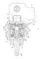
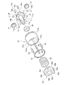
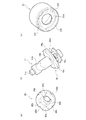
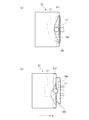
図1は、実施形態に係る回転打撃工具の主要部の断面概略図を示す。図1において一点鎖線は、回転打撃工具1における回転軸線を示している。図2は、実施形態に係る回転打撃機構の構成部品の分解斜視図を示し、図3は、実施形態に係る回転打撃機構の組立斜視図を示す。なお図3では見やすさのために、後述する止め部材27の図示を省略している。図4(a)は主ハンマの前面側斜視図を示し、図4(b)はスピンドルおよびキャリアの斜視図を示し、図4(c)は副ハンマの後面側斜視図を示す。以下、図1〜図4を用いて、回転打撃工具1の構造について説明する。
FIG. 1 shows a schematic cross-sectional view of a main part of a rotary impact tool according to an embodiment. In FIG. 1, the alternate long and short dash line indicates the axis of rotation of the
回転打撃工具1は、工具本体を構成するハウジング2を備える。ハウジング2の上部は、各種構成部品を収容するための収容空間を形成し、ハウジング2の下部は、ユーザにより把持される把持部3を構成する。把持部3の前側には、ユーザの手指により操作される操作スイッチ4が設けられ、把持部3の下端部には、駆動部10に電力を供給するバッテリ(図示せず)が設けられる。
The
駆動部10は電動モータであって、駆動部10の駆動軸10aは、動力伝達機構12を介してキャリア16およびスピンドル11に連結される。キャリア16はスピンドル11の後端側に位置して、動力伝達用の歯車を収容する。図4(b)を参照してキャリア16は、スピンドル11より大きい外径を有する大径部として構成される。キャリア16は、スピンドル11より大径の前側部材16bと、前側部材16bよりも後方に位置する後側部材16cとを有し、前側部材16bと後側部材16cとの間に歯車を収容するための空間16dを形成する。
The
動力伝達機構12は、駆動軸10aの先端に圧入固定される太陽歯車13と、太陽歯車13に噛合する2個の遊星歯車14と、遊星歯車14に噛合する内歯車15とを有する。遊星歯車14はキャリア16の空間16dにおいて、前側部材16bおよび後側部材16cに固定される支軸14aにより回転可能に支持される。内歯車15は、ハウジング2の内周面に固定されている。
The
以上のように構成した動力伝達機構12により、駆動軸10aの回転が、太陽歯車13の歯数と内歯車15の歯数との比に基づいて減速されるとともに、その回転トルクが増大される。これによりキャリア16およびスピンドル11を低速高トルクで駆動できるようになる。
With the
回転打撃工具1の回転打撃機構は、スピンドル11、キャリア16、主ハンマ20、副ハンマ21およびばね部材23によって構成される。スピンドル11は円柱状に形成され、その先端には、小径の突起部11aがスピンドル11の軸線と同軸に形成される。突起部11aは、アンビル22の後部に形成した円柱状の内部空間を有する孔に回転可能な状態で挿入される。
The rotary impact mechanism of the
スピンドル11の外周には、略円盤状であって中心部に貫通孔を形成した鋼製の主ハンマ20が装着される。主ハンマ20の前面には、アンビル22に向けて突出する一対のハンマ爪20aが形成される。主ハンマ20は、スピンドル11の回転軸線を中心に回転可能であり、且つスピンドル11の回転軸線方向すなわち前後方向に移動可能となるように、スピンドル11に取り付けられる。これにより主ハンマ20は、アンビル22に対して回転打撃力を加えられるようになる。副ハンマ21は鋼製の円筒部材として形成され、環状仕切部21eにより前部21aと後部21bに仕切られる。副ハンマ21は、前部21aの内部空間に主ハンマ20を収容する。
On the outer circumference of the
副ハンマ21と主ハンマ20は、一体となって回転する一体回転機構を備える。図2を参照して、主ハンマ20は、その外周面に、断面が半円形でスピンドル11の回転軸線と平行な4つの第1ピン溝20dを備える。また副ハンマ21は、前部21aの内周面に、断面が半円形でスピンドル11の回転軸線と平行な4つの第2ピン溝21cを備える。ここで副ハンマ21の4つの第2ピン溝21cは、主ハンマ20の4つの第1ピン溝20dに対応する位置に形成される。第1ピン溝20dは、主ハンマ20の外周面において90度の間隔で形成されてよく、このとき第2ピン溝21cは、副ハンマ21の内周面において90度の間隔で形成される。
The sub-hammer 21 and the
第2ピン溝21cには、円柱部材である係合ピン26が配設される。係合ピン26は、針状コロであってよい。係合ピン26は、副ハンマ21の前端側から第2ピン溝21cに挿入され、溝底部まで差し込まれる。係合ピン26を溝底部まで差し込んだ状態で、副ハンマ21の内周面に形成された環状溝21dに、係合ピン26の抜け止め機能をもつ止め部材27が嵌め込まれる。止め部材27が環状溝21dに配設されることで、第2ピン溝21cにおける係合ピン26の移動が制限される。
An
組付時、副ハンマ21の4つの第2ピン溝21cに4つの係合ピン26を取り付けた状態で、主ハンマ20の4つの第1ピン溝20dと4つの係合ピン26の位置を合わせて、主ハンマ20を副ハンマ21に挿入する。これにより主ハンマ20と副ハンマ21とは、スピンドル11の回転軸線を中心として一体となって回転可能となる。
At the time of assembling, with the four
主ハンマ20は後部側に、環状の凹部20cを有する。ばね部材23は、主ハンマ20の凹部20cと、副ハンマ21の環状仕切部21eとの間に介装される。主ハンマ20は係合ピン26をガイドとして前後方向に移動可能であり、ばね部材23の付勢力によりアンビル22に回転打撃力を加えることができる。
The
スピンドル11は、その外周面に2つの第1案内溝11bを備え、主ハンマ20は、貫通孔の内周面に2つの第1係合溝20bを備える。2つの第1案内溝11bは同一形状を有して周方向に並べて設けられ、また2つの第1係合溝20bは同一形状を有して周方向に並べて設けられる。スピンドル11の外周に主ハンマ20を装着した状態で、第1案内溝11bおよび第1係合溝20bの間には鋼球19が配置される。スピンドル11側の第1案内溝11bと、主ハンマ20側の第1係合溝20bと、両者の間に配置された鋼球19は「第1カム構造」を構成する。2つの鋼球19は、主ハンマ20がスピンドル11の回転軸線を中心に回転可能且つ回転軸線方向に移動可能となるように主ハンマ20を径方向に支持する。
The
スピンドル11よりも大径のキャリア16は、前側部材16bの前面外周に3つの第2案内溝16aを備え、副ハンマ21は、環状仕切部21eの後面に3つの第2係合溝21fを備える。3つの第2案内溝16aは同一形状を有して周方向に並べて設けられ、また3つの第2係合溝21fは同一形状を有して周方向に並べて設けられる。副ハンマ21にスピンドル11を挿入した状態で、第2案内溝16aおよび第2係合溝21fの間には鋼球17が配置される。鋼球17は製造コストの観点から、鋼球19と同一の鋼球であることが好ましい。つまり鋼球17は鋼球19と同じ材料で形成されて、同じ大きさを有すること好ましい。キャリア16側の第2案内溝16aと、副ハンマ21側の第2係合溝21fと、両者の間に配置された鋼球17は「第2カム構造」を構成する。3つの鋼球17は、副ハンマ21がスピンドル11の回転軸線を中心に回転可能且つ回転軸線方向に移動可能となるように副ハンマ21を回転軸線方向に支持する。
The
第1カム構造において、第1案内溝11bは、工具先端側からみてV字ないしはU字形状に形成されている。つまり第1案内溝11bは、最前部から対称に後斜め方向に傾斜する2つの傾斜溝をもつ。第1係合溝20bは、工具先端側からみて逆向きのV字ないしはU字形状に形成されている。鋼球19が第1案内溝11bの最前部から傾斜溝に沿って移動すると、主ハンマ20はスピンドル11に対して相対的に後退することになる。
In the first cam structure, the
第2カム構造において、第2案内溝16aは、工具後端側からみてV字ないしはU字形状に形成されている。つまり第2案内溝16aは、最後部から対称に前斜め方向に傾斜する2つの傾斜溝をもつ。第2係合溝21fは、工具後端側からみて逆向きのV字ないしはU字形状に形成されている。鋼球17が第2案内溝16aの最後部から傾斜溝に沿って移動すると、副ハンマ21はキャリア16に対して相対的に前進することになる。
In the second cam structure, the
このように第1案内溝11bと第2案内溝16aは、回転軸線方向において互いに異なる向きに延びる傾斜溝を備えて形成される。第1カム構造および第2カム構造により、主ハンマ20が回転軸線方向に移動すると、主ハンマ20と一体回転する副ハンマ21が主ハンマ20の移動方向とは逆方向に移動する構成が実現される。つまり回転軸線方向において主ハンマ20が後退するときには副ハンマ21が前進し、主ハンマ20が前進するときには副ハンマ21が後退する。
As described above, the
ストッパ部材30は主ハンマ20とキャリア16の間に設けられて、第1カム構造における鋼球19および第2カム構造における鋼球17がそれぞれの傾斜溝の端部に衝突しないように、主ハンマ20の回転軸線方向の移動範囲を規制する。ストッパ部材30は、たとえば樹脂材料で形成されてよい。
The
主ハンマ20に係合するアンビル22は鋼製であり、鋼製もしくは黄銅製の滑り軸受を介してハウジング2に回転自在に支持されている。アンビル22の先端には、6角ボルトの頭部や6角ナットに装着するソケット体を取り付けるための、断面が四角形状の工具装着部22aが設けられる。
The
アンビル22の後部には、主ハンマ20の一対のハンマ爪20aに係合する一対のアンビル爪が設けられる。一対のアンビル爪は、それぞれ断面扇形の柱状部材として形成される。なおアンビル22のアンビル爪および主ハンマ20のハンマ爪20aは、必ずしも2個である必要はなく、それぞれの爪の数が等しければ、アンビル22および主ハンマ20の周方向に等間隔に3個以上設けてもよい。
A pair of anvil claws that engage with the pair of
次に、実施形態の回転打撃工具1における第1カム構造の動作を説明する。
ユーザによる操作スイッチ4の引き操作により駆動部10が回転駆動すると、動力伝達機構12を介してキャリア16およびスピンドル11が回転する。スピンドル11の回転力は、スピンドル11の第1案内溝11bと主ハンマ20の第1係合溝20bの間に嵌め込まれた鋼球19を介して主ハンマ20に伝達され、主ハンマ20および副ハンマ21が一体となって回転する。
Next, the operation of the first cam structure in the
When the
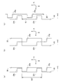
図5(a)は、ボルトやナットの締め付け開始直後の第1カム構造の状態を示し、図5(b)は、締め付け開始から時間経過後の第1カム構造の状態を示す。なお図5(b)は、図5(a)に示す第1カム構造の初期状態と比較するための比較図であり、鋼球19が第1案内溝11bの最前部から溝端部に向かって移動する様子を示している。この比較図では、鋼球19が溝端部近傍まで移動している様子が示されているが、実施形態では後述するように、第1カム構造よりも第2カム構造の周方向可動域が狭いために、鋼球19は溝端部手前を可動限界として移動する。
5A shows the state of the first cam structure immediately after the start of tightening the bolts and nuts, and FIG. 5B shows the state of the first cam structure after a lapse of time from the start of tightening. Note that FIG. 5B is a comparison diagram for comparison with the initial state of the first cam structure shown in FIG. 5A, in which the
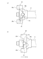
図6(a)〜図6(c)は、主ハンマ20とアンビル22の係合面を周方向に模式的に展開した位置関係を示す。ここで図6(a)は、ボルトやナットの締め付け開始直後の主ハンマ20のハンマ爪20aとアンビル22のアンビル爪22bとの係合状態を示している。
6A to 6C show a positional relationship in which the engagement surfaces of the
図6(a)〜図6(c)に示すように、主ハンマ20には、駆動部10の回転による回転力Aが矢印で示す方向に加わる。また主ハンマ20には、ばね部材23による前進方向の付勢力Bが矢印で示す方向に加わる。
As shown in FIGS. 6A to 6C, a rotational force A due to the rotation of the
主ハンマ20が回転すると、ハンマ爪20aとアンビル爪22bとの周方向の係合により、主ハンマ20の回転力がアンビル22に伝達される。そしてアンビル22の回転によって、工具装着部22aに取付けられたソケット体(図示せず)が回転し、ボルトやナットに回転力を与えて初期の締め付けが行われる。ばね部材23が主ハンマ20に対して付勢力Bを加えているため、鋼球19は、図5(a)に示すように、第1案内溝11bにおける最前部に位置する。このときハンマ爪20aとアンビル爪22bとは、最大係合長で係合した状態にある。
When the
ボルトやナットの締め付けが進むに伴ってアンビル22に加わる負荷トルクが大きくなると、主ハンマ20にY方向の回転力が生じる。そして負荷トルクが所定値を超えると、ばね部材23の付勢力Bに抗して、鋼球19が第1案内溝11bおよび第1係合溝20bの斜面に沿って矢印Fで示す方向に移動し、主ハンマ20が後退する方向(X方向)に移動する。
When the load torque applied to the
そして鋼球19が傾斜溝内を移動して、主ハンマ20がX方向に、ハンマ爪20aとアンビル爪22bとの最大係合長分の距離を移動すると、図6(b)に示すように、ハンマ爪20aとアンビル爪22bとの係合が解除される。
Then, when the
ハンマ爪20aがアンビル爪22bから外れると、押し縮められたばね部材23の付勢力Bが開放されることによって、主ハンマ20は高速で、回転力Aが加えられている方向に回転しながら、付勢力Bにより前進する。
When the
そして図6(c)に示すように、ハンマ爪20aが、矢印Gで示す軌跡で移動してアンビル爪22bに衝突し、アンビル22に回転方向の打撃力を付与する。その後、反動によりハンマ爪20aは、軌跡Gとは逆方向に移動するが、最終的には、回転力Aおよび付勢力Bにより図6(a)に示す状態に戻る。以上の動作が高速で繰り返され、主ハンマ20による回転打撃力がアンビル22に対して繰り返し付与される。
Then, as shown in FIG. 6C, the
以上はボルトやナットを締め付ける際の動作についての説明であるが、締め付けられたボルトやナットを緩める際にも、回転打撃機構により締め付け時と同様の動作が行われる。この場合、駆動部10を締め付け時とは逆方向に回転させることにより、鋼球19が図5(a)に示す第1案内溝11bに沿って右上方に移動し、ハンマ爪20aがアンビル爪22bを、締め付け時とは逆方向に打撃する。
The above is the description of the operation when tightening the bolts and nuts, but also when loosening the tightened bolts and nuts, the same operation as when tightening is performed by the rotary striking mechanism. In this case, by rotating the
実施形態の回転打撃工具1はダブルハンマ構成を採用するため、回転方向の衝撃の大きさは、主ハンマ20および副ハンマ21の合計の慣性モーメントに比例する一方で、回転軸線方向の衝撃の大きさは、主ハンマ20の質量に比例する。回転打撃工具1によれば、副ハンマ21の質量を主ハンマ20の質量よりも大きくすることで、主ハンマ20がアンビル22に回転打撃力を付与した際に回転軸線方向に生じる衝撃力を低減できる。
Since the
主ハンマ20および副ハンマ21の合計の質量をもつ1つのハンマを用いた回転打撃工具と比較すると、実施形態の回転打撃工具1は、回転方向の衝撃の大きさをそのままに、回転軸線方向の衝撃の大きさを低減する。主ハンマ20の質量を副ハンマ21の質量と比較してできるだけ小さくすることで、回転軸線方向に生じる衝撃力をより小さくすることが可能となる。
Compared with the rotary impact tool using one hammer having the total mass of the
さらに実施形態では、慣性モーメントの大きさが回転半径の2乗に比例することを利用して、慣性モーメントの増大を図っている。すなわち質量の大きい副ハンマ21を主ハンマ20の外周側に設けることで、副ハンマ21の慣性モーメントを大きくし、ダブルハンマによる回転方向の衝撃力を増大させている。
Further, in the embodiment, the fact that the magnitude of the moment of inertia is proportional to the square of the radius of gyration is used to increase the moment of inertia. That is, by providing the
次に、第2カム構造の動作について説明する。第2カム構造は、主ハンマ20の回転軸線方向の動きとは逆向きに副ハンマ21を動かすことで、主ハンマ20により回転軸線方向に生じる衝撃を相殺して、ハウジング2に伝達される振動をさらに低減する役割をもつ。
Next, the operation of the second cam structure will be described. The second cam structure moves the sub-hammer 21 in the opposite direction to the movement of the
副ハンマ21は主ハンマ20と一体となって回転するため、副ハンマ21と主ハンマ20の周方向における相対位置は変化しない。そのため第1カム構造において鋼球19が第1案内溝11bの溝端部に向けて移動すると、第2カム構造においても鋼球17が第2案内溝16aの溝端部に向けて移動する。
Since the sub-hammer 21 rotates integrally with the
図7(a)は、ボルトやナットの締め付け開始直後の第2カム構造の状態を示し、図7(b)は、締め付け開始から時間経過後の第2カム構造の状態を示す。第1カム構造において鋼球19が第1案内溝11bの最前部に位置するとき(図5(a)参照)、第2カム構造において鋼球17は、第2案内溝16aの最後部に位置する(図7(a)参照)。
FIG. 7A shows the state of the second cam structure immediately after the start of tightening the bolts and nuts, and FIG. 7B shows the state of the second cam structure after a lapse of time from the start of tightening. When the
それから第1カム構造において鋼球19が第1案内溝11bの最前部から傾斜面に沿って移動すると、第2カム構造においても、鋼球17が第2案内溝16aの最後部から傾斜面に沿って移動する。図7(b)は、鋼球17が第2案内溝16aを移動している様子を示す。このとき副ハンマ21は、主ハンマ20の移動方向(X方向)とは逆方向に移動する。つまり主ハンマ20が後退すると、副ハンマ21は前進する。
Then, in the first cam structure, when the
このように回転打撃工具1は、第1カム構造および第2カム構造により、主ハンマ20が回転軸線方向に移動すると、副ハンマ21が主ハンマ20の移動方向とは逆方向に移動するように構成されている。副ハンマ21が主ハンマ20の移動に同期して、主ハンマ20の移動方向とは逆方向に動くことで、主ハンマ20の軸線方向の動きにより生じる振動を吸収でき、ユーザの手に伝わる振動を低減できる。
As described above, the
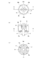
図8(a)は回転打撃機構の前面図を示す。図8(a)には、2つの鋼球19がそれぞれ第1案内溝11bの最前部に位置している様子が示される。第1案内溝11bと逆向きの形状をもつ第1係合溝20bは、鋼球19が配置されている最後部から、前方に傾斜する2つの傾斜溝を有している。
図8(b)は、回転打撃機構のC−C断面図を示す。図8(b)では、ばね部材23や遊星歯車14などの図示を省略している。この状態で3つの鋼球17がそれぞれ第2案内溝16aの最後部に位置している。
図8(c)は、回転打撃機構のD−D断面図を示す。第2案内溝16aは、鋼球17が配置されている最後部から、前方に傾斜する2つの傾斜溝を有している。
FIG. 8A shows a front view of the rotary striking mechanism. FIG. 8A shows a state in which the two
FIG.8(b) shows CC sectional drawing of a rotary impact mechanism. In FIG. 8B, the
FIG.8(c) shows DD sectional drawing of a rotary impact mechanism. The
上記したように副ハンマ21と主ハンマ20は、係合ピン26により軸線方向の相対移動を可能としつつ、軸線回りの相対回転を規制されている。副ハンマ21はばね部材23によってキャリア16側に押し付けられ、環状仕切部21eの後面が、キャリア16の前側部材16bの外周に配置された3つの鋼球17によって支持されている。
As described above, the sub-hammer 21 and the
副ハンマ21と主ハンマ20とは高速で一体回転するため、副ハンマ21と主ハンマ20の回転軸線は、スピンドル11の回転軸線に一致、つまり同軸となる必要がある。そのため副ハンマ21に関して言えば、鋼球17が、副ハンマ21とスピンドル11との同軸を維持するように、環状仕切部21eの後面を回転軸線方向に安定して支持しなければならない。
Since the sub-hammer 21 and the
そこで実施形態の回転打撃工具1は、第2案内溝16aと第2係合溝21fとの間に鋼球17を配置した第2カム構造を3つ備え、3つの鋼球17が、副ハンマ21の環状仕切部21eの後面を回転軸線方向に3点支持している。1つ又は2つの鋼球17で副ハンマ21を支持する場合と比べると、3つの鋼球17で副ハンマ21を支持することで、副ハンマ21の回転軸線方向に対する傾きを効果的に抑制し、副ハンマ21とスピンドル11との同軸を維持することが可能となる。
Therefore, the
なお鋼球17は、スピンドル11よりも大径の前側部材16bの前面外周に配置されている。スピンドル11の外周よりも前側部材16bの外周の周速度の方が大きいため、仮に第1カム構造における鋼球19と同じ数(2つ)の鋼球17で副ハンマ21を支持すると、鋼球19よりも鋼球17の摩耗が進むことが考えられる。そこで第1カム構造における鋼球19の数よりも第2カム構造における鋼球17の数を多くすることで、工具信頼性を高めることができる。
The
3つの第2カム構造は、周方向に並べて等間隔に設けられることが好ましい。これにより3つの鋼球17は、互いに120度の間隔をあけて位置することになり、副ハンマ21を安定して支持できる。
It is preferable that the three second cam structures are arranged in the circumferential direction at equal intervals. As a result, the three
なお回転打撃工具1において、鋼球17の数は3つ以上であればよい。回転打撃工具1は、第2カム構造を3つ以上備えることで、副ハンマ21とスピンドル11との同軸を確保しつつ、鋼球17の摩耗を抑制することが可能となる。4つ以上の第2カム構造が設けられる場合においても、複数の鋼球17が周方向に等間隔に位置することで、副ハンマ21を安定して支持することが好ましい。
In the
実施形態の第1カム構造と第2カム構造の周方向の可動域を比較する。実施形態では、第1カム構造が、キャリア16よりも小径のスピンドル11の外周面に、周方向に2つ並べて設けられている。そのため2つの第1案内溝11bを、スピンドル11の外周面のほぼ全周にわたって形成すると、第1案内溝11bの1つの傾斜溝の周方向可動域は略90度となる。一方、第2カム構造は、スピンドル11よりも大径のキャリア16の前面外周に周方向に3つ並べて設けられている。そのため3つの第2案内溝16aを、キャリア16の前面外周のほぼ全周にわたって形成すると、第2案内溝16aの1つの傾斜溝の周方向可動域は略60度となる。
The movable range in the circumferential direction of the first cam structure and the second cam structure of the embodiment will be compared. In the embodiment, two first cam structures are provided side by side in the circumferential direction on the outer peripheral surface of the
以上のように周方向可動域は、第2カム構造の方が狭い。このことは、第2カム構造の方が第1カム構造よりも先に可動限界に達することを意味する。そのため回転打撃工具1では、第2案内溝16aにおいて鋼球17が可動限界まで移動する前にハンマ爪20aとアンビル爪22bとの係合が解除されるように、第1カム構造および第2カム構造が形成されている。
As described above, the movable range in the circumferential direction is narrower in the second cam structure. This means that the second cam structure reaches the movable limit earlier than the first cam structure. Therefore, in the
以下、第2カム構造の第2案内溝16aを、第1カム構造の第1案内溝11bが形成されたスピンドル11よりも大径のキャリア16に形成した理由について説明する。回転打撃工具1は、ユーザが手で持って使用する電動工具であるため、小型化および軽量化に対する要請は大きい。仮に3つの第2案内溝16aをスピンドル11の外周面に形成して3つの鋼球17が副ハンマ21を径方向に支持する構造を採用した場合、スピンドル11の強度が不足することから、スピンドル自体を太くする必要がある。しかしながらスピンドル11の太径化は、小型化および軽量化の要請に沿わず好ましくない。また、この構造において、鋼球17を鋼球19よりも小さくして、3つの第2案内溝16aを形成することによる肉抜き量を減らし、スピンドル11の強度不足を防ぐことも考えられる。しかしながら鋼球17を小さくすることで今度は鋼球17の強度が問題になり、また2種類の鋼球が必要となるために製造コストが上がるという問題がある。
Hereinafter, the reason why the
そこで回転打撃工具1では、スピンドル11よりも大径のキャリア16に第2案内溝16aを形成して、上記の問題を解決している。なおスピンドル11の第1案内溝11bが形成された部分の後方側に、当該部分より大きい外径を有する大径部を設けて、大径部に第2案内溝16aを形成してもよい。この場合、スピンドル11は、第1案内溝11bが形成された小径部と、第2案内溝16aが形成された大径部とを有することになる。このときスピンドル11が大径部を有することで、スピンドル11の重量は若干増えるが、同時にキャリア16の強度は上がるため、十分な耐久力が見込める場合にはキャリア16を薄肉化(軽量化)して、工具重量が大きくならないようにしてもよい。
Therefore, in the
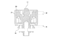
図9は、第1カム構造および第2カム構造において鋼球が移動したときの回転打撃機構の概略断面図を示す。この例では、主ハンマ20がスピンドル11に対して移動量Mだけ後退し、副ハンマ21がキャリア16に対して移動量Nだけ前進している。図6(b)に関して説明したように、主ハンマ20の移動量Mが、ハンマ爪20aとアンビル爪22bとの最大係合長分の距離に達すると、ハンマ爪20aとアンビル爪22bとの係合が解除される。上記したように、副ハンマ21の移動量Nが可動限界に達する前に、主ハンマ20の移動量Mが、ハンマ爪20aとアンビル爪22bとの最大係合長分の距離に達するように、第1カム構造および第2カム構造は形成されている。
FIG. 9 is a schematic cross-sectional view of the rotary striking mechanism when the steel ball moves in the first cam structure and the second cam structure. In this example, the
主ハンマ20の回転軸線方向の移動量Mと副ハンマ21の回転軸線方向の移動量Nは、それぞれ第1カム構造および第2カム構造の形状によって規定される。軸線方向の振動を好適に打ち消し合うための両者の移動量の比は、主ハンマ20と副ハンマ21との質量比に依存するため、第1カム構造および第2カム構造の形状は、主ハンマ20と副ハンマ21との質量比に応じて設計される。以下、主ハンマ20の質量をP、副ハンマ21の質量をQとする。質量Pは質量Qより小さい。
The movement amount M of the
実施形態では、第2案内溝16aにおける鋼球17の回転軸線方向の可動域が、第1案内溝11bにおける鋼球19の回転軸線方向の可動域よりも小さくなるように、第1カム構造および第2カム構造が形成されている。これは副ハンマ21の質量Qが主ハンマ20の質量Pよりも大きいためであり、主ハンマ20の回転軸線方向の動きにより生じる振動を、質量の大きい副ハンマ21の逆向きで且つ小さいストロークの動きにより生じる振動で相殺することを目的とする。具体的に鋼球17の回転軸線方向の可動域と鋼球19の回転軸線方向の可動域との比は、主ハンマ20の質量Pと副ハンマ21の質量Qとの比に実質的に等しく設定されてよい。
In the embodiment, the first cam structure and the first cam structure are configured so that the movable range of the
このように第1カム構造および第2カム構造を形成することで、第2案内溝16aの傾斜溝の回転軸線方向の長さを、第1案内溝11bの傾斜溝の回転軸線方向の長さよりも短くできる。このことは工具本体の短軸化を実現し、回転打撃工具1の小型化および軽量化に寄与する。
By forming the first cam structure and the second cam structure in this way, the length of the inclined groove of the
なお上記は回転軸線方向の可動域についての説明であるが、第1カム構造および第2カム構造における可動域内での傾斜溝の形状は上記設計思想により定められる。つまり副ハンマ21のキャリア16に対する移動量Nと主ハンマ20のスピンドル11に対する移動量Mとの比が、主ハンマ20の質量Pと副ハンマ21の質量Qとの比に実質的に等しくなるように、第1カム構造および第2カム構造が形成される。これにより主ハンマ20および副ハンマ21による回転軸線方向の振動が互いに打ち消し合うように作用し、ユーザの作業性を高めることが可能となる。
It should be noted that the above is a description of the movable range in the rotation axis direction, but the shape of the inclined groove in the movable range in the first cam structure and the second cam structure is determined by the above design concept. That is, the ratio of the movement amount N of the sub-hammer 21 to the
本発明の一態様の概要は、次の通りである。
本発明のある態様の回転打撃工具(1)は、駆動部(10)と、駆動部により回転されるスピンドル(11)と、スピンドルの回転軸線を中心に回転可能且つ回転軸線方向に移動可能な主ハンマ(20)と、スピンドル側の第1案内溝(11b)と主ハンマ側の第1係合溝(20b)との間に第1鋼球(19)を配置した第1カム構造と、主ハンマにより回転打撃力が加えられるアンビル(22)と、主ハンマと一体に回転可能な副ハンマ(21)と、第1案内溝の後方側に設けられて第1案内溝が形成されたスピンドルの部分より大きい外径を有する大径部(16)と、大径部側の第2案内溝(16a)と副ハンマ側の第2係合溝(21f)との間に第2鋼球(17)を配置した第2カム構造とを備える。この態様の回転打撃工具は、主ハンマが回転軸線方向に移動すると、副ハンマが主ハンマの移動方向とは逆方向に移動するように構成される。
The outline of one aspect of the present invention is as follows.
A rotary impact tool (1) according to an aspect of the present invention includes a drive unit (10), a spindle (11) rotated by the drive unit, and a rotary shaft which is rotatable about a rotation axis of the spindle and movable in the rotation axis direction. A main hammer (20), a first cam structure in which a first steel ball (19) is arranged between the first guide groove (11b) on the spindle side and the first engaging groove (20b) on the main hammer side, An anvil (22) to which a rotary hammering force is applied by the main hammer, a sub-hammer (21) rotatable integrally with the main hammer, and a spindle provided on the rear side of the first guide groove and having a first guide groove formed therein. The second steel ball (16) having an outer diameter larger than that of the second steel ball (16) between the second guide groove (16a) on the large diameter portion side and the second engagement groove (21f) on the sub-hammer side ( 17) and the second cam structure. In the rotary impact tool of this aspect, when the main hammer moves in the rotation axis direction, the sub hammer moves in the direction opposite to the moving direction of the main hammer.
大径部は、スピンドルの後端側に位置して動力伝達用の歯車を収容するキャリア(16)であってよい。スピンドル(11)は、第1案内溝が形成された小径部と、第2案内溝が形成された大径部とを有してもよい。回転打撃工具(1)において、主ハンマ(20)の質量よりも副ハンマ(21)の質量が大きいことが好ましい。 The large-diameter portion may be a carrier (16) located on the rear end side of the spindle and accommodating a gear for power transmission. The spindle (11) may have a small diameter part in which the first guide groove is formed and a large diameter part in which the second guide groove is formed. In the rotary impact tool (1), the mass of the auxiliary hammer (21) is preferably larger than the mass of the main hammer (20).
回転打撃工具(1)では、第2案内溝(16a)における第2鋼球(17)の回転軸線方向の可動域が、第1案内溝(11b)における第1鋼球(19)の回転軸線方向の可動域よりも小さくなるように、第1カム構造および第2カム構造が形成されてよい。第2鋼球の回転軸線方向の可動域と第1鋼球の回転軸線方向の可動域との比は、主ハンマの質量と副ハンマの質量との比に実質的に等しく設定されてよい。副ハンマは、主ハンマを収容してよい。主ハンマに副ハンマが外接することで、副ハンマが回転軸線を中心に回転可能に支持されてよい。第1鋼球および第2鋼球は、同じ大きさを有して構成されてよい。 In the rotary impact tool (1), the movable range in the direction of the rotation axis of the second steel ball (17) in the second guide groove (16a) is the rotation axis of the first steel ball (19) in the first guide groove (11b). The first cam structure and the second cam structure may be formed so as to be smaller than the movable range in the direction. The ratio of the movable range of the second steel ball in the rotation axis direction to the movable range of the first steel ball in the rotation axis direction may be set to be substantially equal to the ratio of the mass of the main hammer and the mass of the sub-hammer. The secondary hammer may house the primary hammer. The sub-hammer may be rotatably supported around the rotation axis by the sub-hammer being circumscribed on the main hammer. The first steel ball and the second steel ball may be configured to have the same size.
以上、本発明を実施形態をもとに説明した。この実施形態は例示であり、それらの各構成要素あるいは各処理プロセスの組合せにいろいろな変形例が可能なこと、またそうした変形例も本発明の範囲にあることは当業者に理解されるところである。 The present invention has been described above based on the embodiment. It should be understood by those skilled in the art that this embodiment is an exemplification, and various modifications can be made to the combinations of the respective constituent elements or the respective processing processes, and such modifications are also within the scope of the present invention. ..
1・・・回転打撃工具、2・・・ハウジング、11・・・スピンドル、11b・・・第1案内溝、12・・・動力伝達機構、16・・・キャリア、16a・・・第2案内溝、16b・・・前側部材、17,19・・・鋼球、20・・・主ハンマ、20a・・・ハンマ爪、20b・・・第1係合溝、21・・・副ハンマ、21e・・・環状仕切部、21f・・・第2係合溝、22・・・アンビル、22b・・・アンビル爪、23・・・ばね部材。
DESCRIPTION OF
Claims (8)
前記主ハンマが回転軸線方向に移動すると、前記副ハンマが前記主ハンマの移動方向とは逆方向に移動するように構成されたことを特徴とする回転打撃工具。 A drive unit, a spindle rotated by the drive unit, a main hammer rotatable about the rotation axis of the spindle and movable in the rotation axis direction, a first guide groove on the spindle side, and a main hammer side on the main hammer side. A first cam structure in which a first steel ball is arranged between the first engagement groove, an anvil to which a rotational impact force is applied by the main hammer, an auxiliary hammer rotatable integrally with the main hammer, the first hammer structure, A large diameter portion provided on the rear side of the first guide groove and having a larger outer diameter than the portion of the spindle in which the first guide groove is formed, a second guide groove on the large diameter portion side, and a sub-hammer side A second cam structure in which a second steel ball is arranged between the second engagement groove and the second engagement groove,
A rotary impact tool, wherein the sub-hammer is configured to move in a direction opposite to a moving direction of the main hammer when the main hammer moves in a rotation axis direction.
ことを特徴とする請求項1に記載の回転打撃工具。 The large-diameter portion is a carrier that is located on the rear end side of the spindle and accommodates a gear for power transmission.
The rotary impact tool according to claim 1, wherein:
ことを特徴とする請求項1に記載の回転打撃工具。 The spindle has a small diameter portion in which the first guide groove is formed and a large diameter portion in which the second guide groove is formed.
The rotary impact tool according to claim 1, wherein:
ことを特徴とする請求項1から3のいずれかに記載の回転打撃工具。 The mass of the sub-hammer is larger than the mass of the main hammer,
The rotary impact tool according to any one of claims 1 to 3, characterized in that
ことを特徴とする請求項1から4のいずれかに記載の回転打撃工具。 A movable range of the second steel ball in the rotation axis direction in the second guide groove is smaller than a movable range of the first steel ball in the rotation axis direction in the first guide groove,
The rotary impact tool according to any one of claims 1 to 4, wherein
ことを特徴とする請求項5に記載の回転打撃工具。 The ratio of the movable range of the second steel ball in the rotation axis direction to the movable range of the first steel ball in the rotation axis direction is set to be substantially equal to the ratio of the mass of the main hammer and the mass of the sub-hammer. Will be
The rotary impact tool according to claim 5, wherein.
ことを特徴とする請求項1から6のいずれかに記載の回転打撃工具。 The sub-hammer accommodates the main hammer,
The rotary impact tool according to any one of claims 1 to 6, characterized in that.
ことを特徴とする請求項1から7のいずれかに記載の回転打撃工具。 The first steel ball and the second steel ball have the same size,
The rotary impact tool according to any one of claims 1 to 7, wherein
Priority Applications (2)
| Application Number | Priority Date | Filing Date | Title |
|---|---|---|---|
| JP2016188779A JP6719084B2 (en) | 2016-09-27 | 2016-09-27 | Rotary impact tool |
| PCT/JP2017/024810 WO2018061387A1 (en) | 2016-09-27 | 2017-07-06 | Rotary impact tool |
Applications Claiming Priority (1)
| Application Number | Priority Date | Filing Date | Title |
|---|---|---|---|
| JP2016188779A JP6719084B2 (en) | 2016-09-27 | 2016-09-27 | Rotary impact tool |
Publications (2)
| Publication Number | Publication Date |
|---|---|
| JP2018051659A JP2018051659A (en) | 2018-04-05 |
| JP6719084B2 true JP6719084B2 (en) | 2020-07-08 |
Family
ID=61760457
Family Applications (1)
| Application Number | Title | Priority Date | Filing Date |
|---|---|---|---|
| JP2016188779A Active JP6719084B2 (en) | 2016-09-27 | 2016-09-27 | Rotary impact tool |
Country Status (2)
| Country | Link |
|---|---|
| JP (1) | JP6719084B2 (en) |
| WO (1) | WO2018061387A1 (en) |
Families Citing this family (1)
| Publication number | Priority date | Publication date | Assignee | Title |
|---|---|---|---|---|
| US12415259B2 (en) | 2023-08-02 | 2025-09-16 | Black & Decker Inc. | Impact power tool and impact mechanism |
Family Cites Families (5)
| Publication number | Priority date | Publication date | Assignee | Title |
|---|---|---|---|---|
| JPH06190741A (en) * | 1992-10-27 | 1994-07-12 | Matsushita Electric Works Ltd | Impact wrench |
| JP4457170B1 (en) * | 2009-06-03 | 2010-04-28 | 株式会社空研 | Impact wrench |
| JP6027946B2 (en) * | 2013-06-12 | 2016-11-16 | パナソニック株式会社 | Impact wrench |
| JP2016055401A (en) * | 2014-09-12 | 2016-04-21 | パナソニックIpマネジメント株式会社 | Impact rotary tool |
| JP6397325B2 (en) * | 2014-12-22 | 2018-09-26 | 株式会社Tjmデザイン | Rotating tool |
-
2016
- 2016-09-27 JP JP2016188779A patent/JP6719084B2/en active Active
-
2017
- 2017-07-06 WO PCT/JP2017/024810 patent/WO2018061387A1/en not_active Ceased
Also Published As
| Publication number | Publication date |
|---|---|
| WO2018061387A1 (en) | 2018-04-05 |
| JP2018051659A (en) | 2018-04-05 |
Similar Documents
| Publication | Publication Date | Title |
|---|---|---|
| JP6832509B2 (en) | Rotary striking tool | |
| US10668602B2 (en) | Impact rotary tool | |
| JP6027946B2 (en) | Impact wrench | |
| JP6341283B2 (en) | Impact tool | |
| JP5583500B2 (en) | Impact tool | |
| EP2439021B1 (en) | Impact wrench | |
| US7048075B2 (en) | Power tool | |
| EP2883657A2 (en) | Rotary impact tool | |
| JP6607502B2 (en) | Impact rotary tool | |
| JP6719084B2 (en) | Rotary impact tool | |
| WO2018061389A1 (en) | Rotary impact tool | |
| JP2009172732A (en) | Impact rotary tool | |
| WO2018142742A1 (en) | Rotary impact tool | |
| WO2018061388A1 (en) | Rotary impact tool | |
| JP2014151421A (en) | Impact tool | |
| JP2013022691A (en) | Impact rotary tool | |
| JP2018051712A (en) | Power tool | |
| JP2010036282A (en) | Power tool | |
| JP2024142590A (en) | Impact Tools |
Legal Events
| Date | Code | Title | Description |
|---|---|---|---|
| RD04 | Notification of resignation of power of attorney |
Free format text: JAPANESE INTERMEDIATE CODE: A7424 Effective date: 20180416 |
|
| A621 | Written request for application examination |
Free format text: JAPANESE INTERMEDIATE CODE: A621 Effective date: 20190507 |
|
| TRDD | Decision of grant or rejection written | ||
| A01 | Written decision to grant a patent or to grant a registration (utility model) |
Free format text: JAPANESE INTERMEDIATE CODE: A01 Effective date: 20200428 |
|
| A61 | First payment of annual fees (during grant procedure) |
Free format text: JAPANESE INTERMEDIATE CODE: A61 Effective date: 20200528 |
|
| R151 | Written notification of patent or utility model registration |
Ref document number: 6719084 Country of ref document: JP Free format text: JAPANESE INTERMEDIATE CODE: R151 |