JP2010036282A - Power tool - Google Patents
Power tool Download PDFInfo
- Publication number
- JP2010036282A JP2010036282A JP2008199899A JP2008199899A JP2010036282A JP 2010036282 A JP2010036282 A JP 2010036282A JP 2008199899 A JP2008199899 A JP 2008199899A JP 2008199899 A JP2008199899 A JP 2008199899A JP 2010036282 A JP2010036282 A JP 2010036282A
- Authority
- JP
- Japan
- Prior art keywords
- spindle
- fixed gear
- housing
- hammer
- motor
- Prior art date
- Legal status (The legal status is an assumption and is not a legal conclusion. Google has not performed a legal analysis and makes no representation as to the accuracy of the status listed.)
- Pending
Links
Images
Landscapes
- Portable Power Tools In General (AREA)
Abstract
【課題】
減速機構部の一構成部品である固定歯車が、固定歯車支持具と固定歯車に分割されており、さらにハンマケース内に配設される配置になっているため部品点数が多く、寸法も大きくなってしまうこと。
【解決手段】
モータと、モータを収納するハウジングと、前記モータに接続されるピニオン、前記ピニオンに噛合する遊星歯車、前記遊星歯車に噛合する固定歯車、から成る減速機構部と、減速機構部を介して駆動されるスピンドルと、スピンドルに接続される先端工具と、を有する電動工具において、ハウジング前記固定歯車を一体成形した。
【選択図】 図1【Task】
The fixed gear, which is a component part of the speed reduction mechanism, is divided into a fixed gear support and a fixed gear, and is arranged in a hammer case, resulting in a large number of parts and large dimensions. End up.
[Solution]
Driven via the speed reduction mechanism, and a speed reduction mechanism comprising a motor, a housing for housing the motor, a pinion connected to the motor, a planetary gear meshing with the pinion, and a fixed gear meshing with the planetary gear In a power tool having a spindle and a tip tool connected to the spindle, the housing fixed gear is integrally formed.
[Selection] Figure 1
Description
本発明は、減速機構部を有する電動工具に関する。 The present invention relates to a power tool having a speed reduction mechanism.
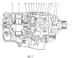
従来のインパクト工具を図2を用いて説明する。図2は蓄電池を動力源とする従来のインパクト工具本体の構造断面図である。一般的にインパクト工具本体を形成するハウジング6或いはハンマケース7内には、駆動源であるモータ8と、モータ8の出力軸であるピニオン9の回転動力を伝達する減速機構部と、減速機構部からの回転動力を伝達するスピンドル2と、スピンドル2に形成したカム溝に挿入されたスチールボール11を介して回転可能且つ回転軸方向に移動可能なハンマ12と、ハンマ12に設けた複数の爪部により打撃され回転する羽根部を有するアンビル1と、ハンマ12を前記アンビル1側に常に不勢するスプリング13とが収容されている。
A conventional impact tool will be described with reference to FIG. FIG. 2 is a structural sectional view of a conventional impact tool main body using a storage battery as a power source. Generally, in a
また、上記減速機構部は、ハウジング6内に回転止めを有し支持されている固定歯車支持具14、固定歯車15、遊星歯車10、スピンドル2を有し、且スピンドル2に支持される遊星歯車10の回転軸となるニードルピン16を有しており、更に遊星歯車10及びニードルピン16はスピンドル2の一部を成している。
The speed reduction mechanism unit includes a
また、上記スピンドル2の一端は軸受けにより軸支され且、他端は軸突起部を有し、メタル軸受け17により回転可能に軸支されているアンビル1の中心穴内に回転可能に軸支されている。
One end of the
先端工具4によって締め付けられるねじやボルト等に与えるパルス的な衝撃(インパクト)は、トリッガスイッチ19の操作によりモータ8に蓄電池5からの電力を供給し、モータ8を回転駆動させた後、このモータ8の回転動力をモータ8の先端に連結されているピニオン9を介して遊星歯車10に伝達し、遊星歯車10と固定歯車15の噛み合いによりピニオン9の回転動力をニードルピン16を介してスピンドル2に伝達し、スピンドル2のカム溝2aとハンマ12のカム溝12b間に配置されたスチールボール11を介して、スピンドル2の回転力をハンマ12に伝達し、ハンマ12とスピンドル2の遊星歯車10との間に配されているスプリング13によって前方に不勢されている。上記ハンマ12の爪部が回転によりアンビル1の羽根を打撃することにより発生する。
A pulse-like impact (impact) applied to a screw, bolt, or the like that is tightened by the tip tool 4 supplies electric power from the storage battery 5 to the
打撃後、ハンマ12の打撃エネルギーが減少しアンビル1のトルクが減少すると、ハンマ12はアンビル1から反発するため、ハンマ12はカム溝に沿って遊星歯車10方向に移動する。ハンマ12がストッパ18に突き当たる前に、ハンマ12はスプリング13の圧縮力で再びアンビル1方向にカム溝に沿って押し戻され、更にスピンドル2のカム溝とハンマ12のカム溝間に配置されたスチールボール11を介して、スピンドル2の回転によりハンマ12が加速される。ハンマ12がストッパ18までの間をカム溝に沿って往復する間にスピンドル2は回転し続けるため、ハンマ12の爪部はアンビル1の羽根部を乗り越え、再度ハンマ12の爪部がアンビル1の羽根部を打撃する場合、ハンマ12が180°回転した状態でアンビル1を打撃する。この様にハンマ12の軸方向移動と回転によりアンビル1への打撃を繰り返すことで、連続的に衝撃トルクを与えながらねじやボルトを締め付けている。
After the impact, when the impact energy of the
このように構成されたインパクト工具の用途は多岐に渡り、多くのユーザーに使用頂いており、特に軽負荷作業用に小型・軽量化の要望が強く求められている。 The impact tool constructed as described above has a wide variety of uses and is used by many users. In particular, there is a strong demand for reduction in size and weight for light load work.
前記のように構成された従来のインパクト工具は、減速機構部の一構成部品である固定歯車が、固定歯車支持具と固定歯車に分割されており、さらにハンマケース内に配設される配置になっているため部品点数が多く、寸法も大きくなってしまう。 In the conventional impact tool configured as described above, the fixed gear, which is one component of the speed reduction mechanism, is divided into a fixed gear support and a fixed gear, and further arranged in a hammer case. As a result, the number of parts is large and the dimensions are large.
本発明の目的は上記問題点を解消し、小型・軽量のインパクト工具を提供するものである。 The object of the present invention is to solve the above problems and provide a small and lightweight impact tool.
上記の目的は、モータと、モータを収納するハウジングと、前記モータに接続されるピニオン、前記ピニオンに噛合する遊星歯車、前記遊星歯車に噛合する固定歯車、から成る減速機構部と、減速機構部を介して駆動されるスピンドルと、スピンドルに接続される先端工具と、を有する電動工具において、ハウジング前記固定歯車を一体成形したことを特徴とすることにより達成することができる。 The above object is achieved by: a speed reduction mechanism portion including a motor, a housing for housing the motor, a pinion connected to the motor, a planetary gear meshing with the pinion, a fixed gear meshing with the planetary gear, and a speed reduction mechanism portion In the electric power tool having a spindle driven through a spindle and a tip tool connected to the spindle, the housing can be achieved by integrally forming the fixed gear.
2つの機能を有する部品を一つの部品で構成するため、部品点数を削減できることから、小型・軽量化された電動工具を提供することができる。 Since the component having two functions is configured by one component, the number of components can be reduced, and thus a small and lightweight electric tool can be provided.
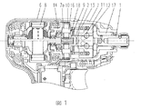
以下に本発明の実施例を図1を用いて説明する。蓄電池を動力源とするインパクト機構は、背景技術で説明した通りである。図1は本発明の実施形態を示すインパクト工具の側面断面図である。 An embodiment of the present invention will be described below with reference to FIG. The impact mechanism using the storage battery as the power source is as described in the background art. FIG. 1 is a side sectional view of an impact tool showing an embodiment of the present invention.
減速機構部および打撃機構部はハンマケース7内に収納されている。回転動力の伝達は、モータ軸に圧入されたピニオン9とスピンドル2に軸支されたニードルピン16を回転軸とする遊星歯車10が係合し、さらに遊星歯車10はハンマケース7に一体成形された固定歯車部7aと係合し、スピンドル2が回転可能となり、ハンマ12を介し、最終出力軸であるアンビル1に伝達される。
The speed reduction mechanism and the striking mechanism are housed in the
このように従来の技術に示した固定歯車10とハンマケース7を一体化し、歯車部7aを設けることにより小型化が図れ、部品点数の削減により軽量化も図ることが出来る。
Thus, the
1 アンビル、2 スピンドル、6 ハウジング、7 ハンマケース、7a 歯車部、8 モータ、9 ピニオン、10 遊星歯車、11 スチールボール、12 ハンマ、13 スプリング、14 固定歯車支持具、15 固定歯車、16 ニードルピン、17 メタル軸受け、18 ストッパ
DESCRIPTION OF
Claims (2)
モータを収納するハウジングと、
前記モータに接続されるピニオン、前記ピニオンに噛合する遊星歯車、前記遊星歯車に噛合する固定歯車、から成る減速機構部と、
減速機構部を介して駆動されるスピンドルと、
スピンドルに接続される先端工具と、を有する電動工具において、
ハウジングに前記固定歯車を一体成形したことを特徴とする電動工具。 A motor,
A housing for housing the motor;
A reduction mechanism comprising a pinion connected to the motor, a planetary gear meshing with the pinion, and a fixed gear meshing with the planetary gear;
A spindle driven via a speed reduction mechanism,
A power tool having a tip tool connected to the spindle;
An electric tool characterized in that the fixed gear is integrally formed in a housing.
前記スピンドルに延設されたアンビルと、
前記アンビルを前記スピンドルの回転方向に打撃し、前記先端工具を保持する打撃機構部と、
が収容されており、
前記ハウジングは、前記打撃機構部及び前記減速機構部を覆うハンマケースを有しており、
前記ハンマケースに前記固定歯車を一体成型したことを特徴とする請求項1記載の電動工具。 The housing includes
An anvil extending to the spindle;
A striking mechanism for striking the anvil in the rotational direction of the spindle and holding the tip tool;
Is housed,
The housing has a hammer case that covers the striking mechanism and the speed reduction mechanism,
The electric tool according to claim 1, wherein the fixed gear is formed integrally with the hammer case.
Priority Applications (1)
| Application Number | Priority Date | Filing Date | Title |
|---|---|---|---|
| JP2008199899A JP2010036282A (en) | 2008-08-01 | 2008-08-01 | Power tool |
Applications Claiming Priority (1)
| Application Number | Priority Date | Filing Date | Title |
|---|---|---|---|
| JP2008199899A JP2010036282A (en) | 2008-08-01 | 2008-08-01 | Power tool |
Publications (1)
| Publication Number | Publication Date |
|---|---|
| JP2010036282A true JP2010036282A (en) | 2010-02-18 |
Family
ID=42009358
Family Applications (1)
| Application Number | Title | Priority Date | Filing Date |
|---|---|---|---|
| JP2008199899A Pending JP2010036282A (en) | 2008-08-01 | 2008-08-01 | Power tool |
Country Status (1)
| Country | Link |
|---|---|
| JP (1) | JP2010036282A (en) |
Cited By (1)
| Publication number | Priority date | Publication date | Assignee | Title |
|---|---|---|---|---|
| JP2017213617A (en) * | 2016-05-30 | 2017-12-07 | 日立工機株式会社 | Electric tool |
Citations (2)
| Publication number | Priority date | Publication date | Assignee | Title |
|---|---|---|---|---|
| JPH10180645A (en) * | 1996-12-20 | 1998-07-07 | Tohnichi Mfg Co Ltd | Rechargeable torque wrench |
| JP2004249429A (en) * | 2003-02-21 | 2004-09-09 | Hitachi Koki Co Ltd | Impact tool |
-
2008
- 2008-08-01 JP JP2008199899A patent/JP2010036282A/en active Pending
Patent Citations (2)
| Publication number | Priority date | Publication date | Assignee | Title |
|---|---|---|---|---|
| JPH10180645A (en) * | 1996-12-20 | 1998-07-07 | Tohnichi Mfg Co Ltd | Rechargeable torque wrench |
| JP2004249429A (en) * | 2003-02-21 | 2004-09-09 | Hitachi Koki Co Ltd | Impact tool |
Cited By (1)
| Publication number | Priority date | Publication date | Assignee | Title |
|---|---|---|---|---|
| JP2017213617A (en) * | 2016-05-30 | 2017-12-07 | 日立工機株式会社 | Electric tool |
Similar Documents
| Publication | Publication Date | Title |
|---|---|---|
| US7048075B2 (en) | Power tool | |
| JP2018161731A (en) | Rotating hammer tool | |
| JP2010535642A5 (en) | ||
| CN102844154A (en) | Impact device | |
| EP2883657A2 (en) | Rotary impact tool | |
| JP2017159418A (en) | Impact rotary tool | |
| JP2016165782A (en) | Impact rotary tool | |
| JP6607502B2 (en) | Impact rotary tool | |
| JP4013782B2 (en) | Rotating hammer tool | |
| JP3716751B2 (en) | Electric tool | |
| JP2009172732A (en) | Impact rotary tool | |
| JP2018187700A (en) | Electric tool | |
| JP2010036282A (en) | Power tool | |
| JP2003181774A (en) | Impact tool | |
| JP2013022691A (en) | Impact rotary tool | |
| JP2018122393A (en) | Rotary impact tool | |
| JP2007030105A (en) | Impact tools | |
| WO2018061389A1 (en) | Rotary impact tool | |
| JP2005066728A (en) | Impact rotating tool | |
| JP3815686B2 (en) | Electric tool | |
| JP6719084B2 (en) | Rotary impact tool | |
| JP4399864B2 (en) | Electric tool | |
| JP4056041B2 (en) | Electric tool | |
| JP3982509B2 (en) | Portable tools | |
| JP4046464B2 (en) | Impact tools |
Legal Events
| Date | Code | Title | Description |
|---|---|---|---|
| A621 | Written request for application examination |
Free format text: JAPANESE INTERMEDIATE CODE: A621 Effective date: 20101228 |
|
| A131 | Notification of reasons for refusal |
Free format text: JAPANESE INTERMEDIATE CODE: A131 Effective date: 20120904 |
|
| A02 | Decision of refusal |
Free format text: JAPANESE INTERMEDIATE CODE: A02 Effective date: 20130122 |