JP6696427B2 - Phosphor wheel, light source device, and projection display device - Google Patents
Phosphor wheel, light source device, and projection display device Download PDFInfo
- Publication number
- JP6696427B2 JP6696427B2 JP2016552850A JP2016552850A JP6696427B2 JP 6696427 B2 JP6696427 B2 JP 6696427B2 JP 2016552850 A JP2016552850 A JP 2016552850A JP 2016552850 A JP2016552850 A JP 2016552850A JP 6696427 B2 JP6696427 B2 JP 6696427B2
- Authority
- JP
- Japan
- Prior art keywords
- substrate
- phosphor
- phosphor wheel
- light
- heat
- Prior art date
- Legal status (The legal status is an assumption and is not a legal conclusion. Google has not performed a legal analysis and makes no representation as to the accuracy of the status listed.)
- Active
Links
Images


Classifications
-
- G—PHYSICS
- G03—PHOTOGRAPHY; CINEMATOGRAPHY; ANALOGOUS TECHNIQUES USING WAVES OTHER THAN OPTICAL WAVES; ELECTROGRAPHY; HOLOGRAPHY
- G03B—APPARATUS OR ARRANGEMENTS FOR TAKING PHOTOGRAPHS OR FOR PROJECTING OR VIEWING THEM; APPARATUS OR ARRANGEMENTS EMPLOYING ANALOGOUS TECHNIQUES USING WAVES OTHER THAN OPTICAL WAVES; ACCESSORIES THEREFOR
- G03B21/00—Projectors or projection-type viewers; Accessories therefor
- G03B21/14—Details
- G03B21/16—Cooling; Preventing overheating
-
- C—CHEMISTRY; METALLURGY
- C09—DYES; PAINTS; POLISHES; NATURAL RESINS; ADHESIVES; COMPOSITIONS NOT OTHERWISE PROVIDED FOR; APPLICATIONS OF MATERIALS NOT OTHERWISE PROVIDED FOR
- C09K—MATERIALS FOR MISCELLANEOUS APPLICATIONS, NOT PROVIDED FOR ELSEWHERE
- C09K11/00—Luminescent, e.g. electroluminescent, chemiluminescent materials
- C09K11/08—Luminescent, e.g. electroluminescent, chemiluminescent materials containing inorganic luminescent materials
- C09K11/77—Luminescent, e.g. electroluminescent, chemiluminescent materials containing inorganic luminescent materials containing rare earth metals
- C09K11/7706—Aluminates
-
- F—MECHANICAL ENGINEERING; LIGHTING; HEATING; WEAPONS; BLASTING
- F21—LIGHTING
- F21V—FUNCTIONAL FEATURES OR DETAILS OF LIGHTING DEVICES OR SYSTEMS THEREOF; STRUCTURAL COMBINATIONS OF LIGHTING DEVICES WITH OTHER ARTICLES, NOT OTHERWISE PROVIDED FOR
- F21V14/00—Controlling the distribution of the light emitted by adjustment of elements
- F21V14/08—Controlling the distribution of the light emitted by adjustment of elements by movement of the screens or filters
-
- F—MECHANICAL ENGINEERING; LIGHTING; HEATING; WEAPONS; BLASTING
- F21—LIGHTING
- F21V—FUNCTIONAL FEATURES OR DETAILS OF LIGHTING DEVICES OR SYSTEMS THEREOF; STRUCTURAL COMBINATIONS OF LIGHTING DEVICES WITH OTHER ARTICLES, NOT OTHERWISE PROVIDED FOR
- F21V29/00—Protecting lighting devices from thermal damage; Cooling or heating arrangements specially adapted for lighting devices or systems
- F21V29/50—Cooling arrangements
- F21V29/70—Cooling arrangements characterised by passive heat-dissipating elements, e.g. heat-sinks
- F21V29/74—Cooling arrangements characterised by passive heat-dissipating elements, e.g. heat-sinks with fins or blades
- F21V29/76—Cooling arrangements characterised by passive heat-dissipating elements, e.g. heat-sinks with fins or blades with essentially identical parallel planar fins or blades, e.g. with comb-like cross-section
-
- F—MECHANICAL ENGINEERING; LIGHTING; HEATING; WEAPONS; BLASTING
- F21—LIGHTING
- F21V—FUNCTIONAL FEATURES OR DETAILS OF LIGHTING DEVICES OR SYSTEMS THEREOF; STRUCTURAL COMBINATIONS OF LIGHTING DEVICES WITH OTHER ARTICLES, NOT OTHERWISE PROVIDED FOR
- F21V9/00—Elements for modifying spectral properties, polarisation or intensity of the light emitted, e.g. filters
- F21V9/30—Elements containing photoluminescent material distinct from or spaced from the light source
-
- G—PHYSICS
- G02—OPTICS
- G02B—OPTICAL ELEMENTS, SYSTEMS OR APPARATUS
- G02B19/00—Condensers, e.g. light collectors or similar non-imaging optics
- G02B19/0004—Condensers, e.g. light collectors or similar non-imaging optics characterised by the optical means employed
- G02B19/0009—Condensers, e.g. light collectors or similar non-imaging optics characterised by the optical means employed having refractive surfaces only
- G02B19/0014—Condensers, e.g. light collectors or similar non-imaging optics characterised by the optical means employed having refractive surfaces only at least one surface having optical power
-
- G—PHYSICS
- G02—OPTICS
- G02B—OPTICAL ELEMENTS, SYSTEMS OR APPARATUS
- G02B26/00—Optical devices or arrangements for the control of light using movable or deformable optical elements
- G02B26/007—Optical devices or arrangements for the control of light using movable or deformable optical elements the movable or deformable optical element controlling the colour, i.e. a spectral characteristic, of the light
- G02B26/008—Optical devices or arrangements for the control of light using movable or deformable optical elements the movable or deformable optical element controlling the colour, i.e. a spectral characteristic, of the light in the form of devices for effecting sequential colour changes, e.g. colour wheels
-
- G—PHYSICS
- G03—PHOTOGRAPHY; CINEMATOGRAPHY; ANALOGOUS TECHNIQUES USING WAVES OTHER THAN OPTICAL WAVES; ELECTROGRAPHY; HOLOGRAPHY
- G03B—APPARATUS OR ARRANGEMENTS FOR TAKING PHOTOGRAPHS OR FOR PROJECTING OR VIEWING THEM; APPARATUS OR ARRANGEMENTS EMPLOYING ANALOGOUS TECHNIQUES USING WAVES OTHER THAN OPTICAL WAVES; ACCESSORIES THEREFOR
- G03B21/00—Projectors or projection-type viewers; Accessories therefor
- G03B21/14—Details
- G03B21/20—Lamp housings
- G03B21/2006—Lamp housings characterised by the light source
- G03B21/2033—LED or laser light sources
- G03B21/204—LED or laser light sources using secondary light emission, e.g. luminescence or fluorescence
-
- G—PHYSICS
- G03—PHOTOGRAPHY; CINEMATOGRAPHY; ANALOGOUS TECHNIQUES USING WAVES OTHER THAN OPTICAL WAVES; ELECTROGRAPHY; HOLOGRAPHY
- G03B—APPARATUS OR ARRANGEMENTS FOR TAKING PHOTOGRAPHS OR FOR PROJECTING OR VIEWING THEM; APPARATUS OR ARRANGEMENTS EMPLOYING ANALOGOUS TECHNIQUES USING WAVES OTHER THAN OPTICAL WAVES; ACCESSORIES THEREFOR
- G03B33/00—Colour photography, other than mere exposure or projection of a colour film
- G03B33/10—Simultaneous recording or projection
- G03B33/12—Simultaneous recording or projection using beam-splitting or beam-combining systems, e.g. dichroic mirrors
-
- H—ELECTRICITY
- H04—ELECTRIC COMMUNICATION TECHNIQUE
- H04N—PICTORIAL COMMUNICATION, e.g. TELEVISION
- H04N9/00—Details of colour television systems
- H04N9/12—Picture reproducers
- H04N9/31—Projection devices for colour picture display, e.g. using electronic spatial light modulators [ESLM]
- H04N9/3141—Constructional details thereof
- H04N9/3144—Cooling systems
-
- H—ELECTRICITY
- H04—ELECTRIC COMMUNICATION TECHNIQUE
- H04N—PICTORIAL COMMUNICATION, e.g. TELEVISION
- H04N9/00—Details of colour television systems
- H04N9/12—Picture reproducers
- H04N9/31—Projection devices for colour picture display, e.g. using electronic spatial light modulators [ESLM]
- H04N9/3141—Constructional details thereof
- H04N9/315—Modulator illumination systems
- H04N9/3158—Modulator illumination systems for controlling the spectrum
-
- H—ELECTRICITY
- H04—ELECTRIC COMMUNICATION TECHNIQUE
- H04N—PICTORIAL COMMUNICATION, e.g. TELEVISION
- H04N9/00—Details of colour television systems
- H04N9/12—Picture reproducers
- H04N9/31—Projection devices for colour picture display, e.g. using electronic spatial light modulators [ESLM]
- H04N9/3141—Constructional details thereof
- H04N9/315—Modulator illumination systems
- H04N9/3161—Modulator illumination systems using laser light sources
-
- F—MECHANICAL ENGINEERING; LIGHTING; HEATING; WEAPONS; BLASTING
- F21—LIGHTING
- F21Y—INDEXING SCHEME ASSOCIATED WITH SUBCLASSES F21K, F21L, F21S and F21V, RELATING TO THE FORM OR THE KIND OF THE LIGHT SOURCES OR OF THE COLOUR OF THE LIGHT EMITTED
- F21Y2115/00—Light-generating elements of semiconductor light sources
- F21Y2115/30—Semiconductor lasers
-
- G—PHYSICS
- G03—PHOTOGRAPHY; CINEMATOGRAPHY; ANALOGOUS TECHNIQUES USING WAVES OTHER THAN OPTICAL WAVES; ELECTROGRAPHY; HOLOGRAPHY
- G03B—APPARATUS OR ARRANGEMENTS FOR TAKING PHOTOGRAPHS OR FOR PROJECTING OR VIEWING THEM; APPARATUS OR ARRANGEMENTS EMPLOYING ANALOGOUS TECHNIQUES USING WAVES OTHER THAN OPTICAL WAVES; ACCESSORIES THEREFOR
- G03B21/00—Projectors or projection-type viewers; Accessories therefor
- G03B21/005—Projectors using an electronic spatial light modulator but not peculiar thereto
- G03B21/006—Projectors using an electronic spatial light modulator but not peculiar thereto using LCD's
Description
本開示は、蛍光体ホイール及び光源装置並びに投射型表示装置に関する。 The present disclosure relates to a phosphor wheel, a light source device, and a projection display device.
プロジェクタ等の投射型表示装置に用いられる光源として、明るさやコストパフォーマンスの観点から超高圧水銀ランプが主として用いられているが、長寿命性、高機能付加等の観点から、長寿命であり色域の広い固体光源が注目されている。固体光源は、半導体のp/n接合による発光現象を用いた光源であり、LEDやレーザ(LD)等に代表される。近年では、特定の波長域の光を照射すると当該光とは異なる波長域の光を発光する蛍光体材料に対して固体光源により光を照射し、蛍光発光した光を利用する光源装置がプロジェクタ等に利用されている。 Ultra-high pressure mercury lamps are mainly used as the light source for projection type display devices such as projectors from the viewpoint of brightness and cost performance, but they have a long life and color gamut from the viewpoint of long life and addition of high functionality. A wide range of solid-state light sources are attracting attention. A solid-state light source is a light source that uses a light emitting phenomenon due to a semiconductor p / n junction, and is represented by an LED, a laser (LD), or the like. In recent years, a light source device that emits light from a solid-state light source to a phosphor material that emits light in a wavelength range different from that of the light when the light in a specific wavelength range is emitted, and a light source device that uses the fluorescence emitted is a projector or the like. Is used for.
かかる光源装置は、蛍光体層が表面に形成された蛍光体ホイールと、励起光を出射する固体光源とを備える。蛍光体の発光には輝度飽和や温度消光という現象が存在する。これは、励起光の出力を高くした場合、蛍光体での変換損失の一部が熱に変わって蛍光体が発熱し、蛍光発光の効率が下がってしまうというものである。蛍光変換効率が低い状態では、効率のよい明るい光源装置は実現できない。そのため、蛍光体ホイールに放熱板を取り付けて、放熱効率を向上させる技術が提案されている。 Such a light source device includes a phosphor wheel having a phosphor layer formed on its surface, and a solid-state light source that emits excitation light. There are phenomena such as brightness saturation and temperature quenching in the light emission of the phosphor. This is because when the output of the excitation light is increased, a part of the conversion loss in the phosphor is converted into heat and the phosphor heats up, resulting in a decrease in the efficiency of fluorescence emission. If the fluorescence conversion efficiency is low, an efficient bright light source device cannot be realized. Therefore, a technique has been proposed in which a heat dissipation plate is attached to the phosphor wheel to improve heat dissipation efficiency.
例えば、特許文献1には、赤用、緑用、青用それぞれの蛍光体領域が形成され、励起光を受けて赤色光、緑色光、青色光を蛍光として射出するカラーホイールにおいて、励起光が入射する面と反対側の面に放熱部を形成する技術が開示されている。また、特許文献2には、基板の表面に塗布された蛍光体を透過する光の光路を避けるように、蛍光体よりも半径方向に内側及び外側の少なくとも一方に放熱板を貼り付けた蛍光体ホイールが開示されている。 For example, in
しかしながら、特許文献1に記載の放熱部は、基板面に対して直交する方向に立ち上げられたフィンにより構成されており、カラーホイールの回転時に空気抵抗を受けて風損が大きくなりやすい。そのため、特許文献1に記載のカラーホイールは、カラーホイールを回転駆動するモータの消費電力が大きくなるおそれがある。また、特許文献1に記載のカラーホイールは、回転数を上げた場合に、フィンが受ける空気抵抗により騒音が大きくなるおそれがある。 However, the heat dissipation portion described in
また、特許文献2に記載の蛍光体ホイールは、基板の一方の面に、蛍光体に接するように放熱板を貼り付けるものであり、放熱板が受ける空気抵抗は小さくなるものの、放熱板の表面積は限定的なものである。 Further, the phosphor wheel described in
そこで、本開示では、蛍光体ホイールの空気抵抗や騒音を抑えつつ蛍光体ホイールからの放熱効率を向上させることが可能な、新規かつ改良された蛍光体ホイール及び光源装置並びに投射型表示装置を提案する。 Therefore, the present disclosure proposes a new and improved phosphor wheel, a light source device, and a projection display device capable of improving the heat radiation efficiency from the phosphor wheel while suppressing the air resistance and noise of the phosphor wheel. To do.
本開示によれば、円盤状の基板と、前記基板上に形成された蛍光体層と、前記基板の面に対して直交する方向に見たときに互いに重なる複数の放熱フィンと、を備える、蛍光体ホイールが提供される。 According to the present disclosure, a disk-shaped substrate, a phosphor layer formed on the substrate, and a plurality of heat radiation fins that overlap each other when viewed in a direction orthogonal to the surface of the substrate, A phosphor wheel is provided.
また、本開示によれば、第1の波長を有する励起光を出射する固体光源と、円盤状の基板、前記基板上に形成され前記励起光により励起されて前記第1の波長と異なる第2の波長を有する光を発光するとともに前記励起光の一部を透過する蛍光体層、及び、前記基板の面に対して直交する方向に見たときに互いに重なる複数の放熱フィン、を備える蛍光体ホイールと、前記蛍光体ホイールを前記基板の面に平行な面内で回転駆動するモータと、を備える、光源装置が提供される。 Further, according to the present disclosure, a solid-state light source that emits excitation light having a first wavelength, a disc-shaped substrate, and a second substrate that is formed on the substrate and is excited by the excitation light and that is different from the first wavelength A phosphor layer that emits light having a wavelength of 5 and transmits a part of the excitation light, and a plurality of radiation fins that overlap each other when viewed in a direction orthogonal to the surface of the substrate. There is provided a light source device including a wheel and a motor that rotationally drives the phosphor wheel in a plane parallel to the surface of the substrate.
また、本開示によれば、光源装置と、入射された光を変調し合成する光変調合成系と、前記光源装置から出射された光を前記光変調合成系へ導く照明光学系と、前記光変調合成系から出射された画像を投射する投射光学系と、からなり、前記光源装置は、第1の波長を有する励起光を出射する固体光源と、円盤状の基板、前記基板上に形成され前記励起光により励起されて前記第1の波長と異なる第2の波長を有する光を発光するとともに前記励起光の一部を透過する蛍光体層、及び、前記基板の面に対して直交する方向に見たときに互いに重なる複数の放熱フィン、を備える蛍光体ホイールと、前記蛍光体ホイールを前記基板の面に平行な面内で回転駆動するモータと、を備える、投射型表示装置が提供される。 Further, according to the present disclosure, a light source device, a light modulation combining system that modulates and combines incident light, an illumination optical system that guides light emitted from the light source device to the light modulation combining system, and the light A projection optical system for projecting an image emitted from a modulation / combination system, and the light source device includes a solid-state light source for emitting excitation light having a first wavelength, a disc-shaped substrate, and the substrate formed on the substrate. A phosphor layer that is excited by the excitation light to emit light having a second wavelength different from the first wavelength and that transmits part of the excitation light, and a direction orthogonal to the surface of the substrate. A projection-type display device is provided, which includes: a phosphor wheel including a plurality of heat-dissipating fins that overlap each other when viewed from above, and a motor that rotationally drives the phosphor wheel in a plane parallel to the surface of the substrate. It
以上説明したように本開示によれば、蛍光体ホイールの空気抵抗や騒音を抑えつつ、蛍光体ホイールからの放熱効率を向上させることが可能な蛍光体ホイール及び光源装置並びに投射型表示装置を実現することができる。
なお、上記の効果は必ずしも限定的なものではなく、上記の効果とともに、または上記の効果に代えて、本明細書に示されたいずれかの効果、または本明細書から把握され得る他の効果が奏されてもよい。As described above, according to the present disclosure, a phosphor wheel, a light source device, and a projection display device capable of improving the heat dissipation efficiency from the phosphor wheel while suppressing the air resistance and noise of the phosphor wheel are realized. can do.
Note that the above effects are not necessarily limited, and in addition to or in place of the above effects, any of the effects shown in this specification, or other effects that can be grasped from this specification. May be played.
以下に添付図面を参照しながら、本開示の好適な実施の形態について詳細に説明する。なお、本明細書及び図面において、実質的に同一の機能構成を有する構成要素については、同一の符号を付することにより重複説明を省略する。 Hereinafter, preferred embodiments of the present disclosure will be described in detail with reference to the accompanying drawings. In the present specification and the drawings, constituent elements having substantially the same functional configuration are designated by the same reference numerals, and a duplicate description will be omitted.
説明は以下の順序で行うものとする。
1.第1の実施の形態(基板に放熱構造部が接合された例)
1.1.投射型表示装置の構成例
1.2.光源装置の構成例
1.3.蛍光体ホイールの構成例
1.4.冷却風の供給経路の構成例
1.5.変形例
2.第2の実施の形態(放熱フィンが基板を兼ねる例)
3.第3の実施の形態(放熱フィンを介してモータに取り付けられる例)
4.第4の実施の形態(応力緩和領域を設けた例)
5.第5の実施の形態(基板の両面に放熱フィンを有する例)
5.1.光源装置の構成例
5.2.蛍光体ホイールの構成例
6.第6の実施の形態(放熱フィンを炭素繊維混合成形品により構成した例)
7.第7の実施の形態(周縁部に透過型基板が接合された例)The description will be given in the following order.
1. First embodiment (example in which a heat dissipation structure is bonded to a substrate)
1.1. Configuration example of projection display device 1.2. Example of configuration of light source device 1.3. Configuration example of phosphor wheel 1.4. Configuration example of cooling air supply path 1.5.
3. Third embodiment (an example of being attached to a motor through a radiation fin)
4. Fourth embodiment (example in which a stress relaxation region is provided)
5. Fifth embodiment (example having radiation fins on both sides of the substrate)
5.1. Configuration example of light source device 5.2. Configuration example of phosphor wheel 6. Sixth embodiment (example in which the heat radiation fin is made of a carbon fiber mixed molded product)
7. Seventh embodiment (example in which a transmissive substrate is bonded to the peripheral edge)
<1.第1の実施の形態>
[1.1.投射型表示装置の構成例]
まず、図1を参照して、本開示の第1の実施の形態にかかる光源装置10を備える投射型表示装置1の構成例について説明する。図1は、本実施形態にかかる光源装置10を備えた投射型表示装置1の概略構成を示す図である。<1. First Embodiment>
[1.1. Configuration example of projection display device]
First, with reference to FIG. 1, a configuration example of a
本実施形態にかかる投射型表示装置1は、光源から出射された光を集め、画像を表示させるデバイスを通して投影レンズから光を出射し、スクリーンS等の表示面に画像を投影するプロジェクタである。図1に示す投射型表示装置1は、マイクロディスプレイとして3LCDを用いたプロジェクタの構成例である。 The
光源装置10から出射された光は、表示画像の端部まで明るさを維持するように第1レンズアレイ2aおよび第2レンズアレイ2bからなるインテグレータレンズ2を通過した後、偏光変換素子3a、集光レンズ3bを通過し、波長域毎に分離される。集光レンズ3bを通過した光は、赤色の波長域の光のみを反射し、その他の波長域の光を通過させる第1反射ダイクロイックミラー4aに入射する。これにより、赤色の波長域の光は第1反射ダイクロイックミラー4aにより反射されて反射ミラー5a側へ進行する。赤色の波長域の光は、反射ミラー5aによりさらに反射されて赤色用液晶パネル6aに入射する。 The light emitted from the
第1反射ダイクロイックミラー4aを通過したその他の波長域の光は第2反射ダイクロイックミラー4bへ入射する。第2反射ダイクロイックミラー4bは、緑色の波長域の光のみを反射し、その他の波長域の光、すなわち青色の波長域の光を通過させる。第2反射ダイクロイックミラー4bにより反射された緑色の波長域の光は緑色用液晶パネル6bに入射する。また、第2反射ダイクロイックミラー4bを通過した青色の波長域の光は、反射ミラー5b、5cにより反射された後、青色用液晶パネル6cへ入射する。 The light in the other wavelength regions that has passed through the first reflective
各色用の液晶パネル6a〜6cは、入力画像信号に応じてそれぞれに入射した光を変調し、RGBに対応する画像の信号光を生成する。液晶パネル6a〜6cには、例えば高温ポリシリコンTFTを用いた透過型液晶素子を使用してもよい。各液晶パネル6a〜6cにより変調された信号光は、ダイクロイックプリズム7に入射され、合成される。ダイクロイックプリズム7は、赤色の信号光および青色の信号光を反射し、緑色の信号光を透過させるように、4つの三角柱を組み合わせた直方体に形成されている。ダイクロイックプリズム7により合成された各色の信号光は投射レンズ8へ入射されて、スクリーンS等の表示面に画像として投影される。 The
投射型表示装置1において、液晶パネル6a〜6cおよびダイクロイックプリズム7は入射された光を変調して合成する光変調合成系として機能するものである。また、インテグレータレンズ2、偏光変換素子3a、集光レンズ3b、反射ダイクロイックミラー4a、4b、反射ミラー5a〜5cは、光変調合成系を構成する液晶パネル6a〜6cに光源装置10からの光を導く照明光学系として機能するものである。そして、および投射レンズ8は、ダイクロイックプリズム7から出射された画像を投射する投射光学系として機能するものである。 In the projection
[1.2.光源装置の構成例]
次に、投射型表示装置1に備えられた光源装置10の構成例について説明する。図2は、本実施形態にかかる光源装置10の概略構成例を示す図である。かかる光源装置10は、青色波長域のレーザ光と、当該レーザ光によって励起される蛍光体材料から生じる赤色波長域から緑色波長域の光、すなわち黄色光と、を合成して白色光を出射する光源装置である。[1.2. Configuration example of light source device]
Next, a configuration example of the
光源装置10は、固体光源32と、ダイクロイックミラー34と、集光レンズ38と、蛍光体ホイール100と、モータ40とを備えている。固体光源32は、蛍光体材料に対する照射用(励起用)の励起光源であり、所定波長域(第1の波長)の光を射出する固定発光素子により構成される。固体光源32は、例えば、400〜500nmの波長域内に発光強度のピーク波長を有する青色レーザ光(励起光)BLを発振可能な青色レーザとすることができる。固体光源32は、蛍光体ホイール100からの出射光の光路の延長上に配置される。 The
また、青色レーザにより固体光源32を構成する場合、一つの青色レーザで所定出力の励起光BLを得るようにしてもよいが、複数の青色レーザからの出射光を合波して所定出力の励起光BLを得るようにしてもよい。図2の例は、三つの青色レーザからの出射光を合波する。 Further, when the solid-
ダイクロイックミラー34は、固体光源32と集光レンズ38との間の光路上に、光路に対して約45°に傾けて配置される。固体光源32から出射された励起光BLは、ダイクロイックミラー34の第1の面34aに入射する。ダイクロイックミラー34は、第1の面34aから入射する励起光BLを透過させ、集光レンズ38を介して蛍光体ホイール100に射出する。また、ダイクロイックミラー34は、当該ダイクロイックミラー34及び集光レンズ38を介して固体光源32と対向して配置された蛍光体層130による蛍光発光光及び励起光BLの反射光を第2の面34bで反射する。 The
例えば、固体光源32から出射する励起光BLが直線偏光光とされ、蛍光体層130から射出される蛍光発光光及び反射光の偏光が回転させられるか又は乱されるようにする。これにより、ダイクロイックミラー34において励起光BLを透過させつつ、蛍光発光光及び反射光を反射させることができる。なお、固体光源32から入射される励起光BLと、蛍光体ホイール100からの蛍光発光光及び反射光とを分離する光学系の構成としては、ダイクロイックミラー34に限られず、任意の光学系を用いることができる。 For example, the excitation light BL emitted from the solid-
集光レンズ38は、蛍光体ホイール100からの蛍光発光光及び反射光の光路上に配置されている。集光レンズ38は、ダイクロイックミラー34を透過した励起光BLを所定のスポット径に集光し、当該集光した集光光を蛍光体ホイール100に射出する。また、集光レンズ38は、蛍光体ホイール100からの蛍光発光光及び反射光を平行光に変換し、その平行光をダイクロイックミラー34に射出する。なお、集光レンズ38は、例えば、一枚のコリメートレンズにより構成してもよく、複数のレンズを用いた構成としてもよい。 The
蛍光体ホイール100は、集光レンズ38を介して入射された励起光BLの一部を吸収し、所定波長域(第2の波長)の光を発光するとともに、残りの励起光BLを反射する。蛍光体ホイール100は、蛍光発光光及び反射した励起光を集光レンズ38に射出する。本実施形態では、光源装置10は、白色光LWを出射し、蛍光体ホイール100は、励起光BLにより、緑色光及び赤色光を含む波長域(約480〜680nm)の光を発光する。蛍光体ホイール100は、緑色光及び赤色光を含む二つの波長域の蛍光発光光と、蛍光体ホイール100で反射する励起光(青色光)とを合波して、白色光を集光レンズ38に射出する。なお、蛍光体ホイール100の構成については後で詳しく説明する。 The
モータ40は、蛍光体ホイール100を所定の回転数で回転駆動する。このとき、モータ40は、励起光BLの照射方向に直交する面(基板面)内で蛍光体ホイール100が回転するように、基板面に直交する回転軸Aを中心に蛍光体ホイール100を回転駆動する。したがって、蛍光体ホイール100に形成された蛍光体層130における励起光BLの照射位置が、励起光BLの照射方向に直交する面内において回転数に対応した速度で時間的に変化する。 The
このように、蛍光体ホイール100をモータ40で回転駆動して蛍光体ホイール100における励起光BLの照射位置を時間とともに変化させることにより、照射位置の温度上昇を抑制することができる。これにより、蛍光体層130の蛍光変換効率の低下を抑えることができる。また、蛍光体原子が励起光BLを吸収して発光するまでに僅かながら時間がかかるため、その励起期間中に、次の励起光BLが蛍光体原子に照射されても、その励起光BLに対しては発光しない。しかしながら、蛍光体ホイール100における励起光BLの照射位置を時間とともに変化させることにより、励起光BLの照射位置には、励起されていない蛍光体原子が次々と配置されることになる。これにより、蛍光体層130をより効率よく発光させることができる。 In this way, by rotating the
[1.3.蛍光体ホイールの構成例]
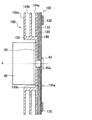
次に、本実施形態にかかる蛍光体ホイール100の構成例について説明する。図2には、蛍光体ホイール100を、回転軸Aを含む面で切断した断面図が示されている。また、図3は、蛍光体ホイール100を基板120側から見た斜視図であり、図4は、蛍光体ホイール100を構成する放熱構造部150を、基板120側とは反対側から見た斜視図である。蛍光体ホイール100は、円盤状の基板120と、基板120の一方(励起光BLの入射側)の面120a上に形成された蛍光体層130と、基板120及び蛍光体層130の間に設けられた図示しない光反射膜110と、複数の放熱フィン154a〜154cを有する放熱構造部150とを備える。[1.3. Example of phosphor wheel configuration]
Next, a configuration example of the
(1.3.1.基板)
基板120は、例えば、アルミニウムやモリブデン等の金属や合金等の非透光性材料を用いて形成される。本実施形態にかかる蛍光体ホイール100は、蛍光発光光及び励起光BLを反射する反射型のものであり、所定の強度を有する材料であれば非透光性材料又は透光性材料にかかわらず任意の材料で形成することができる。ただし、本実施形態にかかる蛍光体ホイール100は反射型のものであることから、光反射率を向上させるために金属材料からなる基板120であることが好ましい。特に、アルミニウムやモリブデン等の金属材料からなる基板120であれば、高い伝熱性を得ることもできる。(1.3.1. Substrate)
The
基板120は、中心部分でモータ40の出力軸40aに取り付けられ、固定ハブ42により出力軸40aに固定される。基板120の厚さ等の寸法は、例えば、必要とされる強度、重量、加工性等を考慮して、適宜設定される。本実施形態では、一例として、厚さが0.5mm、直径が70mmのモリブデン製の基板120が用いられている。ただし、放熱効率が高い蛍光体ホイール100であれば、基板120の直径が小さい場合であっても蛍光体層130の温度上昇を抑えることができるために、放熱効率等を考慮して基板120の直径を設定することができる。 The
(1.3.2.光反射膜)
光反射膜110は、基板120の一方の面120a上で、少なくとも基板120と蛍光体層130との間に設けられる。光反射膜110は、入射される光の波長及び入射角にかかわらず、すべての光を反射する。したがって、光反射膜110は、蛍光体層130での励起による蛍光発光光を集光レンズ38側に反射するだけでなく、蛍光体層130を透過した励起光(青色光)BLの一部も集光レンズ38側に反射する。本実施形態にかかる蛍光体ホイール100は、モリブデン製の基板120上に、例えばアルミニウム等の金属膜や光反射性の樹脂膜からなる光反射膜110が設けられている。
(1.3.2. Light reflection film)
The
かかる光反射膜110は、基板120の一方の面120a上で、少なくとも蛍光体層130の配置位置に対応するように、中央に開口を有する円形状に形成することができる。この場合、光反射膜110は、基板120と同心円となるように基板120上に配置される。光反射膜110の径方向の幅は、少なくとも、集光レンズ38により集光される励起光(集光光)BLのスポットサイズよりも大きくなるように設定される。ただし、基板120をアルミニウム等の金属又は合金により構成する場合には、蛍光体層130を形成する面120aを鏡面仕上げすることにより、当該面120aに光反射膜としての機能を持たせてもよい。 The
(1.3.3.蛍光体層)
蛍光体層130は、層状の蛍光体で形成され、励起光BLが入射された際に、励起光BLの一部を吸収して所定波長域(第2の波長)の光を発光する。また、蛍光体層130は、吸収されない残りの励起光BLのうち、一部の励起光BLを透過させ、かつ、残りの励起光BLを拡散(反射)する。蛍光体層130は、蛍光材料とバインダとを混合した蛍光剤を光反射膜110上に塗布することにより形成することができる。蛍光体層130は、水ガラス(Na2SiO3)を用いて形成してもよい。蛍光体層130は基板120の全面に渡って塗布されていてもよく、また、励起光が照射される周縁部にのみ塗布されていてもよい。(1.3. 3. Phosphor layer)
The
本実施形態では、蛍光体層130は、例えば、YAG(Yttrium Aluminum Garnet)系の蛍光材料等により形成される。これにより、光反射膜110及び蛍光体層130で反射された励起光BLの一部と、蛍光体層130で発光した蛍光発光光とを合波して白色光を生成することができる。YAGにより蛍光体層130を形成した場合、青色の励起光BLが入射されると、蛍光体層130は480〜680nmの波長域の光を発光する。当該波長域の光は赤色光及び青色光を含み、これらの光が合波されて黄色光として発光される。 In the present embodiment, the
また、蛍光体層130における発光量、及び、励起光の透過量や反射量の割合は、例えば蛍光体層130の厚さや蛍光体密度等により調整することができる。すなわち、本実施形態では、光源装置10から出射される光が白色光となるように、蛍光体層130の厚さや蛍光体密度等が調整される。本実施形態では、蛍光体層130の厚さは0.5mmとなっている。 Further, the emission amount in the
かかる蛍光体層130は、励起光BLにより励起されて発光する際に発熱するが、蛍光体層130の熱伝導率は比較的小さいため、主に基板120側に熱が伝達される。そのため、本実施形態にかかる蛍光体ホイール100は、蛍光体層130の熱を基板120及び接合層140を介して放熱構造部150に伝達して、放熱させる構成となっている。 The
(1.3.4.接合層)
接合層140は、熱伝導性の接着剤又は熱伝導性の粘着シートからなり、蛍光体層130が形成された面120aとは反対側の面120bにおいて、基板120に対して放熱構造部150を接合する機能を有する。接合層140が熱伝導性を有することによって、基板120が有する熱を効率的に放熱構造部150に伝達することができる。本実施形態では、基板120がモリブデンからなり、放熱構造部150がアルミニウムからなり、両者の熱膨張率が異なるために、接合層140が弾性を有することが好ましい。(1.3.4. Bonding layer)
The
ただし、例えば、基板120及び放熱構造部150がともにアルミニウムにより形成され、基板120と放熱構造部150との熱膨張率が略一致する場合には、熱伝導性を有する接合層140であれば、使用可能な材料は限定されない。 However, for example, when the
また、接合層140の厚さが薄いと放熱構造部150が基板120から剥がれやすくなる一方、接合層140の厚さが厚いと熱伝導性が低下するおそれがある。したがって、接合層140の厚さを0.1〜0.5mmの範囲内の値とすることが好ましく、0.2〜0.4mmの範囲内の値とすることがより好ましい。本実施形態では、熱伝導性を有するシリコン系の接着剤が用いられ、接合層140の厚さが0.3mmとなっている。 Further, when the thickness of the
(1.3.5.放熱構造部)
放熱構造部150は、蛍光体層130が形成された基板120の面120aとは反対側の面120bに接合され、蛍光体ホイール100から放熱する機能を有する。本実施形態にかかる蛍光体ホイール100は反射型のものであり、放熱構造部150は、基板120の面120bの全体に対して接合されている。(1.3.5. Heat dissipation structure)
The
本実施形態にかかる蛍光体ホイール100の放熱構造部150は、基板120の面120aに直交する方向に見たときに互いに重なる複数の放熱フィン154a,154b,154cを有する。放熱構造部150は、三つの放熱フィン154a,154b,154cを有しているが、放熱フィンの数はこれに限られない。ただし、放熱構造部150の重量が大きくなると、モータ40の消費電力が大きくなることから、放熱効率と全体の重量とを考慮して放熱フィンの数が設定される。 The
複数の放熱フィン154a〜154cはいずれも円盤状の外形を有し、基板120と同心円状に設けられている。また、複数の放熱フィン154a〜154cはいずれも互いに平行に、かつ、基板120に平行に設けられている。複数の放熱フィン154a〜154cのうちの一つの放熱フィン154aは、基板120の面120bに対して直交する方向に延在する立上部152を有している。その他の放熱フィン154b,154cは、立上部152から延びて形成されている。複数の放熱フィン154a〜154cの間に形成されるそれぞれの間隙は、蛍光体ホイール100の外周方向に開放されている。 Each of the plurality of
立上部152は円筒形状を有し、立上部152の内部にはモータ40が配置される。立上部152は、基板120の面120bに対して直交する方向に延在するものに限られない。面120bから離れるにしたがって、直径が拡大又は縮小するテーパ形状の立上部としてもよい。 The rising
複数の放熱フィン154a〜154cのうち、基板120に接着される放熱フィン154aの形状は基板120の形状に略一致し、放熱フィン154aは、基板120の面120bの全領域に対して接合層140により接合されている。かかる放熱フィン154aの半径方向の中央部から立上部152が立ち上げられている。また、他の放熱フィン154b,154cは、立上部152よりも径方向外側に配置され、内縁部で立上部152に連結されている。放熱フィン154b,154cの外縁も基板120の外縁に略一致している。 Of the plurality of
本実施形態にかかる放熱構造部150は、軽量かつ低コストで成形可能な、熱伝導率の高いアルミニウムや銅を用いて成形することができる。本実施形態にかかる放熱構造部150は、複数の放熱フィン154a〜154c及び立上部152を切削加工により一体成形した加工品からなる。したがって、連結部分における伝熱効率の低下がなく、また、連結部分からの破損のおそれもない。ただし、アルミニウム板等の金属板を加工して得られた複数の放熱フィン及び立上部を接合して、放熱構造部150を形成してもよい。 The
放熱構造部150の厚さは、成形性や強度等を考慮して設定される。本実施形態では、切削加工により放熱構造部150が成形されており、複数の放熱フィン154a〜154c及び立上部152の厚さが0.5mmとなっている。また、複数の放熱フィン154a〜154cの直径や、放熱フィン154a〜154c間の間隙の大きさについても、重量や放熱効率等を考慮して設定される。ただし、放熱構造部150は、少なくとも、基板120の面120a上に形成された蛍光体層130の背面側に接合されるようにすることが好ましい。このようにすれば、蛍光体層130が有する熱を効率的に放熱構造部150に伝達して、放熱させることができる。 The thickness of the
このように、複数の放熱フィン154a〜154cを有する放熱構造部150とすることにより、放熱構造部150の表面積を大きくすることができる。そして、かかる放熱構造部150を、熱伝導性の接合層140を介して基板120に接合することにより、基板120から効率的に放熱させることができる。したがって、蛍光体層130の温度上昇を防ぐことができる。その結果、蛍光体層130の蛍光変換効率を高く維持することができるとともに、蛍光発光光の波長(第2の波長)を安定させることができる。 As described above, the surface area of the
また、基板120と放熱構造部150とが別体であることにより、既存の蛍光体ホイール基板に放熱構造部150を接合することで、放熱効率を向上させた蛍光体ホイール100を得ることができる。すなわち、円盤状の基板120に光反射膜110を形成し、さらに蛍光材料を塗布して蛍光体層130を形成する既存の行程を変更することなく、蛍光体ホイール100を得ることができる。 Further, since the
また、複数の放熱フィン154a〜154cが、基板120に平行に設けられているために、蛍光体ホイール100が回転する際に、放熱フィン154a〜154cが空気抵抗を受けにくくなっている。したがって、蛍光体ホイール100の回転による騒音を抑えることができるとともに、モータ40の消費電力の増加が抑えることができる。ただし、放熱フィン154a〜154cが空気抵抗を受けにくくする構成は、放熱フィン154a〜154cを基板120に平行に配置する例に限られない。例えば、回転軸Aを含む任意の断面を見たときに、それぞれの放熱フィン154a〜154cと基板120との成す角度が一定となるように放熱フィン154a〜154cを設けることにより、放熱フィン154a〜154cが受ける空気抵抗を小さくすることができる。 Further, since the plurality of
[1.4.冷却風の供給経路の構成例]
本実施形態にかかる蛍光体ホイール100では、複数の放熱フィン154a〜154cの間に形成された間隙が、蛍光体ホイール100の外周方向に開放されている。したがって、放熱効率を向上させるために、冷却風が、複数の放熱フィン154a〜154cの間の間隙に導入されるようにしてもよい。[1.4. Configuration example of cooling air supply path]
In the
図5は、蛍光体ホイール100が送風ダクト80内に配置された様子を示す。蛍光体ホイール100は、基板120の面120aが送風ダクト80の配設方向に沿うように送風ダクト80内に配置される。このとき、蛍光体層130に対する励起光BLの照射位置は冷却風の流れの上流側(図5の下方側)に位置している。当該照射位置に対応して、送風ダクト80には開口部80aが設けられ、かかる開口部80aに対応して、図示しない集光レンズ等が配置される。 FIG. 5 shows a state in which the
このように蛍光体ホイール100を送風ダクト80内に配置することにより、冷却ファン等により送風される冷却風を、励起光BLの照射位置に対応する領域の複数の放熱フィン154a〜154cの間の間隙に供給することができる。これにより、蛍光体層130のうち、発熱しやすい照射位置に対応する領域の放熱フィン154a〜154cに対して冷却風が供給されるようになる。したがって、蛍光体層130が発する熱を効率的に放熱させて、蛍光体層130の温度上昇を抑えることができる。 By disposing the
[1.5.変形例]
次に、本実施形態にかかる蛍光体ホイール100の変形例について説明する。[1.5. Modification]
Next, a modified example of the
(1.5.1.変形例1)
図6は、本実施形態の変形例1を示している。図6は、変形例1にかかる蛍光体ホイール100Aを、回転軸Aを含む面で切断した断面図を示している。かかる蛍光体ホイール100Aは、基板120の面120bに接合された放熱構造部150の立上部152の立ち上がり位置が、蛍光体層130の形成位置に対応している。かかる蛍光体ホイール100Aは、励起光BLの照射位置が、以下の関係を充足する位置に設定されている。
D/2<R
R:基板の中心(回転軸A)から照射位置までの距離
D:立上部の立ち上がり部分の直径(1.5.1. Modification 1)
FIG. 6 shows a first modification of the present embodiment. FIG. 6 is a cross-sectional view of the
D / 2 <R
R: Distance from the center of the substrate (rotation axis A) to the irradiation position D: Diameter of the rising part of the rising part
また、励起光BLの照射位置は、上記のD/2<Rの条件を満たすとともに、さらに、以下の関係を充足する位置に設定されてもよい。
0.4≦S/SA≦0.6
SA:蛍光体ホイールの表面のうちの空気に接する全表面積
S:蛍光体層が形成された基板及び基板に接合された放熱フィンのうち励起光の照射位置よりも外周側の領域(図6の破線で囲まれた領域)の表面積Further, the irradiation position of the excitation light BL may be set to a position satisfying the above condition of D / 2 <R and further satisfying the following relationship.
0.4 ≦ S / S A ≦ 0.6
S A : Total surface area of the surface of the phosphor wheel in contact with air S: Region of the substrate on which the phosphor layer is formed and the radiation fins joined to the substrate on the outer peripheral side of the irradiation position of the excitation light (FIG. 6) Surface area of the area surrounded by the broken line
励起光BLの照射位置を上記のように定義される範囲内に配置することにより、蛍光体層130よりも外周側及び内周側それぞれから均等に蛍光体層130の熱が放熱構造部150に伝達され、効率的に放熱させることができる。また、かかる変形例1において、蛍光体層130が塗布された位置よりも外周側の基板120は省略されてもよい。すなわち、変形例1にかかる蛍光体ホイール100Aの基板120Aは、図2に示した蛍光体ホイール100の基板120と比べて、直径を小さくすることができる。これにより、蛍光体ホイール100Aを軽量化することができ、モータ40の消費電力を抑えることができる。 By arranging the irradiation position of the excitation light BL within the range defined as above, the heat of the
(1.5.2.変形例2)
図7は、本実施形態の変形例2を示している。図7は、モータ40に接続された蛍光体ホイール100を、回転軸Aを含む面で切断した断面図を示している。かかる変形例2では、蛍光体ホイール100が、断熱部材50を介してモータ40に接続されている。断熱部材50は、例えば、熱伝導率が10W/mk以下の部材とすることができる。また、断熱部材50自体の耐久性を考慮して、断熱部材50が耐熱性を有するものとしてもよい。かかる断熱部材50の構成材料としては、ポリカーボネート等を用いることができるが、これに限定されない。(1.5.2. Modification 2)
FIG. 7 shows a second modification of the present embodiment. FIG. 7 shows a cross-sectional view of the
かかる断熱部材50を介して、蛍光体ホイール100をモータ40に接続することにより、蛍光体ホイール100からモータ40への伝熱を抑えることができる。したがって、蛍光体層130での発熱量が大きい場合であっても、モータ40の温度上昇を抑えて、モータ40の寿命が短くなることを防ぐことができる。 By connecting the
(1.5.3.変形例3)
図8は、本実施形態の変形例3を示している。図8は、変形例3にかかる蛍光体ホイール100Bを、回転軸Aを含む面で切断した断面図を示している。かかる変形例3にかかる蛍光体ホイール100Bは、固定ネジ195により基板120と放熱構造体150との固定を強固なものとされている。かかる蛍光体ホイール100Bは、モータ40に取り付けられた状態で、蛍光体層130が形成された基板120の面120aから、当該面120a上に突出する部材が存在する場合に、当該面120aからの高さ(突出量)が0.5mm以下とされている。(1.5.3. Modification 3)
FIG. 8 shows a third modification of the present embodiment. FIG. 8 shows a cross-sectional view of the
変形例3では、蛍光体層130の厚さは0.5mm以下とされ、モータ40の出力軸40aの突出量も0.5mmとなっている。また、固定ネジ195のネジ頭についても、光反射膜110が形成された基板120の面120aから突出することのないように、固定ネジ195が基板120内に入り込むようになっている。したがって、集光レンズ38等が蛍光体ホイール100に近接して配置される場合であっても、モータ40の一部や蛍光体ホイール100の一部が集光レンズ38に接触することがなくなり、光源装置10の損傷を防ぐことができる。 In Modification 3, the
また、図9は、変形例3にかかる蛍光体ホイール100Bを、断熱部材52を介してモータ40に取り付けた様子を示している。この断熱部材52も、変形例2にかかる断熱部材50と同様に耐熱性を有するものとしてもよい。かかる断熱部材52を介して、蛍光体ホイール100Bをモータ40に接続することにより、蛍光体層130での発熱量が大きい場合であっても、モータ40の温度上昇を抑えて、モータ40の寿命が短くなることを防ぐことができる。 Further, FIG. 9 shows a state in which the
以上、本開示の第1の実施の形態にかかる蛍光体ホイール100,100A,100Bは、励起光BLが照射される蛍光体層130が形成された面120aとは反対側の面120bに放熱構造部150が接合されている。かかる放熱構造部150は、基板120の面120bに直交する方向に見たときに互いに重なる複数の放熱フィン154a〜154cを有する。したがって、蛍光体ホイール100,100A,100Bの表面積が大きくなって、放熱効率を向上させることができる。したがって、蛍光体層130の蛍光変換効率が高くなるとともに、出射光の最高輝度も高められる。 As described above, in the
また、かかる放熱フィン154a〜154cは、蛍光体ホイール100,100A,100Bの回転時に空気抵抗を受けにくくなっている。したがって、蛍光体ホイール100,100A,100Bの回転による騒音を抑制できるとともに、モータ40の消費電力を抑えることができる。また、放熱効率の高い蛍光体ホイール100であれば、モータ40の回転数を抑えることができる点においても、モータ40の消費電力を抑えることが可能となる。そのため、モータ40の小型化も可能となる。 Further, the
<2.第2の実施の形態>
次に、本開示の第2の実施の形態にかかる蛍光体ホイールについて説明する。本実施形態にかかる蛍光体ホイールは、第1の実施の形態にかかる蛍光体ホイールと同様に、反射型の蛍光体ホイールである。また、本実施形態にかかる蛍光体ホイールは、放熱フィンの一つが基板としての機能を有する点以外は、第1の実施の形態にかかる蛍光体ホイールと同様に構成することができる。<2. Second Embodiment>
Next, a phosphor wheel according to the second embodiment of the present disclosure will be described. The phosphor wheel according to the present embodiment is a reflective phosphor wheel, like the phosphor wheel according to the first embodiment. Further, the phosphor wheel according to the present embodiment can be configured in the same manner as the phosphor wheel according to the first embodiment, except that one of the heat radiation fins has a function as a substrate.
図10は、本実施形態にかかる蛍光体ホイール200を示している。図10は、蛍光体ホイール200を、回転軸Aを含む面で切断した断面図を示している。かかる蛍光体ホイール200は、放熱構造体150の放熱フィン154aが、蛍光体層130が形成される基板としての機能を有する。蛍光体ホイール200は、放熱構造部150を構成する放熱フィン154a上に光反射膜110が形成され、さらに蛍光材料が塗布されて蛍光体層130が形成されている。 FIG. 10 shows a
かかる放熱構造部150は、例えば熱伝導率の高いアルミニウムや銅等の金属又は合金により形成され、少なくとも蛍光体層130が形成された領域の表面に光反射膜110が形成されている。放熱構造部150の放熱フィン154aの表面を鏡面仕上げすることにより光反射膜としての機能を持たせてもよい。蛍光体層130に照射された励起光BLにより発光された蛍光発光光及び一部の励起光BLは、放熱構造部150上の光反射膜110で反射する。 The
放熱構造部150の放熱フィン154aが基板として機能し、放熱フィン154a上に光反射膜110及び蛍光体層130が形成されることにより、蛍光体層130において発生した熱量が、より効率的に放熱構造部150に伝達される。したがって、蛍光体層130の温度上昇を効果的に抑えることができる。また、放熱フィン154aが基板としての機能を有することにより、蛍光体ホイール200が軽量化され、モータ40の消費電力を低減することができる。 The
図11は、本実施形態にかかる蛍光体ホイールの別の構成例を示している。かかる蛍光体ホイール200Aは、放熱フィン154aの表面に、放熱構造部150の構成材料と同じアルミニウムからなる台座部210が設けられ、かかる台座部210上に蛍光体層130が形成されている。かかる構成例では、台座部210と蛍光体層130との間に光反射膜110が形成される。このように、蛍光体層130の形成面が、放熱フィン154aの表面よりも突出することにより、放熱フィン154aの表面から他の部材が突出している場合であっても、蛍光体層130に集光レンズを近づけやすくなる。 FIG. 11 shows another configuration example of the phosphor wheel according to the present embodiment. In the
また、図12は、本実施形態にかかる蛍光体ホイールのさらに別の構成例を示している。かかる蛍光体ホイール200Bは、第1の実施形態の変形例1と同様に、励起光BLの照射位置が、以下の関係を充足する位置に設定されている。
D/2<R
R:放熱構造部の回転中心(回転軸A)から照射位置までの距離
D:立上部の立ち上がり部分の直径Further, FIG. 12 shows still another configuration example of the phosphor wheel according to the present embodiment. In the
D / 2 <R
R: Distance from the rotation center of the heat dissipation structure (rotation axis A) to the irradiation position D: Diameter of the rising part of the rising part
また、第1の実施形態の変形例1と同様に、励起光BLの照射位置が、さらに以下の関係を充足する位置に設定されてもよい。
0.4≦S/SA≦0.6
SA:蛍光体ホイールの表面のうちの空気に接する全表面積
S:蛍光体層が形成された放熱フィンのうち励起光の照射位置よりも外周側の領域(図12の破線で囲まれた領域)の表面積Moreover, similarly to the first modification of the first embodiment, the irradiation position of the excitation light BL may be set to a position that further satisfies the following relationship.
0.4 ≦ S / S A ≦ 0.6
S A : Total surface area of the surface of the phosphor wheel in contact with air S: Region of the radiation fin on which the phosphor layer is formed, which is on the outer peripheral side of the irradiation position of the excitation light (the region surrounded by the broken line in FIG. 12) ) Surface area
蛍光体ホイール200Bにおいて、励起光BLの照射位置を上記のように定義される範囲内に配置することにより、蛍光体層130よりも外周側及び内周側それぞれから均等に蛍光体層130の熱が放熱構造部150に伝達され、効率的に放熱させることができる。 In the
以上、本開示の第2の実施の形態にかかる蛍光体ホイール200,200Aは、第1の実施の形態にかかる蛍光体ホイールと同様の効果を得ることができる。また、本実施形態にかかる蛍光体ホイール200,200Aは、放熱構造部150の一部の放熱フィン154aが基板を兼ねていることから、より軽量化され、より放熱効率が高い蛍光体ホイール200,200Aとすることができる。 As described above, the
<3.第3の実施の形態>
次に、本開示の第3の実施の形態にかかる蛍光体ホイールについて説明する。本実施形態にかかる蛍光体ホイールは、第1及び第2の実施の形態にかかる蛍光体ホイールと同様に、反射型の蛍光体ホイールである。本実施形態にかかる光源装置も、第1の実施の形態において例示した投射型表示装置に使用されるものとすることができる。また、光源装置の基本構成についても、第1の実施の形態において説明した光源装置と同様の構成とすることができる。したがって、ここでは、投射型表示装置及び光源装置の基本構成についての説明は省略し、本実施形態にかかる蛍光体ホイールの構成を中心に説明する。<3. Third Embodiment>
Next, a phosphor wheel according to the third embodiment of the present disclosure will be described. The phosphor wheel according to the present embodiment is a reflective phosphor wheel, like the phosphor wheels according to the first and second embodiments. The light source device according to the present embodiment can also be used for the projection type display device illustrated in the first embodiment. Also, the basic configuration of the light source device may be the same as that of the light source device described in the first embodiment. Therefore, the description of the basic configuration of the projection display device and the light source device is omitted here, and the configuration of the phosphor wheel according to the present embodiment will be mainly described.
図13には、本実施形態にかかる蛍光体ホイール400を、回転軸Aを含む面で切断した断面図が示されている。図14は、蛍光体ホイール400を蛍光体層430が形成された面側から見た斜視図であり、図15は、当該蛍光体ホイール400を反対側から見た斜視図である。かかる蛍光体ホイール400は、主として比較的安価な金属材料により構成した反射型の蛍光体ホイール400である。蛍光体ホイール400は、円盤状の基板420と、基板420の一方(励起光BLの入射側)の面420a上に形成された蛍光体層430と、基板420と蛍光体層430との間に設けられた光反射膜410と、複数の放熱フィン450a,450bとを備える。 FIG. 13 shows a cross-sectional view of the
基板420は、中央が開口した円盤状に形成される。基板420は、透光性材料又は非透光性材料、いずれの材料で形成されていてもよいが、モリブデンからなる基板420であれば、強度が高く、加工性に優れた基板420とすることができる。本実施形態では、基板420はモータ40の出力軸40aに装着されない。そのため、基板420の半径方向の幅は、蛍光体層430が形成可能であり、かつ、放熱フィン450a,450bが接合可能な大きさであればよい。したがって、比較的高価な材料を用いて基板420を形成する場合であっても、基板420に要するコストの増加を低減することができる。 The
蛍光体層430は、基板420における励起光BLが入射する面420a側に形成される。また、光反射膜410は、少なくとも蛍光体層430と基板420との間に設けられる。蛍光体層430及び光反射膜410は、第1の実施の形態にかかる蛍光体層及び光反射膜と同様の構成とすることができる。 The
接合層440は、熱伝導性接着剤又は熱伝導性粘着シートにより形成され、基板420に対して第1及び第2の放熱フィン450a,450b(及び第3の放熱フィン450c)を接合する機能を有する。接合層440の構成材料や厚さ等については、第1の実施の形態にかかる蛍光体ホイール100の接合層140と同様の構成とすることができる。
The
本実施形態では、励起光BLが入射する面420aとは反対側の基板420の面420bに、第1の放熱フィン450a及び第2の放熱フィン450bが接合されている。第1の放熱フィン450aは、中央が開口したリング形状を有し、基板420と同心円状に設けられている。また、第2の放熱フィン450bは、中央が開口するとともに半径方向の中央に立上部454を有するリング形状を有し、基板420と同心円状に設けられている。 In the present embodiment, the
第1及び第2の放熱フィン450a,450bは、熱伝導率の高いアルミニウムや銅等の板金を加工して成形されている。そのため、切削加工等による成形品とは異なり、比較的薄い放熱フィン450a,450bとすることができる。したがって、蛍光体ホイール400の重量の増加が抑えられ、モータ40の消費電力の増加を低減することができる。板金加工により成形される第1及び第2の放熱フィン450a,450bの厚さは、例えば0.3mmとすることができる。 The first and
このうち、第1の放熱フィン450aは、基板420の外縁部に接合され、基板420の径方向外側に張り出す外方張出部452aを有する。また、第2の放熱フィン450bは、基板420の内縁部に接合され、基板420の径方向外側に張り出す外方張出部452bと、基板420の径方向内側に張り出す内方張出部453とを有する。第2の放熱フィン450bは、中央部に基板420の面420bから垂直方向に立ち上げられた立上部454を有する。内方張出部453は、基板420との接合部分と同一平面上で基板420の径方向内側に張り出す一方、外方張出部452bは、基板420から離れた位置で基板420の径方向外側に張り出している。 Of these, the first
本実施形態にかかる蛍光体ホイール400は、第2の放熱フィン450bの内方張出部453においてモータ40の出力軸40aに取り付けられている。そのため、基板420の大きさ(面積)を小さくすることができ、比較的高価な材料で基板420を構成しやすくなる。また、第1及び第2の放熱フィン450a,450bが板金加工により成形されている場合には、蛍光体ホイール400全体として軽量化され、モータ40の消費電力を低減することができる。 The
第1の放熱フィン450a及び第2の放熱フィン450bは、基板420の面420bに垂直な方向に見たときに互いに重なっており、外方張出部452a,452bの間には間隙が形成されている。これにより、空気に接触する蛍光体ホイール400の表面積が増え、放熱効率を向上させることができる。また、かかる間隙に冷却風を供給することにより、より効率的に蛍光体ホイール400を冷却することができる。 The
また、基板420の接合部分において、第1の放熱フィン450aの接合部分と第2の放熱フィン450bの接合部分とは離間している。したがって、第1及び第2の放熱フィン450a,450bと基板420との接合面積が比較的小さくされ、第1及び第2の放熱フィン450a,450bと基板420との熱膨張率の差によって基板420に発生する応力が低減されるようになっている。 Further, in the joint portion of the
第1及び第2の放熱フィン450a,450bと基板420との熱膨張率の差によって生じる応力による基板420の反りを低減するために、蛍光体層430が形成された基板420の面420aに対してさらに放熱フィンを接合してもよい。図16は、蛍光体層430が形成された基板420の面420aに第3の放熱フィン450cが接合された蛍光体ホイール400Aを示している。かかる蛍光体ホイール400Aは、蛍光体層430の配置位置よりも径方向外側において、第1の放熱フィン450aの接合位置に対応させて第3の放熱フィン450cが接合されている。 In order to reduce the warpage of the
したがって、少なくとも第1の放熱フィン450aと基板420との熱膨張率の差によって生じる応力が、第3の放熱フィン450cと基板420との熱膨張率の差によって生じる応力により緩和される。その結果、基板420の反りを低減することができる。また、蛍光体層430が形成された面420aに第3の放熱フィン450cが接合されていれば、蛍光体ホイール400の取り扱い時に蛍光体層430に触れないようにすることができ、蛍光体層430の表面が傷付くことを防ぐことができる。 Therefore, at least the stress caused by the difference in the coefficient of thermal expansion between the
また、第3の放熱フィン450cを設けた場合には、空気に接触する蛍光体ホイール400Aの表面積がさらに増え、冷却効率を向上させることができる。また、第1の放熱フィン450aと第3の放熱フィン450cとの間にも、蛍光体ホイール400の外周側に開放された間隙が形成されるため、当該間隙にも冷却風が供給されやすくなって、冷却効率が向上する。 Further, when the third
さらに、かかる第3の放熱フィン450cを蛍光体層430に接するように設けることにより、蛍光体層430が有する熱をより効率的に第3の放熱フィン450cに伝達することができる。したがって、放熱効率をより向上させることができる。 Furthermore, by providing the third
また、図17に示すように、本実施形態にかかる蛍光体ホイール400をモータ40に装着する場合においても、断熱部材52を介して取り付けるようにしてもよい。これにより、蛍光体ホイール400の熱がモータ40に伝達されることを低減することができ、モータ40の寿命が低下することを防ぐことができる。 Further, as shown in FIG. 17, when the
以上、本開示の第3の実施の形態にかかる蛍光体ホイール400,400Aは、第1及び第2の実施の形態にかかる蛍光体ホイールと同様の効果を得ることができる。また、本実施形態にかかる蛍光体ホイール400,400Aは、基板420に対する第1の放熱フィン450aの接合部分と第2の放熱フィン450bの接合部分とは離間している。また、基板420と第1〜第3の放熱フィン450a〜450cとを接合する接合層440が、適切な弾性を有する構成となっている。したがって、蛍光体ホイール400,400Aの温度上昇による基板420の反りを低減することができるだけでなく、第1〜第3の放熱フィン450a〜450cの剥がれを防ぐこともできる。 As described above, the
さらに、本実施形態にかかる蛍光体ホイール400,400Aは、第1〜第3の放熱フィン450a〜450cが軽量化されるとともに、基板420の大きさ(面積)が小さくされている。したがって、蛍光体ホイール400,400Aの全体の重量が増大することを抑制し、モータ40の消費電力の増大を低減することができる。 Further, in the
<4.第4の実施の形態>
次に、本開示の第4の実施の形態にかかる蛍光体ホイールについて説明する。本実施形態にかかる蛍光体ホイールは、第1〜第3の実施の形態にかかる蛍光体ホイールと同様に、反射型の蛍光体ホイールである。第3の実施の形態にかかる蛍光体ホイールが、基板の径方向内側に張り出す内方張出部においてモータに装着されているのに対して、第4の実施の形態にかかる蛍光体ホイールは、基板においてモータに装着されている。<4. Fourth Embodiment>
Next, a phosphor wheel according to the fourth embodiment of the present disclosure will be described. The phosphor wheel according to the present embodiment is a reflective phosphor wheel, like the phosphor wheels according to the first to third embodiments. The phosphor wheel according to the third embodiment is mounted on the motor at the inward protruding portion that protrudes radially inward of the substrate, whereas the phosphor wheel according to the fourth embodiment is , Mounted to the motor on the board.
図18は、本実施形態にかかる蛍光体ホイール500を、回転軸Aを含む面で切断した断面図を示している。蛍光体ホイール500は、励起光BLが照射される面520aに蛍光体層530が形成され、その反対側の面520bに第1の放熱フィン550a及び第2の放熱フィン550bが接合されている。蛍光体ホイール500を構成する蛍光体層530、光反射膜510、及び接合層540は、第3の実施の形態にかかる蛍光体ホイール400の蛍光体層430、光反射膜410、及び接合層と同様の構成とすることができる。 FIG. 18 shows a cross-sectional view of the
基板520は、中央部にモータ40の出力軸40aが挿入される開口を有する円盤状に形成されている点以外は、第3の実施の形態にかかる蛍光体ホイールの基板420と同様の構成とすることができる。 The
第1の放熱フィン550aは、基板520の外縁部に接合され、基板520の径方向外側に張り出す外方張出部552aを有する。また、第2の放熱フィン550bは、基板520の半径方向中央に接合され、基板520の径方向外側に張り出す外方張出部552bを有する。第2の放熱フィン550bは、基板520の面520bから垂直方向に立ち上げられた立上部554を有する。外方張出部552bは、基板520から離れた位置で基板520の径方向外側に張り出している。第2の放熱フィン550bは、かかる形状以外の点については、第3の実施の形態にかかる蛍光体ホイールの第2の放熱フィン450bと同様の構成とすることができる。
The
以上、本開示の第4の実施の形態にかかる蛍光体ホイール500は、第1の実施の形態にかかる蛍光体ホイールと同様の効果を得ることができる。また、本実施形態にかかる蛍光体ホイール500は、基板520に対する第1の放熱フィン550aの接合部分と第2の放熱フィン550bの接合部分とが離間している。また、基板520と第1及び第2の放熱フィン550a,550bとを接合する接合層540が、適切な弾性を有する構成となっている。したがって、蛍光体ホイール500の温度上昇による基板520の反りを低減することができるだけでなく、第1及び第2の放熱フィン550a,550bの剥がれを防ぐこともできる。 As described above, the
<5.第5の実施の形態>
次に、本開示の第5の実施の形態にかかる光源装置及び蛍光体ホイールについて説明する。本実施形態にかかる光源装置は、第1の実施の形態において例示した投射型表示装置に使用されるものとすることができる。したがって、ここでは、投射型表示装置についての説明は省略する。また、第1の実施の形態にかかる光源装置及び蛍光体ホイールと同様の構成とすることができる点については適宜説明を省略する。<5. Fifth Embodiment>
Next, a light source device and a phosphor wheel according to a fifth embodiment of the present disclosure will be described. The light source device according to the present embodiment can be used for the projection type display device illustrated in the first embodiment. Therefore, the description of the projection display device is omitted here. In addition, the description of the point that the light source device and the phosphor wheel according to the first embodiment can be the same as those of the first embodiment will be appropriately omitted.
[5.1.光源装置の構成例]
まず、本実施形態にかかる光源装置60の構成例について説明する。図19は、本実施形態にかかる光源装置60の概略構成例を示す図である。かかる光源装置60は、青色波長域のレーザ光と、当該レーザ光によって励起される蛍光体材料から生じる赤色波長域から緑色波長域の光、すなわち黄色光と、を合成して白色光を出射する光源装置である。[5.1. Configuration example of light source device]
First, a configuration example of the
光源装置60は、固体光源62と、集光レンズ70と、レンズ72と、蛍光体ホイール300と、モータ40とを備えている。このうち、固体光源62、集光レンズ70、モータ40は、それぞれ第1の実施の形態にかかる光源装置10における固体光源32、集光レンズ38、モータ40と同様の構成とすることができる。ただし、光源装置60はダイクロイックミラーを備えておらず、固体光源62から出射された励起光BLは、直接集光レンズ70に入射する。 The
蛍光体ホイール300は、集光レンズ70を介して入射された所定波長域(第1の波長)の励起光BLを吸収し、一部の励起光BLにより所定波長域(第2の波長)の光を発光するとともに、発光した蛍光発光光及びその他の励起光BLを透過する。本実施形態では、光源装置60は、白色光LWを出射し、蛍光体ホイール300は、蛍光発光光(黄色光)と励起光(青色光)とを合波して、白色光をレンズ72に射出する。なお、蛍光体ホイール300の構成については後で詳しく説明する。 The
レンズ72は、蛍光体ホイール300を間にして、固体光源62とは反対側において、蛍光体ホイール300から射出される蛍光発光光及び励起光BLの光路上に配置されている。レンズ72は、蛍光体ホイール300から射出される拡散光を平行光に変換して射出する。なお、レンズ72は、例えば、一枚のコリメートレンズにより構成してもよく、複数のレンズを用いた構成としてもよい。 The
[5.2.蛍光体ホイールの構成例]
次に、本実施形態にかかる蛍光体ホイール300の構成例について説明する。図19には、蛍光体ホイール300を、回転軸Aを含む面で切断した断面図が示されている。図20は、蛍光体ホイール300を蛍光体層330が形成された面側から見た斜視図である。蛍光体ホイール300は、円盤状の透光性基板320と、透光性基板320の一方(蛍光発光光及び励起光BLの出射側)の面320b上に形成された蛍光体層330と、複数の放熱フィン350a,350bとを備える。本実施形態にかかる蛍光体ホイール300は、光反射膜を有していない。[5.2. Example of phosphor wheel configuration]
Next, a configuration example of the
(5.2.1.透光性基板)
透光性基板320は、所定の強度を有する円盤状の基板であって、例えば、ガラス、サファイヤ等の透光性材料で形成される。本実施形態では、透光性基板320は、伝熱性に優れたサファイヤを用いて形成されている。蛍光体ホイール300は、励起光BLを透過させて白色光を出射する透過型のものであり、透光性基板320は励起光BLを透過させる。透光性基板320の厚さは、透光性や重量、強度等を考慮して設定される。かかる透光性基板320の面のうち、固体光源62から出射された励起光BLが入射する面に、反射防止膜310を備える。これにより、透光性基板320を透過する光の透過率の低下が抑制される。(5.2.1. Translucent substrate)
The
(5.2.2.蛍光体層)
蛍光体層330は、励起光BLの入射側とは反対側において透光性基板320上に形成されている。本実施形態においても、白色光を光源装置60から出射させるために、蛍光体層330は、バインダ中にYAG系の蛍光材料を混合分散させた蛍光体を透光性基板320上に塗布することにより形成することができる。また、本実施形態では、蛍光体層330は、透光性基板320を介して入射する励起光BLの一部を蛍光発光光とし、他の励起光BLを青色光のまま透過させる。この蛍光発光光及び励起光BLの合波光が白色光となるように、蛍光体層330の厚さや蛍光体濃度等が調整される。蛍光体層330と透光性基板320との間にはダイクロイックミラー層335が設けられている。かかるダイクロイックミラー層335は、照射される励起光BLを透過させる一方、蛍光体層330により発光される蛍光発光光を反射する機能を有する。(5.2.2. Phosphor layer)
The
(5.2.3.放熱フィン)
放熱フィン350a,350bは、透光性基板320の両面320a,320bのそれぞれの外縁部に接合され、蛍光体ホイール100から放熱する機能を有する。本実施形態にかかる蛍光体ホイール300は透過型のものであり、放熱フィン350a,350bは、蛍光体層330に重ならない位置において、接合層340により透光性基板320に接合されている。(5.2.3. Radiating fins)
The
放熱フィン350a,350bは、中央が開口したリング形状を有し、透光性基板320と同心円状に設けられている。放熱フィン350a,350bの外縁は、透光性基板320の外縁に略一致している。放熱フィン350a,350bは、熱伝導率の高いアルミニウムや銅等の板金を加工して成形されている。そのため、切削加工等による成形品とは異なり、比較的薄い放熱フィン350a,350bとすることができる。したがって、蛍光体ホイール300の重量の増加が抑えられ、モータ40の消費電力の増加を低減することができる。板金加工により成形される放熱フィン350a,350bの厚さは、例えば0.3mmとすることができる。 The
本実施形態にかかる放熱フィン350a,350bは、蛍光体層330の配置位置よりも径方向外側において、透光性基板320の両面320a,320bに対して、表裏の対応する位置に接合されている。すなわち、蛍光体層330が形成された透光性基板320の面320bにおける放熱フィン350bの接合位置に対応させて、裏側の面320aに放熱フィン350aが接合されている。したがって、透光性基板320と放熱フィン350a,350bとの熱膨張率が異なる場合であっても、透光性基板320の表裏で、透光性基板320と放熱フィン350a,350bとの熱膨張率の差によって発生する応力が相殺されるようになっている。 The radiating
例えば、放熱フィン350の熱膨張率が透光性基板320の熱膨張率よりも大きいと、図21に示すように、透光性基板320には径方向内側への引張応力Fbが生じ、放熱フィン350には径方向外側への引張応力Faが生じる。そのため、透光性基板320の一方の面にのみ放熱フィン350が接合されている場合には、蛍光体ホイールに反りが発生する。 For example, when the coefficient of thermal expansion of the
これに対して、透光性基板320の両面320a,320bの対応する位置にそれぞれ放熱フィン350a,350bが接合されている場合には、放熱フィン350aと透光性基板320との間で生じる応力と、放熱フィン350bと透光性基板320との間で生じる応力とが相殺される。したがって、蛍光体ホイール300のいずれか一方の面側への反りの発生を低減することができる。好ましくは、透光性基板320の両面320a,320bに対する放熱フィン350a,350bの接合位置が一致しているとよい。 On the other hand, when the
また、本実施形態にかかる蛍光体ホイール300は、放熱フィン350a,350bが、透光性基板320の外周部から外側に張り出す外方張出部352a,352bを有する。放熱フィン350a,350bは、透光性基板320の面320aに垂直方向に見たときに互いに重なるように設けられ、外方張出部352a,352bの間には間隙が形成されている。これにより、空気に接触する蛍光体ホイール300の表面積が増え、放熱効率を向上させることができる。また、かかる外方張出部352a,352bの間の間隙に冷却風を供給することにより、より効率的に蛍光体ホイール300を冷却することができる。 In addition, in the
また、蛍光体層330が形成された面320bに接合する放熱フィン350bを、蛍光体層330に接するように設けることにより、蛍光体層330が有する熱を効率的に放熱フィン350bに伝達することができる。したがって、放熱効率をより向上させることができる。 Further, by providing the
本実施形態にかかる蛍光体ホイール300も、外方張出部352a,352bの間の間隙が蛍光体ホイール300の外周方向に開放されている。したがって、放熱効率を向上させるためには、図22に示すように、冷却風が、励起光BLの照射位置に対応する領域の外方張出部352a,352bの間の間隙に導入されるようにしてもよい。 Also in the
放熱フィン350a,350bにおける、空気に接触する表面積を増やし、かつ、冷却風を供給可能な間隙の幅を大きくするには、放熱フィン350a,350bに立上部を設けてもよい。図23は、透光性基板320の面320a,320bに対して交差する方向に延在する立上部364a,364bを有する放熱フィン360a,360bを備えた蛍光体ホイール300Aを示している。 In order to increase the surface area of the radiating
かかる立上部364a,364bは、基板320の外縁部で、基板320から離れる方向に垂直に立ち上げられて形成されている。これにより、外方張出部362a,362bの間の間隙の幅が拡大されるとともに、放熱フィン360a,360bの表面積が増大している。したがって、蛍光体ホイール300Aの放熱効率を向上させることができる。 The rising
また、蛍光体ホイール300の冷却効率をさらに向上させるためには、透光性基板320の面320a,320bの少なくとも一方の面に複数の放熱フィンを設けてもよい。図24は、透光性基板320の両面320a,320bそれぞれに第1の放熱フィン360a,360bと併せて第2の放熱フィン370a,370bを設けた蛍光体ホイール300Bを示している。かかる第2の放熱フィン370a,370bは、蛍光体層330が形成された領域よりも径方向内側の領域の両面320a,320bに接合され、透光性基板320の面320a,320bから垂直方向に立ち上げられている。 Further, in order to further improve the cooling efficiency of the
第1の放熱フィン360a,360bと併せて第2の放熱フィン370a,370bを設けることにより、空気に接触する蛍光体ホイール300Bの表面積が大きくなって、放熱効率を向上させることができる。また、第2の放熱フィン370a,370bを、蛍光体層330の配置位置よりも径方向内側に設けることにより、蛍光体層330から径方向外側及び径方向内側を介して、効率的に放熱させることができる。 By providing the
蛍光体ホイール300Bは透過型のものであることから、第1の放熱フィン360a,360b及び第2の放熱フィン370a,370bは、蛍光体ホイール300Bに入射及び出射する光を妨げないように設けられる。また、第1の放熱フィン360a,360b及び第2の放熱フィン370a,370bの大きさや高さ、形状等は、光源装置60内での蛍光体ホイール300Bの配置スペースや重量、冷却効率等を考慮して設定することができる。 Since the
また、図25に示すように、本実施形態にかかる蛍光体ホイール300をモータ40に装着する場合においても、断熱部材52を介して取り付けるようにしてもよい。これにより、蛍光体ホイール300の熱がモータ40に伝達されることを低減することができ、モータ40の寿命が低下することを防ぐことができる。 Further, as shown in FIG. 25, even when the
(5.2.4.接合層)
接合層340は、熱伝導性接着剤又は熱伝導性粘着シートにより形成され、透光性基板320に対して放熱フィン350a,350b(360a,360b,370a,370b)を接合する機能を有する。本実施形態では、透光性基板320がバルクガラスからなり、放熱フィン350a,350bがアルミニウムからなるため、透光性基板320の熱膨張率と放熱フィン350a,350bの熱膨張率とが異なっている。上記のとおり、放熱フィン350a,350bの接合位置を一致させることによって、放熱フィン350a,350bと透光性基板320との間でそれぞれ発生する応力が相殺されるようになっている。(5.2.4. Bonding layer)
The
ただし、本実施形態では、接合層340に弾性を持たせ、当該弾性力によっても、放熱フィン350a,350bと透光性基板320との間で生じる応力が低減されるようになっている。また、接合層340が弾性を有することによって、放熱フィン350a,350bが透光性基板320から剥がれにくくなっている。本実施形態では、熱伝導性を有するシリコン系の接着剤を用いて接合層340が形成されている。 However, in the present embodiment, the
表1は、シリコン系の接着剤からなる接合層の厚さを変えて透光性基板と放熱フィンとを接合し、蛍光体ホイールを同条件で加熱したときに透光性基板に与えられる最大剪断応力(MPa)を示したものである。表1に示すように、接合層340の厚さが薄いほど、最大剪断応力が大きくなることが分かる。すなわち、接合層340の厚さが厚いほど弾性力が大きくなることが分かる。 Table 1 shows the maximum value given to the translucent substrate when the phosphor wheel is heated under the same conditions by bonding the translucent substrate and the radiation fin by changing the thickness of the bonding layer made of a silicon-based adhesive. It shows the shear stress (MPa). As shown in Table 1, it is understood that the thinner the

また、図26は、接合層の厚さと透光性基板の反りとの関係を示している。横軸に透光性基板の中心点を0とした半径方向の位置座標(mm)を示し、縦軸に透光性基板の中心点の高さ位置を0としたときの各位置における透光性基板の高さの変位量(mm)を示している。透光性基板は半径が35mm(直径70mm)の基板であり、図21に示したように透光性基板と放熱フィンとを接合して加熱した場合に発生する高さの変位量を求めた。図26に示すように、接合層の厚さが厚いほど、発生する反りの程度が小さくなることが分かる。 Further, FIG. 26 shows the relationship between the thickness of the bonding layer and the warp of the translucent substrate. The horizontal axis shows the position coordinate (mm) in the radial direction with the center point of the transparent substrate set to 0, and the vertical axis shows the light transmission at each position when the height position of the center point of the transparent substrate is set to 0. The displacement amount (mm) of the height of the flexible substrate is shown. The translucent substrate has a radius of 35 mm (
したがって、透光性基板の反りを抑えつつ、透光性基板と放熱フィンとの剥がれを防ぐためには、接合層の厚さが厚いほどよいことが分かる。ただし、接合層の厚さが厚すぎると、熱伝導率が低下するおそれがある。また、接合層の厚さが厚すぎると、熱伝導性接着剤の使用量が増えてコストが増大するとともに、蛍光体ホイールの重量が増えてモータの消費電力が大きくなる。したがって、接合層の厚さは、例えば、0.1〜0.5mmの範囲内の値とすることが好ましく、0.2〜0.4mmの範囲内の値とすることがさらに好ましい。 Therefore, it is understood that the thicker the bonding layer, the better in order to prevent the translucent substrate and the heat radiation fin from peeling off while suppressing the warp of the translucent substrate. However, if the thickness of the bonding layer is too thick, the thermal conductivity may decrease. Further, if the thickness of the bonding layer is too thick, the amount of the heat conductive adhesive used increases and the cost increases, and the weight of the phosphor wheel increases and the power consumption of the motor increases. Therefore, the thickness of the bonding layer is, for example, preferably in the range of 0.1 to 0.5 mm, more preferably in the range of 0.2 to 0.4 mm.
なお、透光性基板320の両面320a,320bに接合される放熱フィン350a,350b(360a,360b,370a,370b)の接合位置を一致させつつ、接合層340に弾性を持たせるようにすれば、透光性基板320の反りや放熱フィン350a,350bの剥がれを効果的に低減することができる。ただし、接合層340に適度の弾性を持たせることにより透光性基板320の反りの発生を抑えるようにすれば、透光性基板320の両面320a,320bに接合される放熱フィン350a,350bの接合位置は一致していなくてもよい。 If the
以上、本開示の第5の実施の形態にかかる蛍光体ホイール300,300A,300Bは、第1の実施の形態にかかる蛍光体ホイールと同様の効果を得ることができる。また、本実施形態にかかる蛍光体ホイール300,300A,300Bは、透光性基板320の両面320a,320bに接合される放熱フィン350a,350b(360a,360b,370a,370b)が表裏で対応する位置に接合されている。したがって、蛍光体ホイール300,300A,300Bの温度上昇による透光性基板320の反りを低減することができる。 As described above, the
また、本実施形態にかかる蛍光体ホイール300,300A,300Bは、透光性基板320と放熱フィン350a,350bとを接合する接合層340が、適切な弾性を有する構成となっている。したがって、蛍光体ホイール300,300A,300Bの温度上昇による透光性基板320の反りを低減することができるだけでなく、放熱フィン350a,350bの剥がれを防ぐこともできる。 Further, in the
<6.第6の実施の形態>
次に、本開示の第6の実施の形態にかかる蛍光体ホイールについて説明する。本実施形態にかかる蛍光体ホイールは、第4及び第5の実施の形態にかかる蛍光体ホイールにおける放熱フィンを炭素繊維混合成形品により構成したものである。本実施形態にかかる蛍光体ホイールの基本的な構成は、第4及び第5の実施の形態にかかる蛍光体ホイールと同様の構成とすることができる。<6. Sixth Embodiment>
Next, a phosphor wheel according to the sixth embodiment of the present disclosure will be described. In the phosphor wheel according to the present embodiment, the heat radiation fins in the phosphor wheels according to the fourth and fifth embodiments are made of a carbon fiber mixed molded product. The basic configuration of the phosphor wheel according to this embodiment can be the same as that of the phosphor wheel according to the fourth and fifth embodiments.
本実施形態において、蛍光体層が形成される基板は、バルクガラス又はサファイアガラスにより形成されている。そして、基板に接合される放熱フィンは、炭素繊維混合成形品により構成されている。かかる基板と放熱フィンとの熱膨張率係数は近似する。したがって、蛍光体層において発熱して蛍光体ホイールの温度が上昇する場合であっても、基板に対して熱応力がかかりにくく、蛍光体ホイールの反りの発生を抑えることができる。また、炭素繊維混合成形品は重量も軽く、モータ40への負荷も軽減することができる。 In this embodiment, the substrate on which the phosphor layer is formed is made of bulk glass or sapphire glass. The heat radiation fin joined to the substrate is made of a carbon fiber mixed molded product. The coefficients of thermal expansion of the substrate and the radiation fin are similar. Therefore, even when heat is generated in the phosphor layer and the temperature of the phosphor wheel rises, thermal stress is less likely to be applied to the substrate, and warpage of the phosphor wheel can be suppressed. Further, the carbon fiber-mixed molded product has a light weight, and the load on the
<7.第7の実施の形態>
次に、本開示の第7の実施の形態にかかる蛍光体ホイールについて説明する。本実施形態にかかる蛍光体ホイールは、第5の実施の形態にかかる蛍光体ホイールと同様に、透過型の蛍光体ホイールである。本実施形態にかかる光源装置も、第1の実施の形態において例示した投射型表示装置に使用されるものとすることができる。また、光源装置の基本構成についても、第5の実施の形態において説明した光源装置と同様の構成とすることができる。したがって、ここでは、投射型表示装置及び光源装置の基本構成についての説明は省略し、本実施形態にかかる蛍光体ホイールの構成を中心に説明する。<7. Seventh embodiment>
Next, a phosphor wheel according to the seventh embodiment of the present disclosure will be described. The phosphor wheel according to the present embodiment is a transmissive phosphor wheel, like the phosphor wheel according to the fifth embodiment. The light source device according to the present embodiment can also be used for the projection type display device illustrated in the first embodiment. Also, the basic configuration of the light source device may be the same as that of the light source device described in the fifth embodiment. Therefore, the description of the basic configuration of the projection display device and the light source device is omitted here, and the configuration of the phosphor wheel according to the present embodiment will be mainly described.
透過型の蛍光体ホイールにおいては、蛍光体層が形成される基板は透光性でなければならず、一般に、ガラスやサファイヤ等により形成された所定の強度を有する透光性基板が使用されている。かかる透光性基板は、金属材料に比べて熱伝導率が低く、蛍光体層の温度が高温になりやすい。その結果、蛍光体層での蛍光変換効率が低下したり、光源の出力安定性の信頼性が低下したりするおそれがある。本実施形態にかかる蛍光体ホイールは、透過型の蛍光体ホイールであっても放熱効率を向上させることができるものである。 In a transmissive phosphor wheel, the substrate on which the phosphor layer is formed must be translucent, and in general, a translucent substrate having a predetermined strength formed of glass, sapphire, or the like is used. There is. Such a translucent substrate has a lower thermal conductivity than a metal material, and the temperature of the phosphor layer tends to be high. As a result, the fluorescence conversion efficiency in the phosphor layer may be reduced, or the reliability of the output stability of the light source may be reduced. The phosphor wheel according to the present embodiment can improve heat dissipation efficiency even if it is a transmissive phosphor wheel.
図27は、本実施形態にかかる蛍光体ホイール600の構成を示す説明図であって、蛍光体ホイール600を、回転軸Aを含む面で切断した断面図、及び蛍光体ホイール600を励起光BLの入射側から見た正面図を示している。また、図28は、蛍光体ホイール600のうち、第1の放熱フィン650aの外縁部に接合された透光性基板620を拡大して示す断面図である。かかる蛍光体ホイール600は、主として金属材料により構成された透過型の蛍光体ホイールである。蛍光体ホイール600は、透光性基板620、蛍光体層630、第1の放熱フィン650a、第2の放熱フィン650b、第1の接合層640a、及び第2の接合層640bを備える。 FIG. 27 is an explanatory diagram showing the configuration of the
透光性基板620は、所定の強度を有する円盤状の基板であって、例えば、バルクガラスや水ガラス、サファイヤ等により形成される。透光性基板620は中央に開口を有し、第1の放熱フィン650aにおける励起光BLの入射側の面の外縁部に、第1の接合層640aにより接合される。中央の開口の大きさは適宜の大きさに設定されるが、サファイヤ等の比較的高価な材料で透光性基板620を形成する場合にコストの上昇を抑えるとともに、蛍光体ホイール600を軽量化するために、開口を大きくしてもよい。
The
透光性基板620における励起光BLが照射される面620aとは反対側の面620bのうち、第1の放熱フィン650aと重ならない領域には蛍光体層630が形成される。すなわち、透光性基板620の面620bのうち、第1の放熱フィン650aの外周部から径方向外側に張り出す領域には蛍光体層630が形成されている。蛍光体層630は、第5の実施の形態にかかる蛍光体ホイールの蛍光体層430と同様の構成とすることができる。 A
透光性基板620における励起光BLの入射側の面620aにはダイクロイックミラー層680が形成されている。ダイクロイックミラー層680は、照射される励起光BLを透光性基板620側に透過させる一方、蛍光体層630により発光される蛍光発光光を反射する機能を有する。したがって、蛍光発光光が励起光BLの入射側に戻らないようになっている。このとき、ダイクロイックミラー層680は、蛍光発光光をランバート反射するよう構成してもよい。 A
第1及び第2の放熱フィン650a,650bは、熱伝導率の高いアルミニウムや銅等の金属材料により形成されている。特に、金属板を板金加工して第1及び第2の放熱フィン650a,650bを形成することにより、厚さを比較的薄くすることができ、蛍光体ホイール600を軽量化することができる。 The first and
本実施形態にかかる蛍光体ホイール600は、第1の放熱フィン650aにおいてモータ40に装着される。第1の放熱フィン650aは、中央にモータ40の出力軸40aが挿入される開口を有する円盤状に形成される。第1の放熱フィン650aにおける励起光BLの入射側の面の外縁部には第1の接合層640aを介して透光性基板620が接合されている。また、第1の放熱フィン650aにおける励起光BLの入射側の面とは反対側の面には第2の接合層640bを介して第2の放熱フィン650bが接合されている。 The
第2の放熱フィン650bは、第1の放熱フィン650aと同心円状に形成される。かかる第2の放熱フィン650bは、内縁部において第1の放熱フィン650aに接合され、中央部において第1の放熱フィン650aの表面に対して直交する方向に立ち上げられている。これにより、第2の放熱フィン650bの外縁部は第1の放熱フィン650aから離間している。 The second
第1の放熱フィン650a及び第2の放熱フィン650bは、透光性基板620の面620aに直交する方向に見たときに互いに重なり合う。また、第1の放熱フィン650aと第2の放熱フィン650bとの間には、蛍光体ホイール600の外周方向に開放された間隙が形成される。したがって、蛍光体ホイール600における空気に接触する表面積が大きくなり、放熱効率が向上する。また、励起光BLの照射位置に対応する領域において、第1の放熱フィン650a及び第2の放熱フィン650bの間の間隙に冷却風が供給されるように構成することにより、蛍光体層630の温度上昇を効果的に抑えることができる。 The first
第2の放熱フィン650bの直径は、励起光BLの照射を妨げないように設定される。例えば、第2の放熱フィン650bの直径は第1の放熱フィン650aの直径以下とすることができ、蛍光体ホイール600の重量や放熱効率等を考慮して設定される。この他、第1及び第2の放熱フィン650a,650bの構成材料や厚さ等については、第5の実施の形態にかかる蛍光体ホイールの放熱フィンの構成材料や厚さ等と同様の構成とすることができる。 The diameter of the second
例えば、第1及び第2の放熱フィン650a,650bは、厚さが0.3mmのアルミニウムを板金加工して成形することができる。アルミニウムからなる第1及び第2の放熱フィン650a,650bであれば、バルクガラスやサファイヤ等からなる透光性基板620に比べて放熱性が高いことから、蛍光体ホイール600の放熱効率を向上させることができる。また、アルミニウムからなる第1及び第2の放熱フィン650a,650bであれば、コストの低減も可能になる。 For example, the first and
第1及び第2の接合層640a,640bは、熱伝導性接着剤又は熱伝導性粘着シートを用いて形成される。第1及び第2の接合層640a,640bは、第5の実施の形態にかかる蛍光体ホイールの接合層と同様の構成とすることができる。 The first and
また、本実施形態にかかる蛍光体ホイール600においても、図7や図17に例示したように、断熱部材を介してモータ40の出力軸40aに装着してもよい。これにより、蛍光体ホイール600の熱がモータ40に伝達されて、モータ40の寿命が低下することを防ぐことができる。 Further, also in the
以上、本開示の第7の実施の形態にかかる蛍光体ホイール600は、第1の実施の形態にかかる蛍光体ホイールと同様の効果を得ることができる。また、本実施形態にかかる蛍光体ホイール600は、蛍光体層630が形成された透光性基板620が、第1の放熱フィン650aの外縁部に接合されている。第1の放熱フィン650aにはさらに第2の放熱フィン650bが接合され、蛍光体ホイール600における空気に接触する表面積が拡大されている。したがって、比較的熱伝導率が低い透光性基板620を使用した透過型の蛍光体ホイール600であっても、放熱効率を向上させることができる。 As described above, the
また、本実施形態にかかる蛍光体ホイール600は、比較的安価な金属材料からなる第1及び第2の放熱フィン650a,650bを主体として構成されており、透光性基板620の大きさ(面積)が小さくなっている。したがって、比較的高価な透光性材料からなる透光性基板620であっても、コストの増加を抑えることができる。 In addition, the
以上、添付図面を参照しながら本開示の好適な実施の形態について詳細に説明したが、本開示の技術的範囲はかかる例に限定されない。本開示の技術分野における通常の知識を有する者であれば、特許請求の範囲に記載された技術的思想の範疇内において、各種の変更例または修正例に想到し得ることは明らかであり、これらについても、当然に本開示の技術的範囲に属するものと了解される。 The preferred embodiments of the present disclosure have been described above in detail with reference to the accompanying drawings, but the technical scope of the present disclosure is not limited to such examples. It is obvious that a person having ordinary knowledge in the technical field of the present disclosure can conceive various changes or modifications within the scope of the technical idea described in the claims. It is understood that the above also naturally belongs to the technical scope of the present disclosure.
また、本明細書に記載された効果は、あくまで説明的または例示的なものであって限定的ではない。つまり、本開示にかかる技術は、上記の効果とともに、または上記の効果に代えて、本明細書の記載から当業者には明らかな他の効果を奏しうる。さらに、上記の各実施の形態や変形例において説明した例は、適宜組み合わせて構成することが可能である。 Further, the effects described in the present specification are merely explanatory or exemplifying ones, and are not limiting. That is, the technique according to the present disclosure can exert other effects that are apparent to those skilled in the art from the description of the present specification, in addition to or instead of the above effects. Furthermore, the examples described in each of the above-described embodiments and modifications can be appropriately combined and configured.
なお、以下のような構成も本開示の技術的範囲に属する。
(1)円盤状の基板と、前記基板上に形成された蛍光体層と、前記基板の面に対して直交する方向に見たときに互いに重なる複数の放熱フィンと、を備える、蛍光体ホイール。
(2)前記複数の放熱フィンの間に形成された間隙が、前記基板の外周方向に開放される、前記(1)に記載の蛍光体ホイール。
(3)前記複数の放熱フィンは、円盤状の前記基板と同心円状をなす、前記(1)又は(2)に記載の蛍光体ホイール。
(4)前記基板と前記放熱フィンとが熱伝導性接着剤又は熱伝導性粘着シートにより接合される、前記(1)〜(3)のいずれか1項に記載の蛍光体ホイール。
(5)前記熱伝導性接着剤又は前記熱伝導性粘着シートからなる接合層が弾性を有する、前記(4)に記載の蛍光体ホイール。
(6)前記接合層の厚さが0.1〜0.5mmの範囲内の値である、前記(5)に記載の蛍光体ホイール。
(7)前記複数の放熱フィンの少なくとも一つが、前記基板の面に交差する方向に延在する立上部を有する、前記(1)〜(6)のいずれか1項に記載の蛍光体ホイール。
(8)前記複数の放熱フィンのうちの一つが前記基板と同心円状に形成された前記立上部を有し、他の放熱フィンが前記立上部から延びて形成される、前記(7)に記載の蛍光体ホイール。
(9)前記複数の放熱フィンと前記立上部とを含んで一体成形された放熱構造部が、前記蛍光体層が形成された前記基板の一方の面とは異なる他方の面側に設けられる、前記(8)に記載の蛍光体ホイール。
(10)前記蛍光体ホイールは、照射される光を反射する反射型の蛍光体ホイールであり、前記放熱構造部を構成する前記複数の放熱フィンのうちの一つにより前記基板が構成される、前記(9)に記載の蛍光体ホイール。
(11)前記放熱構造部は前記基板とは別体の構成部品であり、前記放熱構造部が前記基板に接合される、前記(9)に記載の蛍光体ホイール。
(12)前記他方の面側に設けられた前記放熱構造部の前記立上部の立ち上がり位置が、前記一方の面の前記蛍光体層の形成位置に対応する、前記(9)又は(10)に記載の蛍光体ホイール。
(13)前記基板の中心から前記蛍光体層の照射位置までの距離をR、前記基板と前記立上部との連結部分の直径をDとしたときに、
D/2<R
の関係を充足する、前記(9)〜(12)のいずれか1項に記載の蛍光体ホイール。
(14)前記放熱構造部及び前記基板全体の表面積をSA、前記蛍光体層が形成された前記基板及び前記基板に接合された放熱フィンにおける前記照射位置よりも外周側に位置する部分の表面積をSとしたときに、0.4≦S/SA≦0.6を充足する、前記(13)に記載の蛍光体ホイール。
(15)前記蛍光体層が形成された面が前記基板の面より突出している、前記(1)〜(14)のいずれか1項に記載の蛍光体ホイール。
(16)前記複数の放熱フィンが前記基板の両面に接合されている、前記(1)〜(8)のいずれか1項に記載の蛍光体ホイール。
(17)前記基板の一方の面に接合された放熱フィンの接合位置に対応させて、前記基板の他方の面に放熱フィンが接合されている、前記(16)に記載の蛍光体ホイール。
(18)前記基板の両面に接合された前記複数の放熱フィンが、前記基板の外周部から外側に張り出す外方張出部を有し、前記外方張出部の間に間隙が形成される、前記(16)又は(17)に記載の蛍光体ホイール。
(19)前記蛍光体ホイールは、照射される光を透過する透過型の蛍光体ホイールであり、前記基板は透光性材料により構成され、前記基板の一方の面及び他方の面のうちの少なくとも一方に、前記蛍光体層が形成された位置よりも径方向外側で前記基板に接合された放熱フィンと、前記蛍光体層が形成された位置よりも径方向内側で前記基板に接合された放熱フィンと、を備え、前記基板の面に交差する方向に見たときに前記放熱フィンは前記蛍光体層の光照射位置に重ならない位置に配置される、前記(16)〜(18)のいずれか1項に記載の蛍光体ホイール。
(20)前記放熱フィンが炭素繊維混合成形品からなる、前記(1)〜(19)のいずれか1項に記載の蛍光体ホイール。
(21)前記蛍光体ホイールは、照射される光を反射する反射型の蛍光体ホイールであり、前記複数の放熱フィンは、前記基板の内縁部に接合され前記基板の径方向内側に張り出す内方張出部を有する第1の放熱フィンと、前記基板の外縁部に接合され前記基板の径方向外側に張り出す外方張出部を有する第2の放熱フィンと、を含み、前記第1の放熱フィンの接合領域と、前記第2の放熱フィンの接合領域と、の間に応力緩和領域を有する、前記(1)〜(8)のいずれか1項に記載の蛍光体ホイール。
(22)前記蛍光体ホイールは、照射される光を透過する透過型の蛍光体ホイールであり、前記基板は、透光性材料により構成され、前記複数の放熱フィンの少なくとも一つの外縁部に接合されるとともに、前記放熱フィンの径方向外側に張り出している、前記(1)〜(8)のいずれか1項に記載の蛍光体ホイール。
(23)第1の波長を有する励起光を出射する固体光源と、円盤状の基板、前記基板上に形成され前記励起光により励起されて前記第1の波長と異なる第2の波長を有する光を発光するとともに前記励起光の一部を透過する蛍光体層、及び、前記基板の面に対して直交する方向に見たときに互いに重なる複数の放熱フィン、を備える蛍光体ホイールと、前記蛍光体ホイールを前記基板の面に平行な面内で回転駆動するモータと、を備える、光源装置。
(24)前記蛍光体ホイールは、断熱部材を介して前記モータに固定される、前記(23)に記載の光源装置。
(25)光源装置と、入射された光を変調し合成する光変調合成系と、前記光源装置から出射された光を前記光変調合成系へ導く照明光学系と、前記光変調合成系から出射された画像を投射する投射光学系と、からなり、前記光源装置は、第1の波長を有する励起光を出射する固体光源と、円盤状の基板、前記基板上に形成され前記励起光により励起されて前記第1の波長と異なる第2の波長を有する光を発光するとともに前記励起光の一部を透過する蛍光体層、及び、前記基板の面に対して直交する方向に見たときに互いに重なる複数の放熱フィン、を備える蛍光体ホイールと、前記蛍光体ホイールを前記基板の面に平行な面内で回転駆動するモータと、を備える、投射型表示装置。
(26)内部に前記蛍光体ホイールが配置され、前記励起光を前記蛍光体ホイールに照射可能に開口した開口部を有し、前記蛍光体ホイールの外周方向外側から冷却風を供給可能な送風ダクトを備える、前記(25)に記載の投射型表示装置。Note that the following configurations also belong to the technical scope of the present disclosure.
(1) A phosphor wheel including a disk-shaped substrate, a phosphor layer formed on the substrate, and a plurality of heat radiation fins that overlap each other when viewed in a direction orthogonal to the surface of the substrate. ..
(2) The phosphor wheel according to (1), wherein the gap formed between the plurality of heat radiation fins is opened in the outer peripheral direction of the substrate.
(3) The phosphor wheel according to (1) or (2), wherein the plurality of radiating fins are concentric with the disk-shaped substrate.
(4) The phosphor wheel according to any one of (1) to (3), wherein the substrate and the heat radiation fin are joined by a heat conductive adhesive or a heat conductive adhesive sheet.
(5) The phosphor wheel according to (4), wherein the bonding layer made of the heat conductive adhesive or the heat conductive adhesive sheet has elasticity.
(6) The phosphor wheel according to (5), wherein the bonding layer has a thickness within a range of 0.1 to 0.5 mm.
(7) The phosphor wheel according to any one of (1) to (6), wherein at least one of the plurality of heat radiation fins has a rising portion extending in a direction intersecting the surface of the substrate.
(8) In (7), one of the plurality of heat radiation fins has the rising portion formed concentrically with the substrate, and another radiation fin is formed extending from the rising portion. Phosphor wheel.
(9) A heat dissipation structure portion integrally formed including the plurality of heat dissipation fins and the rising portion is provided on the other surface side different from one surface of the substrate on which the phosphor layer is formed, The phosphor wheel according to (8) above.
(10) The phosphor wheel is a reflective phosphor wheel that reflects emitted light, and the substrate is formed by one of the plurality of heat dissipation fins that form the heat dissipation structure. The phosphor wheel according to (9) above.
(11) The phosphor wheel according to (9), wherein the heat dissipation structure is a component separate from the substrate, and the heat dissipation structure is joined to the substrate.
(12) In (9) or (10), the rising position of the rising portion of the heat dissipation structure provided on the other surface side corresponds to the formation position of the phosphor layer on the one surface. The described phosphor wheel.
(13) When the distance from the center of the substrate to the irradiation position of the phosphor layer is R and the diameter of the connecting portion between the substrate and the rising portion is D,
D / 2 <R
The phosphor wheel according to any one of (9) to (12), which satisfies the relationship.
(14) surface area of the heat radiating structure and a surface area of the entire substrate S A, a portion positioned on the outer peripheral side of the irradiation position in the heat radiating fins joined to said substrate and said substrate a phosphor layer is formed Where S is S, 0.4 ≦ S / S A ≦ 0.6 is satisfied, the phosphor wheel according to (13) above.
(15) The phosphor wheel according to any one of (1) to (14), wherein the surface on which the phosphor layer is formed protrudes from the surface of the substrate.
(16) The phosphor wheel according to any one of (1) to (8), wherein the plurality of heat radiation fins are bonded to both surfaces of the substrate.
(17) The phosphor wheel according to (16), in which a radiation fin is joined to the other surface of the substrate in correspondence with a joining position of the radiation fin joined to one surface of the substrate.
(18) The plurality of radiating fins joined to both surfaces of the substrate have outward projecting portions projecting outward from an outer peripheral portion of the substrate, and a gap is formed between the outward projecting portions. The phosphor wheel according to (16) or (17) above.
(19) The phosphor wheel is a transmissive phosphor wheel that transmits irradiation light, the substrate is made of a translucent material, and at least one of the one surface and the other surface of the substrate is used. On the other hand, a heat radiation fin joined to the substrate radially outside of the position where the phosphor layer is formed, and a heat radiation joined to the substrate radially inside of the position where the phosphor layer is formed. Any of the above (16) to (18), further comprising a fin, and the heat radiation fin is arranged at a position not overlapping the light irradiation position of the phosphor layer when viewed in a direction intersecting the surface of the substrate. The phosphor wheel according to
(20) The phosphor wheel according to any one of (1) to (19), wherein the heat dissipation fin is made of a carbon fiber mixed molded product.
(21) The phosphor wheel is a reflective phosphor wheel that reflects emitted light, and the plurality of heat radiation fins are bonded to an inner edge portion of the substrate and project inside the substrate in a radial direction. A first radiating fin having a bulging portion; and a second radiating fin having an outer bulging portion which is joined to an outer edge portion of the substrate and bulges outward in the radial direction of the substrate; The phosphor wheel according to any one of (1) to (8), which has a stress relaxation region between the joining region of the heat radiation fin and the joining region of the second heat radiation fin.
(22) The phosphor wheel is a transmissive phosphor wheel that transmits irradiation light, and the substrate is made of a translucent material and is bonded to at least one outer edge portion of the plurality of heat radiation fins. The phosphor wheel according to any one of (1) to (8), wherein the phosphor wheel protrudes outward in the radial direction of the heat radiation fin.
(23) A solid-state light source that emits excitation light having a first wavelength, a disc-shaped substrate, and light having a second wavelength that is formed on the substrate and that is excited by the excitation light and that is different from the first wavelength. A phosphor wheel that emits light and transmits a part of the excitation light, and a plurality of heat dissipation fins that overlap each other when viewed in a direction orthogonal to the surface of the substrate, and a phosphor wheel, A light source device for driving the body wheel to rotate in a plane parallel to the plane of the substrate.
(24) The light source device according to (23), wherein the phosphor wheel is fixed to the motor via a heat insulating member.
(25) A light source device, a light modulation combining system that modulates and combines incident light, an illumination optical system that guides the light emitted from the light source device to the light modulation combining system, and an emission from the light modulation combining system A projection optical system for projecting the formed image, the light source device includes a solid-state light source that emits excitation light having a first wavelength, a disc-shaped substrate, and the excitation light formed on the substrate and excited by the excitation light. And a phosphor layer that emits light having a second wavelength different from the first wavelength and transmits part of the excitation light, and when viewed in a direction orthogonal to the surface of the substrate. A projection-type display device comprising: a phosphor wheel including a plurality of heat radiation fins that overlap each other; and a motor that rotationally drives the phosphor wheel in a plane parallel to the surface of the substrate.
(26) A blower duct in which the phosphor wheel is arranged, has an opening that allows the excitation light to be emitted to the phosphor wheel, and can supply cooling air from the outer peripheral direction of the phosphor wheel. The projection display device according to (25) above.
1 投射型表示装置(プロジェクタ)
10,60 光源装置
32,62 固体光源
34 ダイクロイックミラー
34a 第1の面
34b 第2の面
38,70 集光レンズ
40 モータ
40a 出力軸
50,52 断熱部材
80 送風ダクト
100,100A,100B,200,200A,200B,300,300A,300B,400,400A,500,600 蛍光体ホイール
110,410,510 光反射膜
120,420,520 基板
120a,120b,320a,320b,420a,420b,520a,520b,620a,620b 基板面
130,330,430,530,630 蛍光体層
140,340,440,540 接合層
150 放熱構造部
152,354a,354b,454,554 立上部
154a,154b,154c,350,350a,350b 放熱フィン
210 台座部
310 反射防止膜
320,620 透光性基板
335,680 ダイクロイックミラー層
352a,352b,452a,452b,552a,552b 外方張出部
450a,550a,650a 第1の放熱フィン
370a,370b,450b,550b,650b 第2の放熱フィン
450c 第3の放熱フィン
453 内方張出部
640a 第1の接合層
640b 第2の接合層
A 回転軸
BL 励起光
WL 白色光
1 Projection display device (projector)
10,60
Claims (18)
前記基板上に形成された蛍光体層と、
前記基板の面に対して直交する方向に見たときに互いに重なる複数の放熱フィンと、
を備え、前記複数の放熱フィンの少なくとも一部は、前記蛍光体層が形成された前記基板の一方の面とは異なる他方の面側に、前記基板の面に対して直交する方向に見たときに前記蛍光体層と重なるように設けられ、前記複数の放熱フィンの少なくとも一つが、前記基板の面に交差する方向に延在する立上部を有し、前記他方の面側に設けられた前記立上部の立ち上がり位置が、前記一方の面の前記蛍光体層の形成位置に対応する、蛍光体ホイール。 A disk-shaped substrate,
A phosphor layer formed on the substrate,
A plurality of radiation fins that overlap each other when viewed in a direction orthogonal to the surface of the substrate,
At least a part of the plurality of heat radiation fins is viewed in a direction orthogonal to the surface of the substrate on the other surface side different from the one surface of the substrate on which the phosphor layer is formed. Sometimes provided so as to overlap with the phosphor layer , at least one of the plurality of heat radiation fins has a rising portion extending in a direction intersecting the surface of the substrate, and is provided on the other surface side. the standing rising position of the top, that corresponds to the forming position of the phosphor layer of the one surface, the phosphor wheel.
D/2<R
の関係を充足する、請求項8に記載の蛍光体ホイール。 When the distance from the center of the substrate to the irradiation position of the phosphor layer is R and the diameter of the connecting portion between the substrate and the rising portion is D,
D / 2 <R
The phosphor wheel according to claim 8 , which satisfies the relationship of.
円盤状の基板、前記基板上に形成され前記励起光により励起されて前記第1の波長と異なる第2の波長を有する光を発光するとともに前記励起光の一部を透過する蛍光体層、及び、前記基板の面に対して直交する方向に見たときに互いに重なる複数の放熱フィン、を備える蛍光体ホイールと、
前記蛍光体ホイールを前記基板の面に平行な面内で回転駆動するモータと、
を備え、前記複数の放熱フィンの少なくとも一部は、前記蛍光体層が形成された前記基板の一方の面とは異なる他方の面側に、前記基板の面に対して直交する方向に見たときに前記蛍光体層と重なるように設けられ、前記複数の放熱フィンの少なくとも一つが、前記基板の面に交差する方向に延在する立上部を有し、前記他方の面側に設けられた前記立上部の立ち上がり位置が、前記一方の面の前記蛍光体層の形成位置に対応する、光源装置。 A solid-state light source that emits excitation light having a first wavelength;
A disk-shaped substrate, a phosphor layer formed on the substrate, which emits light having a second wavelength different from the first wavelength when excited by the excitation light and transmitting a part of the excitation light; A phosphor wheel including a plurality of heat radiation fins that overlap each other when viewed in a direction orthogonal to the surface of the substrate,
A motor for rotationally driving the phosphor wheel in a plane parallel to the plane of the substrate;
At least a part of the plurality of heat radiation fins is viewed in a direction orthogonal to the surface of the substrate on the other surface side different from the one surface of the substrate on which the phosphor layer is formed. Sometimes provided so as to overlap with the phosphor layer , at least one of the plurality of heat radiation fins has a rising portion extending in a direction intersecting the surface of the substrate, and is provided on the other surface side. the standing rising position of the top, that corresponds to the forming position of the phosphor layer of the one surface, the light source device.
入射された光を変調し合成する光変調合成系と、
前記光源装置から出射された光を前記光変調合成系へ導く照明光学系と、
前記光変調合成系から出射された画像を投射する投射光学系と、からなり、
前記光源装置は、
第1の波長を有する励起光を出射する固体光源と、
円盤状の基板、前記基板上に形成され前記励起光により励起されて前記第1の波長と異なる第2の波長を有する光を発光するとともに前記励起光の一部を透過する蛍光体層、及び、前記基板の面に対して直交する方向に見たときに互いに重なる複数の放熱フィン、を備える蛍光体ホイールと、
前記蛍光体ホイールを前記基板の面に平行な面内で回転駆動するモータと、
を備え、前記複数の放熱フィンの少なくとも一部は、前記蛍光体層が形成された前記基板の一方の面とは異なる他方の面側に、前記基板の面に対して直交する方向に見たときに前記蛍光体層と重なるように設けられ、前記複数の放熱フィンの少なくとも一つが、前記基板の面に交差する方向に延在する立上部を有し、前記他方の面側に設けられた前記立上部の立ち上がり位置が、前記一方の面の前記蛍光体層の形成位置に対応する、投射型表示装置。 A light source device,
An optical modulation and synthesis system that modulates and synthesizes incident light,
An illumination optical system that guides the light emitted from the light source device to the light modulation and synthesis system,
A projection optical system for projecting an image emitted from the light modulation / combination system,
The light source device,
A solid-state light source that emits excitation light having a first wavelength;
A disk-shaped substrate, a phosphor layer formed on the substrate, which emits light having a second wavelength different from the first wavelength when excited by the excitation light and transmitting a part of the excitation light; A phosphor wheel including a plurality of heat radiation fins that overlap each other when viewed in a direction orthogonal to the surface of the substrate,
A motor for rotationally driving the phosphor wheel in a plane parallel to the plane of the substrate;
At least a part of the plurality of heat radiation fins is viewed in a direction orthogonal to the surface of the substrate on the other surface side different from the one surface of the substrate on which the phosphor layer is formed. Sometimes provided so as to overlap with the phosphor layer , at least one of the plurality of heat radiation fins has a rising portion extending in a direction intersecting the surface of the substrate, and is provided on the other surface side. rising position of the raised portion is the corresponding to formation positions of the phosphor layer of the one surface, a projection display device.
Applications Claiming Priority (3)
| Application Number | Priority Date | Filing Date | Title |
|---|---|---|---|
| JP2014208719 | 2014-10-10 | ||
| JP2014208719 | 2014-10-10 | ||
| PCT/JP2015/070377 WO2016056285A1 (en) | 2014-10-10 | 2015-07-16 | Phosphor wheel, light source apparatus, and projection type display apparatus |
Publications (2)
| Publication Number | Publication Date |
|---|---|
| JPWO2016056285A1 JPWO2016056285A1 (en) | 2017-07-27 |
| JP6696427B2 true JP6696427B2 (en) | 2020-05-20 |
Family
ID=55652910
Family Applications (1)
| Application Number | Title | Priority Date | Filing Date |
|---|---|---|---|
| JP2016552850A Active JP6696427B2 (en) | 2014-10-10 | 2015-07-16 | Phosphor wheel, light source device, and projection display device |
Country Status (4)
| Country | Link |
|---|---|
| US (2) | US10114276B2 (en) |
| JP (1) | JP6696427B2 (en) |
| CN (1) | CN106796387B (en) |
| WO (1) | WO2016056285A1 (en) |
Families Citing this family (54)
| Publication number | Priority date | Publication date | Assignee | Title |
|---|---|---|---|---|
| US10114276B2 (en) * | 2014-10-10 | 2018-10-30 | Sony Corporation | Phosphor wheel, light source apparatus, and projection-type display apparatus |
| JP6371201B2 (en) * | 2014-11-18 | 2018-08-08 | スタンレー電気株式会社 | Light emitting module and light emitting device using the same |
| CN204420882U (en) * | 2015-02-09 | 2015-06-24 | 深圳市绎立锐光科技开发有限公司 | Heat radiating type repaiies look colour wheel |
| US20180095348A1 (en) * | 2015-05-15 | 2018-04-05 | Sony Corporation | Light conversion device, light source apparatus, and projector |
| JP6641860B2 (en) * | 2015-10-06 | 2020-02-05 | セイコーエプソン株式会社 | Wavelength conversion device, lighting device and projector |
| JP6924923B2 (en) * | 2015-12-22 | 2021-08-25 | パナソニックIpマネジメント株式会社 | Fluorescent wheel device, lighting device, and projection type image display device |
| JP2017151199A (en) * | 2016-02-23 | 2017-08-31 | セイコーエプソン株式会社 | Wavelength conversion device, illumination device, and projector |
| JP6776631B2 (en) * | 2016-06-01 | 2020-10-28 | セイコーエプソン株式会社 | Light source device and projector |
| US10162252B2 (en) * | 2016-07-28 | 2018-12-25 | Panasonic Intellectual Property Management Co., Ltd. | Phosphor disc, phosphor wheel, light source device, projection display apparatus, and manufacturing method of phosphor disc |
| US10634980B2 (en) * | 2016-08-31 | 2020-04-28 | Nec Display Solutions, Ltd. | Phosphor holder, light source device, and projection type display device including light source device |
| JP6805691B2 (en) * | 2016-09-30 | 2020-12-23 | セイコーエプソン株式会社 | Rotational cooling device, wavelength conversion device, light diffusing device, light source device and projector |
| TW201833656A (en) * | 2016-10-12 | 2018-09-16 | 日商索尼股份有限公司 | Image display device and light source device |
| JP6939805B2 (en) * | 2016-10-19 | 2021-09-22 | ソニーグループ株式会社 | Light source device and projection type display device |
| US10955734B2 (en) | 2016-12-19 | 2021-03-23 | Sony Corporation | Light source apparatus and projection display apparatus |
| JP6545206B2 (en) * | 2017-02-09 | 2019-07-17 | キヤノン株式会社 | IMAGE DISPLAY DEVICE, IMAGE DISPLAY SYSTEM USING THE SAME, AND CONTROL METHOD OF IMAGE DISPLAY DEVICE |
| JP6551752B2 (en) * | 2017-02-15 | 2019-07-31 | カシオ計算機株式会社 | Light source device and projection device |
| US20180252843A1 (en) * | 2017-03-01 | 2018-09-06 | Delta Electronics, Inc. | Wavelength conversion device |
| CN108286663A (en) * | 2017-09-06 | 2018-07-17 | 绵阳聚强极风科技有限公司 | A kind of LASER Excited Fluorescence lighting device |
| CN108286662A (en) * | 2017-09-06 | 2018-07-17 | 绵阳聚强极风科技有限公司 | A kind of high efficiency and heat radiation fluorescence excitation device |
| US10684539B2 (en) * | 2017-09-19 | 2020-06-16 | Panasonic Intellectual Property Management Co., Ltd. | Lighting device and projection display apparatus |
| CN109696792B (en) * | 2017-10-24 | 2022-03-29 | 中强光电股份有限公司 | Projector and wavelength conversion device |
| US10310252B1 (en) * | 2017-11-11 | 2019-06-04 | Taiwan Color Optics, Inc. | Optical wheel |
| CN109782429B (en) * | 2017-11-13 | 2021-10-26 | 中强光电股份有限公司 | Wavelength conversion device and projector |
| WO2019124120A1 (en) * | 2017-12-20 | 2019-06-27 | ソニー株式会社 | Optical unit and projection display device |
| CN111527447B (en) * | 2017-12-27 | 2022-01-11 | 京瓷株式会社 | Color wheel and projector |
| CN207851495U (en) * | 2018-02-14 | 2018-09-11 | 中强光电股份有限公司 | Wavelength convert wheel and projection arrangement |
| JP7119486B2 (en) * | 2018-03-27 | 2022-08-17 | セイコーエプソン株式会社 | Wavelength conversion element, illumination device and projector |
| JP7102849B2 (en) | 2018-03-28 | 2022-07-20 | セイコーエプソン株式会社 | Wavelength converter, light source device and projector |
| CN110398875A (en) | 2018-04-24 | 2019-11-01 | 深圳光峰科技股份有限公司 | Light-source system |
| CN110412816B (en) * | 2018-04-28 | 2021-08-17 | 中强光电股份有限公司 | Wavelength conversion module, forming method of wavelength conversion module and projection device |
| JP6768205B2 (en) * | 2018-05-24 | 2020-10-14 | カシオ計算機株式会社 | Light source device and projection device |
| CN208903064U (en) * | 2018-08-21 | 2019-05-24 | 中强光电股份有限公司 | Projection arrangement and its fluorescence wheel apparatus |
| JP7405084B2 (en) * | 2018-08-27 | 2023-12-26 | ソニーグループ株式会社 | Wavelength conversion element, light source module, and projection display device |
| JP2020042236A (en) * | 2018-09-13 | 2020-03-19 | パナソニックIpマネジメント株式会社 | Phosphor wheel device, illumination device, and projection-type image display apparatus |
| CN113341640B (en) * | 2019-01-15 | 2022-10-21 | 中强光电股份有限公司 | Wavelength conversion device and projection device |
| US20220100068A1 (en) * | 2019-02-04 | 2022-03-31 | Panasonic Intellectual Property Management Co., Ltd. | Wavelength conversion member and projector |
| CN111983878B (en) | 2019-05-22 | 2021-10-29 | 中强光电股份有限公司 | Optical rotating device, illumination system, and projection device |
| CN111999970A (en) * | 2019-05-27 | 2020-11-27 | 中强光电股份有限公司 | Wavelength conversion module, light source device and projection equipment |
| JP7014207B2 (en) * | 2019-06-10 | 2022-02-01 | セイコーエプソン株式会社 | Wavelength converters, light source devices and projectors |
| JP2020201387A (en) * | 2019-06-10 | 2020-12-17 | ソニー株式会社 | Light source device and projection type display device |
| DE102019118060B4 (en) * | 2019-07-04 | 2021-06-17 | Schott Ag | Light source with photoluminescence emitter |
| US11966151B2 (en) | 2019-07-26 | 2024-04-23 | Panasonic Intellectual Property Management Co., Ltd. | Phosphor wheel |
| USD956332S1 (en) | 2019-09-10 | 2022-06-28 | Arnold & Richter Cine Technik Gmbh & Co. Betriebs Kg | Headlight |
| CN112578551A (en) | 2019-09-30 | 2021-03-30 | 台达电子工业股份有限公司 | Wavelength conversion device |
| CN112578552A (en) | 2019-09-30 | 2021-03-30 | 台达电子工业股份有限公司 | Wavelength conversion device |
| CN112666780B (en) * | 2019-10-15 | 2022-06-24 | 台达电子工业股份有限公司 | Wavelength conversion device |
| CN211956096U (en) * | 2020-05-06 | 2020-11-17 | 中强光电股份有限公司 | Wavelength conversion module and projector |
| CN113625515B (en) * | 2020-05-08 | 2023-07-04 | 中强光电股份有限公司 | Wavelength conversion device and projection device |
| CN111812926B (en) * | 2020-08-18 | 2021-04-30 | 无锡视美乐激光显示科技有限公司 | Laser fluorescent light source and radiator design method |
| CN114578638A (en) * | 2020-11-30 | 2022-06-03 | 中强光电股份有限公司 | Wavelength conversion element and projection device |
| CN114675480A (en) * | 2020-12-24 | 2022-06-28 | 中强光电股份有限公司 | Wavelength conversion module and projector |
| CN114815477A (en) | 2021-01-20 | 2022-07-29 | 中强光电股份有限公司 | Wavelength conversion module and projector |
| CN214540361U (en) | 2021-05-13 | 2021-10-29 | 中强光电股份有限公司 | Wavelength conversion module and projector |
| CN115494690A (en) * | 2021-06-18 | 2022-12-20 | 台达电子工业股份有限公司 | Fluorescent color wheel |
Family Cites Families (35)
| Publication number | Priority date | Publication date | Assignee | Title |
|---|---|---|---|---|
| CN2118268U (en) * | 1992-03-06 | 1992-10-07 | 吕志勇 | Air conditioning type electric fan |
| KR100798595B1 (en) * | 2001-06-04 | 2008-01-28 | 엘지전자 주식회사 | The cooling apparatus of color wheel of LCD projecter |
| CN1462906A (en) * | 2002-05-27 | 2003-12-24 | 扬明光学股份有限公司 | Color wheel |
| CN2743673Y (en) * | 2004-09-01 | 2005-11-30 | 陈仕群 | LED lamp bulb |
| CN101359076A (en) * | 2007-07-31 | 2009-02-04 | 鸿富锦精密工业(深圳)有限公司 | Color wheel |
| TW200907546A (en) * | 2007-08-10 | 2009-02-16 | Hon Hai Prec Ind Co Ltd | Color wheel |
| CN101393312A (en) * | 2007-09-19 | 2009-03-25 | 鸿富锦精密工业(深圳)有限公司 | Color wheel |
| TW200916938A (en) * | 2007-10-05 | 2009-04-16 | Hon Hai Prec Ind Co Ltd | Color wheel |
| JP4943398B2 (en) * | 2008-09-16 | 2012-05-30 | 新日本製鐵株式会社 | Heat sink |
| JP2010220402A (en) * | 2009-03-17 | 2010-09-30 | Fuji Electric Systems Co Ltd | Permanent-magnet rotary electric machine |
| JP2011036104A (en) * | 2009-08-05 | 2011-02-17 | Fuji Electric Systems Co Ltd | Permanent magnet type rotary electric machine |
| CN201547575U (en) * | 2009-10-28 | 2010-08-11 | 艾笛森光电股份有限公司 | Illumination device of LED and power supply module thereof |
| WO2011103410A2 (en) * | 2010-02-19 | 2011-08-25 | 3Ip, Llc | Heat fins and related systems and methods |
| JP2012008177A (en) * | 2010-06-22 | 2012-01-12 | Seiko Epson Corp | Fluorescent substance wheel and projector |
| JP5429079B2 (en) * | 2010-06-30 | 2014-02-26 | 株式会社Jvcケンウッド | Light source device and projection display device |
| JP5527059B2 (en) * | 2010-07-06 | 2014-06-18 | セイコーエプソン株式会社 | Light source device and projector |
| DE102010063756A1 (en) * | 2010-12-21 | 2012-06-21 | Osram Ag | Production of phosphor layers using alkali metal silicates |
| JP2012169049A (en) * | 2011-02-10 | 2012-09-06 | Ushio Inc | Light source device |
| CN202549931U (en) * | 2011-11-25 | 2012-11-21 | 深圳市光峰光电技术有限公司 | Wavelength conversion device and light emitting device |
| CN103226283A (en) * | 2012-01-31 | 2013-07-31 | 鸿富锦精密工业(深圳)有限公司 | Color wheel device of projector |
| CN103807810B (en) * | 2012-11-14 | 2015-07-29 | 深圳市光峰光电技术有限公司 | Wavelength converter and related lighting fixtures |
| CN203259763U (en) * | 2013-05-17 | 2013-10-30 | 深圳市绎立锐光科技开发有限公司 | Wavelength conversion device and light-emitting device |
| CN203549686U (en) * | 2013-10-16 | 2014-04-16 | 深圳市绎立锐光科技开发有限公司 | Wavelength conversion device and relevant light source system and projection system |
| CN107577110A (en) * | 2013-12-11 | 2018-01-12 | Nec显示器解决方案株式会社 | Cooling system, lamp optical system, projection display equipment, and cooling means |
| JP6314472B2 (en) * | 2013-12-20 | 2018-04-25 | 日本電気硝子株式会社 | Fluorescent wheel for projector, manufacturing method thereof, and light emitting device for projector |
| DE102014102350B4 (en) * | 2014-02-24 | 2016-03-03 | Schott Ag | Converter arrangement with cooling for light sources with high luminance |
| JP6617274B2 (en) * | 2014-09-17 | 2019-12-11 | パナソニックIpマネジメント株式会社 | Phosphor wheel device, phosphor wheel device housing, and projection-type image display device |
| US10114276B2 (en) * | 2014-10-10 | 2018-10-30 | Sony Corporation | Phosphor wheel, light source apparatus, and projection-type display apparatus |
| US20160274446A1 (en) * | 2015-03-19 | 2016-09-22 | Panasonic Intellectual Property Management Co., Ltd. | Light source apparatus and projection display apparatus |
| US9920768B2 (en) * | 2015-03-26 | 2018-03-20 | Deere & Company | Centrifugal fan assembly |
| CN107272315A (en) * | 2016-04-08 | 2017-10-20 | 中强光电股份有限公司 | Illuminator and projection arrangement |
| US20170353701A1 (en) * | 2016-06-01 | 2017-12-07 | Seiko Epson Corporation | Light source apparatus and projector |
| JP6805691B2 (en) * | 2016-09-30 | 2020-12-23 | セイコーエプソン株式会社 | Rotational cooling device, wavelength conversion device, light diffusing device, light source device and projector |
| JP6207000B2 (en) * | 2017-02-03 | 2017-10-04 | Necディスプレイソリューションズ株式会社 | Cooling structure, illumination optical system, projection display device, and cooling method |
| JP6206999B2 (en) * | 2017-02-03 | 2017-10-04 | Necディスプレイソリューションズ株式会社 | Cooling structure, illumination optical system, projection display device, and cooling method |
-
2015
- 2015-07-16 US US15/512,659 patent/US10114276B2/en active Active
- 2015-07-16 WO PCT/JP2015/070377 patent/WO2016056285A1/en active Application Filing
- 2015-07-16 JP JP2016552850A patent/JP6696427B2/en active Active
- 2015-07-16 CN CN201580053904.3A patent/CN106796387B/en active Active
-
2018
- 2018-09-11 US US16/128,085 patent/US10527914B2/en active Active
Also Published As
| Publication number | Publication date |
|---|---|
| JPWO2016056285A1 (en) | 2017-07-27 |
| CN106796387B (en) | 2020-06-30 |
| US10114276B2 (en) | 2018-10-30 |
| US20170293211A1 (en) | 2017-10-12 |
| CN106796387A (en) | 2017-05-31 |
| US20190011817A1 (en) | 2019-01-10 |
| US10527914B2 (en) | 2020-01-07 |
| WO2016056285A1 (en) | 2016-04-14 |
Similar Documents
| Publication | Publication Date | Title |
|---|---|---|
| JP6696427B2 (en) | Phosphor wheel, light source device, and projection display device | |
| US10018900B2 (en) | Illumination device and image display apparatus | |
| US9249949B2 (en) | Lighting device and projection-type display device using the same including a color-combining prism | |
| JP5767444B2 (en) | Light source device and image projection device | |
| US7070300B2 (en) | Remote wavelength conversion in an illumination device | |
| US10136111B2 (en) | Wavelength converter, illuminator, and projector | |
| TWI651580B (en) | Wavelength conversion device and projector | |
| US10067414B2 (en) | Wavelength conversion element, light source apparatus, and projector | |
| JP6658074B2 (en) | Wavelength conversion element, light source device and projector | |
| WO2018074125A1 (en) | Light source device and projection-type display device | |
| JP2018028647A (en) | Wavelength conversion element, light source device, and projector | |
| JP2015135455A (en) | Light source device and projector | |
| WO2016170969A1 (en) | Light conversion device, light source device, and projection display device | |
| JP2016099566A (en) | Wavelength conversion element, light source unit and projector | |
| JP7207903B2 (en) | Light source device and projection display device having the same | |
| JP6394076B2 (en) | Light source device and projector | |
| WO2018070253A1 (en) | Image display device and light source device | |
| JP2019003760A (en) | Lighting system and projection type display device | |
| JP6977285B2 (en) | Wavelength converters, light source devices and projectors | |
| WO2016121720A1 (en) | Wavelength conversion member, and image formation device | |
| JP2019174512A (en) | Wavelength conversion device, illumination device, and projector | |
| JP6680340B2 (en) | Light source device and image projection device | |
| JP2016224417A (en) | Projection video display device | |
| JP2023136541A (en) | Light source device and projector | |
| JP2021156991A (en) | projector |
Legal Events
| Date | Code | Title | Description |
|---|---|---|---|
| A521 | Request for written amendment filed |
Free format text: JAPANESE INTERMEDIATE CODE: A523 Effective date: 20180704 |
|
| A621 | Written request for application examination |
Free format text: JAPANESE INTERMEDIATE CODE: A621 Effective date: 20180704 |
|
| RD04 | Notification of resignation of power of attorney |
Free format text: JAPANESE INTERMEDIATE CODE: A7424 Effective date: 20190208 |
|
| RD03 | Notification of appointment of power of attorney |
Free format text: JAPANESE INTERMEDIATE CODE: A7423 Effective date: 20190214 |
|
| RD04 | Notification of resignation of power of attorney |
Free format text: JAPANESE INTERMEDIATE CODE: A7424 Effective date: 20190222 |
|
| RD02 | Notification of acceptance of power of attorney |
Free format text: JAPANESE INTERMEDIATE CODE: A7422 Effective date: 20190515 |
|
| RD04 | Notification of resignation of power of attorney |
Free format text: JAPANESE INTERMEDIATE CODE: A7424 Effective date: 20190522 |
|
| A131 | Notification of reasons for refusal |
Free format text: JAPANESE INTERMEDIATE CODE: A131 Effective date: 20190702 |
|
| A521 | Request for written amendment filed |
Free format text: JAPANESE INTERMEDIATE CODE: A523 Effective date: 20190821 |
|
| A131 | Notification of reasons for refusal |
Free format text: JAPANESE INTERMEDIATE CODE: A131 Effective date: 20191217 |
|
| A521 | Request for written amendment filed |
Free format text: JAPANESE INTERMEDIATE CODE: A523 Effective date: 20200207 |
|
| TRDD | Decision of grant or rejection written | ||
| A01 | Written decision to grant a patent or to grant a registration (utility model) |
Free format text: JAPANESE INTERMEDIATE CODE: A01 Effective date: 20200324 |
|
| A61 | First payment of annual fees (during grant procedure) |
Free format text: JAPANESE INTERMEDIATE CODE: A61 Effective date: 20200406 |
|
| R151 | Written notification of patent or utility model registration |
Ref document number: 6696427 Country of ref document: JP Free format text: JAPANESE INTERMEDIATE CODE: R151 |