JP5527059B2 - Light source device and projector - Google Patents
Light source device and projector Download PDFInfo
- Publication number
- JP5527059B2 JP5527059B2 JP2010153672A JP2010153672A JP5527059B2 JP 5527059 B2 JP5527059 B2 JP 5527059B2 JP 2010153672 A JP2010153672 A JP 2010153672A JP 2010153672 A JP2010153672 A JP 2010153672A JP 5527059 B2 JP5527059 B2 JP 5527059B2
- Authority
- JP
- Japan
- Prior art keywords
- light source
- light
- source device
- phosphor
- casing
- Prior art date
- Legal status (The legal status is an assumption and is not a legal conclusion. Google has not performed a legal analysis and makes no representation as to the accuracy of the status listed.)
- Active
Links
Images


Landscapes
- Non-Portable Lighting Devices Or Systems Thereof (AREA)
Description
本発明は、光源装置およびプロジェクター、特にレーザー光によって蛍光体を励起させて得た蛍光を用いる光源装置の技術に関する。 The present invention relates to a light source device and a projector, and more particularly to a technology of a light source device using fluorescence obtained by exciting a phosphor with laser light.
近年、プロジェクターの高性能化に関して、広色域かつ高効率な光源としてレーザーが注目されている。例えば特許文献1や特許文献2には、青色光用のレーザーと、蛍光体層に含まれる蛍光体をレーザー光によって励起させることで緑色光及び赤色光を蛍光として発生させるカラーホイールとにより、赤と青と緑の照明光を得る技術が提案されている。
In recent years, lasers have attracted attention as a light source with a wide color gamut and high efficiency for improving the performance of projectors. For example, in
しかしながら、カラーホイールの蛍光体層の表面に直接埃などが付着すると、蛍光体層に入射するレーザー光あるいは蛍光体層から出射する光が埃に吸収されたり散乱されたりするため、光の利用効率が低下してしまうという問題がある。 However, if dust adheres directly to the surface of the phosphor layer of the color wheel, laser light incident on the phosphor layer or light emitted from the phosphor layer is absorbed or scattered by the dust. There is a problem that will decrease.
本発明は、上述の問題の少なくとも一部を解決し、光の利用効率の向上を図ることのできる光源装置、およびその光源装置を用いたプロジェクターを提供することを目的とする。 SUMMARY An advantage of some aspects of the invention is that it solves at least a part of the above-described problems and can provide a light source device capable of improving light use efficiency and a projector using the light source device.
上述した課題を解決し、目的を達成するために、本発明は、所定の回転軸を中心に回転可能とされた基板と、蛍光体を含んで前記基板に設けられた蛍光体層と、を有する波長変換部材と、光源と、前記光源から射出された励起光を前記蛍光体層に集光するように照射させる集光光学系と、前記波長変換部材と前記光源と前記集光光学系とを収容するケーシングと、を備え、前記集光光学系に含まれるレンズと前記ケーシングとによって構成された密閉空間に、前記波長変換部材が設けられ、前記レンズが、前記密閉空間と、前記光源を収容する空間とを区画していることを特徴とする。 In order to solve the above-described problems and achieve the object, the present invention includes a substrate that is rotatable about a predetermined rotation axis, and a phosphor layer that includes the phosphor and is provided on the substrate. A wavelength converting member, a light source, a condensing optical system that irradiates the phosphor layer with excitation light emitted from the light source, the wavelength converting member, the light source, and the condensing optical system. and a casing housing the, the sealed space which is configured with a lens included in the light converging optical system by said casing, wherein the wavelength conversion member is provided, the lens, and the sealed space, the light source It is characterized by partitioning the housing space .
波長変換部材が、外部と遮断された密閉空間に収容されるので、蛍光体層に埃が直接付着するのを防ぐことができる。蛍光体層に埃が直接付着するのを防ぐことができるので、励起光の利用効率の低下を抑えることができる。 Since the wavelength conversion member is accommodated in a sealed space that is blocked from the outside, it is possible to prevent dust from adhering directly to the phosphor layer. Since dust can be prevented from directly adhering to the phosphor layer, it is possible to suppress a decrease in the utilization efficiency of excitation light.
また、本発明の好ましい態様としては、波長変換部材を収容する密閉空間とは別個に、光源を収容する空間が形成されていることが望ましい。光源と波長変換部材とが別々の空間に収容されるので、一方で発生した熱が他方に伝わりにくくなる。これにより、例えば、光源で発生した熱により波長変換部材の冷却効率が低下して光の変換効率が低下したり、波長変換部材で発生した熱により光源の冷却効率が低下して発光効率が低下したりすることを抑制することができる。 Moreover, as a preferable aspect of the present invention, it is desirable that a space for accommodating the light source is formed separately from the sealed space for accommodating the wavelength conversion member. Since the light source and the wavelength conversion member are accommodated in separate spaces, the heat generated on one side is hardly transmitted to the other side. Thereby, for example, the cooling efficiency of the wavelength conversion member is reduced due to heat generated in the light source and the light conversion efficiency is reduced, or the light generation efficiency is reduced due to heat generated in the wavelength conversion member. Can be suppressed.
また、本発明の好ましい態様としては、波長変換部材を収容する密閉空間と光源を収容する空間とを分離する隔壁は、集光光学系を含んで構成されることが望ましい。隔壁が、集光光学系を含めて構成されるので、隔壁部分に光を集光させる機能も発揮させることができる。したがって、空間を隔てるためだけに隔壁を設ける場合に比べて、材料の削減や、軽量化を図ることができる。なお、光源から射出された励起光を蛍光体ホイールに入射させるために、光源を収容する空間と波長変換部材を収容する密閉空間とを隔てる隔壁は、透光性の部材で構成される必要がある。一方、集光光学系は、光を透過させるものであるので、上記隔壁として利用することが可能となる。 Moreover, as a preferable aspect of the present invention, it is desirable that the partition that separates the sealed space that houses the wavelength conversion member and the space that houses the light source includes a condensing optical system. Since the partition includes the condensing optical system, the function of condensing light on the partition can be exhibited. Therefore, the material can be reduced and the weight can be reduced as compared with the case where the partition walls are provided only for separating the spaces. In order to make the excitation light emitted from the light source enter the phosphor wheel, the partition that separates the space that houses the light source and the sealed space that houses the wavelength conversion member needs to be made of a translucent member. is there. On the other hand, since the condensing optical system transmits light, it can be used as the partition wall.
また、本発明の好ましい態様としては、基板を回転させる駆動部をさらに備え、駆動部は、ケーシングに形成された密閉空間に収容されることが望ましい。駆動部が、外部と遮断された密閉空間の内部に収容されるので、駆動部の駆動によって発生する騒音が外部に漏れにくくなる。これにより、光源装置の駆動時の静粛性の向上を図ることができる。 Moreover, as a preferable aspect of the present invention, it is desirable to further include a drive unit that rotates the substrate, and the drive unit is housed in a sealed space formed in the casing. Since the drive unit is housed in a sealed space that is blocked from the outside, noise generated by driving the drive unit is less likely to leak to the outside. Thereby, the quietness at the time of driving of the light source device can be improved.
また、本発明の好ましい態様としては、ケーシングの少なくとも一部が、金属材料で構成されていることが望ましい。ケーシングの少なくとも一部が熱伝導性の高い金属材料で構成されているので、ケーシングからの放熱効率を向上させることができる。したがって、波長変換部材や光源で発生した熱を、ケーシングを介して効率よく外部に放熱させることができる。 Moreover, as a preferable aspect of the present invention, it is desirable that at least a part of the casing is made of a metal material. Since at least a part of the casing is made of a metal material having high thermal conductivity, the heat dissipation efficiency from the casing can be improved. Therefore, the heat generated by the wavelength conversion member and the light source can be efficiently radiated to the outside through the casing.
また、本発明の好ましい態様としては、ケーシングの外周面には、放熱用のフィンが形成されていることが望ましい。フィンがケーシングの外周面に形成されることで、ケーシングの放熱面積が増大されるので、ケーシングからの放熱効率をより一層向上させることができる。したがって、波長変換部材や光源で発生した熱を、ケーシングを介してより一層効率よく外部に放熱させることができる。 Moreover, as a preferable aspect of the present invention, it is desirable that heat dissipating fins be formed on the outer peripheral surface of the casing. Since the fins are formed on the outer peripheral surface of the casing, the heat dissipation area of the casing is increased, so that the heat dissipation efficiency from the casing can be further improved. Therefore, the heat generated by the wavelength conversion member and the light source can be radiated to the outside more efficiently through the casing.
また、本発明の好ましい態様としては、波長変換部材には、基板の回転によって密閉空間内の空気を流動させる流動部が形成されていることが望ましい。基板を回転させることで、波長変換部材の周囲の空気、すなわち波長変換部材が収容された密閉空間の内部の空気を流動させることができるので、波長変換部材の放熱効率を向上させることができる。 Moreover, as a preferable aspect of the present invention, it is desirable that the wavelength conversion member is formed with a fluidized portion that causes the air in the sealed space to flow by the rotation of the substrate. By rotating the substrate, the air around the wavelength conversion member, that is, the air in the sealed space in which the wavelength conversion member is accommodated can be flowed, so that the heat dissipation efficiency of the wavelength conversion member can be improved.
また、本発明のプロジェクターは、上記光源装置と、光源装置から射出された光を画像信号に応じて変調する空間光変調装置と、を備えることを特徴とする。プロジェクターは、蛍光体層への埃の付着を抑えて励起光の利用効率の低下を抑えた上記光源装置を備えるので、信頼性を向上させて、高品質な画像を得ることが可能となる。 A projector according to another aspect of the invention includes the light source device and a spatial light modulation device that modulates light emitted from the light source device in accordance with an image signal. The projector includes the light source device that suppresses the dust from adhering to the phosphor layer and suppresses the decrease in the use efficiency of the excitation light. Therefore, it is possible to improve the reliability and obtain a high-quality image.
以下に図面を参照して、本発明の実施例を詳細に説明する。 Embodiments of the present invention will be described below in detail with reference to the drawings.
図1は、本発明の実施例1に係る光源装置の概略構成を示す図である。図2は、図1に示す光源装置の分解斜視図である。光源装置10は、光源11、コリメートレンズ12、集光レンズ13、蛍光体ホイール(波長変換部材)1、ピックアップレンズ14、駆動部15、ケーシング16を有して構成される。
FIG. 1 is a diagram illustrating a schematic configuration of a light source device according to
光源11は、コリメートレンズ12に向けて光を射出する。光源11は、例えばレーザー光を射出する半導体レーザーを複数並べて構成される。なお、LEDを複数並べて光源11を構成してもよい。
The
コリメートレンズ12と集光レンズ13は、光源11から射出されたレーザー光を蛍光体ホイール1に設けられた蛍光体層3に集光するように照射させる集光光学系として機能する。コリメートレンズ12は、光源11から射出されたレーザー光を平行化させ、集光レンズ13に向けて射出させる。集光レンズ13は、コリメートレンズ12から射出されたレーザー光を蛍光体ホイール1の蛍光体層3に集光させる。集光レンズ13は、蛍光体層3のごく一部(例えば、1mm2程度)の領域に向けてレーザー光を集光させる。
The
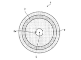
図3は、蛍光体ホイール1の正面図である。図4は、蛍光体ホイール1の横断面図である。蛍光体ホイール1は、基板2、図示しない蛍光体を含む蛍光体層3を有する。基板2は、円形の薄板形状を呈する。基板2は、透明部材で構成されており、光を透過する性質を有する。基板2には、例えば、ガラス、白板、石英、水晶、サファイア、YAG(Yttrium Aluminum Garnet)などが用いられる。
FIG. 3 is a front view of the
基板2の中心には、円形の開口2aが形成されている。開口2aには、蛍光体ホイール1を回転させるための駆動部15の駆動軸が挿入される。駆動部15は、例えばモーターである。これにより、基板2の中心を通る回転軸5を中心に、基板2は回転可能とされる。なお、駆動部15は、ケーシング16内に設けられた駆動部保持部21によって保持される。
A
蛍光体層3は、基板2の中心と同じ中心の環状形状で、基板2の表面に塗布される。蛍光体層3は、例えば、蛍光体をバインダー(樹脂材料)に混合させたものを、基板2の表面に塗布することで形成される。蛍光体層3に照射されたレーザー光の一部は、蛍光体に吸収される。レーザー光を吸収した蛍光体は励起され、蛍光を発生させる。本実施例では、青色のレーザー光を吸収することによって黄色の蛍光を発生する蛍光体を用いているため、蛍光体ホイール1は波長変換部材として機能する。
The
ここで、光源装置10から光を射出させる場合には、回転軸5を中心に蛍光体ホイール1を回転させながら、蛍光体層3の一部にレーザー光を集光させて照射させる。したがって、レーザー光が照射される領域は蛍光体層3上を常に移動することとなり、蛍光体層3が局所的に高温になってしまうのを防ぐことができる。
Here, when light is emitted from the
図示は省略するが、基板2と蛍光体層3との間には、基板2側から入射するレーザー光は透過させるが、蛍光体層3で散乱された光は反射させるダイクロイックミラーが設けられている。基板2と蛍光体層3との間にダイクロイックミラーを設けることで、蛍光体層3で散乱されたレーザー光のうち基板2側に向けて進行する光を反射させて、後述するピックアップレンズ14側に進行させることができるので、光の利用効率の向上を図ることができる。
Although not shown, a dichroic mirror is provided between the
ピックアップレンズ14は、蛍光体層3から射出された光を集光させる。蛍光体ホイール1に入射したレーザー光は、蛍光体層3を透過する際に散乱され、ランバード放射となって様々な方向に進行する。そこで、蛍光体ホイール1から射出されたレーザー光と蛍光とをピックアップレンズ14で集光して照明光などとして利用することで、光の利用効率の向上を図る。
The
ケーシング16は、光源11、コリメートレンズ12、集光レンズ13、蛍光体ホイール(波長変換部材)1、駆動部15を内部に収容するケース部材である。図2に示すように、ケーシング16は、上ケース17と下ケース18とに分割される。ケーシング16は、上ケース17と下ケース18とを組み合わせて構成される。
The
上ケース17と下ケース18とを組み合わせることで、ケーシング16の内部には、光源11を収容する光源収容部19と、蛍光体ホイール1を収容する蛍光体ホイール収容部20とが形成される。蛍光体ホイール収容部20は、外部空間と遮断された密閉空間となっている。また、光源収容部19と蛍光体ホイール収容部20とは、互いに独立した空間として形成される。
By combining the
光源収容部19には、光源11が収容される。蛍光体ホイール収容部20には、蛍光体ホイール1が収容されるとともに、駆動部15、駆動部保持部21、集光レンズ13、ピックアップレンズ14も収容される。
The
光源収容部19と蛍光体ホイール収容部20とを隔てる隔壁は、コリメートレンズ12を含めて構成される。すなわち、コリメートレンズ12を配置しない状態では、光源収容部19と蛍光体ホイール収容部20とは連通した状態となっているが、光源収容部19と蛍光体ホイール収容部20との間にコリメートレンズ12を配置することで、収容部19,20同士が互いに独立した空間となる。
A partition that separates the
ここで、光源11から射出されたレーザー光を蛍光体ホイール1に入射させるために、光源収容部19と蛍光体ホイール収容部20とを隔てる隔壁は、透光性の部材で構成される必要がある。本実施例1で隔壁として用いるコリメートレンズ12は、光を透過させるので、光源収容部19と蛍光体ホイール収容部20とを隔てる隔壁として利用することが可能となる。
Here, in order for the laser light emitted from the
光源収容部19と蛍光体ホイール収容部20とを隔てる隔壁が、コリメートレンズ12を含めて構成されるので、隔壁部分にレンズとしての機能も発揮させることができる。したがって、収容部19,20を隔てるためだけに隔壁を設ける場合に比べて、材料の削減や、軽量化を図ることができる。
Since the partition which separates the light
なお、光源収容部19と蛍光体ホイール収容部20とを隔てる隔壁を、集光レンズ13を含めて構成してもよい。この場合、コリメートレンズ12は、光源収容部19側に収容されることとなる。集光レンズ13も光を透過させるものであるので、光源収容部19と蛍光体ホイール収容部20とを隔てる隔壁として利用することが可能となる。
In addition, you may comprise the partition which separates the light
また、光源収容部19と蛍光体ホイール収容部20とを隔てる隔壁を、コリメートレンズ12や集光レンズ13といった集光光学系を用いずに、透光性の部材、例えばガラス板やプラスチック板で別途に構成してもよい。
Moreover, the partition which separates the light
ケーシング16のうち、光源装置10からの光の射出方向となる面、すなわちピックアップレンズ14から射出された光が照射される面(射出面16a)は、透光性の部材で構成される。射出面16aは、例えば、ガラス板やプラスチック板で構成される。
In the
なお、射出面16aにレンズとしての機能を発揮させても構わない。例えば、ピックアップレンズ14を含めて射出面16aを構成してもよい。射出面16aのうち光の透過する部分にピックアップレンズ14を埋め込むように設けることで、上述したガラス板やプラスチック板などが不要となるため、部品点数の削減や省スペース化を図ることができる。また、ケーシング16のうち、射出面16a以外の部分は、熱伝導性の高い材料、例えば金属材料で構成される。
The
以上説明したように、蛍光体ホイール1が、外部と遮断された蛍光体ホイール収容部20に収容されるので、蛍光体層3の表面に埃が直接付着するのを防ぐことができる。上述したように、蛍光体層3のごく一部の領域に向けてレーザー光が集光されるので、蛍光体層3に埃が直接付着すると光の進行を妨げやすく、光の利用効率が低下しやすくなる。一方、本実施例では、蛍光体層3の表面のうちレーザー光が照射される領域に埃が直接付着するのを防ぐことができるので、光の利用効率の低下を抑えることができる。
As described above, since the
また、蛍光体層3を透過する光のエネルギーの一部が熱に変換されるとともに、その照射領域がごく一部の領域であるため、蛍光体層3の光の照射領域は非常に高温になりやすい。したがって、高温になりやすい蛍光体層3の表面への埃の付着を防ぐことによる不具合の発生、例えば、付着した埃の焦げ付きによる光の利用効率の低下などを抑えることができる。
In addition, a part of the energy of the light transmitted through the
また、光源11と蛍光体ホイール1とが別々の空間に収容されるので、一方で発生した熱が他方に伝わりにくくなる。これにより、例えば、光源11で発生した熱により蛍光体ホイール1の冷却効率が低下して光の変換効率が低下したり、蛍光体ホイール1で発生した熱により光源11の冷却効率が低下して発光効率が低下したりすることを抑制することができる。
Moreover, since the
また、駆動部15が、外部と遮断された密閉空間である蛍光体ホイール収容部20の内部に収容されるので、駆動部15の駆動によって発生する騒音が外部に漏れにくくなる。これにより、光源装置10の駆動時の静粛性の向上を図ることができる。
Moreover, since the
また、ケーシング16の一部が熱伝導性の高い金属材料で構成されているので、ケーシング16からの放熱効率を向上させることができ、蛍光体ホイール1や光源11で発生した熱を、ケーシング16を介して効率よく外部に放熱させることができる。
Moreover, since a part of
なお、本実施例1では、ケーシング16の内部に光源収容部19を形成して光源11を収容するように構成しているが、これに限られず、光源収容部19を形成せずに光源11をケーシング16の外部に設けてもよい。また、蛍光体ホイール収容部20には、蛍光体ホイール1さえ収容されていれば、蛍光体層3の表面への埃の付着を防ぐことができるので、集光レンズ13、ピックアップレンズ14、駆動部15などは、蛍光体ホイール収容部20の外部に設けられても構わない。また、蛍光体ホイール収容部20内での熱の発生量が増大してしまうものの、蛍光体ホイール収容部20に光源11も収容するように構成しても構わない。
In the first embodiment, the light
[変形例1]
図5は、実施例1の変形例1に係る光源装置10の分解斜視図である。図5に示すように、本変形例1では、ケーシング16の外周面、特に金属で構成された部分にフィン16bが形成されている。フィン16bがケーシング16の外周面に形成されることで、ケーシング16の放熱面積が増大されるので、ケーシング16からの放熱効率をより一層向上させることができる。したがって、蛍光体ホイール1や光源11で発生した熱を、ケーシング16を介して効率よく外部に放熱させることができる。
[Modification 1]
FIG. 5 is an exploded perspective view of the
[変形例2]
図6は、実施例1の変形例2に係る光源装置が備える蛍光体ホイール1の外観斜視図である。本変形例2では、基板2のうち蛍光体層3が塗布される面の反対面側に、複数の羽根部(流動部)22が突出形成されている。蛍光体ホイール1が回転することで、複数の羽根部22はその全体で、空気を流動させるシロッコファンとして機能する。
[Modification 2]
FIG. 6 is an external perspective view of the
したがって、蛍光体ホイール1を回転させることで、蛍光体ホイール1の周囲の空気、すなわち蛍光体ホイール収容部20の内部の空気を流動させることができ、蛍光体ホイール1の放熱効率をより一層向上させることができる。
Therefore, by rotating the
なお、羽根部22は、シロッコファンとして機能するものでなくてもよく、単に基板から突出するように形成された突起でもよい。このような突起であっても、蛍光体ホイール1を回転させれば、周囲の空気を流動させることができるので、蛍光体ホイール1の冷却効率の向上に寄与することができる。
In addition, the blade |
図7は、本発明の実施例2に係るプロジェクターの概略構成を示す図である。本実施例2に係るプロジェクター60は、実施例1に係る光源装置10を備える。蛍光体ホイール1には、光源11から射出されたレーザー光が励起光として入射する。蛍光体ホイール1に入射したレーザー光は蛍光体層(図示を省略)を励起させ、蛍光体から蛍光が射出される。蛍光体層を透過した光と、励起された蛍光とにより、光源装置10からは、赤色(R)光、緑色(G)光、青色(B)光を含む照明光が射出される。例えば、光源として青色レーザー、蛍光体として赤色と緑色の帯域を発光する蛍光体を含んだ蛍光体層とを用いれば、少ない構成で光の3原色を再現できる。
FIG. 7 is a diagram illustrating a schematic configuration of the projector according to the second embodiment of the invention. The
均一化光学系64は、光源装置10から入射した光の強度分布を均一化させる光学系であって、例えばロッドインテグレーターを有する。ダイクロイックミラー65は、均一化光学系64からの光のうちB光を透過させ、R光及びG光を反射する。ダイクロイックミラー66は、R光を透過させ、G光を反射する。ダイクロイックミラー65、66は、光源装置10からの光を色ごとに分離する色分離光学系として機能する。
The homogenizing
ダイクロイックミラー66を透過したR光は、反射ミラー67、68で反射した後、R光用の空間光変調装置70Rへ入射する。空間光変調装置70Rは、R光を画像信号に応じて変調する。ダイクロイックミラー66で反射したG光は、G光用の空間光変調装置70Gへ入射する。空間光変調装置70Gは、G光を画像信号に応じて変調する。ダイクロイックミラー65を透過したB光は、反射ミラー69で反射した後、B光用の空間光変調装置70Bへ入射する。空間光変調装置70R、70G、70Bは、例えば、透過型の液晶表示装置である。
The R light transmitted through the
色合成光学系であるクロスダイクロイックプリズム71は、空間光変調装置70R、70G、70Bでそれぞれ変調された各色光を合成する。投写光学系72は、クロスダイクロイックプリズム71で合成された各色光をスクリーン73へ投写する。
A cross
プロジェクター60は、蛍光体層の表面への埃の付着を抑えて光の利用効率の低下を抑えた光源装置10を備えるので、信頼性を向上させて、高品質な画像を得ることが可能となる。なお、プロジェクター60は、実施例1で説明した変形例1や変形例2に係る光源装置10を備えるように構成してもよい。
Since the
また、プロジェクター60は、空間光変調装置として透過型液晶表示装置を用いる場合に限られない。空間光変調装置としては、反射型液晶表示装置(Liquid Crystal On Silicon;LCOS)、DMD(Digital Micromirror Device)、GLV(Grating Light Valve)等を用いてもよい。
The
以上のように、本発明に係る光源装置は、プロジェクターに用いる場合に適している。 As described above, the light source device according to the present invention is suitable for use in a projector.
1 蛍光体ホイール(波長変換部材)、2 基板、2a 開口、3 蛍光体層、5 回転軸、10 光源装置、11 光源、12 コリメートレンズ(集光光学系)、13 集光レンズ(集光光学系)、14 ピックアップレンズ、15 駆動部、16 ケーシング、16a 射出面、16b フィン、17 上ケース、18 下ケース、19 光源収容部、20 蛍光体ホイール収容部(密閉空間)、21 駆動部保持部、22 羽根部(流動部)、60 プロジェクター、64 均一化光学系、65 ダイクロイックミラー、66 ダイクロイックミラー、67 反射ミラー、69 反射ミラー、70R 空間光変調装置、70G 空間光変調装置、70B 空間光変調装置、71 クロスダイクロイックプリズム、72 投写光学系、73 スクリーン
DESCRIPTION OF
Claims (7)
光源と、
前記光源から射出された励起光を前記蛍光体層に集光するように照射させる集光光学系と、
前記波長変換部材と前記光源と前記集光光学系とを収容するケーシングと、を備え、
前記集光光学系に含まれるレンズと前記ケーシングとによって構成された密閉空間に、前記波長変換部材が設けられ、
前記レンズが、前記密閉空間と、前記光源を収容する空間とを区画していることを特徴とする光源装置。 A wavelength conversion member having a substrate that is rotatable around a predetermined rotation axis, and a phosphor layer that includes the phosphor and is provided on the substrate;
A light source;
A condensing optical system for irradiating the phosphor layer with the excitation light emitted from the light source;
A casing that houses the wavelength conversion member , the light source, and the condensing optical system ;
In the sealed space formed by the lens and the casing included in the condensing optical system, the wavelength conversion member is provided,
The light source device , wherein the lens partitions the sealed space and a space for housing the light source.
前記駆動部は、前記密閉空間に収容されることを特徴とする請求項1又は2に記載の光源装置。 A drive unit for rotating the substrate;
The drive unit includes a light source device according to claim 1 or 2, characterized in that it is pre accommodated between Kimitsu closed space.
前記光源装置から射出された光を画像信号に応じて変調する空間光変調装置と、を備えることを特徴とするプロジェクター。 The light source device according to any one of claims 1 to 6 ,
A projector comprising: a spatial light modulator that modulates light emitted from the light source device according to an image signal.
Priority Applications (1)
| Application Number | Priority Date | Filing Date | Title |
|---|---|---|---|
| JP2010153672A JP5527059B2 (en) | 2010-07-06 | 2010-07-06 | Light source device and projector |
Applications Claiming Priority (1)
| Application Number | Priority Date | Filing Date | Title |
|---|---|---|---|
| JP2010153672A JP5527059B2 (en) | 2010-07-06 | 2010-07-06 | Light source device and projector |
Related Child Applications (1)
| Application Number | Title | Priority Date | Filing Date |
|---|---|---|---|
| JP2014084366A Division JP5804130B2 (en) | 2014-04-16 | 2014-04-16 | Light source device and projector |
Publications (2)
| Publication Number | Publication Date |
|---|---|
| JP2012018762A JP2012018762A (en) | 2012-01-26 |
| JP5527059B2 true JP5527059B2 (en) | 2014-06-18 |
Family
ID=45603895
Family Applications (1)
| Application Number | Title | Priority Date | Filing Date |
|---|---|---|---|
| JP2010153672A Active JP5527059B2 (en) | 2010-07-06 | 2010-07-06 | Light source device and projector |
Country Status (1)
| Country | Link |
|---|---|
| JP (1) | JP5527059B2 (en) |
Cited By (1)
| Publication number | Priority date | Publication date | Assignee | Title |
|---|---|---|---|---|
| CN104238243A (en) * | 2013-06-07 | 2014-12-24 | 索尼公司 | Optical unit, light source apparatus, and image display apparatus |
Families Citing this family (24)
| Publication number | Priority date | Publication date | Assignee | Title |
|---|---|---|---|---|
| JP2013162020A (en) | 2012-02-07 | 2013-08-19 | Seiko Epson Corp | Wavelength conversion element, light source device, and projector |
| JP2013162021A (en) * | 2012-02-07 | 2013-08-19 | Seiko Epson Corp | Wavelength conversion element, light source device, and projector |
| JP6015138B2 (en) * | 2012-05-31 | 2016-10-26 | 株式会社リコー | Image projection device |
| CN105051601B (en) * | 2013-04-18 | 2017-05-31 | 松下知识产权经营株式会社 | Projection-type image display device |
| WO2014196126A1 (en) * | 2013-06-06 | 2014-12-11 | ソニー株式会社 | Light source apparatus and image display apparatus |
| JP2015094860A (en) | 2013-11-12 | 2015-05-18 | 株式会社リコー | Illumination light source device and image projection device |
| WO2015087406A1 (en) | 2013-12-11 | 2015-06-18 | Necディスプレイソリューションズ株式会社 | Cooling structure, lighting optical system, projection display apparatus, and cooling method |
| CN106030197A (en) * | 2014-02-12 | 2016-10-12 | 株式会社小糸制作所 | Optical unit and vehicle lamp |
| DE102014102350B4 (en) * | 2014-02-24 | 2016-03-03 | Schott Ag | Converter arrangement with cooling for light sources with high luminance |
| US10114276B2 (en) * | 2014-10-10 | 2018-10-30 | Sony Corporation | Phosphor wheel, light source apparatus, and projection-type display apparatus |
| JP6669077B2 (en) * | 2014-11-12 | 2020-03-18 | ソニー株式会社 | Light source device, image display device, and optical unit |
| JP2016133671A (en) * | 2015-01-20 | 2016-07-25 | ソニー株式会社 | Light source device and projector |
| WO2016147226A1 (en) * | 2015-03-19 | 2016-09-22 | パナソニックIpマネジメント株式会社 | Housing, phosphor wheel device, and projection device |
| WO2017064866A1 (en) | 2015-10-16 | 2017-04-20 | セイコーエプソン株式会社 | Wavelength conversion device, illumination device, and projector |
| CN105589286B (en) * | 2015-12-24 | 2017-11-07 | 苏州佳世达光电有限公司 | Projection arrangement |
| JP6868784B2 (en) * | 2016-04-04 | 2021-05-12 | ソニーグループ株式会社 | Light source device and image display device |
| US10394110B2 (en) | 2016-10-03 | 2019-08-27 | Panasonic Intellectual Property Management Co., Ltd. | Phosphor wheel module, light source device, and projection display apparatus |
| JP6207000B2 (en) * | 2017-02-03 | 2017-10-04 | Necディスプレイソリューションズ株式会社 | Cooling structure, illumination optical system, projection display device, and cooling method |
| JP6206999B2 (en) * | 2017-02-03 | 2017-10-04 | Necディスプレイソリューションズ株式会社 | Cooling structure, illumination optical system, projection display device, and cooling method |
| JP6551752B2 (en) | 2017-02-15 | 2019-07-31 | カシオ計算機株式会社 | Light source device and projection device |
| JP7032634B2 (en) * | 2017-09-29 | 2022-03-09 | 日亜化学工業株式会社 | Optical engine and projector |
| JP6468615B2 (en) * | 2017-12-11 | 2019-02-13 | Necディスプレイソリューションズ株式会社 | Cooling structure of illumination optical system and projection display device |
| CN111344632B (en) | 2018-02-02 | 2021-12-03 | 麦克赛尔株式会社 | Light source device, projector, and lighting device |
| JP2020030314A (en) | 2018-08-22 | 2020-02-27 | マクセル株式会社 | Light source device, projector, and lighting unit |
Family Cites Families (4)
| Publication number | Priority date | Publication date | Assignee | Title |
|---|---|---|---|---|
| JP2001100315A (en) * | 1999-09-28 | 2001-04-13 | Nec Viewtechnology Ltd | Video projection device |
| JP4590707B2 (en) * | 2000-09-13 | 2010-12-01 | パナソニック株式会社 | Color sequential color display device |
| JP2007305455A (en) * | 2006-05-12 | 2007-11-22 | Toshiba Lighting & Technology Corp | Led lighting device |
| JP4662185B2 (en) * | 2008-05-15 | 2011-03-30 | カシオ計算機株式会社 | Light source device and projector |
-
2010
- 2010-07-06 JP JP2010153672A patent/JP5527059B2/en active Active
Cited By (2)
| Publication number | Priority date | Publication date | Assignee | Title |
|---|---|---|---|---|
| CN104238243A (en) * | 2013-06-07 | 2014-12-24 | 索尼公司 | Optical unit, light source apparatus, and image display apparatus |
| CN104238243B (en) * | 2013-06-07 | 2018-05-22 | 索尼公司 | Optical unit, light supply apparatus and image display device |
Also Published As
| Publication number | Publication date |
|---|---|
| JP2012018762A (en) | 2012-01-26 |
Similar Documents
| Publication | Publication Date | Title |
|---|---|---|
| JP5527059B2 (en) | Light source device and projector | |
| JP5804130B2 (en) | Light source device and projector | |
| US10520800B2 (en) | Phosphor wheel, phosphor wheel device including the same, light conversion device, and projection display apparatus | |
| JP5767444B2 (en) | Light source device and image projection device | |
| JP6402893B2 (en) | Optical wheel device and projection device | |
| JP6979572B2 (en) | Phosphor wheel and phosphor wheel device equipped with it, light conversion device, projection type display device | |
| JP2012098438A (en) | Wavelength conversion element, light source device, and projector | |
| JP2012018209A (en) | Light source device and projector | |
| WO2017098706A1 (en) | Light conversion device and projection display device provided with same | |
| JP2012181431A (en) | Light source device and projector | |
| JP7113318B2 (en) | Light source device and projection type image display device | |
| JP7145434B2 (en) | Phosphor wheel, phosphor wheel device provided with same, light conversion device, projection display device | |
| JP6777075B2 (en) | Light converter, light source, and projection display | |
| JP6589534B2 (en) | Wavelength conversion device, illumination device, and projector | |
| WO2017098705A1 (en) | Fluorescent substance wheel device, light conversion device provided with same, and projection display device | |
| JP2016200656A (en) | projector | |
| JP2018200490A (en) | Light source apparatus and image display apparatus | |
| JP6881460B2 (en) | Projection type display device | |
| JP2017151213A (en) | Optical device, illumination device, and projector | |
| JP6931770B2 (en) | Fluorescent wheel device, light source device, and projection type image display device | |
| JP6890248B2 (en) | Cooling device and projection type image display device | |
| JP7228010B2 (en) | solid state light source | |
| JP6680340B2 (en) | Light source device and image projection device | |
| JP6453495B2 (en) | Light source device and image projection device | |
| JP6279516B2 (en) | Light source device and image projection device |
Legal Events
| Date | Code | Title | Description |
|---|---|---|---|
| A621 | Written request for application examination |
Free format text: JAPANESE INTERMEDIATE CODE: A621 Effective date: 20130318 |
|
| A977 | Report on retrieval |
Free format text: JAPANESE INTERMEDIATE CODE: A971007 Effective date: 20131129 |
|
| A131 | Notification of reasons for refusal |
Free format text: JAPANESE INTERMEDIATE CODE: A131 Effective date: 20131203 |
|
| RD03 | Notification of appointment of power of attorney |
Free format text: JAPANESE INTERMEDIATE CODE: A7423 Effective date: 20131212 |
|
| A521 | Written amendment |
Free format text: JAPANESE INTERMEDIATE CODE: A523 Effective date: 20140129 |
|
| TRDD | Decision of grant or rejection written | ||
| A01 | Written decision to grant a patent or to grant a registration (utility model) |
Free format text: JAPANESE INTERMEDIATE CODE: A01 Effective date: 20140318 |
|
| A61 | First payment of annual fees (during grant procedure) |
Free format text: JAPANESE INTERMEDIATE CODE: A61 Effective date: 20140331 |
|
| R150 | Certificate of patent (=grant) or registration of utility model |
Ref document number: 5527059 Country of ref document: JP Free format text: JAPANESE INTERMEDIATE CODE: R150 |
|
| S531 | Written request for registration of change of domicile |
Free format text: JAPANESE INTERMEDIATE CODE: R313531 |
|
| R350 | Written notification of registration of transfer |
Free format text: JAPANESE INTERMEDIATE CODE: R350 |