JP2016200656A - projector - Google Patents
projector Download PDFInfo
- Publication number
- JP2016200656A JP2016200656A JP2015079016A JP2015079016A JP2016200656A JP 2016200656 A JP2016200656 A JP 2016200656A JP 2015079016 A JP2015079016 A JP 2015079016A JP 2015079016 A JP2015079016 A JP 2015079016A JP 2016200656 A JP2016200656 A JP 2016200656A
- Authority
- JP
- Japan
- Prior art keywords
- cooling
- optical component
- casing
- projector
- sealed
- Prior art date
- Legal status (The legal status is an assumption and is not a legal conclusion. Google has not performed a legal analysis and makes no representation as to the accuracy of the status listed.)
- Withdrawn
Links
Images


Classifications
-
- H—ELECTRICITY
- H04—ELECTRIC COMMUNICATION TECHNIQUE
- H04N—PICTORIAL COMMUNICATION, e.g. TELEVISION
- H04N9/00—Details of colour television systems
- H04N9/12—Picture reproducers
- H04N9/31—Projection devices for colour picture display, e.g. using electronic spatial light modulators [ESLM]
- H04N9/3141—Constructional details thereof
- H04N9/3144—Cooling systems
-
- G—PHYSICS
- G03—PHOTOGRAPHY; CINEMATOGRAPHY; ANALOGOUS TECHNIQUES USING WAVES OTHER THAN OPTICAL WAVES; ELECTROGRAPHY; HOLOGRAPHY
- G03B—APPARATUS OR ARRANGEMENTS FOR TAKING PHOTOGRAPHS OR FOR PROJECTING OR VIEWING THEM; APPARATUS OR ARRANGEMENTS EMPLOYING ANALOGOUS TECHNIQUES USING WAVES OTHER THAN OPTICAL WAVES; ACCESSORIES THEREFOR
- G03B21/00—Projectors or projection-type viewers; Accessories therefor
- G03B21/14—Details
- G03B21/16—Cooling; Preventing overheating
Landscapes
- Engineering & Computer Science (AREA)
- Multimedia (AREA)
- Signal Processing (AREA)
- Projection Apparatus (AREA)
- Physics & Mathematics (AREA)
- General Physics & Mathematics (AREA)
- Liquid Crystal (AREA)
- Transforming Electric Information Into Light Information (AREA)
Abstract
Description
本発明は、プロジェクターに関する。 The present invention relates to a projector.
従来、光源装置と、当該光源装置から出射された光を変調して画像情報に応じた画像を形成する光変調装置と、形成された画像をスクリーン等の被投射面上に拡大投射する投射光学装置と、を備えたプロジェクターが知られている。このようなプロジェクターとして、光学装置(光変調装置としての液晶パネルを含む)及び偏光変換素子を、外装筐体内を循環する空気によって冷却する冷却装置を備える構成が提案されている(例えば、特許文献1参照)。
この特許文献1に記載のプロジェクターは、2台のシロッコファン及びダクトを備えている。この2台のシロッコファンのそれぞれから送風された冷却風は、ダクトにより分割され、複数の冷却対象(光学装置及び偏光変換素子)のそれぞれに供給される。
Conventionally, a light source device, a light modulation device that modulates light emitted from the light source device to form an image according to image information, and projection optics that enlarges and projects the formed image onto a projection surface such as a screen And a projector including the apparatus. As such a projector, a configuration is proposed that includes a cooling device that cools an optical device (including a liquid crystal panel as a light modulation device) and a polarization conversion element by air circulating in the exterior housing (for example, Patent Documents). 1).
The projector described in
ところで、特許文献1に記載のプロジェクターでは、複数の冷却対象(例えば、光学装置及び偏光変換素子等)が密閉空間に配置されていないため、塵埃の多いところで当該プロジェクターを使用すると、光学装置等に塵埃が付着し、投射画像に影が見えるなどして画像が劣化するおそれがある。これに対し、上記塵埃の光学装置等への付着を抑制するため、複数の冷却対象を密閉筐体内に保持し、冷却風を当該密閉筐体内に流通させることで冷却することが考えられる。
しかしながら、密閉筐体内に複数(例えば、2つ)の冷却対象が保持されている場合、当該密閉筐体内を循環する冷却風の熱を吸熱する吸熱器及び当該吸熱器からの熱を当該密閉筐体外に放出するためには、装置が大型化するという問題がある。また、複数の冷却対象のそれぞれを適切な温度で管理することが難しいという問題がある。
By the way, in the projector described in
However, when a plurality of (for example, two) objects to be cooled are held in the sealed casing, a heat absorber that absorbs the heat of the cooling air circulating in the sealed casing and the heat from the heat absorber are transferred to the sealed casing. In order to release it outside the body, there is a problem that the apparatus becomes large. Moreover, there is a problem that it is difficult to manage each of the plurality of cooling objects at an appropriate temperature.
本発明は、上記課題の少なくとも一部を解決することを目的としたものであり、小型化できるプロジェクターを提供することを目的とする。 SUMMARY An advantage of some aspects of the invention is to provide a projector that can be downsized.
本発明の一態様に係るプロジェクターは、第1冷却対象及び第2冷却対象と、第1密閉筐体を有し、前記第1密閉筐体内の第1冷却気体を循環させて、前記第1密閉筐体内に配置された前記第1冷却対象を冷却する第1循環冷却装置と、第2密閉筐体を有し、前記第2密閉筐体内の第2冷却気体を循環させて、前記第2密閉筐体内に配置された前記第2冷却対象を冷却する第2循環冷却装置と、を備え、前記第1冷却対象は、入射される光を変調して画像を形成する光変調装置を有する画像形成部であり、前記第2冷却対象は、前記光変調装置による前記画像の形成に寄与する光学部品に含まれる第1光学部品であることを特徴とする。 A projector according to an aspect of the present invention includes a first cooling object, a second cooling object, and a first hermetic casing, and circulates a first cooling gas in the first hermetically sealed casing so that the first hermetic casing is circulated. A first circulation cooling device configured to cool the first cooling object disposed in the housing; and a second sealed housing, wherein the second cooling gas in the second sealed housing is circulated to form the second sealed And a second circulating cooling device that cools the second cooling target disposed in a housing, and the first cooling target includes a light modulation device that modulates incident light to form an image. The second cooling target is a first optical component included in an optical component that contributes to the formation of the image by the light modulation device.
上記一態様によれば、第1冷却対象及び第2冷却対象がそれぞれ別個の第1循環冷却装置及び第2循環冷却装置により冷却されるので、第1冷却対象及び第2冷却対象のそれぞれを適切に冷却し、かつ、適切な温度で管理できる。
ここで、第1冷却対象及び第2冷却対象のそれぞれが離間した位置に配置されている場合、当該第1及び第2冷却対象を1つの循環冷却装置により冷却する場合、当該循環冷却装置が大型化する。これに対し、上記一態様によれば、上記1つの循環冷却装置により第1冷却対象(画像形成部)及び第2冷却対象を冷却する場合に比べて、第1循環冷却装置及び第2循環冷却装置を小型化できる。また、第1循環冷却装置及び第2循環冷却装置をそれぞれ設けることにより、プロジェクター内における第1及び第2循環冷却装置の配置の自由度が高まる。従って、プロジェクターを小型化できる。
According to the above aspect, since the first cooling object and the second cooling object are cooled by the separate first circulation cooling device and second circulation cooling device, respectively, the first cooling object and the second cooling object are appropriately set. It can be cooled to a proper temperature and managed at an appropriate temperature.
Here, when each of the first cooling object and the second cooling object is disposed at a separated position, when the first and second cooling objects are cooled by one circulating cooling device, the circulating cooling device is large. Turn into. On the other hand, according to the one aspect, the first circulation cooling device and the second circulation cooling are compared with the case where the first cooling object (image forming unit) and the second cooling object are cooled by the one circulation cooling device. The device can be miniaturized. Further, by providing the first circulation cooling device and the second circulation cooling device, respectively, the degree of freedom of arrangement of the first and second circulation cooling devices in the projector is increased. Therefore, the projector can be reduced in size.
上記一態様では、前記第1光学部品は、偏光変換素子であることが好ましい。
上記一態様によれば、偏光変換素子を第2循環冷却装置により個別に冷却できる。これにより、画像形成部及び偏光変換素子のそれぞれの温度をより適切に管理できる。
In the above aspect, the first optical component is preferably a polarization conversion element.
According to the one aspect, the polarization conversion elements can be individually cooled by the second circulation cooling device. Thereby, each temperature of an image formation part and a polarization conversion element can be managed more appropriately.
上記一態様では、前記第1光学部品は、入射された励起光によって励起され蛍光光を出射する波長変換素子であることが好ましい。
上記一態様によれば、波長変換素子を第2循環冷却装置により個別に冷却できる。これにより、画像形成部及び波長変換素子のそれぞれの温度をより適切な温度で管理できる。
In the above aspect, the first optical component is preferably a wavelength conversion element that is excited by incident excitation light and emits fluorescent light.
According to the above aspect, the wavelength conversion element can be individually cooled by the second circulation cooling device. Thereby, each temperature of an image formation part and a wavelength conversion element can be managed by more suitable temperature.
上記一態様では、前記第1密閉筐体及び前記第2密閉筐体は、隔壁により分断され、前記隔壁は、前記光学部品を保持する光学部品用筐体と、前記光学部品に含まれる第2光学部品と、により構成されていることが好ましい。
上記一態様によれば、隔壁が光学部品用筐体と第2光学部品とにより構成されるので、第1密閉筐体及び第2密閉筐体を他の部品のみで構成する場合に比べて、部品点数を削減でき、かつ、小型化できる。また、光学部品用筐体及び第2光学部品により第1密閉筐体及び第2密閉筐体が分断されるので、確実に第1冷却対象及び第2冷却対象を冷却し、かつ、適切な温度で管理できる。
In the one aspect, the first sealed housing and the second sealed housing are separated by a partition, and the partition is included in the optical component housing for holding the optical component and the second included in the optical component. And an optical component.
According to the above aspect, since the partition wall is configured by the optical component casing and the second optical component, compared to the case where the first sealed casing and the second sealed casing are configured only by other components, The number of parts can be reduced and the size can be reduced. Further, since the first sealed casing and the second sealed casing are divided by the optical component casing and the second optical component, the first cooling target and the second cooling target are reliably cooled, and an appropriate temperature is set. Can be managed.
上記一態様では、前記第2光学部品は、入射される光を反射する反射部材を含むことが好ましい。
なお、上記反射部材としては、全反射ミラーの他、ダイクロイックミラー等を例示できる。
上記一態様によれば、反射部材が隔壁の一部を構成するので、当該反射部材により確実に第1密閉筐体及び第2密閉筐体を構成できる。
In the one aspect, it is preferable that the second optical component includes a reflecting member that reflects incident light.
In addition, as said reflection member, a dichroic mirror etc. other than a total reflection mirror can be illustrated.
According to the above aspect, since the reflecting member constitutes a part of the partition wall, the first sealed casing and the second sealed casing can be reliably configured by the reflecting member.
上記一態様では、前記第2光学部品は、レンズを含むことが好ましい。
上記一態様によれば、レンズが隔壁の一部を構成するので、当該レンズにより確実に第1密閉筐体及び第2密閉筐体を構成できる。
In the one aspect, it is preferable that the second optical component includes a lens.
According to the above aspect, since the lens constitutes a part of the partition wall, the first sealed housing and the second sealed housing can be reliably configured by the lens.
上記一態様では、前記第1循環冷却装置は、前記第1冷却気体を前記第1密閉筐体内で循環させる第1循環ファンと、循環される前記第1冷却気体を冷却する第1冷却器と、を備え、前記第2循環冷却装置は、前記第2冷却気体を前記第2密閉筐体内で循環させる第2循環ファンと、循環される前記第2冷却気体を冷却する第2冷却器と、を備えることが好ましい。
なお、上記冷却器としては、熱交換器や吸熱器等を例示できる。
上記一態様では、第1密閉筐体及び第2密閉筐体内において循環する第1冷却気体及び第2冷却気体を第1冷却器及び第2冷却器により冷却できる。従って、第1冷却気体及び第2冷却気体により確実に第1冷却対象及び第2冷却対象を冷却できる。
In the one aspect, the first circulation cooling device includes a first circulation fan that circulates the first cooling gas in the first sealed casing, and a first cooler that cools the circulated first cooling gas. The second circulation cooling device comprises: a second circulation fan that circulates the second cooling gas in the second sealed casing; and a second cooler that cools the circulated second cooling gas; It is preferable to provide.
Examples of the cooler include a heat exchanger and a heat absorber.
In the said one aspect | mode, the 1st cooling gas and 2nd cooling gas which circulate in a 1st sealed housing | casing and a 2nd sealed housing | casing can be cooled with a 1st cooler and a 2nd cooler. Therefore, the first cooling object and the second cooling object can be reliably cooled by the first cooling gas and the second cooling gas.
[第1実施形態]
以下、本発明の第1実施形態について、図面に基づいて説明する。
[プロジェクターの外観構成]
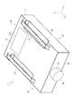
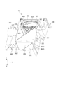
図1は、本実施形態に係るプロジェクター1を示す概要斜視図である。
本実施形態に係るプロジェクター1は、後述する照明装置31から出射される光を変調して画像情報に応じた画像を形成し、当該画像をスクリーン等の被投射面上に拡大投射する投射型表示装置である。
このプロジェクター1は、詳しくは後述するが、第1冷却対象及び第2冷却対象を備え、当該第1及び第2冷却対象のそれぞれが密閉筐体内に配置され、当該第1及び第2冷却対象に対して冷却空気(冷却気体)を循環させて冷却する機能を有する。
このプロジェクター1は、図1に示すように、外装を構成する外装筐体2を備える。
[First Embodiment]
Hereinafter, a first embodiment of the present invention will be described based on the drawings.
[External configuration of projector]
FIG. 1 is a schematic perspective view showing a
The
As will be described in detail later, the
As shown in FIG. 1, the
外装筐体2は、天面部21、底面部22、正面部23、背面部24及び左右の側面部25,26を有する略直方体形状に形成されている。
天面部21には、使用者がプロジェクター1を把持したり、天井等に設置された器具にプロジェクター1を固定したりする際に利用される一対の把手211が設けられている。また、天面部21には、後述する光源装置31A,31Bを外装筐体2内に交換可能に収納するための開口部(図示省略)が形成され、当該開口部は、カバー部材212によって覆われている。
底面部22には、図示を省略するが、設置台等の設置面上に載置される際に、当該設置面と接触する脚部が設けられている。
正面部23には、後述する画像形成装置3を構成する投射光学装置35の一部が露出する開口部231が形成されている。
これらの他、図示を省略するが、右側の側面部26には、外装筐体2外の空気を内部に導入する導入口が形成され、左側の側面部25には、外装筐体2内の空気を外部に排出する排気口が形成されている。
なお、以下の図及び説明において、Z方向は、投射光学装置35から投射された光の進行方向(投射方向)を示し、X方向及びY方向は、当該Z方向に直交し、かつ、互いに直交する方向を示す。これらのうち、Y方向は、平面視でZ方向が水平方向に沿うようにプロジェクター1が配置された場合に、鉛直方向とは反対方向である上方(すなわち、外装筐体2の底面部22から天面部21に向かう方向)を示し、X方向は、Z方向側(光の進行方向側)から見て左から右に向かう方向を示す。
The
The
Although not shown in the drawings, the
The
In addition to these, although not shown in the drawings, the right
In the following drawings and description, the Z direction indicates the traveling direction (projection direction) of the light projected from the projection
[プロジェクターの内部構成]
図2は、プロジェクター1の内部構成を示す模式図である。
プロジェクター1は、上記外装筐体2の他、図2に示すように、当該外装筐体2内に配置される画像形成装置3、冷却装置4を備える。この他、図示を省略するが、プロジェクター1は、当該プロジェクター1を制御する制御装置、及び、当該プロジェクター1を構成する電子部品に電力を供給する電源装置を備える。
[Internal configuration of projector]
FIG. 2 is a schematic diagram showing the internal configuration of the
In addition to the
[画像形成装置の構成]
画像形成装置3は、上記制御装置から入力される画像情報に応じた画像を形成及び投射する。この画像形成装置3は、照明装置31、均一化装置32、色分離装置33、電気光学装置34、投射光学装置35及び光学部品用筐体36を備える。
これらのうち、光学部品用筐体36は、内部に照明光軸Axが設定された箱状筐体であり、照明装置31、均一化装置32及び色分離装置33は、光学部品用筐体36内における照明光軸Ax上の位置に配置される。また、電気光学装置34及び投射光学装置35は、光学部品用筐体36外に位置するものの当該照明光軸Axに応じて配置される。なお、光学部品用筐体36の詳しい構成については、後述する。
[Configuration of Image Forming Apparatus]
The
Among these, the
照明装置31は、互いに対向配置される一対の光源装置31A,31Bと、当該一対の光源装置31A,31Bの間に配置される反射ミラー31Cと、を備える。
一対の光源装置31A,31Bは、それぞれ光源ランプ311及びリフレクター312と、これらを内部に収納する収納体313とを備える。そして、これら光源装置31A,31Bは、反射ミラー31Cに向けて光を出射する。
反射ミラー31Cは、光源装置31A,31Bから入射される光をそれぞれ同方向に反射させ、これにより、当該光を均一化装置32に入射させる。
The illuminating
Each of the pair of
The reflection mirror 31C reflects the light incident from the
均一化装置32は、照明装置31から出射された光束の中心軸に対する直交面内の照度を均一化する。この均一化装置32は、シネマフィルター321、第1レンズアレイ322、UVフィルター323、第2レンズアレイ324、偏光変換素子325及び重畳レンズ326を有する。
これらのうち、偏光変換素子325は、入射された光の偏光方向を一種類に揃えるものであり、本発明の偏光変換部に相当する。
色分離装置33は、均一化装置32から入射される光束を、赤(R)、緑(G)及び青(B)の3つの色光に分離する。この色分離装置33は、ダイクロイックミラー331,332、反射ミラー333〜336及びリレーレンズ337〜339を有する。
The
Among these, the
The
電気光学装置34は、分離された各色光を画像情報に応じて変調した後、変調された各色光を合成する。この電気光学装置34は、フィールドレンズ340、それぞれ色光毎に設けられる光変調装置としての液晶パネル341(赤、緑及び青用の液晶パネルを、それぞれ341R,341G,341Bとする)、入射側偏光板342及び出射側偏光板343と、1つの色合成装置344と、を有する。これらのうち、色合成装置344としては、ダイクロイックプリズムを採用できる。なお、電気光学装置34は、本発明の画像形成部に相当する。
投射光学装置35は、色合成装置344により合成された光束(画像を形成する光束)を上記被投射面上に拡大投射する投射レンズである。このような投射光学装置35としては、鏡筒内に複数のレンズが配置された組レンズを採用できる。
The electro-
The projection
[冷却装置の構成]
プロジェクター1は、上記構成の他、外装筐体2内に配置される冷却装置4を備える。この冷却装置4は、図2に示すように、第1冷却対象(例えば、電気光学装置34)が、密閉筐体内に配置され、当該第1冷却対象に冷却空気を循環させて冷却する第1循環冷却装置5と、第2冷却対象(例えば、偏光変換素子325)が、密閉筐体内に配置され、当該第2冷却対象に冷却空気を循環させて冷却する第2循環冷却装置6とを備える。このため、第1冷却対象及び第2冷却対象のそれぞれは、各循環冷却装置5,6により個別に冷却される。
[Configuration of cooling device]
In addition to the above configuration, the
[第1循環冷却装置の構成]
図3は、第1循環冷却装置5の概略構成を示すブロック図である。
第1循環冷却装置5は、第1密閉筐体511により形成される密閉空間S1内の冷却空気を循環させて流通させることにより、当該密閉空間S1内に配置された第1冷却対象を冷却し、第1冷却対象の冷却に供せられた第1冷却空気の熱を、循環流路を循環する第1液体に伝導して第1密閉筐体511外に流出させ、当該第1液体から他の循環流路を流通する第2液体に伝導して放熱するものである。なお、第1液体及び第2液体は、それぞれ異なる循環流路を流通する液体であることを示す呼称であり、それぞれ同じ成分の液体であってもよい。このような液体としては、水やプロピレングリコール等の不凍液を例示できる。
この第1循環冷却装置5は、図3に示すように、冷却装置51、吸熱装置52、放熱装置53及び冷却ファン54を備える。
[Configuration of the first circulating cooling device]
FIG. 3 is a block diagram showing a schematic configuration of the first
The first
As shown in FIG. 3, the first
[冷却装置の構成]
冷却装置51は、第1密閉筐体511内の第1冷却空気を循環させて、当該第1密閉筐体511内に配置された上記第1冷却対象を冷却する循環冷却装置である。この冷却装置51は、第1密閉筐体511の他、循環ファン512及び冷却ファン513を備える。
第1密閉筐体511は、冷却対象である電気光学装置34と、循環ファン512及び冷却ファン513と、後述する吸熱装置52を構成する吸熱器521と、が収納される筐体であり、これらが配置される密閉空間S1を形成する。この第1密閉筐体511は、当該第1密閉筐体511外の空気が内部に流入しにくい密閉構造として構成されている。
この第1密閉筐体511は、当該第1密閉筐体511の外縁を構成する外壁部511Aと、内側の面を構成する内壁部511Bと、を有し、これら外壁部511A及び内壁部511Bの一部は、光学部品用筐体36の一部である外側面部367(図7参照)により構成される。これら外壁部511A及び内壁部511Bが組み合わされることにより、第1密閉筐体511内には、環状の循環流路が形成されている。この循環流路上に、上記第1冷却対象(電気光学装置34)は、配置されている。
[Configuration of cooling device]
The
The first sealed casing 511 is a casing in which the electro-
The first hermetic casing 511 includes an
循環ファン512は、本発明の第1循環ファンに相当し、第1密閉筐体511内の冷却空気を吸引して吐出することにより、当該第1密閉筐体511内を循環させる。この循環ファン512は、本実施形態では軸流ファンにより構成され、後述する吸熱器521近傍に2つ設けられている。しかしながら、これに限らず、循環ファン512は、シロッコファンにより構成されていてもよく、循環ファン512の数も適宜変更可能であり、更には分散して配置してもよい。
冷却ファン513は、第1密閉筐体511内の冷却空気を吸引して、ダクト(図示省略)を介して上記第1冷却対象に送出する。この冷却ファン513は、上記電気光学装置34の各液晶パネル341に応じて設けられ、当該各液晶パネル341に冷却空気を送出する冷却ファン513R,513G,513Bを含む。このような冷却ファン513は、本実施形態ではシロッコファンにより構成されているが、軸流ファンにより構成されてもよく、冷却ファン513の数も適宜変更可能である。
The
The cooling
[吸熱装置の構成]
吸熱装置52は、上記第1密閉筐体511内の冷却空気から熱を吸熱し、当該熱が伝導された第1液体を、第1密閉筐体511外に位置する放熱装置53に流通させるものである。この吸熱装置52は、吸熱器521、タンク522及びポンプ523と、複数の流通管524と、を有する。なお、吸熱器521は、本発明の第1冷却器に相当する。
これらのうち、流通管524(5241〜5244)は、吸熱器521、タンク522及びポンプ523と、後述する放熱装置53とを、第1液体が内部を流通可能に接続する。
[Configuration of endothermic device]
The
Among these, the flow pipes 524 (5241 to 5244) connect the
吸熱器521は、本発明の第1冷却器に相当し、上記第1密閉筐体511内に配置され、タンク522及びポンプ523は、当該第1密閉筐体511外に配置されている。
これらのうち、吸熱器521は、流通管5241を介してタンク522と接続され、また、流通管5244を介して放熱装置53と接続されている。この吸熱器521は、第1密閉筐体511内を循環する冷却空気から熱を吸熱して当該冷却空気を冷却し、吸熱した熱を、内部を流通する第1液体に伝導させる。この吸熱器521により熱せられた第1液体は、流通管5241を介してタンク522に向けて流通する。
The
Among these, the
タンク522は、流通管5242を介してポンプ523と接続されている。このタンク522は、流通管5241〜5244を介して循環する第1液体を一時的に貯留する。これにより、空気や不純物が混入した第1液体が、ポンプ523に流入されることが抑制される。
ポンプ523は、流通管5242を介して流入された第1液体を、流通管5243を介して放熱装置53に圧送する。
The
The
[放熱装置及び冷却ファンの構成]
そして、放熱装置53に流通した第1液体は、当該放熱装置53に冷却ファン54から流通される冷却風によって冷却されて、流通管5244を介して吸熱器521に再度流通する。これにより、温度が低い第1液体が吸熱器521に流通し、当該吸熱器521にて第1密閉筐体511内の冷却空気から吸熱された熱を帯びた第1液体が、吸熱器521から流通管5241を介してタンク522に流入される。このように、吸熱装置52では、ポンプ523が駆動されることによって第1液体が循環される。
このように、第1循環冷却装置5では、吸熱器521により冷却空気が冷却されつつ、上記第1冷却対象である電気光学装置34が循環流路内で冷却される。
[Configuration of heat dissipation device and cooling fan]
Then, the first liquid that has flowed through the
As described above, in the first
[第2循環冷却装置の構成]
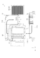
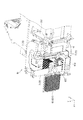
図4は、第2循環冷却装置6及び第2循環冷却装置6を循環する冷却空気の流路を示す断面図である。
第2循環冷却装置6は、第2密閉筐体7により形成される密閉空間S2内の冷却空気を循環させて流通させることにより、当該密閉空間S2に配置された第2冷却対象(例えば、偏光変換素子325)を冷却し、第2冷却対象の冷却に供せられた第2冷却空気の熱をヒートパイプ622(図5参照)へ循環する第3液体に伝導して第2密閉筐体7外に流出させ、当該ヒートパイプ622に接続されたヒートシンク631に冷却ファン(図示省略)から冷却風が送風されることにより、当該ヒートパイプ622内の第3液体が冷却され、上記熱が放熱されるものである。なお、第3液体は、それぞれ同じ成分の液体であってもよい。このような液体としては、水やプロピレングリコール等の不凍液を例示できる。
この第2循環冷却装置6は、図4に示すように、冷却装置61、吸熱装置62、放熱装置63及び冷却ファン(図示省略)を備える。
[Configuration of the second circulating cooling device]
FIG. 4 is a cross-sectional view showing the second circulating
The second circulating
As shown in FIG. 4, the second circulating
[冷却装置の構成]
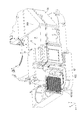
図5は、光学部品用筐体36及び第2循環冷却装置6をZ方向とは反対方向側から見た斜視図であり、図6は、光学部品用筐体36及び第2循環冷却装置6をY方向とは反対方向側から見た斜視図である。
冷却装置61は、第2密閉筐体7内の第2冷却空気を循環させて、当該第2密閉筐体7内に配置された上記第2冷却対象を冷却する循環冷却装置である。この冷却装置61は、図5及び図6において、第2密閉筐体7を構成する複数のダクト71〜73の他、循環ファン612を備える。
第2密閉筐体7は、冷却対象である偏光変換素子325と、循環ファン612と、後述する吸熱装置62を構成する吸熱器621と、が収納される筐体であり、これらが配置される密閉空間S2を形成する。この第2密閉筐体7は、当該密閉筐体7外の空気が内部に流入しにくい密閉構造として構成されている。
この第2密閉筐体7は、第1ダクト71、第2ダクト72、第3ダクト73及び光学部品用筐体36の一部により構成される。この光学部品用筐体36の一部は、詳しくは後述するが、光学部品用筐体36の外側面部361,362、ダイクロイックミラー331及びリレーレンズ337(図7参照)により構成される。このような構成により、第2密閉筐体7内には、環状の循環流路が形成されている。すなわち、上記第2冷却対象(偏光変換素子325)は、図4に示すように、この循環流路上に配置されている。
[Configuration of cooling device]
FIG. 5 is a perspective view of the
The
The second
The second
循環ファン612は、本発明の第2循環ファンに相当し、密閉筐体7内の冷却空気を吸引して吐出することにより、当該第2密閉筐体7内を循環させる。この循環ファン612は、本実施形態ではシロッコファンにより構成され、後述する吸熱器621近傍に設けられている。しかしながら、これに限らず、循環ファン612は、軸流ファンにより構成されていてもよく、循環ファン612の数も適宜変更可能であり、更には分散して配置してもよい。
The
[吸熱装置及び放熱装置の構成]
吸熱装置62は、上記第2密閉筐体7内の冷却空気から熱を吸熱し、当該熱が伝導された第3液体を、第2密閉筐体7外に位置する放熱装置63に流通させるものである。この吸熱装置62は、吸熱器621及びヒートパイプ622を有する。なお、吸熱器621は、本発明の第2冷却器に相当する。
これらのうち、ヒートパイプ622は、内部に第3液体が流通する流路を備える。このヒートパイプ622には、放熱装置63としてのヒートシンク631が接続され、当該ヒートシンク631に冷却風が供給されることにより、当該ヒートシンク631に接続されたヒートパイプ622が冷却される。これにより、吸熱器621により吸熱された熱が第2密閉筐体7内から放熱される。
このように、第2循環冷却装置6では、吸熱器621により冷却空気が冷却されつつ、上記第2冷却対象である偏光変換素子325が循環流路内で冷却される。
[Configuration of heat absorption device and heat dissipation device]
The
Among these, the
As described above, in the second circulating
[光学部品用筐体の構成]
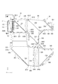
図7は、プロジェクター1の光学部品用筐体36をY方向側から見た平面図であり、図8は、光学部品用筐体36の一部を拡大して示す斜視図である。なお、図7及び図8の光学部品用筐体36は、天面部369を取り外した状態である。
光学部品用筐体36は、図7及び図8に示すように底面部360、外側面部361〜367、内側面部368及び天面部369(図5参照)を備える。
底面部360は、略U字状に形成される。この底面部360の外側の外縁のそれぞれからは、Y方向に延出する上記外側面部361〜367が設けられている。また、底面部360の中央部分には、Y方向に延出する略三角柱状の内側面部368が設けられている。これら底面部360、外側面部361〜367及び内側面部368は、一体成形されている。しかしながら、本発明は、これに限られず、それぞれが別部材として形成されていてもよい。
また、底面部360の偏光変換素子325が配置される位置に対応する部分には、開口部H1が形成されている。
[Configuration of optical component casing]
FIG. 7 is a plan view of the
As shown in FIGS. 7 and 8, the
The
In addition, an opening H1 is formed in a portion corresponding to the position where the
外側面部361は、光学部品用筐体36をY方向側から見て、最もX方向側に位置する側面部である。この外側面部361のZ方向とは反対方向側の端部が外側面部362と接続されており、Z方向側の端部が外側面部367と接続されている。この外側面部361には、溝部3611,3612,3613が形成されている。また、内側面部368の上記溝部3611,3612に対向する位置には、溝部3681,3682が形成されている。また、外側面部366の上記溝部3613に対向する位置には、溝部3661が形成されている。これら溝部3611,3681には、上記ダイクロイックミラー331がY方向側から嵌め込まれる。また、溝部3612,3682には、重畳レンズ326がY方向側から嵌め込まれる。更に、溝部3613,3661には、ダイクロイックミラー332がY方向側から嵌め込まれる。これにより、ダイクロイックミラー331,332及び重畳レンズ326が光学部品用筐体36に確実に固定される。
これらのうち、ダイクロイックミラー331は、光学部品用筐体36に固定されることで、当該光学部品用筐体36とともに、本発明の隔壁を形成する。すなわち、ダイクロイックミラー331は、第2循環冷却装置6の第2密閉筐体7の一部を構成する。なお、ダイクロイックミラー331は、本発明の第2光学部品及び反射部材に相当する。
The outer
Among these, the
外側面部362は、光学部品用筐体36をY方向側から見て、最もZ方向とは反対方向側に位置する側面部である。この外側面部362のX方向側の端部は、前述したように外側面部361と接続されており、X方向とは反対方向側の端部が外側面部363と接続されている。この外側面部362は、Z方向と反対方向に突出する突出部3620を有する。この突出部3620には、図7及び図8に示すように、上記シネマフィルター321、第1レンズアレイ322、UVフィルター323、第2レンズアレイ324及び偏光変換素子325が配置される。第1レンズアレイ322は、本発明の第2光学部品及びレンズに相当する。
また、外側面部362には、溝部3621が形成されている。また、内側面部368の上記溝部3621に対向する位置には、溝部3683が形成されている。これら溝部3621,3683には、上記リレーレンズ337がY方向側から嵌め込まれる。これにより、リレーレンズ337は、光学部品用筐体36に固定されることで、当該光学部品用筐体36とともに、本発明の隔壁を形成する。すなわち、リレーレンズ337は、第2循環冷却装置6の第2密閉筐体7の一部を構成する。なお、リレーレンズ337は、本発明の第2光学部品及びレンズに相当する。
The outer
Further, a
外側面部363は、光学部品用筐体36をY方向側から見て、最もX方向とは反対方向側で、かつ、最もZ方向とは反対側に位置する側面部である。この外側面部363のX方向側の端部は、前述したように外側面部362と接続され、X方向とは反対方向側の端部は、外側面部364と接続されている。この外側面部363の両端部には、溝部3631,3632が形成され、当該溝部3631,3632には、反射ミラー333がY方向側から嵌め込まれる。これにより、反射ミラー333が確実に光学部品用筐体36に固定される。
The outer
外側面部364は、光学部品用筐体36をY方向側から見て、最もX方向とは反対方向側に位置し、かつ、上記外側面部361と対向する位置に配置される側面部である。この外側面部364のZ方向とは反対方向側の端部は、前述したように外側面部363と接続され、Z方向側の端部は、外側面部365と接続されている。この外側面部364には、溝部3641,3642が形成されている。また、内側面部368の当該溝部3641,3642に対向する位置には、溝部3684,3685が形成されている。これら溝部3641,3684には、リレーレンズ338がY方向側から嵌め込まれ、溝部3642,3685には、リレーレンズ339がY方向側から嵌め込まれる。これにより、リレーレンズ338,339が確実に光学部品用筐体36に固定される。
The outer
外側面部365は、光学部品用筐体36をY方向側から見て、X方向とは反対方向側で、かつ、最もZ方向側に位置する側面部である。この外側面部365のZ方向とは反対方向側の端部は、前述したように外側面部364と接続され、Z方向側の端部は、外側面部366と接続されている。この外側面部365には、反射ミラー334が固定されている。
The outer
外側面部366は、光学部品用筐体36をY方向側から見て、最もZ方向側に位置するU字状の側面部である。この外側面部366のZ方向とは反対方向側の端部は、前述したように外側面部365と接続され、Z方向側の端部は、外側面部366と接続されている。この外側面部365には、反射ミラー334が固定されている。
また、外側面部366には、一対の溝部3661,3662,3663が形成され、それぞれフィールドレンズ340がY方向側から嵌め込まれ、固定されている。
The outer
In addition, a pair of
外側面部367は、光学部品用筐体36をY方向側から見て、最もXZ方向側に位置する側面部であり、上記外側面部363に対向する位置に配置されている。この外側面部367のZ方向とは反対方向側の端部は、前述したように外側面部361と接続され、Z方向側の端部は、外側面部366と接続されている。この外側面部367には、反射ミラー336が固定されている。
また、内側面部368のXZ方向側の面には、反射ミラー335が固定されている。
The outer
A
[光学部品用筐体内における密閉空間]
上述したように、底面部360には、開口部H1が形成され、当該開口部H1を囲むように、ダイクロイックミラー331及びリレーレンズ337が光学部品用筐体36に固定されている。これにより、開口部H1から流通した第2冷却空気は、突出部3620、第1レンズアレイ322及び光学部品用筐体36におけるダイクロイックミラー331及びリレーレンズ337により囲まれた空間、すなわち、密閉空間S2内を流通する。
なお、天面部369には、偏光変換素子325のY方向側に開口部H2(図9参照)が設けられている。また、当該開口部H1,H2の形状は、略同形状に形成される。
[Enclosed space in optical component casing]
As described above, the opening portion H1 is formed in the
The
[冷却装置の循環流路]
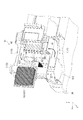
図9は、第2循環冷却装置6を光の出射方向の反対側から見た断面斜視図であり、図10は、第2循環冷却装置6を図9とは異なる角度から見た断面斜視図である。
冷却装置61の第2密閉筐体7は、図9及び図10に示すように、第1ダクト71、第2ダクト72及び第3ダクト73を備える。第1ダクト71の一方の端部は、底面部360の開口部H1に接続される。また、第1ダクト71の他方の端部は、循環ファン612に接続される。
第2ダクト72の一方の端部は、循環ファン612の吸引口に接続される。また、第2ダクト72の他方の端部は、第3ダクト73の端部に接続される。この第2ダクト72内には、上述したように、吸熱器621が配置され、当該吸熱器621により当該第2ダクト72を流通する第2冷却空気が冷却される。
第3ダクト73の一方の端部は、第2ダクト72に接続され、他方の端部は、天面部369に形成された開口部H2に接続される。また、上述したように、光学部品用筐体36内に配置されたダイクロイックミラー331及びリレーレンズ337が第2密閉筐体7の一部を構成している。
このような構成により、各ダクト71〜73、第1レンズアレイ322、ダイクロイックミラー331、リレーレンズ337及び光学部品用筐体36により密閉空間S2が形成される。そして、循環ファン612が駆動することにより、当該密閉空間S2内を図4に示すように、第2冷却空気が循環する。従って、第2冷却対象としての偏光変換素子325が冷却される。
[Cooling device circulation channel]
9 is a cross-sectional perspective view of the second circulating
As shown in FIGS. 9 and 10, the second sealed
One end of the
One end of the
With such a configuration, a sealed space S <b> 2 is formed by the
以上説明した本実施形態に係るプロジェクター1は、以下の効果を奏する。
第1冷却対象である電気光学装置34及び第2冷却対象である偏光変換素子325がそれぞれ別個の第1循環冷却装置5及び第2循環冷却装置6により冷却されるので、第1冷却対象及び第2冷却対象のそれぞれを適切に冷却し、かつ、適切な温度で管理できる。
ここで、第1冷却対象及び第2冷却対象のそれぞれが離間した位置に配置されている場合、当該第1及び第2冷却対象を1つの循環冷却装置により冷却する場合、当該循環冷却装置が大型化する。これに対し、本実施形態によれば、上記1つの循環冷却装置により第1冷却対象(電気光学装置34)及び第2冷却対象(偏光変換素子325)を冷却する場合に比べて、第1循環冷却装置5及び第2循環冷却装置6を小型化できる。また、第1循環冷却装置5及び第2循環冷却装置6をそれぞれ設けることにより、プロジェクター1内における第1循環冷却装置5及び第2循環冷却装置6の配置の自由度が高まる。従って、プロジェクター1を小型化できる。
The
Since the electro-
Here, when each of the first cooling object and the second cooling object is disposed at a separated position, when the first and second cooling objects are cooled by one circulating cooling device, the circulating cooling device is large. Turn into. On the other hand, according to the present embodiment, the first circulation is compared with the case where the first cooling object (electro-optical device 34) and the second cooling object (polarization conversion element 325) are cooled by the one circulation cooling device. The
偏光変換素子325を第2循環冷却装置6により個別に冷却できるので、電気光学装置34及び偏光変換素子325のそれぞれの温度をより適切に管理できる。
Since the
第2密閉筐体7を構成する隔壁が光学部品用筐体36とダイクロイックミラー331及びリレーレンズ337とにより構成されるので、第2密閉筐体7を他の部品のみで構成する場合に比べて、部品点数を削減でき、かつ、小型化できる。また、光学部品用筐体36、ダイクロイックミラー331及びリレーレンズ337により第1密閉筐体511及び第2密閉筐体7が分断されるので、確実に電気光学装置34及び偏光変換素子325を冷却し、かつ、適切な温度で管理できる。
Since the partition wall constituting the second
ダイクロイックミラー331が隔壁(第2密閉筐体7)の一部を構成するので、当該ダイクロイックミラー331により確実に第2密閉筐体7を構成できる。
また、リレーレンズ337が隔壁(第2密閉筐体7)の一部を構成するので、当該リレーレンズ337により確実に第1密閉筐体511及び第2密閉筐体7を構成できる。
Since the
Further, since the
第1密閉筐体511及び第2密閉筐体7内において循環する第1冷却空気及び第2冷却空気を吸熱器521及び吸熱器621により冷却できる。従って、第1冷却空気及び第2冷却空気により確実に電気光学装置34及び偏光変換素子325を冷却できる。
The first cooling air and the second cooling air circulating in the first sealed casing 511 and the second sealed
[第2実施形態]
次に、本発明の第2実施形態について説明する。
本実施形態のプロジェクターは、上記プロジェクター1と同様の構成を備えるが、第2循環冷却装置6の冷却装置61により冷却する冷却対象が異なる。すなわち、本実施形態では、偏光変換素子325に代えて、蛍光体ホイールが第2冷却対象である点が上記第1実施形態と相違する。なお、以下の説明では、既に説明した部分と同一又は略同一である部分については、同一の符号を付して説明を省略する。
[Second Embodiment]
Next, a second embodiment of the present invention will be described.
The projector according to the present embodiment has the same configuration as that of the
図11は、本実施形態の冷却装置61における第2冷却空気の循環流路及び冷却対象を示す模式図である。
本実施形態に係る第2循環冷却装置6Aを構成する冷却装置61は、第2密閉筐体7内を第2冷却空気を流通させることにより、蛍光体ホイール8を冷却する。このため、本実施形態では、光源装置31A及び光源装置31Bに代えて、固体レーザー光源(図示省略)を光源として用いる。
蛍光体ホイール8は、基板81、波長変換層82及びモーター83を備える。基板81は、Z方向側から見て円板状に形成され、かつ、透光性を有する部材により構成される。また、円板状の基板81のZ方向側の面には、ドーナツ状の波長変換層82が形成されている。この波長変換層82は、励起光が入射されることにより励起し、当該励起光を蛍光光(黄色光)出射する機能を有する。すなわち、波長変換層82は、上記励起光により励起される蛍光体を含んでいる。
また、基板81の略中央部分には、モーター83が接続され、当該モーター83が駆動することにより、当該基板81が回転するようになっている。
FIG. 11 is a schematic diagram showing the circulation path of the second cooling air and the cooling target in the
The
The
Further, a
この第2循環冷却装置6Aの冷却装置61において、循環ファン612が駆動すると、第2冷却空気が、図11に示すように、第2密閉筐体7内を循環する。また、モーター83の駆動により、回転中の基板81にY方向に向けて上記第2冷却空気が流通するので、効率よく蛍光体ホイール8を冷却できる。
In the
以上説明した本実施形態に係るプロジェクターによれば、上記第1実施形態に係るプロジェクター1の効果に加え、以下の効果を奏する。
蛍光体ホイール8(波長変換層82)を第2循環冷却装置6により個別に冷却できる。これにより、電気光学装置34及び蛍光体ホイール8のそれぞれの温度をより適切な温度で管理できる。
According to the projector according to the present embodiment described above, the following effects are obtained in addition to the effects of the
The phosphor wheel 8 (wavelength conversion layer 82) can be individually cooled by the second circulating
[実施形態の変形]
本発明は、上記各実施形態に限定されるものではなく、本発明の目的を達成できる範囲での変形、改良等は本発明に含まれるものである。
上記各実施形態では、第2循環冷却装置6により偏光変換素子325及び蛍光体ホイール8を冷却することとした。しかしながら、本発明は、これに限らない。例えば、冷却対象として、第1レンズアレイ322又は第2レンズアレイ324を冷却することとしてもよい。すなわち、第2循環冷却装置6により冷却される第2冷却対象は、光学部品であれば、どのような光学部品であってもよい。
[Modification of Embodiment]
The present invention is not limited to the above-described embodiments, and modifications, improvements, and the like within the scope that can achieve the object of the present invention are included in the present invention.
In each embodiment described above, the
上記各実施形態では、第1冷却対象及び第2冷却対象の冷却にそれぞれ第1冷却空気及び第2冷却空気を循環させるとした。しかしながら、本発明は、これに限らない。空気以外の気体を循環させて各冷却対象を冷却してもよい。 In the above embodiments, the first cooling air and the second cooling air are circulated for cooling the first cooling object and the second cooling object, respectively. However, the present invention is not limited to this. Each cooling object may be cooled by circulating a gas other than air.
上記各実施形態では、第1密閉筐体511が光学部品用筐体36の外側面部367により分断され、第2密閉筐体7が光学部品用筐体36、ダイクロイックミラー331及びリレーレンズ337により分断されることとした。しかしながら、本発明は、これに限らない。第1密閉筐体511の一部及び第2密閉筐体7の一部が光学部品用筐体36、若しくは光学部品用筐体36、ダイクロイックミラー331及びリレーレンズ337により構成されていなくてもよい。例えば、第2密閉筐体7は、リレーレンズ337を設けなくてもよい。この場合、リレーレンズ338が上記隔壁として機能する。
In each of the above embodiments, the first sealed casing 511 is divided by the
上記各実施形態では、第1循環冷却装置5の冷却装置51が吸熱器521を備え、第2循環冷却装置6の冷却装置61が吸熱器621を備えることとした。しかしながら、本発明は、これに限らない。例えば、これら吸熱器521,621を備えなくてもよい。この場合、例えば、第1密閉筐体511及び第2密閉筐体7のそれぞれを冷却する冷却部を別途設けてもよい。
In each of the above embodiments, the
上記第2実施形態では、蛍光体ホイール8の基板81は、モーター83の駆動により回転することとした。しかしながら、本発明は、これに限らない。例えば、基板81のZ方向とは反対方向側の面に、上記第2密閉筐体7内を流通する第2冷却空気が衝突するフィン等を設けるようにしてもよい。これによれば、モーター83を備えなくても、上記基板81が上記第2冷却空気により回転するので、蛍光体ホイール8を冷却できる。
In the second embodiment, the
上記各実施形態では、光変調装置として透過型の液晶パネル341(341R,341G,341B)を用いることとした。しかしながら、本発明は、これに限らない。例えば、透過型の液晶パネル341(341R,341G,341B)に代えて、反射型の液晶パネルを用いてもよい。この場合、色分離装置33を設けることなく、当該色合成装置344により、色分離及び色合成を実行するようにしてもよい。
In each of the above embodiments, the transmissive liquid crystal panel 341 (341R, 341G, 341B) is used as the light modulation device. However, the present invention is not limited to this. For example, instead of the transmissive liquid crystal panel 341 (341R, 341G, 341B), a reflective liquid crystal panel may be used. In this case, color separation and color synthesis may be executed by the
上記各実施形態では、プロジェクター1は、3つの液晶パネル341(341R,341G,341B)を備えるとしたが、本発明はこれに限らない。すなわち、2つ以下、あるいは、4つ以上の液晶パネルを用いたプロジェクターにも、本発明を適用可能である。
また、液晶パネルに代えて、デジタルマイクロミラーデバイス等を用いてもよい。
In each of the above embodiments, the
Further, a digital micromirror device or the like may be used instead of the liquid crystal panel.
上記第1実施形態では、プロジェクター1は、一対の光源装置31A,31Bを備えることとした。しかしながら、本発明は、これに限らない。例えば、光源装置は1つであってもよいし4つであってもよい。
上記各実施形態では、画像形成装置3は略U字状に構成されていたが、本発明はこれに限らない。例えば、略L字状に構成された画像形成装置を採用してもよい。
In the first embodiment, the
In each of the above embodiments, the
1…プロジェクター、322…第1レンズアレイ(第1光学部品)、325…偏光変換素子(第1光学部品)、331…ダイクロイックミラー(第2光学部品)、337…リレーレンズ(第2光学部品)、34…電気光学装置(画像形成部)、36…光学部品用筐体、5…第1循環冷却装置、511…第1密閉筐体、512…循環ファン(第1循環ファン)、521…吸熱器(第1冷却器)、6,6A…第2循環冷却装置、612…循環ファン(第2循環ファン)、621…吸熱器(第2冷却器)、7…第2密閉筐体、8…蛍光体ホイール(第1光学部品/波長変換素子)。
DESCRIPTION OF
Claims (7)
第1密閉筐体を有し、前記第1密閉筐体内の第1冷却気体を循環させて、前記第1密閉筐体内に配置された前記第1冷却対象を冷却する第1循環冷却装置と、
第2密閉筐体を有し、前記第2密閉筐体内の第2冷却気体を循環させて、前記第2密閉筐体内に配置された前記第2冷却対象を冷却する第2循環冷却装置と、を備え、
前記第1冷却対象は、入射される光を変調して画像を形成する光変調装置を有する画像形成部であり、
前記第2冷却対象は、前記光変調装置による前記画像の形成に寄与する光学部品に含まれる第1光学部品であることを特徴とするプロジェクター。 A first cooling object and a second cooling object;
A first circulating cooling device having a first sealed casing, circulating the first cooling gas in the first sealed casing, and cooling the first cooling object disposed in the first sealed casing;
A second circulating cooling device that has a second sealed casing, circulates a second cooling gas in the second sealed casing, and cools the second cooling object disposed in the second sealed casing; With
The first cooling target is an image forming unit having a light modulation device that modulates incident light to form an image,
The projector according to claim 1, wherein the second cooling target is a first optical component included in an optical component that contributes to the formation of the image by the light modulation device.
前記第1光学部品は、偏光変換素子であることを特徴とするプロジェクター。 The projector according to claim 1.
The projector according to claim 1, wherein the first optical component is a polarization conversion element.
前記第1光学部品は、入射された励起光によって励起され蛍光光を出射する波長変換素子であることを特徴とするプロジェクター。 The projector according to claim 1.
The projector according to claim 1, wherein the first optical component is a wavelength conversion element that is excited by incident excitation light and emits fluorescent light.
前記第1密閉筐体及び前記第2密閉筐体は、隔壁により分断され、
前記隔壁は、前記光学部品を保持する光学部品用筐体と、前記光学部品に含まれる第2光学部品と、により構成されていることを特徴とするプロジェクター。 In the projector as described in any one of Claims 1-3,
The first sealed housing and the second sealed housing are separated by a partition wall,
The said partition is comprised by the housing | casing for optical components holding the said optical component, and the 2nd optical component contained in the said optical component, The projector characterized by the above-mentioned.
前記第2光学部品は、入射される光を反射する反射部材を含むことを特徴とするプロジェクター。 The projector according to claim 4,
The projector according to claim 2, wherein the second optical component includes a reflecting member that reflects incident light.
前記第2光学部品は、レンズを含むことを特徴とするプロジェクター。 The projector according to claim 4 or 5,
The projector according to claim 2, wherein the second optical component includes a lens.
前記第1循環冷却装置は、
前記第1冷却気体を前記第1密閉筐体内で循環させる第1循環ファンと、
循環される前記第1冷却気体を冷却する第1冷却器と、を備え、
前記第2循環冷却装置は、
前記第2冷却気体を前記第2密閉筐体内で循環させる第2循環ファンと、
循環される前記第2冷却気体を冷却する第2冷却器と、を備えることを特徴とするプロジェクター。 The projector according to any one of claims 1 to 6,
The first circulating cooling device includes:
A first circulation fan for circulating the first cooling gas in the first sealed casing;
A first cooler for cooling the first cooling gas to be circulated,
The second circulating cooling device includes:
A second circulation fan for circulating the second cooling gas in the second sealed casing;
And a second cooler for cooling the second cooling gas to be circulated.
Priority Applications (3)
| Application Number | Priority Date | Filing Date | Title |
|---|---|---|---|
| JP2015079016A JP2016200656A (en) | 2015-04-08 | 2015-04-08 | projector |
| CN201610205935.2A CN106054507A (en) | 2015-04-08 | 2016-04-05 | Projector |
| US15/093,512 US9872001B2 (en) | 2015-04-08 | 2016-04-07 | Projector |
Applications Claiming Priority (1)
| Application Number | Priority Date | Filing Date | Title |
|---|---|---|---|
| JP2015079016A JP2016200656A (en) | 2015-04-08 | 2015-04-08 | projector |
Publications (2)
| Publication Number | Publication Date |
|---|---|
| JP2016200656A true JP2016200656A (en) | 2016-12-01 |
| JP2016200656A5 JP2016200656A5 (en) | 2018-05-17 |
Family
ID=57112083
Family Applications (1)
| Application Number | Title | Priority Date | Filing Date |
|---|---|---|---|
| JP2015079016A Withdrawn JP2016200656A (en) | 2015-04-08 | 2015-04-08 | projector |
Country Status (3)
| Country | Link |
|---|---|
| US (1) | US9872001B2 (en) |
| JP (1) | JP2016200656A (en) |
| CN (1) | CN106054507A (en) |
Cited By (3)
| Publication number | Priority date | Publication date | Assignee | Title |
|---|---|---|---|---|
| JPWO2018116689A1 (en) * | 2016-12-19 | 2019-10-24 | ソニー株式会社 | Light source device and projection display device |
| WO2019225013A1 (en) * | 2018-05-25 | 2019-11-28 | Necディスプレイソリューションズ株式会社 | Electronic device and projector |
| JP7405123B2 (en) | 2021-09-28 | 2023-12-26 | セイコーエプソン株式会社 | Light source devices, lighting devices and projectors |
Families Citing this family (5)
| Publication number | Priority date | Publication date | Assignee | Title |
|---|---|---|---|---|
| JP7003563B2 (en) * | 2017-10-18 | 2022-01-20 | セイコーエプソン株式会社 | projector |
| CN109547760A (en) * | 2018-12-25 | 2019-03-29 | 深圳市锐图技术有限公司 | Projector |
| CN112147748A (en) * | 2019-06-28 | 2020-12-29 | 深圳光峰科技股份有限公司 | Optical assembly, optical machine assembly and display device |
| CN112711163A (en) * | 2019-10-25 | 2021-04-27 | 台达电子工业股份有限公司 | Projection device |
| CN111221210B (en) * | 2020-01-16 | 2020-11-10 | 无锡视美乐激光显示科技有限公司 | Wavelength conversion mechanism, projection apparatus, and fluorescence excitation method |
Citations (2)
| Publication number | Priority date | Publication date | Assignee | Title |
|---|---|---|---|---|
| JP2009133991A (en) * | 2007-11-29 | 2009-06-18 | Seiko Epson Corp | Projector |
| JP2014092599A (en) * | 2012-11-01 | 2014-05-19 | Panasonic Corp | Optical conversion device and projection display device including optical conversion device |
Family Cites Families (15)
| Publication number | Priority date | Publication date | Assignee | Title |
|---|---|---|---|---|
| AU747281B2 (en) * | 1998-06-08 | 2002-05-09 | Karlheinz Strobl | Efficient light engine systems, components and methods of manufacture |
| TW514350U (en) * | 2001-06-22 | 2002-12-11 | Coretronic Corp | Projecting device with heat-dissipating fan |
| JP2003066404A (en) * | 2001-08-27 | 2003-03-05 | Sony Corp | Liquid crystal projector |
| US20040264192A1 (en) * | 2003-05-06 | 2004-12-30 | Seiko Epson Corporation | Light source apparatus, method of manufacture therefor, and projection-type display apparatus |
| JP4419646B2 (en) * | 2004-03-30 | 2010-02-24 | セイコーエプソン株式会社 | Optical apparatus and projector |
| KR100683171B1 (en) * | 2005-03-08 | 2007-02-15 | 삼성전자주식회사 | Cooling apparatus and projector having the same |
| JP4265632B2 (en) | 2006-08-31 | 2009-05-20 | セイコーエプソン株式会社 | projector |
| JP4703539B2 (en) * | 2006-10-31 | 2011-06-15 | 三洋電機株式会社 | projector |
| CN201017162Y (en) * | 2007-02-25 | 2008-02-06 | 李洪斌 | Dustproof heat radiating device of projector |
| CN101377613A (en) * | 2007-08-31 | 2009-03-04 | 佳世达科技股份有限公司 | Projection device and heat radiation method |
| JP5109558B2 (en) | 2007-09-28 | 2012-12-26 | セイコーエプソン株式会社 | projector |
| US20110037954A1 (en) * | 2008-03-17 | 2011-02-17 | Sanyo Electric Co., Ltd. | Projector |
| US8678597B2 (en) | 2009-03-30 | 2014-03-25 | Nec Display Solutions, Ltd. | Projection type display device |
| KR101102400B1 (en) * | 2009-06-09 | 2012-01-05 | 엘지전자 주식회사 | Control method of projector |
| JP5845803B2 (en) * | 2011-10-21 | 2016-01-20 | セイコーエプソン株式会社 | projector |
-
2015
- 2015-04-08 JP JP2015079016A patent/JP2016200656A/en not_active Withdrawn
-
2016
- 2016-04-05 CN CN201610205935.2A patent/CN106054507A/en active Pending
- 2016-04-07 US US15/093,512 patent/US9872001B2/en active Active
Patent Citations (2)
| Publication number | Priority date | Publication date | Assignee | Title |
|---|---|---|---|---|
| JP2009133991A (en) * | 2007-11-29 | 2009-06-18 | Seiko Epson Corp | Projector |
| JP2014092599A (en) * | 2012-11-01 | 2014-05-19 | Panasonic Corp | Optical conversion device and projection display device including optical conversion device |
Cited By (10)
| Publication number | Priority date | Publication date | Assignee | Title |
|---|---|---|---|---|
| JPWO2018116689A1 (en) * | 2016-12-19 | 2019-10-24 | ソニー株式会社 | Light source device and projection display device |
| JP7003935B2 (en) | 2016-12-19 | 2022-01-21 | ソニーグループ株式会社 | Light source device and projection type display device |
| WO2019225013A1 (en) * | 2018-05-25 | 2019-11-28 | Necディスプレイソリューションズ株式会社 | Electronic device and projector |
| CN112352195A (en) * | 2018-05-25 | 2021-02-09 | 夏普Nec显示器解决方案株式会社 | Electronic device and projector |
| JPWO2019225013A1 (en) * | 2018-05-25 | 2021-06-10 | シャープNecディスプレイソリューションズ株式会社 | Electronics and projectors |
| JPWO2019225679A1 (en) * | 2018-05-25 | 2021-06-10 | シャープNecディスプレイソリューションズ株式会社 | Electronics and projectors |
| JP7036915B2 (en) | 2018-05-25 | 2022-03-15 | シャープNecディスプレイソリューションズ株式会社 | Electronic devices and projectors |
| JP7036911B2 (en) | 2018-05-25 | 2022-03-15 | シャープNecディスプレイソリューションズ株式会社 | Electronic devices and projectors |
| US11330234B2 (en) | 2018-05-25 | 2022-05-10 | Sharp Nec Display Solutions, Ltd. | Electronic device and projectors |
| JP7405123B2 (en) | 2021-09-28 | 2023-12-26 | セイコーエプソン株式会社 | Light source devices, lighting devices and projectors |
Also Published As
| Publication number | Publication date |
|---|---|
| US20160301901A1 (en) | 2016-10-13 |
| US9872001B2 (en) | 2018-01-16 |
| CN106054507A (en) | 2016-10-26 |
Similar Documents
| Publication | Publication Date | Title |
|---|---|---|
| JP2016200656A (en) | projector | |
| JP5527059B2 (en) | Light source device and projector | |
| JP5804130B2 (en) | Light source device and projector | |
| US10890835B2 (en) | Light conversion device, light source apparatus, and projection display apparatus with improved cooling efficiency | |
| US10848722B2 (en) | Projector | |
| JP2016200316A (en) | Heat exchange device, cooling device and projector | |
| US10852628B2 (en) | Projector | |
| JP2006208488A (en) | Rear projector | |
| JPWO2019035282A1 (en) | Projection type display device | |
| JP2017120348A (en) | Light source device, illumination device, and projector | |
| JP6881460B2 (en) | Projection type display device | |
| JP2016218383A (en) | projector | |
| JP2016200657A (en) | projector | |
| JP6813118B2 (en) | Lighting equipment and projector | |
| JP6760308B2 (en) | projector | |
| JP2021060603A (en) | Illuminating device and projector | |
| JP6578714B2 (en) | projector | |
| JP2017072706A (en) | projector | |
| JP6683288B2 (en) | projector | |
| JP2018084727A (en) | Optical device and projector | |
| JP2017072705A (en) | projector | |
| JP2023049263A (en) | projector | |
| JP2016200655A (en) | projector | |
| JP2024003114A (en) | Light modulator and projector | |
| JP2024054504A (en) | projector |
Legal Events
| Date | Code | Title | Description |
|---|---|---|---|
| A521 | Request for written amendment filed |
Free format text: JAPANESE INTERMEDIATE CODE: A523 Effective date: 20180323 |
|
| A621 | Written request for application examination |
Free format text: JAPANESE INTERMEDIATE CODE: A621 Effective date: 20180323 |
|
| RD05 | Notification of revocation of power of attorney |
Free format text: JAPANESE INTERMEDIATE CODE: A7425 Effective date: 20180906 |
|
| RD03 | Notification of appointment of power of attorney |
Free format text: JAPANESE INTERMEDIATE CODE: A7423 Effective date: 20181115 |
|
| A977 | Report on retrieval |
Free format text: JAPANESE INTERMEDIATE CODE: A971007 Effective date: 20190124 |
|
| A131 | Notification of reasons for refusal |
Free format text: JAPANESE INTERMEDIATE CODE: A131 Effective date: 20190305 |
|
| A761 | Written withdrawal of application |
Free format text: JAPANESE INTERMEDIATE CODE: A761 Effective date: 20190507 |