JP5767444B2 - Light source device and image projection device - Google Patents
Light source device and image projection device Download PDFInfo
- Publication number
- JP5767444B2 JP5767444B2 JP2010137192A JP2010137192A JP5767444B2 JP 5767444 B2 JP5767444 B2 JP 5767444B2 JP 2010137192 A JP2010137192 A JP 2010137192A JP 2010137192 A JP2010137192 A JP 2010137192A JP 5767444 B2 JP5767444 B2 JP 5767444B2
- Authority
- JP
- Japan
- Prior art keywords
- light
- excitation light
- phosphor
- wavelength
- light source
- Prior art date
- Legal status (The legal status is an assumption and is not a legal conclusion. Google has not performed a legal analysis and makes no representation as to the accuracy of the status listed.)
- Active
Links
Images


Classifications
-
- G—PHYSICS
- G03—PHOTOGRAPHY; CINEMATOGRAPHY; ANALOGOUS TECHNIQUES USING WAVES OTHER THAN OPTICAL WAVES; ELECTROGRAPHY; HOLOGRAPHY
- G03B—APPARATUS OR ARRANGEMENTS FOR TAKING PHOTOGRAPHS OR FOR PROJECTING OR VIEWING THEM; APPARATUS OR ARRANGEMENTS EMPLOYING ANALOGOUS TECHNIQUES USING WAVES OTHER THAN OPTICAL WAVES; ACCESSORIES THEREFOR
- G03B21/00—Projectors or projection-type viewers; Accessories therefor
- G03B21/14—Details
- G03B21/20—Lamp housings
- G03B21/2006—Lamp housings characterised by the light source
- G03B21/2033—LED or laser light sources
- G03B21/204—LED or laser light sources using secondary light emission, e.g. luminescence or fluorescence
-
- F—MECHANICAL ENGINEERING; LIGHTING; HEATING; WEAPONS; BLASTING
- F21—LIGHTING
- F21K—NON-ELECTRIC LIGHT SOURCES USING LUMINESCENCE; LIGHT SOURCES USING ELECTROCHEMILUMINESCENCE; LIGHT SOURCES USING CHARGES OF COMBUSTIBLE MATERIAL; LIGHT SOURCES USING SEMICONDUCTOR DEVICES AS LIGHT-GENERATING ELEMENTS; LIGHT SOURCES NOT OTHERWISE PROVIDED FOR
- F21K9/00—Light sources using semiconductor devices as light-generating elements, e.g. using light-emitting diodes [LED] or lasers
- F21K9/60—Optical arrangements integrated in the light source, e.g. for improving the colour rendering index or the light extraction
- F21K9/64—Optical arrangements integrated in the light source, e.g. for improving the colour rendering index or the light extraction using wavelength conversion means distinct or spaced from the light-generating element, e.g. a remote phosphor layer
-
- F—MECHANICAL ENGINEERING; LIGHTING; HEATING; WEAPONS; BLASTING
- F21—LIGHTING
- F21K—NON-ELECTRIC LIGHT SOURCES USING LUMINESCENCE; LIGHT SOURCES USING ELECTROCHEMILUMINESCENCE; LIGHT SOURCES USING CHARGES OF COMBUSTIBLE MATERIAL; LIGHT SOURCES USING SEMICONDUCTOR DEVICES AS LIGHT-GENERATING ELEMENTS; LIGHT SOURCES NOT OTHERWISE PROVIDED FOR
- F21K9/00—Light sources using semiconductor devices as light-generating elements, e.g. using light-emitting diodes [LED] or lasers
- F21K9/60—Optical arrangements integrated in the light source, e.g. for improving the colour rendering index or the light extraction
- F21K9/68—Details of reflectors forming part of the light source
-
- F—MECHANICAL ENGINEERING; LIGHTING; HEATING; WEAPONS; BLASTING
- F21—LIGHTING
- F21V—FUNCTIONAL FEATURES OR DETAILS OF LIGHTING DEVICES OR SYSTEMS THEREOF; STRUCTURAL COMBINATIONS OF LIGHTING DEVICES WITH OTHER ARTICLES, NOT OTHERWISE PROVIDED FOR
- F21V13/00—Producing particular characteristics or distribution of the light emitted by means of a combination of elements specified in two or more of main groups F21V1/00 - F21V11/00
- F21V13/02—Combinations of only two kinds of elements
- F21V13/08—Combinations of only two kinds of elements the elements being filters or photoluminescent elements and reflectors
-
- F—MECHANICAL ENGINEERING; LIGHTING; HEATING; WEAPONS; BLASTING
- F21—LIGHTING
- F21V—FUNCTIONAL FEATURES OR DETAILS OF LIGHTING DEVICES OR SYSTEMS THEREOF; STRUCTURAL COMBINATIONS OF LIGHTING DEVICES WITH OTHER ARTICLES, NOT OTHERWISE PROVIDED FOR
- F21V14/00—Controlling the distribution of the light emitted by adjustment of elements
- F21V14/08—Controlling the distribution of the light emitted by adjustment of elements by movement of the screens or filters
-
- F—MECHANICAL ENGINEERING; LIGHTING; HEATING; WEAPONS; BLASTING
- F21—LIGHTING
- F21V—FUNCTIONAL FEATURES OR DETAILS OF LIGHTING DEVICES OR SYSTEMS THEREOF; STRUCTURAL COMBINATIONS OF LIGHTING DEVICES WITH OTHER ARTICLES, NOT OTHERWISE PROVIDED FOR
- F21V7/00—Reflectors for light sources
-
- G—PHYSICS
- G02—OPTICS
- G02B—OPTICAL ELEMENTS, SYSTEMS OR APPARATUS
- G02B26/00—Optical devices or arrangements for the control of light using movable or deformable optical elements
- G02B26/007—Optical devices or arrangements for the control of light using movable or deformable optical elements the movable or deformable optical element controlling the colour, i.e. a spectral characteristic, of the light
- G02B26/008—Optical devices or arrangements for the control of light using movable or deformable optical elements the movable or deformable optical element controlling the colour, i.e. a spectral characteristic, of the light in the form of devices for effecting sequential colour changes, e.g. colour wheels
-
- G—PHYSICS
- G02—OPTICS
- G02B—OPTICAL ELEMENTS, SYSTEMS OR APPARATUS
- G02B27/00—Optical systems or apparatus not provided for by any of the groups G02B1/00 - G02B26/00, G02B30/00
- G02B27/30—Collimators
-
- G—PHYSICS
- G03—PHOTOGRAPHY; CINEMATOGRAPHY; ANALOGOUS TECHNIQUES USING WAVES OTHER THAN OPTICAL WAVES; ELECTROGRAPHY; HOLOGRAPHY
- G03B—APPARATUS OR ARRANGEMENTS FOR TAKING PHOTOGRAPHS OR FOR PROJECTING OR VIEWING THEM; APPARATUS OR ARRANGEMENTS EMPLOYING ANALOGOUS TECHNIQUES USING WAVES OTHER THAN OPTICAL WAVES; ACCESSORIES THEREFOR
- G03B21/00—Projectors or projection-type viewers; Accessories therefor
- G03B21/005—Projectors using an electronic spatial light modulator but not peculiar thereto
- G03B21/006—Projectors using an electronic spatial light modulator but not peculiar thereto using LCD's
-
- G—PHYSICS
- G03—PHOTOGRAPHY; CINEMATOGRAPHY; ANALOGOUS TECHNIQUES USING WAVES OTHER THAN OPTICAL WAVES; ELECTROGRAPHY; HOLOGRAPHY
- G03B—APPARATUS OR ARRANGEMENTS FOR TAKING PHOTOGRAPHS OR FOR PROJECTING OR VIEWING THEM; APPARATUS OR ARRANGEMENTS EMPLOYING ANALOGOUS TECHNIQUES USING WAVES OTHER THAN OPTICAL WAVES; ACCESSORIES THEREFOR
- G03B21/00—Projectors or projection-type viewers; Accessories therefor
- G03B21/14—Details
- G03B21/142—Adjusting of projection optics
-
- G—PHYSICS
- G03—PHOTOGRAPHY; CINEMATOGRAPHY; ANALOGOUS TECHNIQUES USING WAVES OTHER THAN OPTICAL WAVES; ELECTROGRAPHY; HOLOGRAPHY
- G03B—APPARATUS OR ARRANGEMENTS FOR TAKING PHOTOGRAPHS OR FOR PROJECTING OR VIEWING THEM; APPARATUS OR ARRANGEMENTS EMPLOYING ANALOGOUS TECHNIQUES USING WAVES OTHER THAN OPTICAL WAVES; ACCESSORIES THEREFOR
- G03B21/00—Projectors or projection-type viewers; Accessories therefor
- G03B21/14—Details
- G03B21/20—Lamp housings
- G03B21/2066—Reflectors in illumination beam
-
- G—PHYSICS
- G03—PHOTOGRAPHY; CINEMATOGRAPHY; ANALOGOUS TECHNIQUES USING WAVES OTHER THAN OPTICAL WAVES; ELECTROGRAPHY; HOLOGRAPHY
- G03B—APPARATUS OR ARRANGEMENTS FOR TAKING PHOTOGRAPHS OR FOR PROJECTING OR VIEWING THEM; APPARATUS OR ARRANGEMENTS EMPLOYING ANALOGOUS TECHNIQUES USING WAVES OTHER THAN OPTICAL WAVES; ACCESSORIES THEREFOR
- G03B21/00—Projectors or projection-type viewers; Accessories therefor
- G03B21/14—Details
- G03B21/20—Lamp housings
- G03B21/208—Homogenising, shaping of the illumination light
-
- G—PHYSICS
- G03—PHOTOGRAPHY; CINEMATOGRAPHY; ANALOGOUS TECHNIQUES USING WAVES OTHER THAN OPTICAL WAVES; ELECTROGRAPHY; HOLOGRAPHY
- G03B—APPARATUS OR ARRANGEMENTS FOR TAKING PHOTOGRAPHS OR FOR PROJECTING OR VIEWING THEM; APPARATUS OR ARRANGEMENTS EMPLOYING ANALOGOUS TECHNIQUES USING WAVES OTHER THAN OPTICAL WAVES; ACCESSORIES THEREFOR
- G03B33/00—Colour photography, other than mere exposure or projection of a colour film
- G03B33/10—Simultaneous recording or projection
- G03B33/12—Simultaneous recording or projection using beam-splitting or beam-combining systems, e.g. dichroic mirrors
-
- H—ELECTRICITY
- H04—ELECTRIC COMMUNICATION TECHNIQUE
- H04N—PICTORIAL COMMUNICATION, e.g. TELEVISION
- H04N23/00—Cameras or camera modules comprising electronic image sensors; Control thereof
-
- H—ELECTRICITY
- H04—ELECTRIC COMMUNICATION TECHNIQUE
- H04N—PICTORIAL COMMUNICATION, e.g. TELEVISION
- H04N9/00—Details of colour television systems
- H04N9/12—Picture reproducers
- H04N9/31—Projection devices for colour picture display, e.g. using electronic spatial light modulators [ESLM]
- H04N9/3102—Projection devices for colour picture display, e.g. using electronic spatial light modulators [ESLM] using two-dimensional electronic spatial light modulators
- H04N9/3111—Projection devices for colour picture display, e.g. using electronic spatial light modulators [ESLM] using two-dimensional electronic spatial light modulators for displaying the colours sequentially, e.g. by using sequentially activated light sources
- H04N9/3117—Projection devices for colour picture display, e.g. using electronic spatial light modulators [ESLM] using two-dimensional electronic spatial light modulators for displaying the colours sequentially, e.g. by using sequentially activated light sources by using a sequential colour filter producing two or more colours simultaneously, e.g. by creating scrolling colour bands
-
- H—ELECTRICITY
- H04—ELECTRIC COMMUNICATION TECHNIQUE
- H04N—PICTORIAL COMMUNICATION, e.g. TELEVISION
- H04N9/00—Details of colour television systems
- H04N9/12—Picture reproducers
- H04N9/31—Projection devices for colour picture display, e.g. using electronic spatial light modulators [ESLM]
- H04N9/3141—Constructional details thereof
- H04N9/315—Modulator illumination systems
- H04N9/3155—Modulator illumination systems for controlling the light source
-
- H—ELECTRICITY
- H04—ELECTRIC COMMUNICATION TECHNIQUE
- H04N—PICTORIAL COMMUNICATION, e.g. TELEVISION
- H04N9/00—Details of colour television systems
- H04N9/12—Picture reproducers
- H04N9/31—Projection devices for colour picture display, e.g. using electronic spatial light modulators [ESLM]
- H04N9/3141—Constructional details thereof
- H04N9/315—Modulator illumination systems
- H04N9/3158—Modulator illumination systems for controlling the spectrum
-
- H—ELECTRICITY
- H04—ELECTRIC COMMUNICATION TECHNIQUE
- H04N—PICTORIAL COMMUNICATION, e.g. TELEVISION
- H04N9/00—Details of colour television systems
- H04N9/12—Picture reproducers
- H04N9/31—Projection devices for colour picture display, e.g. using electronic spatial light modulators [ESLM]
- H04N9/3141—Constructional details thereof
- H04N9/315—Modulator illumination systems
- H04N9/3161—Modulator illumination systems using laser light sources
-
- H—ELECTRICITY
- H04—ELECTRIC COMMUNICATION TECHNIQUE
- H04N—PICTORIAL COMMUNICATION, e.g. TELEVISION
- H04N9/00—Details of colour television systems
- H04N9/12—Picture reproducers
- H04N9/31—Projection devices for colour picture display, e.g. using electronic spatial light modulators [ESLM]
- H04N9/3141—Constructional details thereof
- H04N9/315—Modulator illumination systems
- H04N9/3164—Modulator illumination systems using multiple light sources
-
- F—MECHANICAL ENGINEERING; LIGHTING; HEATING; WEAPONS; BLASTING
- F21—LIGHTING
- F21Y—INDEXING SCHEME ASSOCIATED WITH SUBCLASSES F21K, F21L, F21S and F21V, RELATING TO THE FORM OR THE KIND OF THE LIGHT SOURCES OR OF THE COLOUR OF THE LIGHT EMITTED
- F21Y2115/00—Light-generating elements of semiconductor light sources
- F21Y2115/10—Light-emitting diodes [LED]
-
- F—MECHANICAL ENGINEERING; LIGHTING; HEATING; WEAPONS; BLASTING
- F21—LIGHTING
- F21Y—INDEXING SCHEME ASSOCIATED WITH SUBCLASSES F21K, F21L, F21S and F21V, RELATING TO THE FORM OR THE KIND OF THE LIGHT SOURCES OR OF THE COLOUR OF THE LIGHT EMITTED
- F21Y2115/00—Light-generating elements of semiconductor light sources
- F21Y2115/30—Semiconductor lasers
Landscapes
- Physics & Mathematics (AREA)
- Engineering & Computer Science (AREA)
- General Physics & Mathematics (AREA)
- Optics & Photonics (AREA)
- Multimedia (AREA)
- General Engineering & Computer Science (AREA)
- Signal Processing (AREA)
- Microelectronics & Electronic Packaging (AREA)
- Spectroscopy & Molecular Physics (AREA)
- Astronomy & Astrophysics (AREA)
- Projection Apparatus (AREA)
- Non-Portable Lighting Devices Or Systems Thereof (AREA)
Description
本発明は、光源装置及び画像投影装置に関し、より詳細には、例えばプロジェクタ等の投影型画像表示装置(画像投影装置)の光源として用いる光源装置及びそれを備える画像投影装置に関する。 The present invention relates to a light source device and an image projecting device, and more particularly to a light source device used as a light source of a projection type image display device (image projecting device) such as a projector and an image projecting device including the same.
近年、家庭内での映画鑑賞や会議でのプレゼンテーション等において、例えばプロジェクタ等の投影型画像表示装置を用いる機会が増えている。このようなプロジェクタでは、一般に、光源として、例えば高輝度の水銀ランプ等の放電型ランプが用いられる。また、最近の固体発光素子(例えば半導体レーザ、発光ダイオード等)の開発技術の進展に伴い、固体発光素子を利用したプロジェクタも提案されている(例えば特許文献1参照)。 In recent years, opportunities for using a projection type image display device such as a projector have increased in appreciation of movies at home and presentations at conferences. In such a projector, a discharge lamp such as a high-intensity mercury lamp is generally used as a light source. A projector using a solid-state light-emitting element has also been proposed with the progress of development technology of recent solid-state light-emitting elements (for example, semiconductor lasers, light-emitting diodes) (see, for example, Patent Document 1).
特許文献1で提案されているプロジェクタは、DLP(Digital Light Processing:登録商標)方式のプロジェクタである。この方式のプロジェクタでは、異なる色の光を1秒間に数千回程度、時分割で表示することにより画像をフルカラー表示する。
The projector proposed in
特許文献1のプロジェクタは、青色光(励起光)を射出する発光ダイオード(励起光源)と、励起光の出射側に設けられた透明基材と、透明基板を励起光の出射方向に直交する面内において回転させるモータとから成る光源装置を備える。
The projector disclosed in
この特許文献1の光源装置では、透明基材上に、励起光の照射により赤色光を発光する赤色蛍光体層、励起光の照射により緑色光を発光する緑色蛍光体層、及び、励起光を素通りさせる領域が互いに異なる領域に形成される。それゆえ、特許文献1のプロジェクタにおいて、所定の回転数で回転する透明基材に励起光を照射すると、青色光(励起光)、励起光により励起された赤色光及び緑色光が時分割で光源装置から射出される。
In the light source device of
上述のように、従来、水銀ランプを用いないプロジェクタが提案されており、このようなプロジェクタでは、水銀レスのプロジェクタを実現することができ、近年の環境問題に対応することが可能である。また、例えば半導体レーザ、発光ダイオード等の固体発光素子を光源として用いた場合、水銀ランプに比べて長寿命であり、輝度低下も小さいという利点も得られる。 As described above, a projector that does not use a mercury lamp has been conventionally proposed. With such a projector, a mercury-free projector can be realized, and it is possible to cope with recent environmental problems. Further, when a solid-state light emitting element such as a semiconductor laser or a light emitting diode is used as a light source, there are advantages that it has a longer life than a mercury lamp and a decrease in luminance is small.
しかしながら、上記特許文献1で提案されている技術は、DLP(登録商標)方式のプロジェクタ等のように、互いに波長の異なる複数の単色光を時分割で射出する光源装置(照明装置)にのみ適用可能である。例えば、3LCD(Liquid Crystal Display)方式のプロジェクタ等の画像表示装置のように、白色光を射出する光源装置を必要とする用途には適用することができない。
However, the technique proposed in
本発明は、上記現状を鑑みなされたものであり、本発明の目的は、例えば3LCD方式のプロジェクタ等の様々な用途に対しても適用可能な水銀レスの光源装置及びそれを備える画像投影装置を提供することである。 The present invention has been made in view of the above situation, and an object of the present invention is to provide a mercury-less light source device that can be applied to various uses such as a 3LCD projector, and an image projection device including the mercury-free light source device. Is to provide.
上記課題を解決するために、本発明の光源装置は、励起光源と、蛍光体と、反射膜と、反射防止膜と、第1光学系と、駆動部と、を備える構成とし、各部の機能を次のようにする。励起光源は、第1の波長を有する励起光を射出する。蛍光体は、励起光が照射された際に、第1の波長より長い第2の波長を有する光を発光するとともに、励起光の一部を透過させて、該透過した第1の波長の励起光と該発光した第2の波長の光とを合波して射出する。この蛍光体は駆動部が回転させる基板の照射位置において単一であり、回転する基板の回転円周方向に沿って連続して形成され、基板の中心を回転軸として回転可能である。反射膜は、蛍光体の励起光の入射側に設けられ、所定角度以下の入射角の励起光を透過するとともに蛍光体で発光した光を反射する。反射防止膜は、蛍光体の励起光の入射側に設けられ、励起光の反射を防止する。第1光学系は、反射膜及び励起光源間の光路上に設けられ、励起光を集光する。そして、駆動部は、基板の中心に駆動軸が接続され、蛍光体に照射される励起光の照射位置を時間とともに基板の回転円周方向へ移動させるよう基板を回転させる。そして、光源装置は、第1光学系で集光され反射防止膜を通過した励起光の反射膜への入射角が、所定角度以下となるよう構成される。なお、ここでいう「波長」は、単一波長だけでなく所定の波長帯域も含む意味である。 In order to solve the above problems, a light source device of the present invention is configured to include an excitation light source, a phosphor, a reflection film, an antireflection film, a first optical system, and a drive unit, and the function of each unit As follows. The excitation light source emits excitation light having a first wavelength. When the phosphor is irradiated with excitation light, the phosphor emits light having a second wavelength longer than the first wavelength, and transmits a part of the excitation light, thereby exciting the transmitted first wavelength. The light and the emitted light of the second wavelength are combined and emitted. This phosphor is single at the irradiation position of the substrate rotated by the drive unit, is formed continuously along the rotation circumferential direction of the rotating substrate, and can be rotated about the center of the substrate as a rotation axis. The reflection film is provided on the excitation light incident side of the phosphor, transmits the excitation light having an incident angle equal to or smaller than a predetermined angle, and reflects the light emitted from the phosphor. The antireflection film is provided on the incident side of the excitation light of the phosphor and prevents reflection of the excitation light. The first optical system is provided on the optical path between the reflective film and the excitation light source and collects the excitation light. The drive unit has a drive shaft connected to the center of the substrate, and rotates the substrate so that the irradiation position of the excitation light applied to the phosphor moves with time in the rotation circumferential direction of the substrate. The light source device is configured such that the incident angle of the excitation light, which is collected by the first optical system and passes through the antireflection film, to the reflection film is equal to or less than a predetermined angle. The “wavelength” here means not only a single wavelength but also a predetermined wavelength band.
また、本発明の画像投影装置は、光源装置部と、画像投影部とを備える構成とし、各部の機能を次のようにする。光源装置部は、上記本発明の光源装置と同様の構成にする。そして、画像投影部は、光源装置部から射出された光を用いて所定の画像光を生成し、該生成した画像光を外部に投影する。 Moreover, the image projector of this invention is set as the structure provided with a light source device part and an image projector, and the function of each part is as follows. The light source device section has the same configuration as the light source device of the present invention. The image projection unit generates predetermined image light using the light emitted from the light source device unit, and projects the generated image light to the outside.
本発明では、円周方向に沿って連続して形成され、回転可能である単一の蛍光体は、励起光の照射により、励起光の波長(第1の波長)より長い波長(第2の波長)を有する光を発光するとともに、励起光の一部を透過させて、該透過した励起光と、蛍光体で発光した光(以下、発光光という)とを合波して射出する。すなわち、本発明では、蛍光体から、励起光及び発光光とは異なる波長帯域の光が射出される。それゆえ、本発明では、例えば、励起光を青色光とし、発光光を赤色光及び緑色光の両成分を含む光(例えば黄色光等)とした場合には、白色光を蛍光体から射出することができる。 In the present invention, a single phosphor that is continuously formed and rotatable along the circumferential direction has a wavelength (second wavelength) longer than the wavelength of the excitation light (first wavelength) when irradiated with the excitation light. In addition to emitting light having a wavelength, a part of the excitation light is transmitted, and the transmitted excitation light and light emitted from the phosphor (hereinafter referred to as emission light) are combined and emitted. That is, in the present invention, light having a wavelength band different from the excitation light and the emitted light is emitted from the phosphor. Therefore, in the present invention, for example, when the excitation light is blue light and the emitted light is light including both components of red light and green light (for example, yellow light), white light is emitted from the phosphor. be able to.
上述のように、本発明では、励起光の第1の波長と発光光の第2の波長との組み合わせを適宜設定することにより、例えば白色光等を蛍光体から射出することができる。それゆえ、本発明によれば、例えば3LCD方式のプロジェクタ等の様々な用途に対しても適用可能な水銀レスの光源装置及びそれを備える画像投影装置を提供することができる。 As described above, in the present invention, for example, white light or the like can be emitted from the phosphor by appropriately setting the combination of the first wavelength of the excitation light and the second wavelength of the emitted light. Therefore, according to the present invention, it is possible to provide a mercury-free light source device that can be applied to various uses such as a 3LCD projector, and an image projection device including the mercury-free light source device.
以下に、本発明の実施形態に係る照明装置(光源装置)及びそれを備える画像表示装置の一例を、図面を参照しながら下記の順で説明する。なお、本実施形態では、画像表示装置として、3LCD方式のプロジェクタ(画像投影装置)を例に挙げ説明するが、本発明はこれに限定されない。
1.画像表示装置の構成例
2.光源装置部(照明装置)の構成例
3.蛍光部材の構成例
4.光源装置部の動作例
Hereinafter, an example of an illumination device (light source device) according to an embodiment of the present invention and an image display device including the illumination device will be described in the following order with reference to the drawings. In the present embodiment, a 3LCD projector (image projection apparatus) will be described as an example of the image display apparatus, but the present invention is not limited to this.
1. 1. Configuration example of
[1.画像表示装置の構成例]
図1に、本発明の一実施形態に係る画像表示装置の概略構成を示す。なお、図1では、説明を簡略化するため、主に、本実施形態の画像表示装置10において画像光を外部に投影する際に動作する要部のみを示す。また、図1には、透過型のLCD光変調素子を用いた3LCD方式のプロジェクタの構成例を示すが、本発明はこれに限定されない。本発明は、反射型のLCD光変調素子を用いる3LCD方式のプロジェクタにも適用可能である。
[1. Configuration example of image display apparatus]
FIG. 1 shows a schematic configuration of an image display apparatus according to an embodiment of the present invention. In FIG. 1, for the sake of simplification of description, only main parts that operate when image light is projected to the outside in the image display apparatus 10 of the present embodiment are mainly shown. FIG. 1 shows a configuration example of a 3LCD type projector using a transmissive LCD light modulation element, but the present invention is not limited to this. The present invention can also be applied to a 3LCD projector using a reflective LCD light modulation element.
画像表示装置10は、光源装置部1(照明装置)と、光学エンジン部2(画像投影部)とを備える。なお、光源装置部1の構成の説明は後で詳述する。
The image display device 10 includes a light source device unit 1 (illumination device) and an optical engine unit 2 (image projection unit). The configuration of the light
光学エンジン部2は、光源装置部1から射出された光(この例では白色光LW)を光学的に処理して画像光LIを生成し、その画像光LIを外部の例えばスクリーン等に拡大投影する。光学エンジン部2は、例えば、分光光学系20と、3つのLCD光変調素子(以下では、それぞれ第1LCDパネル21〜第3LCDパネル23という)と、プリズム24と、投影光学系25とを有する。なお、光学エンジン部2の構成は、図1に示す例に限定されず、例えば用途等に応じて適宜変更できる。例えば、各部間の光路上に必要となる各種光学素子を適宜配置してもよい。
The
また、この例の光学エンジン部2では、第1LCDパネル21の光出射面と、第3LCDパネル23の光出射面とが対向するように両者を配置し、その両者の対向方向に直交する方向に第2LCDパネル22を配置する。そして、第1LCDパネル21〜第3LCDパネル23の光出射面で囲まれた領域にプリズム24を配置する。また、この例では、プリズム24を挟んで、第2LCDパネル22の光出射面と対向する位置に投影光学系25を配置する。なお、分光光学系20は、第1LCDパネル21〜第3LCDパネル23の光入射側に設けられる。
Moreover, in the
分光光学系20は、例えばダイクロイックミラー、反射ミラー等で構成され、光源装置部1から入射される白色光LWを、青色光LB、緑色光LG及び赤色光LRに分光し、各波長成分の光を対応するLCDパネルに射出する。この例では、分光光学系20は、分光した青色光LB、緑色光LG及び赤色光LRをそれぞれ、第1LCDパネル21、第2LCDパネル22及び第3LCDパネル23に射出する。
The spectroscopic
第1LCDパネル21〜第3LCDパネル23のそれぞれは、透過型のLCDパネルで構成される。各LCDパネルは、図示しないパネルドライブ部からの駆動信号に基づいて、液晶セル(不図示)に封入された液晶分子の配列を変化させることにより、入射光を液晶セル単位で透過または遮断する(変調する)。そして、各LCDパネルは、変調した所定波長の光(変調光)をプリズム24に射出する。
Each of the
プリズム24は、第1LCDパネル21〜第3LCDパネル23からそれぞれ入射された各波長成分の変調光を合波し、その合波光、すなわち、画像光LIを投影光学系25に射出する。
The prism 24 combines the modulated light of each wavelength component incident from the
投影光学系25は、プリズム24から入射された画像光を、例えば外部のスクリーン等の表示面に拡大投影する。 The projection optical system 25 enlarges and projects the image light incident from the prism 24 onto a display surface such as an external screen.
[2.光源装置部1の構成例]
次に、本実施形態の光源装置部1の内部構成を、図1を参照しながら説明する。
[2. Configuration example of light source device unit 1]
Next, the internal configuration of the light
光源装置部1は、励起光源11と、第1集光光学系12(第1光学系)と、蛍光部材13と、モータ14(駆動部)と、第2集光光学系15(第2光学系)とを備える。そして、本実施形態の光源装置部1では、励起光源11の励起光Lの出射口側から、第1集光光学系12、蛍光部材13及び第2集光光学系15が、この順で配置される。この際、第1集光光学系12、蛍光部材13内の後述する層状の蛍光体32(以下、蛍光体層32という)、及び、第2集光光学系15が、励起光Lの光路上に位置するように配置する。
The
励起光源11は、所定波長(第1の波長)の光を射出する固体発光素子で構成する。この例では、励起光源11として、波長445nmの青色光を射出する青色レーザを用いる。なお、本実施形態では、蛍光体層32に入射する励起光Lの波長を、蛍光部材13内の後述する蛍光体層32における発光光の波長より短くする。
The excitation light source 11 is composed of a solid light emitting element that emits light of a predetermined wavelength (first wavelength). In this example, a blue laser that emits blue light having a wavelength of 445 nm is used as the excitation light source 11. In the present embodiment, the wavelength of the excitation light L incident on the
また、励起光源11として青色レーザを用いる場合、一つの青色レーザで所定出力の励起光Lを得る構成にしてもよいが、複数の青色レーザから射出される光を合波して所定出力の励起光Lを得る構成にしてもよい。さらに、青色光(励起光L)の波長は445nmに限定されず、青色光と呼ばれる光の波長帯域内の波長であれば任意の波長を用いることができる。 Further, when a blue laser is used as the excitation light source 11, a configuration in which the excitation light L having a predetermined output is obtained with one blue laser may be used. However, the light emitted from a plurality of blue lasers may be combined to be excited with a predetermined output. The light L may be obtained. Furthermore, the wavelength of blue light (excitation light L) is not limited to 445 nm, and any wavelength can be used as long as it is within the wavelength band of light called blue light.
第1集光光学系12は、励起光源11から射出された励起光Lを集光し、該集光された励起光L(以下、集光光という)を蛍光部材13に射出する。この際、集光光が、所定の入射角θで蛍光部材13に入射されるように、第1集光光学系12の例えばレンズ構成、焦点距離及び配置位置等のパラメータを設計する。また、集光光の入射角θは、例えば、蛍光部材13内の後述する反射膜31の透過特性(透過率の入射角依存性)に応じて適宜設定される。
The first condensing optical system 12 condenses the excitation light L emitted from the excitation light source 11 and emits the condensed excitation light L (hereinafter referred to as “condensed light”) to the fluorescent member 13. At this time, parameters such as a lens configuration, a focal length, and an arrangement position of the first condensing optical system 12 are designed so that the condensed light is incident on the fluorescent member 13 at a predetermined incident angle θ. Moreover, the incident angle θ of the condensed light is appropriately set according to, for example, the transmission characteristics (reflection angle dependency of the transmittance) of the
なお、第1集光光学系12で励起光Lのスポット径を絞ると、高光密度の励起光Lを蛍光部材13に照射することができる。しかしながら、励起光Lのスポットを絞りすぎると、照射領域内の蛍光体原子を発光させるために必要な光量より大きな光量の励起光Lを照射することになる。この場合、照射領域において、蛍光体原子の発光に関与しない光量が増加するので、入射された励起光Lの光量に対する発光量の割合が減少し、蛍光体層32の発光効率が低下する。それゆえ、本実施形態では、集光光のスポット径が、発光効率が低下しないような径になるように、第1集光光学系12の構成を設計する。
Note that when the spot diameter of the excitation light L is reduced by the first condensing optical system 12, the fluorescent member 13 can be irradiated with the excitation light L having a high light density. However, if the spot of the excitation light L is too narrow, the excitation light L having a light amount larger than the light amount necessary for causing the phosphor atoms in the irradiation region to emit light is irradiated. In this case, the amount of light that does not contribute to the light emission of the phosphor atoms in the irradiation region increases, so the ratio of the light emission amount to the amount of incident excitation light L decreases, and the light emission efficiency of the
逆に、集光光のスポット径を広げすぎると、蛍光部材13からの発光光の広がりが増大する。この場合には、第1集光光学系12で、集光光のスポット径が広がりすぎないように調整してもよいし、第2集光光学系15で、広がった発光光を所定の径の平行光に変換するような構成にしてもよい。 Conversely, if the spot diameter of the condensed light is too wide, the spread of the emitted light from the fluorescent member 13 increases. In this case, the first condensing optical system 12 may be adjusted so that the spot diameter of the condensed light does not spread too much, or the light emitted by the second condensing optical system 15 may be adjusted to a predetermined diameter. It may be configured to convert the light into parallel light.
蛍光部材13は、第1集光光学系12を介して入射された励起光L(青色光)により、所定波長帯域(第2の波長)の光を発光するとともに、励起光Lの一部を透過させる。この例では、光学エンジン部2に入射する光を白色光LWとするので、蛍光部材13は、励起光Lにより、緑色光及び赤色光を含む波長帯域(約480〜680nm)の光を発光する。そして、本実施形態では、緑色光及び赤色光を含む波長帯域の発光光と蛍光部材13を透過する励起光L(青色光)の一部とを合波して白色光LWを生成する。なお、蛍光部材13のより詳細な構成は、後で詳述する。
The fluorescent member 13 emits light of a predetermined wavelength band (second wavelength) by the excitation light L (blue light) incident through the first condensing optical system 12, and a part of the excitation light L is emitted. Make it transparent. In this example, since the light incident on the
モータ14は、蛍光部材13を所定の回転数で回転駆動する。この際、モータ14は、励起光Lの照射方向に直交する面(後述する蛍光体層32の励起光Lの照射面)に沿う方向に、蛍光部材13が回転するように蛍光部材13を駆動する。
The
モータ14の回転軸14aは、蛍光部材13の後述する透明基板30の中心に取り付けられており、固定ハブ14bにより透明基板30を回転軸14aに固定する。そして、モータ14で蛍光部材13を回転駆動することにより、蛍光部材13内の励起光Lの照射位置が、励起光Lの照射方向に直交する面内において回転数に対応した速度で時間的に移動する。
The rotating shaft 14a of the
上述のように蛍光部材13をモータ14で回転駆動して蛍光部材13内の励起光Lの照射位置を時間とともに移動させることにより、照射位置の温度上昇を抑制することができ、蛍光体層32の発光効率の低下を防止することができる。また、蛍光体原子が励起光Lを吸収して発光するまでに多少時間(例えば数nsec程度)が掛かり、その励起期間中に、次の励起光Lが蛍光体原子に照射されてもその励起光Lに対しては発光しない。しかしながら、本実施形態のように蛍光部材13内の励起光Lの照射位置を時間とともに移動させることにより、励起光Lの照射位置には、励起されていない蛍光体原子が次々と配置されることになり、蛍光体層32をより効率よく発光させることができる。
As described above, the fluorescent member 13 is rotationally driven by the
なお、本実施形態では、モータ14により蛍光部材13を回転駆動する例を示すが、本発明はこれに限定されず、蛍光部材13中の励起光Lの照射位置が時間とともに移動する構成であれば任意の構成にすることができる。例えば、蛍光部材13を、励起光Lの照射方向に直交する面内(後述する蛍光体層32の励起光Lの照射面内)の所定方向に直線的に往復運動させることにより、励起光Lの照射位置を時間とともに移動させてもよい。また、蛍光部材13を固定し、励起光源11を蛍光部材13に対して相対的に移動させることにより、励起光Lの照射位置を時間とともに移動させてもよい。
In this embodiment, an example in which the fluorescent member 13 is rotationally driven by the
第2集光光学系15は、蛍光部材13から射出された光(白色光LW)を集光して平行光に変換する。そして、第2集光光学系15は、平行光を光学エンジン部2の分光光学系20に導く。なお、第2集光光学系15は、1枚のコリメートレンズで構成してもよいし、複数のレンズを用いて入射光を平行光に変換する構成にしてもよい。また、蛍光部材13からの発光光は、ランバーシアン(均等拡散)状に広がる光であるので、第2集光光学系15と蛍光部材13(より詳細には後述する蛍光体層32)との間の距離はできる限り短くすることが好ましい。
The second condensing optical system 15 condenses the light emitted from the fluorescent member 13 (white light LW) and converts it into parallel light. The second condensing optical system 15 guides the parallel light to the spectroscopic
なお、本実施形態では、光源装置部1内に、第1集光光学系12及び第2集光光学系15を備える例を説明したが、本発明はこれに限定されない。例えば、光源装置部1からの出射光の出力が小さくても問題のない用途等に本実施形態の光源装置部1を適用する場合には、第1集光光学系12及び第2集光光学系15のいずれか一方又は両方を備えない構成にしてもよい。
In the present embodiment, the example in which the first condensing optical system 12 and the second condensing optical system 15 are provided in the light
[3.蛍光部材の構成例]
次に、蛍光部材13のより詳細な構成を、図2(a)〜(c)を参照しながら説明する。なお、図2(a)は、第2集光光学系15側から見た蛍光部材13の正面図であり、図2(b)は、図2(a)中のA−A断面図であり、図2(c)は、第1集光光学系12側から見た蛍光部材13の正面図である。
[3. Configuration example of fluorescent member]
Next, a more detailed configuration of the fluorescent member 13 will be described with reference to FIGS. 2A is a front view of the fluorescent member 13 viewed from the second condensing optical system 15 side, and FIG. 2B is a cross-sectional view taken along line AA in FIG. 2A. FIG. 2C is a front view of the fluorescent member 13 viewed from the first condensing optical system 12 side.
蛍光部材13は、円盤状の透明基板30と、透明基板30の一方の表面上に形成された反射膜31及び蛍光体層32(蛍光体)と、透明基板30の他方の表面上に形成された反射防止膜33とを有する。
The fluorescent member 13 is formed on the disk-shaped
透明基板30は、例えばガラス、透明樹脂等の透明材料で形成される。なお、透明基板30の厚さ等のサイズは、例えば必要とする透過率、強度等を考慮して適宜設定される。
The
反射膜31は、図2(a)に示すように、透明基板30の一方の表面上にドーナツ状に形成される。そして、ドーナツ状の反射膜31と透明基板30とが同心円となるように、反射膜31が透明基板30上に配置される。なお、反射膜31の半径方向の幅は、第1集光光学系12により集光される励起光L(集光光)のスポットサイズより大きくなるように設定される。
The
また、反射膜31は、蛍光体層32で励起された光(発光光)を第2集光光学系15側に反射するだけでなく、蛍光体層32内で散乱及び反射された励起光L(青色光)も第2集光光学系15側に反射する。
The
ここで、図3に、反射膜31の一構成例を示す。反射膜31は、例えばSiO2層やMgF2層等からなる第1の誘電体層31aと、例えばTiO2層やTa2O3層等からなる第2の誘電体層31bとを透明基板30上に交互に積層して形成される。すなわち、反射膜31は、ダイクロイックミラー(ダイクロイック膜)で構成することができる。なお、第1の誘電体層31a及び第2の誘電体層31bの積層数は、通常、数層〜数十層である。また、第1の誘電体層31a及び第2の誘電体層31bは、例えば蒸着法やスパッタ法等の積層手法を用いて形成される。
Here, FIG. 3 shows a configuration example of the
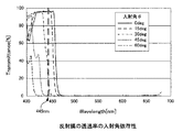
反射膜31を例えば図3に示すようなダイクロイックミラーで構成した場合には、各誘電体層の積層数、各誘電体層の厚さ、各誘電体層の形成材料等を調整することにより、反射膜31に入射する光の透過率(反射率)の入射角依存性を設定しやすくなる。図4に、本実施形態で用いる反射膜31の光透過率の入射角依存性の一例を示す。図4に示す特性の横軸は入射光の波長であり、縦軸は透過率である。
When the
図4に示す例では、反射膜31は、赤色光及び緑色光を含む波長帯域(約480〜680nmに渡る波長領域)の光を、その入射角θに関係なく選択的に反射するように設計されている。それゆえ、赤色光及び緑色光を含む波長帯域の光(蛍光体層32からの発光光)に対しては、その光の入射角θに関係なく、透過率が略零となる。すなわち、赤色光及び緑色光を含む波長領域の光は、入射角θに関係なく、反射膜31で全て反射される。
In the example shown in FIG. 4, the
一方、波長445nmの青色光(励起光L)に対しては、その入射角θが約20度以下であるときに青色光が透過し、入射角θが約20度より大きい場合には青色光が反射されるように、反射膜31が設計されている。それゆえ、図4に示すように、青色光(励起光L)の波長445nm(太破線)では、光の入射角θが0度(実線)及び15度(破線)の時は、透過率が大きくなる。また、青色光の入射角θが30度(一点鎖線)、45度(点線)及び60度(二点鎖線)の時は、波長445nmにおける透過率が小さくなる。すなわち、蛍光体層32内で散乱及び反射された励起光Lのうち、約20度より大きな入射角θで反射膜31に入射する励起光成分は、反射膜31で第2集光光学系15に向かう方向に反射される。
On the other hand, for blue light (excitation light L) having a wavelength of 445 nm, blue light is transmitted when the incident angle θ is approximately 20 degrees or less, and blue light is transmitted when the incident angle θ is greater than approximately 20 degrees. The
なお、上述のように、反射膜31の透過率の入射角依存性に応じて第1集光光学系12の構成が設計される。例えば、反射膜31が、図4に示すような透過率の入射角依存性を有する場合には、励起光Lの利用効率を低下させないために、集光された励起光Lの入射角θが、約20度以下になるように、第1集光光学系12が設計される。
Note that, as described above, the configuration of the first condensing optical system 12 is designed according to the incident angle dependency of the transmittance of the
蛍光体層32は、励起光Lの入射により、所定波長帯域の光を発光する層状の蛍光体である。本実施形態では、励起光Lの透過光と蛍光体層32での発光光とを合波して白色光LWを生成するので、蛍光体層32としては、例えばYAG(Yttrium Aluminum Garnet)系蛍光材料等で形成する。この場合、青色の励起光Lが入射されると、蛍光体層32からは波長480〜680nmの帯域の光(黄色光)が発光される。なお、蛍光体層32としては、赤色光及び緑色光を含む波長帯域の光を発光する膜であれば、任意の材料で構成することができるが、発光効率及び耐熱性の観点ではYAG系蛍光体材料を用いることが好ましい。
The
また、蛍光体層32は、蛍光材料とバインダとを混合した所定の蛍光剤を反射膜31上に塗布することにより形成される。図2(a)〜(c)に示す例では蛍光体層32を反射膜31の全面に渡って形成するので、蛍光体層32の表面形状もドーナッツ状となる。なお、蛍光体層32は、励起光Lが入射される領域に形成されていればよいので、蛍光体層32の形状は、図2(a)〜(c)に示す例に限定されず、例えば、蛍光体層32の半径方向の幅が、反射膜31のそれより狭くてもよい。
The
また、蛍光体層32での発光量及び励起光Lの透過量は、例えば蛍光体層32の厚さや蛍光体密度(含有量)等により調整することができる。それゆえ、本実施形態では、光源装置部1からの出射光が白色光となるように、蛍光体層32の厚さや蛍光体密度等を調整する。
Further, the light emission amount and the transmission amount of the excitation light L in the
反射防止膜33は、透明基板30の励起光Lの入射側表面に設けられ、励起光Lの集光光を蛍光部材13に入射した際に、その入射面で発生する励起光Lの反射を防止する。これにより、励起光Lの利用効率を向上させることができる。
The
なお、上記実施形態では、蛍光部材13に、反射膜31及び反射防止膜33を設ける例を説明したが、本発明はこれに限定されない。例えば、光源装置部1からの出射光の出力が小さくても問題のない用途等に本実施形態の光源装置部1を適用する場合には、反射膜31及び反射防止膜33のいずれか一方又は両方を備えない構成にしてもよい。さらに、上記実施形態の蛍光部材13では、透明基板30上に反射膜31を介して層状の蛍光体(蛍光体層32)を設ける例を説明したが、本発明はこれに限定されない。例えば、蛍光体を十分な剛性を有する板状部材で構成した場合には、透明基板30を設けなくてもよい。
In the above embodiment, the example in which the
[4.光源装置部の動作例]
図5に、本実施形態の光源装置部1の動作の様子を示す。本実施形態の光源装置部1では、まず、励起光源11から射出された励起光L(この例では青色光)を、第1集光光学系12で集光する。そして、その集光光(集光された励起光L)は、蛍光部材13の反射防止膜33側から所定の入射角θで蛍光部材13に入射される。なお、本実施形態では、モータ14により、蛍光部材13を所定の回転数で回転させた状態で、集光光を蛍光部材13に照射する。
[4. Example of operation of light source unit]
FIG. 5 shows the operation of the light
蛍光部材13に入射された集光光は、反射防止膜33、透明基板30及び反射膜31を通過して蛍光体層32に入射される。なお、上述のように、反射膜31は、所定の入射角θ以下の励起光Lを透過するように設計されているので、蛍光部材13に入射された集光光は、反射膜31で反射されない。
The condensed light incident on the fluorescent member 13 passes through the
そして、集光光(励起光L)が蛍光体層32に入射されると、その一部は、蛍光体層32を通過するが、残りは、主に、蛍光体層32で吸収される。この吸収された励起光Lにより、蛍光体層32が励起され、蛍光体層32から所定波長帯域の光(この例では赤色光及び緑色光を含む黄色光)が発光する。この結果、励起光Lの透過成分と、蛍光体層32からの発光光とが合波され、蛍光体層32から白色光が射出される。
When condensed light (excitation light L) is incident on the
なお、この際、蛍光体層32の発光光は、第2集光光学系15に向かう方向だけでなく、透明基板30に向かう方向にも射出される。また、蛍光体層32に入射された励起光Lの一部は、蛍光体層32内で透明基板30に向かう方向にも散乱及び反射される。しかしながら、本実施形態の蛍光部材13では、上述のように、透明基板30と蛍光体層32との間に反射膜31を設けているので、透明基板30に向かう方向に射出された発光光及び励起光成分は、反射膜31により第2集光光学系15に向かう方向に反射される。この際、反射膜31で反射された励起光成分は、蛍光体層32で吸収され、さらに蛍光体層32を発光させる。それゆえ、本実施形態のように、透明基板30と蛍光体層32との間に反射膜31を設けた場合には、励起光Lの利用効率を向上させることができ、発光光の光量をより増大させることができる。
At this time, the light emitted from the
また、実際に、本発明者は、光源装置部1の各部のパラメータを次のように設定して、光源装置部1からの出射光のスペクトル特性を調べた。
励起光源11(青色レーザ)の波長:445nm
励起光Lの集光径:1mm
励起光Lの入射角θ:20度以下
蛍光部材13の回転数:3000rpm
第2集光光学系15及び蛍光体層32間の距離:1mm以下
透明基板30の形成材料:ガラス
透明基板30の直径:30mm
反射膜31の透過特性:図4に示す特性
蛍光体層32の形成材料:YAG系蛍光体
蛍光体層32の厚さ:50μm
蛍光体層32の幅:5mm
Actually, the present inventor set the parameters of each part of the light
Wavelength of excitation light source 11 (blue laser): 445 nm
Condensing diameter of excitation light L: 1 mm
Incident angle θ of excitation light L: 20 degrees or less Number of rotations of fluorescent member 13: 3000 rpm
Distance between second condensing optical system 15 and phosphor layer 32: 1 mm or less Forming material of transparent substrate 30: Glass Diameter of transparent substrate 30: 30 mm
Transmission characteristics of the reflective film 31: characteristics shown in FIG. 4 Material for forming the phosphor layer 32: YAG-based phosphor Thickness of the phosphor layer 32: 50 μm
Width of phosphor layer 32: 5 mm
図6に、上記条件で得られた光源装置部1からの出射光のスペクトル特性を示す。なお、図6に示す特性では、横軸が波長であり、縦軸が出射光の強度(任意単位)である。図6から明らかなように、上記条件では、出射光に、波長445nm付近の光成分(青色光成分)と、約480〜680nmに渡る波長領域の光成分、すなわち、赤色光成分及び緑色光成分を含む光成分とが含まれていることが分かる。このことからも、本実施形態の光源装置部1から、白色光LWが出射されていることが分かる。
FIG. 6 shows the spectral characteristics of the emitted light from the
上述のように、本実施形態では、固体発光素子を用いて白色光を光源装置部1から射出することができる。それゆえ、本実施形態は、例えば3LCD方式のプロジェクタ等のように、白色光を射出する光源装置を必要とする用途にも適用可能である。すなわち、本実施形態では、様々な用途に適用可能な水銀レスの光源装置部1(照明装置)及びそれを備える画像表示装置10を提供することができる。
As described above, in the present embodiment, white light can be emitted from the light
本実施形態の光源装置部1は、水銀ランプを用いる必要が無いので、近年の環境問題に対応することができる。また、本実施形態では、水銀ランプに比べてより長寿命で且つ輝度低下も小さい光源装置部1及び画像表示装置10を提供することができる。さらに、本実施形態のように、励起光源11に固体発光素子を用いた場合には、水銀ランプに比べて点灯時間をより短縮することができる。
Since the light
また、本実施形態の光源装置部1のように励起光源11として半導体レーザを用いた場合には、例えばLED(Light Emitting Diode)等の固体光源に比べても、十分高輝度の光を射出することができ、高輝度光源の実現が可能になる。さらに、本実施形態のように、青色光レーザで蛍光体層32を発光させて白色光LWを生成する構成は、赤色光、緑色光及び青色光の各固体光源を個別に用意して白色光を生成する構成に比べてより安価である。
Further, when a semiconductor laser is used as the excitation light source 11 as in the light
上記実施形態では、光源装置部1(照明装置)を3LCD方式のプロジェクタに適用する例を説明したが、本発明はこれに限定されず、白色光を必要とする任意の画像表示装置に適用可能であり、同様の効果が得られる。 In the above embodiment, the example in which the light source device unit 1 (illumination device) is applied to a 3LCD projector has been described, but the present invention is not limited to this, and can be applied to any image display device that requires white light. The same effect can be obtained.
また、上記実施形態では、光源装置部1(照明装置)の出射光を白色光とする例を説明したが、本発明はこれに限定されない。例えば、出射光としてシアン光(またはマゼンダ光)を必要とする用途では、励起光Lとして青色光を用い、蛍光体層32を緑色光(または赤色光)のみを発光する蛍光材料で形成すればよい。すなわち、必要とする出射光の波長(色)に応じて、励起光Lの波長と蛍光体層32の形成材料との組み合わせを適宜選択すればよい。
Moreover, although the said embodiment demonstrated the example which made the emitted light of the light source device part 1 (illuminating device) white light, this invention is not limited to this. For example, in applications that require cyan light (or magenta light) as the emitted light, blue light is used as the excitation light L, and the
1…光源装置部(照明装置)、2…光学エンジン部(画像投影部)、10…画像表示装置、11…励起光源、12…第1集光光学系、13…蛍光部材、14…モータ、15…第2集光光学系、20…分光光学系、21…第1LCDパネル、22…第2LCDパネル、23…第3LCDパネル、24…プリズム、25…投影光学系、30…透明基板、31…反射膜、32…蛍光体層(蛍光体)、33…反射防止膜
DESCRIPTION OF
Claims (7)
前記励起光が照射された際に、前記第1の波長より長い第2の波長を有する光を発光するとともに、前記励起光の一部を透過させて、該透過した前記第1の波長の励起光と該発光した第2の波長の光とを合波して射出し、且つ、回転する基板の回転円周方向に沿って前記基板上に連続して形成されるとともに、前記基板の中心を回転軸として回転可能な単一の蛍光体と、
前記蛍光体の前記励起光の入射側に設けられ、所定角度以下の入射角の励起光を透過するとともに前記蛍光体で発光した光を反射する反射膜と、
前記蛍光体の前記励起光の入射側に設けられ、前記励起光の反射を防止する反射防止膜と、
前記反射膜及び前記励起光源間の光路上に設けられ、前記励起光を集光する第1光学系と、
前記基板の中心に駆動軸が接続され、前記蛍光体に照射される前記励起光の照射位置を時間とともに前記基板の回転円周方向へ移動させるよう前記基板を回転させる駆動部と、を備え、
前記蛍光体は、前記駆動部が前記基板を回転させることにより移動する前記照射位置において単一であり、
前記第1光学系で集光され前記反射防止膜を通過した励起光の前記反射膜への入射角が、前記所定角度以下となるよう構成される光源装置。 An excitation light source that emits excitation light having a first wavelength;
When irradiated with the excitation light, it emits light having a second wavelength longer than the first wavelength, transmits a part of the excitation light, and transmits the excitation of the transmitted first wavelength. The light and the emitted light of the second wavelength are combined and emitted, and continuously formed on the substrate along the rotation circumferential direction of the rotating substrate, and the center of the substrate is A single phosphor rotatable as a rotation axis;
A reflective film that is provided on the excitation light incident side of the phosphor, transmits excitation light having an incident angle of a predetermined angle or less, and reflects light emitted from the phosphor;
An antireflection film that is provided on the excitation light incident side of the phosphor and prevents reflection of the excitation light;
A first optical system that is provided on an optical path between the reflection film and the excitation light source and collects the excitation light;
A drive unit connected to the center of the substrate and rotating the substrate to move the irradiation position of the excitation light irradiated to the phosphor in the rotation circumferential direction of the substrate with time, and
The phosphor Ri single der at the irradiation position where the drive unit is moved by rotating the substrate,
A light source device configured such that an incident angle of the excitation light collected by the first optical system and passing through the antireflection film is not more than the predetermined angle .
請求項1に記載の光源装置。 The light source device according to claim 1 , wherein the reflection film is a film that transmits excitation light having an incident angle of 20 degrees or less.
請求項1に記載の光源装置。 The light source device according to claim 1, further comprising a second optical system that converts light emitted from the phosphor into parallel light.
請求項1に記載の光源装置。 The light source device according to claim 1, wherein the first wavelength is a blue wavelength, and the second wavelength is a wavelength band including red and green wavelengths.
請求項1に記載の光源装置。 The light source device according to claim 1, wherein the driving unit moves the phosphor in a predetermined direction within a surface irradiated with the excitation light of the phosphor.
前記蛍光体の前記励起光の入射側に設けられ、所定角度以下の入射角の励起光を透過するとともに前記蛍光体で発光した光を反射する反射膜と、
前記蛍光体の前記励起光の入射側に設けられ、前記励起光の反射を防止する反射防止膜と、
前記反射膜及び前記励起光源間の光路上に設けられ、前記励起光を集光する第1光学系と、
前記基板の中心に駆動軸が接続され、前記蛍光体に照射される前記励起光の照射位置を時間とともに前記基板の回転円周方向へ移動させるよう前記基板を回転させる駆動部と、を有する光源装置部と、
前記光源装置部から射出された光を用いて所定の画像光を生成し、該生成した画像光を外部に投影する画像投影部と、を備え、
前記蛍光体は、前記駆動部が前記基板を回転させることにより移動する前記照射位置において単一であり、
前記第1光学系で集光され前記反射防止膜を通過した励起光の前記反射膜への入射角が、前記所定角度以下となるよう構成される画像投影装置。 A pumping light source that emits pumping light having a first wavelength; and a portion of the pumping light that emits light having a second wavelength longer than the first wavelength when the pumping light is irradiated. The transmitted excitation light of the first wavelength and the emitted light of the second wavelength are combined and emitted, and continuously along the rotation circumferential direction of the rotating substrate. And a single phosphor that can be rotated about the center of the substrate as a rotation axis;
A reflective film that is provided on the excitation light incident side of the phosphor, transmits excitation light having an incident angle of a predetermined angle or less, and reflects light emitted from the phosphor;
An antireflection film that is provided on the excitation light incident side of the phosphor and prevents reflection of the excitation light;
A first optical system that is provided on an optical path between the reflection film and the excitation light source and collects the excitation light;
A light source having a drive shaft connected to the center of the substrate and rotating the substrate so that the irradiation position of the excitation light irradiated to the phosphor moves with time in the rotation circumferential direction of the substrate; A device section;
An image projection unit that generates predetermined image light using light emitted from the light source device unit, and projects the generated image light to the outside;
The phosphor Ri single der at the irradiation position where the drive unit is moved by rotating the substrate,
An image projection apparatus configured such that an excitation angle of excitation light collected by the first optical system and passing through the antireflection film is not more than the predetermined angle .
請求項6に記載の画像投影装置。 The image projection apparatus according to claim 6 , wherein the reflection film is a film that transmits excitation light having an incident angle of 20 degrees or less.
Priority Applications (11)
| Application Number | Priority Date | Filing Date | Title |
|---|---|---|---|
| JP2010137192A JP5767444B2 (en) | 2010-06-16 | 2010-06-16 | Light source device and image projection device |
| TW100119372A TWI421448B (en) | 2010-06-16 | 2011-06-02 | Illumination device and image display apparatus |
| KR1020110054984A KR20110137245A (en) | 2010-06-16 | 2011-06-08 | Illumination device and image display apparatus |
| US13/156,744 US9052582B2 (en) | 2010-06-16 | 2011-06-09 | Illumination device and image display apparatus |
| CN201110152826.6A CN102289140B (en) | 2010-06-16 | 2011-06-09 | Illuminating device and image display device |
| US14/695,396 US9369682B2 (en) | 2010-06-16 | 2015-04-24 | Illumination device and image display apparatus |
| US15/075,428 US9618738B2 (en) | 2010-06-16 | 2016-03-21 | Illumination device and image display apparatus |
| US15/380,435 US9733558B2 (en) | 2010-06-16 | 2016-12-15 | Illumination device and image display apparatus |
| US15/482,969 US9995927B2 (en) | 2010-06-16 | 2017-04-10 | Illumination device and image display apparatus |
| KR1020170059777A KR101973262B1 (en) | 2010-06-16 | 2017-05-15 | Light source device and image display apparatus |
| US15/960,892 US10429636B2 (en) | 2010-06-16 | 2018-04-24 | Illumination device and image display apparatus |
Applications Claiming Priority (1)
| Application Number | Priority Date | Filing Date | Title |
|---|---|---|---|
| JP2010137192A JP5767444B2 (en) | 2010-06-16 | 2010-06-16 | Light source device and image projection device |
Related Child Applications (1)
| Application Number | Title | Priority Date | Filing Date |
|---|---|---|---|
| JP2015123652A Division JP6279516B2 (en) | 2015-06-19 | 2015-06-19 | Light source device and image projection device |
Publications (3)
| Publication Number | Publication Date |
|---|---|
| JP2012003923A JP2012003923A (en) | 2012-01-05 |
| JP2012003923A5 JP2012003923A5 (en) | 2013-07-25 |
| JP5767444B2 true JP5767444B2 (en) | 2015-08-19 |
Family
ID=45328370
Family Applications (1)
| Application Number | Title | Priority Date | Filing Date |
|---|---|---|---|
| JP2010137192A Active JP5767444B2 (en) | 2010-06-16 | 2010-06-16 | Light source device and image projection device |
Country Status (5)
| Country | Link |
|---|---|
| US (6) | US9052582B2 (en) |
| JP (1) | JP5767444B2 (en) |
| KR (2) | KR20110137245A (en) |
| CN (1) | CN102289140B (en) |
| TW (1) | TWI421448B (en) |
Cited By (2)
| Publication number | Priority date | Publication date | Assignee | Title |
|---|---|---|---|---|
| KR20190010549A (en) | 2016-05-24 | 2019-01-30 | 소니 주식회사 | Light source device and projection display device |
| US10551031B2 (en) | 2016-05-20 | 2020-02-04 | Sony Corporation | Light source apparatus and projection display apparatus |
Families Citing this family (62)
| Publication number | Priority date | Publication date | Assignee | Title |
|---|---|---|---|---|
| JP5767444B2 (en) * | 2010-06-16 | 2015-08-19 | ソニー株式会社 | Light source device and image projection device |
| US10310363B2 (en) | 2011-09-22 | 2019-06-04 | Delta Electronics, Inc. | Phosphor device with spectrum of converted light comprising at least a color light |
| TWI448806B (en) | 2011-09-22 | 2014-08-11 | Delta Electronics Inc | Phosphor device and illumination system and projection equipment with the same |
| US10688527B2 (en) | 2011-09-22 | 2020-06-23 | Delta Electronics, Inc. | Phosphor device comprising plural phosphor agents for converting waveband light into plural color lights with different wavelength peaks |
| WO2013046243A1 (en) * | 2011-09-26 | 2013-04-04 | 日立コンシューマエレクトロニクス株式会社 | Light source apparatus |
| CN103186021B (en) * | 2011-12-27 | 2016-01-20 | 台达电子工业股份有限公司 | Light-source system and Wavelength converter thereof |
| CN102723422B (en) * | 2011-12-31 | 2015-04-29 | 深圳市光峰光电技术有限公司 | Wavelength conversion apparatus and luminous apparatus |
| CN102854723B (en) * | 2012-01-07 | 2015-02-04 | 深圳市光峰光电技术有限公司 | Light-emitting device and projection apparatus |
| JP2013162021A (en) * | 2012-02-07 | 2013-08-19 | Seiko Epson Corp | Wavelength conversion element, light source device, and projector |
| JP2013162020A (en) | 2012-02-07 | 2013-08-19 | Seiko Epson Corp | Wavelength conversion element, light source device, and projector |
| CN103376634B (en) | 2012-04-24 | 2015-11-18 | 中强光电股份有限公司 | Light source module and projection arrangement |
| JP5962904B2 (en) | 2012-04-26 | 2016-08-03 | パナソニックIpマネジメント株式会社 | Light source device and projection display device including the light source device |
| JP6270012B2 (en) * | 2012-09-20 | 2018-01-31 | カシオ計算機株式会社 | Light source device, lighting method of light source device, and projector |
| JP6086193B2 (en) | 2012-09-20 | 2017-03-01 | カシオ計算機株式会社 | Light source device, lighting method of light source device, and projector |
| JP2014203852A (en) * | 2013-04-01 | 2014-10-27 | 日本電気硝子株式会社 | Wavelength conversion member and light emitting device |
| WO2014174559A1 (en) * | 2013-04-22 | 2014-10-30 | 日立マクセル株式会社 | Light source apparatus and image display apparatus |
| JP2014235250A (en) * | 2013-05-31 | 2014-12-15 | ソニー株式会社 | Light source device and projector |
| JP2015034867A (en) * | 2013-08-08 | 2015-02-19 | 日本電気硝子株式会社 | Projector fluorescent wheel and projector light-emitting device |
| JP2015034866A (en) * | 2013-08-08 | 2015-02-19 | 日本電気硝子株式会社 | Projector fluorescent wheel and projector light-emitting device |
| TWI509344B (en) | 2013-09-18 | 2015-11-21 | Coretronic Corp | Illumination system and projection apparatus |
| TWI524129B (en) | 2013-11-21 | 2016-03-01 | 中強光電股份有限公司 | Illumination system and projection apparatus |
| TW201528379A (en) * | 2013-12-20 | 2015-07-16 | Applied Materials Inc | Dual wavelength annealing method and apparatus |
| CN104765237B (en) * | 2014-01-03 | 2016-08-17 | 台达电子工业股份有限公司 | Optical projection apparatus |
| JP6195321B2 (en) * | 2014-01-08 | 2017-09-13 | Necディスプレイソリューションズ株式会社 | Light source device and projection display device |
| JP2015163947A (en) | 2014-02-03 | 2015-09-10 | キヤノン株式会社 | Light source optical system, light source device having the same, and image display device |
| JP2015155958A (en) * | 2014-02-20 | 2015-08-27 | セイコーエプソン株式会社 | Illumination device and projector |
| JP2015166787A (en) * | 2014-03-04 | 2015-09-24 | カシオ計算機株式会社 | Light source device and projection device |
| JP6225812B2 (en) | 2014-04-18 | 2017-11-08 | 日亜化学工業株式会社 | Light emitting device |
| JP6458390B2 (en) * | 2014-07-31 | 2019-01-30 | 日亜化学工業株式会社 | Light source device and projector provided with the light source device |
| CN104174992B (en) * | 2014-08-26 | 2016-04-13 | 济南金威刻科技发展有限公司 | Mixing cutting machine generating device of laser |
| JP6507548B2 (en) * | 2014-09-26 | 2019-05-08 | セイコーエプソン株式会社 | Wavelength conversion element, light source device, projector |
| US10067413B2 (en) * | 2014-10-28 | 2018-09-04 | Sony Corporation | Light source device and projector |
| CN105629486B (en) * | 2014-10-28 | 2019-03-29 | 深圳光峰科技股份有限公司 | 3D projection display system |
| JP6489831B2 (en) * | 2015-01-07 | 2019-03-27 | スタンレー電気株式会社 | Wavelength converter, method for manufacturing the same, and illumination device using the wavelength converter |
| WO2016116975A1 (en) * | 2015-01-20 | 2016-07-28 | ソニー株式会社 | Light source device, image display device, and light source module |
| CN105988274A (en) * | 2015-03-20 | 2016-10-05 | 台达电子工业股份有限公司 | Optical device |
| WO2016181858A1 (en) * | 2015-05-08 | 2016-11-17 | コニカミノルタ株式会社 | Light source device and projection device |
| JP6536212B2 (en) * | 2015-06-23 | 2019-07-03 | セイコーエプソン株式会社 | Wavelength conversion element, light source device and projector |
| CN106896632A (en) * | 2015-12-03 | 2017-06-27 | 精工爱普生株式会社 | Fluorophor, Wavelength changing element, light supply apparatus and projecting apparatus |
| JP2017123317A (en) * | 2016-01-08 | 2017-07-13 | パナソニックIpマネジメント株式会社 | Luminaire |
| CN107193177B (en) * | 2016-03-14 | 2020-11-17 | 深圳光峰科技股份有限公司 | Light source system and projection device thereof |
| CN105915871A (en) * | 2016-05-09 | 2016-08-31 | 南京熊猫电子股份有限公司 | Laser TV full-color generation method and device in 3 LCD mode |
| GB2568171B (en) | 2016-06-01 | 2021-11-03 | Canon Kk | Wavelength conversion element, light source apparatus, and image projection apparatus |
| JP2016194709A (en) * | 2016-06-23 | 2016-11-17 | セイコーエプソン株式会社 | Light source device and projector |
| JP2018028647A (en) * | 2016-08-20 | 2018-02-22 | セイコーエプソン株式会社 | Wavelength conversion element, light source device, and projector |
| WO2018042849A1 (en) * | 2016-08-30 | 2018-03-08 | ソニー株式会社 | Projection display device |
| CN110300849B (en) * | 2017-02-22 | 2021-10-15 | 西门子歌美飒可再生能源公司 | Tower for a wind turbine and wind turbine |
| JP6916073B2 (en) * | 2017-02-28 | 2021-08-11 | パナソニック株式会社 | Optical device |
| JP6926589B2 (en) * | 2017-03-29 | 2021-08-25 | セイコーエプソン株式会社 | Light source device and projector |
| CN109917610B (en) | 2017-12-12 | 2020-12-01 | 中强光电股份有限公司 | Light source module and projection device |
| CN111566558B (en) * | 2018-01-19 | 2022-02-01 | 索尼公司 | Light source device and projection display device |
| JP7198978B2 (en) * | 2018-04-27 | 2023-01-05 | パナソニックIpマネジメント株式会社 | Phosphor wheel, light source device and projection display device |
| CN110505461B (en) * | 2018-05-18 | 2022-07-29 | 深圳Tcl新技术有限公司 | Laser projection television |
| WO2019231080A1 (en) * | 2018-05-30 | 2019-12-05 | 액츠 주식회사 | Light source device and image projection device comprising same |
| US11781737B2 (en) | 2018-11-26 | 2023-10-10 | Kyocera Corporation | Light source device and lighting device |
| CN110213471B (en) * | 2019-06-28 | 2021-01-08 | 维沃移动通信(杭州)有限公司 | Terminal device |
| JP7071702B2 (en) * | 2019-07-22 | 2022-05-19 | カシオ計算機株式会社 | Light source device and projection device |
| JP7283327B2 (en) * | 2019-09-20 | 2023-05-30 | セイコーエプソン株式会社 | Wavelength conversion element, light source device and projector |
| JP7294089B2 (en) * | 2019-11-28 | 2023-06-20 | セイコーエプソン株式会社 | Light source device and projector |
| CN114613253B (en) * | 2020-12-09 | 2024-01-23 | 极米科技股份有限公司 | Optical system and display device |
| JP2022112948A (en) | 2021-01-22 | 2022-08-03 | セイコーエプソン株式会社 | Light source device and projector |
| JP2022149550A (en) * | 2021-03-25 | 2022-10-07 | セイコーエプソン株式会社 | Wavelength converter, light source device, projector, and method for manufacturing wavelength converter |
Family Cites Families (44)
| Publication number | Priority date | Publication date | Assignee | Title |
|---|---|---|---|---|
| JPH06265894A (en) | 1993-03-11 | 1994-09-22 | Teruki Fujiyama | Color display device |
| CA2171961A1 (en) | 1993-09-17 | 1995-03-23 | David Kappel | Compact projection illumination system and method of using same |
| JP4182804B2 (en) | 2003-04-28 | 2008-11-19 | セイコーエプソン株式会社 | Illumination device and projection display device |
| JP4829470B2 (en) * | 2003-05-14 | 2011-12-07 | Necディスプレイソリューションズ株式会社 | Projection display |
| CN1624570A (en) * | 2003-12-03 | 2005-06-08 | 精工爱普生株式会社 | Projector |
| US7431463B2 (en) * | 2004-03-30 | 2008-10-07 | Goldeneye, Inc. | Light emitting diode projection display systems |
| TWI398188B (en) * | 2004-08-31 | 2013-06-01 | Showa Denko Kk | A luminous body, and a lighting and display device using the luminous body |
| TWI254821B (en) * | 2004-10-01 | 2006-05-11 | Delta Electronics Inc | Backlight module |
| JP2006119440A (en) * | 2004-10-22 | 2006-05-11 | Olympus Corp | Surface sequential illuminating apparatus and image projecting apparatus |
| US7391569B2 (en) * | 2004-12-29 | 2008-06-24 | 3M Innovative Properties Company | Projection system including intrinsic polarizer |
| US8269410B2 (en) * | 2005-03-18 | 2012-09-18 | Mitsubishi Chemical Corporation | Light-emitting device, white light-emitting device, illuminator, and image display |
| FR2883645A1 (en) | 2005-03-22 | 2006-09-29 | Thomson Licensing Sa | IMAGING SYSTEM FOR PROJECTOR AND CORRESPONDING PROJECTOR |
| US7445340B2 (en) * | 2005-05-19 | 2008-11-04 | 3M Innovative Properties Company | Polarized, LED-based illumination source |
| WO2006133214A2 (en) | 2005-06-07 | 2006-12-14 | Optical Research Associates | Phosphor wheel illuminator |
| JP4910315B2 (en) * | 2005-06-20 | 2012-04-04 | セイコーエプソン株式会社 | Display device and light emitting device |
| US7543959B2 (en) * | 2005-10-11 | 2009-06-09 | Philips Lumiled Lighting Company, Llc | Illumination system with optical concentrator and wavelength converting element |
| JP2007109947A (en) * | 2005-10-14 | 2007-04-26 | Toyoda Gosei Co Ltd | Phosphor plate and light-emitting device provided with the same |
| US7369320B2 (en) * | 2005-12-30 | 2008-05-06 | 3M Innovative Properties Company | Projection system with beam homogenizer |
| US20070187580A1 (en) | 2006-02-14 | 2007-08-16 | Microvision, Inc. | Photoluminescent light sources, and scanned beam systems and methods of using same |
| US7682850B2 (en) * | 2006-03-17 | 2010-03-23 | Philips Lumileds Lighting Company, Llc | White LED for backlight with phosphor plates |
| US7889430B2 (en) * | 2006-05-09 | 2011-02-15 | Ostendo Technologies, Inc. | LED-based high efficiency illumination systems for use in projection systems |
| JP2008052070A (en) | 2006-08-25 | 2008-03-06 | Samsung Electronics Co Ltd | Color wheel, visible light source, and projection image display device and method |
| US7547114B2 (en) * | 2007-07-30 | 2009-06-16 | Ylx Corp. | Multicolor illumination device using moving plate with wavelength conversion materials |
| JP2009042569A (en) * | 2007-08-09 | 2009-02-26 | Panasonic Corp | Projection type display |
| US20090051884A1 (en) * | 2007-08-21 | 2009-02-26 | United Microelectronics Corp. | Projection apparatus |
| CN101498401B (en) * | 2008-01-29 | 2011-08-03 | 绎立锐光科技开发(深圳)有限公司 | Light source structure for improving light conversion efficiency by fluorescent powder |
| US8471283B2 (en) * | 2008-02-25 | 2013-06-25 | Kabushiki Kaisha Toshiba | White LED lamp, backlight, light emitting device, display device and illumination device |
| JP2009245712A (en) * | 2008-03-31 | 2009-10-22 | Stanley Electric Co Ltd | Illumination fixture |
| US8764198B2 (en) * | 2008-04-29 | 2014-07-01 | Himax Display, Inc. | Projection system having rotationally asymmetrical illumination unit for emitting light along optic axis |
| JP4662185B2 (en) * | 2008-05-15 | 2011-03-30 | カシオ計算機株式会社 | Light source device and projector |
| JP5527571B2 (en) * | 2008-09-30 | 2014-06-18 | カシオ計算機株式会社 | Light emitting device, light source device, and projector using the light source device |
| JP5152586B2 (en) * | 2008-09-30 | 2013-02-27 | カシオ計算機株式会社 | Light source device and projector |
| JP5431706B2 (en) * | 2008-10-01 | 2014-03-05 | ミネベア株式会社 | Light emitting device |
| CN201417358Y (en) * | 2009-02-20 | 2010-03-03 | 红蝶科技(深圳)有限公司 | Miniature projection optical engine with high lighting effect |
| CN101825836A (en) * | 2009-03-02 | 2010-09-08 | 鸿富锦精密工业(深圳)有限公司 | Light source system |
| JP4678556B2 (en) * | 2009-03-17 | 2011-04-27 | カシオ計算機株式会社 | Light emitting device, light source device, and projector using the light source device |
| JP4711154B2 (en) * | 2009-06-30 | 2011-06-29 | カシオ計算機株式会社 | Light source device and projector |
| JP4756403B2 (en) * | 2009-06-30 | 2011-08-24 | カシオ計算機株式会社 | Light source device and projector |
| US8684560B2 (en) * | 2009-11-18 | 2014-04-01 | Stanley Electric Co., Ltd. | Semiconductor light source apparatus and lighting unit |
| US8556437B2 (en) | 2009-12-17 | 2013-10-15 | Stanley Electric Co., Ltd. | Semiconductor light source apparatus and lighting unit |
| JP5567844B2 (en) * | 2010-01-29 | 2014-08-06 | 日立コンシューマエレクトロニクス株式会社 | Projection display device |
| JP5617288B2 (en) * | 2010-03-18 | 2014-11-05 | セイコーエプソン株式会社 | Lighting device and projector |
| JP5767444B2 (en) * | 2010-06-16 | 2015-08-19 | ソニー株式会社 | Light source device and image projection device |
| JP5770433B2 (en) * | 2010-06-18 | 2015-08-26 | ソニー株式会社 | Light source device and image projection device |
-
2010
- 2010-06-16 JP JP2010137192A patent/JP5767444B2/en active Active
-
2011
- 2011-06-02 TW TW100119372A patent/TWI421448B/en active
- 2011-06-08 KR KR1020110054984A patent/KR20110137245A/en active Search and Examination
- 2011-06-09 US US13/156,744 patent/US9052582B2/en active Active
- 2011-06-09 CN CN201110152826.6A patent/CN102289140B/en active Active
-
2015
- 2015-04-24 US US14/695,396 patent/US9369682B2/en active Active
-
2016
- 2016-03-21 US US15/075,428 patent/US9618738B2/en active Active
- 2016-12-15 US US15/380,435 patent/US9733558B2/en active Active
-
2017
- 2017-04-10 US US15/482,969 patent/US9995927B2/en active Active
- 2017-05-15 KR KR1020170059777A patent/KR101973262B1/en active IP Right Grant
-
2018
- 2018-04-24 US US15/960,892 patent/US10429636B2/en active Active
Cited By (3)
| Publication number | Priority date | Publication date | Assignee | Title |
|---|---|---|---|---|
| US10551031B2 (en) | 2016-05-20 | 2020-02-04 | Sony Corporation | Light source apparatus and projection display apparatus |
| KR20190010549A (en) | 2016-05-24 | 2019-01-30 | 소니 주식회사 | Light source device and projection display device |
| US11156907B2 (en) | 2016-05-24 | 2021-10-26 | Sony Corporation | Light source apparatus and projection display apparatus |
Also Published As
| Publication number | Publication date |
|---|---|
| US9733558B2 (en) | 2017-08-15 |
| US20180239126A1 (en) | 2018-08-23 |
| US10429636B2 (en) | 2019-10-01 |
| TWI421448B (en) | 2014-01-01 |
| JP2012003923A (en) | 2012-01-05 |
| US9995927B2 (en) | 2018-06-12 |
| US9369682B2 (en) | 2016-06-14 |
| US20170212414A1 (en) | 2017-07-27 |
| KR20170056494A (en) | 2017-05-23 |
| US9618738B2 (en) | 2017-04-11 |
| TW201235618A (en) | 2012-09-01 |
| US9052582B2 (en) | 2015-06-09 |
| US20170097561A1 (en) | 2017-04-06 |
| US20150229891A1 (en) | 2015-08-13 |
| CN102289140B (en) | 2016-08-03 |
| US20110310362A1 (en) | 2011-12-22 |
| US20160202468A1 (en) | 2016-07-14 |
| KR101973262B1 (en) | 2019-08-16 |
| CN102289140A (en) | 2011-12-21 |
| KR20110137245A (en) | 2011-12-22 |
Similar Documents
| Publication | Publication Date | Title |
|---|---|---|
| JP5767444B2 (en) | Light source device and image projection device | |
| JP5770433B2 (en) | Light source device and image projection device | |
| JP6137238B2 (en) | Light source device and image projection device | |
| JP6149991B2 (en) | Light source device and image projection device | |
| JP6388051B2 (en) | Light source device and image projection device | |
| JP6819759B2 (en) | Light source device and image projection device | |
| JP6353583B2 (en) | Light source device and image projection device | |
| JP6453495B2 (en) | Light source device and image projection device | |
| JP6279516B2 (en) | Light source device and image projection device | |
| JP6680340B2 (en) | Light source device and image projection device | |
| JP6680312B2 (en) | Light source device and image projection device |
Legal Events
| Date | Code | Title | Description |
|---|---|---|---|
| A521 | Request for written amendment filed |
Free format text: JAPANESE INTERMEDIATE CODE: A523 Effective date: 20130611 |
|
| A621 | Written request for application examination |
Free format text: JAPANESE INTERMEDIATE CODE: A621 Effective date: 20130611 |
|
| A977 | Report on retrieval |
Free format text: JAPANESE INTERMEDIATE CODE: A971007 Effective date: 20140424 |
|
| A131 | Notification of reasons for refusal |
Free format text: JAPANESE INTERMEDIATE CODE: A131 Effective date: 20140430 |
|
| A521 | Request for written amendment filed |
Free format text: JAPANESE INTERMEDIATE CODE: A523 Effective date: 20140627 |
|
| A131 | Notification of reasons for refusal |
Free format text: JAPANESE INTERMEDIATE CODE: A131 Effective date: 20141104 |
|
| A521 | Request for written amendment filed |
Free format text: JAPANESE INTERMEDIATE CODE: A523 Effective date: 20141226 |
|
| A131 | Notification of reasons for refusal |
Free format text: JAPANESE INTERMEDIATE CODE: A131 Effective date: 20150303 |
|
| A521 | Request for written amendment filed |
Free format text: JAPANESE INTERMEDIATE CODE: A523 Effective date: 20150501 |
|
| TRDD | Decision of grant or rejection written | ||
| A01 | Written decision to grant a patent or to grant a registration (utility model) |
Free format text: JAPANESE INTERMEDIATE CODE: A01 Effective date: 20150602 |
|
| A61 | First payment of annual fees (during grant procedure) |
Free format text: JAPANESE INTERMEDIATE CODE: A61 Effective date: 20150619 |
|
| R150 | Certificate of patent or registration of utility model |
Ref document number: 5767444 Country of ref document: JP Free format text: JAPANESE INTERMEDIATE CODE: R150 |
|
| R250 | Receipt of annual fees |
Free format text: JAPANESE INTERMEDIATE CODE: R250 |
|
| R250 | Receipt of annual fees |
Free format text: JAPANESE INTERMEDIATE CODE: R250 |
|
| R250 | Receipt of annual fees |
Free format text: JAPANESE INTERMEDIATE CODE: R250 |