WO2018042849A1 - Projection display device - Google Patents
Projection display device Download PDFInfo
- Publication number
- WO2018042849A1 WO2018042849A1 PCT/JP2017/023688 JP2017023688W WO2018042849A1 WO 2018042849 A1 WO2018042849 A1 WO 2018042849A1 JP 2017023688 W JP2017023688 W JP 2017023688W WO 2018042849 A1 WO2018042849 A1 WO 2018042849A1
- Authority
- WO
- WIPO (PCT)
- Prior art keywords
- light
- unit
- light source
- display device
- optical system
- Prior art date
Links
Images


Classifications
-
- G—PHYSICS
- G03—PHOTOGRAPHY; CINEMATOGRAPHY; ANALOGOUS TECHNIQUES USING WAVES OTHER THAN OPTICAL WAVES; ELECTROGRAPHY; HOLOGRAPHY
- G03B—APPARATUS OR ARRANGEMENTS FOR TAKING PHOTOGRAPHS OR FOR PROJECTING OR VIEWING THEM; APPARATUS OR ARRANGEMENTS EMPLOYING ANALOGOUS TECHNIQUES USING WAVES OTHER THAN OPTICAL WAVES; ACCESSORIES THEREFOR
- G03B21/00—Projectors or projection-type viewers; Accessories therefor
- G03B21/14—Details
- G03B21/16—Cooling; Preventing overheating
-
- G—PHYSICS
- G03—PHOTOGRAPHY; CINEMATOGRAPHY; ANALOGOUS TECHNIQUES USING WAVES OTHER THAN OPTICAL WAVES; ELECTROGRAPHY; HOLOGRAPHY
- G03B—APPARATUS OR ARRANGEMENTS FOR TAKING PHOTOGRAPHS OR FOR PROJECTING OR VIEWING THEM; APPARATUS OR ARRANGEMENTS EMPLOYING ANALOGOUS TECHNIQUES USING WAVES OTHER THAN OPTICAL WAVES; ACCESSORIES THEREFOR
- G03B21/00—Projectors or projection-type viewers; Accessories therefor
- G03B21/14—Details
- G03B21/145—Housing details, e.g. position adjustments thereof
-
- G—PHYSICS
- G03—PHOTOGRAPHY; CINEMATOGRAPHY; ANALOGOUS TECHNIQUES USING WAVES OTHER THAN OPTICAL WAVES; ELECTROGRAPHY; HOLOGRAPHY
- G03B—APPARATUS OR ARRANGEMENTS FOR TAKING PHOTOGRAPHS OR FOR PROJECTING OR VIEWING THEM; APPARATUS OR ARRANGEMENTS EMPLOYING ANALOGOUS TECHNIQUES USING WAVES OTHER THAN OPTICAL WAVES; ACCESSORIES THEREFOR
- G03B21/00—Projectors or projection-type viewers; Accessories therefor
- G03B21/14—Details
- G03B21/20—Lamp housings
- G03B21/2006—Lamp housings characterised by the light source
- G03B21/2033—LED or laser light sources
- G03B21/204—LED or laser light sources using secondary light emission, e.g. luminescence or fluorescence
-
- H—ELECTRICITY
- H04—ELECTRIC COMMUNICATION TECHNIQUE
- H04N—PICTORIAL COMMUNICATION, e.g. TELEVISION
- H04N9/00—Details of colour television systems
- H04N9/12—Picture reproducers
- H04N9/31—Projection devices for colour picture display, e.g. using electronic spatial light modulators [ESLM]
- H04N9/3141—Constructional details thereof
- H04N9/3144—Cooling systems
-
- H—ELECTRICITY
- H04—ELECTRIC COMMUNICATION TECHNIQUE
- H04N—PICTORIAL COMMUNICATION, e.g. TELEVISION
- H04N9/00—Details of colour television systems
- H04N9/12—Picture reproducers
- H04N9/31—Projection devices for colour picture display, e.g. using electronic spatial light modulators [ESLM]
- H04N9/3141—Constructional details thereof
- H04N9/315—Modulator illumination systems
- H04N9/3158—Modulator illumination systems for controlling the spectrum
-
- H—ELECTRICITY
- H05—ELECTRIC TECHNIQUES NOT OTHERWISE PROVIDED FOR
- H05K—PRINTED CIRCUITS; CASINGS OR CONSTRUCTIONAL DETAILS OF ELECTRIC APPARATUS; MANUFACTURE OF ASSEMBLAGES OF ELECTRICAL COMPONENTS
- H05K7/00—Constructional details common to different types of electric apparatus
- H05K7/20—Modifications to facilitate cooling, ventilating, or heating
- H05K7/20009—Modifications to facilitate cooling, ventilating, or heating using a gaseous coolant in electronic enclosures
- H05K7/20136—Forced ventilation, e.g. by fans
Definitions
- housing 50 is provided with an intake port 51 for sucking air for cooling the inside of housing 50 and an exhaust port 52 for discharging the air inside housing 50.
- the intake port 51 is provided on a surface (back surface S1, rear side) facing the screen 2 and the exhaust port 52 is provided on a surface (front surface S2, front side) facing the back surface S1, and is arranged to face each other. It is installed.
- an air flow flow path F (air flow path)
- X-axis direction from the back surface S1 to the front surface S2
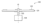
- FIG. 2A shows a planar configuration of the phosphor wheel 120
- FIG. 2B shows a cross-sectional configuration of the phosphor wheel 120 taken along the line II shown in FIG. 2A
- the phosphor wheel 120 includes, for example, a disk-shaped base portion 121, and a phosphor layer 122 is provided on the base portion 121.
- a motor 124 is connected to the base part 121 via a shaft 123, and the motor 124 enables the base part 121 to rotate in the direction of arrow C about a rotation axis O passing through the center of the base part 121. ing.
- the phosphor wheel 120 and the condensing lenses 124A and 124B constituting the light conversion unit 12 and the cooling fan 130 constituting the cooling unit 13 are as shown in FIGS. 3A and 3B, respectively. It is preferable to be housed in the housing 125 (first internal housing) and the housing 132 (second internal housing). Each of the housing 125 and the housing 132 has a substantially rectangular parallelepiped shape, and is connected so that the longitudinal direction 12 of the housing 125 and the longitudinal direction 11 of the housing 132 are orthogonal to each other.
- planar direction (longitudinal direction l2) of the base body part 121 of the phosphor wheel 120 constituting the light conversion part 12 and the longitudinal direction l1 of the cooling fan 130 constituting the cooling part 13 are substantially perpendicular to each other. Is arranged.
- the housing 125 that accommodates the phosphor wheel 120 and the condensing lenses 124A and 124B has an opening 125A and an opening 125B that are connected to the housing 132 on one of its side surfaces.
- the housing 132 has two spaces 133 and 134 partitioned by a partition wall 132A, and the cooling fan 130 is accommodated in the space 133.
- the space 134 is provided with two openings (a blowing port 134A and a suction port 134B) connected to the housing 125, and the air heated at the light emitting point X on the phosphor wheel 120 through the suction port 134B. This is a ventilation path for sending (warm air) to the intake port 131 of the cooling fan 130.
- the longitudinal direction 11 of the housing 132 in which the cooling unit 13 is accommodated extends from the light conversion unit 12 toward the intake port 51.
- the housing 132 is preferably arranged in the vicinity of the side surface S3 of the housing 50.
- the housing 125 has openings (not shown) through which light emitted from the light source unit 11 passes through the surfaces of the phosphor wheel 120 facing the light emission point X on the light source unit 11 side and the illumination optical system 21 side, respectively. ),
- a condensing lens or the like is fitted in the opening.
- the light source unit 11 includes, for example, a light source 111 having a plurality of LDs, and condensing mirrors 112A and 112B and a condensing mirror 113 as an optical system for condensing the light emitted from the light source 111 on the phosphor wheel 120. And have. Although not shown in FIG. 4, for example, a blue light source that emits blue laser light Lb that is combined with light (yellow light Ly) emitted from the light conversion unit 12 to generate white light (Lw) Have
- the light source 111 is, for example, a blue LD that can oscillate blue laser light Lb having a peak wavelength of emission intensity within a wavelength range of 400 nm to 500 nm.
- a blue LD that can oscillate blue laser light Lb having a peak wavelength of emission intensity within a wavelength range of 400 nm to 500 nm.
- other light sources such as LEDs may be used as the light source 111.
- the wavelength range is not limited to the blue laser light Lb having the peak wavelength of the emission intensity at 400 nm to 500 nm.
- the light conversion unit 12 includes the phosphor wheel 120 and the condensing lenses 124A and 124B that collect the light incident from the light source unit 11 at a predetermined position of the phosphor wheel 120 as described above.
- the phosphor wheel 120 and the condensing lenses 124A and 124B are accommodated in a housing 125, for example.
- Light (parallel light) incident on the integrator element 214 from the light source optical system 10 is divided into a plurality of light beams by the microlens of the first fly-eye lens 212, and is respectively applied to the corresponding microlens in the second fly-eye lens 213. Imaged.
- Each of the micro lenses of the second fly-eye lens 213 functions as a secondary light source, and irradiates the polarization conversion element 215 with incident light as a plurality of parallel lights with uniform brightness.
- the integrator element 214 as a whole has a function of adjusting incident light irradiated from the light source optical system 10 to the polarization conversion element 215 into a uniform luminance distribution.
- the polarization conversion element 215 has a function of aligning the polarization state of incident light incident through the integrator element 214 or the like.
- the polarization conversion element 215 emits outgoing light including blue light B, green light G, and red light R via, for example, a condenser lens 216 disposed on the outgoing side of the light source optical system 10.
- the lens 312 is a symmetric optical system disposed on the same central axis S, and is accommodated in the lens barrel 313, for example.
- the lens 312 is a lens for projecting (enlarged projection) illumination light (video light) modulated by the image generating element 23 onto the wall surface WS.
- the lens 312 forms an intermediate image M in front of the concave mirror 311.
- the intermediate image M may be formed before the concave mirror 311 or between the lens 312 and the concave mirror 311 or inside the lens 312.
- the light source unit 11 and the light conversion unit 12 are arranged on the linear flow path F formed in the housing 50. Further, a cooling unit 13 for cooling the light conversion unit 12 is arranged at a position shifted from the flow path F. Thereby, the pressure loss of the cooling unit 13 is reduced, and the exhaust heat of the light conversion unit 12 is efficiently performed by the air taken in from the intake port 51. Therefore, it is possible to improve the cooling efficiency.
- FIG. 6 schematically illustrates the appearance of the cooling unit 73 constituting the projection display device (projector 1) according to Modification 1 of the present disclosure.
- the cooling fan 730 is accommodated in the housing 132 as in the above embodiment.
- the housing 132 shows only the space 133 in FIG. 3A, for example.
- the cooling unit 73 according to the present modification is provided with a plurality of fins 736 and 737 at positions outside the housing 132 and corresponding to the duct 730 ⁇ / b> D in front of the air blowing port 735. This point is different from the cooling fan 130 in the above embodiment.
- the image generation system 20 configured using a transmissive liquid crystal panel is described, but an image generation system using a reflective liquid crystal panel may be used.
- a digital micromirror device (DMD) or the like may be used as the image generation element.
- a polarization beam splitter (PBS) instead of the dichroic prism 232, a polarization beam splitter (PBS), a color synthesis prism that synthesizes RGB video signals, a TIR (Total Internal Reflection) prism, or the like may be used.
- PBS polarization beam splitter
- TIR Total Internal Reflection
- a device other than the projector may be configured as the projection display device according to the present technology.
- the light conversion unit has a longitudinal direction in plan view, The projection display device according to (1) or (2), wherein the longitudinal direction of the light conversion unit is orthogonal to the air flow path.
- the light conversion unit has a longitudinal direction in plan view, The projection display device according to (2) or (3), wherein the light conversion unit and the cooling unit are arranged so that the longitudinal directions thereof are substantially perpendicular to each other.
- the cooling unit is connected to the light conversion unit, The projection display device according to any one of (2) to (4), wherein the longitudinal direction of the cooling unit extends from the light conversion unit toward the intake port.
Abstract
According to one embodiment of the present invention, a projection display device is provided with: a light source optical system, which has a light source unit, a light conversion unit that converts outputted light from the light source unit into light of a wavelength region different from that of the outputted light, and a cooling unit that cools the light conversion unit; and an external housing, which houses the light source optical system, and has a suction port and an exhaust port, with which a linear air flow passage is formed. The light source unit and the light conversion unit are disposed on the air flow passage, and the cooling unit is disposed at a position shifted from the air flow passage.
Description
本開示は、光変換部およびその冷却部を備えた投射型表示装置に関する。
The present disclosure relates to a projection display device including a light conversion unit and a cooling unit thereof.
壁際やテーブル等に置いて映像を投射する短焦点プロジェクタでは、その商品外形は、横長の直方体状になる場合が多い。また、製品内部の部品レイアウトとしては、中央部に投射レンズを配置する場合が多い。このような短焦点プロジェクタにおいて、製品内部の空間の利用効率を向上させるためには、例えば、特許文献1における前面投射型液晶表示装置のように、光源ランプ部から投射レンズ部までの光学ユニットをUの字状に配置することが有効である。
In short focus projectors that project images on the wall or on a table, the product outline is often a horizontally long rectangular parallelepiped. Moreover, as a component layout inside a product, a projection lens is often arranged at the center. In such a short focus projector, in order to improve the utilization efficiency of the space inside the product, for example, an optical unit from the light source lamp unit to the projection lens unit as in the front projection type liquid crystal display device in Patent Document 1 is used. It is effective to arrange in a U-shape.
上記のような構成を有する短焦点プロジェクタでは、光学ユニット中の発熱量は、光源に近いほど大きく、投射レンズに近づくほど小さい。このため、光源には、光源用の冷却ファン等が設置されている。
In the short focus projector having the above-described configuration, the amount of heat generated in the optical unit is larger as it is closer to the light source and is smaller as it is closer to the projection lens. For this reason, a cooling fan or the like for the light source is installed in the light source.
ところで、短焦点プロジェクタでは、光源とは別に、光源から出射される光を異なる波長に変換する光変換部を備えたものがある。このような短焦点プロジェクタでは、レーザダイオード(Laser Diode;LD)等の光源からの光を蛍光体に照射することにより、蛍光としての白色光を取り出しており、光学ユニットは、例えば、蛍光体を励起させる励起光を出射させる励起用光源(光源部)と、励起光を受けて励起光とは異なる波長光を発する蛍光体層を有する蛍光体ホイール(光変換部)とを備えている。このような光学ユニットでは、例えば、光源部の次に光変換部からの発熱量が多い。このため、蛍光体ホイール近傍を含めた冷却効率の向上が求められている。
Incidentally, some short focus projectors include a light conversion unit that converts light emitted from a light source into a different wavelength, in addition to the light source. In such a short-focus projector, white light as fluorescence is extracted by irradiating light from a light source such as a laser diode (LD) to the phosphor. An excitation light source (light source unit) that emits excitation light to be excited and a phosphor wheel (light conversion unit) having a phosphor layer that receives the excitation light and emits light having a wavelength different from that of the excitation light are provided. In such an optical unit, for example, the amount of heat generated from the light conversion unit is large next to the light source unit. For this reason, the improvement of the cooling efficiency including the phosphor wheel vicinity is calculated | required.
冷却効率を向上させることが可能な投射型表示装置を提供することが望ましい。
It is desirable to provide a projection display device capable of improving the cooling efficiency.
本開示の一実施形態の投射型表示装置は、光源部、光源部からの出射光を、出射光の波長域とは異なる波長域の光に変換する光変換部および光変換部を冷却する冷却部を有する光源光学系と、光源光学系を収容すると共に、直線状の空気流路を形成する吸気口および排気口を有する外部筐体とを備えたものであり、光源部および光変換部は、空気流路上に配置され、冷却部は、空気流路上からシフトした位置に配置されている。
A projection display device according to an embodiment of the present disclosure includes a light source unit, a light conversion unit that converts light emitted from the light source unit into light having a wavelength region different from the wavelength region of the emitted light, and cooling that cools the light conversion unit. A light source optical system having a portion, and an external housing that houses the light source optical system and has an intake port and an exhaust port that form a linear air flow path. The cooling unit is arranged at a position shifted from the air channel.
本開示の一実施形態の投射型表示装置では、外部筐体に設けられた吸気口および排気口によって形成される直線状の空気流路上に光源部および光変換部を配置し、光変換部を冷却する冷却部を空気流路からシフトした位置に配置するようにした。これにより、冷却部の圧力損失を低減することが可能となる。また、吸気口から取り入れられた空気によって効率よく光変換部の排熱を行うことが可能となる。
In the projection display device according to an embodiment of the present disclosure, the light source unit and the light conversion unit are arranged on a linear air flow path formed by the air inlet and the air outlet provided in the external housing, and the light conversion unit is arranged. The cooling part to be cooled is arranged at a position shifted from the air flow path. Thereby, it becomes possible to reduce the pressure loss of a cooling part. In addition, it is possible to efficiently exhaust heat from the light conversion unit by the air taken in from the intake port.
本開示の一実施形態の投射型表示装置によれば、直線状の空気流路上に光源部および光変換部を配置し、空気流路からシフトした位置に光変換部を冷却する冷却部を配置するようにしたので、冷却部の圧力損失が低減される。また、吸気口から取り入れられた空気による効率のよい光変換部の排熱が可能となる。よって、冷却効率を向上させることが可能となる。
According to the projection display device of an embodiment of the present disclosure, the light source unit and the light conversion unit are disposed on the linear air flow path, and the cooling unit that cools the light conversion unit is disposed at a position shifted from the air flow path. As a result, the pressure loss in the cooling section is reduced. In addition, it is possible to efficiently exhaust heat from the light conversion unit by the air taken in from the intake port. Therefore, it is possible to improve the cooling efficiency.
なお、ここに記載された効果は必ずしも限定されるものではなく、本開示中に記載されたいずれの効果であってもよい。
In addition, the effect described here is not necessarily limited, and may be any effect described in the present disclosure.
以下、本開示の実施の形態について、図面を参照して詳細に説明する。なお、説明は以下の順序で行う。
1.実施の形態(空気流路からシフトした位置に蛍光体ホイール用の冷却ファンを配置した例)
1-1.要部の構成
1-2.投射型表示装置の構成
1-3.作用・効果
2.変形例
2-1.変形例1(冷却ファンにフィンを設けた例)
2-2.変形例2(冷却ファンの一部が筐体から露出した例) Hereinafter, embodiments of the present disclosure will be described in detail with reference to the drawings. The description will be given in the following order.
1. Embodiment (example in which a cooling fan for a phosphor wheel is arranged at a position shifted from an air flow path)
1-1. Configuration of main part 1-2. Configuration of Projection Display 1-3 Action / Effect Modification 2-1. Modification 1 (example in which fins are provided on the cooling fan)
2-2. Modification 2 (example in which a part of the cooling fan is exposed from the housing)
<1.実施の形態>
図1は、本開示の一実施の形態に係る投射型表示装置(プロジェクタ1)の全体構成を表したものである。このプロジェクタ1は、壁面等のスクリーン2(被投射面)に対して映像(映像光)を投影する投射型の表示装置であり、光源光学系10と、画像生成システム20と、投射光学系30と、電源ユニット40と、これらを収容する筐体50とを有する。光源光学系10は、例えば、光源部11と、光変換部12と、光変換部12を冷却する冷却部13とを含んで構成されている。 <1. Embodiment>
FIG. 1 illustrates an overall configuration of a projection display device (projector 1) according to an embodiment of the present disclosure. Theprojector 1 is a projection-type display device that projects an image (video light) onto a screen 2 (projected surface) such as a wall surface, and includes a light source optical system 10, an image generation system 20, and a projection optical system 30. And a power supply unit 40 and a housing 50 for housing them. The light source optical system 10 includes, for example, a light source unit 11, a light conversion unit 12, and a cooling unit 13 that cools the light conversion unit 12.
図1は、本開示の一実施の形態に係る投射型表示装置(プロジェクタ1)の全体構成を表したものである。このプロジェクタ1は、壁面等のスクリーン2(被投射面)に対して映像(映像光)を投影する投射型の表示装置であり、光源光学系10と、画像生成システム20と、投射光学系30と、電源ユニット40と、これらを収容する筐体50とを有する。光源光学系10は、例えば、光源部11と、光変換部12と、光変換部12を冷却する冷却部13とを含んで構成されている。 <1. Embodiment>
FIG. 1 illustrates an overall configuration of a projection display device (projector 1) according to an embodiment of the present disclosure. The
(1-1.要部の構成)
本実施の形態のプロジェクタ1では、筐体50には、筐体50の内部を冷却するための空気を吸い込む吸気口51と、筐体50内部の空気を排出する排気口52とが設けられている。吸気口51は、スクリーン2と正対する面(背面S1、リア側)に、排気口52は、背面S1と対向する面(前面S2、フロント側)に設けられており、互いに対向するように配設されている。これにより、筐体50の内部には、X軸方向(背面S1から前面S2)に向かって直進する空気の流れ(流路F(空気流路))が形成される。 (1-1. Configuration of main parts)
Inprojector 1 according to the present embodiment, housing 50 is provided with an intake port 51 for sucking air for cooling the inside of housing 50 and an exhaust port 52 for discharging the air inside housing 50. Yes. The intake port 51 is provided on a surface (back surface S1, rear side) facing the screen 2 and the exhaust port 52 is provided on a surface (front surface S2, front side) facing the back surface S1, and is arranged to face each other. It is installed. As a result, an air flow (flow path F (air flow path)) that travels straight in the X-axis direction (from the back surface S1 to the front surface S2) is formed inside the housing 50.
本実施の形態のプロジェクタ1では、筐体50には、筐体50の内部を冷却するための空気を吸い込む吸気口51と、筐体50内部の空気を排出する排気口52とが設けられている。吸気口51は、スクリーン2と正対する面(背面S1、リア側)に、排気口52は、背面S1と対向する面(前面S2、フロント側)に設けられており、互いに対向するように配設されている。これにより、筐体50の内部には、X軸方向(背面S1から前面S2)に向かって直進する空気の流れ(流路F(空気流路))が形成される。 (1-1. Configuration of main parts)
In
プロジェクタ1では、光源光学系10、画像生成システム20および投射光学系30は、Uの字状に配置されている。即ち、光源光学系10の光源部11と、投射光学系30とが近接するように配置されている。また、投射光学系30から投射される画像IMGは、光源光学系10を構成する光源部11から出射される光と略同一方向を有する。
In the projector 1, the light source optical system 10, the image generation system 20, and the projection optical system 30 are arranged in a U-shape. That is, the light source unit 11 of the light source optical system 10 and the projection optical system 30 are disposed so as to be close to each other. Further, the image IMG projected from the projection optical system 30 has substantially the same direction as the light emitted from the light source unit 11 constituting the light source optical system 10.
光源光学系10を構成する光源部11および光変換部12は、対向配置された吸気口51と排気口52との間に、吸気口51側から、光変換部12および光源部11の順に配置されている。光変換部12を冷却する冷却部13は、流路Fからシフトした位置に配置されている。具体的には、冷却部13は、流路F上の光変換部12を基準に、投射光学系30とは反対側にシフトして配置されている。即ち、筐体50の側面S3に近接して設置され配置されている。また、冷却部13は、平面視的に長手方向l1を有し、この長手方向l1が、流路Fと略平行になるように配置されている。
The light source unit 11 and the light conversion unit 12 constituting the light source optical system 10 are arranged in the order of the light conversion unit 12 and the light source unit 11 from the intake port 51 side between the opposed intake port 51 and the exhaust port 52. Has been. The cooling unit 13 that cools the light conversion unit 12 is arranged at a position shifted from the flow path F. Specifically, the cooling unit 13 is shifted to the opposite side of the projection optical system 30 with respect to the light conversion unit 12 on the flow path F. That is, it is installed and arranged in the vicinity of the side surface S3 of the housing 50. The cooling unit 13 has a longitudinal direction 11 in plan view, and the longitudinal direction 11 is disposed so as to be substantially parallel to the flow path F.
以下に、光変換部12および冷却部13の構成について、詳細に説明する。
Hereinafter, the configuration of the light conversion unit 12 and the cooling unit 13 will be described in detail.
光変換部12は、例えば、光源部11から出射された光を異なる波長域の光に変換する蛍光体ホイール120と、光源部11から出射された光を蛍光体ホイール120の所定の位置(発光点X)に集光させる集光レンズ124A,124Bとを有する(図2A,図2Bおよび図4参照)。
The light conversion unit 12, for example, converts the light emitted from the light source unit 11 into light having a different wavelength range, and the light emitted from the light source unit 11 at a predetermined position (light emission) of the phosphor wheel 120. Condensing lenses 124A and 124B that collect light at point X) (see FIGS. 2A, 2B, and 4).
図2Aは、蛍光体ホイール120の平面構成を表したものであり、図2Bは、図2Aに示したI-I線における蛍光体ホイール120の断面構成を表したものである。蛍光体ホイール120は、例えば円盤形状の基体部121を有し、この基体部121上に蛍光体層122が設けられている。基体部121には、シャフト123を介してモータ124が接続されており、このモータ124によって、基体部121は、基体部121の中心を通る回転軸Oを中心に矢印C方向に回転可能となっている。
FIG. 2A shows a planar configuration of the phosphor wheel 120, and FIG. 2B shows a cross-sectional configuration of the phosphor wheel 120 taken along the line II shown in FIG. 2A. The phosphor wheel 120 includes, for example, a disk-shaped base portion 121, and a phosphor layer 122 is provided on the base portion 121. A motor 124 is connected to the base part 121 via a shaft 123, and the motor 124 enables the base part 121 to rotate in the direction of arrow C about a rotation axis O passing through the center of the base part 121. ing.
蛍光体層122は、光源部11から照射される光によって励起されて、その光の波長域とは異なる波長域を有する蛍光を発するものである。本実施の形態では、蛍光体層122は、約445nmの中心波長を持つ青色光Lb(青色レーザ光)によって励起されて蛍光を発する蛍光物質を含んでおり、光源部11から照射される青色レーザ光Lbを、例えば黄色光Lyに変換して基体部121の背面側(照明光学系21側)に出射する。
The phosphor layer 122 is excited by light emitted from the light source unit 11 and emits fluorescence having a wavelength range different from the wavelength range of the light. In the present embodiment, the phosphor layer 122 includes a fluorescent material that emits fluorescence when excited by the blue light Lb (blue laser light) having a center wavelength of about 445 nm, and is emitted from the light source unit 11. The light Lb is converted into, for example, yellow light Ly, and emitted to the back side (illumination optical system 21 side) of the base portion 121.
蛍光体層122に含まれる蛍光物質としては、例えば、YAG(イットリウム・アルミニウム・ガーネット)系蛍光体が用いられる。なお、蛍光物質の種類、励起される光の波長域、および励起により発生される可視光の波長域は限定されない。
As the fluorescent substance contained in the phosphor layer 122, for example, a YAG (yttrium, aluminum, garnet) phosphor is used. In addition, the kind of fluorescent substance, the wavelength range of the excited light, and the wavelength range of the visible light generated by excitation are not limited.
蛍光体層122から出射された黄色光Lyは、基体部121を透過して照明光学系21(具体的には、折り返しミラー211)に出射される。
The yellow light Ly emitted from the phosphor layer 122 passes through the base portion 121 and is emitted to the illumination optical system 21 (specifically, the folding mirror 211).
冷却部13は、光変換部12、具体的には、蛍光体ホイール120の発光点Xを冷却する冷却ファン130を有する。冷却ファン130としては、例えば、回転軸に対して直交方向に風が出るシロッコファンを用いることが好ましい。
The cooling unit 13 includes a cooling fan 130 that cools the light conversion unit 12, specifically, the light emission point X of the phosphor wheel 120. As the cooling fan 130, for example, it is preferable to use a sirocco fan that emits wind in a direction orthogonal to the rotation axis.
本実施の形態では、光変換部12を構成する蛍光体ホイール120および集光レンズ124A,124Bと、冷却部13を構成する冷却ファン130は、それぞれ、図3Aおよび図3Bに示したように、筐体125(第1の内部筐体)および筐体132(第2の内部筐体)に収容されていることが好ましい。筐体125および筐体132とは、それぞれ、略直方体形状を有し、それぞれ、筐体125の長手方向l2と、筐体132の長手方向l1とが互いに直交するように接続されている。換言すると、光変換部12を構成する蛍光体ホイール120の基体部121の平面方向(長手方向l2)と、冷却部13を構成する冷却ファン130の長手方向l1とは、互いに略直角になるように配置されている。
In the present embodiment, the phosphor wheel 120 and the condensing lenses 124A and 124B constituting the light conversion unit 12 and the cooling fan 130 constituting the cooling unit 13 are as shown in FIGS. 3A and 3B, respectively. It is preferable to be housed in the housing 125 (first internal housing) and the housing 132 (second internal housing). Each of the housing 125 and the housing 132 has a substantially rectangular parallelepiped shape, and is connected so that the longitudinal direction 12 of the housing 125 and the longitudinal direction 11 of the housing 132 are orthogonal to each other. In other words, the planar direction (longitudinal direction l2) of the base body part 121 of the phosphor wheel 120 constituting the light conversion part 12 and the longitudinal direction l1 of the cooling fan 130 constituting the cooling part 13 are substantially perpendicular to each other. Is arranged.
蛍光体ホイール120および集光レンズ124A,124Bを収容する筐体125は、その側面の1つに、筐体132と接続される開口125Aおよび開口125Bを有する。筐体132は、隔壁132Aによって仕切られた2つの空間133,134を有し、空間133には、冷却ファン130が収容されている。空間134には、筐体125と接続される2つの開口(吹き出し口134Aおよび吸い込み口134B)が設けられており、吸い込み口134Bを介して蛍光体ホイール120上の発光点Xにおいて暖められた空気(暖風)を冷却ファン130の吸気口131に送るための送風路となっている。
The housing 125 that accommodates the phosphor wheel 120 and the condensing lenses 124A and 124B has an opening 125A and an opening 125B that are connected to the housing 132 on one of its side surfaces. The housing 132 has two spaces 133 and 134 partitioned by a partition wall 132A, and the cooling fan 130 is accommodated in the space 133. The space 134 is provided with two openings (a blowing port 134A and a suction port 134B) connected to the housing 125, and the air heated at the light emitting point X on the phosphor wheel 120 through the suction port 134B. This is a ventilation path for sending (warm air) to the intake port 131 of the cooling fan 130.
即ち、本実施の形態では、筐体125の開口125Aは、筐体132の吹き出し口134Aと接合され、筐体125の開口125Bは、筐体132の吸い込み口134Bと接合されている。これにより、光変換部12および冷却部13は、密閉空間に収容されている。即ち、光変換部12の冷却は、密閉循環冷却となっている。
That is, in this embodiment, the opening 125A of the housing 125 is joined to the outlet 134A of the housing 132, and the opening 125B of the housing 125 is joined to the suction port 134B of the housing 132. Thereby, the light conversion part 12 and the cooling part 13 are accommodated in sealed space. That is, the cooling of the light conversion unit 12 is hermetic circulation cooling.
この密閉空間における空気の流れは、以下の通りである。冷却部13では、冷却ファン130の送風口135から送風された空気(冷風)は、図3Aおよび図3Bに示したように、筐体132の吹き出し口134Aおよびこれに接続された開口125Aを通って筐体125内に送られ、蛍光体ホイール120上の発光点を冷却する。蛍光体ホイール120上の発光点Xにおいて暖められた空気(暖風)は、筐体125の開口125Bおよびこれに接続された吸い込み口134Bを通って冷却ファン130の吸気口131に吸い込まれる。
The air flow in this sealed space is as follows. In the cooling unit 13, the air (cold air) blown from the air blowing port 135 of the cooling fan 130 passes through the air outlet 134A of the housing 132 and the opening 125A connected thereto, as shown in FIGS. 3A and 3B. Are sent into the housing 125 to cool the light emitting points on the phosphor wheel 120. Air (warm air) warmed at the light emitting point X on the phosphor wheel 120 is sucked into the air inlet 131 of the cooling fan 130 through the opening 125B of the housing 125 and the air inlet 134B connected thereto.
なお、筐体132の吹き出し口134Aおよびこれに接続される筐体125の開口125Aは、蛍光体ホイール120の発光点Xの近傍に位置するように形成することが好ましい。これにより、発光点Xの冷却効率が向上する。また、筐体125の開口125Bおよびこれに接続される筐体132の吸い込み口134Bは、蛍光体ホイール120の発光点Xを基準にして、蛍光体ホイール120の回転方向の下流側、例えば、蛍光体ホイール120が図3Aに示した矢印C方向に回転する場合には、筐体132の吹き出し口134Aおよび筐体125の開口125Aの上側に形成することが好ましい。これにより、筐体125内の排熱効率が向上する。
Note that it is preferable to form the outlet 134A of the casing 132 and the opening 125A of the casing 125 connected thereto so as to be positioned in the vicinity of the light emission point X of the phosphor wheel 120. Thereby, the cooling efficiency of the light emitting point X is improved. Further, the opening 125B of the casing 125 and the suction port 134B of the casing 132 connected to the opening 125B are on the downstream side in the rotation direction of the phosphor wheel 120 with respect to the emission point X of the phosphor wheel 120, for example, fluorescent When the body wheel 120 rotates in the direction of arrow C shown in FIG. 3A, it is preferable that the body wheel 120 is formed above the outlet 134 </ b> A of the housing 132 and the opening 125 </ b> A of the housing 125. Thereby, the exhaust heat efficiency in the housing | casing 125 improves.
また、冷却部13が収容される筐体132は、長手方向l1が、光変換部12から吸気口51に向かって延在していることが好ましい。換言すると、筐体132は、筐体50の側面S3近傍に配置することが好ましい。これにより、筐体50内のスペースを有効に利用することができ、プロジェクタ1を小型化することが可能となる。
In addition, it is preferable that the longitudinal direction 11 of the housing 132 in which the cooling unit 13 is accommodated extends from the light conversion unit 12 toward the intake port 51. In other words, the housing 132 is preferably arranged in the vicinity of the side surface S3 of the housing 50. Thereby, the space in the housing | casing 50 can be utilized effectively and the projector 1 can be reduced in size.
更に、光変換部12が収容される筐体125は、対向配置された吸気口51と排気口52との間、即ち、流路F上に、筐体125の長手方向l2が流路Fと直交するように配置することが好ましく、筐体132は、その長手方向l1が、筐体50の側面S3および流路Fと略平行になるように配置することが好ましい。これにより、吸気口51から吸い込まれた空気が、冷却部13によって妨げられることなく、光変換部12を冷却すること可能となり、冷却効率が向上する。
Further, the housing 125 in which the light conversion unit 12 is accommodated is located between the air inlet 51 and the air outlet 52 arranged opposite to each other, that is, on the flow path F, and the longitudinal direction 12 of the housing 125 is the flow path F. The casing 132 is preferably arranged so as to be orthogonal to each other, and the casing 132 is preferably arranged so that its longitudinal direction 11 is substantially parallel to the side surface S3 of the casing 50 and the flow path F. Thereby, it becomes possible to cool the light conversion part 12 without the air suck | inhaled from the inlet 51 being interrupted by the cooling part 13, and a cooling efficiency improves.
なお、筐体125には、蛍光体ホイール120の発光点Xと正対する光源部11側および照明光学系21側の面に、それぞれ光源部11から出射された光が通過する開口(図示せず)が設けられているが、この開口には、例えば、集光レンズ等がはめ込まれている。
Note that the housing 125 has openings (not shown) through which light emitted from the light source unit 11 passes through the surfaces of the phosphor wheel 120 facing the light emission point X on the light source unit 11 side and the illumination optical system 21 side, respectively. ), For example, a condensing lens or the like is fitted in the opening.
(1-2.投射型表示装置の構成)
図4は、プロジェクタ1を構成する各光学系の構成の一例を表す概略図である。本実施の形態のプロジェクタ1は、上記のように、光源光学系10と、画像生成システム20と、投射光学系30とを有する。画像生成システム20は、照射された光を元に画像を生成する画像生成素子23と、画像生成素子23に光源光学系10から出射された光を照射する照明光学系21とを有する。投射光学系30は、画像生成素子23により生成された画像を投射する。 (1-2. Configuration of Projection Display Device)
FIG. 4 is a schematic diagram illustrating an example of the configuration of each optical system constituting theprojector 1. The projector 1 according to the present embodiment includes the light source optical system 10, the image generation system 20, and the projection optical system 30 as described above. The image generation system 20 includes an image generation element 23 that generates an image based on irradiated light, and an illumination optical system 21 that irradiates the image generation element 23 with light emitted from the light source optical system 10. The projection optical system 30 projects an image generated by the image generation element 23.
図4は、プロジェクタ1を構成する各光学系の構成の一例を表す概略図である。本実施の形態のプロジェクタ1は、上記のように、光源光学系10と、画像生成システム20と、投射光学系30とを有する。画像生成システム20は、照射された光を元に画像を生成する画像生成素子23と、画像生成素子23に光源光学系10から出射された光を照射する照明光学系21とを有する。投射光学系30は、画像生成素子23により生成された画像を投射する。 (1-2. Configuration of Projection Display Device)
FIG. 4 is a schematic diagram illustrating an example of the configuration of each optical system constituting the
光源部11は、例えば、複数のLDを備えた光源111と、光源111から出射された光を蛍光体ホイール120に集光させるための光学系としての集光ミラー112A,112Bおよび集光ミラー113とを有する。また、図4では図示していないが、例えば、光変換部12から出射された光(黄色光Ly)と合成して白色光(Lw)とするための青色レーザ光Lbを出射する青色光源等を有する。
The light source unit 11 includes, for example, a light source 111 having a plurality of LDs, and condensing mirrors 112A and 112B and a condensing mirror 113 as an optical system for condensing the light emitted from the light source 111 on the phosphor wheel 120. And have. Although not shown in FIG. 4, for example, a blue light source that emits blue laser light Lb that is combined with light (yellow light Ly) emitted from the light conversion unit 12 to generate white light (Lw) Have
光源111は、例えば、400nm~500nmの波長範囲内に発光強度のピーク波長を有する青色レーザ光Lbを発振可能な青色LDである。光源111には、LDのほか、LED等の他の光源が用いられていてもよい。また、波長範囲も、上記400nm~500nmに発光強度のピーク波長を有する青色レーザ光Lbに限定されるものではない。
The light source 111 is, for example, a blue LD that can oscillate blue laser light Lb having a peak wavelength of emission intensity within a wavelength range of 400 nm to 500 nm. In addition to the LD, other light sources such as LEDs may be used as the light source 111. Further, the wavelength range is not limited to the blue laser light Lb having the peak wavelength of the emission intensity at 400 nm to 500 nm.
集光ミラー112A,112Bは、光源111に配置された複数のLDから出射される光の光束を略平行にすると共に、集光ミラー113に集中させる凹面反射面を有するものである。集光ミラー113は、集光ミラー112A,112Bによって集中した光を蛍光体ホイール120へ反射するためのものである。
The condensing mirrors 112 </ b> A and 112 </ b> B have concave reflection surfaces that make light beams emitted from a plurality of LDs arranged in the light source 111 substantially parallel and concentrate on the condensing mirror 113. The condensing mirror 113 is for reflecting the light concentrated by the condensing mirrors 112 </ b> A and 112 </ b> B to the phosphor wheel 120.
なお、光源部11は、筐体(図示せず)に収容されており、この光源部11が収容されている筐体には、例えば蛍光体ホイール120等が収容された筐体125が接続されている。
The light source unit 11 is housed in a housing (not shown), and a housing 125 housing, for example, a phosphor wheel 120 is connected to the housing in which the light source unit 11 is housed. ing.
光変換部12は、上記のように、蛍光体ホイール120と、光源部11から入射した光を蛍光体ホイール120の所定の位置に集光させる集光レンズ124A,124Bを有する。これら蛍光体ホイール120および集光レンズ124A,124Bは、例えば、筐体125に収容されている。
The light conversion unit 12 includes the phosphor wheel 120 and the condensing lenses 124A and 124B that collect the light incident from the light source unit 11 at a predetermined position of the phosphor wheel 120 as described above. The phosphor wheel 120 and the condensing lenses 124A and 124B are accommodated in a housing 125, for example.
光源部11から入射された光は、集光レンズ124A,124Bによって、蛍光体ホイール120上の蛍光体層122の所定の位置(発光点X)に照射される。蛍光体層122は、光源部11から照射される光によって励起されて、その光(例えば、青色レーザ光Lb)の波長域とは異なる波長域を有する蛍光(例えば黄色光Ly)を発する。即ち、蛍光体層122は、光源部11から照射される青色レーザ光Lbを、黄色光Lyに変換して照明光学系21側に出射する。なお、この黄色光Lyは、上述した青色光源から出射された青色レーザ光Lbと合成されて白色光(Lw)として、照明光学系21側に出射される。
The light incident from the light source unit 11 is irradiated to a predetermined position (light emission point X) of the phosphor layer 122 on the phosphor wheel 120 by the condenser lenses 124A and 124B. The phosphor layer 122 is excited by light emitted from the light source unit 11 and emits fluorescence (for example, yellow light Ly) having a wavelength range different from that of the light (for example, blue laser light Lb). That is, the phosphor layer 122 converts the blue laser light Lb emitted from the light source unit 11 into yellow light Ly and emits it to the illumination optical system 21 side. The yellow light Ly is combined with the blue laser light Lb emitted from the above-described blue light source and emitted as white light (Lw) to the illumination optical system 21 side.
照明光学系21は、図4に示したように、例えば、折り返しミラー211と、インテグレータ素子214と、偏光変換素子215と、集光レンズ216とを有する。インテグレータ素子214は、二次元に配列された複数のマイクロレンズを有する第1のフライアイレンズ212およびその各マイクロレンズに1つずつ対応するように配列された複数のマイクロレンズを有する第2のフライアイレンズ213を含んでいる。
The illumination optical system 21 includes, for example, a folding mirror 211, an integrator element 214, a polarization conversion element 215, and a condenser lens 216, as shown in FIG. The integrator element 214 includes a first fly-eye lens 212 having a plurality of microlenses arranged two-dimensionally, and a second flyeye having a plurality of microlenses arranged to correspond to each of the microlenses. An eye lens 213 is included.
光源光学系10からインテグレータ素子214に入射する光(平行光)は、第1のフライアイレンズ212のマイクロレンズによって複数の光束に分割され、第2のフライアイレンズ213における対応するマイクロレンズにそれぞれ結像される。第2のフライアイレンズ213のマイクロレンズのそれぞれが、二次光源として機能し、輝度が揃った複数の平行光を、偏光変換素子215に入射光として照射する。
Light (parallel light) incident on the integrator element 214 from the light source optical system 10 is divided into a plurality of light beams by the microlens of the first fly-eye lens 212, and is respectively applied to the corresponding microlens in the second fly-eye lens 213. Imaged. Each of the micro lenses of the second fly-eye lens 213 functions as a secondary light source, and irradiates the polarization conversion element 215 with incident light as a plurality of parallel lights with uniform brightness.
インテグレータ素子214は、全体として、光源光学系10から偏光変換素子215に照射される入射光を、均一な輝度分布に整える機能を有する。
The integrator element 214 as a whole has a function of adjusting incident light irradiated from the light source optical system 10 to the polarization conversion element 215 into a uniform luminance distribution.
偏光変換素子215は、インテグレータ素子214等を介して入射する入射光の偏光状態を揃える機能を有する。この偏光変換素子215は、例えば、光源光学系10の出射側に配置された集光レンズ216等を介して、青色光B、緑色光Gおよび赤色光Rを含む出射光を出射する。
The polarization conversion element 215 has a function of aligning the polarization state of incident light incident through the integrator element 214 or the like. The polarization conversion element 215 emits outgoing light including blue light B, green light G, and red light R via, for example, a condenser lens 216 disposed on the outgoing side of the light source optical system 10.
照明光学系21は、ダイクロイックミラー217,218、ミラー219,220,221、リレーレンズ223,224、フィールドレンズ222R,222G,222B、画像生成素子としての液晶ライトバルブ231R,231G,231B、ダイクロイックプリズム232を含んでいる。
The illumination optical system 21 includes dichroic mirrors 217 and 218, mirrors 219, 220, and 221, relay lenses 223 and 224, field lenses 222R, 222G, and 222B, liquid crystal light valves 231R, 231G, and 231B as image generation elements, and a dichroic prism 232 Is included.
ダイクロイックミラー217,218は、所定の波長域の色光を選択的に反射し、それ以外の波長域の光を透過させる性質を有する。図4を参照して、例えば、ダイクロイックミラー217は、赤色光R(Lr)を選択的に反射する。ダイクロイックミラー218は、ダイクロイックミラー217を透過した緑色光Gおよび青色光Bうち、緑色光G(Lg)を選択的に反射する。残る青色光B(Lb)が、ダイクロイックミラー218を透過する。これにより、光源光学系10から出射された光(白色光Lw)が、異なる色の複数の色光に分離される。
The dichroic mirrors 217 and 218 have a property of selectively reflecting color light in a predetermined wavelength range and transmitting light in other wavelength ranges. Referring to FIG. 4, for example, dichroic mirror 217 selectively reflects red light R (Lr). The dichroic mirror 218 selectively reflects green light G (Lg) out of the green light G and blue light B transmitted through the dichroic mirror 217. The remaining blue light B (Lb) is transmitted through the dichroic mirror 218. Thereby, the light (white light Lw) emitted from the light source optical system 10 is separated into a plurality of color lights of different colors.
分離された赤色光Lrは、ミラー219により反射され、フィールドレンズ222Rを通ることによって平行化された後、赤色光の変調用の液晶ライトバルブ231Rに入射する。緑色光Lgは、フィールドレンズ222Gを通ることによって平行化された後、緑色光の変調用の液晶ライトバルブ231Gに入射する。青色レーザ光Lbは、リレーレンズ223を通ってミラー220により反射され、さらにリレーレンズ224を通ってミラー221により反射される。ミラー221により反射された青色レーザ光Lbは、フィールドレンズ222Bを通ることによって平行化された後、青色レーザ光Lbの変調用の液晶ライトバルブ231Bに入射する。
The separated red light Lr is reflected by the mirror 219, collimated by passing through the field lens 222R, and then enters the liquid crystal light valve 231R for modulating red light. The green light Lg is collimated by passing through the field lens 222G, and then enters the liquid crystal light valve 231G for green light modulation. The blue laser light Lb is reflected by the mirror 220 through the relay lens 223 and further reflected by the mirror 221 through the relay lens 224. The blue laser light Lb reflected by the mirror 221 is collimated by passing through the field lens 222B, and then enters the liquid crystal light valve 231B for modulating the blue laser light Lb.
液晶ライトバルブ231R,231G,231Bは、画像情報を含んだ画像信号を供給する図示しない信号源(例えば、PC等)と電気的に接続されている。液晶ライトバルブ231R,231G,231Bは、供給される各色の画像信号に基づき、入射光を画素毎に変調し、それぞれ赤色画像、緑色画像および青色画像を生成する。変調された各色の光(形成された画像)は、ダイクロイックプリズム232に入射して合成される。ダイクロイックプリズム232は、3つの方向から入射した各色の光を重ね合わせて合成し、投射光学系30に向けて出射する。
The liquid crystal light valves 231R, 231G, and 231B are electrically connected to a signal source (not shown) (such as a PC) that supplies an image signal including image information. The liquid crystal light valves 231R, 231G, and 231B modulate incident light for each pixel based on the supplied image signals of each color, and generate a red image, a green image, and a blue image, respectively. The modulated light of each color (formed image) enters the dichroic prism 232 and is synthesized. The dichroic prism 232 superimposes and synthesizes light of each color incident from three directions and emits the light toward the projection optical system 30.
図5は、投射光学系30の構成を表したものである。投射光学系30は、例えば入射側から順に1または2以上の投射用のレンズ312と凹面ミラー311とを有し、入射光を利用して画像IMGを例えば、壁面WSへ投影するものである。なお、この壁面WSは、例えば、図1におけるプロジェクタ1の背面S1側に配置されているスクリーン2に相当する。
FIG. 5 shows the configuration of the projection optical system 30. The projection optical system 30 has, for example, one or two or more projection lenses 312 and a concave mirror 311 in order from the incident side, and projects the image IMG onto, for example, the wall surface WS using incident light. The wall surface WS corresponds to, for example, the screen 2 arranged on the back surface S1 side of the projector 1 in FIG.
レンズ312は、同一の中心軸S上に配置された対称光学系であり、例えば、鏡筒313に収容されている。レンズ312は、画像生成素子23により変調された照明光(映像光)を壁面WSに対して投影(拡大投影)するためのレンズである。レンズ312は、凹面ミラー311の手前に中間結像Mを形成する。中間結像Mの形成位置は凹面ミラー311の手前であればレンズ312と凹面ミラー311との間であってもよいし、あるいはレンズ312の内部であってもよい。
The lens 312 is a symmetric optical system disposed on the same central axis S, and is accommodated in the lens barrel 313, for example. The lens 312 is a lens for projecting (enlarged projection) illumination light (video light) modulated by the image generating element 23 onto the wall surface WS. The lens 312 forms an intermediate image M in front of the concave mirror 311. The intermediate image M may be formed before the concave mirror 311 or between the lens 312 and the concave mirror 311 or inside the lens 312.
投射光学系30は、さらに、凹面ミラー311によって反射される光の光路上に、ガラスなどからなる透明平板315を有している。投射光学系30は、例えば、筐体50に収容されている。なお、凹面ミラー311は、レンズ312と共に鏡筒313に収容されていてもよい。筐体50は、凹面ミラー311によって反射される光の光路上に開口53を有し、その開口53を密封するように透明平板315が隙間無く設けられている。
The projection optical system 30 further has a transparent flat plate 315 made of glass or the like on the optical path of the light reflected by the concave mirror 311. The projection optical system 30 is accommodated in the housing 50, for example. The concave mirror 311 may be housed in the lens barrel 313 together with the lens 312. The housing 50 has an opening 53 on the optical path of light reflected by the concave mirror 311, and a transparent flat plate 315 is provided without a gap so as to seal the opening 53.
透明平板315は、レンズ312の中心軸Sと実質的に平行に延在しているとよい。また、透明平板315における、入射側の通過光束重心位置および出射側の通過光束重心位置は、それぞれ、レンズ312の中心軸Sから投射光学系30の焦点距離fの4.6倍以下の距離に配置されていることが望ましい。
The transparent flat plate 315 may extend substantially parallel to the central axis S of the lens 312. Further, in the transparent flat plate 315, the incident beam passing beam centroid position and the emitting beam passing beam centroid position are distances not more than 4.6 times the focal length f of the projection optical system 30 from the central axis S of the lens 312. It is desirable that they are arranged.
本実施の形態の投射光学系30では、凹面ミラー311からの光を、筐体50の設置面と交差する投影面(例えば筐体50のフットプリントに垂直な投影面)である壁面WS(例えば、スクリーン2)に画像IMGを投射する。
In the projection optical system 30 according to the present embodiment, the wall surface WS (for example, a projection surface perpendicular to the footprint of the housing 50) that intersects the light from the concave mirror 311 with the installation surface of the housing 50 (for example, a projection surface). The image IMG is projected on the screen 2).
電源ユニット40は、複数の素子によって構成されている。これら素子は、例えば、金属製のシールドケース(図示せず)の内部に内蔵されており、発生する電気的および磁気的なノイズが外部に漏れることを防止している。この電源ユニット40は、例えば、筐体50内の左右どちらかの側面(図1では、側面S4)に沿って配置されており、例えば、仕切り板54によって、光源光学系10、画像生成システム20、投射光学系30および電源ユニット40とは仕切られている。なお、この仕切り板54は、筐体50内を、電源ユニット40を配置する領域と、上記光学系を配置する領域とを区画するものである。仕切り板54は、図1に示したように、例えば、その両端と背面S1および前面S2との間に空間があってもよいし、仕切り板54の両端が背面S1および前面S2に接して筐体50内の空間を完全に分割するようにしてもよい。
The power supply unit 40 is composed of a plurality of elements. These elements are built in, for example, a metal shield case (not shown), and prevent generated electrical and magnetic noise from leaking to the outside. The power supply unit 40 is disposed, for example, along either the left or right side surface (side surface S4 in FIG. 1) in the housing 50. For example, the light source optical system 10 and the image generation system 20 are separated by the partition plate 54. The projection optical system 30 and the power supply unit 40 are partitioned. In addition, this partition plate 54 partitions the inside of the housing | casing 50 into the area | region which arrange | positions the power supply unit 40, and the area | region which arrange | positions the said optical system. As shown in FIG. 1, for example, there may be a space between both ends of the partition plate 54 and the back surface S1 and the front surface S2, or both ends of the partition plate 54 are in contact with the back surface S1 and the front surface S2. The space in the body 50 may be completely divided.
筐体50は、例えば、略直方体形状を有し、例えば、スクリーン2に正対する背面S1と、背面S1に対向する前面S2と、この背面S1と前面S2との間に対向するように配置された側面S3,S4とを有する。なお、ここでは、プロジェクタ1によって投影される画像IMGを視聴者側に面する面を前面S2(フロント側)とし、画像IMGが投影される側を背面S1(リア側)としている。上述したように、背面S1には、吸気口51が設けられており、前面S2の吸気口51と対向する位置には、排気口52が設けられている。
The housing 50 has, for example, a substantially rectangular parallelepiped shape, and is disposed, for example, so as to face the back surface S1 facing the screen 2, the front surface S2 facing the back surface S1, and the back surface S1 and the front surface S2. Side surfaces S3 and S4. Here, the surface facing the viewer side of the image IMG projected by the projector 1 is a front surface S2 (front side), and the side on which the image IMG is projected is a back surface S1 (rear side). As described above, the intake port 51 is provided on the back surface S1, and the exhaust port 52 is provided at a position facing the intake port 51 on the front surface S2.
なお、この吸気口51および排気口52は、筐体50の中央部分からシフトした位置に設けられている。具体的には、吸気口51および排気口52は、上記光源光学系10、画像生成システム20、投射光学系30および電源ユニット40を収容した際に、吸気口51と排気口52との間に光源光学系10の光源部11および光変換部12が配置される位置に設けられている。また、吸気口51および排気口52は、リア側(背面S1)からフロント側(前面S2)に向けて流れる直線状の流路Fが形成できればよく、完全に対向する位置に設けられていなくてもよい。
The intake port 51 and the exhaust port 52 are provided at positions shifted from the central portion of the housing 50. Specifically, the intake port 51 and the exhaust port 52 are located between the intake port 51 and the exhaust port 52 when the light source optical system 10, the image generation system 20, the projection optical system 30, and the power supply unit 40 are accommodated. It is provided at a position where the light source unit 11 and the light conversion unit 12 of the light source optical system 10 are arranged. In addition, the intake port 51 and the exhaust port 52 need only be able to form a linear flow path F that flows from the rear side (rear surface S1) to the front side (front surface S2), and are not provided at positions completely facing each other. Also good.
光源部11と排気口52との間には、例えば、排気ファン61が設置されている。プロジェクタ1では、この排気ファン61によって吸気口51から空気が吸引され、光変換部12および光源部11を冷却する。また、プロジェクタ1では、この排気ファン61によって筐体50内で、光変換部12および光源部11等によって暖められた空気が排気口52を介して外部へ排出される。
For example, an exhaust fan 61 is installed between the light source unit 11 and the exhaust port 52. In the projector 1, air is sucked from the intake port 51 by the exhaust fan 61 to cool the light conversion unit 12 and the light source unit 11. Further, in the projector 1, the air heated by the light conversion unit 12 and the light source unit 11 in the housing 50 by the exhaust fan 61 is discharged to the outside through the exhaust port 52.
なお、必ずしも吸気口51が背面S1に、排気口52が前面S2に設けられている必要はなく、吸気口51が前面S2に、排気口52が背面S1に設けられていてもよい。但し、背面S1側に排気口52を設けた場合には、排気口52から排出される空気によって投影される画像IMGに乱れが生じる虞がある。このため、流路Fは、リア側からフロント側に向かって流れることが好ましく、図1に示したように、吸気口51を背面S1に、排気口52を前面S2に設けることが好ましい。
Note that the intake port 51 is not necessarily provided on the back surface S1 and the exhaust port 52 is provided on the front surface S2, and the intake port 51 may be provided on the front surface S2 and the exhaust port 52 may be provided on the back surface S1. However, when the exhaust port 52 is provided on the back surface S1, the image IMG projected by the air discharged from the exhaust port 52 may be disturbed. For this reason, the flow path F preferably flows from the rear side toward the front side, and as shown in FIG. 1, it is preferable to provide the intake port 51 on the back surface S1 and the exhaust port 52 on the front surface S2.
(1-3.作用・効果)
前述したように、光学ユニットとして、例えば、蛍光体を励起させる励起光を出射させる励起用光源(光源部)と、励起光を受けて励起光とは異なる波長光を発する蛍光体層を有する蛍光体ホイール(光変換部)とを備えた投射型表示装置では、光源部が最も発熱量が多く、次いで、光変換部からの発熱量が多い。このため、蛍光体ホイール近傍を含めた冷却効率の向上が求められている。 (1-3. Action and effect)
As described above, as an optical unit, for example, a fluorescence having an excitation light source (light source unit) that emits excitation light that excites a phosphor, and a phosphor layer that emits light having a wavelength different from that of the excitation light upon receiving the excitation light. In a projection display device including a body wheel (light conversion unit), the light source unit has the largest amount of heat generation, and then the heat generation amount from the light conversion unit is large. For this reason, the improvement of the cooling efficiency including the phosphor wheel vicinity is calculated | required.
これに対して本実施の形態におけるプロジェクタ1では、筐体50に設けられた吸気口51と排気口52とを結ぶ直線状の流路F上に、光源部11および光変換部12を配置し、この流路Fからシフトした位置に光変換部12を冷却する冷却部13を配置するようにした。これにより、冷却部13の圧力損失を低減することが可能となる。また、吸気口51から取り入れられた空気によって光変換部12の排熱を効率よく行うことが可能となる。
On the other hand, in the projector 1 according to the present embodiment, the light source unit 11 and the light conversion unit 12 are arranged on the linear flow path F that connects the intake port 51 and the exhaust port 52 provided in the housing 50. The cooling unit 13 that cools the light conversion unit 12 is disposed at a position shifted from the flow path F. Thereby, the pressure loss of the cooling unit 13 can be reduced. In addition, it is possible to efficiently exhaust heat of the light conversion unit 12 by the air taken in from the intake port 51.
以上のように、本実施の形態では、筐体50内に形成される直線状の流路F上に、光源部11および光変換部12を配置するようにした。更に、この流路Fからシフトした位置に光変換部12を冷却する冷却部13を配置するようにした。これにより、冷却部13の圧力損失が低減され、また、吸気口51から取り入れられた空気によって光変換部12の排熱が効率よく行われる。よって、冷却効率を向上させることが可能となる。
As described above, in the present embodiment, the light source unit 11 and the light conversion unit 12 are arranged on the linear flow path F formed in the housing 50. Further, a cooling unit 13 for cooling the light conversion unit 12 is arranged at a position shifted from the flow path F. Thereby, the pressure loss of the cooling unit 13 is reduced, and the exhaust heat of the light conversion unit 12 is efficiently performed by the air taken in from the intake port 51. Therefore, it is possible to improve the cooling efficiency.
<2.変形例>
次に、上記実施の形態に係る変形例(変形例1,2)ついて説明する。以下では、上記実施の形態と同様の構成要素については同一の符号を付し、適宜その説明を省略する。 <2. Modification>
Next, modified examples (modified examples 1 and 2) according to the above embodiment will be described. In the following, the same components as those in the above embodiment are denoted by the same reference numerals, and the description thereof is omitted as appropriate.
(2-1.変形例1)
図6は、本開示の変形例1に係る投射型表示装置(プロジェクタ1)を構成する冷却部73の外観を模式的に表したものである。冷却部73は、例えば、上記実施の形態と同様に、冷却ファン730は筐体132に収容されている。なお、ここでは、筐体132は、例えば、図3Aにおける空間133のみを示している。本変形例の冷却部73は、図6に示したように、筐体132の外側の、送風口735の手前のダクト730Dに対応する位置に複数のフィン736,737が設けられたものであり、この点が、上記実施の形態における冷却ファン130とは異なる。フィン736,737は、例えば、筐体50内を流れる流路Fに沿って延在するように形成されていることが好ましい。これにより、フィン736,737による筐体132の内部の放熱が効率よく行われるようになり、冷却ファン730の冷却性能が向上する。よって、光変換部12の冷却効率が向上し、上記実施の形態のプロジェクタ1における冷却効率をさらに向上させることが可能となる。 (2-1. Modification 1)
FIG. 6 schematically illustrates the appearance of the coolingunit 73 constituting the projection display device (projector 1) according to Modification 1 of the present disclosure. In the cooling unit 73, for example, the cooling fan 730 is accommodated in the housing 132 as in the above embodiment. Here, the housing 132 shows only the space 133 in FIG. 3A, for example. As shown in FIG. 6, the cooling unit 73 according to the present modification is provided with a plurality of fins 736 and 737 at positions outside the housing 132 and corresponding to the duct 730 </ b> D in front of the air blowing port 735. This point is different from the cooling fan 130 in the above embodiment. For example, the fins 736 and 737 are preferably formed so as to extend along the flow path F flowing in the housing 50. As a result, heat dissipation inside the housing 132 by the fins 736 and 737 is efficiently performed, and the cooling performance of the cooling fan 730 is improved. Therefore, the cooling efficiency of the light conversion unit 12 is improved, and the cooling efficiency in the projector 1 of the above embodiment can be further improved.
図6は、本開示の変形例1に係る投射型表示装置(プロジェクタ1)を構成する冷却部73の外観を模式的に表したものである。冷却部73は、例えば、上記実施の形態と同様に、冷却ファン730は筐体132に収容されている。なお、ここでは、筐体132は、例えば、図3Aにおける空間133のみを示している。本変形例の冷却部73は、図6に示したように、筐体132の外側の、送風口735の手前のダクト730Dに対応する位置に複数のフィン736,737が設けられたものであり、この点が、上記実施の形態における冷却ファン130とは異なる。フィン736,737は、例えば、筐体50内を流れる流路Fに沿って延在するように形成されていることが好ましい。これにより、フィン736,737による筐体132の内部の放熱が効率よく行われるようになり、冷却ファン730の冷却性能が向上する。よって、光変換部12の冷却効率が向上し、上記実施の形態のプロジェクタ1における冷却効率をさらに向上させることが可能となる。 (2-1. Modification 1)
FIG. 6 schematically illustrates the appearance of the cooling
(2-2.変形例2)
図7は、本開示の変形例2に係る投射型表示装置(プロジェクタ1)を構成する冷却部83の外観を模式的に表したものである。冷却部83は、例えば、上記実施の形態と同様に、冷却ファン130は筐体832に収容されている。なお、ここでは、筐体832は、例えば、図3Aにおける空間133のみを示している。本変形例の冷却部83では、筐体832に開口836が設けられており、この開口836によって、冷却ファン130の一部、例えば、図7に示したように吸気口131側とは反対側の面が筐体832から露出している点が上記実施の形態とは異なる。このように、冷却ファン130の一部を外部に露出することによって、冷却ファン130の冷却性能が向上し、光変換部12の冷却効率が向上する。即ち、上記実施の形態のプロジェクタ1における冷却効率をさらに向上させることが可能となる。 (2-2. Modification 2)
FIG. 7 schematically illustrates the appearance of the coolingunit 83 that configures the projection display device (projector 1) according to the second modification of the present disclosure. In the cooling unit 83, for example, the cooling fan 130 is housed in the housing 832 as in the above embodiment. Here, the housing 832 shows only the space 133 in FIG. 3A, for example. In the cooling unit 83 of the present modification, an opening 836 is provided in the housing 832, and a part of the cooling fan 130, for example, the side opposite to the intake port 131 side as shown in FIG. This is different from the above embodiment in that the surface is exposed from the housing 832. Thus, by exposing a part of the cooling fan 130 to the outside, the cooling performance of the cooling fan 130 is improved, and the cooling efficiency of the light conversion unit 12 is improved. That is, it is possible to further improve the cooling efficiency in the projector 1 of the above embodiment.
図7は、本開示の変形例2に係る投射型表示装置(プロジェクタ1)を構成する冷却部83の外観を模式的に表したものである。冷却部83は、例えば、上記実施の形態と同様に、冷却ファン130は筐体832に収容されている。なお、ここでは、筐体832は、例えば、図3Aにおける空間133のみを示している。本変形例の冷却部83では、筐体832に開口836が設けられており、この開口836によって、冷却ファン130の一部、例えば、図7に示したように吸気口131側とは反対側の面が筐体832から露出している点が上記実施の形態とは異なる。このように、冷却ファン130の一部を外部に露出することによって、冷却ファン130の冷却性能が向上し、光変換部12の冷却効率が向上する。即ち、上記実施の形態のプロジェクタ1における冷却効率をさらに向上させることが可能となる。 (2-2. Modification 2)
FIG. 7 schematically illustrates the appearance of the cooling
なお、冷却ファン130の開口836によって露出した露出部130Xには、例えば、ヒートシンク等の放熱部材を取り付けるようにしてもよい。これにより、冷却ファン130の冷却性能をさらに向上させることが可能となる。
In addition, you may make it attach heat dissipation members, such as a heat sink, to the exposed part 130X exposed by the opening 836 of the cooling fan 130, for example. Thereby, the cooling performance of the cooling fan 130 can be further improved.
以上、実施の形態および変形例を挙げて本技術を説明したが、本技術は上記実施の形態等に限定されるものではなく、種々変形が可能である。上記実施の形態では、各光学系の構成要素を具体的に挙げて説明したが、全ての構成要素を備える必要はなく、また、他の構成要素を更に備えていてもよい。
Although the present technology has been described with the embodiment and the modification, the present technology is not limited to the above-described embodiment and the like, and various modifications can be made. In the above embodiment, the components of each optical system have been specifically described. However, it is not necessary to provide all the components, and other components may be further provided.
例えば、図3に示すプロジェクタ1では、透過型液晶パネルを用いて構成された画像生成システム20を記載したが、反射型液晶パネルを用いた画像生成システムとしてもよい。画像生成素子として、デジタルマイクロミラーデバイス(DMD)等が用いられてもよい。更には、ダイクロイックプリズム232に代わり、偏光ビームスプリッター(PBS)やRGB各色の映像信号を合成する色合成プリズム、TIR(Total Internal Reflection)プリズム等が用いられてもよい。
For example, in the projector 1 shown in FIG. 3, the image generation system 20 configured using a transmissive liquid crystal panel is described, but an image generation system using a reflective liquid crystal panel may be used. A digital micromirror device (DMD) or the like may be used as the image generation element. Furthermore, instead of the dichroic prism 232, a polarization beam splitter (PBS), a color synthesis prism that synthesizes RGB video signals, a TIR (Total Internal Reflection) prism, or the like may be used.
更に、本技術に係る投射型表示装置として、上記プロジェクタ以外の装置が構成されてもよい。
Furthermore, a device other than the projector may be configured as the projection display device according to the present technology.
なお、本技術は以下のような構成を取ることも可能である。
(1)
光源部、前記光源部からの出射光を、前記出射光の波長域とは異なる波長域の光に変換する光変換部および前記光変換部を冷却する冷却部を有する光源光学系と、
前記光源光学系を収容すると共に、直線状の空気流路を形成する吸気口および排気口を有する外部筐体とを備え、
前記光源部および前記光変換部は、前記空気流路上に配置され、
前記冷却部は、前記空気流路上からシフトした位置に配置されている
投射型表示装置。
(2)
前記冷却部は、平面視的に長手方向を有し、
前記冷却部の前記長手方向は、前記空気流路と略平行である、前記(1)に記載の投射型表示装置。
(3)
前記光変換部は、平面視的に長手方向を有し、
前記光変換部の前記長手方向は、前記空気流路に対して直交している、前記(1)または(2)に記載の投射型表示装置。
(4)
前記光変換部は、平面視的に長手方向を有し、
前記光変換部および前記冷却部は、それぞれの前記長手方向が略直角となるように配置されている、前記(2)または(3)に記載の投射型表示装置。
(5)
前記冷却部は前記光変換部に接続され、
前記冷却部の前記長手方向は、前記光変換部から前記吸気口に向かって延在している、前記(2)乃至(4)のうちのいずれかに記載の投射型表示装置。
(6)
前記外部筐体は、さらに、前記光源光学系から照射された光を元に画像を生成する画像生成システムと、前記画像生成システムで生成された画像光を投射する投射光学系とを収容している、前記(1)乃至(5)のうちのいずれかに記載の投射型表示装置。
(7)
前記光源光学系の前記光源部と、前記投射光学系とが近接して配置されている、前記(6)に記載の投射型表示装置。
(8)
前記光源部の光出射方向と、前記投射光学系の前記画像光の投射方向とは、互いに等しい、前記(6)または(7)に記載の投射型表示装置。
(9)
前記光変換部は第1の内部筐体に、前記冷却部は第2の内部筐体に収容され、
前記第1の内部筐体と、前記第2の内部筐体とは、接続されている、前記(1)乃至(8)のうちのいずれかに記載の投射型表示装置。
(10)
前記第2の内部筐体には、前記空気流路に沿って延在する複数のフィンが設けられている、前記(9)に記載の投射型表示装置。
(11)
前記冷却部は、一部が前記第2の内部筐体から露出している、前記(10)に記載の投射型表示装置。
(12)
前記冷却部は、前記第2の内部筐体から露出している部位に放熱部材を有する、前記(11)に記載の投射型表示装置。
(13)
前記冷却部はシロッコファンを含んで構成されている、前記(1)乃至(12)のうちのいずれかに記載の投射型表示装置。 In addition, this technique can also take the following structures.
(1)
A light source optical system having a light source unit, a light conversion unit that converts light emitted from the light source unit into light having a wavelength range different from the wavelength range of the emitted light, and a cooling unit that cools the light conversion unit;
An external housing that houses the light source optical system and has an air inlet and an air outlet that form a linear air flow path;
The light source unit and the light conversion unit are disposed on the air flow path,
The cooling unit is arranged at a position shifted from the air flow path.
(2)
The cooling unit has a longitudinal direction in plan view,
The projection display device according to (1), wherein the longitudinal direction of the cooling unit is substantially parallel to the air flow path.
(3)
The light conversion unit has a longitudinal direction in plan view,
The projection display device according to (1) or (2), wherein the longitudinal direction of the light conversion unit is orthogonal to the air flow path.
(4)
The light conversion unit has a longitudinal direction in plan view,
The projection display device according to (2) or (3), wherein the light conversion unit and the cooling unit are arranged so that the longitudinal directions thereof are substantially perpendicular to each other.
(5)
The cooling unit is connected to the light conversion unit,
The projection display device according to any one of (2) to (4), wherein the longitudinal direction of the cooling unit extends from the light conversion unit toward the intake port.
(6)
The external casing further accommodates an image generation system that generates an image based on light emitted from the light source optical system, and a projection optical system that projects the image light generated by the image generation system. The projection display device according to any one of (1) to (5).
(7)
The projection display device according to (6), wherein the light source unit of the light source optical system and the projection optical system are arranged close to each other.
(8)
The projection display device according to (6) or (7), wherein a light emission direction of the light source unit and a projection direction of the image light of the projection optical system are equal to each other.
(9)
The light conversion unit is housed in a first internal housing, and the cooling unit is housed in a second internal housing,
The projection display device according to any one of (1) to (8), wherein the first inner casing and the second inner casing are connected to each other.
(10)
The projection display device according to (9), wherein the second inner casing is provided with a plurality of fins extending along the air flow path.
(11)
The projection type display device according to (10), wherein a part of the cooling unit is exposed from the second inner casing.
(12)
The projection display device according to (11), wherein the cooling unit includes a heat radiating member at a portion exposed from the second inner casing.
(13)
The projection display device according to any one of (1) to (12), wherein the cooling unit includes a sirocco fan.
(1)
光源部、前記光源部からの出射光を、前記出射光の波長域とは異なる波長域の光に変換する光変換部および前記光変換部を冷却する冷却部を有する光源光学系と、
前記光源光学系を収容すると共に、直線状の空気流路を形成する吸気口および排気口を有する外部筐体とを備え、
前記光源部および前記光変換部は、前記空気流路上に配置され、
前記冷却部は、前記空気流路上からシフトした位置に配置されている
投射型表示装置。
(2)
前記冷却部は、平面視的に長手方向を有し、
前記冷却部の前記長手方向は、前記空気流路と略平行である、前記(1)に記載の投射型表示装置。
(3)
前記光変換部は、平面視的に長手方向を有し、
前記光変換部の前記長手方向は、前記空気流路に対して直交している、前記(1)または(2)に記載の投射型表示装置。
(4)
前記光変換部は、平面視的に長手方向を有し、
前記光変換部および前記冷却部は、それぞれの前記長手方向が略直角となるように配置されている、前記(2)または(3)に記載の投射型表示装置。
(5)
前記冷却部は前記光変換部に接続され、
前記冷却部の前記長手方向は、前記光変換部から前記吸気口に向かって延在している、前記(2)乃至(4)のうちのいずれかに記載の投射型表示装置。
(6)
前記外部筐体は、さらに、前記光源光学系から照射された光を元に画像を生成する画像生成システムと、前記画像生成システムで生成された画像光を投射する投射光学系とを収容している、前記(1)乃至(5)のうちのいずれかに記載の投射型表示装置。
(7)
前記光源光学系の前記光源部と、前記投射光学系とが近接して配置されている、前記(6)に記載の投射型表示装置。
(8)
前記光源部の光出射方向と、前記投射光学系の前記画像光の投射方向とは、互いに等しい、前記(6)または(7)に記載の投射型表示装置。
(9)
前記光変換部は第1の内部筐体に、前記冷却部は第2の内部筐体に収容され、
前記第1の内部筐体と、前記第2の内部筐体とは、接続されている、前記(1)乃至(8)のうちのいずれかに記載の投射型表示装置。
(10)
前記第2の内部筐体には、前記空気流路に沿って延在する複数のフィンが設けられている、前記(9)に記載の投射型表示装置。
(11)
前記冷却部は、一部が前記第2の内部筐体から露出している、前記(10)に記載の投射型表示装置。
(12)
前記冷却部は、前記第2の内部筐体から露出している部位に放熱部材を有する、前記(11)に記載の投射型表示装置。
(13)
前記冷却部はシロッコファンを含んで構成されている、前記(1)乃至(12)のうちのいずれかに記載の投射型表示装置。 In addition, this technique can also take the following structures.
(1)
A light source optical system having a light source unit, a light conversion unit that converts light emitted from the light source unit into light having a wavelength range different from the wavelength range of the emitted light, and a cooling unit that cools the light conversion unit;
An external housing that houses the light source optical system and has an air inlet and an air outlet that form a linear air flow path;
The light source unit and the light conversion unit are disposed on the air flow path,
The cooling unit is arranged at a position shifted from the air flow path.
(2)
The cooling unit has a longitudinal direction in plan view,
The projection display device according to (1), wherein the longitudinal direction of the cooling unit is substantially parallel to the air flow path.
(3)
The light conversion unit has a longitudinal direction in plan view,
The projection display device according to (1) or (2), wherein the longitudinal direction of the light conversion unit is orthogonal to the air flow path.
(4)
The light conversion unit has a longitudinal direction in plan view,
The projection display device according to (2) or (3), wherein the light conversion unit and the cooling unit are arranged so that the longitudinal directions thereof are substantially perpendicular to each other.
(5)
The cooling unit is connected to the light conversion unit,
The projection display device according to any one of (2) to (4), wherein the longitudinal direction of the cooling unit extends from the light conversion unit toward the intake port.
(6)
The external casing further accommodates an image generation system that generates an image based on light emitted from the light source optical system, and a projection optical system that projects the image light generated by the image generation system. The projection display device according to any one of (1) to (5).
(7)
The projection display device according to (6), wherein the light source unit of the light source optical system and the projection optical system are arranged close to each other.
(8)
The projection display device according to (6) or (7), wherein a light emission direction of the light source unit and a projection direction of the image light of the projection optical system are equal to each other.
(9)
The light conversion unit is housed in a first internal housing, and the cooling unit is housed in a second internal housing,
The projection display device according to any one of (1) to (8), wherein the first inner casing and the second inner casing are connected to each other.
(10)
The projection display device according to (9), wherein the second inner casing is provided with a plurality of fins extending along the air flow path.
(11)
The projection type display device according to (10), wherein a part of the cooling unit is exposed from the second inner casing.
(12)
The projection display device according to (11), wherein the cooling unit includes a heat radiating member at a portion exposed from the second inner casing.
(13)
The projection display device according to any one of (1) to (12), wherein the cooling unit includes a sirocco fan.
本出願は、日本国特許庁において2016年8月30日に出願された日本特許出願番号2016-167894号を基礎として優先権を主張するものであり、この出願の全ての内容を参照によって本出願に援用する。
This application claims priority on the basis of Japanese Patent Application No. 2016-167894 filed on August 30, 2016 at the Japan Patent Office. The entire contents of this application are hereby incorporated by reference. Incorporated into.
当業者であれば、設計上の要件や他の要因に応じて、種々の修正、コンビネーション、サブコンビネーション、および変更を想到し得るが、それらは添付の請求の範囲やその均等物の範囲に含まれるものであることが理解される。
Those skilled in the art will envision various modifications, combinations, subcombinations, and changes, depending on design requirements and other factors, which are within the scope of the appended claims and their equivalents. It is understood that
Claims (13)
- 光源部、前記光源部からの出射光を、前記出射光の波長域とは異なる波長域の光に変換する光変換部および前記光変換部を冷却する冷却部を有する光源光学系と、
前記光源光学系を収容すると共に、直線状の空気流路を形成する吸気口および排気口を有する外部筐体とを備え、
前記光源部および前記光変換部は、前記空気流路上に配置され、
前記冷却部は、前記空気流路上からシフトした位置に配置されている
投射型表示装置。 A light source optical system having a light source unit, a light conversion unit that converts light emitted from the light source unit into light having a wavelength range different from the wavelength range of the emitted light, and a cooling unit that cools the light conversion unit;
An external housing that houses the light source optical system and has an air inlet and an air outlet that form a linear air flow path;
The light source unit and the light conversion unit are disposed on the air flow path,
The cooling unit is arranged at a position shifted from the air flow path. - 前記冷却部は、平面視的に長手方向を有し、
前記冷却部の前記長手方向は、前記空気流路と略平行である、請求項1に記載の投射型表示装置。 The cooling unit has a longitudinal direction in plan view,
The projection display device according to claim 1, wherein the longitudinal direction of the cooling unit is substantially parallel to the air flow path. - 前記光変換部は、平面視的に長手方向を有し、
前記光変換部の前記長手方向は、前記空気流路に対して直交している、請求項1に記載の投射型表示装置。 The light conversion unit has a longitudinal direction in plan view,
The projection display device according to claim 1, wherein the longitudinal direction of the light conversion unit is orthogonal to the air flow path. - 前記光変換部は、平面視的に長手方向を有し、
前記光変換部および前記冷却部は、それぞれの長手方向が略直角となるように配置されている、請求項2に記載の投射型表示装置。 The light conversion unit has a longitudinal direction in plan view,
The projection display device according to claim 2, wherein the light conversion unit and the cooling unit are arranged so that their longitudinal directions are substantially perpendicular to each other. - 前記冷却部は前記光変換部に接続され、
前記冷却部の前記長手方向は、前記光変換部から前記吸気口に向かって延在している、請求項2に記載の投射型表示装置。 The cooling unit is connected to the light conversion unit,
The projection display device according to claim 2, wherein the longitudinal direction of the cooling unit extends from the light conversion unit toward the intake port. - 前記外部筐体は、さらに、前記光源光学系から照射された光を元に画像を生成する画像生成システムと、前記画像生成システムで生成された画像光を投射する投射光学系とを収容している、請求項1に記載の投射型表示装置。 The external casing further accommodates an image generation system that generates an image based on light emitted from the light source optical system, and a projection optical system that projects the image light generated by the image generation system. The projection display device according to claim 1.
- 前記光源光学系の前記光源部と、前記投射光学系とが近接して配置されている、請求項6に記載の投射型表示装置。 The projection type display device according to claim 6, wherein the light source unit of the light source optical system and the projection optical system are arranged close to each other.
- 前記光源部の光出射方向と、前記投射光学系の前記画像光の投射方向とは、互いに等しい、請求項6に記載の投射型表示装置。 The projection display device according to claim 6, wherein a light emission direction of the light source unit and a projection direction of the image light of the projection optical system are equal to each other.
- 前記光変換部は第1の内部筐体に、前記冷却部は第2の内部筐体に収容され、
前記第1の内部筐体と、前記第2の内部筐体とは、接続されている、請求項1に記載の投射型表示装置。 The light conversion unit is housed in a first internal housing, and the cooling unit is housed in a second internal housing,
The projection display device according to claim 1, wherein the first inner casing and the second inner casing are connected to each other. - 前記第2の内部筐体には、前記空気流路に沿って延在する複数のフィンが設けられている、請求項9に記載の投射型表示装置。 The projection display device according to claim 9, wherein the second internal casing is provided with a plurality of fins extending along the air flow path.
- 前記冷却部は、一部が前記第2の内部筐体から露出している、請求項10に記載の投射型表示装置。 The projection display device according to claim 10, wherein a part of the cooling unit is exposed from the second internal casing.
- 前記冷却部は、前記第2の内部筐体から露出している部位に放熱部材を有する、請求項11に記載の投射型表示装置。 The projection display device according to claim 11, wherein the cooling unit includes a heat radiating member at a portion exposed from the second inner casing.
- 前記冷却部はシロッコファンを含んで構成されている、請求項1に記載の投射型表示装置。 The projection display device according to claim 1, wherein the cooling section includes a sirocco fan.
Priority Applications (4)
| Application Number | Priority Date | Filing Date | Title |
|---|---|---|---|
| JP2018536979A JP6881460B2 (en) | 2016-08-30 | 2017-06-28 | Projection type display device |
| EP17845859.2A EP3508914B1 (en) | 2016-08-30 | 2017-06-28 | Projection display device |
| US16/310,960 US10884328B2 (en) | 2016-08-30 | 2017-06-28 | Projection display apparatus |
| CN201780051271.1A CN109643049B (en) | 2016-08-30 | 2017-06-28 | Projection display device |
Applications Claiming Priority (2)
| Application Number | Priority Date | Filing Date | Title |
|---|---|---|---|
| JP2016167894 | 2016-08-30 | ||
| JP2016-167894 | 2016-08-30 |
Publications (1)
| Publication Number | Publication Date |
|---|---|
| WO2018042849A1 true WO2018042849A1 (en) | 2018-03-08 |
Family
ID=61300522
Family Applications (1)
| Application Number | Title | Priority Date | Filing Date |
|---|---|---|---|
| PCT/JP2017/023688 WO2018042849A1 (en) | 2016-08-30 | 2017-06-28 | Projection display device |
Country Status (6)
| Country | Link |
|---|---|
| US (1) | US10884328B2 (en) |
| EP (1) | EP3508914B1 (en) |
| JP (1) | JP6881460B2 (en) |
| CN (1) | CN109643049B (en) |
| TW (1) | TWI744360B (en) |
| WO (1) | WO2018042849A1 (en) |
Cited By (1)
| Publication number | Priority date | Publication date | Assignee | Title |
|---|---|---|---|---|
| WO2020262025A1 (en) * | 2019-06-28 | 2020-12-30 | 富士フイルム株式会社 | Projection apparatus |
Families Citing this family (1)
| Publication number | Priority date | Publication date | Assignee | Title |
|---|---|---|---|---|
| CN109031864A (en) * | 2018-07-10 | 2018-12-18 | 苏州佳世达光电有限公司 | Projector and its ray machine |
Citations (7)
| Publication number | Priority date | Publication date | Assignee | Title |
|---|---|---|---|---|
| JPH1090811A (en) | 1996-09-12 | 1998-04-10 | Matsushita Electric Ind Co Ltd | Front projection type liquid crystal display device |
| JP2011095388A (en) * | 2009-10-28 | 2011-05-12 | Casio Computer Co Ltd | Light source unit and projector |
| JP2012013897A (en) * | 2010-06-30 | 2012-01-19 | Jvc Kenwood Corp | Light source unit and projection-type display apparatus |
| JP2014092599A (en) * | 2012-11-01 | 2014-05-19 | Panasonic Corp | Optical conversion device and projection display device including optical conversion device |
| JP2014211462A (en) * | 2013-04-17 | 2014-11-13 | 三菱電機株式会社 | Projector |
| JP2015036708A (en) * | 2013-08-12 | 2015-02-23 | 株式会社リコー | Light source device and image projection apparatus including light source device |
| JP2016167894A (en) | 2016-06-23 | 2016-09-15 | 富士通株式会社 | Computer program for decoding moving image |
Family Cites Families (20)
| Publication number | Priority date | Publication date | Assignee | Title |
|---|---|---|---|---|
| CN100425347C (en) | 2003-06-02 | 2008-10-15 | 富可视公司 | Blower system |
| JP4265315B2 (en) * | 2003-07-07 | 2009-05-20 | 株式会社日立製作所 | Projection display |
| JP2007003627A (en) * | 2005-06-21 | 2007-01-11 | Sony Corp | Projector unit and projection television device |
| JP2007316319A (en) * | 2006-05-25 | 2007-12-06 | Funai Electric Co Ltd | Projector |
| US8678597B2 (en) * | 2009-03-30 | 2014-03-25 | Nec Display Solutions, Ltd. | Projection type display device |
| US8888294B2 (en) * | 2009-12-21 | 2014-11-18 | Martin Professional Aps | Cooling module for multiple light source projecting device |
| JP5767444B2 (en) * | 2010-06-16 | 2015-08-19 | ソニー株式会社 | Light source device and image projection device |
| JP5679358B2 (en) * | 2010-11-09 | 2015-03-04 | Necディスプレイソリューションズ株式会社 | Illumination device and projection display device using the same |
| JP2012181309A (en) * | 2011-03-01 | 2012-09-20 | Seiko Epson Corp | Rotary wheel optical system and projector |
| JP4985865B1 (en) * | 2011-05-31 | 2012-07-25 | パナソニック株式会社 | Image display device |
| JP2013025249A (en) * | 2011-07-25 | 2013-02-04 | Seiko Epson Corp | Luminaire and projector |
| JP6119183B2 (en) * | 2012-10-19 | 2017-04-26 | セイコーエプソン株式会社 | projector |
| JP2014115360A (en) * | 2012-12-07 | 2014-06-26 | Seiko Epson Corp | Projector |
| JP2015166787A (en) * | 2014-03-04 | 2015-09-24 | カシオ計算機株式会社 | Light source device and projection device |
| WO2016028933A1 (en) * | 2014-08-19 | 2016-02-25 | Stempora Jeffrey | System for determining an underwriting risk, risk score, or price of insurance using sensor information |
| JP6617274B2 (en) * | 2014-09-17 | 2019-12-11 | パナソニックIpマネジメント株式会社 | Phosphor wheel device, phosphor wheel device housing, and projection-type image display device |
| WO2016121028A1 (en) * | 2015-01-28 | 2016-08-04 | Necディスプレイソリューションズ株式会社 | Cooling device, projection display device, and cooling method |
| CN204534444U (en) * | 2015-01-31 | 2015-08-05 | 杨毅 | Wavelength converter and light-emitting device |
| JP6493739B2 (en) * | 2015-02-12 | 2019-04-03 | カシオ計算機株式会社 | Light source device and projection device |
| CN105842968B (en) * | 2016-05-25 | 2017-12-01 | 苏州佳世达光电有限公司 | A kind of projection arrangement |
-
2017
- 2017-06-28 CN CN201780051271.1A patent/CN109643049B/en active Active
- 2017-06-28 EP EP17845859.2A patent/EP3508914B1/en active Active
- 2017-06-28 US US16/310,960 patent/US10884328B2/en active Active
- 2017-06-28 JP JP2018536979A patent/JP6881460B2/en active Active
- 2017-06-28 WO PCT/JP2017/023688 patent/WO2018042849A1/en unknown
- 2017-07-20 TW TW106124260A patent/TWI744360B/en active
Patent Citations (7)
| Publication number | Priority date | Publication date | Assignee | Title |
|---|---|---|---|---|
| JPH1090811A (en) | 1996-09-12 | 1998-04-10 | Matsushita Electric Ind Co Ltd | Front projection type liquid crystal display device |
| JP2011095388A (en) * | 2009-10-28 | 2011-05-12 | Casio Computer Co Ltd | Light source unit and projector |
| JP2012013897A (en) * | 2010-06-30 | 2012-01-19 | Jvc Kenwood Corp | Light source unit and projection-type display apparatus |
| JP2014092599A (en) * | 2012-11-01 | 2014-05-19 | Panasonic Corp | Optical conversion device and projection display device including optical conversion device |
| JP2014211462A (en) * | 2013-04-17 | 2014-11-13 | 三菱電機株式会社 | Projector |
| JP2015036708A (en) * | 2013-08-12 | 2015-02-23 | 株式会社リコー | Light source device and image projection apparatus including light source device |
| JP2016167894A (en) | 2016-06-23 | 2016-09-15 | 富士通株式会社 | Computer program for decoding moving image |
Non-Patent Citations (1)
| Title |
|---|
| See also references of EP3508914A4 |
Cited By (3)
| Publication number | Priority date | Publication date | Assignee | Title |
|---|---|---|---|---|
| WO2020262025A1 (en) * | 2019-06-28 | 2020-12-30 | 富士フイルム株式会社 | Projection apparatus |
| JPWO2020262025A1 (en) * | 2019-06-28 | 2020-12-30 | ||
| JP7209836B2 (en) | 2019-06-28 | 2023-01-20 | 富士フイルム株式会社 | projection device |
Also Published As
| Publication number | Publication date |
|---|---|
| JP6881460B2 (en) | 2021-06-02 |
| CN109643049B (en) | 2021-10-08 |
| US20200033705A1 (en) | 2020-01-30 |
| EP3508914A4 (en) | 2019-08-14 |
| EP3508914A1 (en) | 2019-07-10 |
| EP3508914B1 (en) | 2021-10-06 |
| US10884328B2 (en) | 2021-01-05 |
| TWI744360B (en) | 2021-11-01 |
| JPWO2018042849A1 (en) | 2019-06-24 |
| CN109643049A (en) | 2019-04-16 |
| TW201807480A (en) | 2018-03-01 |
Similar Documents
| Publication | Publication Date | Title |
|---|---|---|
| JP6777075B2 (en) | Light converter, light source, and projection display | |
| US6986582B2 (en) | projector | |
| KR20030019575A (en) | Cooler for electrooptic device and projector | |
| WO2016167110A1 (en) | Illumination device and projection-type display apparatus | |
| JP2016200656A (en) | projector | |
| JP2017021207A (en) | Wavelength conversion device, illumination device and projector | |
| US11190740B2 (en) | Projection display apparatus | |
| JP6701732B2 (en) | Light source device, lighting device, and projector | |
| CN210401984U (en) | Projector with a light source | |
| WO2018042849A1 (en) | Projection display device | |
| JP7107351B2 (en) | Lighting system and projector | |
| JP2006227428A (en) | Case for optical components, and projector | |
| JP7047982B1 (en) | Projection type display device | |
| JP6813118B2 (en) | Lighting equipment and projector | |
| US11953815B2 (en) | Projector | |
| JP2007212981A (en) | Projector | |
| JP2021167897A (en) | Light source device and projector | |
| JP2023073672A (en) | projector | |
| JP2013011790A (en) | Projector | |
| JP2018106115A (en) | Cooling apparatus, light source device, and projector | |
| JP2011022374A (en) | Illuminator and projector |
Legal Events
| Date | Code | Title | Description |
|---|---|---|---|
| 121 | Ep: the epo has been informed by wipo that ep was designated in this application |
Ref document number: 17845859 Country of ref document: EP Kind code of ref document: A1 |
|
| ENP | Entry into the national phase |
Ref document number: 2018536979 Country of ref document: JP Kind code of ref document: A |
|
| NENP | Non-entry into the national phase |
Ref country code: DE |
|
| ENP | Entry into the national phase |
Ref document number: 2017845859 Country of ref document: EP Effective date: 20190401 |