US10520800B2 - Phosphor wheel, phosphor wheel device including the same, light conversion device, and projection display apparatus - Google Patents

Phosphor wheel, phosphor wheel device including the same, light conversion device, and projection display apparatus Download PDF

Info

Publication number
US10520800B2
US10520800B2 US16/129,886 US201816129886A US10520800B2 US 10520800 B2 US10520800 B2 US 10520800B2 US 201816129886 A US201816129886 A US 201816129886A US 10520800 B2 US10520800 B2 US 10520800B2
Authority
US
United States
Prior art keywords
face
phosphor wheel
phosphor
opening
blade
Prior art date
Legal status (The legal status is an assumption and is not a legal conclusion. Google has not performed a legal analysis and makes no representation as to the accuracy of the status listed.)
Active
Application number
US16/129,886
Other versions
US20190094671A1 (en
Inventor
Kenji IKEO
Current Assignee (The listed assignees may be inaccurate. Google has not performed a legal analysis and makes no representation or warranty as to the accuracy of the list.)
Panasonic Intellectual Property Management Co Ltd
Original Assignee
Panasonic Intellectual Property Management Co Ltd
Priority date (The priority date is an assumption and is not a legal conclusion. Google has not performed a legal analysis and makes no representation as to the accuracy of the date listed.)
Filing date
Publication date
Priority claimed from JP2018169852A external-priority patent/JP7145434B2/en
Application filed by Panasonic Intellectual Property Management Co Ltd filed Critical Panasonic Intellectual Property Management Co Ltd
Assigned to PANASONIC INTELLECTUAL PROPERTY MANAGEMENT CO., LTD. reassignment PANASONIC INTELLECTUAL PROPERTY MANAGEMENT CO., LTD. ASSIGNMENT OF ASSIGNORS INTEREST (SEE DOCUMENT FOR DETAILS). Assignors: IKEO, KENJI
Publication of US20190094671A1 publication Critical patent/US20190094671A1/en
Application granted granted Critical
Publication of US10520800B2 publication Critical patent/US10520800B2/en
Active legal-status Critical Current
Anticipated expiration legal-status Critical

Links

Images

Classifications

    • GPHYSICS
    • G03PHOTOGRAPHY; CINEMATOGRAPHY; ANALOGOUS TECHNIQUES USING WAVES OTHER THAN OPTICAL WAVES; ELECTROGRAPHY; HOLOGRAPHY
    • G03BAPPARATUS OR ARRANGEMENTS FOR TAKING PHOTOGRAPHS OR FOR PROJECTING OR VIEWING THEM; APPARATUS OR ARRANGEMENTS EMPLOYING ANALOGOUS TECHNIQUES USING WAVES OTHER THAN OPTICAL WAVES; ACCESSORIES THEREFOR
    • G03B21/00Projectors or projection-type viewers; Accessories therefor
    • G03B21/14Details
    • G03B21/16Cooling; Preventing overheating
    • GPHYSICS
    • G02OPTICS
    • G02BOPTICAL ELEMENTS, SYSTEMS OR APPARATUS
    • G02B26/00Optical devices or arrangements for the control of light using movable or deformable optical elements
    • G02B26/007Optical devices or arrangements for the control of light using movable or deformable optical elements the movable or deformable optical element controlling the colour, i.e. a spectral characteristic, of the light
    • G02B26/008Optical devices or arrangements for the control of light using movable or deformable optical elements the movable or deformable optical element controlling the colour, i.e. a spectral characteristic, of the light in the form of devices for effecting sequential colour changes, e.g. colour wheels
    • GPHYSICS
    • G03PHOTOGRAPHY; CINEMATOGRAPHY; ANALOGOUS TECHNIQUES USING WAVES OTHER THAN OPTICAL WAVES; ELECTROGRAPHY; HOLOGRAPHY
    • G03BAPPARATUS OR ARRANGEMENTS FOR TAKING PHOTOGRAPHS OR FOR PROJECTING OR VIEWING THEM; APPARATUS OR ARRANGEMENTS EMPLOYING ANALOGOUS TECHNIQUES USING WAVES OTHER THAN OPTICAL WAVES; ACCESSORIES THEREFOR
    • G03B21/00Projectors or projection-type viewers; Accessories therefor
    • G03B21/14Details
    • G03B21/20Lamp housings
    • G03B21/2006Lamp housings characterised by the light source
    • G03B21/2033LED or laser light sources
    • G03B21/204LED or laser light sources using secondary light emission, e.g. luminescence or fluorescence
    • HELECTRICITY
    • H04ELECTRIC COMMUNICATION TECHNIQUE
    • H04NPICTORIAL COMMUNICATION, e.g. TELEVISION
    • H04N9/00Details of colour television systems
    • H04N9/12Picture reproducers
    • H04N9/31Projection devices for colour picture display, e.g. using electronic spatial light modulators [ESLM]
    • H04N9/3102Projection devices for colour picture display, e.g. using electronic spatial light modulators [ESLM] using two-dimensional electronic spatial light modulators
    • H04N9/3111Projection devices for colour picture display, e.g. using electronic spatial light modulators [ESLM] using two-dimensional electronic spatial light modulators for displaying the colours sequentially, e.g. by using sequentially activated light sources

Definitions

  • the disclosure relates to a phosphor wheel, a phosphor wheel device including the same, a light conversion device, and a projection display apparatus.
  • Patent Literature 1 International Patent Publication No. 2017/098705 has disclosed a projection display apparatus having a disc-shaped phosphor wheel on which a phosphor layer is formed.
  • the phosphor wheel of Patent Literature 1 is provided with a plurality of openings formed along a circumferential direction thereof, and blades disposed adjacent to the plurality of the openings. In the phosphor wheel, airflow is generated by the blades to cool the phosphor layer.
  • the disclosure provides a phosphor wheel whose cooling capability is improved, a phosphor wheel device including the same, a light conversion device, and a projection display apparatus.
  • a phosphor wheel of a first exemplary embodiment in the present disclosure includes a first face that has a phosphor layer, a second face located on an opposite side to the first face, a first blade provided to project from one of the first face and the second face, and a passage that sends air to the second face from the first face.
  • the first blade is provided to send air on a side of the first face to a side of the second face through the passage during rotation of the phosphor wheel.
  • the present disclosure further provides a phosphor wheel device including the phosphor wheel in the present disclosure, a light conversion device, and a projection display apparatus.
  • cooling capability of the phosphor wheel can be improved.
  • FIG. 1 is a schematic diagram showing a projection display apparatus in accordance with a first exemplary embodiment of the present disclosure
  • FIG. 2 is a cross-sectional view showing a structure of a principal part of a light conversion device
  • FIG. 3 is a perspective view of the light conversion device
  • FIG. 4A is a perspective view showing structures of a heat absorber disposed inside the light conversion device, and a heat dissipater thermally connected to the heat absorber;
  • FIG. 4B is plan views of the heat absorber and the heat dissipater in FIG. 4A ;
  • FIG. 5 is a cross-sectional view showing an inside structure of the light conversion device in FIG. 2 ;
  • FIG. 6 is a perspective view showing a structure of a casing unit of the light conversion device in FIG. 2 ;
  • FIG. 7A is a perspective view showing a first face side of a phosphor wheel
  • FIG. 7B is a plan view showing the first face side of the phosphor wheel
  • FIG. 7C is a side view of the phosphor wheel
  • FIG. 7D is a cross-sectional view of the phosphor wheel in FIG. 7B taken along line 7 D- 7 D;
  • FIG. 7E is a cross-sectional view of the phosphor wheel in FIG. 7B taken along line 7 E- 7 E;
  • FIG. 7F is a perspective view showing an upper face side of a substrate of the phosphor wheel
  • FIG. 7G is a plan view showing the upper face side of the substrate of the phosphor wheel
  • FIG. 7H is a perspective view showing an upper face side of a disc-shaped member of the phosphor wheel
  • FIG. 7I is a plan view showing the upper face side of the disc-shaped member of the phosphor wheel
  • FIG. 7J is a side view of the disc-shaped member of the phosphor wheel
  • FIG. 7K is a cross-sectional view of the disc-shaped member in FIG. 7I taken along line 7 K- 7 K;
  • FIG. 7L is a cross-sectional view of the disc-shaped member in FIG. 7I taken along line 7 L- 7 L;
  • FIG. 7M is a view schematically showing a path of airflow near the phosphor wheel
  • FIG. 8A is a perspective view showing a first face side of a phosphor wheel in a second exemplary embodiment
  • FIG. 8B is a plan view showing the first face side of the phosphor wheel
  • FIG. 8C is a side view of the phosphor wheel
  • FIG. 8D is a cross-sectional view of the phosphor wheel in FIG. 8B taken along line 8 D- 8 D;
  • FIG. 8E is a cross-sectional view of the phosphor wheel in FIG. 8B taken along line 8 E- 8 E;
  • FIG. 8F is a plan view showing an upper face side of a substrate of the phosphor wheel
  • FIG. 9A is a perspective view showing a first face side of a phosphor wheel in a third exemplary embodiment
  • FIG. 9B is a plan view showing the first face side of the phosphor wheel
  • FIG. 9C is a side view of the phosphor wheel
  • FIG. 9D is a cross-sectional view of the phosphor wheel in FIG. 9B taken along line 9 D- 9 D;
  • FIG. 9E is a cross-sectional view of the phosphor wheel in FIG. 9B taken along line 9 E- 9 E;
  • FIG. 9F is a perspective view showing an upper face side of a disc-shaped member of the phosphor wheel
  • FIG. 9G is a plan view showing the upper face side of the disc-shaped member of the phosphor wheel.
  • FIG. 9H is a side view of the disc-shaped member of the phosphor wheel.
  • FIG. 9I is a view schematically showing a path of airflow near the phosphor wheel
  • FIG. 10A is a perspective view showing a first face side of a phosphor wheel in a fourth exemplary embodiment
  • FIG. 10B is a plan view showing the first face side of the phosphor wheel
  • FIG. 10C is a side view of the phosphor wheel
  • FIG. 10D is a cross-sectional view of the phosphor wheel in FIG. 10B taken along line 10 D- 10 D;
  • FIG. 10E is a cross-sectional view of the phosphor wheel in FIG. 10B taken along line 10 E- 10 E;
  • FIG. 10F is a view schematically showing a path of airflow near the phosphor wheel
  • FIG. 11A is a perspective view showing an upper face side of a disc-shaped member of a phosphor wheel in a fifth exemplary embodiment
  • FIG. 11B is a view schematically showing a path of airflow near the phosphor wheel
  • FIG. 12 is a view schematically showing a path of airflow near a phosphor wheel in a sixth exemplary embodiment
  • FIG. 13 is a view schematically showing a path of airflow near a phosphor wheel in a seventh exemplary embodiment
  • FIG. 14A is a perspective view showing a first face side of a phosphor wheel in a eighth exemplary embodiment
  • FIG. 14B is a plan view showing the first face side of the phosphor wheel
  • FIG. 14C is a side view of the phosphor wheel.
  • FIG. 14D is a cross-sectional view of the phosphor wheel in FIG. 14B taken along line 14 D- 14 D.
  • a phosphor wheel device equipped with a phosphor wheel in accordance with a first exemplary embodiment of the present disclosure, a light conversion device, and a projector (projection display apparatus) 100 will be described.
  • FIG. 1 is a view showing a schematic structure of a projector in accordance with a first exemplary embodiment of the present disclosure. Note that, FIG. 1 shows the projector (an example of a projection display apparatus) to which a phosphor wheel of the present disclosure is applied, and the phosphor wheel of the present disclosure is also applicable to projection display apparatuses having the other structures.
  • Projector 100 is a graphic display device of a DLP (Digital Light Processing) type in which a spatial-light-modulation element (for example, DMD (Digital Micromirror Device) 7 (display element)) is mounted to modulate light according to a video signal.
  • Projector 100 includes blue LDs (laser diode) 2 a and 2 b (light source), various kinds of optical components, and light conversion device 20 including phosphor wheel device 10 that emits fluorescence excited by laser light.
  • projector 100 of the present exemplary embodiment employs a three-chip DLP method in which three DMDs 7 corresponding to three primary colors of R, G, and B, respectively, are mounted thereon, but FIG. 1 depicts only one DMD 7 for convenience of description.
  • projector 100 of the present exemplary embodiment includes two blue LDs 2 a and 2 b as a light source. Further, as optical components, projector 100 includes separation mirror 3 a , mirrors 3 b and 3 c , dichroic mirror 3 d , mirrors 3 e , 3 f , and 3 g , lenses 4 a to 4 h , rod integrator 5 , TIR (Total Internal Reflection) prism 6 a , color prism 6 b , DMD7, projection lens 8 , and light conversion device 20 .
  • TIR Total Internal Reflection
  • Blue LDs 2 a and 2 b which are the light source of projector 100 , each are configured to include a plurality of LDs (m ⁇ n pieces) in vertical and horizontal directions. Further, blue LDs 2 a and 2 b are arranged such that their directions are orthogonal to each other. Thus, laser lights emitted from blue LDs 2 a and 2 b travel in directions orthogonal to each other.
  • Separation mirror 3 a is provided near an intersection at which the laser lights emitted from two blue LDs 2 a and 2 b intersect with each other. By separation mirror 3 a , the laser light emitted from each of blue LDs 2 a and 2 b is separated into two parts, which are deflected in two directions.
  • the laser lights which are separated by separation mirror 3 a and travel in the two directions, each are deflected at 90 degrees by mirrors 3 b and 3 c.
  • Dichroic mirror 3 d which is constituted by using special photonics materials, reflects light with one specific wavelength and passes light with the other wavelengths.
  • dichroic mirror 3 d reflects red light and green light, while passing the blue laser lights emitted from blue LDs 2 a and 2 b .
  • the red light and green light are obtained by converting the blue laser lights in phosphor wheel device 10 , described later.
  • Mirrors 3 e , 3 f , and 3 g guide light of three primary colors R, G, and B, which pass through or reflect on dichroic mirror 3 d , to projection lens 8 disposed on the most downstream side.
  • Lenses 4 a to 4 h converge or collimate the blue laser light, which are emitted from blue LDs 2 a and 2 b serving as the light source, and the red light and green light obtained by converting the blue laser light in phosphor wheel device 10 .
  • Rod integrator 5 makes illumination of incidence light uniform.
  • the light which have entered rod integrator 5 , repeats total internal reflection in an inner peripheral face of rod integrator 5 , and are emitted from an emission face as uniform illumination light.
  • Rod integrator 5 is provided such that the light reflected on mirror 3 e enters rod integrator 5 .
  • TIR (total internal reflection) prism 6 a uses its total-internal-reflection function to change a direction in which incident light travels therein.
  • Color prism 6 b divides the light, which has entered color prism 6 b , into each light of three primary colors R, G, and B, and reflects them to three DMDs 7 that are disposed on its downstream side and corresponding to the respective colors.
  • Three DMDs 7 are provided to correspond to the three primary colors of R, G, and B one by one. Each of three DMDs 7 modulates the corresponding light, which has entered therein, according to a video signal and emits the modulated light to projection lens 8 through color prism 6 b and TIR (total internal reflection) prism 6 a.
  • Projection lens 8 is disposed on the most downstream side of optical components mounted on projector 100 .
  • projection lens 8 the light that has entered projection lens 8 through TIR prism 6 a , DMD 7 , and color prism 6 b is expanded and projected on a screen (not shown).
  • Light conversion device 20 is an apparatus that converts the blue laser lights emitted from blue LDs 2 a and 2 b , described later, into red light and green light through a fluorescent substance, and includes phosphor wheel device 10 . Note that, a structure of light conversion device 20 including phosphor wheel device 10 will be described in detail in the later stage.
  • the laser lights emitted from two blue LDs 2 a and 2 b are separated into two parts, which are deflected in two directions, by separation mirror 3 a disposed near an intersection at which the laser lights intersect with each other.
  • a first blue laser light which is one of the two parts, passes through dichroic mirror 3 d trough lens 4 c , mirror 3 c , and lens 4 d . Subsequently, after passing through lens 4 e , the first blue laser light is reflected at 90 degrees by mirror 3 e , and enters rod integrator 5 .
  • a second blue laser light passes through dichroic mirror 3 d through lens 4 a , mirror 3 b , and lens 4 b , and is emitted to phosphor layer 16 of phosphor wheel 13 in phosphor wheel device 10 .
  • red fluorescent substance and green fluorescent substance of phosphor layer 16 are excited by the second blue laser light, and emits red light and green light.
  • the second blue laser light is converted into red light and green light.
  • phosphor wheel 13 is driven to rotate by motor 14 in order to disperse energy. This makes it possible to prevent the fluorescent substances from burning, when the red and green fluorescent substances are irradiated with the blue laser light.
  • dichroic mirror 3 d the red light and green light, which are obtained by converting the second blue laser light, are reflected at 90 degrees and enter rod integrator 5 .
  • the each light of three primary colors R, G, and B is mixed in rod integrator 5 and enters a boundary layer of TIR prism 6 a through lens 4 f , mirrors 3 f and 3 g , and lens 4 h .
  • the each light of three primary colors R, G, and B is reflected inside TIR prism 6 a and travel to color prism 6 b , because TIR prism 6 a reflects light at a total-internal-reflection angle.
  • each light of three primary colors R, G, and B are separated one by one, and each light enters a corresponding one of three DMDs 7 .
  • Each light forming an image in DMD 7 and reflected is synthesized by color prism 6 b , passes through the boundary layer of TIR prism 6 a , and enters projection lens 8 , so that the image is projected on a projection screen.
  • the blue laser lights emitted from blue LDs 2 a and 2 b which serve as an excitation light source, excite red fluorescent substance and green fluorescent substance that are contained in phosphor layer 16 provided on a surface of phosphor wheel 13 , and generate red light and green light.
  • all of energies of the blue laser light are not converted into fluorescence luminescence, but a part of them is converted into thermal energy. This may increase temperature of the red fluorescent substance and the green fluorescent substance.
  • a fluorescent substance is likely to be deteriorated in optical conversion efficiency when temperature increases. Further, heat discoloration or the like may occur in a binder that fixes the fluorescent substance on phosphor wheel 13 to form phosphor layer 16 . For that reason, phosphor wheel 13 is driven to rotate by motor 14 in order to prevent the increase in heat of the fluorescent substance.
  • the present exemplary embodiment is configured to supply cooling air to phosphor layer 16 of phosphor wheel 13 .
  • the present exemplary embodiment provides blades 33 a , 33 b , and 33 f , while providing openings 13 c and 13 d formed through phosphor wheel 13 in a thickness direction (see FIG. 7A ).
  • FIG. 2 is a cross-sectional view showing a structure of a principal part of light conversion device 20 .
  • FIG. 3 is a perspective view of light conversion device 20 .
  • FIG. 4A is perspective views showing structures of a heat absorber disposed inside the light conversion device and a heat dissipater thermally connected to the heat absorber.
  • FIG. 4B is a plan view of the heat absorber and the heat dissipater in FIG. 4A .
  • light conversion device 20 includes phosphor wheel device 10 described later, heat absorber 21 , heat dissipater 22 , optical lens 23 , and heat pipe 24 .
  • Phosphor wheel device 10 converts the blue laser light into red light and green light by irradiating a fluorescent substance with blue laser lights emitted from blue LDs 2 a and 2 b . Note that, the detailed structure of phosphor wheel device 10 will be described in the later stage.
  • heat absorber 21 is disposed inside casing unit 11 of phosphor wheel device 10 .
  • Heat absorber 21 has a fin structure through which airflow formed in light conversion device 20 passes, and absorbs heat from the airflow including heat generated in phosphor layer 16 of phosphor wheel 13 .
  • Heat absorber 21 is fixed to outer cylindrical portion 11 b and bottom portion 11 d with a screw.
  • outer cylindrical portion 11 b is included in casing unit 11 of phosphor wheel device 10 shown in FIG. 3 .
  • heat absorber 21 has a plurality of fins 21 a , and is thermally connected to heat dissipater 22 via heat pipe 24 .
  • a plurality of fins 21 a are constituted by metal with high thermal conductivity, and radially arranged in a plan view, as shown in FIG. 4B .
  • the airflow entering a gap between phosphor wheel 13 and lid portion 11 a through a plurality of openings 13 c , which are formed through phosphor wheel 13 can be guided to the outside in a radial direction.
  • phosphor layer 16 is provided on a face (first face) of phosphor wheel 13 that faces lid portion 11 a , thereby making it possible to send the airflow to phosphor layer 16 and its vicinity, effectively. Accordingly, the heat generated in the fluorescent substance can be cooled efficiently.
  • wall portion 21 b is positioned on an outer peripheral side of blade 33 b .
  • Wall portion 21 b functions as a wall portion that prevents the airflow, which is generated by blade 33 b during rotation of phosphor wheel 13 , from flowing into the outer peripheral side, i.e., a second face (face on an opposite side of phosphor wheel 13 from the first face on which phosphor layer 16 is provided) side.
  • the airflow generated by blade 33 b during rotation of phosphor wheel 13 can be guided to the first face side on which phosphor layer 16 is formed through opening 13 c of phosphor wheel 13 , efficiently.
  • heat dissipater 22 is disposed outside casing unit 11 of phosphor wheel device 10 . As shown in FIG. 3 or other figures, heat dissipater 22 is thermally connected to heat absorber 21 via heat pipe 24 . Thus, the heat of the airflow, which is absorbed in heat absorber 21 , is dissipated to the outside of casing unit 11 . Further, heat dissipater 22 has a fin structure including a plurality of fins 22 a disposed on an outer peripheral face of heat dissipater 22 .
  • the plurality of fins 22 a which are constituted by metal with high thermal conductivity, are arranged along a direction perpendicular to a longitudinal direction of heat pipe 24 , as shown in FIGS. 4A and 4B .
  • the heat is dissipated to the outside air from casing unit 11 .
  • optical lens 23 is attached to an opening portion formed in lid portion 11 a of casing unit 11 via optical lens holding component 23 a .
  • the excitation light that excites the fluorescent substance of phosphor layer 16 of phosphor wheel 13 passes through optical lens 23 .
  • the light emitted from the fluorescent substance of phosphor layer 16 is converged and guided to dichroic mirror 3 d by optical lens 23 .
  • heat pipe 24 connects heat absorber 21 and heat dissipater 22 thermally. Inside heat pipe 24 , a hollow space is formed. A small amount of water is enclosed in the hollow space. When receiving heat on a heat absorber 21 side, the water evaporates and moves to a heat dissipater 22 side as vapor. The vapor that has moved to the heat dissipater 22 side is cooled and liquefied in heat dissipater 22 , and then turned into water. Herein, after the vapor is cooled on the heat dissipater 22 side and turned into water, the water is moved into the hollow space due to a capillary phenomenon, and returns back to heat absorber 21 .
  • the small amount of water is evaporated on the heat absorber 21 side and liquefied on the heat dissipater 22 side, i.e., functions as a cooling medium.
  • FIG. 5 is a cross-sectional view showing an inside structure of the light conversion device in FIG. 2 .
  • FIG. 6 is a perspective view showing a structure of a casing unit of the light conversion device in FIG. 2 .
  • phosphor wheel device 10 includes casing unit 11 , phosphor wheel 13 , motor 14 , and pressurization fan 15 .
  • Casing unit 11 which has a cylindrical shape (see FIG. 3 ), forms an enclosed space thereinside.
  • the enclosed space accommodates phosphor wheel 13 , motor 14 , heat absorber 21 , and the like.
  • casing unit 11 has outer cylindrical portion 11 b and inner cylindrical portion 11 c that are substantially-concentrically arranged. Both ends of outer cylindrical portion 11 b and inner cylindrical portion 11 c are communicated with each other in a direction of axis X parallel to a rotation center of phosphor wheel 13 , and form a circulation path of airflow.
  • casing unit 11 in contact with the outside air is formed of metal.
  • the heat can be efficiently dissipated to the outside through the above-mentioned portion of casing unit 11 , which is formed of metal with high thermal conductivity.
  • the above-mentioned portion of casing unit 11 which is formed of metal, functions as lid portion 11 a on a phosphor wheel 13 side, for example.
  • the airflow to which the heat generated in phosphor layer 16 is transferred passes through the vicinity of lid portion 11 a disposed close to phosphor layer 16 of phosphor wheel 13 .
  • the heat of lid portion 11 a can be dissipated to the outside, effectively.
  • the heat of the airflow can be dissipated to the outside more effectively.
  • lid portion 11 a is a substantially square-plate shaped member. Further, as shown in FIG. 2 , lid portion 11 a is attached to casing unit 11 so as to cover a face of phosphor wheel 13 on a phosphor layer 16 side. Further, opening 11 aa into which above-mentioned optical lens 23 is inserted is formed in lid portion 11 a . The blue laser light and fluorescence (red, green) pass through optical lens 23 .
  • Opening 11 aa is a through hole formed to face phosphor layer 16 of phosphor wheel 13 in lid portion 11 a .
  • Optical lens 23 is attached to opening 11 aa via optical lens holding component 23 a.
  • outer cylindrical portion 11 b is a substantially cylindrical shaped member that forms a side face of casing unit 11 .
  • Inner cylindrical portion 11 c is a cylindrical member that is concentrically arranged with respect to outer cylindrical portion 11 b , and disposed on an inner circumferential side of outer cylindrical portion 11 b .
  • Inner cylindrical portion 11 c is disposed adjacent to an inner circumferential side of heat absorber 21 .
  • inner cylindrical portion 11 c is formed to have a dimension smaller than that of outer cylindrical portion 11 b in the direction of axis X. Thus, both ends of outer cylindrical portion 11 b and inner cylindrical portion 11 c are communicated with each other in the direction of axis X.
  • bottom portion 11 d is attached to outer cylindrical portion 11 b to cover a face on an opposite side of casing unit 11 from the face on which lid portion 11 a is provided in the direction of axis X.
  • Updraft guide 11 e is a guide member for inverting and raising the airflow that has passed through heat absorber 21 and cooled. Updraft guide 11 e is provided on bottom portion 11 d to project toward an inner space side of casing unit 11 . Updraft guide 11 e has a substantially cone shape centered on axis X. Along updraft guide 11 e , the airflow that has flowed into the inner circumferential side of inner cylindrical portion 11 c from the outer circumferential side thereof is guided to rise up, using wind force of pressurization fan 15 .
  • the airflow generated by blades 33 a and 33 b flows out from the inner circumferential side of inner cylindrical portion 11 c and passes through opening 13 c of phosphor wheel 13 and communicating part 11 g located on a phosphor wheel 13 side. Subsequently, the airflow is guided to the outside in the radial direction, while passing through the vicinity of phosphor layer 16 of phosphor wheel 13 . Then, the airflow passes through opening 13 d and the peripheral portion of phosphor wheel 13 , and passes through the inside of heat absorber 21 while moving downward along axis X, and then is cooled.
  • opening 13 d is a passage for sending air from the first face to the second face.
  • the airflow which has passed through heat absorber 21 and cooled, passes through communicating part 11 h located on an opposite side of inner cylindrical portion 11 c from phosphor wheel 13 , and returns back to the inner circumferential side of inner cylindrical portion 11 c .
  • a circulation path of the airflow generated by blades 33 a and 33 b is formed in the inner space of casing unit 11 during rotation of phosphor wheel 13 .
  • FIG. 7A is a perspective view showing a first face side of the phosphor wheel.
  • FIG. 7B is a plan view showing the first face side of the phosphor wheel.
  • phosphor wheel 13 is a disc-shaped rotating member.
  • Phosphor wheel 13 has phosphor layer 16 , a plurality of openings 13 c (an example of a second opening), a plurality of openings 13 d (an example of a first opening), the same number of blades 33 a as the plurality of openings 13 c , the same number of blades 33 b (an example of a second blade) as the plurality of openings 13 c , and the same number of blades 33 f (an example of a first blade) as the plurality of openings 13 d.
  • the plurality of openings 13 c , blades 33 a , and blades 33 b are arranged at first predetermined angular intervals in a circumferential direction about a rotation center of phosphor wheel 13 on an inner circumferential side of phosphor layer 16 .
  • the plurality of openings 13 d and blades 33 f are arranged at second predetermined angular intervals in the circumferential direction about the rotation center of phosphor wheel 13 on an outer circumferential side of phosphor layer 16 .
  • the first predetermined angle and the second predetermined angle may be the same, or may be different from each other.
  • FIG. 7C is a side view of phosphor wheel 13 .
  • FIG. 7D is a cross-sectional view of phosphor wheel 13 in FIG. 7B taken along line 7 D- 7 D.
  • FIG. 7E is a cross-sectional view of phosphor wheel 13 in FIG. 7B taken along line 7 E- 7 E.
  • disc-shaped substrate 13 a and disc-shaped member 33 are stacked to constitute phosphor wheel 13 .
  • FIG. 7F is a perspective view showing an upper face side of substrate 13 a of phosphor wheel 13 .
  • FIG. 7G is a plan view showing the upper face side of substrate 13 a of phosphor wheel 13 .
  • substrate 13 a has center hole 13 h provided at a rotation center of circular substrate 13 a , phosphor layer 16 , a plurality of openings 13 ca , and a plurality of openings 13 da.
  • the plurality of openings 13 ca each are an opening for forming opening 13 c of phosphor wheel 13 on a substrate 13 a side.
  • the plurality of openings 13 ca are arranged at the above-mentioned first predetermined angular intervals in a circumferential direction about the rotation center of substrate 13 a.
  • the plurality of openings 13 da each are an opening for forming opening 13 d of phosphor wheel 13 on the substrate 13 a side. Note that, each of the plurality of openings 13 da is larger than opening 13 d (opening 33 db of disc-shaped member 33 described later), and one opening 13 da is provided to every two openings 13 d . Accordingly, the plurality of openings 13 da are arranged at double the above-mentioned second predetermined angular intervals in the circumferential direction about the rotation center of substrate 13 a.
  • a fluorescent substance is applied annularly to form phosphor layer 16 .
  • phosphor layer 16 converts the blue laser lights emitted from blue LDs 2 a and 2 b into red light and green light, and emits the red light and green light from phosphor wheel 13 .
  • FIG. 7H is a perspective view showing an upper face side of disc-shaped member 33 of phosphor wheel 13 .
  • FIG. 7I is a plan view showing the upper face side of disc-shaped member 33 of phosphor wheel 13 .
  • FIG. 7J is a side view of disc-shaped member 33 of phosphor wheel 13 .
  • FIG. 7K is a cross-sectional view of disc-shaped member 33 in FIG. 7I taken along line 7 K- 7 K.
  • FIG. 7L is a cross-sectional view of disc-shaped member 33 in FIG. 7I taken along line 7 L- 7 L.
  • FIG. 7M is a view schematically showing a path of airflow near phosphor wheel 13 . In (a) of FIG.
  • FIG. 7M a cross-section of phosphor wheel 13 taken along a radial direction is shown.
  • FIG. 7M there is shown a cross-section of a portion at which opening 13 c and blades 33 a and 33 b are provided in phosphor wheel 13 taken along a circumferential direction.
  • FIG. 7M there is shown a cross-section of a portion at which opening 13 d and blade 33 f are provided in phosphor wheel 13 taken along a circumferential direction. Note that, in phosphor wheel 13 of FIG. 7M , disc-shaped member 33 and substrate 13 a are collectively illustrated as one member.
  • disc-shaped member 33 has center hole 33 h provided at the rotation center of circular disc-shaped member 33 , a plurality of openings 33 cb , a plurality of openings 33 db , the same number of blades 33 a and 33 b as the plurality of openings 33 cb , and the same number of blades 33 f as the plurality of openings 33 db.
  • the plurality of openings 33 cb each are an opening for forming opening 13 c of phosphor wheel 13 on a disc-shaped member 33 side.
  • the plurality of openings 33 cb are arranged at the above-mentioned first predetermined angular intervals in a circumferential direction about the rotation center of disc-shaped member 33 .
  • the plurality of openings 33 db each are an opening for forming opening 13 d of phosphor wheel 13 on the disc-shaped member 33 side.
  • the plurality of openings 33 db are arranged at the above-mentioned second predetermined angular intervals in the circumferential direction about the rotation center of disc-shaped member 33 .
  • blade 33 a is provided to extend upward from a front-side edge in a rotation direction of opening 33 cb . Further, blade 33 a is elongated in a radial direction along the front-side edge in the rotation direction of opening 33 cb.
  • blade 33 b is provided to extend obliquely downward from a rear-side edge in the rotation direction of opening 33 cb toward a front side in the rotation direction of opening 33 cb . Further, blade 33 b is elongated in the radial direction along the rear-side edge in the rotation direction of opening 33 cb.
  • blade 33 f is provided to extend obliquely upward from a rear-side edge in a rotation direction of opening 33 db toward a front side in the rotation direction of opening 33 db . Further, blade 33 f is elongated in the radial direction along the rear-side edge in the rotation direction of opening 33 db.
  • disc-shaped member 33 is mode of aluminum, for example. Openings 33 cb and 33 db are formed by cutting into disc-shaped member 33 .
  • Blades 33 a , 33 b , and 33 f are formed by cutting and raising a sheet of disc-shaped member 33 made of aluminum. More specifically, blade 33 a is formed by bending, to the upper face side, a portion obtained by cutting into disc-shaped member 33 to form opening 33 cb .
  • Blade 33 b is formed by bending, to the lower face side, the portion obtained by cutting into disc-shaped member 33 to form opening 33 cb .
  • Blade 33 f is formed by bending, to the upper face side, a portion obtained by cutting into disc-shaped member 33 to form opening 33 db.
  • Disc-shaped member 33 is stacked on disc-shaped substrate 13 a such that center hole 33 h is aligned with center hole 13 h of disc-shaped substrate 13 a , thereby making it possible to align disc-shaped member 33 with substrate 13 a . Further, disc-shaped member 33 is stacked on substrate 13 a such that blades 33 a and 33 f are inserted into openings 13 ca and 13 da on the substrate 13 a side, thereby also making it possible to align disc-shaped member 33 with substrate 13 a in the circumferential direction.
  • Disk-shaped member 33 and substrate 13 a which are stacked on each other, are sandwiched by a predetermined fixed member from upper and lower sides in the axial direction.
  • opening 13 c is formed to correspond to blade 33 b in phosphor wheel 13 . Therefore, the airflow generated by blade 33 b is sent, through opening 13 c , to the first face side of phosphor wheel 13 on which phosphor layer 16 is formed, and further sent to the phosphor-layer 16 side by blade 33 a.
  • the airflow that is generated by blade 33 b and flows along the axial direction passes through opening 13 c , and is guided to the first face side on which phosphor layer 16 is provided, and then moved outward in the radial direction by blade 33 a.
  • motor 14 for driving to rotate phosphor wheel 13 is disposed on a path of the airflow cooled by heat absorber 21 , as shown in FIG. 5 . Accordingly, even if heat is generated in motor 14 by continuous rotation of phosphor wheel 13 , the cooling air can cool motor 14 effectively.
  • pressurization fan 15 is disposed within a circulation path of airflow, which is formed in casing unit 11 , and sends air along a direction of airflow in the circulation path. In other words, as shown in FIG. 5 , pressurization fan 15 is disposed to send air along a direction of airflow generated by blade 33 b . Further, pressurization fan 15 is disposed between phosphor wheel 13 and updraft guide 11 e in casing unit 11 . In other words, in a circulation path of the airflow that is generated by blade 33 b and flows along the axial direction, pressurization fan 15 is disposed on the most downstream side. This makes it possible to strengthen airflow on the most downstream side, because the airflow generated by blade 33 b is most weakened on the most downstream side.
  • blade 33 a is located on the face (first face) on which phosphor layer 16 is provided, i.e., the face located on an opposite side to blade 33 b , and provided to be adjacent to opening 13 c and extend along the radial direction. As shown in FIG. 5 , to dissipate the heat generated in casing unit 11 when the fluorescent substance of phosphor layer 16 of phosphor wheel 13 is excited, blade 33 a forms airflow flowing outward in the radial direction.
  • blade 33 a guides airflow such that the airflow flows outward in in the radial direction.
  • the airflow is generated by blade 33 b and above-mentioned pressurization fan 15 , flows along the axial direction, passes through the plurality of openings 13 c formed in phosphor wheel 13 , and moves to the face side on which phosphor layer 16 is provided.
  • blade 33 a is located on the face on which phosphor layer 16 is provide so as to face optical lens 23 , and disposed close to optical lens 23 . Accordingly, the height of blade 33 a is determined such that blade 33 a does not tough optical lens 23 . Therefore, in the present exemplary embodiment, even if optical lens 23 is disposed close to the face on which phosphor layer 16 is provided, cooling effect of phosphor layer 16 can be improved.
  • blades 33 a and 33 f and blade 33 b are formed integrally with each other and rotated due to rotation of phosphor wheel 13 , thereby generating airflow in casing unit 11 .
  • blades 33 a and 33 f are provided on the first face side of phosphor wheel 13 mounted on phosphor wheel device 10
  • blade 33 b is provided on the second face side.
  • the airflow generated by blade 33 b is formed to flow upward in FIG. 5 , and passes through opening 13 c of phosphor wheel 13 , as shown in a FIG. 5 .
  • wall portion 21 b of heat absorber 21 prevents the airflow from flowing outward in the radial direction.
  • wall portion 21 b is disposed close to blade 33 b on an outer peripheral side of blade 33 b in the radial direction. This prevents the air from flowing to the outer peripheral side of blade 33 b in the radial direction, so that the airflow can be guided to opening 13 c efficiently.
  • the airflow that has passed through opening 13 c of phosphor wheel 13 is sent outward in the radial direction about axis X by blade 33 a.
  • the airflow heated by the fluorescent substance passes through opening 13 d of phosphor wheel 13 , moves downward in FIG. 5 , and passes through a gap between fins 21 a of heat absorber 21 .
  • heat absorber 21 absorbs heat from the heated airflow, and cools it.
  • the airflow cooled in heat absorber 21 moves along a face of bottom portion 11 d from a lower end of heat absorber 21 in the direction of axis X, and is guided to a phosphor wheel 13 side along updraft guide 11 e.
  • the airflow accelerated by pressurization fan 15 flows through near motor 14 and cools motor 14 , and then moves to the second face of phosphor wheel 13 again.
  • the airflow that has moved to the second face of phosphor wheel 13 is moved to the face on a phosphor layer 16 side through opening 13 c by blade 33 b . This makes it possible to cool the heat generated in the fluorescent substance of phosphor layer 16 of phosphor wheel 13 , constantly.
  • a fan is usually provided such that air hits the front of phosphor layer 16 directly.
  • the arrangement of a fan may make it difficult to secure a space for accommodating optical lens 23 , which is disposed close to phosphor layer 16 of phosphor wheel 13 , as shown in FIG. 7L .
  • an apparatus is likely to be enlarged.
  • blades 33 a , 33 b , and 33 f for forming the airflow to cool phosphor layer 16 of phosphor wheel 13 each are provided on the face on which phosphor layer 16 of phosphor wheel 13 is provided or a face on an opposite side to the face on which phosphor layer 16 is provided, as mentioned above. Furthermore, in the present exemplary embodiment, to guide the airflow generated by blade 33 b to the phosphor layer 16 side on which blade 33 a is provided, opening 13 c is provided so as to correspond to blade 33 b of phosphor wheel 13 .
  • the space for accommodating optical lens 23 can be secured on the phosphor layer 16 side of phosphor wheel 13 .
  • the airflow passing through near phosphor layer 16 can be formed by blades 33 a and 33 f provided on the first face side of phosphor layer 16 .
  • blade 33 f is provided close to the outer circumference of phosphor layer 16 , and formed such that blade 33 f extends forwardly and upwardly in the rotation direction from the first face.
  • the air that has passed through phosphor layer 16 and flowed to the outer circumferential side is drawn to the second face side of phosphor wheel 13 .
  • blades 33 a , 33 b , and 33 f , and optical lens 23 can be accommodated together without enlarging an apparatus.
  • heat generated in a fluorescent substance of phosphor layer 16 can be cooled effectively.
  • Phosphor wheel 13 of the present exemplary embodiment includes a first face that has phosphor layer 16 , a second face located on an opposite side to the first face, blade 33 f (first blade) provided to project from the first face, and opening 13 d (passage, first opening) provided to pass through phosphor wheel 13 between the first face and the second face.
  • Blade 33 f is provided to send air on a second face side to the first face side through opening 13 d during rotation of phosphor wheel 13 .
  • Phosphor wheel 13 of the present exemplary embodiment further includes opening 13 c (second opening) provided to pass through phosphor wheel 13 between the first face and the second face, and blade 33 b (second blade) provided to project from the second face.
  • Blade 33 b is provided to send cooling air, which is supplied to the second face side, to the first face side through opening 13 c during rotation of phosphor wheel 13 .
  • phosphor layer 16 has an annular shape centered on rotation axis X of phosphor wheel 13 , and opening 13 d (first opening) and opening 13 c (second opening) are disposed to sandwich phosphor layer 16 in the radial direction of the phosphor wheel 13 .
  • the cooling air which is sent to the first face side through opening 13 c , approaches phosphor layer 16 and passes through above phosphor layer 16 , and then the air is discharged to the second face side through opening 13 d . Accordingly, phosphor layer 16 can be cooled efficiently. Therefore, cooling performance of phosphor wheel 13 is more improved.
  • opening 13 d (first opening) is disposed on an outer circumferential side of phosphor layer 16
  • opening 13 c (second opening) is disposed on an inner circumferential side of phosphor layer 16 .
  • the cooling air which is sent to the first face side through opening 13 c , automatically flows toward opening 13 d disposed on the outer circumferential side due to centrifugal force caused by rotation of phosphor wheel 13 . Therefore, cooling performance of phosphor wheel 13 is more improved.
  • the present disclosure further provides a phosphor wheel including the phosphor wheel in the present disclosure, a phosphor wheel device including the same, a light conversion device, and a projection display apparatus.
  • the first exemplary embodiment of the phosphor wheel in the present disclosure has been described.
  • second to eighth exemplary embodiments will be described as a variation of the phosphor wheel in the present disclosure. Note that, in description of the second to eighth exemplary embodiments, the same reference numerals are assigned to components having a similar function.
  • FIG. 8A is a perspective view showing a first face side of a phosphor wheel in the second exemplary embodiment.
  • FIG. 8B is a plan view showing the first face side of the phosphor wheel.
  • FIG. 8C is a side view of the phosphor wheel.
  • FIG. 8D is a cross-sectional view of the phosphor wheel in FIG. 8B taken along line 8 D- 8 D.
  • FIG. 8E is a cross-sectional view of the phosphor wheel in FIG. 8B taken along line 8 E- 8 E.
  • FIG. 8F is a plan view showing an upper face side of a substrate of the phosphor wheel.
  • substrate 13 a expands up to the outer circumferential side of phosphor layer 16 , and an annular portion on the outer circumferential side is provided with opening 13 da into which blade 33 f of disc-shaped member 33 is fitted.
  • substrate 213 a has no annular portion and openings on the outer circumferential side of phosphor layer 16 .
  • disc-shaped member 33 in the first exemplary embodiment, shown in FIG. 7H or the like is employed as a disc-shaped member.
  • phosphor wheel 213 in the present exemplary embodiment does not have substrate 213 a on an upper face side of an outer circumferential portion of disc-shaped member 33 , and opening 33 db and blade 33 f of disc-shaped member 33 are exposed to the outside.
  • Such a structure makes it possible to generate the same airflow as in the first exemplary embodiment described in FIG. 7M , while simplifying the structure of substrate 213 a . Further, the same cooling effect as in the first exemplary embodiment is obtained.
  • FIG. 9A is a perspective view showing a first face side of a phosphor wheel in the third exemplary embodiment.
  • FIG. 9B is a plan view showing the first face side of the phosphor wheel.
  • FIG. 9C is a side view of the phosphor wheel.
  • FIG. 9D is a cross-sectional view of the phosphor wheel in FIG. 9B taken along line 9 D- 9 D.
  • FIG. 9E is a cross-sectional view of the phosphor wheel in FIG. 9B taken along line 9 E- 9 E.
  • FIG. 9F is a perspective view showing an upper face side of disc-shaped member 333 of the phosphor wheel.
  • FIG. 9A is a perspective view showing a first face side of a phosphor wheel in the third exemplary embodiment.
  • FIG. 9B is a plan view showing the first face side of the phosphor wheel.
  • FIG. 9C is a side view of the phosphor wheel.
  • FIG. 9D is a cross-sectional view
  • FIG. 9G is a plan view showing the upper face side of the disc-shaped member of the phosphor wheel.
  • FIG. 9H is a side view of the disc-shaped member of the phosphor wheel.
  • FIG. 9I is a view schematically showing a path of airflow near the phosphor wheel.
  • a cross-section of the phosphor wheel taken along a radial direction is shown.
  • FIG. 9I there is shown a cross-section of a portion in which opening 13 c and blades 33 a and 33 b are provided in the phosphor wheel taken along a circumferential direction.
  • FIG. 9I there is shown a cross-section of a portion in which opening 13 d and blades 333 f are provided in the phosphor wheel taken along a circumferential direction. Note that, in phosphor wheel 313 in FIG. 9 , a disc-shaped member and a substrate are collectively illustrated as one member.
  • blade 33 f of disc-shaped member 33 is provided to project from the first face (upper face).
  • disc-shaped member 333 has blade 333 f that is provided to project to a lower face side, as shown in FIGS. 9F through 9H .
  • blade 333 f is extended rearwardly and downwardly from a front end in the rotation direction of opening 13 d .
  • substrate 13 a in the first exemplary embodiment, shown in FIGS. 7F, 7G , and the like is employed as a substrate.
  • FIGS. 9F through 9H and substrate 13 a in the first exemplary embodiment, shown in FIGS. 7F, 7G , and the like, are combined to obtain phosphor wheel 313 of the third exemplary embodiment, which is sown in FIGS. 9A through 9E .
  • blade 333 f of disc-shaped member 333 is projected from the second face (lower face) of phosphor wheel 313 .
  • the air pressure on a rear side in the rotation direction of blade 333 f is more decreased than that of the surrounding area of the rear side during rotation of phosphor wheel 313 .
  • the air on the first face side flows into the second face side (lower face side) through opening 13 d .
  • phosphor wheel 313 of the present exemplary embodiment includes a first face that has phosphor layer 16 , a second face located on an opposite side to the first face, blade 333 f (first blade) provided to project from the second face, and opening 13 d (passage, first opening) provided to pass through phosphor wheel 313 between the first face and the second face.
  • Blade 333 f is provided to send the air on the first face side to the second face side through opening 13 d during rotation of phosphor wheel 313 . This makes it possible to dissipate the heat generated in a fluorescent substance of a phosphor layer on the first face side to a second face side on an opposite side to the first face. Therefore, the cooling performance of phosphor wheel 13 is improved.
  • blade 333 f is formed to project from the second face, and differs from blade 33 f of phosphor wheel 13 in the first exemplary embodiment, which projects from the first face.
  • blade 33 b which corresponds to the second blade, may also be formed to project from the first face, rather than from the second face.
  • the second blade is formed to extend rearwardly and upwardly from a front end in the rotation direction of opening 13 c .
  • blade 33 a is formed in a rear end in the rotation direction of opening 13 c to send the air, which flows into the first face side, to above phosphor layer 16 as a guide.
  • FIG. 10A is a perspective view showing a first face side of a phosphor wheel in the fourth exemplary embodiment.
  • FIG. 10B is a plan view showing the first face side of the phosphor wheel.
  • FIG. 10C is a side view of the phosphor wheel.
  • FIG. 10D is a cross-sectional view of the phosphor wheel in FIG. 10B taken along line 10 D- 10 D.
  • FIG. 10E is a cross-sectional view of the phosphor wheel in FIG. 10B taken along line 10 E- 10 E.
  • FIG. 10F is a view schematically showing a path of airflow near the phosphor wheel. In (a) of FIG.
  • FIG. 10F a cross-section of the phosphor wheel taken along a radial direction is shown.
  • FIG. 10F there is shown a cross-section of a portion in which opening 413 c and blades 433 a and 433 b are provided in the phosphor wheel taken along a circumferential direction.
  • FIG. 10F there is shown a cross-section of a portion in which opening 13 d and blade 433 f are provided in the phosphor wheel taken along a circumferential direction. Note that, in phosphor wheel 413 in FIG. 10F , a disc-shaped member and a substrate are collectively illustrated as one member.
  • phosphor wheel 413 in the fourth exemplary embodiment 4 has such a structure that phosphor wheel 13 in the first exemplary embodiment is left-and-right reversed.
  • phosphor wheel 413 has substrate 413 a whose structure is configured to reverse left and right of substrate 13 a of phosphor wheel 13 , and disc-shaped member 433 whose structure is configured to reverse left and right of disc-shaped member 33 of phosphor wheel 13 .
  • Blade 433 a is extended upwardly from a rear end in the rotation direction of opening 433 cb .
  • Blade 433 b is extended rearwardly and downwardly from a front end in the rotation direction of opening 433 cb .
  • Blade 433 f is extended rearwardly and upwardly from a front end in the rotation direction of opening 13 d . Further, pressurization fan 15 shown in FIG. 5 is rotated in a direction opposite to the rotation direction in the first exemplary embodiment.
  • the structures other than this, which include the rotation direction of phosphor wheel 413 and the like, is the same as in the first exemplary embodiment.
  • the air pressure on a rear side in the rotation direction of blade 433 f is more decreased than that of the surrounding area of the rear side during rotation of phosphor wheel 413 , so that the air on the second face side flows into the first face side through opening 13 d .
  • the air pressure on a rear side in the rotation direction of blade 433 b is more decreased than that of the surrounding area of the rear side during rotation of phosphor wheel 413 , so that the air on the first face side, which has flowed into the first face side through opening 13 d , flows into the second face side through opening 413 c .
  • the air that has flowed into the first face side through opening 13 d flows through near the surface of phosphor layer 16 at high speed, more easily. Accordingly, the heat generated in phosphor layer 16 can be absorbed effectively. Therefore, the same cooling effect as in the first exemplary embodiment can be obtained.
  • phosphor wheel 13 in the first exemplary embodiment is rotated in a direction opposite to the rotation direction shown in FIG. 7B
  • pressurization fan 15 is rotated in a direction opposite to the rotation direction in the first exemplary embodiment.
  • FIG. 11A is a perspective view showing an upper face side of a disc-shaped member of a phosphor wheel in the fifth exemplary embodiment.
  • FIG. 11B is a view schematically showing a path of airflow near a phosphor wheel.
  • a cross-section of the phosphor wheel taken along a radial direction is shown.
  • opening 513 c is provided in the phosphor wheel taken along a circumferential direction.
  • FIG. 11B there is shown a cross-section of a portion in which opening 13 d and blade 33 f are provided in the phosphor wheel taken along a circumferential direction. Note that, in phosphor wheel 513 of FIG. 11B , a disc-shaped member and a substrate are collectively illustrated as one member.
  • any blades are not provided at an edge of opening 533 cb of disc-shaped member 533 .
  • substrate 13 a in the first exemplary embodiment, shown in FIGS. 7F, 7G , and the like may be employed as a substrate.
  • Disc-shaped member 533 in FIG. 11A and substrate 13 a in the first exemplary embodiment, shown in FIGS. 7F, 7G , and the like, are combined to obtain the phosphor wheel in the fifth exemplary embodiment, although not illustrated in particular.
  • any blades are not provided in opening 513 c on an inner circumferential side of phosphor layer 16 .
  • blade 33 f having the same structure as in the first exemplary embodiment is rotated to draw the air, which flows on the first face side of phosphor wheel 513 , to the second face side through opening 13 d , as shown in FIG. 11B . Further, at this time, the air on the second face side is drawn to the first face side through opening 513 c located closer to the inner circumferential side than opening 13 d is. In other words, during rotation of phosphor wheel 513 , the air on the second face side can be drawn to the first face side through opening 513 c (second opening), and the drawn air can be sent to the second face side through opening 13 d (first opening).
  • the present exemplary embodiment can absorb the heat generated in phosphor layer 16 , while reducing time and effort for forming the blades of disc-shaped member 533 .
  • FIG. 12 is a view schematically showing a path of airflow near a phosphor wheel in the sixth exemplary embodiment.
  • a cross-section of the phosphor wheel taken along a radial direction is shown.
  • a cross-section of a portion in which blades 33 a and 33 b are provided taken along a circumferential direction is shown in (b) of FIG. 12 .
  • a cross-section of a portion in which blades 33 a and 33 b are provided taken along a circumferential direction.
  • FIG. 12 there is shown a cross-section of a portion in which blade 33 f is provided taken along a circumferential direction. Note that, in phosphor wheel 613 of FIG. 12 , a disc-shaped member and a substrate are collectively illustrated as one member.
  • opening 13 c and blades 33 a and 33 b are provided on the inner circumferential side of phosphor layer 16 of phosphor wheel 13
  • opening 13 d and blade 33 f are provided on the outer circumferential side of phosphor layer 16
  • opening 13 c and blades 33 a and 33 b , and opening 13 d and blade 33 f both are provided on the outer circumferential side of phosphor layer 16 .
  • the air on the second face side of phosphor wheel 613 is drawn to the first face side through opening 13 c by blade 33 b , like the first exemplary embodiment.
  • the air that has been drawn to the first face side is drawn to the second face side through opening 13 d by blade 33 f .
  • the air on a center side of the first face of the phosphor wheel can also be drawn to the second face side through opening 13 d by blade 33 f .
  • the present exemplary embodiment even when both openings 13 c and 13 d are provided on the outer circumferential side of phosphor layer 16 , the heat generated in phosphor layer 16 is absorbed, so that phosphor layer 16 can be cooled.
  • each opening and each blade described in the second to fifth exemplary embodiments are also applicable, even when opening 13 c and blades 33 a and 33 b , and opening 13 d and blade 33 f both are disposed on the outer circumferential side of phosphor layer 16 , like the sixth exemplary embodiment.
  • FIG. 13 is a view schematically showing a path of airflow near a phosphor wheel.
  • a cross-section of the phosphor wheel taken along a radial direction is shown.
  • a cross-section of a portion in which blade 33 f is provided taken along a circumferential direction is shown.
  • opening 13 c and blades 33 a and 33 b are provided on the inner circumferential side of phosphor layer 16 of phosphor wheel 13
  • opening 13 d and blade 33 f are provided on the outer circumferential side of phosphor layer 16
  • only opening 13 d and blade 33 f are provided on the outer circumferential side of phosphor layer 16 .
  • blade 33 f having the same structure as in the first exemplary embodiment is rotated to draw the air, which flows on the first face side of phosphor wheel 713 , to the second face side through opening 13 d .
  • any openings are not provided on the inner circumferential side of phosphor layer 16 , so that air can hardly be supplied to the first face side from the second face side. Therefore, in the case where air is supplied from a central upper part of the first face of phosphor wheel 713 , the present exemplary embodiment is applicable suitably.
  • Phosphor wheel 713 of the present exemplary embodiment can absorb the heat generated in phosphor layer 16 , while reducing time and effort for forming the blades on the inner circumferential side.
  • opening 13 d and blade 33 f described in the second to fourth exemplary embodiments are also applicable, even when only opening 13 d and blade 33 f are provided on the outer circumferential side of phosphor layer 16 , like the seventh exemplary embodiment.
  • FIG. 14A is a perspective view showing a first face side of a phosphor wheel in the eight exemplary embodiment.
  • FIG. 14B is a plan view showing the first face side of the phosphor wheel.
  • FIG. 14C is a side view of the phosphor wheel.
  • FIG. 14D is a cross-sectional view of the phosphor wheel taken along line 14 D- 14 D of FIG. 14B .
  • opening 13 c and blades 33 a and 33 b are provided on the inner circumferential side of phosphor layer 16 of phosphor wheel 13
  • opening 13 d and blade 33 f are provided on the outer circumferential side of phosphor layer 16
  • any openings are not provided on the outer circumferential side of phosphor layer 16
  • only blade 833 f is provided at an edge portion on an outer circumferential side of phosphor wheel 813 .
  • substrate 813 a has a structure similar to that of FIG. 8F in the second exemplary embodiment, and has no openings on the outer circumferential side of phosphor layer 16 , although having opening 13 ca on the inner circumferential side of phosphor layer 16 .
  • dish-shaped member 833 which has a circular dish-like shape whose axis side is recessed with respect to its outer circumferential side, is employed as shown in FIGS. 14C and 14D .
  • Annular opening 33 y is provided on a center side of dish-shaped member 833 , and inclined portion 33 s with an annular slope is provided around annular opening 33 y .
  • blades 33 x projecting upward are provided at third predetermined angular intervals in a circumferential direction, as shown also in FIGS. 14A and 14B .
  • outer circumferential portion 833 d of dish-shaped member 833 is inclined downward.
  • blades 833 f projecting upward are provided at fourth predetermined angular intervals in the circumferential direction.
  • blade 33 x is rotated to draw the air, which flows on the second face side of phosphor wheel 813 , into a space between substrate 813 a and dish-shaped member 833 from opening 33 y of dish-shaped member 833 .
  • the drawn air rises up along inclined portion 33 s , and flows out to the first face side from opening 13 ca of substrate 813 a .
  • an opening passing through phosphor wheel 813 between the first face and the second face is formed by opening 13 ca of substrate 813 a and opening 33 y of dish-shaped member 833 .
  • blade 33 x is formed to project to the first face side from dish-shaped member 833 , but blade 33 x may be formed on substrate 813 a so as to project to the second face side from substrate 813 a.
  • the air flowing out to the first face side absorbs the heat generated in phosphor layer 16 , when passing through above phosphor layer 16 .
  • the outer circumferential portion of dish-shaped member 833 is inclined to the second face side, and blades 833 f projecting upward are provided on the outer circumferential portion.
  • the airflow passing through above phosphor layer 16 is attracted to the second face side during rotation of phosphor wheel 813 , so that a path of the airflow is bent downward. Therefore, the heat generated in phosphor layer 16 is absorbed effectively, thereby making it possible to cool phosphor layer 16 .
  • outer circumferential portion 833 d of dish-shaped member 833 is a passage for sending air to the second face from the first face.
  • Phosphor wheel 813 in the present exemplary embodiment includes a first face that has phosphor layer 16 , a second face on an opposite sided to the first face, and blade 833 f (first blade) provided to project from the first face. Blades 833 f is provided to send the air on the first face side to the second face side through the outer circumferential edge of the first face during rotation of phosphor wheel 13 .
  • the heat generated in a fluorescent substance of phosphor layer 16 on the first face side can be dissipated to the second face side opposite to the first face side. Therefore, cooling performance of phosphor wheel 13 is improved.
  • Phosphor wheel 813 of the present exemplary embodiment further includes openings 13 ca and 33 y (second opening) provided to pass through between the first face and the second face, and blades 33 x (second blade) provided to project to the first face (one of the first face and the second face) side.
  • Blade 33 x is provided to send the air on the second face side to the first face side through openings 13 ca and 33 y during rotation of phosphor wheel 813 .
  • cooling air can be sent to the first face side on which phosphor layer 16 , which generates heat, is provided. Therefore, cooling performance of phosphor wheel 13 is more improved.
  • blade 833 f (first blade) is disposed on outer circumferential portion 833 d of the first face, which is located on the outer circumferential side of phosphor layer 16 , and openings 13 ca and 33 y are disposed on the inner circumferential side of phosphor layer 16 .
  • the cooling air which is sent to the first face side through openings 13 ca and 33 yl , flows toward blades 833 f on the outer circumferential side automatically, due to centrifugal force caused by rotation of phosphor wheel 813 . Therefore, cooling performance of phosphor wheel 13 is further improved.
  • a phosphor wheel is constituted by two members, i.e., a disc-shaped substrate and a disc-shaped member, or a disc-shaped substrate and a dish-shaped member having a disc shape.
  • the phosphor wheel may also be constituted by the above-mentioned each blade, each opening, and a single disc-shaped member with a phosphor layer.
  • pressurization fan 15 is provided in a lower space of phosphor wheel 13 , in order to cause the airflow generated by the blade provided in the phosphor wheel to circulate in casing unit 11 efficiently.
  • the present disclosure is not limited to this.
  • a phosphor wheel device may not have a pressurization fan in a case unit, and a light conversion device using the same may be employed.
  • the airflow generated by the blade provided on the phosphor wheel may be used to cool air containing the heat, which is generated in the phosphor layer, in a heat absorber.
  • pressurization fan 15 is provided to send air in the same direction as the airflow generated by the blade flows.
  • updraft guide 11 e for raising up airflow is provided on an upper face of bottom portion 11 d , which corresponds to a lower space of phosphor wheel 13 in casing unit 11 .
  • the present disclosure is not limited to this.
  • a phosphor wheel device may not have an updraft guide, and a light conversion device using the same may be employed. In this case, only wind force caused by the blade is used to raise the airflow, which has passed through the heat absorber, along an axial direction. However, this may make it difficult to circulate the airflow sufficiently.
  • pressurization fan 15 may be provided to send air in the same direction as the airflow generated by the blade flows.
  • pressurization fan 15 may be provided to send air in the same direction as the airflow generated by the blade flows.
  • the heat generated in phosphor layer 16 of the phosphor wheel is absorbed in heat absorber 21 through air, and then dissipated to the outside from heat dissipater 22 thermally connected to heat absorber 21 via heat pipe 24 .
  • the present disclosure is not limited to this.
  • an outer wall fin may be provided on an external face of the casing unit accommodating the phosphor wheel device and the light conversion device. The heat generated in the phosphor layer of the phosphor wheel may be dissipated to the outside through the outer wall fin.
  • the above-mentioned structure may also have a heat dissipation function from the outer wall fin, i.e., dissipate heat from the outer wall fin of the casing unit, so that the heat generated in a portion of the phosphor layer can be dissipated to the outside more efficiently.
  • the heat generated in phosphor layer 16 of the phosphor wheel is dissipated to the outside through heat absorber 21 and heat dissipater 22 , which are thermally connected to each other via heat pipe 24 .
  • the present disclosure is not limited to this.
  • the heat absorber and the heat dissipater may directly be connected to each other to remove a heat pipe from the light conversion device.
  • the heat absorber and the heat dissipater are formed to pass through a partition of the casing unit and thermally connected to each other. Therefore, the heat absorber and the heat dissipater can dissipate the heat, which is generated in the phosphor layer of the phosphor wheel, to the outside, while circulating it inside the casing unit using the blade.
  • the phosphor wheel and the light conversion device of the present disclosure are mounted on projector 100 of a three-chip DLP type including three DMDs 7 .
  • the present disclosure is not limited to this.
  • the phosphor wheel and light conversion device of the present disclosure may be mounted on a projector of a one-chip DLP type in which a single DMD and a color wheel are combined.
  • the phosphor wheel and light conversion device of the present disclosure are mounted on projector 100 of a DLP type.
  • the present disclosure is not limited to this.
  • the phosphor wheel and the light conversion device of the present disclosure may be mounted on a liquid crystal type of projector using LCD (Liquid Crystal Display) or LCOS (Liquid Crystal on Silicon).
  • projector 100 is illustrated, by example.
  • the present disclosure is not limited to this.
  • the present disclosure may be applied to other projection display apparatuses, such as a rear projection television, other than projector 100 .
  • the phosphor wheel of the present disclosure has an effect in which a cooling effect is more improved than before, and thus is widely available in a phosphor wheel device equipped with a phosphor wheel of which the heat generated in a fluorescent substance is enlarged due to an increase in brightness, a light conversion device, and a projection display apparatus.

Landscapes

  • Physics & Mathematics (AREA)
  • General Physics & Mathematics (AREA)
  • Optics & Photonics (AREA)
  • Engineering & Computer Science (AREA)
  • Multimedia (AREA)
  • Astronomy & Astrophysics (AREA)
  • Spectroscopy & Molecular Physics (AREA)
  • Signal Processing (AREA)
  • Projection Apparatus (AREA)

Abstract

A phosphor wheel includes a first face that has a phosphor layer, a second face located on an opposite side to the first face, a first blade provided to project from one of the first face and the second face, and a passage that sends air to the second face from the first face. The first blade is provided to send air on a side of the first face to a side of the second face through the passage during rotation of the phosphor wheel.

Description

BACKGROUND 1. Field of the Invention
The disclosure relates to a phosphor wheel, a phosphor wheel device including the same, a light conversion device, and a projection display apparatus.
2. Description of the Related Art
Patent Literature 1 (International Patent Publication No. 2017/098705) has disclosed a projection display apparatus having a disc-shaped phosphor wheel on which a phosphor layer is formed. The phosphor wheel of Patent Literature 1 is provided with a plurality of openings formed along a circumferential direction thereof, and blades disposed adjacent to the plurality of the openings. In the phosphor wheel, airflow is generated by the blades to cool the phosphor layer.
SUMMARY
As higher brightness is required for a projection display apparatus, a higher cooling capability has been demanded for a phosphor wheel.
The disclosure provides a phosphor wheel whose cooling capability is improved, a phosphor wheel device including the same, a light conversion device, and a projection display apparatus.
A phosphor wheel of a first exemplary embodiment in the present disclosure includes a first face that has a phosphor layer, a second face located on an opposite side to the first face, a first blade provided to project from one of the first face and the second face, and a passage that sends air to the second face from the first face. The first blade is provided to send air on a side of the first face to a side of the second face through the passage during rotation of the phosphor wheel.
The present disclosure further provides a phosphor wheel device including the phosphor wheel in the present disclosure, a light conversion device, and a projection display apparatus.
According to the present disclosure, cooling capability of the phosphor wheel can be improved.
BRIEF DESCRIPTION OF DRAWINGS
FIG. 1 is a schematic diagram showing a projection display apparatus in accordance with a first exemplary embodiment of the present disclosure;
FIG. 2 is a cross-sectional view showing a structure of a principal part of a light conversion device;
FIG. 3 is a perspective view of the light conversion device;
FIG. 4A is a perspective view showing structures of a heat absorber disposed inside the light conversion device, and a heat dissipater thermally connected to the heat absorber;
FIG. 4B is plan views of the heat absorber and the heat dissipater in FIG. 4A;
FIG. 5 is a cross-sectional view showing an inside structure of the light conversion device in FIG. 2;
FIG. 6 is a perspective view showing a structure of a casing unit of the light conversion device in FIG. 2;
FIG. 7A is a perspective view showing a first face side of a phosphor wheel;
FIG. 7B is a plan view showing the first face side of the phosphor wheel;
FIG. 7C is a side view of the phosphor wheel;
FIG. 7D is a cross-sectional view of the phosphor wheel in FIG. 7B taken along line 7D-7D;
FIG. 7E is a cross-sectional view of the phosphor wheel in FIG. 7B taken along line 7E-7E;
FIG. 7F is a perspective view showing an upper face side of a substrate of the phosphor wheel;
FIG. 7G is a plan view showing the upper face side of the substrate of the phosphor wheel;
FIG. 7H is a perspective view showing an upper face side of a disc-shaped member of the phosphor wheel;
FIG. 7I is a plan view showing the upper face side of the disc-shaped member of the phosphor wheel;
FIG. 7J is a side view of the disc-shaped member of the phosphor wheel;
FIG. 7K is a cross-sectional view of the disc-shaped member in FIG. 7I taken along line 7K-7K;
FIG. 7L is a cross-sectional view of the disc-shaped member in FIG. 7I taken along line 7L-7L;
FIG. 7M is a view schematically showing a path of airflow near the phosphor wheel;
FIG. 8A is a perspective view showing a first face side of a phosphor wheel in a second exemplary embodiment;
FIG. 8B is a plan view showing the first face side of the phosphor wheel;
FIG. 8C is a side view of the phosphor wheel;
FIG. 8D is a cross-sectional view of the phosphor wheel in FIG. 8B taken along line 8D-8D;
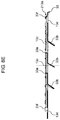
FIG. 8E is a cross-sectional view of the phosphor wheel in FIG. 8B taken along line 8E-8E;
FIG. 8F is a plan view showing an upper face side of a substrate of the phosphor wheel;
FIG. 9A is a perspective view showing a first face side of a phosphor wheel in a third exemplary embodiment;
FIG. 9B is a plan view showing the first face side of the phosphor wheel;
FIG. 9C is a side view of the phosphor wheel;
FIG. 9D is a cross-sectional view of the phosphor wheel in FIG. 9B taken along line 9D-9D;
FIG. 9E is a cross-sectional view of the phosphor wheel in FIG. 9B taken along line 9E-9E;
FIG. 9F is a perspective view showing an upper face side of a disc-shaped member of the phosphor wheel;
FIG. 9G is a plan view showing the upper face side of the disc-shaped member of the phosphor wheel;
FIG. 9H is a side view of the disc-shaped member of the phosphor wheel;
FIG. 9I is a view schematically showing a path of airflow near the phosphor wheel;
FIG. 10A is a perspective view showing a first face side of a phosphor wheel in a fourth exemplary embodiment;
FIG. 10B is a plan view showing the first face side of the phosphor wheel;
FIG. 10C is a side view of the phosphor wheel;
FIG. 10D is a cross-sectional view of the phosphor wheel in FIG. 10B taken along line 10D-10D;
FIG. 10E is a cross-sectional view of the phosphor wheel in FIG. 10B taken along line 10E-10E;
FIG. 10F is a view schematically showing a path of airflow near the phosphor wheel;
FIG. 11A is a perspective view showing an upper face side of a disc-shaped member of a phosphor wheel in a fifth exemplary embodiment;
FIG. 11B is a view schematically showing a path of airflow near the phosphor wheel;
FIG. 12 is a view schematically showing a path of airflow near a phosphor wheel in a sixth exemplary embodiment;
FIG. 13 is a view schematically showing a path of airflow near a phosphor wheel in a seventh exemplary embodiment;
FIG. 14A is a perspective view showing a first face side of a phosphor wheel in a eighth exemplary embodiment;
FIG. 14B is a plan view showing the first face side of the phosphor wheel;
FIG. 14C is a side view of the phosphor wheel; and
FIG. 14D is a cross-sectional view of the phosphor wheel in FIG. 14B taken along line 14D-14D.
DETAILED DESCRIPTION OF THE PREFERRED EMBODIMENTS
Hereinafter, exemplary embodiments will be described, in detail, with reference to the drawings as necessary. However, description that is in more detail than necessary is occasionally omitted. For example, detailed description about already well-known matters and overlapped description about the substantially same configurations are occasionally omitted. This is because the following description is avoided from being unnecessarily redundant, and a person skilled in the art is made to easily understand the present disclosure.
The accompanying drawings and the following description are provided for a person skilled in the art to fully understand the present disclosure, and do not intend to limit the subject matter described in Claims.
First Exemplary Embodiment
A phosphor wheel device equipped with a phosphor wheel in accordance with a first exemplary embodiment of the present disclosure, a light conversion device, and a projector (projection display apparatus) 100 will be described.
1. Structure
1-1. Structure of Projector
FIG. 1 is a view showing a schematic structure of a projector in accordance with a first exemplary embodiment of the present disclosure. Note that, FIG. 1 shows the projector (an example of a projection display apparatus) to which a phosphor wheel of the present disclosure is applied, and the phosphor wheel of the present disclosure is also applicable to projection display apparatuses having the other structures.
Projector 100 is a graphic display device of a DLP (Digital Light Processing) type in which a spatial-light-modulation element (for example, DMD (Digital Micromirror Device) 7 (display element)) is mounted to modulate light according to a video signal. Projector 100 includes blue LDs (laser diode) 2 a and 2 b (light source), various kinds of optical components, and light conversion device 20 including phosphor wheel device 10 that emits fluorescence excited by laser light.
Note that, projector 100 of the present exemplary embodiment employs a three-chip DLP method in which three DMDs 7 corresponding to three primary colors of R, G, and B, respectively, are mounted thereon, but FIG. 1 depicts only one DMD 7 for convenience of description.
As shown in FIG. 1, projector 100 of the present exemplary embodiment includes two blue LDs 2 a and 2 b as a light source. Further, as optical components, projector 100 includes separation mirror 3 a, mirrors 3 b and 3 c, dichroic mirror 3 d, mirrors 3 e, 3 f, and 3 g, lenses 4 a to 4 h, rod integrator 5, TIR (Total Internal Reflection) prism 6 a, color prism 6 b, DMD7, projection lens 8, and light conversion device 20.
Blue LDs 2 a and 2 b, which are the light source of projector 100, each are configured to include a plurality of LDs (m×n pieces) in vertical and horizontal directions. Further, blue LDs 2 a and 2 b are arranged such that their directions are orthogonal to each other. Thus, laser lights emitted from blue LDs 2 a and 2 b travel in directions orthogonal to each other.
Separation mirror 3 a is provided near an intersection at which the laser lights emitted from two blue LDs 2 a and 2 b intersect with each other. By separation mirror 3 a, the laser light emitted from each of blue LDs 2 a and 2 b is separated into two parts, which are deflected in two directions.
The laser lights, which are separated by separation mirror 3 a and travel in the two directions, each are deflected at 90 degrees by mirrors 3 b and 3 c.
Dichroic mirror 3 d, which is constituted by using special photonics materials, reflects light with one specific wavelength and passes light with the other wavelengths. In the present exemplary embodiment, dichroic mirror 3 d reflects red light and green light, while passing the blue laser lights emitted from blue LDs 2 a and 2 b. Herein, the red light and green light are obtained by converting the blue laser lights in phosphor wheel device 10, described later.
Mirrors 3 e, 3 f, and 3 g guide light of three primary colors R, G, and B, which pass through or reflect on dichroic mirror 3 d, to projection lens 8 disposed on the most downstream side.
Lenses 4 a to 4 h converge or collimate the blue laser light, which are emitted from blue LDs 2 a and 2 b serving as the light source, and the red light and green light obtained by converting the blue laser light in phosphor wheel device 10.
Rod integrator 5 makes illumination of incidence light uniform. The light, which have entered rod integrator 5, repeats total internal reflection in an inner peripheral face of rod integrator 5, and are emitted from an emission face as uniform illumination light. Rod integrator 5 is provided such that the light reflected on mirror 3 e enters rod integrator 5.
TIR (total internal reflection) prism 6 a uses its total-internal-reflection function to change a direction in which incident light travels therein.
Color prism 6 b divides the light, which has entered color prism 6 b, into each light of three primary colors R, G, and B, and reflects them to three DMDs 7 that are disposed on its downstream side and corresponding to the respective colors.
Three DMDs 7 are provided to correspond to the three primary colors of R, G, and B one by one. Each of three DMDs 7 modulates the corresponding light, which has entered therein, according to a video signal and emits the modulated light to projection lens 8 through color prism 6 b and TIR (total internal reflection) prism 6 a.
Projection lens 8 is disposed on the most downstream side of optical components mounted on projector 100. By projection lens 8, the light that has entered projection lens 8 through TIR prism 6 a, DMD 7, and color prism 6 b is expanded and projected on a screen (not shown).
Light conversion device 20 is an apparatus that converts the blue laser lights emitted from blue LDs 2 a and 2 b, described later, into red light and green light through a fluorescent substance, and includes phosphor wheel device 10. Note that, a structure of light conversion device 20 including phosphor wheel device 10 will be described in detail in the later stage.
<Projection of an Image by Projector 100>
The laser lights emitted from two blue LDs 2 a and 2 b are separated into two parts, which are deflected in two directions, by separation mirror 3 a disposed near an intersection at which the laser lights intersect with each other.
A first blue laser light, which is one of the two parts, passes through dichroic mirror 3 d trough lens 4 c, mirror 3 c, and lens 4 d. Subsequently, after passing through lens 4 e, the first blue laser light is reflected at 90 degrees by mirror 3 e, and enters rod integrator 5.
A second blue laser light passes through dichroic mirror 3 d through lens 4 a, mirror 3 b, and lens 4 b, and is emitted to phosphor layer 16 of phosphor wheel 13 in phosphor wheel device 10. At this time, red fluorescent substance and green fluorescent substance of phosphor layer 16 are excited by the second blue laser light, and emits red light and green light. In other words, the second blue laser light is converted into red light and green light.
At that time, phosphor wheel 13 is driven to rotate by motor 14 in order to disperse energy. This makes it possible to prevent the fluorescent substances from burning, when the red and green fluorescent substances are irradiated with the blue laser light.
In dichroic mirror 3 d, the red light and green light, which are obtained by converting the second blue laser light, are reflected at 90 degrees and enter rod integrator 5.
The each light of three primary colors R, G, and B is mixed in rod integrator 5 and enters a boundary layer of TIR prism 6 a through lens 4 f, mirrors 3 f and 3 g, and lens 4 h. The each light of three primary colors R, G, and B is reflected inside TIR prism 6 a and travel to color prism 6 b, because TIR prism 6 a reflects light at a total-internal-reflection angle.
In color prism 6 b, the each light of three primary colors R, G, and B are separated one by one, and each light enters a corresponding one of three DMDs 7.
Each light forming an image in DMD 7 and reflected is synthesized by color prism 6 b, passes through the boundary layer of TIR prism 6 a, and enters projection lens 8, so that the image is projected on a projection screen.
In projector 100 of the present exemplary embodiment, the blue laser lights emitted from blue LDs 2 a and 2 b, which serve as an excitation light source, excite red fluorescent substance and green fluorescent substance that are contained in phosphor layer 16 provided on a surface of phosphor wheel 13, and generate red light and green light. At this time, all of energies of the blue laser light are not converted into fluorescence luminescence, but a part of them is converted into thermal energy. This may increase temperature of the red fluorescent substance and the green fluorescent substance.
Herein, a fluorescent substance is likely to be deteriorated in optical conversion efficiency when temperature increases. Further, heat discoloration or the like may occur in a binder that fixes the fluorescent substance on phosphor wheel 13 to form phosphor layer 16. For that reason, phosphor wheel 13 is driven to rotate by motor 14 in order to prevent the increase in heat of the fluorescent substance.
As higher brightness is required for projector 100, however, the output of excitation light (laser light) is increased. Accordingly, phosphor layer 16 and the surrounding area thereof cannot be cooled sufficiently even if phosphor wheel 13 is driven to rotate. Therefore, it is necessary to blow cooling air over phosphor layer 16 and the surrounding area thereof to cool the fluorescent substance actively.
Thus, the present exemplary embodiment is configured to supply cooling air to phosphor layer 16 of phosphor wheel 13. Although concrete configuration is described later, the present exemplary embodiment provides blades 33 a, 33 b, and 33 f, while providing openings 13 c and 13 d formed through phosphor wheel 13 in a thickness direction (see FIG. 7A).
Note that, structures of phosphor wheel device 10 and light conversion device 20 including phosphor wheel device 10 will be described, in detail, in the later stage.
1-2. Structure of Light Conversion Device
A structure of the light conversion device will be described with reference to FIGS. 2, 3, 4A and 4B. FIG. 2 is a cross-sectional view showing a structure of a principal part of light conversion device 20. FIG. 3 is a perspective view of light conversion device 20. FIG. 4A is perspective views showing structures of a heat absorber disposed inside the light conversion device and a heat dissipater thermally connected to the heat absorber. FIG. 4B is a plan view of the heat absorber and the heat dissipater in FIG. 4A.
As shown in FIG. 2, light conversion device 20 includes phosphor wheel device 10 described later, heat absorber 21, heat dissipater 22, optical lens 23, and heat pipe 24.
Phosphor wheel device 10 converts the blue laser light into red light and green light by irradiating a fluorescent substance with blue laser lights emitted from blue LDs 2 a and 2 b. Note that, the detailed structure of phosphor wheel device 10 will be described in the later stage.
As shown in FIG. 2, heat absorber 21 is disposed inside casing unit 11 of phosphor wheel device 10. Heat absorber 21 has a fin structure through which airflow formed in light conversion device 20 passes, and absorbs heat from the airflow including heat generated in phosphor layer 16 of phosphor wheel 13. Heat absorber 21 is fixed to outer cylindrical portion 11 b and bottom portion 11 d with a screw. Herein, outer cylindrical portion 11 b is included in casing unit 11 of phosphor wheel device 10 shown in FIG. 3. Further, as shown in FIGS. 4A and 4B, heat absorber 21 has a plurality of fins 21 a, and is thermally connected to heat dissipater 22 via heat pipe 24.
A plurality of fins 21 a are constituted by metal with high thermal conductivity, and radially arranged in a plan view, as shown in FIG. 4B.
Thus, the airflow entering a gap between phosphor wheel 13 and lid portion 11 a through a plurality of openings 13 c, which are formed through phosphor wheel 13, can be guided to the outside in a radial direction. At this time, phosphor layer 16 is provided on a face (first face) of phosphor wheel 13 that faces lid portion 11 a, thereby making it possible to send the airflow to phosphor layer 16 and its vicinity, effectively. Accordingly, the heat generated in the fluorescent substance can be cooled efficiently.
Further, when the airflow passes through between the plurality of fins 21 a, temperature of the airflow can be reduced because the heat contained in the airflow is transferred to a fin 21 a side.
In an inner peripheral face of heat absorber 21, wall portion 21 b is positioned on an outer peripheral side of blade 33 b. Wall portion 21 b functions as a wall portion that prevents the airflow, which is generated by blade 33 b during rotation of phosphor wheel 13, from flowing into the outer peripheral side, i.e., a second face (face on an opposite side of phosphor wheel 13 from the first face on which phosphor layer 16 is provided) side.
Thus, the airflow generated by blade 33 b during rotation of phosphor wheel 13 can be guided to the first face side on which phosphor layer 16 is formed through opening 13 c of phosphor wheel 13, efficiently.
As shown in FIG. 2, heat dissipater 22 is disposed outside casing unit 11 of phosphor wheel device 10. As shown in FIG. 3 or other figures, heat dissipater 22 is thermally connected to heat absorber 21 via heat pipe 24. Thus, the heat of the airflow, which is absorbed in heat absorber 21, is dissipated to the outside of casing unit 11. Further, heat dissipater 22 has a fin structure including a plurality of fins 22 a disposed on an outer peripheral face of heat dissipater 22.
The plurality of fins 22 a, which are constituted by metal with high thermal conductivity, are arranged along a direction perpendicular to a longitudinal direction of heat pipe 24, as shown in FIGS. 4A and 4B. Thus, the heat is dissipated to the outside air from casing unit 11.
As shown in FIGS. 2 and 3, optical lens 23 is attached to an opening portion formed in lid portion 11 a of casing unit 11 via optical lens holding component 23 a. As shown in FIG. 1, the excitation light that excites the fluorescent substance of phosphor layer 16 of phosphor wheel 13 passes through optical lens 23. In addition to this, the light emitted from the fluorescent substance of phosphor layer 16 is converged and guided to dichroic mirror 3 d by optical lens 23.
As shown in FIGS. 4A and 4B, heat pipe 24 connects heat absorber 21 and heat dissipater 22 thermally. Inside heat pipe 24, a hollow space is formed. A small amount of water is enclosed in the hollow space. When receiving heat on a heat absorber 21 side, the water evaporates and moves to a heat dissipater 22 side as vapor. The vapor that has moved to the heat dissipater 22 side is cooled and liquefied in heat dissipater 22, and then turned into water. Herein, after the vapor is cooled on the heat dissipater 22 side and turned into water, the water is moved into the hollow space due to a capillary phenomenon, and returns back to heat absorber 21.
In other words, inside heat pipe 24, the small amount of water is evaporated on the heat absorber 21 side and liquefied on the heat dissipater 22 side, i.e., functions as a cooling medium.
1-3. Structure of Phosphor Wheel Device
A structure of phosphor wheel device 10 will be described with reference to FIGS. 5 and 6, in addition to each of the above-mentioned figures. FIG. 5 is a cross-sectional view showing an inside structure of the light conversion device in FIG. 2. FIG. 6 is a perspective view showing a structure of a casing unit of the light conversion device in FIG. 2.
As shown in FIG. 2, phosphor wheel device 10 includes casing unit 11, phosphor wheel 13, motor 14, and pressurization fan 15.
Casing unit 11, which has a cylindrical shape (see FIG. 3), forms an enclosed space thereinside. The enclosed space accommodates phosphor wheel 13, motor 14, heat absorber 21, and the like. As shown in FIG. 5, casing unit 11 has outer cylindrical portion 11 b and inner cylindrical portion 11 c that are substantially-concentrically arranged. Both ends of outer cylindrical portion 11 b and inner cylindrical portion 11 c are communicated with each other in a direction of axis X parallel to a rotation center of phosphor wheel 13, and form a circulation path of airflow.
Furthermore, at least a portion of casing unit 11 in contact with the outside air is formed of metal. Thus, even if the inside of casing unit 11 is warmed by heat generated in a fluorescent substance portion of phosphor layer 16 of phosphor wheel 13 provided in casing unit 11, the heat can be efficiently dissipated to the outside through the above-mentioned portion of casing unit 11, which is formed of metal with high thermal conductivity. Note that, it is preferred that the above-mentioned portion of casing unit 11, which is formed of metal, functions as lid portion 11 a on a phosphor wheel 13 side, for example.
As shown in FIG. 5, before entering heat absorber 21, the airflow to which the heat generated in phosphor layer 16 is transferred passes through the vicinity of lid portion 11 a disposed close to phosphor layer 16 of phosphor wheel 13. Thus, even if lid portion 11 a is heated by the airflow that has passed through the vicinity of phosphor layer 16 of phosphor wheel 13 and heated, the heat of lid portion 11 a can be dissipated to the outside, effectively. As a result, as compared with other members (outer cylindrical portion 11 b, inner cylindrical portion 11 c, bottom portion 11 d) that constitute casing unit 11, the heat of the airflow can be dissipated to the outside more effectively.
As shown in FIG. 3, lid portion 11 a is a substantially square-plate shaped member. Further, as shown in FIG. 2, lid portion 11 a is attached to casing unit 11 so as to cover a face of phosphor wheel 13 on a phosphor layer 16 side. Further, opening 11 aa into which above-mentioned optical lens 23 is inserted is formed in lid portion 11 a. The blue laser light and fluorescence (red, green) pass through optical lens 23.
Opening 11 aa is a through hole formed to face phosphor layer 16 of phosphor wheel 13 in lid portion 11 a. Optical lens 23 is attached to opening 11 aa via optical lens holding component 23 a.
As shown in FIGS. 3 and 6, outer cylindrical portion 11 b is a substantially cylindrical shaped member that forms a side face of casing unit 11.
Inner cylindrical portion 11 c is a cylindrical member that is concentrically arranged with respect to outer cylindrical portion 11 b, and disposed on an inner circumferential side of outer cylindrical portion 11 b. Inner cylindrical portion 11 c is disposed adjacent to an inner circumferential side of heat absorber 21. Furthermore, inner cylindrical portion 11 c is formed to have a dimension smaller than that of outer cylindrical portion 11 b in the direction of axis X. Thus, both ends of outer cylindrical portion 11 b and inner cylindrical portion 11 c are communicated with each other in the direction of axis X.
As shown in FIG. 5, bottom portion 11 d is attached to outer cylindrical portion 11 b to cover a face on an opposite side of casing unit 11 from the face on which lid portion 11 a is provided in the direction of axis X.
Updraft guide 11 e is a guide member for inverting and raising the airflow that has passed through heat absorber 21 and cooled. Updraft guide 11 e is provided on bottom portion 11 d to project toward an inner space side of casing unit 11. Updraft guide 11 e has a substantially cone shape centered on axis X. Along updraft guide 11 e, the airflow that has flowed into the inner circumferential side of inner cylindrical portion 11 c from the outer circumferential side thereof is guided to rise up, using wind force of pressurization fan 15.
Accordingly, the airflow generated by blades 33 a and 33 b, according to rotation of phosphor wheel 13, flows out from the inner circumferential side of inner cylindrical portion 11 c and passes through opening 13 c of phosphor wheel 13 and communicating part 11 g located on a phosphor wheel 13 side. Subsequently, the airflow is guided to the outside in the radial direction, while passing through the vicinity of phosphor layer 16 of phosphor wheel 13. Then, the airflow passes through opening 13 d and the peripheral portion of phosphor wheel 13, and passes through the inside of heat absorber 21 while moving downward along axis X, and then is cooled. In other words, opening 13 d is a passage for sending air from the first face to the second face. The airflow, which has passed through heat absorber 21 and cooled, passes through communicating part 11 h located on an opposite side of inner cylindrical portion 11 c from phosphor wheel 13, and returns back to the inner circumferential side of inner cylindrical portion 11 c. In this way, a circulation path of the airflow generated by blades 33 a and 33 b is formed in the inner space of casing unit 11 during rotation of phosphor wheel 13.
FIG. 7A is a perspective view showing a first face side of the phosphor wheel. FIG. 7B is a plan view showing the first face side of the phosphor wheel.
As shown in FIGS. 7A and 7B, phosphor wheel 13 is a disc-shaped rotating member. Phosphor wheel 13 has phosphor layer 16, a plurality of openings 13 c (an example of a second opening), a plurality of openings 13 d (an example of a first opening), the same number of blades 33 a as the plurality of openings 13 c, the same number of blades 33 b (an example of a second blade) as the plurality of openings 13 c, and the same number of blades 33 f (an example of a first blade) as the plurality of openings 13 d.
The plurality of openings 13 c, blades 33 a, and blades 33 b are arranged at first predetermined angular intervals in a circumferential direction about a rotation center of phosphor wheel 13 on an inner circumferential side of phosphor layer 16.
The plurality of openings 13 d and blades 33 f are arranged at second predetermined angular intervals in the circumferential direction about the rotation center of phosphor wheel 13 on an outer circumferential side of phosphor layer 16. The first predetermined angle and the second predetermined angle may be the same, or may be different from each other.
FIG. 7C is a side view of phosphor wheel 13. FIG. 7D is a cross-sectional view of phosphor wheel 13 in FIG. 7B taken along line 7D-7D. FIG. 7E is a cross-sectional view of phosphor wheel 13 in FIG. 7B taken along line 7E-7E.
As shown in FIGS. 7C through 7E, disc-shaped substrate 13 a and disc-shaped member 33 are stacked to constitute phosphor wheel 13.
FIG. 7F is a perspective view showing an upper face side of substrate 13 a of phosphor wheel 13. FIG. 7G is a plan view showing the upper face side of substrate 13 a of phosphor wheel 13.
As shown in FIGS. 7F and 7G, substrate 13 a has center hole 13 h provided at a rotation center of circular substrate 13 a, phosphor layer 16, a plurality of openings 13 ca, and a plurality of openings 13 da.
The plurality of openings 13 ca each are an opening for forming opening 13 c of phosphor wheel 13 on a substrate 13 a side. The plurality of openings 13 ca are arranged at the above-mentioned first predetermined angular intervals in a circumferential direction about the rotation center of substrate 13 a.
The plurality of openings 13 da each are an opening for forming opening 13 d of phosphor wheel 13 on the substrate 13 a side. Note that, each of the plurality of openings 13 da is larger than opening 13 d (opening 33 db of disc-shaped member 33 described later), and one opening 13 da is provided to every two openings 13 d. Accordingly, the plurality of openings 13 da are arranged at double the above-mentioned second predetermined angular intervals in the circumferential direction about the rotation center of substrate 13 a.
A fluorescent substance is applied annularly to form phosphor layer 16. As mentioned above, phosphor layer 16 converts the blue laser lights emitted from blue LDs 2 a and 2 b into red light and green light, and emits the red light and green light from phosphor wheel 13.
FIG. 7H is a perspective view showing an upper face side of disc-shaped member 33 of phosphor wheel 13. FIG. 7I is a plan view showing the upper face side of disc-shaped member 33 of phosphor wheel 13. FIG. 7J is a side view of disc-shaped member 33 of phosphor wheel 13. FIG. 7K is a cross-sectional view of disc-shaped member 33 in FIG. 7I taken along line 7K-7K. FIG. 7L is a cross-sectional view of disc-shaped member 33 in FIG. 7I taken along line 7L-7L. FIG. 7M is a view schematically showing a path of airflow near phosphor wheel 13. In (a) of FIG. 7M, a cross-section of phosphor wheel 13 taken along a radial direction is shown. In (b) of FIG. 7M, there is shown a cross-section of a portion at which opening 13 c and blades 33 a and 33 b are provided in phosphor wheel 13 taken along a circumferential direction. In (c) of FIG. 7M, there is shown a cross-section of a portion at which opening 13 d and blade 33 f are provided in phosphor wheel 13 taken along a circumferential direction. Note that, in phosphor wheel 13 of FIG. 7M, disc-shaped member 33 and substrate 13 a are collectively illustrated as one member.
As shown in FIGS. 7H through 7J, disc-shaped member 33 has center hole 33 h provided at the rotation center of circular disc-shaped member 33, a plurality of openings 33 cb, a plurality of openings 33 db, the same number of blades 33 a and 33 b as the plurality of openings 33 cb, and the same number of blades 33 f as the plurality of openings 33 db.
The plurality of openings 33 cb each are an opening for forming opening 13 c of phosphor wheel 13 on a disc-shaped member 33 side. The plurality of openings 33 cb are arranged at the above-mentioned first predetermined angular intervals in a circumferential direction about the rotation center of disc-shaped member 33.
The plurality of openings 33 db each are an opening for forming opening 13 d of phosphor wheel 13 on the disc-shaped member 33 side. The plurality of openings 33 db are arranged at the above-mentioned second predetermined angular intervals in the circumferential direction about the rotation center of disc-shaped member 33.
As shown in FIGS. 7I and 7L, blade 33 a is provided to extend upward from a front-side edge in a rotation direction of opening 33 cb. Further, blade 33 a is elongated in a radial direction along the front-side edge in the rotation direction of opening 33 cb.
As shown in FIGS. 7I and 7L, blade 33 b is provided to extend obliquely downward from a rear-side edge in the rotation direction of opening 33 cb toward a front side in the rotation direction of opening 33 cb. Further, blade 33 b is elongated in the radial direction along the rear-side edge in the rotation direction of opening 33 cb.
As shown in FIGS. 7I and 7M, blade 33 f is provided to extend obliquely upward from a rear-side edge in a rotation direction of opening 33 db toward a front side in the rotation direction of opening 33 db. Further, blade 33 f is elongated in the radial direction along the rear-side edge in the rotation direction of opening 33 db.
Herein, disc-shaped member 33 is mode of aluminum, for example. Openings 33 cb and 33 db are formed by cutting into disc-shaped member 33. Blades 33 a, 33 b, and 33 f are formed by cutting and raising a sheet of disc-shaped member 33 made of aluminum. More specifically, blade 33 a is formed by bending, to the upper face side, a portion obtained by cutting into disc-shaped member 33 to form opening 33 cb. Blade 33 b is formed by bending, to the lower face side, the portion obtained by cutting into disc-shaped member 33 to form opening 33 cb. Blade 33 f is formed by bending, to the upper face side, a portion obtained by cutting into disc-shaped member 33 to form opening 33 db.
Disc-shaped member 33 is stacked on disc-shaped substrate 13 a such that center hole 33 h is aligned with center hole 13 h of disc-shaped substrate 13 a, thereby making it possible to align disc-shaped member 33 with substrate 13 a. Further, disc-shaped member 33 is stacked on substrate 13 a such that blades 33 a and 33 f are inserted into openings 13 ca and 13 da on the substrate 13 a side, thereby also making it possible to align disc-shaped member 33 with substrate 13 a in the circumferential direction.
Disk-shaped member 33 and substrate 13 a, which are stacked on each other, are sandwiched by a predetermined fixed member from upper and lower sides in the axial direction.
According to phosphor wheel 13 with the above-mentioned structure, when phosphor wheel 13 is driven to rotate, airflow is generated in casing unit 11 to flow upward in the axial direction by pressurization fan 15 and blade 33 b integrated with phosphor wheel 13, as shown in FIG. 5.
In the present exemplary embodiment, opening 13 c is formed to correspond to blade 33 b in phosphor wheel 13. Therefore, the airflow generated by blade 33 b is sent, through opening 13 c, to the first face side of phosphor wheel 13 on which phosphor layer 16 is formed, and further sent to the phosphor-layer 16 side by blade 33 a.
Further, in the enclosed space formed in casing unit 11, after being heated near phosphor layer 16 of phosphor wheel 13, the airflow generated by blade 33 b passes through heat absorber 21 disposed in a space between outer cylindrical portion 11 b and inner cylindrical portion 11 c.
At this time, heat exchange is performed between the heated air and the small amount of water enclosed into heat pipe 24 connected to heat absorber 21, so that the air is cooled. After that, the cooled air moves to the inner circumferential side of inner cylindrical portion 11 c, and is sent out toward the phosphor layer 16 side of phosphor wheel 13 through opening 13 c.
Thus, as shown in FIG. 7M, the airflow that is generated by blade 33 b and flows along the axial direction passes through opening 13 c, and is guided to the first face side on which phosphor layer 16 is provided, and then moved outward in the radial direction by blade 33 a.
Herein, motor 14 for driving to rotate phosphor wheel 13 is disposed on a path of the airflow cooled by heat absorber 21, as shown in FIG. 5. Accordingly, even if heat is generated in motor 14 by continuous rotation of phosphor wheel 13, the cooling air can cool motor 14 effectively.
Further, pressurization fan 15 is disposed within a circulation path of airflow, which is formed in casing unit 11, and sends air along a direction of airflow in the circulation path. In other words, as shown in FIG. 5, pressurization fan 15 is disposed to send air along a direction of airflow generated by blade 33 b. Further, pressurization fan 15 is disposed between phosphor wheel 13 and updraft guide 11 e in casing unit 11. In other words, in a circulation path of the airflow that is generated by blade 33 b and flows along the axial direction, pressurization fan 15 is disposed on the most downstream side. This makes it possible to strengthen airflow on the most downstream side, because the airflow generated by blade 33 b is most weakened on the most downstream side. As a result, the speed of airflow is increased near phosphor layer 16 of phosphor wheel 13, motor 14, or the like, which is a place where a large amount of heat is generated in casing unit 11, so that the cooling effect is more improved.
As mentioned above, blade 33 a is located on the face (first face) on which phosphor layer 16 is provided, i.e., the face located on an opposite side to blade 33 b, and provided to be adjacent to opening 13 c and extend along the radial direction. As shown in FIG. 5, to dissipate the heat generated in casing unit 11 when the fluorescent substance of phosphor layer 16 of phosphor wheel 13 is excited, blade 33 a forms airflow flowing outward in the radial direction.
In more detail, blade 33 a guides airflow such that the airflow flows outward in in the radial direction. Herein, the airflow is generated by blade 33 b and above-mentioned pressurization fan 15, flows along the axial direction, passes through the plurality of openings 13 c formed in phosphor wheel 13, and moves to the face side on which phosphor layer 16 is provided.
Thus, if the speed of airflow is increased near the surface of phosphor layer 16 of phosphor wheel 13, the cooling effect will be more improved than before, effectively.
Further, as shown in FIG. 2, blade 33 a is located on the face on which phosphor layer 16 is provide so as to face optical lens 23, and disposed close to optical lens 23. Accordingly, the height of blade 33 a is determined such that blade 33 a does not tough optical lens 23. Therefore, in the present exemplary embodiment, even if optical lens 23 is disposed close to the face on which phosphor layer 16 is provided, cooling effect of phosphor layer 16 can be improved.
1-4. Circulation of Airflow Generated by Blade
As mentioned above, in the present exemplary embodiment, blades 33 a and 33 f and blade 33 b are formed integrally with each other and rotated due to rotation of phosphor wheel 13, thereby generating airflow in casing unit 11. Herein, blades 33 a and 33 f are provided on the first face side of phosphor wheel 13 mounted on phosphor wheel device 10, and blade 33 b is provided on the second face side.
In other words, the airflow generated by blade 33 b is formed to flow upward in FIG. 5, and passes through opening 13 c of phosphor wheel 13, as shown in a FIG. 5.
Note that, although the airflow formed by blade 33 b is likely to flow outward in the radial direction due to centrifugal force or the like, wall portion 21 b of heat absorber 21 prevents the airflow from flowing outward in the radial direction. Now, wall portion 21 b is disposed close to blade 33 b on an outer peripheral side of blade 33 b in the radial direction. This prevents the air from flowing to the outer peripheral side of blade 33 b in the radial direction, so that the airflow can be guided to opening 13 c efficiently.
The airflow that has passed through opening 13 c of phosphor wheel 13 is sent outward in the radial direction about axis X by blade 33 a.
At this time, when passing through near the surface of phosphor layer 16, the airflow moving along phosphor layer 16 of phosphor wheel 13 is heated by heat of the fluorescent substance.
The airflow heated by the fluorescent substance passes through opening 13 d of phosphor wheel 13, moves downward in FIG. 5, and passes through a gap between fins 21 a of heat absorber 21.
At this time, heat absorber 21 absorbs heat from the heated airflow, and cools it.
The airflow cooled in heat absorber 21 moves along a face of bottom portion 11 d from a lower end of heat absorber 21 in the direction of axis X, and is guided to a phosphor wheel 13 side along updraft guide 11 e.
At this time, as shown in FIG. 5, the airflow rising up along updraft guide 11 e is accelerated and moved by pressurization fan 15.
The airflow accelerated by pressurization fan 15 flows through near motor 14 and cools motor 14, and then moves to the second face of phosphor wheel 13 again. As mentioned above, the airflow that has moved to the second face of phosphor wheel 13 is moved to the face on a phosphor layer 16 side through opening 13 c by blade 33 b. This makes it possible to cool the heat generated in the fluorescent substance of phosphor layer 16 of phosphor wheel 13, constantly.
Herein, to cool the heat generated in phosphor layer 16 of phosphor wheel 13 efficiently, a fan is usually provided such that air hits the front of phosphor layer 16 directly. In such a structure, however, the arrangement of a fan may make it difficult to secure a space for accommodating optical lens 23, which is disposed close to phosphor layer 16 of phosphor wheel 13, as shown in FIG. 7L. Alternatively, an apparatus is likely to be enlarged.
In phosphor wheel device 10 of the present exemplary embodiment and light conversion device 20 including the same, blades 33 a, 33 b, and 33 f for forming the airflow to cool phosphor layer 16 of phosphor wheel 13 each are provided on the face on which phosphor layer 16 of phosphor wheel 13 is provided or a face on an opposite side to the face on which phosphor layer 16 is provided, as mentioned above. Furthermore, in the present exemplary embodiment, to guide the airflow generated by blade 33 b to the phosphor layer 16 side on which blade 33 a is provided, opening 13 c is provided so as to correspond to blade 33 b of phosphor wheel 13.
Accordingly, the space for accommodating optical lens 23 can be secured on the phosphor layer 16 side of phosphor wheel 13. Addition to this, the airflow passing through near phosphor layer 16 can be formed by blades 33 a and 33 f provided on the first face side of phosphor layer 16.
Especially, in the present exemplary embodiment, blade 33 f is provided close to the outer circumference of phosphor layer 16, and formed such that blade 33 f extends forwardly and upwardly in the rotation direction from the first face. Thus, the air that has passed through phosphor layer 16 and flowed to the outer circumferential side is drawn to the second face side of phosphor wheel 13. This makes it easier to cause the air to flow through near the surface of phosphor layer 16 at high speed, as shown in FIG. 7M. Therefore, the heat generated in phosphor layer 16 can be absorbed effectively.
According to the present exemplary embodiment that has the above-mentioned structure, blades 33 a, 33 b, and 33 f, and optical lens 23 can be accommodated together without enlarging an apparatus. In addition to this, heat generated in a fluorescent substance of phosphor layer 16 can be cooled effectively.
2. Effect
Phosphor wheel 13 of the present exemplary embodiment includes a first face that has phosphor layer 16, a second face located on an opposite side to the first face, blade 33 f (first blade) provided to project from the first face, and opening 13 d (passage, first opening) provided to pass through phosphor wheel 13 between the first face and the second face. Blade 33 f is provided to send air on a second face side to the first face side through opening 13 d during rotation of phosphor wheel 13.
This makes it possible to dissipate heat generated in a fluorescent substance of phosphor layer 16 to the second face side opposite to the first face side. Therefore, cooling performance of phosphor wheel 13 is improved.
Phosphor wheel 13 of the present exemplary embodiment further includes opening 13 c (second opening) provided to pass through phosphor wheel 13 between the first face and the second face, and blade 33 b (second blade) provided to project from the second face. Blade 33 b is provided to send cooling air, which is supplied to the second face side, to the first face side through opening 13 c during rotation of phosphor wheel 13.
This makes it possible to send cooling air to the first face side on which phosphor layer 16, which generates heat, is provided. Therefore, cooling performance of phosphor wheel 13 is more improved.
In phosphor wheel 13 of the present exemplary embodiment, phosphor layer 16 has an annular shape centered on rotation axis X of phosphor wheel 13, and opening 13 d (first opening) and opening 13 c (second opening) are disposed to sandwich phosphor layer 16 in the radial direction of the phosphor wheel 13.
Thus, the cooling air, which is sent to the first face side through opening 13 c, approaches phosphor layer 16 and passes through above phosphor layer 16, and then the air is discharged to the second face side through opening 13 d. Accordingly, phosphor layer 16 can be cooled efficiently. Therefore, cooling performance of phosphor wheel 13 is more improved.
In phosphor wheel 13 of the present exemplary embodiment, opening 13 d (first opening) is disposed on an outer circumferential side of phosphor layer 16, and opening 13 c (second opening) is disposed on an inner circumferential side of phosphor layer 16.
Thus, the cooling air, which is sent to the first face side through opening 13 c, automatically flows toward opening 13 d disposed on the outer circumferential side due to centrifugal force caused by rotation of phosphor wheel 13. Therefore, cooling performance of phosphor wheel 13 is more improved.
The present disclosure further provides a phosphor wheel including the phosphor wheel in the present disclosure, a phosphor wheel device including the same, a light conversion device, and a projection display apparatus.
In the above-mentioned description, the first exemplary embodiment of the phosphor wheel in the present disclosure has been described. In the following, second to eighth exemplary embodiments will be described as a variation of the phosphor wheel in the present disclosure. Note that, in description of the second to eighth exemplary embodiments, the same reference numerals are assigned to components having a similar function.
Second Exemplary Embodiment
A second exemplary embodiment will be described with reference to FIGS. 8A through 8F. FIG. 8A is a perspective view showing a first face side of a phosphor wheel in the second exemplary embodiment. FIG. 8B is a plan view showing the first face side of the phosphor wheel. FIG. 8C is a side view of the phosphor wheel. FIG. 8D is a cross-sectional view of the phosphor wheel in FIG. 8B taken along line 8D-8D. FIG. 8E is a cross-sectional view of the phosphor wheel in FIG. 8B taken along line 8E-8E. FIG. 8F is a plan view showing an upper face side of a substrate of the phosphor wheel.
In phosphor wheel 13 of the first exemplary embodiment, as described in FIGS. 7A through 7G, substrate 13 a expands up to the outer circumferential side of phosphor layer 16, and an annular portion on the outer circumferential side is provided with opening 13 da into which blade 33 f of disc-shaped member 33 is fitted. On the other hand, in phosphor wheel 213 of the second exemplary embodiment, as shown in FIG. 8F, substrate 213 a has no annular portion and openings on the outer circumferential side of phosphor layer 16. Note that, in the present exemplary embodiment, disc-shaped member 33 in the first exemplary embodiment, shown in FIG. 7H or the like, is employed as a disc-shaped member. Substrate 213 a in FIG. 8F and disc-shaped member 33 in the first exemplary embodiment, shown in FIG. 7H or the like, are combined to obtain phosphor wheel 213 of the second exemplary embodiment, which is shown in FIGS. 8A through 8E. As shown in FIGS. 8A through 8E, phosphor wheel 213 in the present exemplary embodiment does not have substrate 213 a on an upper face side of an outer circumferential portion of disc-shaped member 33, and opening 33 db and blade 33 f of disc-shaped member 33 are exposed to the outside.
Such a structure makes it possible to generate the same airflow as in the first exemplary embodiment described in FIG. 7M, while simplifying the structure of substrate 213 a. Further, the same cooling effect as in the first exemplary embodiment is obtained.
Third Exemplary Embodiment
A third exemplary embodiment will be described with reference to FIGS. 9A through 9I. FIG. 9A is a perspective view showing a first face side of a phosphor wheel in the third exemplary embodiment. FIG. 9B is a plan view showing the first face side of the phosphor wheel. FIG. 9C is a side view of the phosphor wheel. FIG. 9D is a cross-sectional view of the phosphor wheel in FIG. 9B taken along line 9D-9D. FIG. 9E is a cross-sectional view of the phosphor wheel in FIG. 9B taken along line 9E-9E. FIG. 9F is a perspective view showing an upper face side of disc-shaped member 333 of the phosphor wheel. FIG. 9G is a plan view showing the upper face side of the disc-shaped member of the phosphor wheel. FIG. 9H is a side view of the disc-shaped member of the phosphor wheel. FIG. 9I is a view schematically showing a path of airflow near the phosphor wheel. In (a) of FIG. 9I, a cross-section of the phosphor wheel taken along a radial direction is shown. In (b) of FIG. 9I, there is shown a cross-section of a portion in which opening 13 c and blades 33 a and 33 b are provided in the phosphor wheel taken along a circumferential direction. In (c) of FIG. 9I, there is shown a cross-section of a portion in which opening 13 d and blades 333 f are provided in the phosphor wheel taken along a circumferential direction. Note that, in phosphor wheel 313 in FIG. 9, a disc-shaped member and a substrate are collectively illustrated as one member.
In phosphor wheel 13 of the first exemplary embodiment, as described in FIGS. 7A through 7G, blade 33 f of disc-shaped member 33 is provided to project from the first face (upper face). On the other hand, in phosphor wheel 313 in the third exemplary embodiment, disc-shaped member 333 has blade 333 f that is provided to project to a lower face side, as shown in FIGS. 9F through 9H. Specifically, blade 333 f is extended rearwardly and downwardly from a front end in the rotation direction of opening 13 d. Note that, in the present exemplary embodiment, substrate 13 a in the first exemplary embodiment, shown in FIGS. 7F, 7G, and the like, is employed as a substrate. Disc-shaped member 333 in FIGS. 9F through 9H and substrate 13 a in the first exemplary embodiment, shown in FIGS. 7F, 7G, and the like, are combined to obtain phosphor wheel 313 of the third exemplary embodiment, which is sown in FIGS. 9A through 9E. As shown in FIGS. 9A through 9E, in phosphor wheel 313 of the present exemplary embodiment, blade 333 f of disc-shaped member 333 is projected from the second face (lower face) of phosphor wheel 313.
According to the above-mentioned structure, as shown in FIG. 9I, the air pressure on a rear side in the rotation direction of blade 333 f is more decreased than that of the surrounding area of the rear side during rotation of phosphor wheel 313. Thus, the air on the first face side (upper face side) flows into the second face side (lower face side) through opening 13 d. This makes it possible to generate airflow similar to that described in FIG. 7M of the first exemplary embodiment. Therefore, the same cooling effect as in the first exemplary embodiment can be obtained.
In other words, phosphor wheel 313 of the present exemplary embodiment includes a first face that has phosphor layer 16, a second face located on an opposite side to the first face, blade 333 f (first blade) provided to project from the second face, and opening 13 d (passage, first opening) provided to pass through phosphor wheel 313 between the first face and the second face. Blade 333 f is provided to send the air on the first face side to the second face side through opening 13 d during rotation of phosphor wheel 313. This makes it possible to dissipate the heat generated in a fluorescent substance of a phosphor layer on the first face side to a second face side on an opposite side to the first face. Therefore, the cooling performance of phosphor wheel 13 is improved.
Note that, as mentioned above, blade 333 f is formed to project from the second face, and differs from blade 33 f of phosphor wheel 13 in the first exemplary embodiment, which projects from the first face. Further, blade 33 b, which corresponds to the second blade, may also be formed to project from the first face, rather than from the second face. Specifically, the second blade is formed to extend rearwardly and upwardly from a front end in the rotation direction of opening 13 c. Thus, during rotation of the phosphor wheel, the air pressure on the rear side of the second blade is more decreased than that of the surrounding area of the rear side, so that the air on the second face flows into the first face side through opening 13 c. In this case, although being formed in a front end in the rotation direction of opening 13 c in the first to third exemplary embodiments, blade 33 a is formed in a rear end in the rotation direction of opening 13 c to send the air, which flows into the first face side, to above phosphor layer 16 as a guide.
Fourth Exemplary Embodiment
A fourth exemplary embodiment will be described with reference to FIGS. 10A through 10F. FIG. 10A is a perspective view showing a first face side of a phosphor wheel in the fourth exemplary embodiment. FIG. 10B is a plan view showing the first face side of the phosphor wheel. FIG. 10C is a side view of the phosphor wheel. FIG. 10D is a cross-sectional view of the phosphor wheel in FIG. 10B taken along line 10D-10D. FIG. 10E is a cross-sectional view of the phosphor wheel in FIG. 10B taken along line 10E-10E. FIG. 10F is a view schematically showing a path of airflow near the phosphor wheel. In (a) of FIG. 10F, a cross-section of the phosphor wheel taken along a radial direction is shown. In (b) of FIG. 10F, there is shown a cross-section of a portion in which opening 413 c and blades 433 a and 433 b are provided in the phosphor wheel taken along a circumferential direction. In (c) of FIG. 10F, there is shown a cross-section of a portion in which opening 13 d and blade 433 f are provided in the phosphor wheel taken along a circumferential direction. Note that, in phosphor wheel 413 in FIG. 10F, a disc-shaped member and a substrate are collectively illustrated as one member.
As shown in FIGS. 10A through 10E, phosphor wheel 413 in the fourth exemplary embodiment 4 has such a structure that phosphor wheel 13 in the first exemplary embodiment is left-and-right reversed. Specifically, phosphor wheel 413 has substrate 413 a whose structure is configured to reverse left and right of substrate 13 a of phosphor wheel 13, and disc-shaped member 433 whose structure is configured to reverse left and right of disc-shaped member 33 of phosphor wheel 13. Blade 433 a is extended upwardly from a rear end in the rotation direction of opening 433 cb. Blade 433 b is extended rearwardly and downwardly from a front end in the rotation direction of opening 433 cb. Blade 433 f is extended rearwardly and upwardly from a front end in the rotation direction of opening 13 d. Further, pressurization fan 15 shown in FIG. 5 is rotated in a direction opposite to the rotation direction in the first exemplary embodiment. The structures other than this, which include the rotation direction of phosphor wheel 413 and the like, is the same as in the first exemplary embodiment.
According to the above-mentioned structure, as shown in FIG. 10F, the air pressure on a rear side in the rotation direction of blade 433 f is more decreased than that of the surrounding area of the rear side during rotation of phosphor wheel 413, so that the air on the second face side flows into the first face side through opening 13 d. Further, the air pressure on a rear side in the rotation direction of blade 433 b is more decreased than that of the surrounding area of the rear side during rotation of phosphor wheel 413, so that the air on the first face side, which has flowed into the first face side through opening 13 d, flows into the second face side through opening 413 c. Furthermore, the air that has flowed into the first face side through opening 13 d flows through near the surface of phosphor layer 16 at high speed, more easily. Accordingly, the heat generated in phosphor layer 16 can be absorbed effectively. Therefore, the same cooling effect as in the first exemplary embodiment can be obtained.
Note that, to achieve the reversely directed airflow like FIG. 10F, phosphor wheel 13 in the first exemplary embodiment is rotated in a direction opposite to the rotation direction shown in FIG. 7B, and pressurization fan 15 is rotated in a direction opposite to the rotation direction in the first exemplary embodiment.
Fifth Exemplary Embodiment
A fifth exemplary embodiment will be described with reference to FIGS. 11A and 11B. FIG. 11A is a perspective view showing an upper face side of a disc-shaped member of a phosphor wheel in the fifth exemplary embodiment. FIG. 11B is a view schematically showing a path of airflow near a phosphor wheel. In (a) of FIG. 11B, a cross-section of the phosphor wheel taken along a radial direction is shown. In (b) of FIG. 11B, there is shown a cross-section of a portion in which opening 513 c is provided in the phosphor wheel taken along a circumferential direction. In (c) of FIG. 11B, there is shown a cross-section of a portion in which opening 13 d and blade 33 f are provided in the phosphor wheel taken along a circumferential direction. Note that, in phosphor wheel 513 of FIG. 11B, a disc-shaped member and a substrate are collectively illustrated as one member.
In phosphor wheel 513 in the fifth exemplary embodiment, as shown in FIG. 11A, any blades are not provided at an edge of opening 533 cb of disc-shaped member 533. Note that, in the present exemplary embodiment, substrate 13 a in the first exemplary embodiment, shown in FIGS. 7F, 7G, and the like, may be employed as a substrate. Disc-shaped member 533 in FIG. 11A and substrate 13 a in the first exemplary embodiment, shown in FIGS. 7F, 7G, and the like, are combined to obtain the phosphor wheel in the fifth exemplary embodiment, although not illustrated in particular. In such a phosphor wheel, any blades are not provided in opening 513 c on an inner circumferential side of phosphor layer 16.
According to the above-mentioned structure, when phosphor wheel 513 rotates, blade 33 f having the same structure as in the first exemplary embodiment is rotated to draw the air, which flows on the first face side of phosphor wheel 513, to the second face side through opening 13 d, as shown in FIG. 11B. Further, at this time, the air on the second face side is drawn to the first face side through opening 513 c located closer to the inner circumferential side than opening 13 d is. In other words, during rotation of phosphor wheel 513, the air on the second face side can be drawn to the first face side through opening 513 c (second opening), and the drawn air can be sent to the second face side through opening 13 d (first opening). Accordingly, as shown in (a) of FIG. 11B, the same airflow as in the first exemplary embodiment is obtained. The present exemplary embodiment can absorb the heat generated in phosphor layer 16, while reducing time and effort for forming the blades of disc-shaped member 533.
Sixth Exemplary Embodiment
A sixth exemplary embodiment 6 will be described with reference to FIG. 12. FIG. 12 is a view schematically showing a path of airflow near a phosphor wheel in the sixth exemplary embodiment. In (a) of FIG. 12, a cross-section of the phosphor wheel taken along a radial direction is shown. In (b) of FIG. 12, there is shown a cross-section of a portion in which blades 33 a and 33 b are provided taken along a circumferential direction. In (c) of FIG. 12, there is shown a cross-section of a portion in which blade 33 f is provided taken along a circumferential direction. Note that, in phosphor wheel 613 of FIG. 12, a disc-shaped member and a substrate are collectively illustrated as one member.
In phosphor wheel 13 of the first exemplary embodiment, opening 13 c and blades 33 a and 33 b are provided on the inner circumferential side of phosphor layer 16 of phosphor wheel 13, and opening 13 d and blade 33 f are provided on the outer circumferential side of phosphor layer 16. On the other hand, in phosphor wheel 613 of the sixth exemplary embodiment, opening 13 c and blades 33 a and 33 b, and opening 13 d and blade 33 f both are provided on the outer circumferential side of phosphor layer 16.
According to the above-mentioned structure, the air on the second face side of phosphor wheel 613 is drawn to the first face side through opening 13 c by blade 33 b, like the first exemplary embodiment. The air that has been drawn to the first face side is drawn to the second face side through opening 13 d by blade 33 f. According to the airflow, the air on a center side of the first face of the phosphor wheel can also be drawn to the second face side through opening 13 d by blade 33 f. According to the present exemplary embodiment, even when both openings 13 c and 13 d are provided on the outer circumferential side of phosphor layer 16, the heat generated in phosphor layer 16 is absorbed, so that phosphor layer 16 can be cooled.
Note that, it goes without saying that each opening and each blade described in the second to fifth exemplary embodiments are also applicable, even when opening 13 c and blades 33 a and 33 b, and opening 13 d and blade 33 f both are disposed on the outer circumferential side of phosphor layer 16, like the sixth exemplary embodiment.
Seventh Exemplary Embodiment
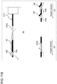
A seventh exemplary embodiment will be described with reference to FIG. 13. FIG. 13 is a view schematically showing a path of airflow near a phosphor wheel. In (a) of FIG. 13, a cross-section of the phosphor wheel taken along a radial direction is shown. In (b) of FIG. 13, there is shown a cross-section of a portion in which blade 33 f is provided taken along a circumferential direction.
In phosphor wheel 13 of the first exemplary embodiment, opening 13 c and blades 33 a and 33 b are provided on the inner circumferential side of phosphor layer 16 of phosphor wheel 13, and opening 13 d and blade 33 f are provided on the outer circumferential side of phosphor layer 16. On the other hand, in phosphor wheel 713 of the seventh exemplary embodiment, only opening 13 d and blade 33 f are provided on the outer circumferential side of phosphor layer 16.
According to the above-mentioned structure, blade 33 f having the same structure as in the first exemplary embodiment is rotated to draw the air, which flows on the first face side of phosphor wheel 713, to the second face side through opening 13 d. Note that, in the present exemplary embodiment, any openings are not provided on the inner circumferential side of phosphor layer 16, so that air can hardly be supplied to the first face side from the second face side. Therefore, in the case where air is supplied from a central upper part of the first face of phosphor wheel 713, the present exemplary embodiment is applicable suitably. Phosphor wheel 713 of the present exemplary embodiment can absorb the heat generated in phosphor layer 16, while reducing time and effort for forming the blades on the inner circumferential side.
Note that, it goes without saying that opening 13 d and blade 33 f described in the second to fourth exemplary embodiments are also applicable, even when only opening 13 d and blade 33 f are provided on the outer circumferential side of phosphor layer 16, like the seventh exemplary embodiment.
Eighth Exemplary Embodiment
1. Structure
An eighth exemplary embodiment 8 will be described with reference to FIGS. 14A through 14D. FIG. 14A is a perspective view showing a first face side of a phosphor wheel in the eight exemplary embodiment. FIG. 14B is a plan view showing the first face side of the phosphor wheel. FIG. 14C is a side view of the phosphor wheel. FIG. 14D is a cross-sectional view of the phosphor wheel taken along line 14D-14D of FIG. 14B.
In phosphor wheel 13 of the first exemplary embodiment, opening 13 c and blades 33 a and 33 b are provided on the inner circumferential side of phosphor layer 16 of phosphor wheel 13, and opening 13 d and blade 33 f are provided on the outer circumferential side of phosphor layer 16. On the other hand, in phosphor wheel 813 of the eighth exemplary embodiment, any openings are not provided on the outer circumferential side of phosphor layer 16, but only blade 833 f is provided at an edge portion on an outer circumferential side of phosphor wheel 813.
Specifically, substrate 813 a has a structure similar to that of FIG. 8F in the second exemplary embodiment, and has no openings on the outer circumferential side of phosphor layer 16, although having opening 13 ca on the inner circumferential side of phosphor layer 16.
Further, instead of disc-shaped member 33 in the first exemplary embodiment, dish-shaped member 833, which has a circular dish-like shape whose axis side is recessed with respect to its outer circumferential side, is employed as shown in FIGS. 14C and 14D. Annular opening 33 y is provided on a center side of dish-shaped member 833, and inclined portion 33 s with an annular slope is provided around annular opening 33 y. On an upper face of annular inclined portion 33 s, blades 33 x projecting upward (first face side) are provided at third predetermined angular intervals in a circumferential direction, as shown also in FIGS. 14A and 14B.
Further, as shown also in FIGS. 14A and 14B, outer circumferential portion 833 d of dish-shaped member 833 is inclined downward. On outer circumferential portion 833 d of dish-shaped member 833, blades 833 f projecting upward are provided at fourth predetermined angular intervals in the circumferential direction.
According to the above-mentioned structure, when phosphor wheel 813 rotates, blade 33 x is rotated to draw the air, which flows on the second face side of phosphor wheel 813, into a space between substrate 813 a and dish-shaped member 833 from opening 33 y of dish-shaped member 833. The drawn air rises up along inclined portion 33 s, and flows out to the first face side from opening 13 ca of substrate 813 a. In other words, an opening passing through phosphor wheel 813 between the first face and the second face is formed by opening 13 ca of substrate 813 a and opening 33 y of dish-shaped member 833. Herein, blade 33 x is formed to project to the first face side from dish-shaped member 833, but blade 33 x may be formed on substrate 813 a so as to project to the second face side from substrate 813 a.
The air flowing out to the first face side absorbs the heat generated in phosphor layer 16, when passing through above phosphor layer 16. Especially, in the present exemplary embodiment, the outer circumferential portion of dish-shaped member 833 is inclined to the second face side, and blades 833 f projecting upward are provided on the outer circumferential portion. Thus, the airflow passing through above phosphor layer 16 is attracted to the second face side during rotation of phosphor wheel 813, so that a path of the airflow is bent downward. Therefore, the heat generated in phosphor layer 16 is absorbed effectively, thereby making it possible to cool phosphor layer 16. In other words, outer circumferential portion 833 d of dish-shaped member 833 is a passage for sending air to the second face from the first face.
2. Effect
Phosphor wheel 813 in the present exemplary embodiment includes a first face that has phosphor layer 16, a second face on an opposite sided to the first face, and blade 833 f (first blade) provided to project from the first face. Blades 833 f is provided to send the air on the first face side to the second face side through the outer circumferential edge of the first face during rotation of phosphor wheel 13.
Thus, the heat generated in a fluorescent substance of phosphor layer 16 on the first face side can be dissipated to the second face side opposite to the first face side. Therefore, cooling performance of phosphor wheel 13 is improved.
Phosphor wheel 813 of the present exemplary embodiment further includes openings 13 ca and 33 y (second opening) provided to pass through between the first face and the second face, and blades 33 x (second blade) provided to project to the first face (one of the first face and the second face) side. Blade 33 x is provided to send the air on the second face side to the first face side through openings 13 ca and 33 y during rotation of phosphor wheel 813.
Thus, cooling air can be sent to the first face side on which phosphor layer 16, which generates heat, is provided. Therefore, cooling performance of phosphor wheel 13 is more improved.
In phosphor wheel 813 of the present exemplary embodiment, blade 833 f (first blade) is disposed on outer circumferential portion 833 d of the first face, which is located on the outer circumferential side of phosphor layer 16, and openings 13 ca and 33 y are disposed on the inner circumferential side of phosphor layer 16.
Thus, the cooling air, which is sent to the first face side through openings 13 ca and 33 yl, flows toward blades 833 f on the outer circumferential side automatically, due to centrifugal force caused by rotation of phosphor wheel 813. Therefore, cooling performance of phosphor wheel 13 is further improved.
Other Exemplary Embodiments
As mentioned above, one exemplary embodiment of the present disclosure has been described, but the present disclosure is not limited to the above-mentioned exemplary embodiment, and various modifications may be made without departing from the scope of the disclosure.
(A)
In the above-mentioned exemplary embodiment, a phosphor wheel is constituted by two members, i.e., a disc-shaped substrate and a disc-shaped member, or a disc-shaped substrate and a dish-shaped member having a disc shape. The phosphor wheel, however, may also be constituted by the above-mentioned each blade, each opening, and a single disc-shaped member with a phosphor layer.
(B)
In the above-mentioned exemplary embodiment, as shown in FIG. 5 or the like, it is illustrated, by example, that pressurization fan 15 is provided in a lower space of phosphor wheel 13, in order to cause the airflow generated by the blade provided in the phosphor wheel to circulate in casing unit 11 efficiently. The present disclosure, however, is not limited to this. For instance, a phosphor wheel device may not have a pressurization fan in a case unit, and a light conversion device using the same may be employed. In this case, the airflow generated by the blade provided on the phosphor wheel may be used to cool air containing the heat, which is generated in the phosphor layer, in a heat absorber.
To circulate the airflow passing through the inside of the heat absorber efficiently, however, only wind force caused by the blade may not be sufficient. Therefore, if fins of the heat absorber have a large pressure loss, for example, it will be preferred that pressurization fan 15 is provided to send air in the same direction as the airflow generated by the blade flows.
(C)
In the above-mentioned exemplary embodiment, as shown in FIG. 5 or the like, it is illustrated, by example, that updraft guide 11 e for raising up airflow is provided on an upper face of bottom portion 11 d, which corresponds to a lower space of phosphor wheel 13 in casing unit 11. The present disclosure, however, is not limited to this. For instance, a phosphor wheel device may not have an updraft guide, and a light conversion device using the same may be employed. In this case, only wind force caused by the blade is used to raise the airflow, which has passed through the heat absorber, along an axial direction. However, this may make it difficult to circulate the airflow sufficiently. Therefore, like the above-mentioned exemplary embodiment, pressurization fan 15 may be provided to send air in the same direction as the airflow generated by the blade flows. Thus, even if not providing an updraft guide, a sufficient circulation of airflow will be obtained in casing unit 11.
(D)
In the above-mentioned exemplary embodiment, as shown in FIG. 2 or the like, it is illustrated, by example, that the heat generated in phosphor layer 16 of the phosphor wheel is absorbed in heat absorber 21 through air, and then dissipated to the outside from heat dissipater 22 thermally connected to heat absorber 21 via heat pipe 24. The present disclosure, however, is not limited to this. For instance, an outer wall fin may be provided on an external face of the casing unit accommodating the phosphor wheel device and the light conversion device. The heat generated in the phosphor layer of the phosphor wheel may be dissipated to the outside through the outer wall fin. In other words, in addition to the heat dissipation function of the heat dissipater, the above-mentioned structure may also have a heat dissipation function from the outer wall fin, i.e., dissipate heat from the outer wall fin of the casing unit, so that the heat generated in a portion of the phosphor layer can be dissipated to the outside more efficiently.
(E)
In the above-mentioned exemplary embodiment, it is illustrated, by example, that the heat generated in phosphor layer 16 of the phosphor wheel is dissipated to the outside through heat absorber 21 and heat dissipater 22, which are thermally connected to each other via heat pipe 24. The present disclosure, however, is not limited to this. For instance, the heat absorber and the heat dissipater may directly be connected to each other to remove a heat pipe from the light conversion device. Even in this case, the heat absorber and the heat dissipater are formed to pass through a partition of the casing unit and thermally connected to each other. Therefore, the heat absorber and the heat dissipater can dissipate the heat, which is generated in the phosphor layer of the phosphor wheel, to the outside, while circulating it inside the casing unit using the blade.
(F)
In the above-mentioned exemplary embodiment, it is illustrated, by example, that the phosphor wheel and the light conversion device of the present disclosure are mounted on projector 100 of a three-chip DLP type including three DMDs 7. The present disclosure, however, is not limited to this. For instance, the phosphor wheel and light conversion device of the present disclosure may be mounted on a projector of a one-chip DLP type in which a single DMD and a color wheel are combined.
(G)
In the above-mentioned exemplary embodiment, it is illustrated, by example, that the phosphor wheel and light conversion device of the present disclosure are mounted on projector 100 of a DLP type. The present disclosure, however, is not limited to this. For instance, the phosphor wheel and the light conversion device of the present disclosure may be mounted on a liquid crystal type of projector using LCD (Liquid Crystal Display) or LCOS (Liquid Crystal on Silicon).
(H)
In the above-mentioned exemplary embodiment, as the projection display apparatus in accordance with the present disclosure, projector 100 is illustrated, by example. The present disclosure, however, is not limited to this. For instance, the present disclosure may be applied to other projection display apparatuses, such as a rear projection television, other than projector 100.
INDUSTRIAL APPLICABILITY
The phosphor wheel of the present disclosure has an effect in which a cooling effect is more improved than before, and thus is widely available in a phosphor wheel device equipped with a phosphor wheel of which the heat generated in a fluorescent substance is enlarged due to an increase in brightness, a light conversion device, and a projection display apparatus.

Claims (14)

What is claimed is:
1. A phosphor wheel comprising:
a first face that has a phosphor layer;
a second face located on an opposite side to the first face;
a first blade provided to project from one of the first face and the second face; and
a passage that sends air to the second face from the first face,
wherein
the first blade is provided to send air on a side of the first face to a side of the second face through the passage during rotation of the phosphor wheel,
the passage is a first opening provided to pass through the phosphor wheel between the first face and the second face,
the phosphor wheel further comprises:
a second opening provided to pass through the phosphor wheel between the first face and the second face; and
a second blade provided to project from one of the first face and the second face, and
the second blade is provided to send air on the side of the second face to the side of the first face through the second opening during rotation of the phosphor wheel.
2. The phosphor wheel according to claim 1, wherein
the first blade is provided to draw air on the side of the second face into the side of the first face through the second opening, and send the drawn air to the side of the second face through the first opening during rotation of the phosphor wheel.
3. The phosphor wheel according to claim 1, wherein
the phosphor layer has an annular shape centered on a rotation axis of the phosphor wheel, and
the first opening and the second opening are disposed to sandwich the phosphor layer in a radial direction of the phosphor wheel.
4. The phosphor wheel according to claim 2, wherein
the phosphor layer has an annular shape centered on a rotation axis of the phosphor wheel, and
the first opening and the second opening are disposed to sandwich the phosphor layer in a radial direction of the phosphor wheel.
5. The phosphor wheel according to claim 3, wherein
the first opening is disposed on an outer circumferential side of the phosphor layer, and
the second opening is disposed on an inner circumferential side of the phosphor layer.
6. The phosphor wheel according to claim 4, wherein
the first opening is disposed on an outer circumferential side of the phosphor layer, and
the second opening is disposed on an inner circumferential side of the phosphor layer.
7. The phosphor wheel according to claim 1, wherein
the passage is an outer circumferential portion of the first face inclined to toward the second face, and
the first blade is provided to project from the first face.
8. The phosphor wheel according to claim 7, wherein
the first blade is disposed in the outer circumferential portion of the first face on an outer circumferential side of the phosphor layer, and
the second opening is disposed on an inner circumferential side of the phosphor layer.
9. A phosphor wheel device comprising:
the phosphor wheel according to claim 1;
a motor that drives the phosphor wheel to rotate; and
a casing unit in which a circulation path of airflow generated by the first blade is formed, the casing unit accommodating the phosphor wheel and the motor.
10. A light conversion device comprising:
the phosphor wheel device according to claim 9;
a heat absorber that absorbs heat generated near the phosphor layer of the phosphor wheel;
a heat dissipater that is thermally connected to the heat absorber and dissipates the heat of the airflow to an outside of the casing unit; and
an optical lens that is attached to an opening portion formed in the casing unit and converges light emitted from a fluorescent substance of the phosphor layer, while passing excitation light that excites the fluorescent substance of the phosphor layer.
11. The light conversion device according to claim 10, wherein
the first blade is disposed close to the optical lens so as to face the optical lens.
12. A projection display apparatus comprising:
the light conversion device according to claim 10;
a light source that emits the excitation light that excites the fluorescent substance of the phosphor layer;
a display element that forms a projection image using the light emitted from the light source; and
an optical component that optically connects the light source, the light conversion device, and the display element.
13. A phosphor wheel comprising:
a first face that has a phosphor layer;
a second face located on an opposite side to the first face;
a first blade provided to project from one of the first face and the second face; and
a passage that sends air to the second face from the first face,
wherein
the first blade is provided to send air on a side of the first face to a side of the second face through the passage during rotation of the phosphor wheel,
the passage is a first opening provided to pass through the phosphor wheel between the first face and the second face,
the phosphor wheel further comprises a second opening provided to pass through the phosphor wheel between the first face and the second face, and
the first blade is provided to draw air on the side of the second face into the side of the first face through the second opening, and send the drawn air to the side of the second face through the first opening during rotation of the phosphor wheel.
14. A phosphor wheel comprising:
a first face that has a phosphor layer;
a second face located on an opposite side to the first face;
a first blade provided to project from one of the first face and the second face; and
a passage that sends air to the second face from the first face,
wherein
the first blade is provided to send air on a side of the first face to a side of the second face through the passage during rotation of the phosphor wheel,
the passage is an outer circumferential portion of the first face inclined to toward the second face,
the first blade is provided to project from the first face,
the phosphor wheel further comprises:
a second opening provided to pass through the phosphor wheel between the first face and the second face; and
a second blade provided to project to one of the first face and the second face, and
the second blade is provided to send air on the side of the second face to the side of the first face through the second opening during rotation of the phosphor wheel.
US16/129,886 2017-09-25 2018-09-13 Phosphor wheel, phosphor wheel device including the same, light conversion device, and projection display apparatus Active US10520800B2 (en)

Applications Claiming Priority (4)

Application Number Priority Date Filing Date Title
JP2017184022 2017-09-25
JP2017-184022 2017-09-25
JP2018-169852 2018-09-11
JP2018169852A JP7145434B2 (en) 2017-09-25 2018-09-11 Phosphor wheel, phosphor wheel device provided with same, light conversion device, projection display device

Publications (2)

Publication Number Publication Date
US20190094671A1 US20190094671A1 (en) 2019-03-28
US10520800B2 true US10520800B2 (en) 2019-12-31

Family

ID=65808948

Family Applications (1)

Application Number Title Priority Date Filing Date
US16/129,886 Active US10520800B2 (en) 2017-09-25 2018-09-13 Phosphor wheel, phosphor wheel device including the same, light conversion device, and projection display apparatus

Country Status (1)

Country Link
US (1) US10520800B2 (en)

Cited By (5)

* Cited by examiner, † Cited by third party
Publication number Priority date Publication date Assignee Title
US11048154B2 (en) * 2019-03-29 2021-06-29 Qisda Corporation Light source module and projector with fan and driver
US20220260241A1 (en) * 2019-07-26 2022-08-18 Panasonic Intellectual Property Management Co., Ltd. Phosphor wheel
US11624889B2 (en) 2021-06-18 2023-04-11 Delta Electronics, Inc. Fluorescent color wheel
TWI799897B (en) * 2021-06-18 2023-04-21 台達電子工業股份有限公司 Fluorescent color wheel
TWI836311B (en) * 2021-01-26 2024-03-21 日商松下知識產權經營股份有限公司 glow wheel

Families Citing this family (9)

* Cited by examiner, † Cited by third party
Publication number Priority date Publication date Assignee Title
CN109031869B (en) * 2018-08-07 2021-04-20 苏州佳世达光电有限公司 Projection device and wavelength conversion module thereof
CN113934090B (en) * 2019-01-23 2023-05-12 中强光电股份有限公司 Radiating module and projection device
EP3835866A1 (en) * 2019-12-10 2021-06-16 Barco A laser reflection unit
CN114077136B (en) 2020-08-20 2024-03-08 台达电子工业股份有限公司 Wavelength conversion element and light source module
TWI845746B (en) * 2020-08-20 2024-06-21 台達電子工業股份有限公司 Wavelength conversion member and light source module
CN114967303B (en) * 2021-02-26 2024-08-27 中强光电股份有限公司 Wavelength conversion device, manufacturing method thereof and projector
JP2022185236A (en) * 2021-06-02 2022-12-14 セイコーエプソン株式会社 Wavelength conversion device, light source device and projector
CN214795550U (en) * 2021-06-25 2021-11-19 中强光电股份有限公司 Wavelength conversion element and projection device
TWI820817B (en) * 2022-07-25 2023-11-01 國立中山大學 Conjugate cam reducer

Citations (8)

* Cited by examiner, † Cited by third party
Publication number Priority date Publication date Assignee Title
US20130169938A1 (en) * 2011-12-29 2013-07-04 Hon Hai Precision Industry Co., Ltd. Color wheel with fan blade
US20160077326A1 (en) * 2014-09-17 2016-03-17 Panasonic Intellectual Property Management Co., Ltd. Phosphor wheel device, phosphor wheel device accommodating housing and projection-type image display device
JP2016053608A (en) 2014-09-03 2016-04-14 Zero Lab株式会社 Phosphor wheel and illumination optical system
WO2017098705A1 (en) 2015-12-10 2017-06-15 パナソニックIpマネジメント株式会社 Fluorescent substance wheel device, light conversion device provided with same, and projection display device
US20170192346A1 (en) * 2016-01-06 2017-07-06 Panasonic Intellectual Property Management Co., Ltd. Cooling device and projection-type image display apparatus
US9915418B2 (en) * 2015-12-22 2018-03-13 Panasonic Intellectual Property Management Co., Ltd. Phosphor wheel, illumination apparatus and projection type image display apparatus
US9983467B2 (en) * 2016-03-08 2018-05-29 Panasonic Intellectual Property Management Co., Ltd. Phosphor wheel and projection-type image display device
US20190146314A1 (en) * 2017-11-14 2019-05-16 Panasonic Intellectual Property Management Co., Ltd. Phosphor wheel and light conversion device including the same

Patent Citations (9)

* Cited by examiner, † Cited by third party
Publication number Priority date Publication date Assignee Title
US20130169938A1 (en) * 2011-12-29 2013-07-04 Hon Hai Precision Industry Co., Ltd. Color wheel with fan blade
JP2016053608A (en) 2014-09-03 2016-04-14 Zero Lab株式会社 Phosphor wheel and illumination optical system
US20160077326A1 (en) * 2014-09-17 2016-03-17 Panasonic Intellectual Property Management Co., Ltd. Phosphor wheel device, phosphor wheel device accommodating housing and projection-type image display device
WO2017098705A1 (en) 2015-12-10 2017-06-15 パナソニックIpマネジメント株式会社 Fluorescent substance wheel device, light conversion device provided with same, and projection display device
US20180224731A1 (en) 2015-12-10 2018-08-09 Panasonic Intellectual Property Management Co., Ltd. Fluorescent substance wheel device, light conversion device provided with same, and projection display apparatus
US9915418B2 (en) * 2015-12-22 2018-03-13 Panasonic Intellectual Property Management Co., Ltd. Phosphor wheel, illumination apparatus and projection type image display apparatus
US20170192346A1 (en) * 2016-01-06 2017-07-06 Panasonic Intellectual Property Management Co., Ltd. Cooling device and projection-type image display apparatus
US9983467B2 (en) * 2016-03-08 2018-05-29 Panasonic Intellectual Property Management Co., Ltd. Phosphor wheel and projection-type image display device
US20190146314A1 (en) * 2017-11-14 2019-05-16 Panasonic Intellectual Property Management Co., Ltd. Phosphor wheel and light conversion device including the same

Cited By (6)

* Cited by examiner, † Cited by third party
Publication number Priority date Publication date Assignee Title
US11048154B2 (en) * 2019-03-29 2021-06-29 Qisda Corporation Light source module and projector with fan and driver
US20220260241A1 (en) * 2019-07-26 2022-08-18 Panasonic Intellectual Property Management Co., Ltd. Phosphor wheel
US11966151B2 (en) * 2019-07-26 2024-04-23 Panasonic Intellectual Property Management Co., Ltd. Phosphor wheel
TWI836311B (en) * 2021-01-26 2024-03-21 日商松下知識產權經營股份有限公司 glow wheel
US11624889B2 (en) 2021-06-18 2023-04-11 Delta Electronics, Inc. Fluorescent color wheel
TWI799897B (en) * 2021-06-18 2023-04-21 台達電子工業股份有限公司 Fluorescent color wheel

Also Published As

Publication number Publication date
US20190094671A1 (en) 2019-03-28

Similar Documents

Publication Publication Date Title
US10520800B2 (en) Phosphor wheel, phosphor wheel device including the same, light conversion device, and projection display apparatus
JP6979572B2 (en) Phosphor wheel and phosphor wheel device equipped with it, light conversion device, projection type display device
US10527840B2 (en) Light conversion device and projection display apparatus including same
US10156780B2 (en) Fluorescent substance wheel device, light conversion device provided with same, and projection display apparatus
US10809604B2 (en) Phosphor wheel and light conversion device including the same
JP5804130B2 (en) Light source device and projector
US9442352B2 (en) Light source device including passage forming member and image projecting apparatus having the same
JP5527059B2 (en) Light source device and projector
JP6206989B2 (en) Cooling structure, illumination optical system, projection display device, and cooling method
JP6745486B2 (en) Phosphor wheel and projection type image display device
JP7145434B2 (en) Phosphor wheel, phosphor wheel device provided with same, light conversion device, projection display device
CN108541297B (en) Light conversion device, light source device, and projection display device
JP2022126696A (en) Light source device and projection-type picture display device
JP2016200656A (en) projector
JP7030473B2 (en) A light source device and a projection type display device having this
JP6207000B2 (en) Cooling structure, illumination optical system, projection display device, and cooling method
JP6206999B2 (en) Cooling structure, illumination optical system, projection display device, and cooling method
JP6885423B2 (en) A light source device and an image projection device having this light source device
JP6662534B2 (en) Cooling structure of illumination optical system and projection display device
JP6468615B2 (en) Cooling structure of illumination optical system and projection display device
JP2019003096A (en) Phosphor wheel, light source device, and projector

Legal Events

Date Code Title Description
FEPP Fee payment procedure

Free format text: ENTITY STATUS SET TO UNDISCOUNTED (ORIGINAL EVENT CODE: BIG.); ENTITY STATUS OF PATENT OWNER: LARGE ENTITY

STPP Information on status: patent application and granting procedure in general

Free format text: DOCKETED NEW CASE - READY FOR EXAMINATION

AS Assignment

Owner name: PANASONIC INTELLECTUAL PROPERTY MANAGEMENT CO., LT

Free format text: ASSIGNMENT OF ASSIGNORS INTEREST;ASSIGNOR:IKEO, KENJI;REEL/FRAME:048245/0146

Effective date: 20180905

STPP Information on status: patent application and granting procedure in general

Free format text: NON FINAL ACTION MAILED

STPP Information on status: patent application and granting procedure in general

Free format text: NOTICE OF ALLOWANCE MAILED -- APPLICATION RECEIVED IN OFFICE OF PUBLICATIONS

STPP Information on status: patent application and granting procedure in general

Free format text: PUBLICATIONS -- ISSUE FEE PAYMENT VERIFIED

STCF Information on status: patent grant

Free format text: PATENTED CASE

MAFP Maintenance fee payment

Free format text: PAYMENT OF MAINTENANCE FEE, 4TH YEAR, LARGE ENTITY (ORIGINAL EVENT CODE: M1551); ENTITY STATUS OF PATENT OWNER: LARGE ENTITY

Year of fee payment: 4