JP6589534B2 - Wavelength conversion device, illumination device, and projector - Google Patents
Wavelength conversion device, illumination device, and projector Download PDFInfo
- Publication number
- JP6589534B2 JP6589534B2 JP2015198266A JP2015198266A JP6589534B2 JP 6589534 B2 JP6589534 B2 JP 6589534B2 JP 2015198266 A JP2015198266 A JP 2015198266A JP 2015198266 A JP2015198266 A JP 2015198266A JP 6589534 B2 JP6589534 B2 JP 6589534B2
- Authority
- JP
- Japan
- Prior art keywords
- light
- wavelength conversion
- wavelength
- conversion element
- opening
- Prior art date
- Legal status (The legal status is an assumption and is not a legal conclusion. Google has not performed a legal analysis and makes no representation as to the accuracy of the status listed.)
- Active
Links
Images


Classifications
-
- G—PHYSICS
- G03—PHOTOGRAPHY; CINEMATOGRAPHY; ANALOGOUS TECHNIQUES USING WAVES OTHER THAN OPTICAL WAVES; ELECTROGRAPHY; HOLOGRAPHY
- G03B—APPARATUS OR ARRANGEMENTS FOR TAKING PHOTOGRAPHS OR FOR PROJECTING OR VIEWING THEM; APPARATUS OR ARRANGEMENTS EMPLOYING ANALOGOUS TECHNIQUES USING WAVES OTHER THAN OPTICAL WAVES; ACCESSORIES THEREFOR
- G03B21/00—Projectors or projection-type viewers; Accessories therefor
- G03B21/14—Details
- G03B21/16—Cooling; Preventing overheating
-
- F—MECHANICAL ENGINEERING; LIGHTING; HEATING; WEAPONS; BLASTING
- F21—LIGHTING
- F21V—FUNCTIONAL FEATURES OR DETAILS OF LIGHTING DEVICES OR SYSTEMS THEREOF; STRUCTURAL COMBINATIONS OF LIGHTING DEVICES WITH OTHER ARTICLES, NOT OTHERWISE PROVIDED FOR
- F21V29/00—Protecting lighting devices from thermal damage; Cooling or heating arrangements specially adapted for lighting devices or systems
- F21V29/50—Cooling arrangements
- F21V29/502—Cooling arrangements characterised by the adaptation for cooling of specific components
-
- F—MECHANICAL ENGINEERING; LIGHTING; HEATING; WEAPONS; BLASTING
- F21—LIGHTING
- F21V—FUNCTIONAL FEATURES OR DETAILS OF LIGHTING DEVICES OR SYSTEMS THEREOF; STRUCTURAL COMBINATIONS OF LIGHTING DEVICES WITH OTHER ARTICLES, NOT OTHERWISE PROVIDED FOR
- F21V29/00—Protecting lighting devices from thermal damage; Cooling or heating arrangements specially adapted for lighting devices or systems
- F21V29/50—Cooling arrangements
- F21V29/70—Cooling arrangements characterised by passive heat-dissipating elements, e.g. heat-sinks
- F21V29/74—Cooling arrangements characterised by passive heat-dissipating elements, e.g. heat-sinks with fins or blades
- F21V29/78—Cooling arrangements characterised by passive heat-dissipating elements, e.g. heat-sinks with fins or blades with helically or spirally arranged fins or blades
-
- F—MECHANICAL ENGINEERING; LIGHTING; HEATING; WEAPONS; BLASTING
- F21—LIGHTING
- F21V—FUNCTIONAL FEATURES OR DETAILS OF LIGHTING DEVICES OR SYSTEMS THEREOF; STRUCTURAL COMBINATIONS OF LIGHTING DEVICES WITH OTHER ARTICLES, NOT OTHERWISE PROVIDED FOR
- F21V29/00—Protecting lighting devices from thermal damage; Cooling or heating arrangements specially adapted for lighting devices or systems
- F21V29/50—Cooling arrangements
- F21V29/70—Cooling arrangements characterised by passive heat-dissipating elements, e.g. heat-sinks
- F21V29/83—Cooling arrangements characterised by passive heat-dissipating elements, e.g. heat-sinks the elements having apertures, ducts or channels, e.g. heat radiation holes
-
- F—MECHANICAL ENGINEERING; LIGHTING; HEATING; WEAPONS; BLASTING
- F21—LIGHTING
- F21V—FUNCTIONAL FEATURES OR DETAILS OF LIGHTING DEVICES OR SYSTEMS THEREOF; STRUCTURAL COMBINATIONS OF LIGHTING DEVICES WITH OTHER ARTICLES, NOT OTHERWISE PROVIDED FOR
- F21V9/00—Elements for modifying spectral properties, polarisation or intensity of the light emitted, e.g. filters
- F21V9/30—Elements containing photoluminescent material distinct from or spaced from the light source
-
- G—PHYSICS
- G02—OPTICS
- G02B—OPTICAL ELEMENTS, SYSTEMS OR APPARATUS
- G02B26/00—Optical devices or arrangements for the control of light using movable or deformable optical elements
- G02B26/007—Optical devices or arrangements for the control of light using movable or deformable optical elements the movable or deformable optical element controlling the colour, i.e. a spectral characteristic, of the light
- G02B26/008—Optical devices or arrangements for the control of light using movable or deformable optical elements the movable or deformable optical element controlling the colour, i.e. a spectral characteristic, of the light in the form of devices for effecting sequential colour changes, e.g. colour wheels
-
- G—PHYSICS
- G02—OPTICS
- G02B—OPTICAL ELEMENTS, SYSTEMS OR APPARATUS
- G02B7/00—Mountings, adjusting means, or light-tight connections, for optical elements
- G02B7/008—Mountings, adjusting means, or light-tight connections, for optical elements with means for compensating for changes in temperature or for controlling the temperature; thermal stabilisation
-
- G—PHYSICS
- G03—PHOTOGRAPHY; CINEMATOGRAPHY; ANALOGOUS TECHNIQUES USING WAVES OTHER THAN OPTICAL WAVES; ELECTROGRAPHY; HOLOGRAPHY
- G03B—APPARATUS OR ARRANGEMENTS FOR TAKING PHOTOGRAPHS OR FOR PROJECTING OR VIEWING THEM; APPARATUS OR ARRANGEMENTS EMPLOYING ANALOGOUS TECHNIQUES USING WAVES OTHER THAN OPTICAL WAVES; ACCESSORIES THEREFOR
- G03B21/00—Projectors or projection-type viewers; Accessories therefor
- G03B21/14—Details
- G03B21/20—Lamp housings
- G03B21/2006—Lamp housings characterised by the light source
- G03B21/2033—LED or laser light sources
- G03B21/204—LED or laser light sources using secondary light emission, e.g. luminescence or fluorescence
-
- F—MECHANICAL ENGINEERING; LIGHTING; HEATING; WEAPONS; BLASTING
- F21—LIGHTING
- F21Y—INDEXING SCHEME ASSOCIATED WITH SUBCLASSES F21K, F21L, F21S and F21V, RELATING TO THE FORM OR THE KIND OF THE LIGHT SOURCES OR OF THE COLOUR OF THE LIGHT EMITTED
- F21Y2115/00—Light-generating elements of semiconductor light sources
- F21Y2115/30—Semiconductor lasers
-
- G—PHYSICS
- G02—OPTICS
- G02B—OPTICAL ELEMENTS, SYSTEMS OR APPARATUS
- G02B27/00—Optical systems or apparatus not provided for by any of the groups G02B1/00 - G02B26/00, G02B30/00
- G02B27/10—Beam splitting or combining systems
- G02B27/14—Beam splitting or combining systems operating by reflection only
- G02B27/149—Beam splitting or combining systems operating by reflection only using crossed beamsplitting surfaces, e.g. cross-dichroic cubes or X-cubes
Landscapes
- Physics & Mathematics (AREA)
- General Physics & Mathematics (AREA)
- Engineering & Computer Science (AREA)
- Optics & Photonics (AREA)
- General Engineering & Computer Science (AREA)
- Spectroscopy & Molecular Physics (AREA)
- Astronomy & Astrophysics (AREA)
- Multimedia (AREA)
- Projection Apparatus (AREA)
- Non-Portable Lighting Devices Or Systems Thereof (AREA)
- Transforming Electric Information Into Light Information (AREA)
Description
本発明は、波長変換装置、照明装置およびプロジェクターに関する。 The present invention relates to a wavelength conversion device, an illumination device, and a projector.
近年、プロジェクター用の照明装置として、蛍光体が用いられている。 In recent years, phosphors have been used as illumination devices for projectors.
下記特許文献1の照明装置では、蛍光体を支持する基材の裏面に冷却フィンが設けられている。基材と冷却フィンは、一体に形成されている。
In the illuminating device of the following
ところで、基材の蛍光体を支持する面は、蛍光体への励起光を受けて温度が高くなり易い。上記従来技術では、蛍光体を支持する基材の裏面に設けられた冷却フィンに熱を伝熱させ、間接的に蛍光体を冷却していたため、蛍光体の冷却が不十分になる場合がある。 By the way, the surface of the substrate that supports the phosphor is likely to be heated by receiving excitation light to the phosphor. In the above prior art, since the phosphor is indirectly cooled by transferring heat to the cooling fin provided on the back surface of the base material supporting the phosphor, the phosphor may be insufficiently cooled. .
本発明はこのような事情に鑑みてなされたものであって、蛍光体を十分に冷却することができる、波長変換装置、照明装置およびプロジェクターを提供することを目的とする。 The present invention has been made in view of such circumstances, and an object thereof is to provide a wavelength conversion device, an illumination device, and a projector that can sufficiently cool a phosphor.
本発明の第1態様に従えば、回転装置と、前記回転装置により回転する基材と、前記基材の第1の面に設けられた波長変換素子及び複数のフィンと、を備え、前記第1の面は、前記波長変換素子を冷却する空気を導入する空気導入流路の開口部と対向して設けられている、波長変換装置が提供される。 According to the first aspect of the present invention, the rotating device, the base material rotated by the rotating device, a wavelength conversion element and a plurality of fins provided on the first surface of the base material, The surface of 1 is provided with a wavelength conversion device provided to face an opening of an air introduction flow channel for introducing air for cooling the wavelength conversion element.
第1態様に係る波長変換装置によれば、回転装置により基材が回転すると、基材の第1の面に設けられた複数のフィンが回転し、第1の面に対向する空気導入流路の開口部から導入された空気が第1の面に沿って流れ、第1の面に設けられた波長変換素子を直接的に冷却する。このように、波長変換素子と複数のフィンを同じ第1の面に設け、第1の面に空気導入流路の開口部を対向させることで、波長変換素子の表面に積極的に空気を流すことができ、波長変換素子を十分に冷却することができる。 According to the wavelength conversion device according to the first aspect, when the substrate is rotated by the rotating device, the plurality of fins provided on the first surface of the substrate rotate and the air introduction channel facing the first surface. The air introduced from the opening of the first gas flows along the first surface, and directly cools the wavelength conversion element provided on the first surface. In this way, the wavelength conversion element and the plurality of fins are provided on the same first surface, and the opening of the air introduction flow channel is opposed to the first surface, so that air is actively flowed to the surface of the wavelength conversion element. And the wavelength conversion element can be sufficiently cooled.
また、上記第1態様において、前記開口部の少なくとも一部は、前記波長変換素子よりも前記回転装置の回転中心側に設けられている、という構成を採用する。
この構成によれば、波長変換素子よりも回転装置の回転中心側に空気が導入される。複数のフィンが回転すると、遠心力によって、基材の回転中心側から外周側に空気の流れが誘起されるため、この空気の流れに乗って、波長変換素子の表面を通過して外周に流れる空気の流量を増やすことができ、波長変換素子を十分に冷却することができる。
In the first aspect, a configuration is adopted in which at least a part of the opening is provided closer to the rotation center of the rotation device than the wavelength conversion element.
According to this configuration, air is introduced closer to the rotation center side of the rotation device than the wavelength conversion element. When a plurality of fins rotate, an air flow is induced from the rotation center side to the outer peripheral side of the substrate by centrifugal force, so it rides on the air flow and flows through the surface of the wavelength conversion element to the outer periphery. The flow rate of air can be increased, and the wavelength conversion element can be sufficiently cooled.
また、上記第1態様において、前記波長変換素子は、前記複数のフィンよりも前記回転中心側に設けられている、という構成を採用する。
この構成によれば、波長変換素子が複数のフィンよりも回転中心側に設けられているため、複数のフィンの設置スペースを広く確保でき、空気の流れの流量を増やすことができる。
Moreover, the said 1st aspect WHEREIN: The structure that the said wavelength conversion element is provided in the said rotation center side rather than the said several fin is employ | adopted.
According to this configuration, since the wavelength conversion element is provided closer to the rotation center than the plurality of fins, a wide installation space for the plurality of fins can be secured, and the flow rate of the air flow can be increased.
また、上記第1態様において、前記複数のフィンは、前記波長変換素子よりも前記回転中心側に設けられている、という構成を採用する。
この構成によれば、複数のフィンが波長変換素子よりも回転中心側に設けられているため、複数のフィンを小型にし、部品コストを下げることができる。
Moreover, the said 1st aspect employ | adopts the structure that the said several fin is provided in the said rotation center side rather than the said wavelength conversion element.
According to this configuration, since the plurality of fins are provided closer to the rotation center than the wavelength conversion element, the plurality of fins can be reduced in size and the component cost can be reduced.
本発明の第2態様に従えば、第1の波長帯の光を射出する光源と、前記第1の波長帯の前記光を受けて第2の波長帯の光を射出する、上記第1態様に係る波長変換装置と、を備える照明装置が提供される。 According to the second aspect of the present invention, the light source that emits the light in the first wavelength band and the first aspect that receives the light in the first wavelength band and emits the light in the second wavelength band. A wavelength conversion device according to the above is provided.
第2態様に係る照明装置は、上記第1態様に係る波長変換装置を備えるので、波長変換素子を十分に冷却することができ、明るい照明光を生成することができる。 Since the illumination device according to the second aspect includes the wavelength conversion device according to the first aspect, the wavelength conversion element can be sufficiently cooled, and bright illumination light can be generated.
また、上記第2態様において、前記第1の波長帯の光及び前記第2の波長帯の光の少なくともいずれか一方を導く光学部品と、前記光学部品を収容する光学部品用筐体と、前記光学部品用筐体に設けられ、前記第1の面に対し所定の距離をあけて対向する壁部と、を有する、という構成を採用する。
この構成によれば、光学部品を収容する光学部品用筐体に設けられた壁部が、第1の面に対し所定の距離をあけて対向するため、第1の面との間に流路が形成され、空気導入流路の開口部から導入された空気が第1の面に沿って流れ易くなる。これにより、第1の面における熱交換によって温まった空気の滞留や循環流れが減り、空気導入流路から導入される温度の低い空気の流量が増加するため、波長変換素子を十分に冷却することができる。
Further, in the second aspect, an optical component that guides at least one of the light in the first wavelength band and the light in the second wavelength band, an optical component housing that houses the optical component, A configuration is adopted in which a wall portion provided in the optical component casing and facing the first surface with a predetermined distance is provided.
According to this configuration, since the wall portion provided in the optical component housing that accommodates the optical component is opposed to the first surface with a predetermined distance, a flow path is formed between the first surface and the first surface. The air introduced from the opening of the air introduction flow path becomes easy to flow along the first surface. This reduces the stagnation and circulation flow of air heated by heat exchange on the first surface, and increases the flow rate of low-temperature air introduced from the air introduction flow path, so that the wavelength conversion element is sufficiently cooled. Can do.
また、上記第2態様において、前記壁部の少なくとも一部は、前記光学部品用筐体と一体で形成されている、という構成を採用する。
この構成によれば、壁部の少なくとも一部が光学部品用筐体と一体で形成されているため、部品点数を減らすことができる。
Moreover, in the said 2nd aspect, the structure that at least one part of the said wall part is integrally formed with the said housing | casing for optical components is employ | adopted.
According to this configuration, since at least a part of the wall portion is formed integrally with the optical component casing, the number of components can be reduced.
また、上記第2態様において、前記空気導入流路は、前記壁部を貫通して設けられている、という構成を採用する。
この構成によれば、第1の面と壁部との間に形成される流路に、温度の低い空気を直接導入することができ、波長変換素子を十分に冷却することができる。
Moreover, the said 2nd aspect WHEREIN: The structure that the said air introduction flow path is provided penetrating the said wall part is employ | adopted.
According to this configuration, air having a low temperature can be directly introduced into the flow path formed between the first surface and the wall portion, and the wavelength conversion element can be sufficiently cooled.
本発明の第3態様に従えば、上記第2態様に係る照明装置と、前記照明装置からの照明光を画像情報に応じて変調することにより画像光を形成する光変調装置と、前記画像光を投写する投写光学系と、を備えるプロジェクターが提供される。 According to a third aspect of the present invention, the illumination device according to the second aspect, a light modulation device that forms image light by modulating illumination light from the illumination device according to image information, and the image light And a projection optical system for projecting the projector.
第3態様に係るプロジェクターは、上記第2態様に係る照明装置を備えるので、波長変換素子を十分に冷却することができ、明るく画像品質に優れた表示を行うことができる。 Since the projector according to the third aspect includes the illumination device according to the second aspect, the wavelength conversion element can be sufficiently cooled, and a bright display with excellent image quality can be performed.
以下、本発明の実施の形態について、図面を参照して詳細に説明する。
なお、以下の説明で用いる図面は、特徴をわかりやすくするために、便宜上特徴となる部分を拡大して示している場合があり、各構成要素の寸法比率などが実際と同じであるとは限らない。
Hereinafter, embodiments of the present invention will be described in detail with reference to the drawings.
In addition, in the drawings used in the following description, in order to make the features easy to understand, there are cases where the portions that become the features are enlarged for the sake of convenience, and the dimensional ratios of the respective components are not always the same as the actual ones. Absent.
本実施形態に係るプロジェクターの一例について説明する。本実施形態のプロジェクター1は、スクリーンSCR(被投写面)上にカラー映像を表示する投写型画像表示装置である。
An example of the projector according to the present embodiment will be described. The
図1は、本実施形態に係るプロジェクター1の光学系を示す上面図である。
プロジェクター1は、図1に示すように、第1照明装置100(照明装置)、第2照明装置102、色分離導光光学系200、赤色光、緑色光、青色光の各色光に対応した液晶光変調装置400R,400G,400B(光変調装置)、クロスダイクロイックプリズム500及び投写光学系600を備える。
FIG. 1 is a top view showing an optical system of a
As shown in FIG. 1, the
第1照明装置100は、第1光源10(光源)、コリメート光学系70、ダイクロイックミラー80(光学部品)、コリメート集光光学系90(光学部品)、回転蛍光板30(波長変換装置)、第1レンズアレイ120、第2レンズアレイ130、偏光変換素子140及び重畳レンズ150を備える。
The
第1光源10は、励起光としてレーザー光からなる第1の波長帯の青色光(発光強度のピーク:約445nm)Eを射出する半導体レーザー(発光素子)からなる。第1光源10は、1つの半導体レーザーからなるものであってもよいし、多数の半導体レーザーからなるものであってもよい。
なお、第1光源10は、445nm以外の波長(例えば、460nm)の青色光を射出する半導体レーザーを用いることもできる。
The
The
本実施形態において、第1光源10は、光軸が照明光軸100axと直交するように配置されている。
コリメート光学系70は、第1レンズ72と、第2レンズ74とを備え、第1光源10からの光を略平行化する。第1レンズ72、第2レンズ74は、凸レンズからなる。
In the present embodiment, the
The collimating
ダイクロイックミラー80は、コリメート光学系70からコリメート集光光学系90までの光路中に、第1光源10の光軸及び照明光軸100axのそれぞれに対して45°の角度で交わるように配置されている。ダイクロイックミラー80は、青色光を反射し、赤色光及び緑色光を含む黄色の蛍光を通過させる。
The
コリメート集光光学系90は、ダイクロイックミラー80からの青色光Eを略集光した状態で回転蛍光板30の蛍光体層42に入射させる機能と、回転蛍光板30から射出される蛍光を略平行化する機能とを有する。コリメート集光光学系90は、第1レンズ92、第2レンズ93、及び第3レンズ94を備える。第1レンズ92、第2レンズ93、及び第3レンズ94は、凸レンズからなる。
The collimator condensing
回転蛍光板30は、モーター50(回転装置)と、円板40(基材)と、反射膜41(反射部材)と、蛍光体層(波長変換素子)42と、ヒートシンク51と、を備える。蛍光体層42は、第1光源10からの第1の波長の青色光Eによって励起されて第2の波長帯の蛍光Yを射出する。蛍光体層42の青色光Eが入射する面は、蛍光Yが射出される射出面でもある。蛍光Yは、赤色光及び緑色光を含む黄色の光である。
The rotating
第2照明装置102は、第2光源710、集光光学系760、散乱板732及びコリメート光学系770と、を備える。
The
第2光源710は、第1照明装置100の第1光源10と同一の半導体レーザーから構成される。
集光光学系760は、第1レンズ762及び第2レンズ764を備える。集光光学系760は、第2光源710からの青色光を散乱板732付近に集光する。第1レンズ762及び第2レンズ764は、凸レンズからなる。
The second
The condensing
散乱板732は、第2光源710からの青色光Bを散乱し、回転蛍光板30から射出される蛍光Yの配光分布に似た配光分布を有する青色光Bとする。散乱板732としては、例えば、光学ガラスからなる磨りガラスを用いることができる。
The
コリメート光学系770は、第1レンズ772と、第2レンズ774とを備え、散乱板732からの光を略平行化する。第1レンズ772及び第2レンズ774は、凸レンズからなる。
The collimating
本実施形態において、第2照明装置102からの青色光Bはダイクロイックミラー80で反射され、回転蛍光板30から射出されダイクロイックミラー80を透過した蛍光Yと合成されて白色光Wとなる。当該白色光Wは第1レンズアレイ120に入射する。
In the present embodiment, the blue light B from the
第1レンズアレイ120は、ダイクロイックミラー80からの光を複数の部分光束に分割するための複数の第1小レンズ122を有する。複数の第1小レンズ122は、照明光軸100axと直交する面内にマトリクス状に配列されている。
The
第2レンズアレイ130は、第1レンズアレイ120の複数の第1小レンズ122に対応する複数の第2小レンズ132を有する。第2レンズアレイ130は、重畳レンズ150とともに、第1レンズアレイ120の各第1小レンズ122の像を液晶光変調装置400R,400G,400Bの画像形成領域近傍に結像させる。複数の第2小レンズ132は照明光軸100axに直交する面内にマトリクス状に配列されている。
The
偏光変換素子140は、第1レンズアレイ120により分割された各部分光束を、直線偏光光に変換する。偏光変換素子140は、偏光分離層と、反射層と、位相差板とを有している。偏光分離層は、回転蛍光板30からの光に含まれる偏光成分のうち一方の直線偏光成分をそのまま透過させるとともに他方の直線偏光成分を反射層に向けて反射させる。
反射層は、偏光分離層で反射された他方の直線偏光成分を照明光軸100axに平行な方向に反射する。位相差板は、反射層で反射された他方の直線偏光成分を一方の直線偏光成分に変換する。
The
The reflective layer reflects the other linearly polarized light component reflected by the polarization separation layer in a direction parallel to the illumination optical axis 100ax. The phase difference plate converts the other linearly polarized light component reflected by the reflective layer into one linearly polarized light component.
重畳レンズ150は、偏光変換素子140からの各部分光束を集光して液晶光変調装置400R,400G,400Bの画像形成領域近傍で互いに重畳させる。第1レンズアレイ120、第2レンズアレイ130及び重畳レンズ150は、回転蛍光板30からの光の面内光強度分布を均一にするインテグレーター光学系を構成する。
The superimposing
色分離導光光学系200は、ダイクロイックミラー210,220、反射ミラー230,240,250及びリレーレンズ260,270を備える。色分離導光光学系200は、第1照明装置100および第2照明装置102からの白色光Wを赤色光R、緑色光G及び青色光Bに分離し、赤色光R、緑色光G及び青色光Bをそれぞれが対応する液晶光変調装置400R,400G,400Bに導光する。
色分離導光光学系200と、液晶光変調装置400R,400G,400Bとの間には、フィールドレンズ300R,300G,300Bが配置されている。
The color separation light guide
ダイクロイックミラー210は、赤色光成分を通過させ、緑色光成分及び青色光成分を反射するダイクロイックミラーである。
ダイクロイックミラー220は、緑色光成分を反射して、青色光成分を通過させるダイクロイックミラーである。
反射ミラー230は、赤色光成分を反射する反射ミラーである。
反射ミラー240,250は青色光成分を反射する反射ミラーである。
The
The
The
The reflection mirrors 240 and 250 are reflection mirrors that reflect blue light components.
ダイクロイックミラー210を通過した赤色光は、反射ミラー230で反射され、フィールドレンズ300Rを通過して赤色光用の液晶光変調装置400Rの画像形成領域に入射する。
ダイクロイックミラー210で反射された緑色光は、ダイクロイックミラー220でさらに反射され、フィールドレンズ300Gを通過して緑色光用の液晶光変調装置400Gの画像形成領域に入射する。
ダイクロイックミラー220を通過した青色光は、リレーレンズ260、入射側の反射ミラー240、リレーレンズ270、射出側の反射ミラー250、フィールドレンズ300Bを経て青色光用の液晶光変調装置400Bの画像形成領域に入射する。
The red light that has passed through the
The green light reflected by the
The blue light that has passed through the
液晶光変調装置400R,400G,400B各々は、入射された色光を画像情報に応じて変調して各色光に対応する画像を形成するものである。なお、図示を省略したが、各フィールドレンズ300R,300G,300Bと各液晶光変調装置400R,400G,400Bとの間には、それぞれ入射側偏光板が配置され、各液晶光変調装置400R,400G,400Bとクロスダイクロイックプリズム500との間には、それぞれ射出側偏光板が配置される。
Each of the liquid crystal
クロスダイクロイックプリズム500は、各液晶光変調装置400R,400G,400Bから射出された各画像光を合成してカラー画像を形成する光学素子である。
The cross
このクロスダイクロイックプリズム500は、4つの直角プリズムを貼り合わせた平面視略正方形状をなし、直角プリズム同士を貼り合わせた略X字状の界面には、誘電体多層膜が形成されている。
The cross
クロスダイクロイックプリズム500から射出されたカラー画像は、投写光学系600によって拡大投写され、スクリーンSCR上で画像を形成する。
The color image emitted from the cross
次に、図2〜図6を参照して、回転蛍光板30及び第1照明装置100の構成について説明する。
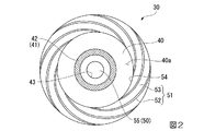
図2は、本実施形態に係る回転蛍光板30の円板40の第1の面40a側の構成図である。図3は、本実施形態に係る回転蛍光板30の円板40の第2の面40b側の構成図である。図4は、本実施形態に係る第1照明装置100の断面図である。図5は、本実施形態に係る第1照明装置100の分解斜視図である。図6は、本実施形態に係る回転蛍光板30に対する空気導入流路60の開口部60aの配置を示す図である。
Next, with reference to FIGS. 2-6, the structure of the
FIG. 2 is a configuration diagram on the
回転蛍光板30は、蛍光体層42を有する円板40をモーター50によって回転させる。モーター50は、例えば、アウターロータ型のモーターである。図2に示すように、蛍光体層42とヒートシンク51は、共に、円板40の第1の面40aに設けられている。一方、図3に示すように、モーター50の本体50a(ステータ)は、円板40の第1の面40aと反対側の第2の面40bに設けられている。
The
モーター50は、図2に示すように、円柱状のハブ55を有する。ハブ55は、ローターを構成し、本体50aに対して回転する。ハブ55の中心軸は、モーター50の回転中心となる。
円板40は、例えば、アルミや銅といった放熱性に優れた金属製の円板から構成されている。円板40は、第1の開口部43を有する。第1の開口部43は、円板40の中心に形成され、ハブ55と略同一の径を有し、ハブ55が嵌合可能な構成となっている。
As shown in FIG. 2, the
The
蛍光体層42は、例えば、YAG系蛍光体である(Y,Gd)3(Al,Ga)5O12:Ceを含有する層からなる。
反射膜41は、蛍光体層42と円板40との間に設けられており、蛍光体層42によって励起された蛍光Y(図1参照)を高い効率で反射するように設計されている。反射膜41は、例えば、銀等であり、少なくとも円板40よりも反射率が高い膜からなる。
反射膜41および蛍光体層42は、リング形状を持つ。
The
The
The
ヒートシンク51は、例えば、アルミ、銅、銀、鉄などといった放熱性に優れた金属材料から構成されている。ヒートシンク51は、円板40の第1の面40aに接着剤を介して固着される。接着剤としては、熱伝導性が高いシリコン系接着剤等を用いることができる。ヒートシンク51は、図2に示すように、複数のフィン52と、平板53とを含んでいる。
The
複数のフィン52は、平板53と一体で形成されている。複数のフィン52は、ハブ55の周囲を囲むように配置されている。複数のフィン52は、図2に示す平面視で、円板40の径方向外側から内側に向かって渦状となるように湾曲した突状部材から構成されている。この構成によれば、円板40の回転時に、モーター50の回転中心側から外側に空気の流れを形成することができる。
The plurality of
平板53は、円環形状を有し、第2の開口部54を有する。第2の開口部54は、平板53の中心に形成され、第1の開口部43よりも大きな径を有する。第2の開口部54の中には、ハブ55及び蛍光体層42が配置されている。すなわち、蛍光体層42は、複数のフィン52よりもモーター50の回転中心側に設けられている。
The
上記構成の回転蛍光板30は、図4に示すように、第1の面40aが、蛍光体層42を冷却する空気(図4において符号Fで示す)を導入する空気導入流路60の開口部60aと対向する。空気導入流路60は、光学部品用筐体61に設けられている。光学部品用筐体61は、コリメート集光光学系90やダイクロイックミラー80等の光学部品を収容する筐体であり、第1照明装置100を構成する。
As shown in FIG. 4, the rotating
光学部品用筐体61は、コリメート集光光学系90を取り付ける第1の取付部62と、ダイクロイックミラー80を取り付ける第2の取付部63と、を有する。コリメート集光光学系90は、図4に示すように、第1レンズ92、第2レンズ93、及び第3レンズ94がフレーム90aを介して一体化されたユニット部品となっている。
The
ユニット部品としてのコリメート集光光学系90は、図5に示すように、第1の取付部62に対しネジ64を介して取り付けられる。第1の取付部62には、ネジ64が螺合するネジ穴65が形成されている。一方、第2の取付部63は、図4に示すように、開口部66が形成された板形状を有する。ダイクロイックミラー80は、例えば、開口部66の周縁部に接着剤等を介して固定される。
As shown in FIG. 5, the collimator condensing
光学部品用筐体61には、第1の面40aに対し所定の距離をあけて対向する壁部67が設けられている。壁部67は、図5に示すように、円板形状を有する。壁部67の少なくとも一部は、光学部品用筐体61と一体で形成されている。本実施形態では、壁部67の一部が、コリメート集光光学系90のフレーム90aと一体で形成されており、壁部67の残部が、光学部品用筐体61と一体で形成されている。すなわち、光学部品用筐体61とフレーム90aとが協働して円板形状の壁部67を形成するようになっている。
The
壁部67は、図6に示すように、複数のフィン52よりも回転中心側に設けられている。壁部67は、平板53の内径(第2の開口部54)よりも僅かに小さい外径を有し、第2の開口部54より内側の領域のほぼすべてを覆うようになっている。この壁部67は、図4に示すように、第1の面40aからフィン52の先端までの長さよりも僅かに短い距離をあけて、第1の面40aに対して略平行に設けられている。
As shown in FIG. 6, the
空気導入流路60は、壁部67を貫通して設けられている。すなわち、空気導入流路60の出口である開口部60aは、壁部67に設けられている。なお、空気導入流路60の入口の開口部は、壁部67以外の場所(例えば、光学部品用筐体61の底面)に設けられており、プロジェクター1の機内または機外の空気を自然に取り込むようになっている。なお、空気導入流路60に対しては、ファン等で強制的に空気を送り込んでもよい。
The
図6に示すように、開口部60aの少なくとも一部は、蛍光体層42よりもモーター50の回転中心側に設けられている。開口部60aは、長方形状を有し、その短辺60a1は蛍光体層42の幅と略同一の幅を有する。開口部60aは、短辺60a1と直交する長辺60a2を有し、その一方が蛍光体層42よりも回転中心側に位置するように設けられている。逆に、開口部60aの短辺60a1及び外側の他方の長辺60a2は、蛍光体層42と対向するように設けられている。
As shown in FIG. 6, at least a part of the opening 60 a is provided closer to the rotation center of the
上記構成の回転蛍光板30において、コリメート集光光学系90を介して蛍光体層42にレーザー光からなる青色光Eが入射すると、蛍光体層42において熱が発生する。モーター50は、円板40を回転させることで、蛍光体層42における青色光Eの入射位置を順次変化させる。これにより、蛍光体層42の同じ部分に青色光Bが集中的に照射されて劣化するといった不具合の発生を防止できる。蛍光体層42において発生した熱の一部は、ヒートシンク51を介して放熱される。
In the
また、モーター50により円板40が回転すると、円板40の第1の面40aに設けられた複数のフィン52が回転し、円板40の回転中心側から外周側に空気の流れが誘起される(図4参照)。この空気の流れによって、空気導入流路60の入口から自然に空気が吸い込まれ、空気導入流路60の開口部60aから空気が導入される。開口部60aは第1の面40aに対向しており、開口部60aから導入された空気は、第1の面40aに沿って流れ、第1の面40aに設けられた蛍光体層42を直接的に冷却する。
Further, when the
このように、本実施形態によれば、蛍光体層42と複数のフィン52を同じ第1の面40aに設け、第1の面40aに空気導入流路60の開口部60aを対向させることで、蛍光体層42の表面に積極的に空気を流すことができ、蛍光体層42を十分に冷却することができる。
As described above, according to the present embodiment, the
また、本実施形態では、図6に示すように、開口部60aの少なくとも一部は、蛍光体層42よりもモーター50の回転中心側に設けられている。この構成によれば、蛍光体層42よりもモーター50の回転中心側に空気を導入することができる。複数のフィン52が回転すると、遠心力によって、円板40の回転中心側から外周側に空気の流れが誘起されるため、この空気の流れに乗って、蛍光体層42の表面を通過して外周に流れる空気の流量を増やすことができる。
In the present embodiment, as shown in FIG. 6, at least a part of the opening 60 a is provided closer to the rotation center of the
さらに、上記構成の回転蛍光板30においては、蛍光体層42が、複数のフィン52よりも回転中心側に設けられているため、複数のフィン52の設置スペースを広く確保でき、空気の流れの流量を増やすことができる。
このように、本実施形態の回転蛍光板30によれば、蛍光体層42の表面を通過して外周に流れる空気の流量を増やし、蛍光体層42を十分に冷却することができる。
Furthermore, in the
Thus, according to the
加えて、上記構成の第1照明装置100は、図4に示すように、第1の波長帯の青色光E及び第2の波長帯の蛍光Yを導くコリメート集光光学系90及びダイクロイックミラー80を収容する光学部品用筐体61と、光学部品用筐体61に設けられ、第1の面40aに対し所定の距離をあけて対向する壁部67と、を有する。この構成によれば、光学部品を収容する光学部品用筐体61に設けられた壁部67が、第1の面40aに対し所定の距離をあけて対向するため、第1の面40aとの間に流路が形成され、空気導入流路60の開口部60aから導入された空気が第1の面40aに沿って流れ易くなる。
In addition, as shown in FIG. 4, the
これにより、第1の面40aにおける熱交換によって温まった空気の滞留や循環流れが抑制され、空気導入流路60から導入される温度の低い空気の流量が増加するため、蛍光体層42を効率的に冷却することができる。
また、空気導入流路60は、壁部67を貫通して設けられている。この構成によれば、第1の面40aと壁部67との間に形成される流路に、温度の低い空気を直接導入することができ、蛍光体層42を効率的に冷却することができる。
Thereby, the retention and circulation flow of air warmed by heat exchange in the
Further, the
また、壁部67は、図5に示すように、その少なくとも一部が、光学部品用筐体61と一体で形成されている。このように、壁部67を光学部品用筐体61と一体で形成することで、部品点数を減らすことができる。このため、組み立て作業の容易化、及び、低コスト化に寄与できる。
Further, as shown in FIG. 5, at least a part of the
以上述べたように、本実施形態によれば、モーター50と、モーター50により回転する円板40と、円板40の第1の面40aに設けられた蛍光体層42及び複数のフィン52と、を備え、第1の面40aは、蛍光体層42を冷却する空気を導入する空気導入流路60の開口部60aと対向して設けられている回転蛍光板30を採用することによって、蛍光体層42を効率的に冷却することができる。また、回転蛍光板30を備えた第1照明装置100は、信頼性が高く、明るい照明光(白色光W)を生成できる。また、この第1照明装置100を備えたプロジェクター1は、品質に優れた画像を表示することができる。
As described above, according to the present embodiment, the
なお、本発明は、上記実施形態のものに必ずしも限定されるものではなく、本発明の趣旨を逸脱しない範囲において種々の変更を加えることが可能である。 In addition, this invention is not necessarily limited to the thing of the said embodiment, A various change can be added in the range which does not deviate from the meaning of this invention.
図7は、別実施形態に係る回転蛍光板30の円板40の第1の面40a側の構成図である。
図7に示す回転蛍光板30は、複数のフィン52が、蛍光体層42よりも回転中心側に設けられている点で、上記実施形態と異なる。
この構成によれば、複数のフィン52が蛍光体層42よりも回転中心側に設けられているため、複数のフィン52を小型にし、部品コストを下げることができる。
FIG. 7 is a configuration diagram on the
The
According to this configuration, since the plurality of
また、上記実施形態では、基材は金属製の円板40から構成され、蛍光体層42の青色光Eが入射する面は、蛍光Yが射出される射出面でもある場合を例示したが、これに限定されるものではない。例えば、円板40がサファイア等の光を透過する材質で、円板40の蛍光体層42が配置されていない第2の面40b側から青色光Eを入射させ、蛍光体層42が配置される第1の面40a側から蛍光Yを射出させる、いわゆる光透過型の構成にしてもよい。
Moreover, in the said embodiment, although the base material was comprised from the
また、上記実施形態では、開口部60aの一部が、蛍光体層42よりもモーター50の回転中心側に設けられている構成について例示したが、開口部60aの全部が、蛍光体層42よりもモーター50の回転中心側に設けられている構成を採用してもよい。
Moreover, in the said embodiment, although illustrated about the structure by which a part of opening
また、上記実施形態では、壁部67の一部が、光学部品用筐体61と一体で形成されている構成について例示したが、壁部67の全部が、光学部品用筐体61と一体で形成されている構成を採用してもよい。また、例えば、壁部67の全部が、フレーム90aと一体で形成され、光学部品用筐体61とは完全に別体で形成されている構成を採用してもよい。
Moreover, in the said embodiment, although the part of
また、上記実施形態では、壁部67は、平板53の内径(第2の開口部54)よりも僅かに小さい外径を有する構成について例示したが、これに限定されるものではない。例えば、壁部67を平板53の内径よりも大きくし、モーター50の回転中心軸の軸方向から見て、壁部67とフィン52の一部とが重なる構成にしてもよい。
Moreover, in the said embodiment, although the
また、上記実施形態では、3つの液晶光変調装置400R,400G,400Bを備えるプロジェクター1を例示したが、1つの液晶光変調装置でカラー映像を表示するプロジェクターに適用することも可能である。また、光変調装置として、デジタルミラーデバイス(DMD)を用いてもよい。また、波長変換素子として、量子ロッドを用いてもよい。
In the above-described embodiment, the
1…プロジェクター、10…第1光源(光源)、30…回転蛍光板(波長変換装置)、40…円板(基材)、40a…第1の面、40b…第2の面、41…反射膜、42…蛍光体層(波長変換素子)、43…第1の開口部、50…モーター(回転装置)、51…ヒートシンク、52…フィン、53…平板、60…空気導入流路、60a…開口部、61…光学部品用筐体、62…第1の取付部、63…第2の取付部、66…開口部、67…壁部、80…ダイクロイックミラー(光学部品)、90…コリメート集光光学系(光学部品)、90a…フレーム、92…第1レンズ、93…第2レンズ、94…第3レンズ、100…第1照明装置(照明装置)、400R,400G,400B…液晶光変調装置(光変調装置)、600…投写光学系、E…青色光(第1の波長帯の光)、F…空気、Y…蛍光(第2の波長帯の光)。
DESCRIPTION OF
Claims (11)
前記回転装置により回転中心軸を中心に回転する基材と、
前記基材の第1の面に設けられ、入射した光の波長を変換する波長変換素子と、
前記基材の前記第1の面に設けられた複数のフィンと、
を備え、
前記第1の面は、前記波長変換素子を冷却する空気を導入する空気導入流路の開口部と対向して設けられ、
前記波長変換素子の一部は、前記基材を前記回転中心軸の軸方向から見て、前記開口部と重なっていることを特徴とする波長変換装置。 A rotating device;
A base material that rotates about a rotation center axis by the rotation device;
A wavelength conversion element that is provided on the first surface of the substrate and converts the wavelength of incident light;
A plurality of fins provided on the first surface of the substrate;
With
The first surface is provided to face an opening of an air introduction flow channel for introducing air for cooling the wavelength conversion element,
Some of the wavelength conversion element sees the substrate from the axial direction of the rotation axis, the wavelength conversion device is characterized in that overlaps with the opening.
前記開口部の少なくとも一部は、前記基材を前記軸方向から見て、前記波長変換素子よりも前記回転中心軸側に設けられている波長変換装置。 The wavelength conversion device according to claim 1,
At least a part of the opening is a wavelength conversion device provided on the rotation center axis side of the wavelength conversion element when the substrate is viewed from the axial direction .
前記波長変換素子は、前記基材を前記軸方向から見て、前記複数のフィンよりも前記回転中心軸側に設けられている波長変換装置。 The wavelength converter according to claim 1 or 2,
The wavelength conversion device is a wavelength conversion device that is provided closer to the rotation center axis than the plurality of fins when the base is viewed from the axial direction .
前記複数のフィンは、前記基材を前記軸方向から見て、前記波長変換素子よりも前記回転中心軸側に設けられている波長変換装置。 The wavelength converter according to claim 1 or 2,
The plurality of fins is a wavelength conversion device provided on the rotation center axis side of the wavelength conversion element when the base is viewed from the axial direction .
前記開口部は、前記基材を前記軸方向から見て、前記回転中心軸に対して、前記波長変換素子に光が入射する部分とは反対側に設けられている波長変換装置。 The wavelength converter according to any one of claims 1 to 4,
The said opening part is a wavelength converter provided in the opposite side to the part into which light injects into the said wavelength conversion element with respect to the said rotation center axis, seeing the said base material from the said axial direction .
回転する前記基材の径方向における前記波長変換素子の幅は、前記開口部の幅と略等しい波長変換装置。 The wavelength converter according to any one of claims 1 to 5,
A wavelength conversion device in which the width of the wavelength conversion element in the radial direction of the rotating substrate is substantially equal to the width of the opening.
前記第1の波長帯の前記光を受けて第2の波長帯の光を射出する、請求項1から6のいずれか一項に記載の波長変換装置と、
を備えることを特徴する照明装置。 A light source that emits light in a first wavelength band;
The wavelength converter according to any one of claims 1 to 6 , which receives the light in the first wavelength band and emits light in a second wavelength band;
A lighting device comprising:
前記第1の波長帯の光及び前記第2の波長帯の光のうち少なくとも一方を導く光学部品と、
前記光学部品を収容する光学部品用筐体と、
をさらに備え、
前記光学部品用筐体は、前記第1の面に対し所定の距離をあけて対向する壁部を有する照明装置。 The lighting device according to claim 7,
An optical component that guides at least one of the light in the first wavelength band and the light in the second wavelength band;
An optical component housing that houses the optical component;
Further comprising
The optical component housing includes a wall portion facing the first surface with a predetermined distance therebetween.
前記壁部の少なくとも一部は、前記光学部品用筐体と一体で形成されている照明装置。 The lighting device according to claim 8,
A lighting device in which at least a part of the wall is formed integrally with the optical component casing.
前記空気導入流路は、前記壁部を貫通して設けられている照明装置。 The lighting device according to claim 8 or 9, wherein
The illuminating device, wherein the air introduction channel is provided through the wall.
前記照明装置からの照明光を画像情報に応じて変調することにより画像光を形成する光変調装置と、
前記画像光を投写する投写光学系と、
を備えることを特徴とするプロジェクター。 The lighting device according to any one of claims 7 to 10,
A light modulation device that forms image light by modulating illumination light from the illumination device according to image information; and
A projection optical system for projecting the image light;
A projector comprising:
Priority Applications (2)
| Application Number | Priority Date | Filing Date | Title |
|---|---|---|---|
| JP2015198266A JP6589534B2 (en) | 2015-10-06 | 2015-10-06 | Wavelength conversion device, illumination device, and projector |
| US15/284,089 US10203589B2 (en) | 2015-10-06 | 2016-10-03 | Wavelength converter, illuminator, and projector |
Applications Claiming Priority (1)
| Application Number | Priority Date | Filing Date | Title |
|---|---|---|---|
| JP2015198266A JP6589534B2 (en) | 2015-10-06 | 2015-10-06 | Wavelength conversion device, illumination device, and projector |
Publications (3)
| Publication Number | Publication Date |
|---|---|
| JP2017072671A JP2017072671A (en) | 2017-04-13 |
| JP2017072671A5 JP2017072671A5 (en) | 2018-10-18 |
| JP6589534B2 true JP6589534B2 (en) | 2019-10-16 |
Family
ID=58447928
Family Applications (1)
| Application Number | Title | Priority Date | Filing Date |
|---|---|---|---|
| JP2015198266A Active JP6589534B2 (en) | 2015-10-06 | 2015-10-06 | Wavelength conversion device, illumination device, and projector |
Country Status (2)
| Country | Link |
|---|---|
| US (1) | US10203589B2 (en) |
| JP (1) | JP6589534B2 (en) |
Families Citing this family (6)
| Publication number | Priority date | Publication date | Assignee | Title |
|---|---|---|---|---|
| WO2017169114A1 (en) * | 2016-03-31 | 2017-10-05 | ソニー株式会社 | Light source device, image display device, and optical unit |
| JP6888381B2 (en) | 2017-04-06 | 2021-06-16 | セイコーエプソン株式会社 | Light source device and projector |
| CN109521633A (en) * | 2017-09-19 | 2019-03-26 | 中强光电股份有限公司 | Lighting system and projection arrangement |
| CN111999970A (en) * | 2019-05-27 | 2020-11-27 | 中强光电股份有限公司 | Wavelength conversion module, light source device and projection equipment |
| CN112505996B (en) * | 2020-11-13 | 2023-06-13 | 无锡视美乐激光显示科技有限公司 | Wavelength conversion system |
| JP2022152154A (en) * | 2021-03-29 | 2022-10-12 | セイコーエプソン株式会社 | Wavelength conversion device, light source device, and projector |
Family Cites Families (17)
| Publication number | Priority date | Publication date | Assignee | Title |
|---|---|---|---|---|
| JP2003156796A (en) * | 2001-11-20 | 2003-05-30 | Fuji Photo Optical Co Ltd | Cooling fan integrated type rotary optical filter device and illumination optical system |
| JP2005062691A (en) * | 2003-08-19 | 2005-03-10 | Sharp Corp | Image projector |
| US20060066817A1 (en) * | 2004-09-30 | 2006-03-30 | Ke-Shu Chin | Color wheel |
| JP5354288B2 (en) * | 2009-09-30 | 2013-11-27 | カシオ計算機株式会社 | projector |
| JP2012008177A (en) * | 2010-06-22 | 2012-01-12 | Seiko Epson Corp | Fluorescent substance wheel and projector |
| JP5429079B2 (en) * | 2010-06-30 | 2014-02-26 | 株式会社Jvcケンウッド | Light source device and projection display device |
| TWI460525B (en) * | 2011-12-29 | 2014-11-11 | Hon Hai Prec Ind Co Ltd | Color wheel apparatus of porjector |
| CN103226283A (en) * | 2012-01-31 | 2013-07-31 | 鸿富锦精密工业(深圳)有限公司 | Color wheel device of projector |
| JP6015138B2 (en) * | 2012-05-31 | 2016-10-26 | 株式会社リコー | Image projection device |
| JP6079130B2 (en) * | 2012-10-24 | 2017-02-15 | 日亜化学工業株式会社 | Light source device and projector provided with the light source device |
| CN103807810B (en) * | 2012-11-14 | 2015-07-29 | 深圳市光峰光电技术有限公司 | Wavelength converter and related lighting fixtures |
| TWI480665B (en) * | 2013-07-03 | 2015-04-11 | Delta Electronics Inc | Heat dissipating module of phosphor wheel of laser projection system |
| CN104834169B (en) * | 2014-02-07 | 2017-04-12 | 中强光电股份有限公司 | Fluorescent wheel and projector with fluorescent wheel |
| DE102014102350B4 (en) * | 2014-02-24 | 2016-03-03 | Schott Ag | Converter arrangement with cooling for light sources with high luminance |
| CN106462042B (en) * | 2014-04-30 | 2018-08-31 | Nec显示器解决方案株式会社 | Structure for cooling down lamp optical system and projection display apparatus |
| US9664893B2 (en) * | 2014-09-17 | 2017-05-30 | Panasonic Intellectual Property Management Co., Ltd. | Phosphor wheel device, phosphor wheel device accommodating housing and projection-type image display device |
| TWI557493B (en) * | 2015-01-22 | 2016-11-11 | 中強光電股份有限公司 | Wavelength conversion module and projector |
-
2015
- 2015-10-06 JP JP2015198266A patent/JP6589534B2/en active Active
-
2016
- 2016-10-03 US US15/284,089 patent/US10203589B2/en active Active
Also Published As
| Publication number | Publication date |
|---|---|
| US20170097559A1 (en) | 2017-04-06 |
| US10203589B2 (en) | 2019-02-12 |
| JP2017072671A (en) | 2017-04-13 |
Similar Documents
| Publication | Publication Date | Title |
|---|---|---|
| JP6589534B2 (en) | Wavelength conversion device, illumination device, and projector | |
| EP3259521B1 (en) | Wavelength conversion device, illumination device, and projector | |
| JP5527059B2 (en) | Light source device and projector | |
| US10136111B2 (en) | Wavelength converter, illuminator, and projector | |
| JP6979572B2 (en) | Phosphor wheel and phosphor wheel device equipped with it, light conversion device, projection type display device | |
| JP2016066061A (en) | Phosphor wheel device, phosphor wheel device storage housing, and projection-type image display device | |
| US10890835B2 (en) | Light conversion device, light source apparatus, and projection display apparatus with improved cooling efficiency | |
| JP2014146056A (en) | Light source device and projector | |
| JP2012181431A (en) | Light source device and projector | |
| JP7113318B2 (en) | Light source device and projection type image display device | |
| WO2017073035A1 (en) | Wavelength conversion device, illuminating device, and projector | |
| JP2018004668A (en) | Light source device and projector | |
| JP2017116630A (en) | Wavelength conversion device, illumination device and projector | |
| JPWO2018042849A1 (en) | Projection display | |
| JP2017151213A (en) | Optical device, illumination device, and projector | |
| US10976649B2 (en) | Light source apparatus, image display apparatus, and optical unit | |
| JP2017072672A (en) | Wavelength converter, illumination apparatus and projector | |
| JP2017072670A (en) | Wavelength converter, illumination apparatus and projector | |
| JP2017072673A (en) | Wavelength converter, illumination apparatus and projector | |
| US12072616B2 (en) | Wavelength conversion device, light source device, and projector | |
| JP2017072669A (en) | Wavelength converter, illumination apparatus and projector | |
| WO2016132673A1 (en) | Wavelength conversion device, illumination device, and projector | |
| US20240255750A1 (en) | Phosphor unit, light source device, and projector | |
| JP2017130328A (en) | Wavelength conversion device, lighting device and projector | |
| JP2016146293A (en) | Wavelength conversion element, luminaire, and projector |
Legal Events
| Date | Code | Title | Description |
|---|---|---|---|
| RD05 | Notification of revocation of power of attorney |
Free format text: JAPANESE INTERMEDIATE CODE: A7425 Effective date: 20180906 |
|
| A521 | Written amendment |
Free format text: JAPANESE INTERMEDIATE CODE: A523 Effective date: 20180910 |
|
| A621 | Written request for application examination |
Free format text: JAPANESE INTERMEDIATE CODE: A621 Effective date: 20180910 |
|
| RD03 | Notification of appointment of power of attorney |
Free format text: JAPANESE INTERMEDIATE CODE: A7423 Effective date: 20181116 |
|
| A977 | Report on retrieval |
Free format text: JAPANESE INTERMEDIATE CODE: A971007 Effective date: 20190607 |
|
| A131 | Notification of reasons for refusal |
Free format text: JAPANESE INTERMEDIATE CODE: A131 Effective date: 20190611 |
|
| A521 | Written amendment |
Free format text: JAPANESE INTERMEDIATE CODE: A523 Effective date: 20190730 |
|
| TRDD | Decision of grant or rejection written | ||
| A01 | Written decision to grant a patent or to grant a registration (utility model) |
Free format text: JAPANESE INTERMEDIATE CODE: A01 Effective date: 20190820 |
|
| A61 | First payment of annual fees (during grant procedure) |
Free format text: JAPANESE INTERMEDIATE CODE: A61 Effective date: 20190902 |
|
| R150 | Certificate of patent or registration of utility model |
Ref document number: 6589534 Country of ref document: JP Free format text: JAPANESE INTERMEDIATE CODE: R150 |