JP6683246B2 - Refrigerator and manufacturing method thereof - Google Patents

Refrigerator and manufacturing method thereof Download PDF

Info

Publication number
JP6683246B2
JP6683246B2 JP2018507887A JP2018507887A JP6683246B2 JP 6683246 B2 JP6683246 B2 JP 6683246B2 JP 2018507887 A JP2018507887 A JP 2018507887A JP 2018507887 A JP2018507887 A JP 2018507887A JP 6683246 B2 JP6683246 B2 JP 6683246B2
Authority
JP
Japan
Prior art keywords
heat insulating
insulating material
vacuum heat
refrigerator
inner box
Prior art date
Legal status (The legal status is an assumption and is not a legal conclusion. Google has not performed a legal analysis and makes no representation as to the accuracy of the status listed.)
Active
Application number
JP2018507887A
Other languages
Japanese (ja)
Other versions
JPWO2017168571A1 (en
Inventor
右侑 兼松
右侑 兼松
俊 齋藤
俊 齋藤
Current Assignee (The listed assignees may be inaccurate. Google has not performed a legal analysis and makes no representation or warranty as to the accuracy of the list.)
Mitsubishi Electric Corp
Original Assignee
Mitsubishi Electric Corp
Priority date (The priority date is an assumption and is not a legal conclusion. Google has not performed a legal analysis and makes no representation as to the accuracy of the date listed.)
Filing date
Publication date
Application filed by Mitsubishi Electric Corp filed Critical Mitsubishi Electric Corp
Publication of JPWO2017168571A1 publication Critical patent/JPWO2017168571A1/en
Application granted granted Critical
Publication of JP6683246B2 publication Critical patent/JP6683246B2/en
Active legal-status Critical Current
Anticipated expiration legal-status Critical

Links

Images

Classifications

    • FMECHANICAL ENGINEERING; LIGHTING; HEATING; WEAPONS; BLASTING
    • F25REFRIGERATION OR COOLING; COMBINED HEATING AND REFRIGERATION SYSTEMS; HEAT PUMP SYSTEMS; MANUFACTURE OR STORAGE OF ICE; LIQUEFACTION SOLIDIFICATION OF GASES
    • F25DREFRIGERATORS; COLD ROOMS; ICE-BOXES; COOLING OR FREEZING APPARATUS NOT OTHERWISE PROVIDED FOR
    • F25D23/00General constructional features
    • F25D23/06Walls
    • FMECHANICAL ENGINEERING; LIGHTING; HEATING; WEAPONS; BLASTING
    • F25REFRIGERATION OR COOLING; COMBINED HEATING AND REFRIGERATION SYSTEMS; HEAT PUMP SYSTEMS; MANUFACTURE OR STORAGE OF ICE; LIQUEFACTION SOLIDIFICATION OF GASES
    • F25DREFRIGERATORS; COLD ROOMS; ICE-BOXES; COOLING OR FREEZING APPARATUS NOT OTHERWISE PROVIDED FOR
    • F25D23/00General constructional features
    • F25D23/08Parts formed wholly or mainly of plastics materials

Description

本発明は、真空断熱材を備えた冷蔵庫およびその製造方法に関するものである。   The present invention relates to a refrigerator provided with a vacuum heat insulating material and a method for manufacturing the same.

近年、地球温暖化防止といった地球環境保護の観点から、冷蔵庫においても省エネルギー化が求められている。一方で、市場では同じ設置スペースに対して大容量である容積効率の高い冷蔵庫のニーズが高まっている。そのため、冷蔵庫に用いられる断熱材として、断熱性能を強化することができ、更に断熱層を薄くできる真空断熱材が用いられるようになっている。   In recent years, from the viewpoint of global environment protection such as prevention of global warming, energy saving has been required also in refrigerators. On the other hand, in the market, there is an increasing need for a refrigerator with a large volume and a high volume efficiency in the same installation space. Therefore, as a heat insulating material used in a refrigerator, a vacuum heat insulating material that can enhance the heat insulating performance and can make the heat insulating layer thinner has been used.

ところで、一般的に、冷蔵庫に使用される真空断熱材は、ゴム系ホットメルトを接着面の全面に塗布することにより、内箱もしくは外箱に接着して固定されている。真空断熱材にゴム系ホットメルトを全面塗布する方法としては、例えば特許文献1に開示された断熱筐体のように、板状の真空断熱材をロールに通してホットメルトを転写する方法が知られている。なお、曲げ加工を施した立体形状を有する真空断熱材は、ロールを通すことができない。そこで、例えば特許文献2に開示された冷蔵庫のように、両面接着剤付きのシート材を貼り付けて接着を行っている。   By the way, generally, a vacuum heat insulating material used in a refrigerator is adhered and fixed to an inner box or an outer box by applying a rubber hot melt to the entire bonding surface. As a method of applying the rubber-based hot melt to the entire surface of the vacuum heat insulating material, there is known a method of transferring the hot melt by passing a plate-shaped vacuum heat insulating material through a roll like the heat insulating casing disclosed in Patent Document 1. Has been. The vacuum heat insulating material having a bent three-dimensional shape cannot be passed through a roll. Therefore, for example, as in the refrigerator disclosed in Patent Document 2, a sheet material with a double-sided adhesive is attached and bonded.

特開2007−155279号公報JP, 2007-155279, A 特開2009−228917号公報JP, 2009-228917, A

特許文献1のようなスチレンゴム系ホットメルトによる接着では、断熱筐体への硬質ウレタン発泡断熱材の充填および発泡工程まで、断熱筐体の加熱によりスチレンゴム系ホットメルトの粘度が低下する等の要因により、内箱の底面に配設された真空断熱材が内箱から剥がれて落下してしまう場合がある。   In styrene rubber-based hot melt bonding as in Patent Document 1, the viscosity of the styrene rubber-based hot melt decreases due to heating of the heat-insulated housing until the heat-insulated housing is filled with the rigid urethane foam insulation and the foaming process. Due to a factor, the vacuum heat insulating material disposed on the bottom surface of the inner box may peel off from the inner box and fall.

本発明は、上述のような課題を解決するためになされたものであり、断熱筐体の硬質ウレタン発泡断熱材の充填および発泡工程まで、内箱の底面に配設された真空断熱材が内箱から剥がれて落下すること防止できる冷蔵庫を提供することを目的とする。   The present invention has been made in order to solve the above-mentioned problems, and the vacuum heat insulating material disposed on the bottom surface of the inner box is filled up to the step of filling and foaming the hard urethane foam heat insulating material of the heat insulating casing. An object of the present invention is to provide a refrigerator that can be prevented from falling off from a box.

本発明に係る冷蔵庫は、外箱と、前記外箱に収納され、前記外箱との間に内部空間を形成する内箱と、前記内部空間内であって、前記内箱の底壁に接着されるL字状の真空断熱材と、前記内部空間内に設けられた発泡断熱材と、前記真空断熱材における前記内箱との面接触部に生じる応力集中領域に、L字状の前記真空断熱材の屈曲部分が延びる方向のみに沿って線状に設けられ、前記真空断熱材が重力により剥がれて落下することを防止する接着剤と、を備えたものである。 A refrigerator according to the present invention includes an outer box, an inner box that is housed in the outer box and forms an inner space between the outer box and the inner box, and is bonded to a bottom wall of the inner box. The L-shaped vacuum heat insulating material, the foam heat insulating material provided in the internal space, and the L-shaped vacuum in the stress concentration region generated in the surface contact portion of the vacuum heat insulating material with the inner box. An adhesive that is provided linearly only along the direction in which the bent portion of the heat insulating material extends and that prevents the vacuum heat insulating material from peeling off and falling due to gravity.

本発明に係る冷蔵庫およびその製造方法は、L字状の真空断熱材の応力集中領域に接着剤が線状、ドット状、又は波線状に設けられているので、真空断熱材を内箱に強固に接着することができ、断熱筐体の硬質ウレタン発泡断熱材の充填および発泡工程まで、真空断熱材が内箱から剥がれて落下することがない。   In the refrigerator and the manufacturing method thereof according to the present invention, since the adhesive is provided in the stress concentration region of the L-shaped vacuum heat insulating material in a linear shape, a dot shape, or a wavy shape, the vacuum heat insulating material is firmly attached to the inner box. The vacuum heat insulating material is prevented from peeling off from the inner box and dropping until the process of filling and foaming the hard urethane foam heat insulating material of the heat insulating casing.

本発明の実施の形態1に係る冷蔵庫の側面方向から見た断面図である。It is sectional drawing seen from the side surface direction of the refrigerator which concerns on Embodiment 1 of this invention. 本発明の実施の形態1に係る冷蔵庫の組立工程を示した説明図である。It is explanatory drawing which showed the assembly process of the refrigerator which concerns on Embodiment 1 of this invention. 本発明の実施の形態1に係る冷蔵庫の真空断熱材の製造工程の概要を示した説明図である。It is explanatory drawing which showed the outline of the manufacturing process of the vacuum heat insulating material of the refrigerator which concerns on Embodiment 1 of this invention. (A)はL字状の真空断熱材の正面図、(B)はL字状の真空断熱材の平面図、(C)はL字状の真空断熱材を内箱に面接着させた場合における接着剤に負荷される応力分布図である。(A) is a front view of the L-shaped vacuum heat insulating material, (B) is a plan view of the L-shaped vacuum heat insulating material, and (C) is a case where the L-shaped vacuum heat insulating material is surface-bonded to the inner box. FIG. 6 is a stress distribution diagram loaded on the adhesive in FIG. (A)は線状のスチレンゴム系ホットメルトを設けた真空断熱材の正面図、(B)は(A)の平面図である。(A) is a front view of a vacuum heat insulating material provided with a linear styrene rubber-based hot melt, and (B) is a plan view of (A). (A)は本発明の実施の形態2に係る冷蔵庫の真空断熱材の正面図、(B)は(A)の平面図である。(A) is a front view of the vacuum heat insulating material of the refrigerator which concerns on Embodiment 2 of this invention, (B) is a top view of (A). (A)は本発明の実施の形態3に係る冷蔵庫の真空断熱材の正面図、(B)は(A)の平面図である。(A) is a front view of the vacuum heat insulating material of the refrigerator which concerns on Embodiment 3 of this invention, (B) is a top view of (A). (A)は本発明の実施の形態4に係る冷蔵庫の真空断熱材の正面図、(B)は(A)の平面図である。(A) is a front view of the vacuum heat insulating material of the refrigerator which concerns on Embodiment 4 of this invention, (B) is a top view of (A). (A)は本発明の実施の形態5に係る冷蔵庫の真空断熱材の正面図、(B)は(A)の平面図である。(A) is a front view of the vacuum heat insulating material of the refrigerator which concerns on Embodiment 5 of this invention, (B) is a top view of (A). (A)は本発明の実施の形態6に係る冷蔵庫の真空断熱材の正面図、(B)は(A)の平面図である。(A) is a front view of the vacuum heat insulating material of the refrigerator which concerns on Embodiment 6 of this invention, (B) is a top view of (A).

実施の形態1.
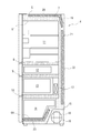
本発明の実施の形態1に係る冷蔵庫を図面に基づいて説明する。先ず、冷蔵庫4の構成の一例を図1および図2に基づいて説明する。図1は、本発明の実施の形態1に係る冷蔵庫の側面方向から見た断面図である。図2は、本発明の実施の形態1に係る冷蔵庫の組立工程を示した説明図である。
Embodiment 1.
A refrigerator according to Embodiment 1 of the present invention will be described with reference to the drawings. First, an example of the configuration of the refrigerator 4 will be described with reference to FIGS. 1 and 2. 1 is a cross-sectional view of a refrigerator according to Embodiment 1 of the present invention as seen from a side direction. FIG. 2 is an explanatory diagram showing an assembling process of the refrigerator according to the first embodiment of the present invention.

冷蔵庫4は、第一隔壁8と、第二隔壁9と、第三隔壁10とにより、冷蔵室11と、製氷室及び切替室12と、冷凍室13と、野菜室14とに区分けされている。冷蔵庫4において、最上部には冷蔵室11が形成され、上から順に製氷室及び切替室12と、冷凍室13と、最下部を野菜室14とする貯蔵室が形成されている。具体的には、冷蔵室11は、第一隔壁8の上部に区分けされ、冷蔵温度(+5℃程度)に維持されている。製氷室及び切替室12は、第一隔壁8の下部と第二隔壁9の上部とで形成される空間に区分けされ、製氷室では凍結温度(−20℃程度)、切替室では過冷却温度(−7〜0℃)に維持されている。冷凍室13は、第二隔壁9の下部と第三隔壁10とで形成される空間に区分けされ、凍結温度(−20℃程度)に維持されている。野菜室14は、第三隔壁10の下部に区分けされ、冷蔵温度(+5℃程度)に維持されている。ただし、第一隔壁8、第二隔壁9及び第三隔壁10は、部屋間に温度差がなければ、配設しなくてもよい。また、冷蔵室11、製氷室及び切替室12、冷凍室13及び野菜室14の順序や構成も図示した実施の形態に限定するものではなく、種々のバリエーションで実施するものとする。   The refrigerator 4 is divided into a refrigerating compartment 11, an ice making compartment and a switching compartment 12, a freezing compartment 13, and a vegetable compartment 14 by a first partition 8, a second partition 9, and a third partition 10. . In the refrigerator 4, a refrigerating compartment 11 is formed at the uppermost portion, and an ice making compartment and a switching compartment 12, a freezing compartment 13, and a storage compartment having a lowermost portion as a vegetable compartment 14 are formed in order from the top. Specifically, the refrigerating chamber 11 is sectioned above the first partition wall 8 and is maintained at a refrigerating temperature (about + 5 ° C.). The ice making chamber and the switching chamber 12 are divided into a space formed by the lower portion of the first partition wall 8 and the upper portion of the second partition wall 9, and the freezing temperature (about -20 ° C) in the ice making chamber and the supercooling temperature (in the switching chamber) ( -7 to 0 ° C). The freezing chamber 13 is divided into a space formed by the lower part of the second partition wall 9 and the third partition wall 10, and is maintained at a freezing temperature (about -20 ° C). The vegetable compartment 14 is sectioned below the third partition 10 and is maintained at a refrigerating temperature (about + 5 ° C.). However, the first partition wall 8, the second partition wall 9, and the third partition wall 10 may not be provided as long as there is no temperature difference between the rooms. Further, the order and structure of the refrigerating room 11, the ice making room and the switching room 12, the freezing room 13 and the vegetable room 14 are not limited to the illustrated embodiment, but may be implemented in various variations.

冷蔵庫4は、図1に示すように、鉄板などの金属をU字形に曲げて冷蔵庫4の天井及び両側面を形成する外箱5と、ABSなどの合成樹脂からなり、外箱5の内部に挿入され、外箱との間に内部空間を形成する内箱6とで本体が構成されている。冷蔵庫4の天面、背面及び底面における外箱5と内箱6との内部空間には、真空断熱材20、21、23がそれぞれ配設されており、周囲の隙間には硬質ウレタン発泡断熱材7が充填されている。   As shown in FIG. 1, the refrigerator 4 includes an outer box 5 formed by bending a metal such as an iron plate into a U shape to form the ceiling and both side surfaces of the refrigerator 4, and a synthetic resin such as ABS. The main body is configured with an inner box 6 that is inserted and forms an internal space between the inner box 6 and the outer box. Vacuum heat insulating materials 20, 21, and 23 are arranged in the inner spaces of the outer box 5 and the inner box 6 on the top, back, and bottom of the refrigerator 4, respectively, and a hard urethane foam heat insulating material is provided in the surrounding space. 7 is filled.

内箱6は、図1に示すように、底壁6Aの後部が階段状に立ち上がる立体形状を成し、底壁6Aの背面に機械室15が形成されている。機械室15の内部には、圧縮機16と凝縮器18が配設されている。また、冷凍室13の後部には、冷蔵室11、製氷室及び切替室12、冷凍室13、野菜室14の各室を所定の温度帯に冷却する冷却器17が配設されている。冷却器17と、圧縮機16と、凝縮器18とがパイプで結合されて、冷凍サイクルが構築されている。   As shown in FIG. 1, the inner box 6 has a three-dimensional shape in which the rear portion of the bottom wall 6A rises in a stepwise manner, and a machine room 15 is formed on the back surface of the bottom wall 6A. Inside the machine room 15, a compressor 16 and a condenser 18 are arranged. Further, at the rear of the freezing compartment 13, a cooler 17 is provided for cooling each of the refrigerating compartment 11, the ice making and switching compartment 12, the freezing compartment 13 and the vegetable compartment 14 to a predetermined temperature zone. The cooler 17, the compressor 16, and the condenser 18 are connected by a pipe to construct a refrigeration cycle.

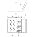
図3は、本発明の実施の形態1に係る冷蔵庫の真空断熱材の製造工程の概要を示した説明図である。真空断熱材1は、図3に示すように、ガスバリア性フィルムからなる外被材2の内部に無機繊維集合体の芯材3が挿入され、その後、外被材2の内部を真空化させた構成である。冷蔵庫4の内箱6の底面及び天面に配設された真空断熱材20、23は、図3に示す板状の真空断熱材1をL字状に曲げた形状である。   FIG. 3 is an explanatory diagram showing an outline of the manufacturing process of the vacuum heat insulating material of the refrigerator according to the first embodiment of the present invention. As shown in FIG. 3, in the vacuum heat insulating material 1, the core material 3 of the inorganic fiber aggregate is inserted into the outer covering material 2 made of a gas barrier film, and then the inside of the outer covering material 2 is evacuated. It is a composition. The vacuum heat insulating materials 20 and 23 arranged on the bottom surface and the top surface of the inner box 6 of the refrigerator 4 are formed by bending the plate-like vacuum heat insulating material 1 shown in FIG. 3 into an L shape.

ここで、冷蔵庫4の内箱6の底面及び天面に配設された真空断熱材20、23は、L字状に形成されている。冷蔵庫4は、図1に示すように、天井背面に運転制御のための電子制御基板19が配設されている。電子制御基板19は、自己発熱部品である。そのため、内箱6と電子制御基板19との間に、断熱効果がウレタンよりも高い真空断熱材20を配置することが好ましい。また、冷蔵庫4は、天井に放熱パイプ(図示することは省略)が配設しているため、放熱パイプと内箱6との間にも真空断熱材20を配設することが好ましい。そこで、冷蔵庫4の天面に配置された真空断熱材20は、板状の真空断熱材1をL字状に曲げた形状とされ、スチレンゴム系ホットメルトを塗布して外箱5に接着され、冷蔵庫4の天井と電子制御基板19とを同時に被覆している。つまり、真空断熱材20は、L字状とすることにより、製造コストを削減することができる。なお、L字状の真空断熱材20は、屈曲部分を折り曲げた形状に限定されず、例えば湾曲させた形状として実施することもできる。   Here, the vacuum heat insulating materials 20 and 23 arranged on the bottom surface and the top surface of the inner box 6 of the refrigerator 4 are formed in an L shape. As shown in FIG. 1, the refrigerator 4 is provided with an electronic control board 19 for operation control on the rear surface of the ceiling. The electronic control board 19 is a self-heating component. Therefore, it is preferable to dispose the vacuum heat insulating material 20 having a higher heat insulating effect than urethane between the inner box 6 and the electronic control board 19. Further, since the refrigerator 4 has a radiation pipe (not shown) arranged on the ceiling, it is preferable to also arrange the vacuum heat insulating material 20 between the radiation pipe and the inner box 6. Therefore, the vacuum heat insulating material 20 arranged on the top surface of the refrigerator 4 has a shape in which the plate-like vacuum heat insulating material 1 is bent into an L shape, and is applied to the outer box 5 by applying styrene rubber hot melt. The roof of the refrigerator 4 and the electronic control board 19 are simultaneously covered. That is, the vacuum heat insulating material 20 can reduce the manufacturing cost by forming the L shape. The L-shaped vacuum heat insulating material 20 is not limited to the bent shape of the bent portion, and may be, for example, a curved shape.

また、冷蔵庫4は、機械室15に配設された圧縮機16と凝縮器18とが運転時に自己発熱する。そのため、冷蔵庫4の床から熱の侵入を防ぐ必要があり、電子制御基板19の場合と同様の理由により、内箱6と機械室15との間に、真空断熱材23を配設することが好ましい。そこで、冷蔵庫4の床面に配置された真空断熱材23は、冷蔵庫4の床面と機械室15を被覆するように、板状の真空断熱材1をL字に曲げた形状とされ、スチレンゴム系ホットメルトを塗布して内箱6に接着されている。なお、L字状の真空断熱材20の屈曲部分は、例えば湾曲させた形状として実施することもできる。   Further, in the refrigerator 4, the compressor 16 and the condenser 18 arranged in the machine room 15 generate heat during operation. Therefore, it is necessary to prevent heat from entering from the floor of the refrigerator 4, and for the same reason as in the case of the electronic control board 19, the vacuum heat insulating material 23 may be arranged between the inner box 6 and the machine room 15. preferable. Therefore, the vacuum heat insulating material 23 disposed on the floor surface of the refrigerator 4 is formed by bending the plate-like vacuum heat insulating material 1 into an L shape so as to cover the floor surface of the refrigerator 4 and the machine room 15. A rubber hot melt is applied and adhered to the inner box 6. In addition, the bent portion of the L-shaped vacuum heat insulating material 20 may be formed in a curved shape, for example.

なお、冷蔵庫4の背面に配設された真空断熱材21は、背面金属部品22にスチレンゴム系ホットメルトを塗布して接着されている。   The vacuum heat insulating material 21 provided on the back surface of the refrigerator 4 is adhered to the back metal part 22 by applying styrene rubber hot melt.

真空断熱材23は、図2に示すように、内箱6の床面に設置した場合、冷蔵庫4の床面に床面金属部品24で蓋をした後、筐体を起立させ、冷蔵庫4のフランジにネジ打ち等を行う。このとき、冷蔵庫4の床面に設置された真空断熱材23は、落下方向である垂直方向に自重が作用する。   As shown in FIG. 2, when the vacuum heat insulating material 23 is installed on the floor surface of the inner box 6, after covering the floor surface of the refrigerator 4 with the floor surface metal parts 24, the housing is erected and the refrigerator 4 is installed. Screw the flange. At this time, the vacuum heat insulating material 23 installed on the floor surface of the refrigerator 4 has its own weight acting in the vertical direction, which is the falling direction.

図4(A)はL字状の真空断熱材の正面図、図4(B)はL字状の真空断熱材の平面図、図4(C)はL字状の真空断熱材を内箱に面接着させた場合における接着剤に負荷される応力分布図である。図4(C)において、横軸は接着面の位置、縦軸は負荷応力を示している。内箱6と真空断熱材20とを面接触させた場合の接着剤の負荷応力は、図4(C)に示すように、L字の曲げ起点位置が最も高く(σmax)、それ以降は徐々に減少していく。応力集中領域Yとは、図4(B)に示すように、全領域内における最大応力(σmax)を、実験や計算等により得られた所定値aを乗じた応力(a・σmax)以上の応力領域を指す。ここで、所定値a、応力集中領域Yは、真空断熱材23の長さL、内箱6に当接する部分の長さA、折り曲げられた曲げ部分の長さBによって決まる。例えば、真空断熱材23と内箱6との接着面Zにおいて、内箱6と真空断熱材23とを面接着した場合の応力分布は、図4(A)に示すA寸法とB寸法によって決まる。具体的には、A寸法を400mm、B寸法を150mmとすると、所定値aは、0.28〜0.32程度になるので、応力集中領域Yは、112mm〜128mm程度となる。したがって、応力集中領域Yは、曲げ起点位置より112mm〜128mmとなる。仮に、応力集中領域Yの寸法を120mmとすれば、真空断熱材23の端面から280mm〜400mmの領域にスチレンゴム系ホットメルト30を設けることが有効である。したがって、応力集中領域Yは、所定値aが0.32の場合は128mmとなるので、128mm以上であれば良く、B寸法である150mm以上と考えて接着剤を塗布すればよい。4A is a front view of the L-shaped vacuum heat insulating material, FIG. 4B is a plan view of the L-shaped vacuum heat insulating material, and FIG. 4C is an inner box of the L-shaped vacuum heat insulating material. FIG. 6 is a stress distribution diagram applied to the adhesive when surface-bonded to the adhesive. In FIG. 4C, the horizontal axis represents the position of the adhesive surface and the vertical axis represents the load stress. As shown in FIG. 4C, the load stress of the adhesive when the inner box 6 and the vacuum heat insulating material 20 are in surface contact with each other is highest at the L-shaped bending start position (σ max ), and thereafter. It gradually decreases. The stress concentration area Y, FIG. 4 (B) as shown in, the maximum stress (sigma max) in the entire region, multiplied by the predetermined value a obtained by experiment or calculation, etc. Stress (a · σ max) Indicates the above stress region. Here, the predetermined value a and the stress concentration region Y are determined by the length L of the vacuum heat insulating material 23, the length A of the portion contacting the inner box 6, and the length B of the bent portion. For example, in the bonding surface Z between the vacuum heat insulating material 23 and the inner box 6, the stress distribution when the inner box 6 and the vacuum heat insulating material 23 are surface-bonded is determined by the A and B dimensions shown in FIG. 4 (A). . Specifically, assuming that the A dimension is 400 mm and the B dimension is 150 mm, the predetermined value a is about 0.28 to 0.32, so the stress concentration region Y is about 112 mm to 128 mm. Therefore, the stress concentration region Y is 112 mm to 128 mm from the bending start position. If the size of the stress concentration region Y is 120 mm, it is effective to provide the styrene rubber hot melt 30 in a region of 280 mm to 400 mm from the end surface of the vacuum heat insulating material 23. Therefore, since the stress concentration region Y is 128 mm when the predetermined value a is 0.32, the stress concentration region Y may be 128 mm or more, and the adhesive may be applied considering that the dimension B is 150 mm or more.

また、ABS等の合成樹脂でなる内箱6は、耐熱温度が70度程度であるのに対し、スチレンゴム系ホットメルトは、塗布時に180度程度の高温に加熱して粘度を上昇させた状態にある。そのため、スチレンゴム系ホットメルトは、内箱6に直接塗布することができない。そこで、内箱6と真空断熱材23とを接着する場合、スチレンゴム系ホットメルトを真空断熱材23の表面に塗布し、ABS等の合成樹脂の耐熱温度帯である60度以下に冷却してから行う必要がある。冷却後のスチレンゴム系ホットメルトは、粘度が低下して、接着強度が低くなる。その上、例えばL字状に形成された真空断熱材23の場合は、接着剤への負荷が均一ではないため、真空断熱材が配置位置から剥がれて、内箱6から落下する問題がある。   The heat resistance temperature of the inner box 6 made of synthetic resin such as ABS is about 70 degrees, whereas the styrene rubber hot melt is heated to a high temperature of about 180 degrees at the time of application to increase the viscosity. It is in. Therefore, the styrene rubber hot melt cannot be directly applied to the inner box 6. Therefore, when adhering the inner box 6 and the vacuum heat insulating material 23, styrene rubber hot melt is applied to the surface of the vacuum heat insulating material 23 and cooled to 60 ° C. or lower which is a heat resistant temperature range of synthetic resin such as ABS. Need to do from. After cooling, the styrene rubber hot melt has a reduced viscosity and a low adhesive strength. Moreover, for example, in the case of the vacuum heat insulating material 23 formed in an L shape, since the load on the adhesive is not uniform, there is a problem that the vacuum heat insulating material is peeled from the arrangement position and falls from the inner box 6.

更に、スチレンゴム系ホットメルトは、両面接着テープに比べて、安価な材料であるため、真空断熱材20、21、23の接着に好適である。例えば、曲げ加工を施した真空断熱材をスチレンゴム系ホットメルトで接着する場合、線状に形成したスチレンゴム系ホットメルトを等間隔に塗工する方法が知られている。一方、板状の真空断熱材1をL字状に曲げてスチレンゴム系ホットメルト30で接着する場合では、製造において粘着面をもった状態での曲げ加工は困難であるため、予め曲げ加工を行った上で、スチレンゴム系ホットメルトの塗布が行われている。しかし、製造コストの観点から、L字の曲げ土台面と曲げ立ち上がり面のどちらか一方に塗布することが好ましい。   Further, the styrene rubber-based hot melt is an inexpensive material as compared with the double-sided adhesive tape, and thus is suitable for bonding the vacuum heat insulating materials 20, 21, and 23. For example, when bonding a vacuum heat insulating material that has been subjected to bending with a styrene rubber hot melt, a method is known in which linearly formed styrene rubber hot melt is applied at equal intervals. On the other hand, when the plate-shaped vacuum heat insulating material 1 is bent into an L-shape and bonded with the styrene rubber-based hot melt 30, it is difficult to bend the plate with the adhesive surface in the manufacturing process. After that, the styrene rubber-based hot melt is applied. However, from the viewpoint of manufacturing cost, it is preferable to apply the coating on either the L-shaped bending base surface or the bending rising surface.

図5(A)は線状のスチレンゴム系ホットメルトを設けた真空断熱材の正面図、図5(B)は(A)の平面図である。そこで、実施の形態1の冷蔵庫4では、図5(A)、(B)に示すように、真空断熱材23の応力集中領域Yに線状のスチレンゴム系ホットメルト30からなる接着剤を、所定の間隔を開けて複数列(図示例の場合は6列)設けて、真空断熱材23と内箱6との間の接着力を強化している。   FIG. 5 (A) is a front view of a vacuum heat insulating material provided with a linear styrene rubber hot melt, and FIG. 5 (B) is a plan view of (A). Therefore, in the refrigerator 4 of the first embodiment, as shown in FIGS. 5 (A) and 5 (B), a linear styrene rubber hot melt 30 adhesive is applied to the stress concentration region Y of the vacuum heat insulating material 23. A plurality of rows (six rows in the illustrated example) are provided at a predetermined interval to strengthen the adhesive force between the vacuum heat insulating material 23 and the inner box 6.

スチレンゴム系ホットメルト30は、L字状の真空断熱材23の直上にホットメルト塗布ノズルを直線状に移動させる、もしくは真空断熱材23を直線的に移動させ、ノズル吐出されるスチレンゴム系ホットメルト30のカーテンを通すことにより線状に形成される。線状のスチレンゴム系ホットメルト30を塗布した真空断熱材23は、冷蔵庫4の組立コンベア上を移動する内箱6の床面に接着される。そして、冷蔵庫4の床面に床面金属部品24で蓋がされ、圧縮機16を配設する為の圧縮機スタンド25が取り付けられる。その後、筐体は、一度起立させ、冷蔵庫4のフランジにネジ打ち等が行われ、再度横置きにされる。最後に、背面金属部品22で蓋がされ、ウレタン注入口26から硬質ウレタン発泡断熱材7の充填・発泡が行われ、断熱筐体が形成される。このようにして、内箱6は、周囲を外箱5と背面金属部品22と床面金属部品24とで覆われる。   The styrene rubber hot melt 30 is a styrene rubber hot melt discharged from the nozzle by moving the hot melt coating nozzle linearly directly above the L-shaped vacuum heat insulating material 23 or moving the vacuum heat insulating material 23 linearly. A linear shape is formed by passing a curtain of the melt 30. The vacuum heat insulating material 23 coated with the linear styrene rubber hot melt 30 is adhered to the floor surface of the inner box 6 moving on the assembly conveyor of the refrigerator 4. Then, the floor surface of the refrigerator 4 is covered with a floor metal component 24, and a compressor stand 25 for mounting the compressor 16 is attached. After that, the housing is once erected, the flange of the refrigerator 4 is screwed, and the housing is placed horizontally again. Finally, the back metal part 22 is covered, and the rigid urethane foam heat insulating material 7 is filled and foamed from the urethane inlet 26 to form a heat insulating casing. In this way, the inner box 6 is covered with the outer box 5, the rear metal component 22, and the floor metal component 24 on the periphery.

したがって、実施の形態1の冷蔵庫4は、内箱6の底面に配設されたL字状の真空断熱材23が内箱6に強固に接着されているので、断熱筐体の硬質ウレタン発泡断熱材7の充填および発泡工程まで、真空断熱材23が内箱6から剥がれて落下することがない。また、実施の形態1の冷蔵庫4は、スチレンゴム系ホットメルト30を必要とする箇所である応力集中領域Yにのみ設けた構成なので、使用材料を低減でき、経済的効果を奏する。   Therefore, in the refrigerator 4 according to the first embodiment, the L-shaped vacuum heat insulating material 23 arranged on the bottom surface of the inner box 6 is firmly adhered to the inner box 6, so that the hard urethane foam heat insulation of the heat insulating casing is performed. The vacuum heat insulating material 23 does not peel off from the inner box 6 and fall until the filling and foaming steps of the material 7. Further, since the refrigerator 4 of the first embodiment is configured to be provided only in the stress concentration region Y where the styrene rubber-based hot melt 30 is required, the amount of material used can be reduced and an economic effect can be achieved.

実施の形態2.
次に、実施の形態2の冷蔵庫を図6に基づいて説明する。図6(A)は本発明の実施の形態2に係る冷蔵庫の真空断熱材の正面図、図6(B)は図6(A)の平面図である。なお、実施の形態1の冷蔵庫と同一の構成について、その説明を適宜省略する。
Embodiment 2.
Next, the refrigerator according to the second embodiment will be described with reference to FIG. FIG. 6 (A) is a front view of the vacuum heat insulating material of the refrigerator according to Embodiment 2 of the present invention, and FIG. 6 (B) is a plan view of FIG. 6 (A). Note that description of the same configuration as the refrigerator of the first embodiment will be appropriately omitted.

実施の形態2の冷蔵庫4は、L字状の真空断熱材23の応力集中領域Yに、接着剤であるスチレンゴム系ホットメルト31がドット状に設けられた構成である。ドット状のスチレンゴム系ホットメルト31は、真空断熱材23にホットメルト塗布ノズルのバルブを開閉することにより塗布される。なお、その他の構成は、実施の形態1の冷蔵庫と同じである。   The refrigerator 4 of the second embodiment has a configuration in which the stress-concentrated region Y of the L-shaped vacuum heat insulating material 23 is provided with the styrene rubber hot melt 31 as an adhesive in a dot shape. The dot-shaped styrene rubber hot melt 31 is applied to the vacuum heat insulating material 23 by opening and closing the valve of the hot melt application nozzle. The rest of the configuration is the same as that of the refrigerator of the first embodiment.

実施の形態2の冷蔵庫4は、真空断熱材23の応力集中領域Yに、スチレンゴム系ホットメルト31をドット状に設けて、真空断熱材23と内箱6との間の接着力が強化されているので、実施の形態1で説明した線状のスチレンゴム系ホットメルト30に比べて、負荷応力に対して二次元的に密度を変化せることができ、より効果的に接着強度を高めることができる。つまり、L字状の真空断熱材23は、内箱6に強固に接着されているので、断熱筐体の硬質ウレタン発泡断熱材7の充填および発泡工程まで、内箱6から剥がれて落下することがない。また、実施の形態2の冷蔵庫4は、スチレンゴム系ホットメルト31を必要とする箇所である応力集中領域Yにのみ設けた構成なので、使用材料を低減でき、経済的効果を奏する。   In the refrigerator 4 according to the second embodiment, the styrene rubber-based hot melt 31 is provided in a dot shape in the stress concentration region Y of the vacuum heat insulating material 23 to enhance the adhesive force between the vacuum heat insulating material 23 and the inner box 6. Therefore, as compared with the linear styrene rubber-based hot melt 30 described in the first embodiment, the density can be changed two-dimensionally with respect to the load stress, and the adhesive strength can be increased more effectively. You can That is, since the L-shaped vacuum heat insulating material 23 is firmly adhered to the inner box 6, the L-shaped vacuum heat insulating material 23 should be peeled off from the inner box 6 and dropped until the process of filling and foaming the hard urethane foam heat insulating material 7 of the heat insulating casing. There is no. Further, since the refrigerator 4 according to the second embodiment has a configuration in which it is provided only in the stress concentration region Y where the styrene rubber hot melt 31 is required, the amount of materials used can be reduced and an economic effect can be achieved.

実施の形態3.
次に、実施の形態3の冷蔵庫を図7に基づいて説明する。図7(A)は本発明の実施の形態3に係る冷蔵庫の真空断熱材の正面図、図7(B)は図7(A)の平面図である。なお、実施の形態1の冷蔵庫と同一の構成について、その説明を適宜省略する。
Embodiment 3.
Next, the refrigerator according to the third embodiment will be described with reference to FIG. FIG. 7 (A) is a front view of a vacuum heat insulating material of a refrigerator according to Embodiment 3 of the present invention, and FIG. 7 (B) is a plan view of FIG. 7 (A). Note that description of the same configuration as the refrigerator of the first embodiment will be appropriately omitted.

実施の形態3の冷蔵庫4は、L字状の真空断熱材23の応力集中領域Yに、接着剤であるスチレンゴム系ホットメルト32が波線状に設けられた構成である。図7(B)に示す実施の形態3では、一例として波線状のスチレンゴム系ホットメルト32が、所定の間隔を開けて4列設けられている。なお、その他の構成は実施の形態1の冷蔵庫と同じである。   The refrigerator 4 according to the third embodiment has a configuration in which a styrene rubber hot melt 32 as an adhesive is provided in a wavy line in the stress concentration region Y of the L-shaped vacuum heat insulating material 23. In the third embodiment shown in FIG. 7B, as an example, wavy linear styrene rubber-based hot melts 32 are provided in four rows at predetermined intervals. The rest of the configuration is the same as that of the refrigerator of the first embodiment.

波線状のスチレンゴム系ホットメルト32は、真空断熱材23の直上においてホットメルト塗布ノズルを波線状に移動させることにより塗布される。或いは、真空断熱材23を波線状に移動させ、ホットメルト塗布ノズルから吐出されるホットメルトのカーテンを通すことにより波線状に塗布される。   The wavy linear styrene rubber hot melt 32 is applied by moving the hot melt application nozzle in a wavy shape directly above the vacuum heat insulating material 23. Alternatively, the vacuum heat insulating material 23 is moved in a wavy line and is applied in a wavy line by passing through a curtain of hot melt discharged from a hot melt application nozzle.

実施の形態3の冷蔵庫4は、真空断熱材23の応力集中領域Yに、スチレンゴム系ホットメルト32を波線状に設けて、真空断熱材23と内箱6との間の接着力が強化されているので、負荷の方向にかかわらず接着強度を高めることができる。つまり、L字状の真空断熱材23は、内箱6に強固に接着されているので、断熱筐体の硬質ウレタン発泡断熱材7の充填および発泡工程まで、内箱6から剥がれて落下することがない。また、実施の形態3の冷蔵庫4は、スチレンゴム系ホットメルト32を必要とする箇所である応力集中領域Yにのみ設けた構成なので、使用材料を低減でき、経済的効果を奏する。   In the refrigerator 4 of the third embodiment, the styrene rubber-based hot melt 32 is provided in a wavy line in the stress concentration region Y of the vacuum heat insulating material 23 to strengthen the adhesive force between the vacuum heat insulating material 23 and the inner box 6. Therefore, the adhesive strength can be increased regardless of the direction of the load. That is, since the L-shaped vacuum heat insulating material 23 is firmly adhered to the inner box 6, the L-shaped vacuum heat insulating material 23 should be peeled off from the inner box 6 and dropped until the process of filling and foaming the hard urethane foam heat insulating material 7 of the heat insulating casing. There is no. Further, since the refrigerator 4 according to the third embodiment is configured to be provided only in the stress concentration region Y where the styrene rubber-based hot melt 32 is needed, the amount of materials used can be reduced and an economic effect can be obtained.

実施の形態4.
次に、実施の形態4の冷蔵庫を図8に基づいて説明する。図8(A)は本発明の実施の形態4に係る冷蔵庫の真空断熱材の正面図、図8(B)は図8(A)の平面図である。なお、実施の形態1の冷蔵庫と同一の構成について、その説明を適宜省略する。
Fourth Embodiment
Next, the refrigerator according to the fourth embodiment will be described with reference to FIG. FIG. 8 (A) is a front view of the vacuum heat insulating material of the refrigerator according to Embodiment 4 of the present invention, and FIG. 8 (B) is a plan view of FIG. 8 (A). Note that description of the same configuration as the refrigerator of the first embodiment will be appropriately omitted.

実施の形態4の冷蔵庫4は、L字状の真空断熱材23の応力集中領域Yに、実施の形態1で説明した線状のスチレンゴム系ホットメルト30が所定の間隔を開けて複数列(図示例の場合は6列)設けられ、更に非応力集中領域Xに応力集中領域Yに設けたスチレンゴム系ホットメルト30よりも塗布密度が低い第二の線状のスチレンゴム系ホットメルト33が所定の間隔を開けて複数列(図示例の場合は3列)設けられている。つまり、実施の形態4の冷蔵庫4は、真空断熱材23の接着面Zにおけるスチレンゴム系ホットメルト30、33の塗布密度を高くした構成である。なお、その他の構成は実施の形態1の冷蔵庫と同じである。   In the refrigerator 4 of the fourth embodiment, the linear styrene rubber-based hot melt 30 described in the first embodiment is arranged in a plurality of rows in the stress concentration region Y of the L-shaped vacuum heat insulating material 23 at predetermined intervals. The second linear styrene rubber hot melt 33 having a lower coating density than the styrene rubber hot melt 30 provided in the stress concentration region Y in the non-stress concentration region X is further provided. A plurality of rows (three rows in the case of the illustrated example) are provided at predetermined intervals. That is, the refrigerator 4 according to the fourth embodiment has a configuration in which the application density of the styrene rubber-based hot melts 30, 33 on the bonding surface Z of the vacuum heat insulating material 23 is increased. The rest of the configuration is the same as that of the refrigerator of the first embodiment.

実施の形態4の冷蔵庫4は、真空断熱材23の応力集中領域Yに線状のスチレンゴム系ホットメルト30を設けると共に、非応力集中領域Xにも第二の線状のスチレンゴム系ホットメルト33を設けて接着力を強化している。つまり、L字状の真空断熱材23は、内箱6に強固に接着され、断熱筐体の硬質ウレタン発泡断熱材7の充填および発泡工程まで、内箱6から剥がれて落下することがない。また、実施の形態4の冷蔵庫4は、スチレンゴム系ホットメルト30を必要とする箇所である応力集中領域Yに集中的に設けた構成なので、使用材料を低減でき、経済的効果を奏する。   In the refrigerator 4 of the fourth embodiment, the linear styrene rubber hot melt 30 is provided in the stress concentration region Y of the vacuum heat insulating material 23, and the second linear styrene rubber hot melt is also provided in the non-stress concentration region X. 33 is provided to strengthen the adhesive force. That is, the L-shaped vacuum heat insulating material 23 is firmly adhered to the inner box 6 and is not peeled off and dropped from the inner box 6 until the process of filling and foaming the hard urethane foam heat insulating material 7 of the heat insulating casing. Further, since the refrigerator 4 according to the fourth embodiment is configured to be concentratedly provided in the stress concentration region Y where the styrene rubber-based hot melt 30 is required, the amount of material used can be reduced and an economic effect can be obtained.

実施の形態5.
次に、実施の形態5の冷蔵庫を、図9に基づいて説明する。図9(A)は本発明の実施の形態5に係る冷蔵庫の真空断熱材の正面図、図9(B)は図9(A)の平面図である。なお、実施の形態1の冷蔵庫と同一の構成について、その説明を適宜省略する。
Embodiment 5.
Next, the refrigerator according to the fifth embodiment will be described with reference to FIG. 9 (A) is a front view of a vacuum heat insulating material of a refrigerator according to Embodiment 5 of the present invention, and FIG. 9 (B) is a plan view of FIG. 9 (A). Note that description of the same configuration as the refrigerator of the first embodiment will be appropriately omitted.

実施の形態5の冷蔵庫4は、L字状の真空断熱材23の応力集中領域Yに、実施の形態2で説明したドット状のスチレンゴム系ホットメルト31が設けられ、更に非応力集中領域Xに応力集中領域Yに設けられたドット状のスチレンゴム系ホットメルト31よりも塗布密度が低い第二のドット状のスチレンゴム系ホットメルト34が設けられている。つまり、実施の形態5の冷蔵庫4は、真空断熱材23の接着面Zにおけるスチレンゴム系ホットメルト31、34の塗布密度を高くした構成である。なお、その他の構成は、実施の形態1の冷蔵庫4と同じである。   In the refrigerator 4 according to the fifth embodiment, the dot-shaped styrene rubber hot melt 31 described in the second embodiment is provided in the stress concentration region Y of the L-shaped vacuum heat insulating material 23, and the non-stress concentration region X is further provided. A second dot-shaped styrene rubber hot melt 34 having a lower coating density than the dot-shaped styrene rubber hot melt 31 provided in the stress concentration region Y is provided. That is, the refrigerator 4 according to the fifth embodiment has a configuration in which the coating density of the styrene rubber-based hot melts 31 and 34 on the bonding surface Z of the vacuum heat insulating material 23 is increased. The other configurations are the same as those of the refrigerator 4 of the first embodiment.

実施の形態5の冷蔵庫4は、真空断熱材23の応力集中領域Yにドット状のスチレンゴム系ホットメルト31を設けると共に、非応力集中領域Xにも第二のドット状のスチレンゴム系ホットメルト34を設けて接着力を強化している。つまり、L字状の真空断熱材23は、内箱6に強固に接着され、断熱筐体の硬質ウレタン発泡断熱材7の充填、発泡工程まで、内箱6から剥がれて落下することがない。また、実施の形態5の冷蔵庫4は、スチレンゴム系ホットメルト31を必要とする箇所である応力集中領域Yに集中的に設けた構成なので、使用材料を低減でき、経済的効果を奏する。 In the refrigerator 4 according to the fifth embodiment, the dot-shaped styrene rubber hot melt 31 is provided in the stress concentration region Y of the vacuum heat insulating material 23, and the second dot-shaped styrene rubber hot melt is also provided in the non-stress concentration region X. 34 is provided to strengthen the adhesive force. That is, the L-shaped vacuum heat insulating material 23 is firmly adhered to the inner box 6 and is not peeled off and dropped from the inner box 6 until the process of filling and foaming the hard urethane foam heat insulating material 7 of the heat insulating casing. Further, since the refrigerator 4 according to the fifth embodiment has a configuration in which the styrene rubber hot melt 31 is concentratedly provided in the stress concentration region Y, which is a place where the styrene rubber hot melt 31 is required, the amount of materials used can be reduced and an economical effect can be achieved.

実施の形態6.
次に、実施の形態6の冷蔵庫を、図10に基づいて説明する。図10(A)は本発明の実施の形態6に係る冷蔵庫の真空断熱材の正面図、図10(B)は図10(A)の平面図である。なお、実施の形態1の冷蔵庫と同一の構成について、その説明を適宜省略する。
Sixth Embodiment
Next, the refrigerator according to the sixth embodiment will be described with reference to FIG. FIG. 10 (A) is a front view of a vacuum heat insulating material of a refrigerator according to Embodiment 6 of the present invention, and FIG. 10 (B) is a plan view of FIG. 10 (A). Note that description of the same configuration as the refrigerator of the first embodiment will be appropriately omitted.

実施の形態6の冷蔵庫4は、L字状の真空断熱材23の応力集中領域Yに、実施の形態3で説明した波線状のスチレンゴム系ホットメルト32が所定の間隔を開けて複数列(図示例の場合は4列)設けられ、更に非応力集中領域Xに応力集中領域Yに設けられた波線状のスチレンゴム系ホットメルト32よりも塗布密度が低い第二の波線状のスチレンゴム系ホットメルト35が所定の間隔を開けて複数列(図示例の場合は2列)設けられている。つまり、実施の形態6の冷蔵庫4は、真空断熱材23の接着面Zにおけるスチレンゴム系ホットメルト32、35の塗布密度を高くした構成である。なお、その他の構成は、実施の形態1の冷蔵庫4と同一である。   In the refrigerator 4 of the sixth embodiment, the wavy linear styrene rubber hot melt 32 described in the third embodiment is arranged in a plurality of rows in the stress concentration region Y of the L-shaped vacuum heat insulating material 23 at predetermined intervals ( In the illustrated example, four rows are provided, and the second wavy linear styrene rubber system having a lower coating density than the wavy linear styrene rubber hot melt 32 provided in the stress non-concentration region X in the stress concentration region Y. The hot melts 35 are provided in a plurality of rows (two rows in the case of the illustrated example) at predetermined intervals. That is, the refrigerator 4 according to the sixth embodiment has a configuration in which the application density of the styrene rubber hot melts 32 and 35 on the adhesive surface Z of the vacuum heat insulating material 23 is increased. The rest of the configuration is the same as the refrigerator 4 of the first embodiment.

実施の形態6の冷蔵庫は、真空断熱材23の応力集中領域Yに波線状のスチレンゴム系ホットメルト32が設けると共に、非応力集中領域Xに第二の波線状のスチレンゴム系ホットメルト35を設けて接着力を強化している。つまり、L字状の真空断熱材23は、内箱6に強固に接着され、断熱筐体の硬質ウレタン発泡断熱材7の充填および発泡工程まで、内箱6から剥がれて落下することがない。また、実施の形態6の冷蔵庫4は、スチレンゴム系ホットメルト32を必要とする箇所である応力集中領域Yに集中的に設けた構成なので、使用材料を低減でき、経済的効果を奏する。   In the refrigerator of the sixth embodiment, the wavy styrene rubber hot melt 32 is provided in the stress concentration region Y of the vacuum heat insulating material 23, and the second wavy styrene rubber hot melt 35 is provided in the non-stress concentration region X. It is provided to strengthen the adhesive strength. That is, the L-shaped vacuum heat insulating material 23 is firmly adhered to the inner box 6 and is not peeled off and dropped from the inner box 6 until the process of filling and foaming the hard urethane foam heat insulating material 7 of the heat insulating casing. Further, since the refrigerator 4 according to the sixth embodiment has a configuration in which the styrene rubber-based hot melt 32 is concentratedly provided in the stress concentration region Y where it is required, the amount of material used can be reduced and an economic effect can be obtained.

以上に本発明を実施の形態に基づいて説明したが、本発明は上述した実施の形態の構成に限定されるものではない。例えば、線状のスチレンゴム系ホットメルト30、ドット状のスチレンゴム系ホットメルト31、波線状のスチレンゴム系ホットメルト32のいずれかを組み合わせて設けた構成で実施することもでき、本発明の技術の範囲内で適宜変更が可能である。要するに、いわゆる当業者が必要に応じてなす種々なる変更、応用、利用の範囲をも本発明の要旨(技術的範囲)に含むことを念のため申し添える。   Although the present invention has been described above based on the embodiments, the present invention is not limited to the configurations of the above-described embodiments. For example, a linear styrene rubber hot melt 30, a dot-shaped styrene rubber hot melt 31, and a wavy linear styrene rubber hot melt 32 may be combined and provided. Modifications can be made as appropriate within the technical scope. In short, it should be noted that various modifications, applications, and utilization ranges that are required by those skilled in the art are included in the gist (technical range) of the present invention.

1 真空断熱材、2 外被材、3 芯材、4 冷蔵庫、5 外箱、6 内箱、6A 底壁、7 硬質ウレタン発泡断熱材、8 第一隔壁、9 第二隔壁、10 第三隔壁、11 冷蔵室、12 製氷室及び切替室、13 冷凍室、14 野菜室、15 機械室、16 圧縮機、17 冷却器、18 凝縮器、19 電子制御基板、20、21、23 真空断熱材、22 背面金属部品、24 床面金属部品、25 圧縮機スタンド、26 ウレタン注入口、30、33 線状のスチレンゴム系ホットメルト、31、34 ドット状のスチレンゴム系ホットメルト、32、35 波線状のスチレンゴム系ホットメルト、X 非応力集中領域、Y 応力集中領域、Z 接着面。   DESCRIPTION OF SYMBOLS 1 vacuum heat insulating material, 2 jacket material, 3 core material, 4 refrigerator, 5 outer box, 6 inner box, 6A bottom wall, 7 rigid urethane foam heat insulating material, 8 first partition wall, 9 second partition wall, 10 third partition wall , 11 refrigerating room, 12 ice making room and switching room, 13 freezing room, 14 vegetable room, 15 machine room, 16 compressor, 17 cooler, 18 condenser, 19 electronic control board, 20, 21, 23 vacuum heat insulating material, 22 back metal parts, 24 floor metal parts, 25 compressor stand, 26 urethane inlet, 30, 33 linear styrene rubber hot melt, 31, 34 dot-shaped styrene rubber hot melt, 32, 35 wavy line Styrene rubber hot melt, X non-stress concentrated area, Y stress concentrated area, Z bonded surface.

Claims (3)

外箱と、
前記外箱に収納され、前記外箱との間に内部空間を形成する内箱と、
前記内部空間内であって、前記内箱の底壁に接着されるL字状の真空断熱材と、
前記内部空間内に設けられた発泡断熱材と、
前記真空断熱材における前記内箱との面接触部に生じる応力集中領域に、L字状の前記真空断熱材の屈曲部分が延びる方向のみに沿って線状に設けられ、前記真空断熱材が重力により剥がれて落下することを防止する接着剤と、を備えた冷蔵庫。
Outer box,
An inner box housed in the outer box and forming an internal space between the outer box and the outer box,
An L-shaped vacuum heat insulating material that is adhered to the bottom wall of the inner box in the internal space;
A foamed heat insulating material provided in the internal space,
The vacuum heat insulating material is linearly provided in a stress concentration region generated in a surface contact portion with the inner box along only a direction in which a bent portion of the L-shaped vacuum heat insulating material extends, and the vacuum heat insulating material is gravitational force. Refrigerator equipped with an adhesive that prevents it from peeling off and falling.
外箱と、
前記外箱に収納され、前記外箱との間に内部空間を形成する内箱と、
前記内部空間内であって、前記内箱の底壁に接着されるL字状の真空断熱材と、
前記内部空間内に設けられた発泡断熱材と、
前記真空断熱材における前記内箱との面接触部に生じる応力集中領域に所定間隔を開けて線状に複数列設けられ、前記真空断熱材が重力により剥がれて落下することを防止する接着剤と、を備え、
前記真空断熱材の接着面における非応力集中領域に所定間隔を開けて線状に複数列設けられ、かつ前記応力集中領域に設けられた前記接着剤よりも塗布密度が低い接着剤が設けられ、
前記応力集中領域に設けられた隣り合う前記線状の接着剤の両者間の間隔は、前記非応力集中領域に設けられた隣り合う前記線状の接着剤の両者間の間隔よりも狭く設けられている冷蔵庫。
Outer box,
An inner box housed in the outer box and forming an internal space between the outer box and the outer box,
An L-shaped vacuum heat insulating material that is adhered to the bottom wall of the inner box in the internal space;
A foamed heat insulating material provided in the internal space,
An adhesive that is provided in a plurality of rows in a linear shape with a predetermined interval in a stress concentration region that occurs in a surface contact portion of the vacuum heat insulating material with the inner box, and that prevents the vacuum heat insulating material from being peeled off and dropped by gravity. ,,
A plurality of rows are provided linearly at a predetermined interval in the non-stress concentrated region on the adhesive surface of the vacuum heat insulating material, and an adhesive having a lower coating density than the adhesive provided in the stress concentrated region is provided,
An interval between the adjacent linear adhesives provided in the stress concentration region is set to be narrower than an interval between the adjacent linear adhesives provided in the non-stress concentration region. Refrigerator.
外箱と、Outer box,
前記外箱に収納され、前記外箱との間に内部空間を形成する内箱と、An inner box housed in the outer box and forming an internal space between the outer box and the outer box,
前記内部空間内であって、前記内箱の底壁に接着されるL字状の真空断熱材と、An L-shaped vacuum heat insulating material that is adhered to the bottom wall of the inner box in the internal space;
前記内部空間内に設けられた発泡断熱材と、を備えた冷蔵庫の製造方法であって、A method of manufacturing a refrigerator comprising a foamed heat insulating material provided in the internal space,
前記真空断熱材における前記内箱との面接触部に生じる応力集中領域に、前記真空断熱材が重力により剥がれて落下することを防止する接着剤を、An adhesive that prevents the vacuum heat insulating material from peeling off and falling due to gravity, in a stress concentration region that occurs in a surface contact portion with the inner box in the vacuum heat insulating material,
ホットメルト塗布ノズルをL字状の前記真空断熱材の屈曲部分が延びる方向のみに沿って直線状に移動させる、もしくは真空断熱材を前記屈曲部分が延びる方向のみに沿って直線的に移動させることで線状に塗布し、Moving the hot melt coating nozzle linearly only along the direction in which the bent portion of the L-shaped vacuum heat insulating material extends, or moving the vacuum heat insulating material linearly along only the direction in which the bent portion extends. Apply it linearly with
前記接着剤を塗布した前記真空断熱材を、前記内箱に接着し、The vacuum heat insulating material coated with the adhesive is adhered to the inner box,
前記内部空間に発泡断熱材を充填する冷蔵庫の製造方法。A method of manufacturing a refrigerator in which the foam insulation is filled in the internal space.
JP2018507887A 2016-03-29 2016-03-29 Refrigerator and manufacturing method thereof Active JP6683246B2 (en)

Applications Claiming Priority (1)

Application Number Priority Date Filing Date Title
PCT/JP2016/060153 WO2017168571A1 (en) 2016-03-29 2016-03-29 Refrigerator and manufacturing method for same

Publications (2)

Publication Number Publication Date
JPWO2017168571A1 JPWO2017168571A1 (en) 2018-09-27
JP6683246B2 true JP6683246B2 (en) 2020-04-15

Family

ID=59963756

Family Applications (1)

Application Number Title Priority Date Filing Date
JP2018507887A Active JP6683246B2 (en) 2016-03-29 2016-03-29 Refrigerator and manufacturing method thereof

Country Status (3)

Country Link
JP (1) JP6683246B2 (en)
CN (1) CN207180153U (en)
WO (1) WO2017168571A1 (en)

Families Citing this family (1)

* Cited by examiner, † Cited by third party
Publication number Priority date Publication date Assignee Title
JP6970933B2 (en) * 2017-07-10 2021-11-24 パナソニックIpマネジメント株式会社 Vacuum insulated housing

Family Cites Families (14)

* Cited by examiner, † Cited by third party
Publication number Priority date Publication date Assignee Title
JP2004116695A (en) * 2002-09-27 2004-04-15 Nisshinbo Ind Inc Vacuum insulated board, and insulated container using the vacuum insulated board
JP2006029456A (en) * 2004-07-16 2006-02-02 Matsushita Electric Ind Co Ltd Vacuum heat insulating material, heat insulation/cold insulation unit comprising the same, and refrigerator
JP2006046789A (en) * 2004-08-04 2006-02-16 Matsushita Electric Ind Co Ltd Refrigerator
JP2006242467A (en) * 2005-03-03 2006-09-14 Matsushita Electric Ind Co Ltd Thermal insulation body and method for manufacturing the same
JP2006242497A (en) * 2005-03-04 2006-09-14 Matsushita Electric Ind Co Ltd Thermal insulation body and method for manufacturing the same
JP2007155279A (en) * 2005-12-08 2007-06-21 Matsushita Electric Ind Co Ltd Heat insulated case body
JP2007211913A (en) * 2006-02-10 2007-08-23 Matsushita Electric Ind Co Ltd Heat insulating panel
KR20080038676A (en) * 2006-10-30 2008-05-07 엘지전자 주식회사 Thermal insulating assembly for refrigerator
JP4966903B2 (en) * 2008-03-31 2012-07-04 日立アプライアンス株式会社 refrigerator
JP2011149624A (en) * 2010-01-22 2011-08-04 Hitachi Appliances Inc Refrigerator
JP5899395B2 (en) * 2011-09-05 2016-04-06 パナソニックIpマネジメント株式会社 Heat insulation box
JP6046453B2 (en) * 2012-11-08 2016-12-14 シャープ株式会社 Insulated box, method for manufacturing the same, and device equipped with the same
JP2014234898A (en) * 2013-06-04 2014-12-15 日立アプライアンス株式会社 Refrigerator
JP6272113B2 (en) * 2014-04-07 2018-01-31 三菱電機株式会社 refrigerator

Also Published As

Publication number Publication date
JPWO2017168571A1 (en) 2018-09-27
WO2017168571A1 (en) 2017-10-05
CN207180153U (en) 2018-04-03

Similar Documents

Publication Publication Date Title
JP6192634B2 (en) Insulated box, refrigerator and hot water storage device provided with the insulated box
JP6272113B2 (en) refrigerator
CN100498158C (en) Refrigerator
JP5578264B1 (en) refrigerator
KR20120024665A (en) Refrigerator equipped with vacuum insulation material
JP2008170031A (en) Refrigerator heat insulating housing and its manufacturing method
JP2013061131A (en) Refrigerator having vacuum heat insulating material
JP6964810B2 (en) refrigerator
JP6683246B2 (en) Refrigerator and manufacturing method thereof
JP2013242100A (en) Refrigerator heat-insulation box body
JP2004125394A (en) Refrigerator
CN206001789U (en) Refrigerator
CN105466128B (en) Refrigerator
JP2012026583A (en) Refrigerator
JP2008128516A (en) Refrigerator
JP2017180875A (en) refrigerator
JP2015064134A (en) Refrigerator
WO2020193031A1 (en) A refrigerator comprising a panel condenser
JP6774274B2 (en) refrigerator
JP6113612B2 (en) Vacuum heat insulating material and refrigerator using the same
EP3164652B1 (en) A cooling device comprising a carrier
CN111721058A (en) Application method of vacuum heat insulation plate and refrigerator
CN104421577A (en) Vacuum insulating material and cooling thermal device using the same
CN111721059A (en) Application method of vacuum heat insulation plate and refrigerator
JP2013185732A (en) Refrigerator

Legal Events

Date Code Title Description
A521 Written amendment

Free format text: JAPANESE INTERMEDIATE CODE: A523

Effective date: 20180605

A621 Written request for application examination

Free format text: JAPANESE INTERMEDIATE CODE: A621

Effective date: 20180605

A131 Notification of reasons for refusal

Free format text: JAPANESE INTERMEDIATE CODE: A131

Effective date: 20190702

RD01 Notification of change of attorney

Free format text: JAPANESE INTERMEDIATE CODE: A7421

Effective date: 20190726

A521 Written amendment

Free format text: JAPANESE INTERMEDIATE CODE: A523

Effective date: 20190828

A131 Notification of reasons for refusal

Free format text: JAPANESE INTERMEDIATE CODE: A131

Effective date: 20200114

A521 Written amendment

Free format text: JAPANESE INTERMEDIATE CODE: A523

Effective date: 20200207

TRDD Decision of grant or rejection written
A01 Written decision to grant a patent or to grant a registration (utility model)

Free format text: JAPANESE INTERMEDIATE CODE: A01

Effective date: 20200225

A61 First payment of annual fees (during grant procedure)

Free format text: JAPANESE INTERMEDIATE CODE: A61

Effective date: 20200309

R151 Written notification of patent or utility model registration

Ref document number: 6683246

Country of ref document: JP

Free format text: JAPANESE INTERMEDIATE CODE: R151

R250 Receipt of annual fees

Free format text: JAPANESE INTERMEDIATE CODE: R250