JP6661199B2 - Flying object - Google Patents
Flying object Download PDFInfo
- Publication number
- JP6661199B2 JP6661199B2 JP2018060971A JP2018060971A JP6661199B2 JP 6661199 B2 JP6661199 B2 JP 6661199B2 JP 2018060971 A JP2018060971 A JP 2018060971A JP 2018060971 A JP2018060971 A JP 2018060971A JP 6661199 B2 JP6661199 B2 JP 6661199B2
- Authority
- JP
- Japan
- Prior art keywords
- flying object
- flight
- flying
- center
- unit
- Prior art date
- Legal status (The legal status is an assumption and is not a legal conclusion. Google has not performed a legal analysis and makes no representation as to the accuracy of the status listed.)
- Active
Links
- 230000005484 gravity Effects 0.000 claims description 47
- 230000007246 mechanism Effects 0.000 description 26
- 238000010586 diagram Methods 0.000 description 21
- 238000003384 imaging method Methods 0.000 description 17
- 230000009471 action Effects 0.000 description 4
- 238000004873 anchoring Methods 0.000 description 2
- 230000008859 change Effects 0.000 description 2
- 238000010276 construction Methods 0.000 description 2
- 238000006073 displacement reaction Methods 0.000 description 2
- 238000007689 inspection Methods 0.000 description 2
- 230000003287 optical effect Effects 0.000 description 2
- 230000004044 response Effects 0.000 description 2
- 230000008901 benefit Effects 0.000 description 1
- 238000009435 building construction Methods 0.000 description 1
- 238000000034 method Methods 0.000 description 1
- 238000012544 monitoring process Methods 0.000 description 1
- 230000008569 process Effects 0.000 description 1
- 230000000630 rising effect Effects 0.000 description 1
- 239000000725 suspension Substances 0.000 description 1
Images


Description
本発明は、飛行体に関する。 The present invention relates to a flying object.
近年、小型、軽量で操縦が簡単であり、風の影響が少なく、安定した姿勢を維持することが可能な飛行体が提案されている(例えば、特許文献1)。 2. Description of the Related Art In recent years, a flying object that is small, lightweight, easy to operate, has little influence of wind, and can maintain a stable attitude has been proposed (for example, Patent Document 1).
また、複数の回転翼を有する飛行体が水平方向を含む方向に進行する場合に、進行方向前方及び後方の各回転翼の回転数の差を小さくすることができる飛行体が提案されている(例えば、特許文献2)。 Further, when a flying object having a plurality of rotors travels in a direction including a horizontal direction, a flying vehicle capable of reducing the difference between the rotation speeds of the rotors in front and rear in the traveling direction has been proposed ( For example, Patent Document 2).
従来の飛行体は、タワーマンション間、高層ビル間において発生する横風等の気流を受けて、横揺れする。この横揺れによって、上記飛行体は、その飛行態勢を崩して傾斜する。そして、上記飛行体は、横揺れを原因として、タワーマンション、高層マンションの敷地内から大きく外れて、当該敷地の外側領域を飛行する。 A conventional flying object rolls in response to an air current such as a cross wind generated between tower apartment buildings and high-rise buildings. Due to this roll, the flying body loses its flight attitude and inclines. Then, due to the roll, the flying object largely deviates from the premises of the tower apartment or the high-rise apartment, and flies over the area outside the premises.
通常、上記飛行体がタワーマンション、高層マンションの敷地の外側を飛行した場合には、当該飛行体に取り付けられている繋留ロープを引くことにより、その飛行態勢を元に戻すことを試みる。しかしながら、上記飛行体が備えている繋留ロープを引くことにより、上記飛行体の飛行態勢は、さらに悪化する。最終的には、上記飛行体は、飛行態勢を崩して、タワーマンション、高層マンションの敷地内から大きく外れて、当該敷地の外側領域を飛行した後、当該敷地の外側領域に墜落してしまう。また、飛行体に搭載されているGPS装置が飛行中に途絶となった場合には、制御不能となり、当該飛行体は、タワーマンション、高層マンションの敷地内から当該敷地外へと飛行してしまう。 Normally, when the flying body flies outside the site of a tower apartment or a high-rise apartment, an attempt is made to return the flight attitude to the original by pulling the mooring rope attached to the flying body. However, by pulling the mooring rope provided in the flying object, the flight attitude of the flying object is further deteriorated. Eventually, the flying object loses its flight attitude, largely deviates from the premises of the tower apartment or high-rise apartment, flies over the area outside the site, and then crashes into the area outside the site. Further, if the GPS device mounted on the flying object is interrupted during the flight, control becomes impossible, and the flying object flies from the premises of the tower apartment or high-rise apartment to the outside of the premises. .
さらに、従来の飛行体の着陸時において、当該飛行体が備えている回転翼を駆動するモータの回転を停止すると、当該回転翼を備えたフライト部は、水平を保持することができない。このため、上記飛行体のフライト部は、傾斜することになる。上記飛行体のフライト部が傾斜することによって、当該飛行体は、当該飛行体の姿勢を保つことができず、転倒してしまう。 Furthermore, when the rotation of the motor for driving the rotor provided on the flying body is stopped during landing of the conventional flying body, the flight section provided with the rotor cannot maintain the level. For this reason, the flight part of the flying object is inclined. When the flight part of the flying object is inclined, the flying object cannot maintain the attitude of the flying object and falls down.
また、従来の飛行体は、当該飛行体が備えている回転翼と対象物を撮影するために必要なカメラの位置が近接しているため、撮影時にカメラの画面に飛行体の回転翼等が映り込んでしまう事態が発生する。カメラの画面に飛行体の回転翼等が映り込んでしまうと、対象物を十分に撮影することができないばかりでなく、対象物を動画撮影する場合には、それまで撮影した画像の価値を無くしてしまう。 Further, in the conventional flying object, the rotating wings provided in the flying object are close to a camera position necessary for photographing the target object. A situation occurs in which the image is reflected. If the rotating wings of the flying object are reflected on the camera screen, not only will it not be possible to shoot the object sufficiently, but when shooting a moving image of the object, the value of the images that have been shot so far will be lost. Would.
また、従来の飛行体は、タワーマンション間、高層ビル間において発生する横風等の気流を受けて、横揺れする。この場合には、上記飛行体は、その回転翼の一方を傾けた状態でホバリングをする。ホバリングをしている状態は、回転翼が傾いた状態であるので、飛行体が撮影を行うと、上記回転翼が撮影の障害物となり、カメラの画面に飛行体の回転翼が映り込んでしまうという問題点を有する。 In addition, a conventional flying object rolls in response to an air current such as a cross wind generated between tower apartment buildings and high-rise buildings. In this case, the flying object hoveres while one of its rotors is tilted. The hovering state is a state in which the rotating wing is tilted, so when the flying object performs shooting, the rotating wing becomes an obstacle to shooting, and the rotating wing of the flying object is reflected on the camera screen. There is a problem that.
そこで、本発明の目的は、より安定した飛行姿勢を保つ飛行体を提供することを目的とする。 Therefore, an object of the present invention is to provide a flying object that maintains a more stable flying attitude.
本発明によれば、複数の回転翼及び前記回転翼を駆動させるモータを少なくとも備えた飛行部と、
対象物を積載可能な積載部と、
前記飛行部と前記積載部とを互いに変位可能に接続する接続部と、
を備えた飛行体が得られる。
According to the present invention, a flying unit including at least a plurality of rotors and a motor that drives the rotors,
A loading section capable of loading an object,
A connection unit that connects the flight unit and the loading unit so as to be displaceable with each other,
Is obtained.
本発明によれば、飛行体の飛行部、積載部及び接続部の位置関係を工夫したことにより、より安定した飛行性能を有する飛行体を提供することができる ADVANTAGE OF THE INVENTION According to this invention, the flying body which has more stable flight performance can be provided by devising the positional relationship of the flight part of a flying body, a loading part, and a connection part.
本発明の実施形態の内容を列記して説明する。本発明の実施の形態による飛行体は、以下のような構成を備える。
[項目1]
複数の回転翼及び前記回転翼を駆動させるモータを少なくとも備えた飛行部と、
対象物を積載可能な積載部と、
前記飛行部と前記積載部とを互いに変位可能に接続する接続部と、
を備えた飛行体。
[項目2]
項目1に記載の飛行体であって、
前記接続部は、前記飛行部の重心又は中心よりも上方にある、
飛行体。
[項目3]
項目2に記載の飛行体であって、
前記接続部は、前記飛行部の重心又は中心よりも鉛直方向において真上又は略真上にある、
飛行体。
[項目4]
項目1に記載の飛行体であって、
前記接続部は、前記飛行部の重心又は中心と一致又は略一致している、
飛行体。
[項目5]
項目1に記載の飛行体であって、
前記接続部は、前記飛行部の重心又は中心よりも下方にある、
飛行体。
[項目6]
項目5に記載の飛行体であって、
前記接続部は、前記飛行部の重心又は中心よりも鉛直方向において真下又は略真下にある、
飛行体。
[項目7]
項目1に記載の飛行体であって、
前記接続部は、前記飛行体の重心又は中心よりも水平方向において異なる位置にある、
飛行体。
[項目8]
項目1乃至項目7のいずれかに記載の飛行体であって、
前記接続部は、前記積載部の重心又は中心にある、
飛行体。
[項目9]
項目1に記載の飛行体であって、
前記接続部が二軸以上の回動軸を備えている、
飛行体。
[項目10]
項目1又は項目2に記載の飛行体であって、
前記積載部がその長さを伸長させるための調節機構を備えていることを特徴とする飛行体。
[項目11]
複数の回転翼と、
前記複数の回転翼を支持するアーム部と、
物体を搭載する搭載部と、
前記搭載部が所定の範囲で移動可能な状態で当該搭載部を前記アーム部に接続する接続部とを備え、
前記接続部の位置が、当該アーム部の重心よりも上にある、
飛行体。
[項目12]
項目11に記載の飛行体であって、
前記接続部が二軸ジンバル構造を備えている、
飛行体。
[項目13]
項目11又は項目12に記載の飛行体であって、
前記搭載部がその長さを伸長させるための調節機構を備えていることを特徴とする飛行体。
[項目14]
項目1乃至項目13のいずれかに記載の飛行体であって、
前記搭載部にロープが取り付けられている、
飛行体。
[項目15]
項目1乃至項目4のいずれかに記載の飛行体であって、
前記接続部の位置が、前記複数の回転翼が回転することによって機体に発生する揚力の当該飛行体に対する作用点よりも上にある、
飛行体。
[項目16]
項目1乃至項目5のいずれかに記載の飛行体であって、
前記接続部の位置が、当該飛行体の重心よりも上にある、
飛行体。
The contents of the embodiment of the present invention will be listed and described. A flying object according to an embodiment of the present invention has the following configuration.
[Item 1]
A flying unit including at least a plurality of rotors and a motor that drives the rotors,
A loading section capable of loading an object,
A connection unit that connects the flight unit and the loading unit so as to be displaceable with each other,
Flying body with.
[Item 2]
The flying object according to item 1, wherein
The connection is above the center of gravity or center of the flight section,
Flying object.
[Item 3]
The flying object according to item 2, wherein
The connection portion is directly above or substantially directly above the center of gravity or center of the flight portion,
Flying object.
[Item 4]
The flying object according to item 1, wherein
The connection portion is substantially or substantially coincident with the center of gravity or the center of the flight portion,
Flying object.
[Item 5]
The flying object according to item 1, wherein
The connection is below the center of gravity or center of the flight unit,
Flying object.
[Item 6]
The flying object according to item 5, wherein
The connection portion is directly below or substantially directly below the center of gravity or center of the flight portion,
Flying object.
[Item 7]
The flying object according to item 1, wherein
The connecting portion is at a different position in the horizontal direction than the center of gravity or the center of the aircraft,
Flying object.
[Item 8]
The flying object according to any one of item 1 to item 7,
The connection portion is at a center of gravity or a center of the loading portion,
Flying object.
[Item 9]
The flying object according to item 1, wherein
The connection portion has two or more rotation shafts,
Flying object.
[Item 10]
The flying object according to item 1 or item 2,
The flying object, wherein the loading unit includes an adjustment mechanism for extending the length of the loading unit.
[Item 11]
Multiple rotors,
An arm portion supporting the plurality of rotors,
A mounting section for mounting an object,
A connection unit that connects the mounting unit to the arm unit while the mounting unit is movable in a predetermined range,
The position of the connection portion is above the center of gravity of the arm portion,
Flying object.
[Item 12]
The flying object according to item 11, wherein
The connecting portion has a biaxial gimbal structure,
Flying object.
[Item 13]
The flying object according to item 11 or 12, wherein
A flying object, wherein the mounting portion includes an adjustment mechanism for extending the length.
[Item 14]
The flying object according to any one of item 1 to item 13,
A rope is attached to the mounting portion,
Flying object.
[Item 15]
The flying object according to any one of item 1 to item 4,
The position of the connection portion is above the point of action of the lift generated on the airframe due to the rotation of the plurality of rotors on the aircraft.
Flying object.
[Item 16]
The flying object according to any one of item 1 to item 5,
The position of the connection is above the center of gravity of the vehicle,
Flying object.
<実施形態1>
以下、適宜図面を参酌しながら、本発明の飛行体1について説明する。
<First embodiment>
Hereinafter, the flying object 1 of the present invention will be described with reference to the drawings as appropriate.
(飛行体の基本構造)
図1乃至図4に示されるように、本発明の実施の形態による飛行体は、プロペラと、当該プロペラを回転させるためのモータと、フレームとを備える飛行部と、支持部と当該支持部の両端に設けられた上側対象物及び下側対象物とを備える積載部とを備えている。
(Basic structure of the flying object)
As shown in FIGS. 1 to 4, a flying object according to an embodiment of the present invention includes a flying unit including a propeller, a motor for rotating the propeller, a frame, a support unit, and a support unit. A loading section provided at both ends with an upper object and a lower object.
図2に示される飛行体において、本実施の形態によるジンバル(接続部)は、飛行部と積載部とが水平方向(X軸及びY軸)において変位可能に互いに接続するものである。 In the flying object shown in FIG. 2, the gimbal (connection portion) according to the present embodiment is such that the flight portion and the loading portion are connected to each other so as to be displaceable in the horizontal direction (X axis and Y axis).
図3に示される飛行体において、ジンバルは、積載部の重心Gr又は中心Crと一致又は略一致している。なお、図示される図は、積載部の重心と中心が一致している場合を示しているが、上側対象物と下側対象物との重量や形状等が異なる場合には、重心Grと中心Crとは必ずしも一致するとは限らない。この場合でも、ジンバルは、重心Grと一致又は略一致する位置に設けられる。 In the flying object shown in FIG. 3, the gimbal matches or substantially matches the center of gravity Gr or the center Cr of the loading portion. In addition, although the figure shown shows the case where the center of gravity and the center of the loading unit coincide with each other, when the weight and the shape of the upper object and the lower object are different, the center of gravity Gr and the center are different. It does not always coincide with Cr. Also in this case, the gimbal is provided at a position that matches or substantially matches the center of gravity Gr.
図5に示される飛行体において、ジンバルは、飛行部の重心Gf又は中心Cfよりも上方にある。 In the flying object shown in FIG. 5, the gimbal is located above the center of gravity Gf or the center Cf of the flying part.
かかる構成によれば、図示されている例においては、例えば、ユーザが図の左方向から下側対象物をハンドキャッチによりつかんだ場合、飛行部がユーザがから離れる方向に傾くこととなり、プロペラによる回転からユーザを守ることができる。 According to such a configuration, in the illustrated example, for example, when the user grasps the lower object by hand catching from the left direction in the drawing, the flying unit is inclined in a direction away from the user, and the propeller causes The user can be protected from rotation.
図6に示される飛行体において、ジンバルは、飛行部の重心Gf又は中心Cfよりも鉛直方向において真上又は略真上にある。 In the flying object shown in FIG. 6, the gimbal is located directly above or substantially directly above the center of gravity Gf or the center Cf of the flying section.
かかる構成によれば、停止時であっても、やじろべえと同様の原理によって、飛行部はセルフレベリングすることができる。 According to such a configuration, even at the time of a stop, the flying section can self-level according to the same principle as that of the slapstick.
図7に示される飛行体において、ジンバルは、飛行部の重心Gf又は中心Cfと一致又は略一致している。 In the flying object shown in FIG. 7, the gimbal matches or substantially matches the center of gravity Gf or the center Cf of the flying part.
かかる構成によれば、飛行部が風にあおられた場合や急旋回した場合であっても、飛行部は、重心を中心として回転することから、飛行部の変位は積載部の変位に影響しない。 According to such a configuration, even when the flying unit is hit by the wind or turns sharply, the flying unit rotates around the center of gravity, so that the displacement of the flying unit does not affect the displacement of the loading unit. .
図8に示される飛行体において、ジンバルは、飛行部の重心Gf又は中心Cfよりも下方にある。 In the flying object shown in FIG. 8, the gimbal is located below the center of gravity Gf or the center Cf of the flying part.
図9に示される飛行体において、ジンバルは、飛行部の重心Gf又は中心Cfよりも鉛直方向において真下又は略真下にある。 In the flying object shown in FIG. 9, the gimbal is directly below or substantially directly below the center of gravity Gf or the center Cf of the flying section.
図10に示される飛行体は、ジンバルは、飛行体の重心Gf又は中心Cfよりも水平方向において異なる位置にある。かかる構成によれば、例えば、給電ケーブル等を下側対象物に取り付けた場合、当該ケーブルを引っ張った場合に、飛行部は左に傾く(すなわち、左側のプロペラが右側のプロペラよりも下方に来るように傾く)。よって、ユーザの手元に戻るように誘導させることがでる。 In the flying object shown in FIG. 10, the gimbal is located at a position different from the center of gravity Gf or the center Cf of the flying object in the horizontal direction. According to such a configuration, for example, when a power supply cable or the like is attached to the lower object, when the cable is pulled, the flying unit tilts to the left (that is, the left propeller comes below the right propeller). So inclined). Therefore, it is possible to guide the user to return to the user's hand.
図11に示されるように、本実施の形態によるジンバルは、飛行部の重心Gr又は飛行部の中心Crから所定距離を半径とする仮想球Sの範囲内に位置している。 As shown in FIG. 11, the gimbal according to the present embodiment is located within the range of a virtual sphere S having a radius of a predetermined distance from the center of gravity Gr of the flying part or the center Cr of the flying part.
本実施の形態によるジンバルは、二軸の回動軸を備えるに軸ジンバルである。 The gimbal according to the present embodiment is an axial gimbal having two rotation axes.
なお、積載部の支持部は、その長さを伸長させるための調節機構を備えていることであってもいい。 Note that the support section of the loading section may be provided with an adjusting mechanism for extending the length thereof.
図12乃至図17は、上述した図5乃至図11に示した構造のうち、上側対象物と、当該上側対象物を支持するための支持部をなくした構造である。 FIGS. 12 to 17 show a structure in which the upper object and the supporting portion for supporting the upper object are eliminated from the structures shown in FIGS. 5 to 11 described above.
図から理解されるように、図12乃至図17に示されるジンバルは、積載部の重心にはない。即ち、ジンバルは、積載部の重心とは異なる位置に設けられている。 As can be seen, the gimbal shown in FIGS. 12-17 is not at the center of gravity of the load. That is, the gimbal is provided at a position different from the center of gravity of the loading section.
図18に示される飛行体において、ジンバルは、積載部の重心に設けられている。また、ジンバルは水平方向において飛行部の重心又は中心とは異なる位置に設けられている。 In the flying object shown in FIG. 18, the gimbal is provided at the center of gravity of the loading section. The gimbal is provided at a position different from the center of gravity or the center of the flight unit in the horizontal direction.
かかる構成によれば、上側対象物と下側対象物とをカメラ等とすることにより、橋梁検査に適した構成とすることができる。 According to such a configuration, a camera or the like is used as the upper object and the lower object, so that a structure suitable for bridge inspection can be provided.
図19は、図18におけるジンバル飛行部の重心Gr又は中心Crよりも情報に設けたものである。 FIG. 19 provides information on the center of gravity Gr or the center Cr of the gimbal flight unit in FIG. 18.
以下、上述した実施の形態による構造のうち、一部の実施例について例示して説明する。 Hereinafter, some examples of the structure according to the above-described embodiment will be exemplified and described.
図210は、本発明の飛行体1の概要を示した斜視図である。図210に示されるように飛行体1は、複数の回転翼部10A〜10Dを備えている。回転翼部10A〜10Dは、回転翼12A〜12Dと動力部14A〜14Dからなる。回転翼12A〜12Dは、動力部14A〜14Dを駆動源として、所定方向に回転をする。動力部14A〜14Dとしては、回転翼12A〜12Dを駆動することができるものであれば、特に制限されるものではなく、例えば、電気モータ、小型エンジン等を挙げることができる。なお、本発明の飛行体が備えている回転翼部10の個数は、特に制限されるものではなく、適宜設定することができる。実施形態1においては、4個の回転翼部を備えた飛行体1を一例として説明する。 FIG. 210 is a perspective view showing an outline of the flying object 1 of the present invention. As shown in FIG. 210, the flying object 1 includes a plurality of rotary wing portions 10A to 10D. The rotary wing units 10A to 10D include rotary blades 12A to 12D and power units 14A to 14D. The rotary wings 12A to 12D rotate in predetermined directions using the power units 14A to 14D as driving sources. The power units 14A to 14D are not particularly limited as long as they can drive the rotary wings 12A to 12D, and examples thereof include an electric motor and a small engine. In addition, the number of the rotary wings 10 provided in the flying object of the present invention is not particularly limited, and can be appropriately set. In the first embodiment, the flying object 1 including four rotary wings will be described as an example.
飛行体1は、複数の回転翼部10A〜10Dを支持する複数のアーム部16A〜16Dと、フライト部18のベースである円環形状のフライト部材162と、フライト部材18の下方に設けられた撮影部20と、フライト部材18と撮影部20とを連結するための支持部材30を備えている。フライト部材18と撮影部20とは、支持部材30の下端部34を介して連結されている。撮影部20は、収納ボックス22と撮影用カメラ本体26からなり、収納ボックス22は、撮影用カメラ本体26を収納するためにボックス形状を有している。 The flying object 1 is provided below the flight member 18, a plurality of arms 16 </ b> A to 16 </ b> D supporting the plurality of rotary wings 10 </ b> A to 10 </ b> D, an annular flight member 162 which is a base of the flight unit 18. The imaging unit 20 includes a support member 30 for connecting the flight member 18 and the imaging unit 20. The flight member 18 and the imaging unit 20 are connected via a lower end 34 of the support member 30. The photographing unit 20 includes a storage box 22 and a photographing camera main body 26, and the storage box 22 has a box shape for storing the photographing camera main body 26.
図210に示された飛行体1において、支持部材30の下方端部34は、ボックス形状を有する撮影部20の上面に設置された収納ボックス取付け部24と連結している。飛行体1は、上記撮影部20の下面から連通し、ボックス形状を有する撮影部20の内部において、撮影用カメラ本体22を固定するための固定用支持部材28を有している。支持部材30と固定用支持部材28は、同一の直線上に位置している。 In the flying object 1 shown in FIG. 210, the lower end portion 34 of the support member 30 is connected to the storage box mounting portion 24 installed on the upper surface of the imaging unit 20 having a box shape. The flying object 1 communicates from the lower surface of the photographing unit 20 and has a fixing support member 28 for fixing the photographing camera body 22 inside the box-shaped photographing unit 20. The support member 30 and the fixing support member 28 are located on the same straight line.
固定用支持部材28の端部282には、飛行体1の飛行位置及び飛行形態を制御するための繋留ロープ60が取り付けられている。繋留ロープ60は、いわゆる「凧の脚」と同様に、飛行体1の飛行状態を安定化させる。飛行体1が安定して飛行することによって、撮影部20を水平に保持することができる。
飛行体1は、タワーマンション、高層マンション等の展望撮影に最も適しており、タワーマンション、高層マンション等の敷地内の上空において、飛行することが前提となっている。このため、繋留ロープ60は、飛行体1がタワーマンション、高層マンション等の敷地外の上空へ飛行することを回避する観点から設けられている。なお、繋留ロープ60を取り付ける形態は、撮影部20の下方に取り付けられるものであれば、その形態は、特に制限されない。例えば、固定用支持部材28の端部282を介することなく、撮影部20の底面に直接取り付けてもよい。
An anchoring rope 60 for controlling the flight position and flight form of the flying object 1 is attached to the end 282 of the fixing support member 28. The mooring rope 60 stabilizes the flying state of the flying object 1 like a so-called “kites' leg”. When the flying object 1 flies stably, the imaging unit 20 can be held horizontally.
The flying object 1 is most suitable for observing a tower apartment, a high-rise apartment, or the like, and is premised on flying above the premises of the tower apartment, the high-rise apartment, or the like. For this reason, the mooring ropes 60 are provided from the viewpoint of avoiding the flying object 1 from flying above the premises of a tower apartment, a high-rise apartment, or the like. The form in which the mooring rope 60 is attached is not particularly limited as long as it can be attached below the imaging unit 20. For example, it may be directly attached to the bottom surface of the imaging unit 20 without going through the end 282 of the fixing support member 28.
飛行体1は、回転翼部10A〜10Dを支持するアーム部16A〜16Dを備えている。実施形態1において、フライト部18を構成するアーム部16は、アーム部16A〜16Dの4本を備えているが、アーム部16の本数はこれに限定されない。例えば、飛行体1のアーム部16として、6本、8本、10本、12本等のアーム部を適宜設けてもよい。飛行体1が安定して飛行して、かつ重量が大きく、精度の高いカメラを搭載する場合には、回転翼部10の個数に合せて、例えば、アーム部16の数を6本以上としてもよい。 The flying object 1 includes arm portions 16A to 16D that support the rotary wing portions 10A to 10D. In the first embodiment, the arm unit 16 configuring the flight unit 18 includes four arm units 16A to 16D, but the number of the arm units 16 is not limited to this. For example, six, eight, ten, twelve, or other arm portions may be provided as appropriate as the arm portion 16 of the flying object 1. When the flying object 1 flies stably and has a large weight and a high-precision camera, for example, the number of the arm portions 16 may be set to six or more in accordance with the number of the rotary wing portions 10. Good.
図210において、4本のアーム部16A〜16Dは、円環形状において等間隔となるように4方向に設けられている。すなわち、4本のアーム部16A〜16Dは、隣接するアーム部の間隔が、90°となるように設けられている。なお、アーム部16A〜16Dは、直線形状を有していても、設計上の観点から直線形状を基調として、折れ曲がった形状を有していてもよい。 In FIG. 210, four arm portions 16A to 16D are provided in four directions so as to be equally spaced in a ring shape. That is, the four arm portions 16A to 16D are provided such that the interval between adjacent arm portions is 90 °. The arm portions 16A to 16D may have a linear shape, or may have a bent shape based on the linear shape from the viewpoint of design.
アーム部16A〜16Dは、支持部材30の外周に設けられたリングRを中心として外側に向かって、等間隔にて延伸している。支持部材30は、リングRを連通して、上方向に延伸している。支持部材30の上方端部32は、フライト部18と支持部材30とを接続するための接続部40を有している。 The arm portions 16A to 16D extend outward at equal intervals around a ring R provided on the outer periphery of the support member 30. The support member 30 communicates with the ring R and extends upward. The upper end 32 of the support member 30 has a connection part 40 for connecting the flight part 18 and the support member 30.
図21は、実施形態1の飛行体1を真上から見た概略図である。図21に示されるように、飛行体1は、複数のアーム部16A〜16Dの回転翼部10A〜10D側の底面端部をフライト部材162によって連結させた構造を有していてもよい。複数のアーム部16A〜16Dの端部に位置する回転翼部10A〜10Dをフライト部材162によって連結すると、隣接する回転翼部10A〜10Dが繋がって、飛行体1の真上から見たフライト部材162の外観形状は、円環形状となる。 FIG. 21 is a schematic view of the flying object 1 according to the first embodiment as viewed from directly above. As shown in FIG. 21, the flying object 1 may have a structure in which the bottom ends of the plurality of arms 16 </ b> A to 16 </ b> D on the side of the rotary wings 10 </ b> A to 10 </ b> D are connected by the flight member 162. When the rotary wings 10A to 10D located at the ends of the plurality of arms 16A to 16D are connected by the flight member 162, the adjacent rotary wings 10A to 10D are connected, and the flight member viewed from directly above the flying object 1 is connected. The external shape of 162 is an annular shape.
フライト部材162の形状は、隣接する回転翼部10を連結することができるものであれば、特に限定されるものではなく、円環形状、楕円形状、矩形状の枠体であってもよい。アーム部16の端部に位置する回転翼部10をフライト部材162により連結することによって、フライト部18は、構造上より安定する。なお、フライト部材162の外側側面には、飛行体1が夜間飛行する際に目印となる発光ダイオード等の発光体164を設けていてもよい。 The shape of the flight member 162 is not particularly limited as long as it can connect the adjacent rotary wing portions 10, and may be an annular, elliptical, or rectangular frame. By connecting the rotary wing 10 located at the end of the arm 16 by the flight member 162, the flight 18 is more structurally stable. Note that a light-emitting body 164 such as a light-emitting diode serving as a mark when the flying object 1 flies at night may be provided on the outer side surface of the flight member 162.
図21に示された飛行体1は、飛行体1は、支持部材30の上方端部32に設置された接続部40を通って、対向するフライト部材162上の部分を接続部40と橋架けするための連結部材50を備えている。連結部材50は、支持部材30の支持部材上端32に設けられている接続部40と同期して駆動する。接続部40が駆動することによって、連結部材50は傾斜又は回転する。連結部材50は、フライト部10と連結しているので、接続部40が駆動することによってフライト部10が傾斜又は回転する。フライト部10は、接続部40が駆動する方向、大きさに依拠して、傾斜又は回転をする。飛行体1は、支持部材30を中心にフライト部10を傾斜又は回転することができる。 In the flying vehicle 1 shown in FIG. 21, the flying vehicle 1 passes through the connecting portion 40 provided at the upper end 32 of the support member 30, and bridges the opposing portion on the flight member 162 with the connecting portion 40. And a connecting member 50 for connection. The connecting member 50 is driven in synchronization with the connecting portion 40 provided on the upper end 32 of the supporting member 30 of the supporting member 30. When the connecting portion 40 is driven, the connecting member 50 is inclined or rotated. Since the connection member 50 is connected to the flight unit 10, the connection unit 40 drives the flight unit 10 to tilt or rotate. The flight unit 10 inclines or rotates depending on the direction and size in which the connection unit 40 is driven. The flying object 1 can tilt or rotate the flight unit 10 about the support member 30.
具体的には、飛行体1は、回転翼部10Aと回転翼部10Dとの中間に設定されたフライト部材18の中間点181と、回転翼部Bと回転翼部Cとの中間に設定されたフライト部材18の中間点182とを橋架けする連結部材50を備えている。連結部材50は、支持部材30の上方端部32に設けられた接続部40を通過しているので、フライト部18は、接続部40が駆動することによって、接続部40を頂点として傾斜することができる。同様に、フライト部18は、接続部40が駆動することによって、接続部40を頂点として回転することもできる。 Specifically, the flying object 1 is set at an intermediate point 181 of the flight member 18 set between the rotary wings 10A and 10D, and at an intermediate point between the rotary wings B and C. And a connecting member 50 that bridges the intermediate point 182 of the flight member 18. Since the connecting member 50 has passed through the connecting portion 40 provided at the upper end 32 of the support member 30, the flight portion 18 is inclined with the connecting portion 40 as a vertex when the connecting portion 40 is driven. Can be. Similarly, the flight unit 18 can be rotated with the connection unit 40 at the top as the connection unit 40 is driven.
接続部40は、フライト部10を傾斜又は回転することができる機構であれば、特に制限されるものではない。飛行体の機能に応じて、適宜設定することができる。例えば、接続部40として、一軸ジンバル構造、二軸ジンバル構造、三軸ジンバル構造を採用してもよい。なお、上記ジンバル構造には、モータ等の駆動装置を設けてもよいし、設けなくてもよい。 The connection unit 40 is not particularly limited as long as it is a mechanism that can tilt or rotate the flight unit 10. It can be set appropriately according to the function of the flying object. For example, a uniaxial gimbal structure, a biaxial gimbal structure, or a triaxial gimbal structure may be employed as the connection section 40. The gimbal structure may or may not include a drive device such as a motor.
本発明の飛行体をタワーマンション、高層マンション等の眺望撮影を目的とする飛行体として採用する場合には、その飛行態様は、主に垂直上昇用であるので、接続部40を二軸ジンバル構造とすればよい。接続部40が駆動することによって、連結部材50を傾斜させることができ、回転させることもできる。連結部材50が傾斜又は回転することによって、連結部材50と連結しているフライト部18は、傾斜又は回転する。フレーム18が傾斜又は回転することによって、フライト部18に搭載されている回転翼12A〜12Dは、傾斜又は回転することができる。 When the flying object of the present invention is adopted as a flying object for the purpose of taking a view of a tower apartment, a high-rise apartment, or the like, the flight mode is mainly for vertical ascent. And it is sufficient. When the connecting portion 40 is driven, the connecting member 50 can be tilted and rotated. When the connecting member 50 is inclined or rotated, the flight section 18 connected to the connecting member 50 is inclined or rotated. When the frame 18 inclines or rotates, the rotating wings 12A to 12D mounted on the flight section 18 can incline or rotate.
図22は、飛行体1の側面図である。飛行体1の技術的特徴は、支持部材30の上方端部32に接続部40を備えており、フライト部18は、接続部40を頂点として傾斜又は回転することができ、接続部40が、複数の回転翼12A〜12Dが回転することによって前記飛行体に発生する揚力の中心点Uよりも上方に位置することにある。図22に示される飛行体1において、支持部材30は、連結部材50と重なっている。このため、図22に示される飛行体1においては、連結部材50と支持部材30とが同一直線上に存在している。 FIG. 22 is a side view of the flying object 1. The technical features of the flying vehicle 1 include a connection portion 40 at the upper end 32 of the support member 30, and the flight portion 18 can tilt or rotate with the connection portion 40 as a vertex, and the connection portion 40 It is located above the center point U of the lift generated in the flying object due to rotation of the plurality of rotors 12A to 12D. In the flying object 1 shown in FIG. 22, the support member 30 overlaps with the connecting member 50. For this reason, in the flying object 1 shown in FIG. 22, the connecting member 50 and the supporting member 30 exist on the same straight line.
図22に示されるように、接続部40(1)は、複数の回転翼12A〜12Dが回転することによって飛行体に発生する揚力の中心点U(2)よりも上方に位置している。従来の飛行体は、フライト部と支持部材との接続部が、複数の回転翼が回転することによって飛行体に発生する揚力の中心点U(2)と一致しているか、又は、飛行体に発生する揚力の中心点U2)よりも低い位置に設定されている。 As shown in FIG. 22, the connecting portion 40 (1) is located above the center point U (2) of the lift generated in the flying object due to the rotation of the plurality of rotors 12A to 12D. In the conventional flying vehicle, the connection between the flight section and the support member is coincident with the center point U (2) of the lift generated in the flying vehicle due to the rotation of the plurality of rotors, or It is set at a position lower than the center point U2) of the generated lift.
本発明の飛行体は、接続部40の中心点Gと飛行体に発生する揚力の中心点Uとが上記位置関係を採用することによって、飛行体1が飛行時に横風等の強風を受けた場合であっても、上記飛行体1に取り付けられた繋留ロープ60を引くことによって、飛行態勢を立て直して、元の飛行状態に戻すことができる。 The flying object of the present invention adopts the above-described positional relationship between the center point G of the connecting portion 40 and the center point U of the lift generated in the flying object, so that the flying object 1 receives a strong wind such as a cross wind during flight. Even so, by pulling the mooring rope 60 attached to the flying object 1, the flight posture can be reestablished and the original flight state can be returned.
一方、従来の飛行体は、フライト部18と支持部材30との接続部40の重心点Gが飛行体1に発生する揚力の中心点Uよりも下方に位置している。このため、従来の飛行体は、横風等の強風を受けて飛行態勢を崩した態勢から、当該態勢を元に戻すために飛行体の繋留ロープを引いても、下向きの力がさらに加えられる。その結果、従来の飛行体は、横風等の強風を受けて飛行態勢を崩した態勢からさらに当該飛行体の飛行態勢を悪化させる。最終的には、従来の飛行体は、高層マンション等の敷地内の上空範囲を出て、当該敷地外の上空を飛行し、高層階から落下する場合もある。 On the other hand, in the conventional flying object, the center of gravity G of the connecting part 40 between the flight part 18 and the support member 30 is located below the center point U of the lift generated in the flying object 1. For this reason, in the conventional flying object, even if the anchoring rope of the flying object is pulled in order to restore the attitude from the attitude in which the flying attitude has been lost due to the strong wind such as the cross wind, a downward force is further applied. As a result, the conventional flying object further deteriorates the flying attitude of the flying object from the attitude in which the flying attitude is lost due to a strong wind such as a cross wind. Eventually, the conventional flying object may fly out of the premises of a high-rise apartment or the like, fly above the premises, and fall from a high floor.
(飛行体の飛行態様)
図24は、飛行体1の飛行態様を示したモデル図である。図24に基づいて、実施形態1の飛行体1の飛行態様について説明する。飛行体1の飛行態様を(a)タワーマンション、高層マンション等の敷地内の地上を出発地点とした離陸する工程、(b)垂直に上昇して飛行を開始し、タワーマンション、高層マンション等の高層階を撮影する工程、(c)高層階を撮影した後、着陸する工程とに分けて説明する。
(Flight form of the flying object)
FIG. 24 is a model diagram showing a flight mode of the flying object 1. As shown in FIG. Based on FIG. 24, a flight mode of the flying object 1 of the first embodiment will be described. The flight mode of the flying object 1 is defined as (a) a step of taking off starting from the ground in the premises of a tower apartment, a high-rise apartment, or the like, (b) rising vertically and starting a flight, such as a tower apartment, a high-rise apartment, or the like. The step of photographing the high floor and the step of (c) photographing the high floor and landing will be described separately.
(a)タワーマンション等の敷地内の地上を出発地点とした離陸する工程
図24(a)に示されるように、タワーマンション、高層マンション等の敷地内の出発地において、飛行体1の撮影部20を構成する収納ボックス22には、撮影用カメラ本体26が搭載されている。飛行体1の操縦者は、操作部を備えたラジオコントロール用の送信機を操作して、回転翼部10A〜10Dの動力部14A〜14Dの出力を上昇させて、回転翼12A〜12Dの回転数を増加させる。回転翼12A〜12Dが回転することによって、飛行体1を浮上させるために必要な揚力が鉛直上向きに発生する。当該揚力が、飛行体1に働く重力を超えると飛行体1は、地面を離れて出発地を離陸する。なお、フライト部18において対向する回転翼は、同じ向きに回転している。具体的に飛行体1においては、回転翼12Aと回転翼12Cは左向きに回転し、回転翼12Bと回転翼12Dは右向きに回転する。
(A) Takeoff process starting from the ground on the site of a tower apartment building or the like As shown in FIG. 24 (a), the imaging section of the flying object 1 at the starting point on the site of a tower apartment or high-rise apartment building A camera body 26 for photographing is mounted on a storage box 22 constituting the camera 20. The operator of the flying object 1 operates a radio control transmitter having an operation unit to increase the output of the power units 14A to 14D of the rotary wing units 10A to 10D, thereby rotating the rotary wings 12A to 12D. Increase the number. As the rotary wings 12A to 12D rotate, lift required to levitate the flying object 1 is generated vertically upward. When the lift exceeds the gravity acting on the flying object 1, the flying object 1 leaves the ground and takes off from the starting point. The rotating blades facing each other in the flight section 18 are rotating in the same direction. Specifically, in the aircraft 1, the rotor 12A and the rotor 12C rotate leftward, and the rotor 12B and the rotor 12D rotate rightward.
(b)垂直に上昇して飛行を開始し、タワーマンション、高層マンション等の高層階を撮影する工程
図24(b)に示されるように、飛行体1は、回転翼12A〜12Dの回転数を増加させることによって、タワーマンション、高層マンション等の敷地内において、上空に向かって、垂直に上昇する。その後、飛行体1は、上昇を続けて、一定の高度に到達する。一定の高度に到達した飛行体1は、当該高度において、空中停止(ホバリング)を行う。当該高度は、飛行体1の飛行ルート、タワーマンション、高層マンション等の建築物の高さ、飛行体1に適用される航空法等によって、適宜決定される。操縦者は、種々の条件を勘案して、飛行体1が空中停止(ホバリング)を行う高度をあらかじめ設定しておいてもよい。
(B) Step of starting to fly vertically and photographing a high-rise floor of a tower apartment, a high-rise apartment, etc. As shown in FIG. 24 (b), the flying object 1 has rotation speeds of the rotors 12A to 12D. As a result, in the premises of a tower apartment, a high-rise apartment, or the like, it rises vertically toward the sky. Thereafter, the flying object 1 continues to climb and reaches a certain altitude. The flying object 1 that has reached a certain altitude performs an air stop (hovering) at the altitude. The altitude is appropriately determined according to the flight route of the flying object 1, the height of a building such as a tower apartment or a high-rise apartment, the aeronautical law applied to the flying object 1, and the like. The operator may set in advance the altitude at which the flying object 1 stops in the air (hovering) in consideration of various conditions.
飛行体1にかかる重量と、回転翼12A〜12Dの回転によって、飛行体1に発生している揚力とが力学的に釣り合っているため、当該飛行体は、空中停止(ホバリング)することができる。回転翼12A〜12Dの回転数は、一定レベルに維持されている。空中停止(ホバリング)は、飛行体1が撮影用カメラ本体26を用い、タワーマンション、高層マンション等の撮影を開始するために行われる。 Because the weight applied to the flying object 1 and the lift generated in the flying object 1 are dynamically balanced by the rotation of the rotary wings 12A to 12D, the flying object can hover in the air. . The rotation speeds of the rotating blades 12A to 12D are maintained at a constant level. The aerial suspension (hovering) is performed in order for the flying object 1 to start photographing a tower apartment, a high-rise apartment, or the like using the camera body 26 for photography.
図24(b)に示されるように、飛行体1が空中停止(ホバリング)している状態から当該高度において水平移動する場合には、フライト部18を傾斜させる。飛行体1が水平移動する場合には、フライト部18を構成する回転翼12A〜12Dの回転数がほぼ同一となるように調整する。飛行体1は、当該高度を保持しながら、水平移動した位置において、撮影を開始することができる。飛行体1は、所定の高度において空中停止(ホバリング)をしながら、所定の位置において、タワーマンション、高層マンション等の高層階を撮影する。また、飛行体1は、必要に応じて、水平方向に飛行し、撮影位置を変えることができる。また、飛行体1は、垂直方向に飛行し、撮影位置を変えることができる。 As shown in FIG. 24 (b), when the flying object 1 moves horizontally at the altitude from the state of hovering in the air, the flight unit 18 is inclined. When the flying object 1 moves horizontally, the rotation speeds of the rotary wings 12A to 12D constituting the flight unit 18 are adjusted to be substantially the same. The flying object 1 can start shooting at a position horizontally moved while maintaining the altitude. The flying object 1 photographs a high floor of a tower apartment, a high-rise apartment, or the like at a predetermined position while stopping in the air (hovering) at a predetermined altitude. In addition, the flying object 1 can fly in the horizontal direction and change the shooting position as needed. Further, the flying object 1 can fly in the vertical direction and change the shooting position.
(c)高層階を撮影した後、着陸する工程
図24(c)に示されるように、飛行体1は、タワーマンション、高層マンション等の敷地内の目的地に着陸する。図24(c)において、目的地は地表であってもよいし、タワーマンション、高層マンション等に設けられた飛行体1専用のヘリポートであってもよい。飛行体1は、目的地上空において回転翼12A〜12Dの回転数を減少させる。飛行体1は、高度を低下させて、着陸態勢に入る。飛行体1が着陸態勢に入る場合には、フライト部18は地表に対して水平に維持される。フライト部18が傾斜している場合には、当該フライト部18が地表に対して水平となるように回転翼12A〜12Dの回転数を調整する。
(C) Step of Landing After Shooting High Floor As shown in FIG. 24 (c), the flying object 1 lands at a destination on the site of a tower apartment, a high-rise apartment, or the like. In FIG. 24 (c), the destination may be the ground surface or a heliport dedicated to the flying object 1 provided in a tower apartment, a high-rise apartment, or the like. The flying object 1 reduces the rotation speed of the rotary wings 12A to 12D in the target ground. The flying object 1 lowers the altitude and enters a landing state. When the flying object 1 enters the landing position, the flight unit 18 is kept horizontal with respect to the ground surface. When the flight section 18 is inclined, the rotation speed of the rotary wings 12A to 12D is adjusted so that the flight section 18 is horizontal with respect to the ground surface.
飛行体1は、着陸直前にフライト部18の回転翼12A〜12Dの回転を停止する。回転翼12A〜12Dの回転を停止することによって、フライト部18は、それ自身の自重によって、地表に対して水平となる。具体的には、図24(c)に示された飛行体1は、破線で示されたようにフライト部分18が傾いた状態から、回転翼部12A〜12Dが無通電状態となることにより、実線で示されたように実線で示されたようにフライト部分18が水平な状態となる。回転翼12A〜12Dは、重力の影響により、自然に水平となる。このように、本発明の飛行体1は、支持部材30の上方端部32にフライト部18との接続部40を設けているので、飛行体1が着陸直前に無通電状態となった場合にフライト部18が水平となることにより、安定した着陸状態を確保することができる。 The flying object 1 stops the rotation of the rotors 12A to 12D of the flight unit 18 immediately before landing. By stopping the rotation of the rotary wings 12A to 12D, the flight section 18 becomes horizontal with respect to the ground surface by its own weight. Specifically, in the flying object 1 shown in FIG. 24C, the rotating wing portions 12A to 12D are turned off from the state where the flight portion 18 is inclined as shown by the broken line, As shown by the solid line, the flight portion 18 is in a horizontal state as shown by the solid line. The rotary wings 12A to 12D naturally become horizontal due to the influence of gravity. As described above, the flying object 1 of the present invention is provided with the connection portion 40 with the flight portion 18 at the upper end 32 of the support member 30. Therefore, when the flying object 1 is de-energized immediately before landing, When the flight section 18 is horizontal, a stable landing state can be ensured.
このように、実施形態1の飛行体1は、タワーマンション、高層マンション等の敷地内において安定した飛行を確保することができ、撮影用カメラ本体26の撮影時のブレが少ないため、夜景撮影にも好適に用いることができる。実施形態1の飛行体1は、当該飛行体が空中停止(ホバリング)している限りは、撮影部20を水平に保持することができ、撮影部20は大きく揺れることがない。このため、飛行体1は、夜景撮影に必要なシャッター速度にも十分対応することができる。 As described above, the flying object 1 according to the first embodiment can secure a stable flight in the premises of a tower apartment, a high-rise apartment, or the like, and has little blur when the imaging camera body 26 takes an image. Can also be suitably used. The flying object 1 of the first embodiment can hold the photographing unit 20 horizontally as long as the flying object is stopped in the air (hovering), and the photographing unit 20 does not shake significantly. Therefore, the flying object 1 can sufficiently cope with the shutter speed required for night view shooting.
<実施形態2>
実施形態2の飛行体2は、当該飛行体に発生する揚力の中心点Uと、支持部材30と撮影部20との重力の作用点Gが一致していることを特徴としている。飛行体2は、上記揚力の中心点Uと重力の作用点Gとが一致するように設計されているので、支持部材30と撮影部20による重力による回転モーメントが発生しない。このため、実施形態2の飛行体2においては、水平方向に進行する場合において、進行方向に対して前方の回転翼の回転数と後方の回転翼の回転数とをほぼ等しくすることができる。
<Embodiment 2>
The flying object 2 according to the second embodiment is characterized in that the center point U of the lift generated in the flying object coincides with the point of action G of the gravity between the support member 30 and the imaging unit 20. Since the flying object 2 is designed such that the center point U of the lift and the point of action G of gravity coincide with each other, no rotational moment due to gravity is generated by the support member 30 and the imaging unit 20. For this reason, in the flying object 2 of the second embodiment, when traveling in the horizontal direction, the rotation speeds of the front rotor and the rear rotor can be substantially equal to each other in the traveling direction.
飛行体2は、繋留ロープの係留地点からほぼ垂直に上昇し、狭い範囲でホバリングしながら長時間の撮影に適したものである。さらに、飛行体2は、タワーマンション、高層マンション等の敷地内を水平方向に移動する場合には、利便性がさらに向上する。すなわち、飛行体2は、タワーマンション、高層マンション等の眺望撮影に適したものであり、繋留ロープの係留地点から垂直(直上)に飛行することを基本動作とする。しかしながら、飛行体2がタワーマンション、高層マンション等の周囲を撮影する場合、外壁検査等を行う場合には、垂直(直上)に飛行することのみならず、水平方向に飛行することも必要となる。飛行体2が水平方向に飛行する場合には、フライト部18を傾斜させなければならない。 The flying object 2 rises almost vertically from the mooring point of the mooring rope, and is suitable for long-time photographing while hovering in a narrow range. Further, the convenience of the flying object 2 is further improved when the flying object 2 moves horizontally in the premises of a tower apartment, a high-rise apartment, or the like. That is, the flying object 2 is suitable for panoramic photographing of a tower apartment, a high-rise apartment, or the like, and basically flies vertically (directly above) from the mooring point of the mooring rope. However, when the flying object 2 photographs the surroundings of a tower apartment, a high-rise apartment, or the like, when performing an outer wall inspection or the like, it is necessary to fly not only vertically (directly above) but also horizontally. . When the flying object 2 flies in the horizontal direction, the flight unit 18 must be inclined.
実施形態2の飛行体2は、水平方向に進行するためにフライト部18を傾斜しなければならない場合であっても、進行方向に対して前方の回転翼の回転数と後方の回転翼の回転数とをほぼ等しくできることによって、回転翼12A〜12Dを駆動するための動力部14A〜14Dの出力を抑制することができる。 The flying object 2 according to the second embodiment has the rotation speed of the front rotor and the rotation of the rear rotor with respect to the traveling direction even when the flight unit 18 has to be inclined to travel in the horizontal direction. Since the numbers can be made substantially equal, the outputs of the power units 14A to 14D for driving the rotary wings 12A to 12D can be suppressed.
<実施形態3>
実施形態3の飛行体3は、支持部材30が当該支持部材30の長さを伸長させるための調節機構を備えている。調節機構は、支持部材30の外周に設けられたアーム部16A〜16Dと係合するリングRを基準として、上部に設けられていても、下部に設けられていてもよい。調節機構は、支持部材30の長さを伸長する。
<Embodiment 3>
The flying object 3 according to the third embodiment includes an adjustment mechanism for allowing the support member 30 to extend the length of the support member 30. The adjustment mechanism may be provided at the upper portion or at the lower portion with reference to the ring R that engages with the arm portions 16A to 16D provided on the outer periphery of the support member 30. The adjustment mechanism extends the length of the support member 30.
飛行体3がタワーマンション、高層ビル等の敷地内において、着陸する場合には、上記調節機構によって、鉛直下向きに支持部材30を伸長する。鉛直下向きに支持部材30を伸長することによって、飛行体3の重心が下方に移動し、安定した着陸状態を確保することができる。 When the flying object 3 lands on a site such as a tower apartment building or a high-rise building, the support member 30 is extended vertically downward by the adjustment mechanism. By extending the support member 30 vertically downward, the center of gravity of the flying object 3 moves downward, and a stable landing state can be secured.
本発明の飛行体は、タワーマンション、高層マンション等の敷地内において利用することを想定している。このため、飛行体3がタワーマンション・高層ビル等の付近に発生する上昇気流の影響を受けた場合であっても、着陸態勢に入ると同時に飛行体3の重心を調節機構により下方に移動することによって、適宜上昇気流に対抗して、安定した飛行状態を保持することができる。 The flying object of the present invention is assumed to be used in the premises of a tower apartment, a high-rise apartment, or the like. For this reason, even if the flying object 3 is affected by an updraft generated near a tower apartment building or a high-rise building, the center of gravity of the flying object 3 is moved downward by the adjustment mechanism at the same time as the landing state is entered. Thus, a stable flight state can be maintained against the upward airflow as appropriate.
調節機構は、支持部材30の長さを伸長することができるものであれば、特に制限されるものではない。調節機構としては、例えば、光学機器等におけるピント合わせに用いられるラック・アンド・ピニオン機構、ステアリング・ギア機構を採用してもよい。また、調節機構は、伸縮性を備えた筒体構造を備えていてもよい。当該調節機構は、支持部材30は、外筒となる支持部材と内筒となる支持部材とから構成されていてもよい。 The adjustment mechanism is not particularly limited as long as it can extend the length of the support member 30. As the adjustment mechanism, for example, a rack and pinion mechanism or a steering gear mechanism used for focusing in an optical device or the like may be adopted. Further, the adjusting mechanism may have a tubular structure having elasticity. In the adjustment mechanism, the support member 30 may include a support member serving as an outer cylinder and a support member serving as an inner cylinder.
実施形態3の飛行体3は、調節機構を備えているのでフライト部18と撮影部20との距離を可能な限り、大きくとることができる。このため、実施形態3の飛行体3は、撮影部20に搭載された撮影用カメラ本体26による撮影視野にフライト部18が映り込むことがなく、上下の深い視野角を確保することができる。 Since the flying object 3 according to the third embodiment includes an adjustment mechanism, the distance between the flight unit 18 and the imaging unit 20 can be made as large as possible. For this reason, in the flying object 3 of the third embodiment, the flight unit 18 is not reflected in the field of view of the imaging camera body 26 mounted on the imaging unit 20, and a deep vertical viewing angle can be secured.
さらに、実施形態3の飛行体3は、通常の飛行体よりもフライト部18と撮影部20との距離が離れており、下方に位置する撮影部20からタワーマンション、高層マンション等の低層階を撮影することができると同時に、低層階からタワーマンション、高層マンション等の高層階を眺望した撮影をすることができる。 Further, in the flying object 3 of the third embodiment, the distance between the flight unit 18 and the imaging unit 20 is larger than that of a normal flying object, and the lower floor of a tower apartment, a high-rise apartment, or the like is located from the imaging unit 20 located below. At the same time, it is possible to take a picture while viewing the high-rise floor of a tower apartment, a high-rise apartment, or the like from a low floor.
<実施形4>
実施形態5の飛行体5は、図24〜図26に示されるように、複数の回転翼12A〜12Dと、当該回転翼12A〜12Dを回転させる動力部(モータ)14A〜14Dと、当該動力部(モータ)14A〜14を支持するアーム部16と、カメラ等の物体を搭載する搭載部20’と、搭載部20’が所定の範囲(例えば、X方向及びY方向の二軸)で移動(変位)可能な状態で搭載部20’をアーム部16に接続する接続部40’とを備えている。回転翼12A〜12Dと動力部(モータ)14A〜14Dとアーム部16とはフライト部18を構成する。本実施形態の搭載部20’は、接続部40’から下方に延びるフレームとフレームの先端に取り付けられる搭載部位とを備えている。
<Embodiment 4>
As shown in FIGS. 24 to 26, the flying object 5 of the fifth embodiment includes a plurality of rotors 12 </ b> A to 12 </ b> D, power units (motors) 14 </ b> A to 14 </ b> D for rotating the rotors 12 </ b> A to 12 </ b> D, Arm 16 that supports the sections (motors) 14A to 14; a mounting section 20 'on which an object such as a camera is mounted; and the mounting section 20' moves in a predetermined range (for example, two axes in the X and Y directions). And a connecting portion 40 'for connecting the mounting portion 20' to the arm portion 16 in a (displaceable) state. The rotary wings 12A to 12D, the power units (motors) 14A to 14D, and the arm unit 16 constitute a flight unit 18. The mounting portion 20 'of the present embodiment includes a frame extending downward from the connection portion 40' and a mounting portion attached to the end of the frame.
図24に示されるように、本実施形態の飛行体5は、下から順に停止時の飛行体5の全体に関する重心(機体重心)GB、フライト部18の重心(フライト重心)GF、回転翼12A〜12Dが回転することによって機体に発生する揚力の当該飛行体5に対する作用点(浮力重心)GL、接続部40’と並んでいる。即ち、本実施形態の接続部40’は、機体重心GB、フライト重心GF、浮力重心GLよりも(Z方向において)上に位置している。 As shown in FIG. 24, the flying object 5 of the present embodiment includes, in order from the bottom, a center of gravity (machine center of gravity) G B , a center of gravity (flight center of gravity) G F of the flight unit 18, and a rotation. The points of action (buoyancy center of gravity) G L of the lift generated on the aircraft by the rotation of the wings 12A to 12D with respect to the flying vehicle 5 are aligned with the connection portion 40 ′. That is, the connecting portion 40 'of this embodiment, the aircraft center of gravity G B, flight center of gravity G F, than the buoyancy center of gravity G L are located on (in the Z direction).
図25に示されるように、接続部40’はフライト部18を当該接続部40’を中心としてx方向及びy方向の2軸において、図のθx及びθy方向に関し変位が可能に構成されている。 As shown in FIG. 25, the connecting portion 40 ′ is configured such that the flight portion 18 can be displaced with respect to the θx and θy directions in the figure in two axes of the x direction and the y direction around the connecting portion 40 ′. .
このように、実施形態4の飛行体5は、実施形態1乃至実施形態3の飛行体と同様に、タワーマンション、高層マンション等の敷地内において安定した飛行を確保することができ、搭載部20’のブレが少ないため、例えば、カメラによる夜景撮影にも好適に用いることができる。また、実施形態4の飛行体5は、当該飛行体が空中停止(ホバリング)している限りは、搭載部20’を水平に保持することができ、搭載部40’は大きく揺れることがない。このため、夜景撮影に必要なシャッター速度にも十分対応することができる。 As described above, the flying object 5 of the fourth embodiment can secure a stable flight in the premises of a tower apartment, a high-rise apartment, and the like, similarly to the flying objects of the first to third embodiments, and Since there is little blurring of ', it can be suitably used, for example, for night view shooting with a camera. Further, in the flying object 5 of the fourth embodiment, as long as the flying object is stopped in the air (hovering), the mounting portion 20 'can be held horizontally, and the mounting portion 40' does not shake significantly. For this reason, it is possible to sufficiently cope with the shutter speed required for night view shooting.
また、飛行体5がタワーマンション、高層ビル等の敷地内において、着陸する場合には、調節機構50によって、鉛直下向きに搭載部20’支持部材30を伸長する。鉛直下向きに支持部材30を伸長することによって、飛行体3の重心が下方に移動し、より安定した着陸状態を確保することができる。 When the flying object 5 lands on a site such as a tower condominium or a high-rise building, the mounting mechanism 20 'is extended vertically downward by the adjustment mechanism 50. By extending the support member 30 vertically downward, the center of gravity of the flying object 3 moves downward, and a more stable landing state can be secured.
本発明の飛行体は、タワーマンション、高層マンション等の敷地内において利用することを想定している。このため、飛行体3がタワーマンション・高層ビル等の付近に発生する上昇気流の影響を受けた場合であっても、着陸態勢に入ると同時に飛行体3の重心を調節機構により下方に移動することによって、適宜上昇気流に対抗して、安定した飛行状態を保持することができる。 The flying object of the present invention is assumed to be used in the premises of a tower apartment, a high-rise apartment, or the like. For this reason, even when the flying object 3 is affected by an updraft generated near a tower apartment or a high-rise building, the center of gravity of the flying object 3 is moved downward by the adjustment mechanism at the same time as the vehicle enters the landing posture. Thus, a stable flight state can be maintained against the upward airflow as appropriate.
図25及び図26に示されるように、調節機構50は、支持部材30の長さを伸長することができるものであれば、特に制限されるものではない。調節機構としては、例えば、光学機器等におけるピント合わせに用いられるラック・アンド・ピニオン機構、ステアリング・ギア機構を採用してもよい。また、調節機構は、伸縮性を備えた筒体構造を備えていてもよい。当該調節機構は、支持部材30は、外筒となる支持部材と内筒となる支持部材とから構成されていてもよい。 As shown in FIGS. 25 and 26, the adjusting mechanism 50 is not particularly limited as long as it can extend the length of the support member 30. As the adjustment mechanism, for example, a rack and pinion mechanism or a steering gear mechanism used for focusing in an optical device or the like may be adopted. Further, the adjusting mechanism may have a tubular structure having elasticity. In the adjustment mechanism, the support member 30 may include a support member serving as an outer cylinder and a support member serving as an inner cylinder.
実施形態3の飛行体3は、調節機構を備えているのでフライト部18と搭載部20’との距離を可能な限り、大きくとることができる。このため、実施形態3の飛行体3は、搭載部20’に搭載された撮影用カメラ本体よる撮影視野にフライト部18が映り込むことがなく、上下の深い視野角を確保することができる。 Since the flying object 3 of the third embodiment includes the adjustment mechanism, the distance between the flight section 18 and the mounting section 20 'can be made as large as possible. For this reason, in the flying object 3 of the third embodiment, the flight unit 18 is not reflected in the field of view of the imaging camera body mounted on the mounting unit 20 ', and a deep vertical viewing angle can be secured.
以上説明したように、本発明の実施の形態によれば、無通電時(停止時)にフライト部がセルフレベリングが可能となる。 As described above, according to the embodiment of the present invention, the self-leveling of the flight unit can be performed when power is not supplied (when stopped).
以上、本発明の実施形態を説明したが、本発明は、上記した実施形態に限定されるものでなく、要旨を逸脱しない条件の変更等は、全て本発明の適用範囲である。 As described above, the embodiments of the present invention have been described, but the present invention is not limited to the above-described embodiments, and all changes in conditions that do not depart from the gist are within the scope of the present invention.
本発明の飛行体は、タワーマンション、高層マンション等の敷地内の上空の狭い範囲において、ホバリングしながら、長時間の撮影に好適に利用することができる。また、本発明の飛行体は、タワーマンション、高層ビル等の眺望撮影に低層マンションの現場、高層ビルの工事現場における測量現場における利用が期待できることから、マルチコプター・ドローン等の飛行機関連産業、住宅・建設・建築関連分野、セキュリティ分野、農業、インフラ監視等の様々な産業にも利用することができる。 INDUSTRIAL APPLICABILITY The flying object of the present invention can be suitably used for long-time photographing while hovering in a narrow range above the premises of a tower apartment, a high-rise apartment, or the like. In addition, since the flying object of the present invention can be expected to be used in surveying sites in low-rise apartment sites and high-rise building construction sites for photographing the view of tower condominiums and high-rise buildings, aircraft related industries such as multicopter drones and residential -Can be used in various industries such as construction and construction-related fields, security fields, agriculture, and infrastructure monitoring.
1〜5 飛行体
10A〜10D 回転翼部
12A〜12D 回転翼
14A〜14D 動力部
16A〜16D アーム部
18 指示アーム
162 フライト部材
164 発光体(発光ダイオード)
18 フライト部
181 フライト部材中間点(AD間)
182 フライト部材中間点(BC間)
20 撮影部
20’ 搭載部
22 収納ボックス
24 収納ボックス取り付け部
26 撮影用カメラ本体
28 固定用支持部材
282 固定用支持部材端部
30 支持部材
32 支持部材上方端部
34 支持部材下方端部
40、40’ 接続部
50 調節部
U 揚力中心点
G 重力中心点
70A〜D 着陸用脚部(支持部材)
72 直交部材(脚部支持部材AD間)
74 直交部材(脚部支持部材BC間)
1-5 flying object
10A to 10D Rotor blades 12A to 12D Rotor blades 14A to 14D Power units 16A to 16D Arm unit 18 Instruction arm 162 Flight member 164 Light emitter (light emitting diode)
18 Flight part 181 Flight member midpoint (between AD)
182 Flight member midpoint (between BC)
Reference Signs List 20 photographing section 20 'mounting section 22 storage box 24 storage box mounting section 26 photographing camera body 28 fixing support member 282 fixing support member end 30 support member 32 support member upper end 34 support member lower end 40, 40 '' Connection unit 50 Adjustment unit U Lift center point G Gravity center point 70A-D Landing leg (support member)
72 Orthogonal member (between leg support members AD)
74 orthogonal member (between leg support member BC)
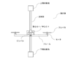
Claims (4)
前記フレームに対して所定の範囲で変位可能となるように前記フレームに接続部を介して取り付けられ、かつ下方に延びた第1支持部と、
前記第1支持部の下端に設けられた下側対象物と、
前記第1支持部の上端から上方に延びる第2支持部と、
前記第2支持部の上端に設けられた上側対象物とを備え、
前記フレームが水平状態に保たれ、かつ前記第1支持部が垂直状態に保たれているとき、前記接続部は、飛行体の重心又は中心から水平方向前方にオフセットした位置よりも垂直方向上方であって、第1支持部及び下側対象物の重心よりも上方に配置されている、
飛行体。 A motor for driving a plurality of rotors is provided, and a flight unit having a frame extending at least in the front-back direction ,
A first support portion attached to the frame via a connection portion so as to be displaceable within a predetermined range with respect to the frame, and extending downward;
A lower object provided at a lower end of the first support portion,
A second support portion extending upward from an upper end of the first support portion;
An upper object provided at an upper end of the second support portion,
When the frame is kept horizontal and the first support is kept vertical, the connection is located vertically above a position offset horizontally forward from the center of gravity or center of the vehicle. And being disposed above the center of gravity of the first support and the lower object,
Flying object.
前記第1支持部は、長手方向を有する棒状体として形成される、
飛行体。 The flying object according to claim 1,
The first supporting portion, Ru is formed as a rod-shaped body having a longitudinal,
Flying object.
前記第2支持部は、長手方向を有する棒状体として形成される、
飛行体。 A flying object according to claim 1 or claim 2,
The second support portion, Ru is formed as a rod-shaped body having a longitudinal,
Flying object.
前記フレームに前記第1支持部の上端を取付けるための取付部を備え、
前記取付部は、略逆U字形に形成され、
前記接続部は、略逆U字形の頂点付近に配置されている、
飛行体。 The flying object according to any one of claims 1 to 3 ,
A mounting portion for mounting an upper end of the first support portion to the frame,
The mounting portion is formed in a substantially inverted U-shape,
The connection portion is disposed near a vertex of a substantially inverted U-shape .
Flying object.
Priority Applications (1)
| Application Number | Priority Date | Filing Date | Title |
|---|---|---|---|
| JP2018060971A JP6661199B2 (en) | 2018-03-27 | 2018-03-27 | Flying object |
Applications Claiming Priority (1)
| Application Number | Priority Date | Filing Date | Title |
|---|---|---|---|
| JP2018060971A JP6661199B2 (en) | 2018-03-27 | 2018-03-27 | Flying object |
Related Child Applications (1)
| Application Number | Title | Priority Date | Filing Date |
|---|---|---|---|
| JP2020016804A Division JP7019204B2 (en) | 2020-02-04 | 2020-02-04 | Flying object |
Publications (3)
| Publication Number | Publication Date |
|---|---|
| JP2019171997A JP2019171997A (en) | 2019-10-10 |
| JP2019171997A5 JP2019171997A5 (en) | 2019-11-21 |
| JP6661199B2 true JP6661199B2 (en) | 2020-03-11 |
Family
ID=68166384
Family Applications (1)
| Application Number | Title | Priority Date | Filing Date |
|---|---|---|---|
| JP2018060971A Active JP6661199B2 (en) | 2018-03-27 | 2018-03-27 | Flying object |
Country Status (1)
| Country | Link |
|---|---|
| JP (1) | JP6661199B2 (en) |
Families Citing this family (5)
| Publication number | Priority date | Publication date | Assignee | Title |
|---|---|---|---|---|
| JPWO2021074985A1 (en) * | 2019-10-16 | 2021-04-22 | ||
| JP2021142782A (en) * | 2020-03-10 | 2021-09-24 | エアロセンス株式会社 | Flying body |
| WO2021240681A1 (en) * | 2020-05-27 | 2021-12-02 | 株式会社エアロネクスト | Rotary wing aircraft |
| WO2022176967A1 (en) * | 2021-02-17 | 2022-08-25 | 望月玲於奈 | Rotary mechanism, flight vehicle, and device and method for controlling attitude of load |
| JP2023110849A (en) * | 2021-11-09 | 2023-08-09 | 望月 玲於奈 | Rotation mechanism, flying object, device for controlling posture of load, and method |
Family Cites Families (10)
| Publication number | Priority date | Publication date | Assignee | Title |
|---|---|---|---|---|
| JP2013079034A (en) * | 2011-10-05 | 2013-05-02 | Zero:Kk | Rotorcraft for aerial photographing |
| JP6367522B2 (en) * | 2013-02-28 | 2018-08-01 | 株式会社トプコン | Aerial photography system |
| JP6261090B2 (en) * | 2015-05-18 | 2018-01-17 | 株式会社amuse oneself | Unmanned aerial vehicle |
| KR102018970B1 (en) * | 2015-05-19 | 2019-09-05 | 가부시키가이샤 에아로넥스트 | Rotorcraft |
| JP6283425B2 (en) * | 2015-09-11 | 2018-02-21 | エスゼット ディージェイアイ オスモ テクノロジー カンパニー リミテッドSZ DJI Osmo Technology Co., Ltd. | Unmanned aerial vehicle |
| JP2017173254A (en) * | 2016-03-25 | 2017-09-28 | 東京電力ホールディングス株式会社 | Radiation dosimetry device |
| JP6844097B2 (en) * | 2016-04-19 | 2021-03-17 | インダストリーネットワーク株式会社 | Drone flying object |
| WO2018003079A1 (en) * | 2016-06-30 | 2018-01-04 | 株式会社オプティム | Drone accessory control system, drone accessory control method, and program |
| MX2019001379A (en) * | 2016-08-18 | 2019-06-03 | Tevel Advanced Tech Ltd | Device, system and method for harvesting and diluting using aerial drones, for orchards, plantations and green houses. |
| US11325696B2 (en) * | 2016-10-03 | 2022-05-10 | Aeronext Inc. | Delivery rotary-wing aircraft |
-
2018
- 2018-03-27 JP JP2018060971A patent/JP6661199B2/en active Active
Also Published As
| Publication number | Publication date |
|---|---|
| JP2019171997A (en) | 2019-10-10 |
Similar Documents
| Publication | Publication Date | Title |
|---|---|---|
| US11780565B2 (en) | Rotary wing aircraft | |
| JP6661199B2 (en) | Flying object | |
| US11140322B2 (en) | Stabilizing platform | |
| US8794566B2 (en) | Vehicle capable of stabilizing a payload when in motion | |
| US20140034776A1 (en) | Vehicle capable of in-air and on-ground mobility | |
| JP7217543B2 (en) | A system that forms a two-degree-of-freedom actuator, e.g. to change the pitch angle of the blades of a propeller during rotation | |
| JP6085520B2 (en) | Remotely controlled unmanned air vehicle | |
| JP6694624B2 (en) | Rotorcraft | |
| JP7120645B2 (en) | rotorcraft | |
| US11628951B2 (en) | Electronic component and aircraft with electronic component attached thereto | |
| JP6661159B2 (en) | Rotorcraft | |
| CN110539892A (en) | Panorama shooting's unmanned aerial vehicle that takes photo by plane | |
| JP7083164B2 (en) | Rotorcraft | |
| JP7186474B2 (en) | flying object | |
| JP7108348B2 (en) | flying object | |
| JP7019204B2 (en) | Flying object | |
| JP6836815B2 (en) | Rotorcraft | |
| JP2020029257A (en) | Rotorcraft | |
| JP2024057082A (en) | Aircraft | |
| JP2007050841A (en) | Small rotary wing aircraft | |
| CN109987221B (en) | Unmanned aerial vehicle | |
| JP7466217B2 (en) | Take-off and Landing System |
Legal Events
| Date | Code | Title | Description |
|---|---|---|---|
| A521 | Request for written amendment filed |
Free format text: JAPANESE INTERMEDIATE CODE: A523 Effective date: 20191007 |
|
| A621 | Written request for application examination |
Free format text: JAPANESE INTERMEDIATE CODE: A621 Effective date: 20191007 |
|
| A871 | Explanation of circumstances concerning accelerated examination |
Free format text: JAPANESE INTERMEDIATE CODE: A871 Effective date: 20191007 |
|
| A975 | Report on accelerated examination |
Free format text: JAPANESE INTERMEDIATE CODE: A971005 Effective date: 20191016 |
|
| A131 | Notification of reasons for refusal |
Free format text: JAPANESE INTERMEDIATE CODE: A131 Effective date: 20191025 |
|
| A521 | Request for written amendment filed |
Free format text: JAPANESE INTERMEDIATE CODE: A523 Effective date: 20191212 |
|
| TRDD | Decision of grant or rejection written | ||
| A01 | Written decision to grant a patent or to grant a registration (utility model) |
Free format text: JAPANESE INTERMEDIATE CODE: A01 Effective date: 20200123 |
|
| RD04 | Notification of resignation of power of attorney |
Free format text: JAPANESE INTERMEDIATE CODE: A7424 Effective date: 20200204 |
|
| A61 | First payment of annual fees (during grant procedure) |
Free format text: JAPANESE INTERMEDIATE CODE: A61 Effective date: 20200204 |
|
| R150 | Certificate of patent or registration of utility model |
Ref document number: 6661199 Country of ref document: JP Free format text: JAPANESE INTERMEDIATE CODE: R150 |
|
| R250 | Receipt of annual fees |
Free format text: JAPANESE INTERMEDIATE CODE: R250 |
|
| R250 | Receipt of annual fees |
Free format text: JAPANESE INTERMEDIATE CODE: R250 |