JP7108348B2 - flying object - Google Patents
flying object Download PDFInfo
- Publication number
- JP7108348B2 JP7108348B2 JP2022009869A JP2022009869A JP7108348B2 JP 7108348 B2 JP7108348 B2 JP 7108348B2 JP 2022009869 A JP2022009869 A JP 2022009869A JP 2022009869 A JP2022009869 A JP 2022009869A JP 7108348 B2 JP7108348 B2 JP 7108348B2
- Authority
- JP
- Japan
- Prior art keywords
- aircraft
- flight
- center
- flying object
- flying
- Prior art date
- Legal status (The legal status is an assumption and is not a legal conclusion. Google has not performed a legal analysis and makes no representation as to the accuracy of the status listed.)
- Active
Links
Images


Description
本発明は、飛行体に関する。 The present invention relates to aircraft.
近年、小型、軽量で操縦が簡単であり、風の影響が少なく、安定した姿勢を維持するこ
とが可能な飛行体が提案されている(例えば、特許文献1)。
In recent years, flying objects have been proposed that are small, lightweight, easy to maneuver, less affected by wind, and capable of maintaining a stable attitude (for example, Patent Document 1).
また、複数の回転翼を有する飛行体が水平方向を含む方向に進行する場合に、進行方向
前方及び後方の各回転翼の回転数の差を小さくすることができる飛行体が提案されている
(例えば、特許文献2)。
In addition, when an aircraft having a plurality of rotor blades travels in a direction including the horizontal direction, an aircraft has been proposed that can reduce the difference in the number of rotations of the rotor blades on the front and rear sides of the flight direction ( For example, Patent Document 2).
従来の飛行体は、タワーマンション間、高層ビル間において発生する横風等の気流を受
けて、横揺れする。この横揺れによって、上記飛行体は、その飛行態勢を崩して傾斜する
。そして、上記飛行体は、横揺れを原因として、タワーマンション、高層マンションの敷
地内から大きく外れて、当該敷地の外側領域を飛行する。
Conventional flying objects sway due to air currents such as side winds generated between high-rise apartment buildings and high-rise buildings. Due to this rolling, the flying object loses its flight attitude and tilts. Then, due to the rolling motion, the flying object largely deviates from the premises of the tower condominium or the high-rise condominium and flies in the outer area of the premises.
通常、上記飛行体がタワーマンション、高層マンションの敷地の外側を飛行した場合に
は、当該飛行体に取り付けられている繋留ロープを引くことにより、その飛行態勢を元に
戻すことを試みる。しかしながら、上記飛行体が備えている繋留ロープを引くことにより
、上記飛行体の飛行態勢は、さらに悪化する。最終的には、上記飛行体は、飛行態勢を崩
して、タワーマンション、高層マンションの敷地内から大きく外れて、当該敷地の外側領
域を飛行した後、当該敷地の外側領域に墜落してしまう。また、飛行体に搭載されている
GPS装置が飛行中に途絶となった場合には、制御不能となり、当該飛行体は、タワーマ
ンション、高層マンションの敷地内から当該敷地外へと飛行してしまう。
Usually, when the flying object flies outside the premises of a high-rise apartment building, an attempt is made to restore the flight posture by pulling the mooring rope attached to the flying object. However, pulling on the tethering rope provided by the vehicle further deteriorates the flight attitude of the vehicle. Ultimately, the flying object loses its flight posture, deviates greatly from the premises of the tower apartment or high-rise apartment, flies in the outer area of the premises, and then crashes in the outer area of the premises. In addition, if the GPS device mounted on the flying object is interrupted during flight, the flying object becomes uncontrollable and the flying object flies from the premises of the tower condominium or high-rise condominium to the outside of the premises. .
さらに、従来の飛行体の着陸時において、当該飛行体が備えている回転翼を駆動するモ
ータの回転を停止すると、当該回転翼を備えたフライト部は、水平を保持することができ
ない。このため、上記飛行体のフライト部は、傾斜することになる。上記飛行体のフライ
ト部が傾斜することによって、当該飛行体は、当該飛行体の姿勢を保つことができず、転
倒してしまう。
Furthermore, when a conventional flying object lands, if the rotation of the motor that drives the rotor blades of the flying object is stopped, the flight section equipped with the rotor blades cannot be kept horizontal. As a result, the flight portion of the aircraft is inclined. When the flight portion of the flying object inclines, the flying object cannot maintain its attitude and overturns.
また、従来の飛行体は、当該飛行体が備えている回転翼と対象物を撮影するために必要
なカメラの位置が近接しているため、撮影時にカメラの画面に飛行体の回転翼等が映り込
んでしまう事態が発生する。カメラの画面に飛行体の回転翼等が映り込んでしまうと、対
象物を十分に撮影することができないばかりでなく、対象物を動画撮影する場合には、そ
れまで撮影した画像の価値を無くしてしまう。
In addition, since the position of the camera necessary for photographing the target object is close to the rotor blades of the conventional flying object, the rotor blades of the flying object, etc. appear on the camera screen when photographing. A situation occurs where it is reflected. If the rotor blades of an aircraft are reflected on the camera screen, it will not only be impossible to adequately photograph the object, but also, if the object is to be filmed as a video, the value of the previously photographed images will be lost. end up
また、従来の飛行体は、タワーマンション間、高層ビル間において発生する横風等の気
流を受けて、横揺れする。この場合には、上記飛行体は、その回転翼の一方を傾けた状態
でホバリングをする。ホバリングをしている状態は、回転翼が傾いた状態であるので、飛
行体が撮影を行うと、上記回転翼が撮影の障害物となり、カメラの画面に飛行体の回転翼
が映り込んでしまうという問題点を有する。
In addition, conventional flying objects are subject to air currents such as side winds generated between high-rise apartment buildings and high-rise buildings, and sway. In this case, the aircraft hovers with one of its rotors tilted. When the flying object is hovering, the rotor blades are tilted, so when the flying object takes a picture, the rotor blades become an obstacle to the shooting, and the rotor blades of the flying object are reflected on the camera screen. There is a problem.
そこで、本発明の目的は、より安定した飛行姿勢を保つ飛行体を提供することを目的と
する。
SUMMARY OF THE INVENTION Accordingly, an object of the present invention is to provide a flying object that maintains a more stable flight attitude.
本発明によれば、複数の回転翼及び前記回転翼を駆動させるモータを少なくとも備えた
飛行部と、
対象物を積載可能な積載部と、
前記飛行部と前記積載部とを互いに変位可能に接続する接続部と、
を備えた飛行体が得られる。
According to the present invention, a flight section including at least a plurality of rotor blades and a motor for driving the rotor blades;
a loading unit capable of loading an object;
a connecting portion connecting the flying portion and the loading portion to each other so as to be displaceable;
is obtained.
本発明によれば、飛行体の飛行部、積載部及び接続部の位置関係を工夫したことにより
、より安定した飛行性能を有する飛行体を提供することができる
According to the present invention, it is possible to provide an aircraft having more stable flight performance by devising the positional relationship among the flight section, the loading section, and the connection section of the aircraft.
本発明の実施形態の内容を列記して説明する。本発明の実施の形態による飛行体は、以
下のような構成を備える。
[項目1]
複数の回転翼及び前記回転翼を駆動させるモータを少なくとも備えた飛行部と、
対象物を積載可能な積載部と、
前記飛行部と前記積載部とを互いに変位可能に接続する接続部と、
を備えた飛行体。
[項目2]
項目1に記載の飛行体であって、
前記接続部は、前記飛行部の重心又は中心よりも上方にある、
飛行体。
[項目3]
項目2に記載の飛行体であって、
前記接続部は、前記飛行部の重心又は中心よりも鉛直方向において真上又は略真上にあ
る、
飛行体。
[項目4]
項目1に記載の飛行体であって、
前記接続部は、前記飛行部の重心又は中心と一致又は略一致している、
飛行体。
[項目5]
項目1に記載の飛行体であって、
前記接続部は、前記飛行部の重心又は中心よりも下方にある、
飛行体。
[項目6]
項目5に記載の飛行体であって、
前記接続部は、前記飛行部の重心又は中心よりも鉛直方向において真下又は略真下にあ
る、
飛行体。
[項目7]
項目1に記載の飛行体であって、
前記接続部は、前記飛行体の重心又は中心よりも水平方向において異なる位置にある、
飛行体。
[項目8]
項目1乃至項目7のいずれかに記載の飛行体であって、
前記接続部は、前記積載部の重心又は中心にある、
飛行体。
[項目9]
項目1に記載の飛行体であって、
前記接続部が二軸以上の回動軸を備えている、
飛行体。
[項目10]
項目1又は項目2に記載の飛行体であって、
前記積載部がその長さを伸長させるための調節機構を備えていることを特徴とする飛行
体。
[項目11]
複数の回転翼と、
前記複数の回転翼を支持するアーム部と、
物体を搭載する搭載部と、
前記搭載部が所定の範囲で移動可能な状態で当該搭載部を前記アーム部に接続する接続
部とを備え、
前記接続部の位置が、当該アーム部の重心よりも上にある、
飛行体。
[項目12]
項目11に記載の飛行体であって、
前記接続部が二軸ジンバル構造を備えている、
飛行体。
[項目13]
項目11又は項目12に記載の飛行体であって、
前記搭載部がその長さを伸長させるための調節機構を備えていることを特徴とする飛行
体。
[項目14]
項目1乃至項目13のいずれかに記載の飛行体であって、
前記搭載部にロープが取り付けられている、
飛行体。
[項目15]
項目1乃至項目4のいずれかに記載の飛行体であって、
前記接続部の位置が、前記複数の回転翼が回転することによって機体に発生する揚力の
当該飛行体に対する作用点よりも上にある、
飛行体。
[項目16]
項目1乃至項目5のいずれかに記載の飛行体であって、
前記接続部の位置が、当該飛行体の重心よりも上にある、
飛行体。
The contents of the embodiments of the present invention are listed and explained. An aircraft according to an embodiment of the present invention has the following configuration.
[Item 1]
a flight section including at least a plurality of rotor blades and a motor for driving the rotor blades;
a loading unit capable of loading an object;
a connecting portion connecting the flying portion and the loading portion to each other so as to be displaceable;
Air vehicle with
[Item 2]
The aircraft according to
the connecting portion is above the center of gravity or the center of the flying portion;
Airplane.
[Item 3]
The aircraft according to
The connecting portion is vertically above or substantially above the center of gravity or the center of the flying portion.
Airplane.
[Item 4]
The aircraft according to
the connecting portion coincides or substantially coincides with the center of gravity or the center of the flight portion;
Airplane.
[Item 5]
The aircraft according to
the connecting portion is below the center of gravity or center of the flying portion;
Airplane.
[Item 6]
The aircraft according to
The connecting portion is located directly below or substantially below the center of gravity or the center of the flying portion in the vertical direction,
Airplane.
[Item 7]
The aircraft according to
the joint is at a different position in the horizontal direction than the center of gravity or center of the aircraft;
Airplane.
[Item 8]
The aircraft according to any one of
the connecting portion is at the center of gravity or center of the loading portion;
Airplane.
[Item 9]
The aircraft according to
wherein the connection portion has two or more rotation shafts,
Airplane.
[Item 10]
The aircraft according to
An aircraft characterized in that said payload includes an adjustment mechanism for extending its length.
[Item 11]
a plurality of rotor blades;
an arm portion that supports the plurality of rotor blades;
a mounting portion for mounting an object;
a connecting portion that connects the mounting portion to the arm portion in a state in which the mounting portion is movable within a predetermined range;
the position of the connection portion is above the center of gravity of the arm portion;
Airplane.
[Item 12]
12. The aircraft according to item 11,
wherein the connecting portion comprises a biaxial gimbal structure;
Airplane.
[Item 13]
The aircraft according to item 11 or item 12,
An aircraft, wherein said mounting portion is provided with an adjustment mechanism for extending its length.
[Item 14]
14. The aircraft according to any one of
A rope is attached to the mounting portion,
Airplane.
[Item 15]
The aircraft according to any one of
The position of the connecting portion is above a point of action of the lift generated on the airframe by the rotation of the plurality of rotor blades on the aircraft.
Airplane.
[Item 16]
The aircraft according to any one of
the position of the connecting portion is above the center of gravity of the aircraft;
Airplane.
<実施形態1>
以下、適宜図面を参酌しながら、本発明の飛行体1について説明する。
<
Hereinafter, the flying
(飛行体の基本構造)
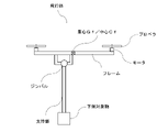
図1乃至図4に示されるように、本発明の実施の形態による飛行体は、プロペラと、当
該プロペラを回転させるためのモータと、フレームとを備える飛行部と、支持部と当該支
持部の両端に設けられた上側対象物及び下側対象物とを備える積載部とを備えている。
(Basic structure of flying object)
As shown in FIGS. 1 to 4, a flying object according to an embodiment of the present invention includes a flying section including a propeller, a motor for rotating the propeller, and a frame, a support section, and a support section. A loading section with an upper object and a lower object provided at opposite ends.
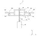
図2に示される飛行体において、本実施の形態によるジンバル(接続部)は、飛行部と
積載部とが水平方向(X軸及びY軸)において変位可能に互いに接続するものである。
In the flying object shown in FIG. 2, the gimbal (connecting part) according to the present embodiment connects the flying part and the loading part so that they can be displaced in the horizontal direction (X-axis and Y-axis).
図3に示される飛行体において、ジンバルは、積載部の重心Gr又は中心Crと一致又
は略一致している。なお、図示される図は、積載部の重心と中心が一致している場合を示
しているが、上側対象物と下側対象物との重量や形状等が異なる場合には、重心Grと中
心Crとは必ずしも一致するとは限らない。この場合でも、ジンバルは、重心Grと一致
又は略一致する位置に設けられる。
In the aircraft shown in FIG. 3, the gimbal coincides or substantially coincides with the center of gravity Gr or center Cr of the loading section. The illustrated drawing shows the case where the center of gravity of the loading unit and the center of the stacking unit are aligned. Cr does not always match. Even in this case, the gimbal is provided at a position that coincides or substantially coincides with the center of gravity Gr.
図5に示される飛行体において、ジンバルは、飛行部の重心Gf又は中心Cfよりも上
方にある。
In the flight vehicle shown in FIG. 5, the gimbal is above the center of gravity Gf or center Cf of the flight section.
かかる構成によれば、図示されている例においては、例えば、ユーザが図の左方向から
下側対象物をハンドキャッチによりつかんだ場合、飛行部がユーザがから離れる方向に傾
くこととなり、プロペラによる回転からユーザを守ることができる。
According to such a configuration, in the illustrated example, for example, when the user grabs the lower object from the left side of the figure with a hand catch, the flying part tilts in the direction away from the user, and the propeller It can protect the user from rotation.
図6に示される飛行体において、ジンバルは、飛行部の重心Gf又は中心Cfよりも鉛
直方向において真上又は略真上にある。
In the flying object shown in FIG. 6, the gimbal is vertically above or substantially above the center of gravity Gf or center Cf of the flight section.
かかる構成によれば、停止時であっても、やじろべえと同様の原理によって、飛行部は
セルフレベリングすることができる。
According to such a configuration, the flying part can be self-leveled by the same principle as a bull's-eye even when it is stopped.
図7に示される飛行体において、ジンバルは、飛行部の重心Gf又は中心Cfと一致又
は略一致している。
In the flying object shown in FIG. 7, the gimbal coincides or substantially coincides with the center of gravity Gf or center Cf of the flight section.
かかる構成によれば、飛行部が風にあおられた場合や急旋回した場合であっても、飛行
部は、重心を中心として回転することから、飛行部の変位は積載部の変位に影響しない。
According to this configuration, even if the flying section is blown by the wind or makes a sharp turn, the flying section rotates around the center of gravity, so the displacement of the flying section does not affect the displacement of the loading section. .
図8に示される飛行体において、ジンバルは、飛行部の重心Gf又は中心Cfよりも下
方にある。
In the flight vehicle shown in FIG. 8, the gimbal is below the center of gravity Gf or center Cf of the flight section.
図9に示される飛行体において、ジンバルは、飛行部の重心Gf又は中心Cfよりも鉛
直方向において真下又は略真下にある。
In the flying object shown in FIG. 9, the gimbal is located directly below or substantially below the center of gravity Gf or center Cf of the flight section in the vertical direction.
図10に示される飛行体は、ジンバルは、飛行体の重心Gf又は中心Cfよりも水平方
向において異なる位置にある。かかる構成によれば、例えば、給電ケーブル等を下側対象
物に取り付けた場合、当該ケーブルを引っ張った場合に、飛行部は左に傾く(すなわち、
左側のプロペラが右側のプロペラよりも下方に来るように傾く)。よって、ユーザの手元
に戻るように誘導させることがでる。
In the aircraft shown in FIG. 10, the gimbal is at a different position in the horizontal direction than the center of gravity Gf or center Cf of the aircraft. According to such a configuration, for example, when a power supply cable or the like is attached to the lower object, when the cable is pulled, the flying part inclines to the left (that is,
Lean so that the left propeller is lower than the right propeller). Therefore, it can be guided to return to the user's hand.
図11に示されるように、本実施の形態によるジンバルは、飛行部の重心Gr又は飛行
部の中心Crから所定距離を半径とする仮想球Sの範囲内に位置している。
As shown in FIG. 11, the gimbal according to the present embodiment is positioned within a virtual sphere S having a radius of a predetermined distance from the center of gravity Gr or the center Cr of the flying section.
本実施の形態によるジンバルは、二軸の回動軸を備えるに軸ジンバルである。 The gimbal according to this embodiment is a monoaxial gimbal having two pivot shafts.
なお、積載部の支持部は、その長さを伸長させるための調節機構を備えていることであ
ってもいい。
In addition, the supporting portion of the loading portion may be provided with an adjusting mechanism for extending its length.
図12乃至図17は、上述した図5乃至図11に示した構造のうち、上側対象物と、当
該上側対象物を支持するための支持部をなくした構造である。
FIGS. 12 to 17 show structures in which the upper object and the supporting portion for supporting the upper object are eliminated from the structures shown in FIGS. 5 to 11 described above.
図から理解されるように、図12乃至図17に示されるジンバルは、積載部の重心には
ない。即ち、ジンバルは、積載部の重心とは異なる位置に設けられている。
As can be seen, the gimbal shown in Figures 12-17 is not at the center of gravity of the payload. That is, the gimbal is provided at a position different from the center of gravity of the loading section.
図18に示される飛行体において、ジンバルは、積載部の重心に設けられている。また
、ジンバルは水平方向において飛行部の重心又は中心とは異なる位置に設けられている。
In the aircraft shown in FIG. 18, the gimbal is provided at the center of gravity of the loading section. In addition, the gimbal is provided at a position different from the center of gravity of the flight section in the horizontal direction.
かかる構成によれば、上側対象物と下側対象物とをカメラ等とすることにより、橋梁検
査に適した構成とすることができる。
According to this configuration, by using cameras or the like as the upper and lower objects, a configuration suitable for bridge inspection can be achieved.
図19は、図18におけるジンバル飛行部の重心Gr又は中心Crよりも情報に設けた
ものである。
FIG. 19 provides more information than the center of gravity Gr or center Cr of the gimbal flight section in FIG.
以下、上述した実施の形態による構造のうち、一部の実施例について例示して説明する
。
Some examples of the structures according to the above-described embodiments will be illustrated and described below.
図210は、本発明の飛行体1の概要を示した斜視図である。図210に示されるよう
に飛行体1は、複数の回転翼部10A~10Dを備えている。回転翼部10A~10Dは
、回転翼12A~12Dと動力部14A~14Dからなる。回転翼12A~12Dは、動
力部14A~14Dを駆動源として、所定方向に回転をする。動力部14A~14Dとし
ては、回転翼12A~12Dを駆動することができるものであれば、特に制限されるもの
ではなく、例えば、電気モータ、小型エンジン等を挙げることができる。なお、本発明の
飛行体が備えている回転翼部10の個数は、特に制限されるものではなく、適宜設定する
ことができる。実施形態1においては、4個の回転翼部を備えた飛行体1を一例として説
明する。
FIG. 210 is a perspective view showing an outline of the
飛行体1は、複数の回転翼部10A~10Dを支持する複数のアーム部16A~16D
と、フライト部18のベースである円環形状のフライト部材162と、フライト部材18
の下方に設けられた撮影部20と、フライト部材18と撮影部20とを連結するための支
持部材30を備えている。フライト部材18と撮影部20とは、支持部材30の下端部3
4を介して連結されている。撮影部20は、収納ボックス22と撮影用カメラ本体26か
らなり、収納ボックス22は、撮影用カメラ本体26を収納するためにボックス形状を有
している。
The
, an
and a
4 are connected. The photographing
図210に示された飛行体1において、支持部材30の下方端部34は、ボックス形状
を有する撮影部20の上面に設置された収納ボックス取付け部24と連結している。飛行
体1は、上記撮影部20の下面から連通し、ボックス形状を有する撮影部20の内部にお
いて、撮影用カメラ本体22を固定するための固定用支持部材28を有している。支持部
材30と固定用支持部材28は、同一の直線上に位置している。
In the
固定用支持部材28の端部282には、飛行体1の飛行位置及び飛行形態を制御するた
めの繋留ロープ60が取り付けられている。繋留ロープ60は、いわゆる「凧の脚」と同
様に、飛行体1の飛行状態を安定化させる。飛行体1が安定して飛行することによって、
撮影部20を水平に保持することができる。
飛行体1は、タワーマンション、高層マンション等の展望撮影に最も適しており、タワー
マンション、高層マンション等の敷地内の上空において、飛行することが前提となってい
る。このため、繋留ロープ60は、飛行体1がタワーマンション、高層マンション等の敷
地外の上空へ飛行することを回避する観点から設けられている。なお、繋留ロープ60を
取り付ける形態は、撮影部20の下方に取り付けられるものであれば、その形態は、特に
制限されない。例えば、固定用支持部材28の端部282を介することなく、撮影部20
の底面に直接取り付けてもよい。
A
The
The flying
may be attached directly to the bottom of the
飛行体1は、回転翼部10A~10Dを支持するアーム部16A~16Dを備えている
。実施形態1において、フライト部18を構成するアーム部16は、アーム部16A~1
6Dの4本を備えているが、アーム部16の本数はこれに限定されない。例えば、飛行体
1のアーム部16として、6本、8本、10本、12本等のアーム部を適宜設けてもよい
。飛行体1が安定して飛行して、かつ重量が大きく、精度の高いカメラを搭載する場合に
は、回転翼部10の個数に合せて、例えば、アーム部16の数を6本以上としてもよい。
The
6D, but the number of
図210において、4本のアーム部16A~16Dは、円環形状において等間隔となる
ように4方向に設けられている。すなわち、4本のアーム部16A~16Dは、隣接する
アーム部の間隔が、90°となるように設けられている。なお、アーム部16A~16D
は、直線形状を有していても、設計上の観点から直線形状を基調として、折れ曲がった形
状を有していてもよい。
In FIG. 210, the four
may have a linear shape, or may have a bent shape based on a linear shape from a design point of view.
アーム部16A~16Dは、支持部材30の外周に設けられたリングRを中心として外
側に向かって、等間隔にて延伸している。支持部材30は、リングRを連通して、上方向
に延伸している。支持部材30の上方端部32は、フライト部18と支持部材30とを接
続するための接続部40を有している。
The
図21は、実施形態1の飛行体1を真上から見た概略図である。図21に示されるよう
に、飛行体1は、複数のアーム部16A~16Dの回転翼部10A~10D側の底面端部
をフライト部材162によって連結させた構造を有していてもよい。複数のアーム部16
A~16Dの端部に位置する回転翼部10A~10Dをフライト部材162によって連結
すると、隣接する回転翼部10A~10Dが繋がって、飛行体1の真上から見たフライト
部材162の外観形状は、円環形状となる。
FIG. 21 is a schematic diagram of the
When the
フライト部材162の形状は、隣接する回転翼部10を連結することができるものであ
れば、特に限定されるものではなく、円環形状、楕円形状、矩形状の枠体であってもよい
。アーム部16の端部に位置する回転翼部10をフライト部材162により連結すること
によって、フライト部18は、構造上より安定する。なお、フライト部材162の外側側
面には、飛行体1が夜間飛行する際に目印となる発光ダイオード等の発光体164を設け
ていてもよい。
The shape of the
図21に示された飛行体1は、飛行体1は、支持部材30の上方端部32に設置された
接続部40を通って、対向するフライト部材162上の部分を接続部40と橋架けするた
めの連結部材50を備えている。連結部材50は、支持部材30の支持部材上端32に設
けられている接続部40と同期して駆動する。接続部40が駆動することによって、連結
部材50は傾斜又は回転する。連結部材50は、フライト部10と連結しているので、接
続部40が駆動することによってフライト部10が傾斜又は回転する。フライト部10は
、接続部40が駆動する方向、大きさに依拠して、傾斜又は回転をする。飛行体1は、支
持部材30を中心にフライト部10を傾斜又は回転することができる。
具体的には、飛行体1は、回転翼部10Aと回転翼部10Dとの中間に設定されたフラ
イト部材18の中間点181と、回転翼部Bと回転翼部Cとの中間に設定されたフライト
部材18の中間点182とを橋架けする連結部材50を備えている。連結部材50は、支
持部材30の上方端部32に設けられた接続部40を通過しているので、フライト部18
は、接続部40が駆動することによって、接続部40を頂点として傾斜することができる
。同様に、フライト部18は、接続部40が駆動することによって、接続部40を頂点と
して回転することもできる。
Specifically, the flying
can tilt with the connecting
接続部40は、フライト部10を傾斜又は回転することができる機構であれば、特に制
限されるものではない。飛行体の機能に応じて、適宜設定することができる。例えば、接
続部40として、一軸ジンバル構造、二軸ジンバル構造、三軸ジンバル構造を採用しても
よい。なお、上記ジンバル構造には、モータ等の駆動装置を設けてもよいし、設けなくて
もよい。
The connecting
本発明の飛行体をタワーマンション、高層マンション等の眺望撮影を目的とする飛行体
として採用する場合には、その飛行態様は、主に垂直上昇用であるので、接続部40を二
軸ジンバル構造とすればよい。接続部40が駆動することによって、連結部材50を傾斜
させることができ、回転させることもできる。連結部材50が傾斜又は回転することによ
って、連結部材50と連結しているフライト部18は、傾斜又は回転する。フレーム18
が傾斜又は回転することによって、フライト部18に搭載されている回転翼12A~12
Dは、傾斜又は回転することができる。
When the flying object of the present invention is used as a flying object for the purpose of photographing the view of tower apartments, high-rise apartments, etc., the flight mode is mainly for vertical ascent, so the connecting
By tilting or rotating, the
D can be tilted or rotated.
図22は、飛行体1の側面図である。飛行体1の技術的特徴は、支持部材30の上方端
部32に接続部40を備えており、フライト部18は、接続部40を頂点として傾斜又は
回転することができ、接続部40が、複数の回転翼12A~12Dが回転することによっ
て前記飛行体に発生する揚力の中心点Uよりも上方に位置することにある。図22に示さ
れる飛行体1において、支持部材30は、連結部材50と重なっている。このため、図2
2に示される飛行体1においては、連結部材50と支持部材30とが同一直線上に存在し
ている。
22 is a side view of the
2, the connecting
図22に示されるように、接続部40(1)は、複数の回転翼12A~12Dが回転す
ることによって飛行体に発生する揚力の中心点U(2)よりも上方に位置している。従来
の飛行体は、フライト部と支持部材との接続部が、複数の回転翼が回転することによって
飛行体に発生する揚力の中心点U(2)と一致しているか、又は、飛行体に発生する揚力
の中心点U2)よりも低い位置に設定されている。
As shown in FIG. 22, the connecting portion 40(1) is located above the center point U(2) of the lift force generated in the aircraft by the rotation of the plurality of
本発明の飛行体は、接続部40の中心点Gと飛行体に発生する揚力の中心点Uとが上記
位置関係を採用することによって、飛行体1が飛行時に横風等の強風を受けた場合であっ
ても、上記飛行体1に取り付けられた繋留ロープ60を引くことによって、飛行態勢を立
て直して、元の飛行状態に戻すことができる。
The flying object of the present invention adopts the above-described positional relationship between the center point G of the
一方、従来の飛行体は、フライト部18と支持部材30との接続部40の重心点Gが飛
行体1に発生する揚力の中心点Uよりも下方に位置している。このため、従来の飛行体は
、横風等の強風を受けて飛行態勢を崩した態勢から、当該態勢を元に戻すために飛行体の
繋留ロープを引いても、下向きの力がさらに加えられる。その結果、従来の飛行体は、横
風等の強風を受けて飛行態勢を崩した態勢からさらに当該飛行体の飛行態勢を悪化させる
。最終的には、従来の飛行体は、高層マンション等の敷地内の上空範囲を出て、当該敷地
外の上空を飛行し、高層階から落下する場合もある。
On the other hand, in the conventional flying object, the center of gravity G of the connecting
(飛行体の飛行態様)
図24は、飛行体1の飛行態様を示したモデル図である。図24に基づいて、実施形態
1の飛行体1の飛行態様について説明する。飛行体1の飛行態様を(a)タワーマンショ
ン、高層マンション等の敷地内の地上を出発地点とした離陸する工程、(b)垂直に上昇
して飛行を開始し、タワーマンション、高層マンション等の高層階を撮影する工程、(c
)高層階を撮影した後、着陸する工程とに分けて説明する。
(Flight Mode of Aircraft)
FIG. 24 is a model diagram showing the flight mode of the
) After photographing the upper floors, the process of landing will be explained separately.
(a)タワーマンション等の敷地内の地上を出発地点とした離陸する工程
図24(a)に示されるように、タワーマンション、高層マンション等の敷地内の出発
地において、飛行体1の撮影部20を構成する収納ボックス22には、撮影用カメラ本体
26が搭載されている。飛行体1の操縦者は、操作部を備えたラジオコントロール用の送
信機を操作して、回転翼部10A~10Dの動力部14A~14Dの出力を上昇させて、
回転翼12A~12Dの回転数を増加させる。回転翼12A~12Dが回転することによ
って、飛行体1を浮上させるために必要な揚力が鉛直上向きに発生する。当該揚力が、飛
行体1に働く重力を超えると飛行体1は、地面を離れて出発地を離陸する。なお、フライ
ト部18において対向する回転翼は、同じ向きに回転している。具体的に飛行体1におい
ては、回転翼12Aと回転翼12Cは左向きに回転し、回転翼12Bと回転翼12Dは右
向きに回転する。
(a) Process of taking off from the ground within the premises of a high-rise condominium, etc. As shown in Fig. 24(a), the photographing unit of the
The rotational speeds of the
(b)垂直に上昇して飛行を開始し、タワーマンション、高層マンション等の高層階を撮
影する工程
図24(b)に示されるように、飛行体1は、回転翼12A~12Dの回転数を増加さ
せることによって、タワーマンション、高層マンション等の敷地内において、上空に向か
って、垂直に上昇する。その後、飛行体1は、上昇を続けて、一定の高度に到達する。一
定の高度に到達した飛行体1は、当該高度において、空中停止(ホバリング)を行う。当
該高度は、飛行体1の飛行ルート、タワーマンション、高層マンション等の建築物の高さ
、飛行体1に適用される航空法等によって、適宜決定される。操縦者は、種々の条件を勘
案して、飛行体1が空中停止(ホバリング)を行う高度をあらかじめ設定しておいてもよ
い。
(b) The process of ascending vertically and starting flight, and photographing high-rise apartment buildings such as tower apartments, high-rise apartments, etc. As shown in FIG. By increasing , it rises vertically toward the sky in the premises of tower apartments, high-rise apartments, and the like. After that, the flying
飛行体1にかかる重量と、回転翼12A~12Dの回転によって、飛行体1に発生して
いる揚力とが力学的に釣り合っているため、当該飛行体は、空中停止(ホバリング)する
ことができる。回転翼12A~12Dの回転数は、一定レベルに維持されている。空中停
止(ホバリング)は、飛行体1が撮影用カメラ本体26を用い、タワーマンション、高層
マンション等の撮影を開始するために行われる。
Since the weight applied to the flying
図24(b)に示されるように、飛行体1が空中停止(ホバリング)している状態から
当該高度において水平移動する場合には、フライト部18を傾斜させる。飛行体1が水平
移動する場合には、フライト部18を構成する回転翼12A~12Dの回転数がほぼ同一
となるように調整する。飛行体1は、当該高度を保持しながら、水平移動した位置におい
て、撮影を開始することができる。飛行体1は、所定の高度において空中停止(ホバリン
グ)をしながら、所定の位置において、タワーマンション、高層マンション等の高層階を
撮影する。また、飛行体1は、必要に応じて、水平方向に飛行し、撮影位置を変えること
ができる。また、飛行体1は、垂直方向に飛行し、撮影位置を変えることができる。
As shown in FIG. 24(b), when the flying
(c)高層階を撮影した後、着陸する工程
図24(c)に示されるように、飛行体1は、タワーマンション、高層マンション等の
敷地内の目的地に着陸する。図24(c)において、目的地は地表であってもよいし、タ
ワーマンション、高層マンション等に設けられた飛行体1専用のヘリポートであってもよ
い。飛行体1は、目的地上空において回転翼12A~12Dの回転数を減少させる。飛行
体1は、高度を低下させて、着陸態勢に入る。飛行体1が着陸態勢に入る場合には、フラ
イト部18は地表に対して水平に維持される。フライト部18が傾斜している場合には、
当該フライト部18が地表に対して水平となるように回転翼12A~12Dの回転数を調
整する。
(c) Step of Landing after Photographing High-rise Floors As shown in FIG. 24(c), the flying
The rotation speeds of the
飛行体1は、着陸直前にフライト部18の回転翼12A~12Dの回転を停止する。回
転翼12A~12Dの回転を停止することによって、フライト部18は、それ自身の自重
によって、地表に対して水平となる。具体的には、図24(c)に示された飛行体1は、
破線で示されたようにフライト部分18が傾いた状態から、回転翼部12A~12Dが無
通電状態となることにより、実線で示されたように実線で示されたようにフライト部分1
8が水平な状態となる。回転翼12A~12Dは、重力の影響により、自然に水平となる
。このように、本発明の飛行体1は、支持部材30の上方端部32にフライト部18との
接続部40を設けているので、飛行体1が着陸直前に無通電状態となった場合にフライト
部18が水平となることにより、安定した着陸状態を確保することができる。
The
From the state in which the
8 is horizontal. The
このように、実施形態1の飛行体1は、タワーマンション、高層マンション等の敷地内
において安定した飛行を確保することができ、撮影用カメラ本体26の撮影時のブレが少
ないため、夜景撮影にも好適に用いることができる。実施形態1の飛行体1は、当該飛行
体が空中停止(ホバリング)している限りは、撮影部20を水平に保持することができ、
撮影部20は大きく揺れることがない。このため、飛行体1は、夜景撮影に必要なシャッ
ター速度にも十分対応することができる。
As described above, the flying
The
<実施形態2>
実施形態2の飛行体2は、当該飛行体に発生する揚力の中心点Uと、支持部材30と撮
影部20との重力の作用点Gが一致していることを特徴としている。飛行体2は、上記揚
力の中心点Uと重力の作用点Gとが一致するように設計されているので、支持部材30と
撮影部20による重力による回転モーメントが発生しない。このため、実施形態2の飛行
体2においては、水平方向に進行する場合において、進行方向に対して前方の回転翼の回
転数と後方の回転翼の回転数とをほぼ等しくすることができる。
<
The flying
飛行体2は、繋留ロープの係留地点からほぼ垂直に上昇し、狭い範囲でホバリングしな
がら長時間の撮影に適したものである。さらに、飛行体2は、タワーマンション、高層マ
ンション等の敷地内を水平方向に移動する場合には、利便性がさらに向上する。すなわち
、飛行体2は、タワーマンション、高層マンション等の眺望撮影に適したものであり、繋
留ロープの係留地点から垂直(直上)に飛行することを基本動作とする。しかしながら、
飛行体2がタワーマンション、高層マンション等の周囲を撮影する場合、外壁検査等を行
う場合には、垂直(直上)に飛行することのみならず、水平方向に飛行することも必要と
なる。飛行体2が水平方向に飛行する場合には、フライト部18を傾斜させなければなら
ない。
The flying
When the flying
実施形態2の飛行体2は、水平方向に進行するためにフライト部18を傾斜しなければ
ならない場合であっても、進行方向に対して前方の回転翼の回転数と後方の回転翼の回転
数とをほぼ等しくできることによって、回転翼12A~12Dを駆動するための動力部1
4A~14Dの出力を抑制することができる。
Even if the
Outputs of 4A to 14D can be suppressed.
<実施形態3>
実施形態3の飛行体3は、支持部材30が当該支持部材30の長さを伸長させるための
調節機構を備えている。調節機構は、支持部材30の外周に設けられたアーム部16A~
16Dと係合するリングRを基準として、上部に設けられていても、下部に設けられてい
てもよい。調節機構は、支持部材30の長さを伸長する。
<Embodiment 3>
The aircraft 3 of Embodiment 3 has an adjustment mechanism for extending the length of the
With reference to the ring R that engages with 16D, it may be provided above or below. The adjustment mechanism extends the length of
飛行体3がタワーマンション、高層ビル等の敷地内において、着陸する場合には、上記
調節機構によって、鉛直下向きに支持部材30を伸長する。鉛直下向きに支持部材30を
伸長することによって、飛行体3の重心が下方に移動し、安定した着陸状態を確保するこ
とができる。
When the flying object 3 lands on the site of a high-rise apartment building, high-rise building, or the like, the
本発明の飛行体は、タワーマンション、高層マンション等の敷地内において利用するこ
とを想定している。このため、飛行体3がタワーマンション・高層ビル等の付近に発生す
る上昇気流の影響を受けた場合であっても、着陸態勢に入ると同時に飛行体3の重心を調
節機構により下方に移動することによって、適宜上昇気流に対抗して、安定した飛行状態
を保持することができる。
The flying object of the present invention is assumed to be used in the premises of tower apartments, high-rise apartments, and the like. Therefore, even if the flying object 3 is affected by an updraft generated in the vicinity of tower apartments, high-rise buildings, etc., the center of gravity of the flying object 3 is moved downward by the adjustment mechanism at the same time as it enters the landing posture. As a result, it is possible to maintain a stable flight state against the updraft as appropriate.
調節機構は、支持部材30の長さを伸長することができるものであれば、特に制限され
るものではない。調節機構としては、例えば、光学機器等におけるピント合わせに用いら
れるラック・アンド・ピニオン機構、ステアリング・ギア機構を採用してもよい。また、
調節機構は、伸縮性を備えた筒体構造を備えていてもよい。当該調節機構は、支持部材3
0は、外筒となる支持部材と内筒となる支持部材とから構成されていてもよい。
The adjustment mechanism is not particularly limited as long as it can extend the length of the
The adjustment mechanism may comprise an elastic tubular structure. The adjustment mechanism includes a support member 3
0 may be composed of a support member serving as an outer cylinder and a support member serving as an inner cylinder.
実施形態3の飛行体3は、調節機構を備えているのでフライト部18と撮影部20との
距離を可能な限り、大きくとることができる。このため、実施形態3の飛行体3は、撮影
部20に搭載された撮影用カメラ本体26による撮影視野にフライト部18が映り込むこ
とがなく、上下の深い視野角を確保することができる。
Since the flying object 3 of Embodiment 3 has an adjustment mechanism, the distance between the
さらに、実施形態3の飛行体3は、通常の飛行体よりもフライト部18と撮影部20と
の距離が離れており、下方に位置する撮影部20からタワーマンション、高層マンション
等の低層階を撮影することができると同時に、低層階からタワーマンション、高層マンシ
ョン等の高層階を眺望した撮影をすることができる。
Furthermore, in the flying object 3 of Embodiment 3, the distance between the
<実施形4>
実施形態5の飛行体5は、図24~図26に示されるように、複数の回転翼12A~1
2Dと、当該回転翼12A~12Dを回転させる動力部(モータ)14A~14Dと、当
該動力部(モータ)14A~14を支持するアーム部16と、カメラ等の物体を搭載する
搭載部20’と、搭載部20’が所定の範囲(例えば、X方向及びY方向の二軸)で移動
(変位)可能な状態で搭載部20’をアーム部16に接続する接続部40’とを備えてい
る。回転翼12A~12Dと動力部(モータ)14A~14Dとアーム部16とはフライ
ト部18を構成する。本実施形態の搭載部20’は、接続部40’から下方に延びるフレ
ームとフレームの先端に取り付けられる搭載部位とを備えている。
<Embodiment 4>
As shown in FIGS. 24 to 26, the flying
2D, power units (motors) 14A to 14D that rotate the
図24に示されるように、本実施形態の飛行体5は、下から順に停止時の飛行体5の全
体に関する重心(機体重心)GB、フライト部18の重心(フライト重心)GF、回転翼
12A~12Dが回転することによって機体に発生する揚力の当該飛行体5に対する作用
点(浮力重心)GL、接続部40’と並んでいる。即ち、本実施形態の接続部40’は、
機体重心GB、フライト重心GF、浮力重心GLよりも(Z方向において)上に位置して
いる。
As shown in FIG. 24, the flying
It is located above (in the Z direction) the aircraft center of gravity G B , the flight center of gravity G F , and the buoyancy center of gravity G L .
図25に示されるように、接続部40’はフライト部18を当該接続部40’を中心と
してx方向及びy方向の2軸において、図のθx及びθy方向に関し変位が可能に構成さ
れている。
As shown in FIG. 25, the connecting portion 40' is configured such that the
このように、実施形態4の飛行体5は、実施形態1乃至実施形態3の飛行体と同様に、
タワーマンション、高層マンション等の敷地内において安定した飛行を確保することがで
き、搭載部20’のブレが少ないため、例えば、カメラによる夜景撮影にも好適に用いる
ことができる。また、実施形態4の飛行体5は、当該飛行体が空中停止(ホバリング)し
ている限りは、搭載部20’を水平に保持することができ、搭載部40’は大きく揺れる
ことがない。このため、夜景撮影に必要なシャッター速度にも十分対応することができる
。
Thus, the flying
A stable flight can be ensured in the site of a high-rise condominium or a high-rise condominium, and since the mounting portion 20' is less shaken, for example, it can be suitably used for photographing a night view with a camera. In addition, as long as the
また、飛行体5がタワーマンション、高層ビル等の敷地内において、着陸する場合には
、調節機構50によって、鉛直下向きに搭載部20’支持部材30を伸長する。鉛直下向
きに支持部材30を伸長することによって、飛行体3の重心が下方に移動し、より安定し
た着陸状態を確保することができる。
Further, when the flying
本発明の飛行体は、タワーマンション、高層マンション等の敷地内において利用するこ
とを想定している。このため、飛行体3がタワーマンション・高層ビル等の付近に発生す
る上昇気流の影響を受けた場合であっても、着陸態勢に入ると同時に飛行体3の重心を調
節機構により下方に移動することによって、適宜上昇気流に対抗して、安定した飛行状態
を保持することができる。
The flying object of the present invention is assumed to be used in the premises of tower apartments, high-rise apartments, and the like. Therefore, even if the flying object 3 is affected by an updraft generated in the vicinity of tower apartments, high-rise buildings, etc., the center of gravity of the flying object 3 is moved downward by the adjustment mechanism at the same time as it enters the landing posture. As a result, it is possible to maintain a stable flight state against the updraft as appropriate.
図25及び図26に示されるように、調節機構50は、支持部材30の長さを伸長する
ことができるものであれば、特に制限されるものではない。調節機構としては、例えば、
光学機器等におけるピント合わせに用いられるラック・アンド・ピニオン機構、ステアリ
ング・ギア機構を採用してもよい。また、調節機構は、伸縮性を備えた筒体構造を備えて
いてもよい。当該調節機構は、支持部材30は、外筒となる支持部材と内筒となる支持部
材とから構成されていてもよい。
As shown in FIGS. 25 and 26, the
A rack-and-pinion mechanism or a steering gear mechanism used for focusing in optical equipment may be employed. The adjustment mechanism may also have a tubular structure with elasticity. In the adjustment mechanism, the
実施形態3の飛行体3は、調節機構を備えているのでフライト部18と搭載部20’と
の距離を可能な限り、大きくとることができる。このため、実施形態3の飛行体3は、搭
載部20’に搭載された撮影用カメラ本体よる撮影視野にフライト部18が映り込むこと
がなく、上下の深い視野角を確保することができる。
Since the aircraft 3 of Embodiment 3 has an adjustment mechanism, the distance between the
以上説明したように、本発明の実施の形態によれば、無通電時(停止時)にフライト部
がセルフレベリングが可能となる。
As described above, according to the embodiment of the present invention, self-leveling of the flight portion is possible when power is not supplied (during stoppage).
以上、本発明の実施形態を説明したが、本発明は、上記した実施形態に限定されるもので
なく、要旨を逸脱しない条件の変更等は、全て本発明の適用範囲である。
Although the embodiments of the present invention have been described above, the present invention is not limited to the above-described embodiments, and all modifications of conditions without departing from the scope of the present invention are within the scope of the present invention.
本発明の飛行体は、タワーマンション、高層マンション等の敷地内の上空の狭い範囲にお
いて、ホバリングしながら、長時間の撮影に好適に利用することができる。また、本発明
の飛行体は、タワーマンション、高層ビル等の眺望撮影に低層マンションの現場、高層ビ
ルの工事現場における測量現場における利用が期待できることから、マルチコプター・ド
ローン等の飛行機関連産業、住宅・建設・建築関連分野、セキュリティ分野、農業、イン
フラ監視等の様々な産業にも利用することができる。
INDUSTRIAL APPLICABILITY The flying object of the present invention can be suitably used for shooting for a long time while hovering in a narrow range in the sky above the premises of tower apartments, high-rise apartments, and the like. In addition, the flying object of the present invention can be expected to be used in surveying sites at construction sites of low-rise apartments and construction sites of high-rise buildings for photographing views of tower apartments and high-rise buildings.・It can also be used in various industries such as construction/building-related fields, security fields, agriculture, and infrastructure monitoring.
1~5 飛行体
10A~10D 回転翼部
12A~12D 回転翼
14A~14D 動力部
16A~16D アーム部
18 指示アーム
162 フライト部材
164 発光体(発光ダイオード)
18 フライト部
181 フライト部材中間点(AD間)
182 フライト部材中間点(BC間)
20 撮影部
20’ 搭載部
22 収納ボックス
24 収納ボックス取り付け部
26 撮影用カメラ本体
28 固定用支持部材
282 固定用支持部材端部
30 支持部材
32 支持部材上方端部
34 支持部材下方端部
40、40’ 接続部
50 調節部
U 揚力中心点
G 重力中心点
70A~D 着陸用脚部(支持部材)
72 直交部材(脚部支持部材AD間)
74 直交部材(脚部支持部材BC間)
1-5 Airplane
10A to 10D
18 flight part 181 flight member intermediate point (between AD)
182 Midpoint of flight member (Between BC)
20 photographing part 20' mounting
72 Orthogonal member (between leg support members AD)
74 orthogonal members (between leg support members BC)
Claims (4)
対象物を積載可能な積載部と、
前記飛行部と前記積載部とを互いに変位可能に接続する接続部と、
を備え、
前記接続部は、前記飛行部の重心又は中心よりも前方にあり、前記積載部の重心又は中心と一致または略一致した位置で前記積載部と接続される、飛行体。 a flight section including at least a plurality of rotor blades and a motor for driving the rotor blades;
a loading unit capable of loading an object;
a connecting portion connecting the flying portion and the loading portion to each other so as to be displaceable;
with
The flying object, wherein the connecting portion is located forward of the center of gravity or the center of the flying portion and is connected to the loading portion at a position that coincides or substantially coincides with the center of gravity or the center of the loading portion .
対象物を積載可能な積載部と、
前記飛行部と前記積載部とを互いに変位可能に接続する接続部と、
を備え、
前記接続部は、前記飛行部の重心又は中心よりも前方にあ り、前記飛行部と前記積載部とを一軸のみで互いに変位可能な状態で接続し、
前記積載部は、前記飛行部が前記一軸に直交する向きに傾いた場合に、水平を維持す る、飛行体。 a flight section including at least a plurality of rotor blades and a motor for driving the rotor blades;
a loading unit capable of loading an object;
a connecting portion that connects the flying portion and the loading portion to each other so as to be displaceable;
with
The connection part is located forward of the center of gravity or the center of the flight part. and connecting the flying section and the loading section in a mutually displaceable state only on one axis,
The loading section maintains horizontality when the flying section is tilted in a direction orthogonal to the one axis. A flying object.
前記接続部は、前記飛行部の重心又は中心よりも上方にある、飛行体。 The aircraft according to claim 1 or 2 ,
The flying object, wherein the connecting portion is above the center of gravity or the center of the flying portion.
前記接続部は、前記飛行部の重心又は中心よりも下方にある、飛行体。
The aircraft according to claim 1 or 2 ,
The flying object, wherein the connecting portion is below the center of gravity or the center of the flying portion.
Priority Applications (3)
| Application Number | Priority Date | Filing Date | Title |
|---|---|---|---|
| JP2022009869A JP7108348B2 (en) | 2020-02-04 | 2022-01-26 | flying object |
| JP2022110390A JP7186474B2 (en) | 2022-01-26 | 2022-07-08 | flying object |
| JP2022185597A JP7454284B2 (en) | 2022-01-26 | 2022-11-21 | flying object |
Applications Claiming Priority (2)
| Application Number | Priority Date | Filing Date | Title |
|---|---|---|---|
| JP2020016804A JP7019204B2 (en) | 2020-02-04 | 2020-02-04 | Flying object |
| JP2022009869A JP7108348B2 (en) | 2020-02-04 | 2022-01-26 | flying object |
Related Parent Applications (1)
| Application Number | Title | Priority Date | Filing Date |
|---|---|---|---|
| JP2020016804A Division JP7019204B2 (en) | 2020-02-04 | 2020-02-04 | Flying object |
Related Child Applications (1)
| Application Number | Title | Priority Date | Filing Date |
|---|---|---|---|
| JP2022110390A Division JP7186474B2 (en) | 2022-01-26 | 2022-07-08 | flying object |
Publications (3)
| Publication Number | Publication Date |
|---|---|
| JP2022044732A JP2022044732A (en) | 2022-03-17 |
| JP2022044732A5 JP2022044732A5 (en) | 2022-05-17 |
| JP7108348B2 true JP7108348B2 (en) | 2022-07-28 |
Family
ID=87761065
Family Applications (1)
| Application Number | Title | Priority Date | Filing Date |
|---|---|---|---|
| JP2022009869A Active JP7108348B2 (en) | 2020-02-04 | 2022-01-26 | flying object |
Country Status (1)
| Country | Link |
|---|---|
| JP (1) | JP7108348B2 (en) |
Citations (5)
| Publication number | Priority date | Publication date | Assignee | Title |
|---|---|---|---|---|
| JP2013079034A (en) | 2011-10-05 | 2013-05-02 | Zero:Kk | Rotorcraft for aerial photographing |
| WO2016185572A1 (en) | 2015-05-19 | 2016-11-24 | 株式会社0 | Rotorcraft |
| JP6086519B1 (en) | 2016-10-03 | 2017-03-01 | 株式会社0 | Delivery rotorcraft |
| US20170174343A1 (en) | 2015-12-22 | 2017-06-22 | International Business Machines Corporation | Drone delivery of coffee based on a cognitive state of an individual |
| JP2017193331A (en) | 2016-04-19 | 2017-10-26 | インダストリーネットワーク株式会社 | Drone flying object |
Family Cites Families (1)
| Publication number | Priority date | Publication date | Assignee | Title |
|---|---|---|---|---|
| US9567081B1 (en) * | 2015-06-26 | 2017-02-14 | Amazon Technologies, Inc. | Maneuvering a package following in-flight release from an unmanned aerial vehicle (UAV) |
-
2022
- 2022-01-26 JP JP2022009869A patent/JP7108348B2/en active Active
Patent Citations (5)
| Publication number | Priority date | Publication date | Assignee | Title |
|---|---|---|---|---|
| JP2013079034A (en) | 2011-10-05 | 2013-05-02 | Zero:Kk | Rotorcraft for aerial photographing |
| WO2016185572A1 (en) | 2015-05-19 | 2016-11-24 | 株式会社0 | Rotorcraft |
| US20170174343A1 (en) | 2015-12-22 | 2017-06-22 | International Business Machines Corporation | Drone delivery of coffee based on a cognitive state of an individual |
| JP2017193331A (en) | 2016-04-19 | 2017-10-26 | インダストリーネットワーク株式会社 | Drone flying object |
| JP6086519B1 (en) | 2016-10-03 | 2017-03-01 | 株式会社0 | Delivery rotorcraft |
Also Published As
| Publication number | Publication date |
|---|---|
| JP2022044732A (en) | 2022-03-17 |
Similar Documents
| Publication | Publication Date | Title |
|---|---|---|
| US11780565B2 (en) | Rotary wing aircraft | |
| JP6661199B2 (en) | Flying object | |
| US11140322B2 (en) | Stabilizing platform | |
| JP7330450B2 (en) | Flying object and control method for flying object | |
| US10086937B2 (en) | Observation device | |
| EP2984519B1 (en) | Apparatus and methods for stabilization and vibration reduction | |
| JP6508331B2 (en) | Moving body | |
| CN111356632A (en) | System for forming a two-degree-of-freedom actuator, for example for changing the pitch angle of a propeller blade during rotation | |
| JP6694624B2 (en) | Rotorcraft | |
| JP2017040846A (en) | Photographic unit | |
| US11628951B2 (en) | Electronic component and aircraft with electronic component attached thereto | |
| JP6661159B2 (en) | Rotorcraft | |
| JP7083164B2 (en) | Rotorcraft | |
| JP7108348B2 (en) | flying object | |
| JP7186474B2 (en) | flying object | |
| JP7019204B2 (en) | Flying object | |
| JP6836815B2 (en) | Rotorcraft | |
| JP2024057082A (en) | Aircraft | |
| JP2020029257A (en) | Rotorcraft | |
| JP2007050841A (en) | Small rotary wing aircraft | |
| US20220332404A1 (en) | Camera stablization in aerial photography and videography |
Legal Events
| Date | Code | Title | Description |
|---|---|---|---|
| A621 | Written request for application examination |
Free format text: JAPANESE INTERMEDIATE CODE: A621 Effective date: 20220126 |
|
| A521 | Request for written amendment filed |
Free format text: JAPANESE INTERMEDIATE CODE: A523 Effective date: 20220509 |
|
| A871 | Explanation of circumstances concerning accelerated examination |
Free format text: JAPANESE INTERMEDIATE CODE: A871 Effective date: 20220509 |
|
| A131 | Notification of reasons for refusal |
Free format text: JAPANESE INTERMEDIATE CODE: A131 Effective date: 20220519 |
|
| A521 | Request for written amendment filed |
Free format text: JAPANESE INTERMEDIATE CODE: A523 Effective date: 20220519 |
|
| TRDD | Decision of grant or rejection written | ||
| A01 | Written decision to grant a patent or to grant a registration (utility model) |
Free format text: JAPANESE INTERMEDIATE CODE: A01 Effective date: 20220609 |
|
| A61 | First payment of annual fees (during grant procedure) |
Free format text: JAPANESE INTERMEDIATE CODE: A61 Effective date: 20220708 |
|
| R150 | Certificate of patent or registration of utility model |
Ref document number: 7108348 Country of ref document: JP Free format text: JAPANESE INTERMEDIATE CODE: R150 |