JP7120645B2 - rotorcraft - Google Patents
rotorcraft Download PDFInfo
- Publication number
- JP7120645B2 JP7120645B2 JP2019187099A JP2019187099A JP7120645B2 JP 7120645 B2 JP7120645 B2 JP 7120645B2 JP 2019187099 A JP2019187099 A JP 2019187099A JP 2019187099 A JP2019187099 A JP 2019187099A JP 7120645 B2 JP7120645 B2 JP 7120645B2
- Authority
- JP
- Japan
- Prior art keywords
- rotorcraft
- mounting portion
- section
- rotor blades
- travel
- Prior art date
- Legal status (The legal status is an assumption and is not a legal conclusion. Google has not performed a legal analysis and makes no representation as to the accuracy of the status listed.)
- Active
Links
- 230000005484 gravity Effects 0.000 claims description 29
- 230000000630 rising effect Effects 0.000 claims description 2
- 230000004048 modification Effects 0.000 description 20
- 238000012986 modification Methods 0.000 description 20
- 230000007246 mechanism Effects 0.000 description 12
- 230000009471 action Effects 0.000 description 9
- 230000033001 locomotion Effects 0.000 description 6
- 230000008859 change Effects 0.000 description 5
- 230000001141 propulsive effect Effects 0.000 description 3
- 230000008901 benefit Effects 0.000 description 2
- 238000010586 diagram Methods 0.000 description 2
- 238000006073 displacement reaction Methods 0.000 description 2
- 230000020169 heat generation Effects 0.000 description 2
- 230000005540 biological transmission Effects 0.000 description 1
- 238000002485 combustion reaction Methods 0.000 description 1
- 239000000446 fuel Substances 0.000 description 1
- 238000003384 imaging method Methods 0.000 description 1
- 230000006872 improvement Effects 0.000 description 1
Images


Landscapes
- Toys (AREA)
Description
本発明は、本発明は、複数の回転翼を有する回転翼機に関する。 The present invention relates to a rotorcraft having multiple rotor blades.
例えばスポーツやコンサートといった各種イベント、或いはビルやマンションといった建築設備の調査等において、ドローン又はマルチコプターと呼ばれる回転翼機を用いた空撮が行われることがある。この種の回転翼機は空撮用途以外にも、荷物の運搬などの分野にも応用されつつある。特許文献1には、複数の回転翼を有する回転翼機と、回転翼機の中心部から鉛直下方に設置される支持部と、支持部の鉛直下方の端部に設置される搭載部と、搭載部の底部に接続される繋留ロープからなり、搭載部の鉛直下方の端部に繋留ロープの一端が接続され、繋留ロープの他端が地上に係止される空撮用回転翼機システムが開示されている。
2. Description of the Related Art In various events such as sports and concerts, or surveys of building facilities such as buildings and condominiums, for example, aerial photography using a rotary wing aircraft called a drone or multicopter is sometimes performed. This type of rotary wing aircraft is being applied not only for aerial photography but also in areas such as cargo transportation.
回転翼機1は、図13に示すような姿勢で、各回転翼Pを同じ回転数(正確には単位時間当たりの回転数、以下において同じ)で回転させて上方に浮上する。このとき、例えば回転数レベルの上限を10と仮定すると、上昇時の回転数レベルを6(図中括弧書きの数字、以下において同じ)とする。回転翼機1は所望の高度に至ると、各回転翼Pによる揚力と機体にかかる重力とが釣り合う程度に回転数を下げることで、空中停止(ホバリング)する。このとき回転数レベルを例えば5とする。回転翼機1は、水平方向に移動する場合には、進行方向に向かって前方にある回転翼Pの回転数を下げ(例えば回転数レベル3)、進行方向に向かって後方にある回転翼Pの回転数を上げる(例えば回転数レベル7)。これにより、図14に示すように、回転翼機1は、進行方向に向って前下がりに傾いた姿勢を維持したまま、矢印a方向に移動する。回転翼機1の機体が傾いているときには、例えばカメラなどの重量物Gによる回転モーメントMが揚力の中心Uの周りに生じるため、この回転モーメントMを打ち消して同じ姿勢を維持するべく、進行方向前方にある回転翼Pよりも後方にある回転翼Pの回転数を多くする必要がある。
The
特許文献1(特に図7、8)においては、関節部材Rを設けることによって、回転翼機1の姿勢に関わらず重量物Gが回転翼機1の鉛直下方に位置するように調整可能な仕組みが開示されている。しかし、このような仕組みを採用したとしても、図14に示すように、重量物Gを支持する関節部材Rと揚力の中心Uとが完全に一致しているわけではないため、やはり揚力の中心U周りの回転モーメントMが少なからず生じてしまう。よって、例えば進行方向前方にある回転翼Pの回転数レベルを4にして進行方向後方にある回転翼Pの回転数レベル6にするといったように、両回転翼の回転数に多少の差を設けなければならない。
In Patent Document 1 (especially FIGS. 7 and 8), a joint member R is provided so that a heavy object G can be adjusted to be positioned vertically below the
このように回転翼機1が水平方向に進行するために進行方向前方及び後方の回転翼Pの回転数に差を設けた場合には、水平方向に移動する期間にわたって、進行方向後方の回転翼Pの出力を高い状態で維持しなければならないため、例えばモータの発熱等による故障が発生するなど、各種の問題が考えられる。
In this way, when a difference is provided in the number of revolutions of the front and rear rotor blades P in the direction of travel in order for the
そこで、本発明は、複数の回転翼を有する回転翼機が水平方向を含む方向に進行する場合に、進行方向前方及び後方の各回転翼の回転数の差を従来よりも小さくすることを目的とする。 SUMMARY OF THE INVENTION Accordingly, it is an object of the present invention to reduce the difference in the number of rotations of the rotor blades in the forward and rearward directions in the direction of travel when a rotorcraft having a plurality of rotor blades travels in a direction including the horizontal direction. and
本発明によれば、飛行部と、本体部と、前記飛行部及び前記本体部を所定の範囲で搖動可能に接続する接続部とを備えた回転翼機であって、
前記飛行部は、複数の回転翼と、前記複数の回転翼を支持するアーム部とを備えており、
前記本体部は、上下方向に延びる棒状部と、当該棒状部の上端及び下端に夫々設けられた第1搭載部及び第2搭載部とを備えており、
前記接続部は、進行方向と直交する水平軸周りに前記本体部を搖動可能にする第1接続部と、前記水平軸と直交し且つ前記水平軸に沿ってみた場合に前記進行方向と所定の仰角をなす斜交軸周りに前記支持棒を搖動可能にする第2接続部とを有している、
回転翼機が得られる。
According to the present invention, a rotary wing aircraft comprising a flight section, a body section, and a connection section that connects the flight section and the body section so that the flight section and the body section can swing within a predetermined range,
The flight section includes a plurality of rotor blades and an arm portion supporting the plurality of rotor blades,
The main body includes a rod-shaped portion extending in the vertical direction, and a first mounting portion and a second mounting portion provided at the upper end and the lower end of the rod-shaped portion, respectively,
The connection portion includes a first connection portion that allows the main body portion to swing about a horizontal axis orthogonal to the direction of travel, and a first connection portion that is orthogonal to the horizontal axis and has a predetermined angle with the direction of travel when viewed along the horizontal axis. a second connecting portion that allows the support rod to swing about an oblique axis that forms an elevation angle;
A rotorcraft is obtained.
本発明による回転翼機は以下の構成を備える。
[構成1]
飛行部と、本体部と、前記飛行部及び前記本体部を所定の範囲で搖動可能に接続する接続部とを備えた回転翼機であって、
前記飛行部は、複数の回転翼と、前記複数の回転翼を支持するアーム部とを備えており、
前記本体部は、上下方向に延びる棒状部と、当該棒状部の上端及び下端に夫々設けられた第1搭載部及び第2搭載部とを備えており、
前記接続部は、進行方向と直交する水平軸周りに前記本体部を搖動可能にする第1接続部と、前記水平軸と直交し且つ前記水平軸に沿ってみた場合に前記進行方向と所定の仰角をなす斜交軸周りに前記本体部を搖動可能にする第2接続部とを有している、
回転翼機。
[構成1]
構成1に記載の回転翼機であって、
前記水平軸と前記斜交軸との交点は、前記複数の回転翼が回転することによって機体に発生する揚力の略中心位置にあることを特徴とする
回転翼機。
[構成2]
構成1に記載の回転翼機であって、
前記水平軸と前記斜交軸との交点は、前記本体部の重心にあることを特徴とする
回転翼機。
[構成3]
構成1乃至構成3のいずれかに記載の回転翼機であって、
前記第1搭載部の位置は、前記本体部から後方にずれており、
前記第2搭載部の位置は、前記本体部から前方にずれている、
回転翼機。
[構成4]
構成1乃至構成4のいずれかに記載の回転翼機であって、
前記飛行部を進行方向に傾けるようにして進行方向に移動し
前記仰角は、少なくとも進行方向への飛行時に前記斜交軸が水平となり得る角度である、
回転翼機。
A rotorcraft according to the present invention comprises the following configuration.
[Configuration 1]
A rotary wing aircraft comprising a flight section, a body section, and a connecting section connecting the flight section and the body section so as to be able to swing within a predetermined range,
The flight section includes a plurality of rotor blades and an arm portion supporting the plurality of rotor blades,
The main body includes a rod-shaped portion extending in the vertical direction, and a first mounting portion and a second mounting portion provided at the upper end and the lower end of the rod-shaped portion, respectively,
The connection portion includes a first connection portion that allows the main body portion to swing about a horizontal axis orthogonal to the direction of travel, and a first connection portion that is orthogonal to the horizontal axis and has a predetermined angle with the direction of travel when viewed along the horizontal axis. a second connecting portion that allows the body portion to swing about an oblique axis forming an elevation angle;
rotorcraft.
[Configuration 1]
The rotorcraft according to
A rotary wing aircraft, wherein the intersection of the horizontal axis and the oblique axis is substantially at the center position of the lift generated in the fuselage by the rotation of the plurality of rotary wings.
[Configuration 2]
The rotorcraft according to
A rotary wing aircraft, wherein the intersection of the horizontal axis and the oblique axis is at the center of gravity of the main body.
[Configuration 3]
The rotorcraft according to any one of
The position of the first mounting portion is shifted rearward from the main body,
The position of the second mounting portion is shifted forward from the body portion,
rotorcraft.
[Configuration 4]
The rotorcraft according to any one of
The flight unit moves in the direction of travel so as to be tilted in the direction of travel, and the elevation angle is an angle at which the oblique axis can be horizontal at least during flight in the direction of travel.
rotorcraft.
(第1の実施の形態)
図1は、本発明の第1の実施形態に係る回転翼機10の構成を示す斜視図であり、図2は、回転翼機10を図1における矢印X方向から見たときの側面図であり、図3は、回転翼機10を図1における矢印Y方向から見たときの平面図である。本実施形態では、複数の回転翼を有する回転翼機として、4ロータータイプのマルチコプターを例に挙げて説明する。
(First embodiment)
FIG. 1 is a perspective view showing the configuration of a
回転翼機10の中心部15は、上方から見たときに回転翼機10の中心に設けられている。中心部15の側面からは、4本のアーム部14A、14B、14C、14Dが等間隔となるように、つまり隣り合う各アーム部の長手方向がなす角度が90度となるように、四方向に延伸している。アーム部14A、14B、14C、14Dはそれぞれ、回転翼部11A、11B、11C、11Dを支持する手段である。アーム部14A及び回転翼部11A、アーム部14B及び回転翼部11B、アーム部14C及び回転翼部11C、アーム部14D及び回転翼部11Dは、いずれも同じ構成であるため、以下ではアーム部14A及び回転翼部11Aの構成を例に挙げて説明する。なお、本実施形態では、アーム部14A、14B、14C、14Dは、それぞれ回転翼12A、12B、12C、12Dと干渉しないように、それらの可動範囲を避けるようにして、下に凸の屈曲した形状になっているが、回転翼12A、12B、12C、12Dと干渉しないのであれば必ずしも図1に例示した形状にする必要はない。
A
アーム部14Aの中心部15から遠いほうの先端部分には、回転翼部11Aが取り付けられている。回転翼部11Aは、回転翼12A及び動力部13Aを備えている。回転翼12Aは、動力部13Aからの出力を回転翼機10の推進力へと変換するための手段である。なお、図に例示した回転翼12Aは2枚羽根であるが、3枚以上の羽を有するものであってもよい。動力部13Aは、例えば電気モータ又は内燃エンジンなどの動力発生手段である。本実施形態では、動力部13A、13B、13C、13Dとして、回転方向が異なる電気モータ(右回転モータ及び左回転モータ)を2つずつ用いるものとし、動力部13A、13Cが左回転モータであり、動力部13B、13Dが右回転モータである。動力部13Aはアーム部14Aに固定されており、動力部13Aの回転軸は回転翼12Aに固定されている。図3に示すように、各回転翼部11A、11B、11C、11Dの回転軸は、上方から見たときに中心部15を中心とする同心円上に等間隔に配置されている。
A
第1搭載部25は、物体を搭載する手段であり、例えば空撮を行うためのカメラ28と、そのカメラの向きを変える駆動機構(図示せず)と、カメラ28及び駆動機構を制御する制御装置(図示せず)等の物体を搭載している。制御装置によって、カメラ28の撮影動作や、カメラ28を左右に回転させるパン動作或いはカメラ28を上下に傾けるチルト動作などが制御される。さらに、回転翼機10においては、動力部13A、13B、13C、13D、カメラ28及び制御装置などを駆動させるための電源と、ラジオコントロール用の受信機と、回転翼機10の姿勢を把握するための水平器など(いずれも図示せず)も必要に応じて搭載されるが、これらは第1搭載部25に搭載されていてもよいし、前述した中心部15に設けられたスペースに搭載されていてもよい。また、制御装置もこの中心部15に設けられたスペースに搭載されていてもよい。
The first mounting
中心部15の下面には接続部16が固定されている。接続部16は、第1搭載部25が回転翼機10の機体に対して所定の範囲で移動可能となるように、支持棒21及び中心部15を介して第1搭載部25をアーム部14A、14B、14C、14Dに接続する手段である。接続部16は、例えばボールジョイントなどの関節機構であり、第1搭載部25及び支持棒21を回転可能に支持している。本実施形態では、接続部16は、回転翼機10の下方のほぼ半円球の範囲内であって、アーム部14A、14B、14C、14Dに接触しない範囲内で、第1搭載部25及び支持棒21が回転可能となるように、これらを支持している。支持棒21の上端には接続部16が固定されており、その下端には第1搭載部25が固定されている。支持棒21及び第1搭載部25は、回転翼機10の姿勢に関わらず、重力の作用によって回転翼機10から鉛直方向下方に懸垂された状態に維持される。
A connecting
操縦者は、操作部を備えたラジオコントロール用の送信機を操作して、回転翼機10の操縦を行う。回転翼機10の制御装置は、送信機から送信された無線信号を受信機が受信すると、その無線信号に基づいて動力部13A、13B、13C、13Dやカメラ28等の、回転翼機10の各部の制御を行う。
An operator operates a radio control transmitter having an operation unit to operate the
ここで、図4に示すように、接続部16の中心Cは、4つの回転翼12A、12B、12C、12Dが回転することによって回転翼機10の機体に発生する揚力の中心Uと一致している。ここで、接続部16の中心Cとは、支持棒21、第1搭載部25及びその第1搭載部25に搭載された物体にかかる重力の、接続部16に対する作用点であって、接続部16における回転中心である。また、揚力の中心Uとは、回転翼12A、12B、12C、12Dの回転によって発生する揚力の、回転翼機10に対する作用点のことである。より具体的に説明すると、各回転翼12A、12B、12C、12Dの短手方向の幅をdとしたとき、それぞれの回転翼の幅方向における上端からd/nの位置に、各回転翼12A、12B、12C、12Dによる揚力が作用する(nは例えば3)。そして、各回転翼翼12A、12B、12C、12Dの幅方向における上端からd/nの位置を通る平面上であって、且つ、図3に示した各回転翼12A、12B、12C、12Dの回転軸が通る同心円の中心が、揚力の中心Uである。
Here, as shown in FIG. 4, the center C of the connecting
このように回転翼機10の機体に発生する揚力の中心Uが、重量物(支持棒21、第1搭載部25、及びその第1搭載部25に搭載された物体)の重力の作用点であって且つ回転中心である接続部16に位置しているので、回転翼機10の機体が傾いた場合であっても、揚力の中心Uに対しては重量物による鉛直方向下方の重力が作用するだけであって、揚力の中心Uの周りには重量物の重力による回転モーメントが生じない。
The center U of the lift force generated in the airframe of the
次に、図5を用いて、回転翼機10の姿勢の変化について説明する。操縦者は送信機の操作部を用いて、回転翼機10を上昇させる操作を行うと、この操作に応じた制御装置の制御によって、動力部13A、13B、13C、13Dの回転数が増加し、動力部13A、13B、13C、13Dに取り付けられた回転翼12A、12B、12C、12Dの回転数も増加する。これにより、回転翼12A、12B、12C、12Dは回転翼機10の上昇に必要な揚力を徐々に生じさせる。揚力が回転翼機10にかかる重力を超えると、図5(A)に示すように、回転翼機10は空中に浮き始め、矢印A方向に浮上する。このとき、例えば回転翼12A、12B、12C、12Dの回転数のレベルの上限を10と仮定すると、この上昇時における各回転翼12A、12B、12C、12Dの回転数レベルは例えば6であり、いずれも同じ回転数である。
Next, changes in attitude of the
そして、回転翼機10が所望の高度に到着すると、操縦者は送信機を操作して、回転翼機10が空中停止(ホバリング)するように、回転翼12A、12B、12C、12Dの回転数を調整する。つまり、このときの回転数は、各回転翼12A、12B、12C、12Dの回転による揚力と回転翼機10にかかる重力とが釣り合う程度の回転数であり、例えば回転数レベル5である。
Then, when the
次に回転翼機10が水平方向に移動する場合には、操縦者は送信機を操作して、進行方向に向かって後方にある回転翼12B、12Cの回転数を、進行方向に向かって前方にある回転翼12A、12Dの回転数よりも多くする。このとき例えば、後方にある回転翼12B、12Cの回転数レベルを6とし、前方にある回転翼12A、12Dの回転数レベルを4とする。これにより、後方にある回転翼12B、12Cによる揚力が前方にある回転翼12A、12Dによる揚力に比べて大きくなり、回転翼12B、12Cの位置が回転翼12A、12Dの位置よりも高くなる。よって、図5(B)に示すように、回転翼機10の機体が進行方向に向かって前下がりに傾いた姿勢となる。
Next, when the
このような姿勢になると直ちに操縦者は送信機を操作して、各回転翼A、12B、12C、12Dの回転数を、所望の速度で水平方向に移動するような回転数に調整する。例えばこのときの各回転翼12A、12B、12C、12Dの回転数レベルをいずれも5とする。従来は、進行方向前方にある回転翼の回転数よりも進行方向後方にある回転翼の回転数を多くした状態でなければ、機体の姿勢を維持できず、水平移動が実現できなかったが、本実施形態では、各回転翼12A、12B、12C、12Dの回転数を同じにしたまま、図5(C)に示すように回転翼機10を矢印B方向に移動させることができる。
As soon as such a posture is obtained, the operator operates the transmitter to adjust the rotational speed of each of the rotor blades A, 12B, 12C, and 12D to such a rotational speed as to move horizontally at a desired speed. For example, the rotation speed levels of the
図5(B)、(C)に示すように、回転翼機10の機体が進行方向に向って前下がりに傾いた姿勢になったとき、支持棒21以下にある重量物の重力が接続部16に作用するが、前述したとおり、この接続部16に対する上記重力の作用点(接続部16の中心C)は揚力の中心Uと一致している。このため、揚力の中心Uの周りには、支持棒21以下の重量物の重力による回転モーメントは生じない。従って、各回転翼12A、12B、12C、12Dの回転数を同じにしたままでよい。
As shown in FIGS. 5(B) and 5(C), when the body of the
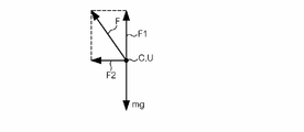
このことを力学的に解説する。図6に示すように、揚力の中心U(接続部の中心C)に作用する力は、支持棒21、第1搭載部25及びカメラ28等の搭載物による重力mgと、回転翼12A、12B、12C、12Dの回転による揚力Fである。重力mgの向きは鉛直方向下方であり、揚力Fの向きは、各回転翼12A、12B、12C、12の幅方向における上端からd/nの位置を通る平面に直交する上方向である。揚力Fを、重力mgの向きに平行な方向の分力F1と、重力mgの向きに垂直な方向の分力F2とに分解すると、分力F1は重力mgと釣り合い、分力F2は回転翼機10の水平方向の推進力となる。この分力F1、F2によって、回転翼機10は高度を維持したまま水平方向に移動する。
Let us explain this mechanically. As shown in FIG. 6, the force acting on the center of lift U (the center of the connecting portion C) is composed of gravity mg caused by mounted objects such as the
以上に説明したように本実施形態によれば、回転翼機10が水平方向に進行する場合に、進行方向前方及び後方の各回転翼の回転数の差を従来よりも小さくすること、例えばその差をゼロにすることができる。
As described above, according to the present embodiment, when the
進行方向前方及び後方の各回転翼の回転数の差を従来よりも小さくすると、次のような利点がある。まず、回転翼機10が水平方向に移動する期間にわたって、進行方向後方の回転翼の出力を進行方向前方の出力よりも相当に高い状態(従来生じていた回転モーメントMを打ち消すだけの高出力)で維持する必要がないため、その動力部がモータであった場合には発熱等による故障の可能性が小さくなるし、また、従来よりも出力性能の低い、ダウングレードされた動力部を利用する余地が生まれる。このように動力部のダウングレードを図ることが許容されるならば、回転翼機の機体全体の軽量化やコストダウンも可能となり、その結果、燃費の向上や経済的なメリットを享受できる。
Reducing the difference in rotational speed between the front and rear rotor blades in the traveling direction has the following advantages. First, during the period in which the
また、従来のように進行方向前方及び後方の各回転翼の回転数に差を設けた場合には、進行方向前方の回転翼の回転数は相対的に少なくなり、且つ、後方の動力部の出力は高くしたとしてもその出力の一部は回転モーメントの解消に充てなければならないので、結果として、全回転翼の平均的な回転数はあまり多くならない。このため、回転翼機の進行速度はあまり速くならないし、また、回転翼機によって搬送可能な重量物の重量もあまり重くはできない。これに対して、本実施形態によれば、動力部13A、13B、13C、13Dの出力を回転モーメントの解消に充てずに済み、その出力を回転翼機の推進力に充てる割合を従来よりも高めることができる。よって、回転翼機の進行速度の向上に寄与するし、また、より重い荷物を搬送することも可能となる。
In addition, when a difference is provided in the rotational speed of the front and rear rotor blades in the direction of travel as in the conventional art, the rotational speed of the front rotor blade in the direction of travel is relatively small, and the rear power section Even if the output is increased, part of the output must be used to eliminate the rotational moment, so the average number of rotations of all the rotor blades does not increase very much as a result. For this reason, the traveling speed of the rotorcraft is not very high, and the weight of heavy objects that can be carried by the rotorcraft cannot be too heavy. In contrast, according to the present embodiment, the output of the
また、回転翼機で荷物を運搬して目的地上方の空中でその荷物を切り離して目的地に落下させるような運搬用途の場合、従来の構成では、荷物を回転翼機から切り離した瞬間に、荷物の重量に相当する分だけ回転モーメントMが一気に小さくなり、さらに、進行方向前方及び後方で回転数レベルに差があるので、回転翼機の機体の挙動が極めて不安定になる。これに対し、本実施形態によれば回転モーメントが生じておらず、また、進行方向前方及び後方で回転数レベルの差もないので、荷物を切り離したとしても回転モーメントが変化する余地はなく、上記のような問題は生じない。 In addition, in the case of a transportation application in which a load is transported by a rotary wing aircraft, separated in the air above the destination, and dropped at the destination, in the conventional configuration, the moment the load is separated from the rotary wing aircraft, The rotation moment M is suddenly reduced by an amount corresponding to the weight of the cargo, and furthermore, there is a difference in the rotational speed level between the front and rear in the direction of travel, so the behavior of the rotorcraft body becomes extremely unstable. On the other hand, according to the present embodiment, no rotational moment is generated, and there is no difference in the rotational speed level between the front and rear in the traveling direction, so there is no room for the rotational moment to change even if the load is separated. Problems such as those described above do not occur.
[変形例]
上記の第1の実施の形態を次のように変形してもよい。
[変形例1]
回転翼機の機体の重心を移動させる重心移動機構を備えるようにしてもよい。図7は、変形例1に係る回転翼機10Aの側面図であり、図8は、回転翼機10Aの姿勢変化を示す側面図である。接続部16Aは、当該接続部16Aから見て第1搭載部25とは反対側に配置された第2搭載部26を、第1搭載部25とともにアーム部14A、14B、14C、14Dに接続する。第2搭載部26は、第1搭載部25に支持棒21及び支持棒22を介して連結されている。第2搭載部26には、電源、受信機、制御装置又は水平器などのほか、測位用の信号(例えばGPS信号)を受信するアンテナなどが搭載されていてもよい。支持棒21及び支持棒22は、一方向に延びる1本の棒状部材であり、アーム部14A、14B、14C、14D及び回転翼部11A、11B、11C、11Dに干渉しない範囲で、ボールジョイント等の接続部16Aを中心として、機体に対して搖動可能になっている。
[Modification]
The first embodiment described above may be modified as follows.
[Modification 1]
A center-of-gravity moving mechanism for moving the center of gravity of the rotorcraft body may be provided. FIG. 7 is a side view of the
さらに、第1搭載部25、第2搭載部26及び支持棒21、22は、接続部16Aに設けられた例えばラックピニオン機構等によって、その接続部16Aに対して上下動が可能になっている。この上下動の機構により第1搭載部25及び第2搭載部26が下方(矢印f方向)に下がると、接続部16Aから見て第1搭載部25側の重量のほうが第2搭載部26側の重量よりも重い状態になる。これにより、回転翼機10Aの機体の重心の位置が下がる。この場合、回転翼機10の姿勢に関わらず、重力の作用によって、回転翼機10の鉛直方向下方に第1搭載部25が位置し且つ回転翼機10の鉛直方向上方に第2搭載部26が位置した状態を維持することができる。一方、この上下動の機構により第1搭載部25及び第2搭載部26が上方(矢印e方向)に上がると、接続部16Aから見て第2搭載部26側の重量のほうが第1搭載部25側の重量よりも重い状態になり、回転翼機10Aの機体の重心の位置が上がることになる。つまり、接続部16A、第1搭載部25、第2搭載部26及び支持棒21、22は回転翼機の機体の重心を移動させる重心移動機構を構成している。
Furthermore, the first mounting
本変形例1によれば、上記実施形態と同様の制御によって、図8に示すように、各回転翼12A、12B、12C、12Dの回転数を同じにしたまま、回転翼機10Aを水平方向に移動させることができる。さらに、第2搭載部26に測位用の信号(例えばGPS信号)を受信するアンテナを搭載した場合、接続部16Aから見て第1搭載部25側の重量を第2搭載部26側の重量よりも重い状態にすると、そのアンテナの向きは常に一定に維持できるので(つまりアンテナは常に鉛直方向上方に向く)、アンテナの指向性や利得を一定に維持することができる。さらに、第1搭載部25、第2搭載部26及び支持棒21、22を接続部16Aに対して上下動させることで回転翼機10Aの重心の位置を変えることができるが、このような重心変更は、いずれかの回転翼部11A、11B、11C、11Dが故障した場合に回転翼機10の姿勢を維持するうえで有効である。具体的には、故障して停止した回転翼部に回転翼機10Aの機体の重心を近づけるようにして、機体の重心移動および機体の姿勢変化を行うようにすると、残った回転翼部だけで飛行を継続することが可能となる。
According to
[変形例2]
上述した実施形態や変形例1では、第1搭載部25又は第2搭載部26が接続部16、16Aを中心として重力の作用で自由に回転移動できるようになっていたが、これらの移動をモータや補助プロペラのような動力部を用い、操縦者の操作に応じて能動的に制御してもよい。例えば上記実施形態の場合、支持棒21が接続部16を起点としてアーム部14A、14B、14C、14Dに対して可変になるような駆動機構と、その駆動機構を駆動するモータとを回転翼機10に設ける。操縦者は送信機を操作して、回転翼機10が所望の高度に到着すると、進行方向後方にある回転翼12B、12Cの回転数を進行方向前方にある回転翼12A、12Dの回転数よりも多くすることで回転翼機10の姿勢を進行方向前下がりに傾かせ、さらにその傾きに合わせて、上記駆動機構を利用して第1搭載部25が接続部16の鉛直方向下方に位置するように制御する。この制御は操縦者の手動で行ってもよいし、回転翼機10の制御装置が所定の制御アルゴリズムに基づき回転翼機10の傾きに応じて自動的に行ってもよい。また、第1搭載部25に、上方から見たとき互いに直交する2方向に推進力を発生させる補助プロペラを2つ設け、その補助プロペラによる推進力で第1搭載部25の位置を制御してもよい。
以上のように、接続部は、第1搭載部が重力によって移動可能となるようにアーム部に接続してもよいし、第1搭載部が動力部によって移動可能となるようにアーム部に接続してもよい。
[Modification 2]
In the above-described embodiment and
As described above, the connection section may be connected to the arm section so that the first mounting section can be moved by gravity, or connected to the arm section so that the first mounting section can be moved by the power section. You may
[変形例3]
変形例1において、接続部16Aから見て第1搭載部25側の重量と第2搭載部26側の重量とを同じにしておけば、図9に示すように、回転翼機10Aが水平方向に移動する際に、支持棒21及び支持棒22の姿勢を水平に保つことができる。この場合において、例えば第2搭載部26にカメラ28を搭載しておくと、カメラ28の撮像方向は回転翼機10の進行方向になるので、例えば回転翼12Aなどがカメラ28の撮像範囲に入って邪魔になる可能性を低減することができる。また、支持棒21及び支持棒22の姿勢が垂直の場合に比べ、支持棒21及び支持棒22の姿勢を水平の場合には、水平方向に進行するときの機体の空気抵抗を小さくすることが可能となる。
[Modification 3]
In Modified Example 1, if the weight on the first mounting
[変形例4]
回転翼機の構造は、実施形態に例示したものに限らず、例えば図10~12に示すような構造であってもよい。変形例4に係る回転翼機10Bは、回転翼部11A、11B、11C、11Dを支持するアーム部141が上方から見たときに矩形の形状となるように構成されている。接続部16Bは、水平なx軸周りに回転可能となるようにアーム部141に回転軸1621で接続された枠体161と、x軸に直交する水平なy軸周りに回転可能となるように枠体161にピン1611で接続された枠体162とを備えている。アーム部141と枠体161との間には、枠体161のx軸周りの回転運動を抑制するダンパ171が設けられており、枠体161と枠体162との間には、枠体162のy軸周りの回転運動を抑制するダンパ172が設けられている。このダンパ171、172は、枠体161、162が回転運動して第1搭載部25が急激に変位することで回転翼機10Bの姿勢が不安定にならないように、その変位に要する時間を長くするための手段である。
[Modification 4]
The structure of the rotorcraft is not limited to those illustrated in the embodiments, and may be structures as shown in FIGS. 10 to 12, for example. A
[変形例5]
本発明は、回転翼機が水平方向に進行する場合に限らず、水平方向を含む方向(つまり水平方向のベクトル成分を持つ方向)に進行する場合にも適用可能である。つまり、図6で説明した重力mgの向きに平行な方向の分力F1が、重力mgよりも大きい又は小さい場合であっても、進行方向前方及び後方の各回転翼の回転数の差を従来よりも小さくすることができる。
[Modification 5]
The present invention is applicable not only when the rotorcraft travels in the horizontal direction, but also when it travels in directions including the horizontal direction (that is, directions with vector components in the horizontal direction). That is, even if the component force F1 in the direction parallel to the direction of the gravity mg explained in FIG. can be smaller than
[変形例6]
電源は回転翼機に搭載する必要はなく、例えば地上に電源を設置し、その電源から延びる電源ケーブルを回転翼機に接続して電力供給を行ってもよい。また、高度15m程度の高度であれば、非接触電力伝送の受信機を中心部、第1搭載部又は第2搭載部に設置し、地上から回転翼機に無線で給電してもよい。
[Modification 6]
The power supply need not be mounted on the rotorcraft. For example, a power supply may be installed on the ground and a power cable extending from the power supply may be connected to the rotorcraft to supply power. At an altitude of about 15 m, a receiver for contactless power transmission may be installed in the central part, the first mounting part, or the second mounting part, and power may be supplied wirelessly from the ground to the rotorcraft.
(第2の実施の形態)
上本発明の第2の実施の形態について、図16乃至図18を参照して説明する。なお、以下における説明では、同一又は類似の要素については同一の参照符号を付しその詳細な説明を省略する。
(Second embodiment)
A second embodiment of the present invention will be described with reference to FIGS. 16 to 18. FIG. In the description below, the same or similar elements are denoted by the same reference numerals, and detailed description thereof will be omitted.
図16に示されるように、第2の実施の形態による回転翼機もまた、飛行部と、本体部と、飛行部及び本体部を所定の範囲で搖動可能に接続する接続部とを備えている。回転翼機は、主として進行方向(X方向)に飛行する。 As shown in FIG. 16, the rotorcraft according to the second embodiment also includes a flying section, a main body, and a connecting section that connects the flying section and the main body so that they can swing within a predetermined range. there is A rotorcraft flies primarily in the direction of travel (the X direction).
飛行部は、回転翼11A、11B(11C、11Dは図示せず)と、これらに動力を供給する動力部(モータ)13A、13B(13C、13Dは図示せず)と、動力部13A、13Bを支持するアーム部14A、14B(14C、14Dは図示せず)とを備えている。
The flight section includes
本体部は、上下方向に延びる支持棒と、当該支持棒の上端及び下端に夫々設けられた第1搭載部及び第2搭載部とを備えている。支持棒は下方に延びる下側の支持棒21と上側に延びる上側の支持棒22とを有している。第1搭載部にはカメラ28Tが搭載されており、第2搭載部にはカメラ28Bが搭載されている。
The main body includes a vertically extending support rod, and a first mounting portion and a second mounting portion provided at upper and lower ends of the support rod, respectively. The support bars have a
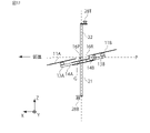
本実施の形態による接続部は、第1接続部16Pと、第2接続部16Rとを有する所謂2軸ジンバル構造を有している。第1接続部16Pは、ピッチ方向(水平軸周りに)に本体部を搖動可能に接続する。第2接続部16Rは、進行方向(X軸)と仰角θをなす斜交軸P周りに本体部を搖動可能にする。
The connecting portion according to the present embodiment has a so-called biaxial gimbal structure having a first connecting
本実施の形態による水平軸と斜交軸との交点は、回転翼11A、11B(11C、11Dは図示せず)回転翼11A、11B(11C、11Dは図示せず)によつて生じる揚力の中心と略一致する。より詳しくは、交点の位置は、が回転することによって機体に発生する揚力の当該回転翼機に対する作用点であって各回転翼の短手方向の幅内の位置を通る平面上であって、且つ各複数の回転翼の回転軸が通る円の中心の位置にある作用点と略一致する位置にある。更に、本実施の形態による上記の交点は、本体部の重心Gと略一致する。
The points of intersection between the horizontal axis and the oblique axis according to this embodiment are the lift forces generated by the
また、図示されるように、カメラ28Tの位置は、本体部から後方にずれており、カメラ28Bの位置は、本体部から前方にずれている。これにより、前後方向において互いにカウンタウェイトとして機能するとともに、進行方向への飛行時に回転翼が視野内に入りにくくなる。
Also, as shown in the figure, the position of the
図17に示されるように、回転翼機は、飛行部を進行方向に傾けるようにして進行方向に移動させる。この時、斜交軸Pは水平方向と平行になるときがある。即ち、図16に示される仰角θは、少なくとも進行方向への飛行時に斜交軸Pが水平となり得る角度であり、換言すれば、進行方向への飛行時に斜交軸が少なくとも水平方向をとれる瞬間があるように設定される。詳しくは、仰角θは、10度から35度が望ましく、進行方向への飛行速度を重視する場合には25度乃至35度が望ましく、飛行速度が低速の場合には10度乃至15度が望ましい。 As shown in FIG. 17, the rotorcraft moves in the direction of travel by tilting the flight section in the direction of travel. At this time, the oblique axis P is sometimes parallel to the horizontal direction. That is, the elevation angle θ shown in FIG. 16 is an angle at which the oblique axis P can be horizontal at least during flight in the forward direction, in other words, the moment when the oblique axis can be at least horizontal during flight in the forward direction. is set to be Specifically, the elevation angle θ is preferably 10 to 35 degrees, preferably 25 to 35 degrees when the flight speed in the direction of travel is important, and 10 to 15 degrees when the flight speed is low. .
図18に示されるように、より進行方向の飛行速度を増加させた場合、斜交軸は水平方向と俯角をなすこととなる。 As shown in FIG. 18, when the flight speed in the direction of travel is further increased, the oblique axis forms an angle of depression with the horizontal direction.
このように、初期状態(垂直上昇時)において、予め斜交軸を進行方向と仰角をなすようにしておくことにより、飛行時において、適切な姿勢を維持しやすくなるとともに、特に、第2接続部16Rの有効角が増加するため、佐生光速度の引き上げが可能となる。また、接続部にモータを使用する場合には当該モータの出力を小さなもので構成することができる。
In this way, in the initial state (at the time of vertical ascent), by making the oblique axis form an elevation angle in advance with the traveling direction, it becomes easier to maintain an appropriate attitude during flight, and in particular, the second connection. Since the effective angle of the
<変形例>
上述した第2の実施の形態は、例えば、図19のような変形例として構成してもよい。図示されるように本変形例における回転翼機は、カメラ28Tが本体部の軸上にある(即ち、後方にずれていない)。カメラ28Bは前方に位置している方が回転翼の映り込み等を抑えることができ、かつ、上下のカメラ28T、28Bで取得した画像を合成する場合にはできるだけ互いの位置が同軸に近い方が好ましいためである。
<Modification>
The above-described second embodiment may be configured as a modified example as shown in FIG. 19, for example. As shown, the rotorcraft in this modification has the
10、10A、10B、10C…回転翼機、11A、11B、11C、11D…回転翼部、12A、12B、12C、12D…回転翼、13A、13B、13C、13D…動力部、14A、14B、14C、14D、141…アーム部、15…中心部、16、16A、16B…接続部、161、162…枠体、21、22…支持棒、25…第1搭載部、26…第2搭載部、28…カメラ
10, 10A, 10B, 10C... rotary wing aircraft, 11A, 11B, 11C, 11D... rotary wing section, 12A, 12B, 12C, 12D... rotary wing, 13A, 13B, 13C, 13D... power section, 14A, 14B, 14C, 14D, 141
Claims (5)
前記飛行部は、複数の回転翼と、前記複数の回転翼を支持するアーム部とを備えており、
前記本体部は、上下方向に延びる部材と、当該部材の上端側及び下端側に夫々設けられた第1搭載部及び第2搭載部とを備えており、
前記接続部は、進行方向と直交する水平軸周りに前記本体部を搖動可能にする第1接続部と、前記水平軸と直交し且つ垂直上昇時に水平よりも上向きに所定の仰角をなす斜交軸周りに前記本体部を搖動可能にする第2接続部とを有している、
回転翼機。 A rotary wing aircraft comprising a flight section, a body section, and a connecting section connecting the flight section and the body section so as to be able to swing within a predetermined range,
The flight section includes a plurality of rotor blades and an arm portion supporting the plurality of rotor blades,
The main body includes a member extending in the vertical direction, and a first mounting portion and a second mounting portion provided on the upper end side and the lower end side of the member , respectively,
The connecting portion includes a first connecting portion that allows the main body to swing about a horizontal axis perpendicular to the traveling direction, and an oblique connecting portion that is perpendicular to the horizontal axis and forms a predetermined elevation angle above the horizontal when vertically rising. a second connecting portion that allows the body portion to swing about an axis;
rotorcraft.
前記水平軸と前記斜交軸との交点は、前記複数の回転翼が回転することによって機体に発生する揚力の略中心位置にあることを特徴とする
回転翼機。 A rotorcraft according to claim 1,
A rotary wing aircraft, wherein the intersection of the horizontal axis and the oblique axis is substantially at the center position of the lift generated in the fuselage by the rotation of the plurality of rotary wings.
前記水平軸と前記斜交軸との交点は、前記本体部の重心にあることを特徴とする
回転翼機。 A rotorcraft according to claim 1,
A rotary wing aircraft, wherein the intersection of the horizontal axis and the oblique axis is at the center of gravity of the main body.
前記第1搭載部の位置は、前記本体部から後方にずれており、
前記第2搭載部の位置は、前記本体部から前方にずれている、
回転翼機。 The rotary wing aircraft according to any one of claims 1 to 3,
The position of the first mounting portion is shifted rearward from the main body,
The position of the second mounting portion is shifted forward from the body portion,
rotorcraft.
前記飛行部を進行方向に傾けるようにして進行方向に移動し
前記仰角は、少なくとも進行方向への飛行時に前記斜交軸が水平となり得る角度である、
回転翼機。
The rotorcraft according to any one of claims 1 to 4,
The flight unit moves in the direction of travel so as to be tilted in the direction of travel, and the elevation angle is an angle at which the oblique axis can be horizontal at least during flight in the direction of travel.
rotorcraft.
Priority Applications (2)
| Application Number | Priority Date | Filing Date | Title |
|---|---|---|---|
| JP2019187099A JP7120645B2 (en) | 2019-10-10 | 2019-10-10 | rotorcraft |
| JP2022120658A JP7240050B2 (en) | 2019-10-10 | 2022-07-28 | rotorcraft |
Applications Claiming Priority (1)
| Application Number | Priority Date | Filing Date | Title |
|---|---|---|---|
| JP2019187099A JP7120645B2 (en) | 2019-10-10 | 2019-10-10 | rotorcraft |
Related Parent Applications (1)
| Application Number | Title | Priority Date | Filing Date |
|---|---|---|---|
| JP2019541468A Division JP6607480B1 (en) | 2018-08-13 | 2018-08-13 | Rotorcraft |
Related Child Applications (1)
| Application Number | Title | Priority Date | Filing Date |
|---|---|---|---|
| JP2022120658A Division JP7240050B2 (en) | 2019-10-10 | 2022-07-28 | rotorcraft |
Publications (3)
| Publication Number | Publication Date |
|---|---|
| JP2020026270A JP2020026270A (en) | 2020-02-20 |
| JP2020026270A5 JP2020026270A5 (en) | 2021-09-30 |
| JP7120645B2 true JP7120645B2 (en) | 2022-08-17 |
Family
ID=69621847
Family Applications (1)
| Application Number | Title | Priority Date | Filing Date |
|---|---|---|---|
| JP2019187099A Active JP7120645B2 (en) | 2019-10-10 | 2019-10-10 | rotorcraft |
Country Status (1)
| Country | Link |
|---|---|
| JP (1) | JP7120645B2 (en) |
Families Citing this family (3)
| Publication number | Priority date | Publication date | Assignee | Title |
|---|---|---|---|---|
| CN113581455B (en) * | 2021-08-05 | 2023-08-01 | 广东智联航空科技有限公司 | Multi-rotor aircraft with constant center of gravity |
| AU2022343911A1 (en) * | 2021-09-13 | 2024-03-28 | Orthodrone Gmbh | Aircraft |
| KR20230120915A (en) * | 2022-02-10 | 2023-08-17 | 디스이즈엔지니어링 주식회사 | Air vehicle |
Citations (4)
| Publication number | Priority date | Publication date | Assignee | Title |
|---|---|---|---|---|
| WO2016185572A1 (en) | 2015-05-19 | 2016-11-24 | 株式会社0 | Rotorcraft |
| JP2016219941A (en) | 2015-05-18 | 2016-12-22 | 株式会社amuse oneself | Unmanned aerial vehicle |
| JP6086519B1 (en) | 2016-10-03 | 2017-03-01 | 株式会社0 | Delivery rotorcraft |
| JP2017193208A (en) | 2016-04-18 | 2017-10-26 | 株式会社自律制御システム研究所 | Small-sized unmanned aircraft |
-
2019
- 2019-10-10 JP JP2019187099A patent/JP7120645B2/en active Active
Patent Citations (4)
| Publication number | Priority date | Publication date | Assignee | Title |
|---|---|---|---|---|
| JP2016219941A (en) | 2015-05-18 | 2016-12-22 | 株式会社amuse oneself | Unmanned aerial vehicle |
| WO2016185572A1 (en) | 2015-05-19 | 2016-11-24 | 株式会社0 | Rotorcraft |
| JP2017193208A (en) | 2016-04-18 | 2017-10-26 | 株式会社自律制御システム研究所 | Small-sized unmanned aircraft |
| JP6086519B1 (en) | 2016-10-03 | 2017-03-01 | 株式会社0 | Delivery rotorcraft |
Also Published As
| Publication number | Publication date |
|---|---|
| JP2020026270A (en) | 2020-02-20 |
Similar Documents
| Publication | Publication Date | Title |
|---|---|---|
| CN107614376B (en) | Rotorcraft | |
| JP7120645B2 (en) | rotorcraft | |
| US20060113425A1 (en) | Vertical take-off and landing aircraft with adjustable center-of-gravity position | |
| JP6550563B2 (en) | Rotorcraft | |
| KR101664899B1 (en) | multicopter | |
| JP6607480B1 (en) | Rotorcraft | |
| JP6550562B2 (en) | Rotorcraft | |
| EP3795470A1 (en) | Aircraft and method for controlling aircraft | |
| JP6618000B1 (en) | Electronic component and flying object with the electronic component attached | |
| JP6550561B2 (en) | Rotorcraft | |
| JP7240050B2 (en) | rotorcraft | |
| JP2019089548A (en) | Rotary wing aircraft | |
| WO2022049764A1 (en) | Flying vehicle | |
| JP6473256B2 (en) | Rotorcraft | |
| JP6970479B1 (en) | Flying object | |
| JP3236741U (en) | Tail sitter type flying object | |
| CN112292317B (en) | Flying body and method for controlling flying body | |
| WO2021157343A1 (en) | Vertical takeoff and landing aircraft |
Legal Events
| Date | Code | Title | Description |
|---|---|---|---|
| A621 | Written request for application examination |
Free format text: JAPANESE INTERMEDIATE CODE: A621 Effective date: 20210812 |
|
| A521 | Request for written amendment filed |
Free format text: JAPANESE INTERMEDIATE CODE: A523 Effective date: 20210817 |
|
| TRDD | Decision of grant or rejection written | ||
| A01 | Written decision to grant a patent or to grant a registration (utility model) |
Free format text: JAPANESE INTERMEDIATE CODE: A01 Effective date: 20220707 |
|
| A61 | First payment of annual fees (during grant procedure) |
Free format text: JAPANESE INTERMEDIATE CODE: A61 Effective date: 20220728 |
|
| R150 | Certificate of patent or registration of utility model |
Ref document number: 7120645 Country of ref document: JP Free format text: JAPANESE INTERMEDIATE CODE: R150 |