JP6633788B1 - Power supply unit for aerosol inhaler - Google Patents
Power supply unit for aerosol inhaler Download PDFInfo
- Publication number
- JP6633788B1 JP6633788B1 JP2019035981A JP2019035981A JP6633788B1 JP 6633788 B1 JP6633788 B1 JP 6633788B1 JP 2019035981 A JP2019035981 A JP 2019035981A JP 2019035981 A JP2019035981 A JP 2019035981A JP 6633788 B1 JP6633788 B1 JP 6633788B1
- Authority
- JP
- Japan
- Prior art keywords
- power supply
- voltage
- zener diode
- supply unit
- control device
- Prior art date
- Legal status (The legal status is an assumption and is not a legal conclusion. Google has not performed a legal analysis and makes no representation as to the accuracy of the status listed.)
- Active
Links
- 239000000443 aerosol Substances 0.000 title claims abstract description 127
- 238000007599 discharging Methods 0.000 claims abstract description 16
- 239000003990 capacitor Substances 0.000 claims description 92
- 238000010586 diagram Methods 0.000 abstract description 9
- 239000000796 flavoring agent Substances 0.000 description 19
- 235000019634 flavors Nutrition 0.000 description 19
- 230000015556 catabolic process Effects 0.000 description 10
- 230000020169 heat generation Effects 0.000 description 8
- 238000001514 detection method Methods 0.000 description 6
- 238000010438 heat treatment Methods 0.000 description 6
- 230000010349 pulsation Effects 0.000 description 6
- 238000009499 grossing Methods 0.000 description 4
- 241000208125 Nicotiana Species 0.000 description 3
- 235000002637 Nicotiana tabacum Nutrition 0.000 description 3
- DNIAPMSPPWPWGF-UHFFFAOYSA-N Propylene glycol Chemical compound CC(O)CO DNIAPMSPPWPWGF-UHFFFAOYSA-N 0.000 description 3
- 230000006870 function Effects 0.000 description 3
- 238000011144 upstream manufacturing Methods 0.000 description 3
- PEDCQBHIVMGVHV-UHFFFAOYSA-N Glycerine Chemical compound OCC(O)CO PEDCQBHIVMGVHV-UHFFFAOYSA-N 0.000 description 2
- 238000000889 atomisation Methods 0.000 description 2
- 230000005540 biological transmission Effects 0.000 description 2
- 239000000919 ceramic Substances 0.000 description 2
- 239000003814 drug Substances 0.000 description 2
- 239000007788 liquid Substances 0.000 description 2
- 239000002994 raw material Substances 0.000 description 2
- 230000006641 stabilisation Effects 0.000 description 2
- 238000011105 stabilization Methods 0.000 description 2
- 230000003068 static effect Effects 0.000 description 2
- 239000000758 substrate Substances 0.000 description 2
- NOOLISFMXDJSKH-UTLUCORTSA-N (+)-Neomenthol Chemical compound CC(C)[C@@H]1CC[C@@H](C)C[C@@H]1O NOOLISFMXDJSKH-UTLUCORTSA-N 0.000 description 1
- 229920000742 Cotton Polymers 0.000 description 1
- NOOLISFMXDJSKH-UHFFFAOYSA-N DL-menthol Natural products CC(C)C1CCC(C)CC1O NOOLISFMXDJSKH-UHFFFAOYSA-N 0.000 description 1
- 241000196324 Embryophyta Species 0.000 description 1
- HBBGRARXTFLTSG-UHFFFAOYSA-N Lithium ion Chemical compound [Li+] HBBGRARXTFLTSG-UHFFFAOYSA-N 0.000 description 1
- 235000006679 Mentha X verticillata Nutrition 0.000 description 1
- 235000002899 Mentha suaveolens Nutrition 0.000 description 1
- 235000001636 Mentha x rotundifolia Nutrition 0.000 description 1
- 229940079593 drug Drugs 0.000 description 1
- 230000005611 electricity Effects 0.000 description 1
- 230000005674 electromagnetic induction Effects 0.000 description 1
- 230000008030 elimination Effects 0.000 description 1
- 238000003379 elimination reaction Methods 0.000 description 1
- 239000003365 glass fiber Substances 0.000 description 1
- 235000011187 glycerol Nutrition 0.000 description 1
- 239000008187 granular material Substances 0.000 description 1
- 230000006698 induction Effects 0.000 description 1
- 229910001416 lithium ion Inorganic materials 0.000 description 1
- 229940041616 menthol Drugs 0.000 description 1
- 238000000034 method Methods 0.000 description 1
- 230000002093 peripheral effect Effects 0.000 description 1
- 230000002265 prevention Effects 0.000 description 1
- 239000011347 resin Substances 0.000 description 1
- 229920005989 resin Polymers 0.000 description 1
- 239000004065 semiconductor Substances 0.000 description 1
- 230000000087 stabilizing effect Effects 0.000 description 1
- 239000000126 substance Substances 0.000 description 1
- XLYOFNOQVPJJNP-UHFFFAOYSA-N water Substances O XLYOFNOQVPJJNP-UHFFFAOYSA-N 0.000 description 1
Images


Classifications
-
- H—ELECTRICITY
- H02—GENERATION; CONVERSION OR DISTRIBUTION OF ELECTRIC POWER
- H02J—CIRCUIT ARRANGEMENTS OR SYSTEMS FOR SUPPLYING OR DISTRIBUTING ELECTRIC POWER; SYSTEMS FOR STORING ELECTRIC ENERGY
- H02J7/00—Circuit arrangements for charging or depolarising batteries or for supplying loads from batteries
- H02J7/0068—Battery or charger load switching, e.g. concurrent charging and load supply
-
- H—ELECTRICITY
- H02—GENERATION; CONVERSION OR DISTRIBUTION OF ELECTRIC POWER
- H02J—CIRCUIT ARRANGEMENTS OR SYSTEMS FOR SUPPLYING OR DISTRIBUTING ELECTRIC POWER; SYSTEMS FOR STORING ELECTRIC ENERGY
- H02J7/00—Circuit arrangements for charging or depolarising batteries or for supplying loads from batteries
-
- A—HUMAN NECESSITIES
- A24—TOBACCO; CIGARS; CIGARETTES; SIMULATED SMOKING DEVICES; SMOKERS' REQUISITES
- A24F—SMOKERS' REQUISITES; MATCH BOXES; SIMULATED SMOKING DEVICES
- A24F40/00—Electrically operated smoking devices; Component parts thereof; Manufacture thereof; Maintenance or testing thereof; Charging means specially adapted therefor
- A24F40/30—Devices using two or more structurally separated inhalable precursors, e.g. using two liquid precursors in two cartridges
-
- A—HUMAN NECESSITIES
- A24—TOBACCO; CIGARS; CIGARETTES; SIMULATED SMOKING DEVICES; SMOKERS' REQUISITES
- A24F—SMOKERS' REQUISITES; MATCH BOXES; SIMULATED SMOKING DEVICES
- A24F40/00—Electrically operated smoking devices; Component parts thereof; Manufacture thereof; Maintenance or testing thereof; Charging means specially adapted therefor
- A24F40/40—Constructional details, e.g. connection of cartridges and battery parts
- A24F40/42—Cartridges or containers for inhalable precursors
-
- A—HUMAN NECESSITIES
- A24—TOBACCO; CIGARS; CIGARETTES; SIMULATED SMOKING DEVICES; SMOKERS' REQUISITES
- A24F—SMOKERS' REQUISITES; MATCH BOXES; SIMULATED SMOKING DEVICES
- A24F40/00—Electrically operated smoking devices; Component parts thereof; Manufacture thereof; Maintenance or testing thereof; Charging means specially adapted therefor
- A24F40/50—Control or monitoring
- A24F40/51—Arrangement of sensors
-
- A—HUMAN NECESSITIES
- A24—TOBACCO; CIGARS; CIGARETTES; SIMULATED SMOKING DEVICES; SMOKERS' REQUISITES
- A24F—SMOKERS' REQUISITES; MATCH BOXES; SIMULATED SMOKING DEVICES
- A24F40/00—Electrically operated smoking devices; Component parts thereof; Manufacture thereof; Maintenance or testing thereof; Charging means specially adapted therefor
- A24F40/50—Control or monitoring
- A24F40/53—Monitoring, e.g. fault detection
-
- A—HUMAN NECESSITIES
- A24—TOBACCO; CIGARS; CIGARETTES; SIMULATED SMOKING DEVICES; SMOKERS' REQUISITES
- A24F—SMOKERS' REQUISITES; MATCH BOXES; SIMULATED SMOKING DEVICES
- A24F40/00—Electrically operated smoking devices; Component parts thereof; Manufacture thereof; Maintenance or testing thereof; Charging means specially adapted therefor
- A24F40/50—Control or monitoring
- A24F40/57—Temperature control
-
- A—HUMAN NECESSITIES
- A24—TOBACCO; CIGARS; CIGARETTES; SIMULATED SMOKING DEVICES; SMOKERS' REQUISITES
- A24F—SMOKERS' REQUISITES; MATCH BOXES; SIMULATED SMOKING DEVICES
- A24F40/00—Electrically operated smoking devices; Component parts thereof; Manufacture thereof; Maintenance or testing thereof; Charging means specially adapted therefor
- A24F40/60—Devices with integrated user interfaces
-
- A—HUMAN NECESSITIES
- A24—TOBACCO; CIGARS; CIGARETTES; SIMULATED SMOKING DEVICES; SMOKERS' REQUISITES
- A24F—SMOKERS' REQUISITES; MATCH BOXES; SIMULATED SMOKING DEVICES
- A24F40/00—Electrically operated smoking devices; Component parts thereof; Manufacture thereof; Maintenance or testing thereof; Charging means specially adapted therefor
- A24F40/90—Arrangements or methods specially adapted for charging batteries thereof
- A24F40/95—Arrangements or methods specially adapted for charging batteries thereof structurally associated with cases
-
- A—HUMAN NECESSITIES
- A61—MEDICAL OR VETERINARY SCIENCE; HYGIENE
- A61M—DEVICES FOR INTRODUCING MEDIA INTO, OR ONTO, THE BODY; DEVICES FOR TRANSDUCING BODY MEDIA OR FOR TAKING MEDIA FROM THE BODY; DEVICES FOR PRODUCING OR ENDING SLEEP OR STUPOR
- A61M11/00—Sprayers or atomisers specially adapted for therapeutic purposes
- A61M11/04—Sprayers or atomisers specially adapted for therapeutic purposes operated by the vapour pressure of the liquid to be sprayed or atomised
- A61M11/041—Sprayers or atomisers specially adapted for therapeutic purposes operated by the vapour pressure of the liquid to be sprayed or atomised using heaters
- A61M11/042—Sprayers or atomisers specially adapted for therapeutic purposes operated by the vapour pressure of the liquid to be sprayed or atomised using heaters electrical
-
- A—HUMAN NECESSITIES
- A61—MEDICAL OR VETERINARY SCIENCE; HYGIENE
- A61M—DEVICES FOR INTRODUCING MEDIA INTO, OR ONTO, THE BODY; DEVICES FOR TRANSDUCING BODY MEDIA OR FOR TAKING MEDIA FROM THE BODY; DEVICES FOR PRODUCING OR ENDING SLEEP OR STUPOR
- A61M15/00—Inhalators
- A61M15/009—Inhalators using medicine packages with incorporated spraying means, e.g. aerosol cans
-
- G—PHYSICS
- G05—CONTROLLING; REGULATING
- G05F—SYSTEMS FOR REGULATING ELECTRIC OR MAGNETIC VARIABLES
- G05F3/00—Non-retroactive systems for regulating electric variables by using an uncontrolled element, or an uncontrolled combination of elements, such element or such combination having self-regulating properties
- G05F3/02—Regulating voltage or current
- G05F3/08—Regulating voltage or current wherein the variable is dc
- G05F3/10—Regulating voltage or current wherein the variable is dc using uncontrolled devices with non-linear characteristics
- G05F3/16—Regulating voltage or current wherein the variable is dc using uncontrolled devices with non-linear characteristics being semiconductor devices
- G05F3/18—Regulating voltage or current wherein the variable is dc using uncontrolled devices with non-linear characteristics being semiconductor devices using Zener diodes
-
- H—ELECTRICITY
- H01—ELECTRIC ELEMENTS
- H01M—PROCESSES OR MEANS, e.g. BATTERIES, FOR THE DIRECT CONVERSION OF CHEMICAL ENERGY INTO ELECTRICAL ENERGY
- H01M10/00—Secondary cells; Manufacture thereof
- H01M10/42—Methods or arrangements for servicing or maintenance of secondary cells or secondary half-cells
- H01M10/425—Structural combination with electronic components, e.g. electronic circuits integrated to the outside of the casing
- H01M10/4264—Structural combination with electronic components, e.g. electronic circuits integrated to the outside of the casing with capacitors
-
- H—ELECTRICITY
- H01—ELECTRIC ELEMENTS
- H01M—PROCESSES OR MEANS, e.g. BATTERIES, FOR THE DIRECT CONVERSION OF CHEMICAL ENERGY INTO ELECTRICAL ENERGY
- H01M10/00—Secondary cells; Manufacture thereof
- H01M10/42—Methods or arrangements for servicing or maintenance of secondary cells or secondary half-cells
- H01M10/44—Methods for charging or discharging
-
- H—ELECTRICITY
- H01—ELECTRIC ELEMENTS
- H01M—PROCESSES OR MEANS, e.g. BATTERIES, FOR THE DIRECT CONVERSION OF CHEMICAL ENERGY INTO ELECTRICAL ENERGY
- H01M10/00—Secondary cells; Manufacture thereof
- H01M10/42—Methods or arrangements for servicing or maintenance of secondary cells or secondary half-cells
- H01M10/48—Accumulators combined with arrangements for measuring, testing or indicating the condition of cells, e.g. the level or density of the electrolyte
-
- H—ELECTRICITY
- H02—GENERATION; CONVERSION OR DISTRIBUTION OF ELECTRIC POWER
- H02J—CIRCUIT ARRANGEMENTS OR SYSTEMS FOR SUPPLYING OR DISTRIBUTING ELECTRIC POWER; SYSTEMS FOR STORING ELECTRIC ENERGY
- H02J7/00—Circuit arrangements for charging or depolarising batteries or for supplying loads from batteries
- H02J7/0029—Circuit arrangements for charging or depolarising batteries or for supplying loads from batteries with safety or protection devices or circuits
- H02J7/0036—Circuit arrangements for charging or depolarising batteries or for supplying loads from batteries with safety or protection devices or circuits using connection detecting circuits
-
- H—ELECTRICITY
- H02—GENERATION; CONVERSION OR DISTRIBUTION OF ELECTRIC POWER
- H02J—CIRCUIT ARRANGEMENTS OR SYSTEMS FOR SUPPLYING OR DISTRIBUTING ELECTRIC POWER; SYSTEMS FOR STORING ELECTRIC ENERGY
- H02J7/00—Circuit arrangements for charging or depolarising batteries or for supplying loads from batteries
- H02J7/0042—Circuit arrangements for charging or depolarising batteries or for supplying loads from batteries characterised by the mechanical construction
- H02J7/0044—Circuit arrangements for charging or depolarising batteries or for supplying loads from batteries characterised by the mechanical construction specially adapted for holding portable devices containing batteries
-
- H—ELECTRICITY
- H02—GENERATION; CONVERSION OR DISTRIBUTION OF ELECTRIC POWER
- H02J—CIRCUIT ARRANGEMENTS OR SYSTEMS FOR SUPPLYING OR DISTRIBUTING ELECTRIC POWER; SYSTEMS FOR STORING ELECTRIC ENERGY
- H02J7/00—Circuit arrangements for charging or depolarising batteries or for supplying loads from batteries
- H02J7/0042—Circuit arrangements for charging or depolarising batteries or for supplying loads from batteries characterised by the mechanical construction
- H02J7/0045—Circuit arrangements for charging or depolarising batteries or for supplying loads from batteries characterised by the mechanical construction concerning the insertion or the connection of the batteries
-
- H—ELECTRICITY
- H02—GENERATION; CONVERSION OR DISTRIBUTION OF ELECTRIC POWER
- H02J—CIRCUIT ARRANGEMENTS OR SYSTEMS FOR SUPPLYING OR DISTRIBUTING ELECTRIC POWER; SYSTEMS FOR STORING ELECTRIC ENERGY
- H02J7/00—Circuit arrangements for charging or depolarising batteries or for supplying loads from batteries
- H02J7/0047—Circuit arrangements for charging or depolarising batteries or for supplying loads from batteries with monitoring or indicating devices or circuits
- H02J7/005—Detection of state of health [SOH]
-
- H—ELECTRICITY
- H02—GENERATION; CONVERSION OR DISTRIBUTION OF ELECTRIC POWER
- H02J—CIRCUIT ARRANGEMENTS OR SYSTEMS FOR SUPPLYING OR DISTRIBUTING ELECTRIC POWER; SYSTEMS FOR STORING ELECTRIC ENERGY
- H02J7/00—Circuit arrangements for charging or depolarising batteries or for supplying loads from batteries
- H02J7/0063—Circuit arrangements for charging or depolarising batteries or for supplying loads from batteries with circuits adapted for supplying loads from the battery
-
- H—ELECTRICITY
- H02—GENERATION; CONVERSION OR DISTRIBUTION OF ELECTRIC POWER
- H02J—CIRCUIT ARRANGEMENTS OR SYSTEMS FOR SUPPLYING OR DISTRIBUTING ELECTRIC POWER; SYSTEMS FOR STORING ELECTRIC ENERGY
- H02J7/00—Circuit arrangements for charging or depolarising batteries or for supplying loads from batteries
- H02J7/007—Regulation of charging or discharging current or voltage
- H02J7/007188—Regulation of charging or discharging current or voltage the charge cycle being controlled or terminated in response to non-electric parameters
- H02J7/007192—Regulation of charging or discharging current or voltage the charge cycle being controlled or terminated in response to non-electric parameters in response to temperature
- H02J7/007194—Regulation of charging or discharging current or voltage the charge cycle being controlled or terminated in response to non-electric parameters in response to temperature of the battery
-
- H—ELECTRICITY
- H02—GENERATION; CONVERSION OR DISTRIBUTION OF ELECTRIC POWER
- H02J—CIRCUIT ARRANGEMENTS OR SYSTEMS FOR SUPPLYING OR DISTRIBUTING ELECTRIC POWER; SYSTEMS FOR STORING ELECTRIC ENERGY
- H02J7/00—Circuit arrangements for charging or depolarising batteries or for supplying loads from batteries
- H02J7/02—Circuit arrangements for charging or depolarising batteries or for supplying loads from batteries for charging batteries from ac mains by converters
- H02J7/04—Regulation of charging current or voltage
-
- H—ELECTRICITY
- H02—GENERATION; CONVERSION OR DISTRIBUTION OF ELECTRIC POWER
- H02J—CIRCUIT ARRANGEMENTS OR SYSTEMS FOR SUPPLYING OR DISTRIBUTING ELECTRIC POWER; SYSTEMS FOR STORING ELECTRIC ENERGY
- H02J7/00—Circuit arrangements for charging or depolarising batteries or for supplying loads from batteries
- H02J7/34—Parallel operation in networks using both storage and other dc sources, e.g. providing buffering
- H02J7/345—Parallel operation in networks using both storage and other dc sources, e.g. providing buffering using capacitors as storage or buffering devices
-
- H—ELECTRICITY
- H05—ELECTRIC TECHNIQUES NOT OTHERWISE PROVIDED FOR
- H05K—PRINTED CIRCUITS; CASINGS OR CONSTRUCTIONAL DETAILS OF ELECTRIC APPARATUS; MANUFACTURE OF ASSEMBLAGES OF ELECTRICAL COMPONENTS
- H05K1/00—Printed circuits
- H05K1/02—Details
- H05K1/14—Structural association of two or more printed circuits
-
- H—ELECTRICITY
- H05—ELECTRIC TECHNIQUES NOT OTHERWISE PROVIDED FOR
- H05K—PRINTED CIRCUITS; CASINGS OR CONSTRUCTIONAL DETAILS OF ELECTRIC APPARATUS; MANUFACTURE OF ASSEMBLAGES OF ELECTRICAL COMPONENTS
- H05K1/00—Printed circuits
- H05K1/18—Printed circuits structurally associated with non-printed electric components
- H05K1/181—Printed circuits structurally associated with non-printed electric components associated with surface mounted components
-
- A—HUMAN NECESSITIES
- A24—TOBACCO; CIGARS; CIGARETTES; SIMULATED SMOKING DEVICES; SMOKERS' REQUISITES
- A24F—SMOKERS' REQUISITES; MATCH BOXES; SIMULATED SMOKING DEVICES
- A24F40/00—Electrically operated smoking devices; Component parts thereof; Manufacture thereof; Maintenance or testing thereof; Charging means specially adapted therefor
- A24F40/10—Devices using liquid inhalable precursors
-
- A—HUMAN NECESSITIES
- A61—MEDICAL OR VETERINARY SCIENCE; HYGIENE
- A61M—DEVICES FOR INTRODUCING MEDIA INTO, OR ONTO, THE BODY; DEVICES FOR TRANSDUCING BODY MEDIA OR FOR TAKING MEDIA FROM THE BODY; DEVICES FOR PRODUCING OR ENDING SLEEP OR STUPOR
- A61M15/00—Inhalators
- A61M15/0001—Details of inhalators; Constructional features thereof
- A61M15/0003—Details of inhalators; Constructional features thereof with means for dispensing more than one drug
-
- A—HUMAN NECESSITIES
- A61—MEDICAL OR VETERINARY SCIENCE; HYGIENE
- A61M—DEVICES FOR INTRODUCING MEDIA INTO, OR ONTO, THE BODY; DEVICES FOR TRANSDUCING BODY MEDIA OR FOR TAKING MEDIA FROM THE BODY; DEVICES FOR PRODUCING OR ENDING SLEEP OR STUPOR
- A61M15/00—Inhalators
- A61M15/0001—Details of inhalators; Constructional features thereof
- A61M15/0021—Mouthpieces therefor
-
- A—HUMAN NECESSITIES
- A61—MEDICAL OR VETERINARY SCIENCE; HYGIENE
- A61M—DEVICES FOR INTRODUCING MEDIA INTO, OR ONTO, THE BODY; DEVICES FOR TRANSDUCING BODY MEDIA OR FOR TAKING MEDIA FROM THE BODY; DEVICES FOR PRODUCING OR ENDING SLEEP OR STUPOR
- A61M15/00—Inhalators
- A61M15/06—Inhaling appliances shaped like cigars, cigarettes or pipes
-
- A—HUMAN NECESSITIES
- A61—MEDICAL OR VETERINARY SCIENCE; HYGIENE
- A61M—DEVICES FOR INTRODUCING MEDIA INTO, OR ONTO, THE BODY; DEVICES FOR TRANSDUCING BODY MEDIA OR FOR TAKING MEDIA FROM THE BODY; DEVICES FOR PRODUCING OR ENDING SLEEP OR STUPOR
- A61M16/00—Devices for influencing the respiratory system of patients by gas treatment, e.g. mouth-to-mouth respiration; Tracheal tubes
- A61M16/0003—Accessories therefor, e.g. sensors, vibrators, negative pressure
- A61M2016/0015—Accessories therefor, e.g. sensors, vibrators, negative pressure inhalation detectors
- A61M2016/0018—Accessories therefor, e.g. sensors, vibrators, negative pressure inhalation detectors electrical
-
- A—HUMAN NECESSITIES
- A61—MEDICAL OR VETERINARY SCIENCE; HYGIENE
- A61M—DEVICES FOR INTRODUCING MEDIA INTO, OR ONTO, THE BODY; DEVICES FOR TRANSDUCING BODY MEDIA OR FOR TAKING MEDIA FROM THE BODY; DEVICES FOR PRODUCING OR ENDING SLEEP OR STUPOR
- A61M16/00—Devices for influencing the respiratory system of patients by gas treatment, e.g. mouth-to-mouth respiration; Tracheal tubes
- A61M16/0003—Accessories therefor, e.g. sensors, vibrators, negative pressure
- A61M2016/0027—Accessories therefor, e.g. sensors, vibrators, negative pressure pressure meter
-
- A—HUMAN NECESSITIES
- A61—MEDICAL OR VETERINARY SCIENCE; HYGIENE
- A61M—DEVICES FOR INTRODUCING MEDIA INTO, OR ONTO, THE BODY; DEVICES FOR TRANSDUCING BODY MEDIA OR FOR TAKING MEDIA FROM THE BODY; DEVICES FOR PRODUCING OR ENDING SLEEP OR STUPOR
- A61M2205/00—General characteristics of the apparatus
- A61M2205/33—Controlling, regulating or measuring
- A61M2205/3368—Temperature
-
- A—HUMAN NECESSITIES
- A61—MEDICAL OR VETERINARY SCIENCE; HYGIENE
- A61M—DEVICES FOR INTRODUCING MEDIA INTO, OR ONTO, THE BODY; DEVICES FOR TRANSDUCING BODY MEDIA OR FOR TAKING MEDIA FROM THE BODY; DEVICES FOR PRODUCING OR ENDING SLEEP OR STUPOR
- A61M2205/00—General characteristics of the apparatus
- A61M2205/33—Controlling, regulating or measuring
- A61M2205/3375—Acoustical, e.g. ultrasonic, measuring means
-
- A—HUMAN NECESSITIES
- A61—MEDICAL OR VETERINARY SCIENCE; HYGIENE
- A61M—DEVICES FOR INTRODUCING MEDIA INTO, OR ONTO, THE BODY; DEVICES FOR TRANSDUCING BODY MEDIA OR FOR TAKING MEDIA FROM THE BODY; DEVICES FOR PRODUCING OR ENDING SLEEP OR STUPOR
- A61M2205/00—General characteristics of the apparatus
- A61M2205/36—General characteristics of the apparatus related to heating or cooling
- A61M2205/3653—General characteristics of the apparatus related to heating or cooling by Joule effect, i.e. electric resistance
-
- A—HUMAN NECESSITIES
- A61—MEDICAL OR VETERINARY SCIENCE; HYGIENE
- A61M—DEVICES FOR INTRODUCING MEDIA INTO, OR ONTO, THE BODY; DEVICES FOR TRANSDUCING BODY MEDIA OR FOR TAKING MEDIA FROM THE BODY; DEVICES FOR PRODUCING OR ENDING SLEEP OR STUPOR
- A61M2205/00—General characteristics of the apparatus
- A61M2205/50—General characteristics of the apparatus with microprocessors or computers
- A61M2205/52—General characteristics of the apparatus with microprocessors or computers with memories providing a history of measured variating parameters of apparatus or patient
-
- A—HUMAN NECESSITIES
- A61—MEDICAL OR VETERINARY SCIENCE; HYGIENE
- A61M—DEVICES FOR INTRODUCING MEDIA INTO, OR ONTO, THE BODY; DEVICES FOR TRANSDUCING BODY MEDIA OR FOR TAKING MEDIA FROM THE BODY; DEVICES FOR PRODUCING OR ENDING SLEEP OR STUPOR
- A61M2205/00—General characteristics of the apparatus
- A61M2205/58—Means for facilitating use, e.g. by people with impaired vision
- A61M2205/581—Means for facilitating use, e.g. by people with impaired vision by audible feedback
-
- A—HUMAN NECESSITIES
- A61—MEDICAL OR VETERINARY SCIENCE; HYGIENE
- A61M—DEVICES FOR INTRODUCING MEDIA INTO, OR ONTO, THE BODY; DEVICES FOR TRANSDUCING BODY MEDIA OR FOR TAKING MEDIA FROM THE BODY; DEVICES FOR PRODUCING OR ENDING SLEEP OR STUPOR
- A61M2205/00—General characteristics of the apparatus
- A61M2205/58—Means for facilitating use, e.g. by people with impaired vision
- A61M2205/582—Means for facilitating use, e.g. by people with impaired vision by tactile feedback
-
- A—HUMAN NECESSITIES
- A61—MEDICAL OR VETERINARY SCIENCE; HYGIENE
- A61M—DEVICES FOR INTRODUCING MEDIA INTO, OR ONTO, THE BODY; DEVICES FOR TRANSDUCING BODY MEDIA OR FOR TAKING MEDIA FROM THE BODY; DEVICES FOR PRODUCING OR ENDING SLEEP OR STUPOR
- A61M2205/00—General characteristics of the apparatus
- A61M2205/58—Means for facilitating use, e.g. by people with impaired vision
- A61M2205/583—Means for facilitating use, e.g. by people with impaired vision by visual feedback
-
- A—HUMAN NECESSITIES
- A61—MEDICAL OR VETERINARY SCIENCE; HYGIENE
- A61M—DEVICES FOR INTRODUCING MEDIA INTO, OR ONTO, THE BODY; DEVICES FOR TRANSDUCING BODY MEDIA OR FOR TAKING MEDIA FROM THE BODY; DEVICES FOR PRODUCING OR ENDING SLEEP OR STUPOR
- A61M2205/00—General characteristics of the apparatus
- A61M2205/82—Internal energy supply devices
- A61M2205/8206—Internal energy supply devices battery-operated
-
- A—HUMAN NECESSITIES
- A61—MEDICAL OR VETERINARY SCIENCE; HYGIENE
- A61M—DEVICES FOR INTRODUCING MEDIA INTO, OR ONTO, THE BODY; DEVICES FOR TRANSDUCING BODY MEDIA OR FOR TAKING MEDIA FROM THE BODY; DEVICES FOR PRODUCING OR ENDING SLEEP OR STUPOR
- A61M2205/00—General characteristics of the apparatus
- A61M2205/82—Internal energy supply devices
- A61M2205/8237—Charging means
- A61M2205/8243—Charging means by induction
-
- H—ELECTRICITY
- H01—ELECTRIC ELEMENTS
- H01M—PROCESSES OR MEANS, e.g. BATTERIES, FOR THE DIRECT CONVERSION OF CHEMICAL ENERGY INTO ELECTRICAL ENERGY
- H01M2220/00—Batteries for particular applications
- H01M2220/30—Batteries in portable systems, e.g. mobile phone, laptop
-
- H—ELECTRICITY
- H02—GENERATION; CONVERSION OR DISTRIBUTION OF ELECTRIC POWER
- H02J—CIRCUIT ARRANGEMENTS OR SYSTEMS FOR SUPPLYING OR DISTRIBUTING ELECTRIC POWER; SYSTEMS FOR STORING ELECTRIC ENERGY
- H02J2207/00—Indexing scheme relating to details of circuit arrangements for charging or depolarising batteries or for supplying loads from batteries
- H02J2207/10—Control circuit supply, e.g. means for supplying power to the control circuit
-
- H—ELECTRICITY
- H02—GENERATION; CONVERSION OR DISTRIBUTION OF ELECTRIC POWER
- H02J—CIRCUIT ARRANGEMENTS OR SYSTEMS FOR SUPPLYING OR DISTRIBUTING ELECTRIC POWER; SYSTEMS FOR STORING ELECTRIC ENERGY
- H02J2207/00—Indexing scheme relating to details of circuit arrangements for charging or depolarising batteries or for supplying loads from batteries
- H02J2207/20—Charging or discharging characterised by the power electronics converter
-
- H—ELECTRICITY
- H02—GENERATION; CONVERSION OR DISTRIBUTION OF ELECTRIC POWER
- H02J—CIRCUIT ARRANGEMENTS OR SYSTEMS FOR SUPPLYING OR DISTRIBUTING ELECTRIC POWER; SYSTEMS FOR STORING ELECTRIC ENERGY
- H02J2207/00—Indexing scheme relating to details of circuit arrangements for charging or depolarising batteries or for supplying loads from batteries
- H02J2207/50—Charging of capacitors, supercapacitors, ultra-capacitors or double layer capacitors
-
- H—ELECTRICITY
- H02—GENERATION; CONVERSION OR DISTRIBUTION OF ELECTRIC POWER
- H02M—APPARATUS FOR CONVERSION BETWEEN AC AND AC, BETWEEN AC AND DC, OR BETWEEN DC AND DC, AND FOR USE WITH MAINS OR SIMILAR POWER SUPPLY SYSTEMS; CONVERSION OF DC OR AC INPUT POWER INTO SURGE OUTPUT POWER; CONTROL OR REGULATION THEREOF
- H02M3/00—Conversion of dc power input into dc power output
- H02M3/003—Constructional details, e.g. physical layout, assembly, wiring or busbar connections
-
- H—ELECTRICITY
- H02—GENERATION; CONVERSION OR DISTRIBUTION OF ELECTRIC POWER
- H02M—APPARATUS FOR CONVERSION BETWEEN AC AND AC, BETWEEN AC AND DC, OR BETWEEN DC AND DC, AND FOR USE WITH MAINS OR SIMILAR POWER SUPPLY SYSTEMS; CONVERSION OF DC OR AC INPUT POWER INTO SURGE OUTPUT POWER; CONTROL OR REGULATION THEREOF
- H02M3/00—Conversion of dc power input into dc power output
- H02M3/02—Conversion of dc power input into dc power output without intermediate conversion into ac
- H02M3/04—Conversion of dc power input into dc power output without intermediate conversion into ac by static converters
- H02M3/10—Conversion of dc power input into dc power output without intermediate conversion into ac by static converters using discharge tubes with control electrode or semiconductor devices with control electrode
- H02M3/145—Conversion of dc power input into dc power output without intermediate conversion into ac by static converters using discharge tubes with control electrode or semiconductor devices with control electrode using devices of a triode or transistor type requiring continuous application of a control signal
- H02M3/155—Conversion of dc power input into dc power output without intermediate conversion into ac by static converters using discharge tubes with control electrode or semiconductor devices with control electrode using devices of a triode or transistor type requiring continuous application of a control signal using semiconductor devices only
- H02M3/156—Conversion of dc power input into dc power output without intermediate conversion into ac by static converters using discharge tubes with control electrode or semiconductor devices with control electrode using devices of a triode or transistor type requiring continuous application of a control signal using semiconductor devices only with automatic control of output voltage or current, e.g. switching regulators
-
- H—ELECTRICITY
- H02—GENERATION; CONVERSION OR DISTRIBUTION OF ELECTRIC POWER
- H02M—APPARATUS FOR CONVERSION BETWEEN AC AND AC, BETWEEN AC AND DC, OR BETWEEN DC AND DC, AND FOR USE WITH MAINS OR SIMILAR POWER SUPPLY SYSTEMS; CONVERSION OF DC OR AC INPUT POWER INTO SURGE OUTPUT POWER; CONTROL OR REGULATION THEREOF
- H02M7/00—Conversion of ac power input into dc power output; Conversion of dc power input into ac power output
- H02M7/02—Conversion of ac power input into dc power output without possibility of reversal
-
- H—ELECTRICITY
- H05—ELECTRIC TECHNIQUES NOT OTHERWISE PROVIDED FOR
- H05K—PRINTED CIRCUITS; CASINGS OR CONSTRUCTIONAL DETAILS OF ELECTRIC APPARATUS; MANUFACTURE OF ASSEMBLAGES OF ELECTRICAL COMPONENTS
- H05K2201/00—Indexing scheme relating to printed circuits covered by H05K1/00
- H05K2201/10—Details of components or other objects attached to or integrated in a printed circuit board
- H05K2201/10007—Types of components
- H05K2201/10015—Non-printed capacitor
-
- H—ELECTRICITY
- H05—ELECTRIC TECHNIQUES NOT OTHERWISE PROVIDED FOR
- H05K—PRINTED CIRCUITS; CASINGS OR CONSTRUCTIONAL DETAILS OF ELECTRIC APPARATUS; MANUFACTURE OF ASSEMBLAGES OF ELECTRICAL COMPONENTS
- H05K2201/00—Indexing scheme relating to printed circuits covered by H05K1/00
- H05K2201/10—Details of components or other objects attached to or integrated in a printed circuit board
- H05K2201/10007—Types of components
- H05K2201/10022—Non-printed resistor
-
- H—ELECTRICITY
- H05—ELECTRIC TECHNIQUES NOT OTHERWISE PROVIDED FOR
- H05K—PRINTED CIRCUITS; CASINGS OR CONSTRUCTIONAL DETAILS OF ELECTRIC APPARATUS; MANUFACTURE OF ASSEMBLAGES OF ELECTRICAL COMPONENTS
- H05K2201/00—Indexing scheme relating to printed circuits covered by H05K1/00
- H05K2201/10—Details of components or other objects attached to or integrated in a printed circuit board
- H05K2201/10007—Types of components
- H05K2201/10174—Diode
-
- Y—GENERAL TAGGING OF NEW TECHNOLOGICAL DEVELOPMENTS; GENERAL TAGGING OF CROSS-SECTIONAL TECHNOLOGIES SPANNING OVER SEVERAL SECTIONS OF THE IPC; TECHNICAL SUBJECTS COVERED BY FORMER USPC CROSS-REFERENCE ART COLLECTIONS [XRACs] AND DIGESTS
- Y02—TECHNOLOGIES OR APPLICATIONS FOR MITIGATION OR ADAPTATION AGAINST CLIMATE CHANGE
- Y02E—REDUCTION OF GREENHOUSE GAS [GHG] EMISSIONS, RELATED TO ENERGY GENERATION, TRANSMISSION OR DISTRIBUTION
- Y02E60/00—Enabling technologies; Technologies with a potential or indirect contribution to GHG emissions mitigation
- Y02E60/10—Energy storage using batteries
Abstract
【課題】制御装置を適切に保護することができるエアロゾル吸引器用の電源ユニットを提供する。【解決手段】エアロゾル吸引器用の電源ユニット10は、エアロゾル源からエアロゾルを発生させるための負荷へ放電可能な電源12と、外部電源60と電気的に接続可能な充電端子43と、充電端子43から入力される電力を電源12の充電電力へ変換可能に構成される充電器13と、を備える。電源ユニット10は、充電端子43と充電器13との間に、充電器13に対し並列接続される第2ツェナーダイオード72をさらに備え、第2ツェナーダイオード72のツェナー電圧の最大値は、充電器13の最大動作保証電圧より低い。【選択図】図9A power supply unit for an aerosol inhaler capable of appropriately protecting a control device is provided. A power supply unit for an aerosol inhaler includes a power supply capable of discharging from an aerosol source to a load for generating aerosol, a charging terminal electrically connectable to an external power supply, and a charging terminal. A charger 13 configured to convert input power into charging power of the power supply 12. The power supply unit 10 further includes, between the charging terminal 43 and the charger 13, a second Zener diode 72 connected in parallel to the charger 13. The maximum value of the Zener voltage of the second Zener diode 72 is 13 lower than the maximum operation guarantee voltage. [Selection diagram] FIG.
Description
本発明は、エアロゾル吸引器用の電源ユニットに関する。 The present invention relates to a power supply unit for an aerosol inhaler.
特許文献1には、燃焼を伴わずにエアロゾル源を霧化する負荷を有する霧化ユニットと、負荷に電力を供給するための電源を含む電源ユニットと、を備えた非燃焼型の香味吸引器が開示されている。
電源ユニットは、通常、電源の他に、外部電源と電気的に接続可能なコネクタと、電源の充電と放電の少なくとも一方を制御するよう構成される、又は、コネクタから入力される電力を電源の充電電力へ変換可能に構成される制御装置(制御部、充電器など)と、を備えている。例えば、特許文献2及び3には、充電器に入力される電圧を安定化させるために、コネクタと充電器との間に充電器に対して並列接続されるツェナーダイオードを備える電源ユニットが開示されている。 In general, the power supply unit is configured to control at least one of charging and discharging of the power supply and a connector electrically connectable to an external power supply in addition to the power supply, or to supply power input from the connector to the power supply. A control device (control unit, charger, etc.) configured to be convertible to charging power. For example, Patent Documents 2 and 3 disclose a power supply unit including a zener diode connected in parallel to a charger between a connector and the charger in order to stabilize a voltage input to the charger. ing.
しかしながら、ツェナーダイオードを設けたとしても、ツェナーダイオードのツェナー電圧によっては、制御装置に不適切な電圧が供給される虞がある。 However, even if a Zener diode is provided, an inappropriate voltage may be supplied to the control device depending on the Zener voltage of the Zener diode.
本発明の目的は、制御装置を適切に保護することができるエアロゾル吸引器用の電源ユニットを提供することにある。 An object of the present invention is to provide a power supply unit for an aerosol inhaler that can appropriately protect a control device.
第1発明のエアロゾル吸引器用の電源ユニットは、
エアロゾル源からエアロゾルを発生させるための負荷へ放電可能な電源と、
外部電源と電気的に接続可能なコネクタと、
前記電源の充電と放電の少なくとも一方を制御するよう構成される、又は、前記コネクタから入力される電力を前記電源の充電電力へ変換可能に構成される制御装置と
前記コネクタと前記制御装置との間に、前記制御装置に対し並列接続されるツェナーダイオードと、を備えるエアロゾル吸引器用の電源ユニットであって、
前記ツェナーダイオードのツェナー電圧の最大値は、前記制御装置の最大動作保証電圧より低く、
前記ツェナーダイオードの前記ツェナー電圧の最小値は、前記制御装置の最小動作保証電圧より高く、
前記制御装置の前記最大動作保証電圧から前記ツェナーダイオードの前記ツェナー電圧の前記最大値を減算した値は、前記ツェナーダイオードの前記ツェナー電圧の前記最小値から前記制御装置の前記最小動作保証電圧を減算した値より小さい。
第2発明のエアロゾル吸引器用の電源ユニットは、
エアロゾル源からエアロゾルを発生させるための負荷へ放電可能な電源と、
外部電源と電気的に接続可能なコネクタと、
前記電源の充電と放電の少なくとも一方を制御するよう構成される、又は、前記コネクタから入力される電力を前記電源の充電電力へ変換可能に構成される制御装置と、
前記コネクタと前記制御装置との間に、前記制御装置に対し並列接続されるツェナーダイオードと、を備えるエアロゾル吸引器用の電源ユニットであって、
前記ツェナーダイオードのツェナー電圧の最大値は、前記制御装置の最大動作保証電圧より低く、
前記コネクタから供給される電圧の定格値は、前記制御装置の最小動作保証電圧より高く、
前記ツェナーダイオードの前記ツェナー電圧の最小値は、前記定格値より高く、
前記制御装置の前記最大動作保証電圧から前記ツェナーダイオードの前記ツェナー電圧の前記最大値を減算した値は、前記ツェナーダイオードの前記ツェナー電圧の前記最小値から前記コネクタから供給される電圧の前記定格値を減算した値より小さい。
The power supply unit for the aerosol inhaler of the first invention is:
A power supply capable of discharging from an aerosol source to a load for generating aerosol,
A connector electrically connectable to an external power supply,
A control device configured to control at least one of charging and discharging of the power supply, or configured to be capable of converting power input from the connector into charging power of the power supply.
A power supply unit for an aerosol inhaler, comprising: a zener diode connected in parallel to the control device between the connector and the control device ;
The maximum value of the Zener voltage of the Zener diode, rather low than the maximum guaranteed operating voltage of the control device,
The minimum value of the Zener voltage of the Zener diode is higher than the minimum operation guarantee voltage of the control device,
A value obtained by subtracting the maximum value of the Zener voltage of the Zener diode from the maximum operation guarantee voltage of the control device is obtained by subtracting the minimum operation guarantee voltage of the control device from the minimum value of the Zener voltage of the Zener diode. Less than
The power supply unit for the aerosol inhaler of the second invention comprises:
A power supply capable of discharging from an aerosol source to a load for generating aerosol,
A connector electrically connectable to an external power supply,
A control device configured to control at least one of charging and discharging of the power supply, or configured to be able to convert power input from the connector into charging power of the power supply,
A power supply unit for an aerosol inhaler, comprising: a zener diode connected in parallel to the control device between the connector and the control device;
The maximum value of the Zener voltage of the Zener diode is lower than the maximum operation guarantee voltage of the control device,
The rated value of the voltage supplied from the connector is higher than the minimum operation guarantee voltage of the control device,
The minimum value of the Zener voltage of the Zener diode is higher than the rated value,
The value obtained by subtracting the maximum value of the zener voltage of the zener diode from the maximum operation guarantee voltage of the control device is the rated value of the voltage supplied from the connector from the minimum value of the zener voltage of the zener diode. Is smaller than the value obtained by subtracting.
本発明によれば、制御装置を適切に保護することができる。 According to the present invention, the control device can be appropriately protected.
以下、本発明の一実施形態のエアロゾル吸引器用の電源ユニットについて説明するが、先ず、電源ユニットが装着されたエアロゾル吸引器について、図1〜図3を参照しながら説明する。 Hereinafter, a power supply unit for an aerosol inhaler according to an embodiment of the present invention will be described. First, an aerosol inhaler equipped with a power supply unit will be described with reference to FIGS.
(エアロゾル吸引器)
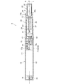
エアロゾル吸引器1は、燃焼を伴わずに香味を吸引するための器具であり、所定方向(以下、長手方向Aと呼ぶ)に沿って延びる棒形状を有する。エアロゾル吸引器1は、長手方向Aに沿って電源ユニット10と、第1カートリッジ20と、第2カートリッジ30と、がこの順に設けられている。第1カートリッジ20は、電源ユニット10に対して着脱可能であり、第2カートリッジ30は、第1カートリッジ20に対して着脱可能である。言い換えると、第1カートリッジ20及び第2カートリッジ30は、それぞれ交換可能である。
(Aerosol inhaler)
The
(電源ユニット)
本実施形態の電源ユニット10は、図3〜図6に示すように、円筒状の電源ユニットケース11の内部に電源12、充電器13、制御部50、各種センサ等を収容する。電源12は、充電可能な二次電池、電気二重層キャパシタ等であり、好ましくは、リチウムイオン電池である。
(Power supply unit)
As shown in FIGS. 3 to 6, the
電源ユニットケース11の長手方向Aの一端側(第1カートリッジ20側)に位置するトップ部11aには、放電端子41が設けられる。放電端子41は、トップ部11aの上面から第1カートリッジ20に向かって突出するように設けられ、第1カートリッジ20の負荷21と電気的に接続可能に構成される。
A
また、トップ部11aの上面には、放電端子41の近傍に、第1カートリッジ20の負荷21に空気を供給する空気供給部42が設けられている。
In addition, an
電源ユニットケース11の長手方向の他端側(第1カートリッジ20と反対側)に位置するボトム部11bには、電源12を充電可能な外部電源60(図6参照)と電気的に接続可能な充電端子43が設けられる。充電端子43は、ボトム部11bの側面に設けられ、USB端子、microUSB端子、Lightning(登録商標)端子の少なくとも1つが接続可能である。
The
なお、充電端子43は、外部電源60から送電される電力を非接触で受電可能な受電部であってもよい。このような場合、充電端子43(受電部)は、受電コイルから構成されていてもよい。非接触による電力伝送(Wireless Power Transfer)の方式は、電磁誘導型でもよいし、磁気共鳴型でもよい。また、充電端子43は、外部電源60から送電される電力を無接点で受電可能な受電部であってもよい。別の一例として、充電端子43は、USB端子、microUSB端子、Lightning(登録商標)端子の少なくとも1つが接続可能であり、且つ上述した受電部を有していてもよい。
The
即ち、電源ユニット10は、放電端子41と充電端子43とが別体に構成され、且つ、長手方向Aにおいて離間して配置されるので、充電端子43には、放電端子41を介した電源12の放電が可能な状態で、外部電源60を電気的に接続することができるように構成される。また、電源ユニット10では、充電端子43と外部電源60が電気的に接続されている状態で、エアロゾル生成要求を検出した場合、電源12の充電と放電とが同時に行われることが禁止される。
That is, in the
また、電源ユニットケース11には、ユーザが操作可能な操作部14が、トップ部11aの側面に充電端子43とは反対側を向くように設けられる。より詳述すると、操作部14と充電端子43は、操作部14と充電端子43を結ぶ直線と長手方向Aにおける電源ユニット10の中心線Lの交点について点対称の関係にある。操作部14は、ボタン式のスイッチ、タッチパネル等から構成され、ユーザの使用意思を反映して制御部50及び各種センサを起動/遮断する際等に利用される。操作部14の近傍には、制御部50及びパフ動作を検出する吸気センサ15が設けられている。
In the power
充電器13は、充電端子43から電源12へ入力される充電電力を制御する。充電器13は、充電端子43に接続される充電ケーブルに搭載された交流を直流に変換するインバータ61等からの直流を大きさの異なる直流に変換するコンバータ、電圧計、電流計、プロセッサ等を含む充電ICを用いて構成される。
The
制御部50は、図6に示すように、充電器13、操作部14、パフ(吸気)動作を検出する吸気センサ15、電源12の電圧を測定する電圧センサ16、温度センサ17等の各種センサ装置、及びパフ動作の回数又は負荷21への通電時間等を記憶するメモリ18に接続され、エアロゾル吸引器1の各種の制御を行う。吸気センサ15は、コンデンサマイクロフォンや圧力センサ等から構成されていてもよい。制御部50は、具体的にはプロセッサ(MCU:マイクロコントローラユニット)である。このプロセッサの構造は、より具体的には、半導体素子などの回路素子を組み合わせた電気回路である。制御部50の詳細については後述する。
As shown in FIG. 6, the
また、電源ユニットケース11には、内部に外気を取り込む不図示の空気取込口が設けられている。なお、空気取込口は、操作部14の周囲に設けられていてもよく、充電端子43の周囲に設けられていてもよい。
The power
(第1カートリッジ)
第1カートリッジ20は、図3に示すように、円筒状のカートリッジケース27の内部に、エアロゾル源22を貯留するリザーバ23と、エアロゾル源22を霧化する電気的な負荷21と、リザーバ23から負荷21へエアロゾル源を引き込むウィック24と、エアロゾル源22が霧化されることで発生したエアロゾルが第2カートリッジ30に向かって流れるエアロゾル流路25と、第2カートリッジ30の一部を収容するエンドキャップ26と、を備える。
(First cartridge)
As shown in FIG. 3, the
リザーバ23は、エアロゾル流路25の周囲を囲むように区画形成され、エアロゾル源22を貯留する。リザーバ23には、樹脂ウェブや綿等の多孔体が収容され、且つ、エアロゾル源22が多孔体に含浸されていてもよい。エアロゾル源22は、グリセリン、プロピレングリコール、水などの液体を含む。
The
ウィック24は、リザーバ23から毛管現象を利用してエアロゾル源22を負荷21へ引き込む液保持部材であって、例えば、ガラス繊維や多孔質セラミックなどによって構成される。
The
負荷21は、電源12から放電端子41を介して供給される電力によって燃焼を伴わずにエアロゾル源22を霧化する。負荷21は、所定ピッチで巻き回される電熱線(コイル)によって構成されている。なお、負荷21は、エアロゾル源22を霧化してエアロゾルを発生可能な素子であればよく、例えば、発熱素子、又は超音波発生器である。発熱素子としては、発熱抵抗体、セラミックヒータ、及び誘導加熱式のヒータ等が挙げられる。
The
エアロゾル流路25は、負荷21の下流側であって、電源ユニット10の中心線L上に設けられる。
The
エンドキャップ26は、第2カートリッジ30の一部を収容するカートリッジ収容部26aと、エアロゾル流路25とカートリッジ収容部26aとを連通させる連通路26bと、を備える。
The
(第2カートリッジ)
第2カートリッジ30は、香味源31を貯留する。第2カートリッジ30は、第1カートリッジ20側の端部が第1カートリッジ20のエンドキャップ26に設けられたカートリッジ収容部26aに着脱可能に収容される。第2カートリッジ30は、第1カートリッジ20側とは反対側の端部が、ユーザの吸口32となっている。なお、吸口32は、第2カートリッジ30と一体不可分に構成される場合に限らず、第2カートリッジ30と着脱可能に構成されてもよい。このように吸口32を電源ユニット10と第1カートリッジ20とは別体に構成することで、吸口32を衛生的に保つことができる。
(2nd cartridge)
The
第2カートリッジ30は、負荷21によってエアロゾル源22が霧化されることで発生したエアロゾルを香味源31に通すことによってエアロゾルに香味を付与する。香味源31を構成する原料片としては、刻みたばこ、たばこ原料を粒状に成形した成形体を用いることができる。香味源31は、たばこ以外の植物(例えば、ミント、漢方、ハーブ等)によって構成されてもよい。香味源31には、メントールなどの香料が付与されていてもよい。
The
本実施形態のエアロゾル吸引器1では、エアロゾル源22と香味源31と負荷21とによって、香味が付加されたエアロゾルを発生させることができる。つまり、エアロゾル源22と香味源31は、エアロゾルを発生させるエアロゾル生成源と言うことができる。
In the
エアロゾル吸引器1に用いられるエアロゾル生成源の構成は、エアロゾル源22と香味源31とが別体になっている構成の他、エアロゾル源22と香味源31とが一体的に形成されている構成、香味源31が省略されて香味源31に含まれ得る物質がエアロゾル源22に付加された構成、香味源31の代わりに薬剤等がエアロゾル源22に付加された構成等であってもよい。
The configuration of the aerosol generation source used in the
このように構成されたエアロゾル吸引器1では、図3中、矢印Bで示すように、電源ユニットケース11に設けられた不図示の取込口から流入した空気が、空気供給部42から第1カートリッジ20の負荷21付近を通過する。負荷21は、ウィック24によってリザーバ23から引き込まれたエアロゾル源22を霧化する。霧化されて発生したエアロゾルは、取込口から流入した空気と共にエアロゾル流路25を流れ、連通路26bを介して第2カートリッジ30に供給される。第2カートリッジ30に供給されたエアロゾルは、香味源31を通過することで香味が付与され、吸口32に供給される。
In the
また、エアロゾル吸引器1には、各種情報を報知する報知部45が設けられている(図5参照)。報知部45は、発光素子によって構成されていてもよく、振動素子によって構成されていてもよく、音出力素子によって構成されていてもよい。また、報知部45は、発光素子、振動素子及び音出力素子のうち、2以上の素子の組合せであってもよい。報知部45は、電源ユニット10、第1カートリッジ20、及び第2カートリッジ30のいずれに設けられてもよいが、電源ユニット10に設けられることが好ましい。例えば、操作部14の周囲が透光性を有し、LED等の発光素子によって発光するように構成される。
In addition, the
(電気回路)
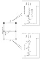
続いて、電源ユニット10の電気回路について図7を参照しながら説明する。
電源ユニット10は、電源12と、放電端子41を構成する正極側放電端子41a及び負極側放電端子41bと、充電端子43を構成する正極側充電端子43a及び負極側充電端子43bと、電源12の正極側と正極側放電端子41aとの間及び電源12の負極側と負極側放電端子41bとの間に接続される制御部50と、充電端子43と電源12との電力伝達経路上に配置される充電器13と、電源12と放電端子41との電力伝達経路上に配置されるスイッチ19と、後述する第1ツェナーダイオード71、第2ツェナーダイオード72、抵抗器73、第1コンデンサ74及び第2コンデンサ75と、を備える。スイッチ19は、例えばMOSFETにより構成され、制御部50がゲート電圧を調整することによって開閉制御される。
(electric circuit)
Subsequently, an electric circuit of the
The
(制御部)
制御部50は、図6に示すように、エアロゾル生成要求検出部51と、操作検出部52と、電力制御部53と、報知制御部54と、を備える。
(Control unit)
As shown in FIG. 6, the
エアロゾル生成要求検出部51は、吸気センサ15の出力結果に基づいてエアロゾル生成の要求を検出する。吸気センサ15は、吸口32を通じたユーザの吸引により生じた電源ユニット10内の圧力変化の値を出力するよう構成されている。吸気センサ15は、例えば、不図示の取込口から吸口32に向けて吸引される空気の流量(すなわち、ユーザのパフ動作)に応じて変化する気圧に応じた出力値(例えば、電圧値又は電流値)を出力する圧力センサである。
The aerosol generation
操作検出部52は、ユーザによる操作部14の操作を検出する。
The
報知制御部54は、各種情報を報知するように報知部45を制御する。例えば、報知制御部54は、第2カートリッジ30の交換タイミングの検出に応じて、第2カートリッジ30の交換タイミングを報知するように報知部45を制御する。報知制御部54は、メモリ18に記憶されたパフ動作の回数又は負荷21への累積通電時間に基づいて、第2カートリッジ30の交換タイミングを報知する。報知制御部54は、第2カートリッジ30の交換タイミングの報知に限らず、第1カートリッジ20の交換タイミングの報知、電源12の交換タイミング、電源12の充電タイミング等を報知してもよい。
The
電力制御部53は、エアロゾル生成要求検出部51がエアロゾル生成の要求を検出した際に放電端子41を介した電源12の放電を、スイッチ19のオン/オフによって制御する。
The
電力制御部53は、負荷21によってエアロゾル源が霧化されることで生成されるエアロゾルの量が所望範囲に収まるように、言い換えると、電源12から負荷21に供給される電力量が一定範囲となるように制御する。具体的に説明すると、電力制御部53は、例えば、PWM(Pulse Width Modulation:パルス幅変調)制御によってスイッチ19のオン/オフを制御する。これに代えて、電力制御部53は、PFM(Pulse Frequency Modulation:パルス周波数変調)制御によってスイッチ19のオン/オフを制御してもよい。
The
電力制御部53は、負荷21への電力供給を開始してから所定期間が経過した場合に、電源12から負荷21に対する電力供給を停止してもよい。言い換えると、電力制御部53は、ユーザが実際にパフ動作を行っているパフ期間内であっても、パフ期間が所定期間を超えた場合に、電源12から負荷21に対する電力供給を停止する。所定期間は、ユーザのパフ期間のばらつきを抑制するために定められる。電力制御部53は、電源12の蓄電量に応じて、1回のパフ動作におけるスイッチ19のオン/オフのデューティ比を制御する。例えば、電力制御部53は、電源12から負荷21に電力を供給するオン時間の間隔(パルス間隔)を制御したり、電源12から負荷21に電力を供給するオン時間の長さ(パルス幅)を制御したりする。
The
また、電力制御部53は、充電端子43と外部電源60との電気的な接続を検出し、充電器13を介した電源12の充電を制御する。
Further, the
(基板構成)
図5及び図7に示すように、電源ユニット10は、充電端子43、第2ツェナーダイオード72及び抵抗器73が設けられる第1回路基板76と、制御部50、充電器13、スイッチ19と、第1ツェナーダイオード71、第1コンデンサ74、第2コンデンサ75、操作部14及び吸気センサ15が設けられる第2回路基板77と、第1回路基板76と第2回路基板77とを電気的に接続する導電部材78と、を備える。導電部材78は、充電端子43と充電器13とを電気的に接続する導電部の一部であり、本実施形態の導電部材78は、フレキシブル回路基板を用いて構成されるが、導線で構成してもよい。
(Board configuration)
As shown in FIGS. 5 and 7, the
図5に示すように、第1回路基板76と第2回路基板77は、互いに離間して配置されている。具体的には、電源12の長さ方向(長手方向A)において一端側に第1回路基板76が設けられ、電源12の長さ方向(長手方向A)において他端側に第2回路基板77が設けられ、電源12の周面に沿って電源12の長さ方向に延在する導電部材78を介して第1回路基板76と第2回路基板77とが電気的に接続されている。なお、電源12の幅方向(長手方向Aに直交する方向)において一端側に第1回路基板76が設けられ、電源12の幅方向において他端側に第2回路基板77が設けられるようにしてもよい。
As shown in FIG. 5, the
(第1ツェナーダイオード)
第1ツェナーダイオード71は、充電端子43と充電器13との間において、充電器13に対して並列に接続される。このような第1ツェナーダイオード71によれば、充電器13に入力される電圧を安定化することができる。すなわち、ツェナーダイオードは、図8Bに示すように、逆方向へ流れる電流が急激に大きくなる(ダイオードが本来有する逆流防止作用が失われる)降伏電圧VBDが小さいため、容易に降伏状態となる。これにより、図8Aに示すように、ツェナーダイオードの両端の電圧がVBDに固定され、出力電圧Vout=VBDの関係が成り立つので、図8Cに示すように、入力電圧Vinに脈動があっても、図8Dに示すように、脈動が除去された安定した出力電圧Voutが得られる。
(First Zener diode)
The
なお、図8Aに示す回路では、ツェナーダイオードの両端に印加される電圧が降伏電圧未満の場合、出力電圧Voutは、入力電圧Vinと等しくなる点に留意されたい。 In the circuit shown in Figure 8A, when the voltage applied across the Zener diode is less than the breakdown voltage, the output voltage V out is to be noted that equal to the input voltage V in.
第1ツェナーダイオード71は、充電端子43の出力端より充電器13の入力端の方に近くなるように接続されている。このような第1ツェナーダイオード71によれば、充電端子43から供給される電圧の安定化のみならず、充電端子43と充電器13との間に不可避的に存在するL(リアクタンス)成分による電圧の脈動を除去し、充電器13を適切に保護できる。この不可避的に存在するL成分は、例えば導電部材78や抵抗器73によってもたらされる。
The
第1ツェナーダイオード71は、前述したように第2回路基板77に設けられる。つまり、充電端子43と充電器13が別々の回路基板76、77に設けられるので、電源ユニット10内における各部品のレイアウトの自由度が高い。また、充電器13が設けられる第2回路基板77に第1ツェナーダイオード71が設けられるので、第1ツェナーダイオード71を充電器13の近くに配置することができる。なお、第1ツェナーダイオード71は、第2回路基板77ではなく、充電端子43から入力される電力の流れ方向において、導電部材78の下流側に設けてもよい。このようにしても、第1ツェナーダイオード71を充電器13の近くに配置することができる。このように第1ツェナーダイオード71を充電器13の近くに配置すれば、第1ツェナーダイオード71によって脈動が除去された安定した電圧を充電器13へ入力することができる。
The
第1ツェナーダイオード71は、充電端子43と充電器13とを電気的に接続する母線79に直接接続される。すなわち、トランジスタ等のスイッチを介さずに第1ツェナーダイオード71が接続されているので、第1ツェナーダイオード71回りの構造の大型化を回避できる。さらに、エアロゾル吸引器1では、大電流や高電圧を扱わないため、トランジスタ等のスイッチに第1ツェナーダイオード71を接続しなくても、電圧を十分に安定化することができる。
(第2ツェナーダイオード)
第2ツェナーダイオード72は、充電端子43と第1ツェナーダイオード71との間において、第1ツェナーダイオード71に対して並列に接続される。これにより、外部電源から入力される電圧の揺らぎを第2ツェナーダイオード72で除去しつつ、充電端子43と充電器13との間に不可避的に存在するL成分による電圧の脈動を第1ツェナーダイオード71で除去することで、より確実に充電器13を保護することができる。また、第1ツェナーダイオード71と第2ツェナーダイオード72とで役割を分けることにより、ツェナーダイオードの大型化やコストの増加を抑制できる。併せて、1つツェナーダイオードに発熱が集中することが抑制できる。さらに、L成分は電圧や電流の時間変化に応答するため、L成分が発生する手前に配置された第2ツェナーダイオード72で外部電源から入力される電圧の揺らぎを除去しておくことで、充電器13により安定した電圧を印加できる。
(Second Zener diode)
The
なお、第2ツェナーダイオード72は、前述したように第1回路基板76に設けられ、第1ツェナーダイオード71は、第1回路基板76から離間する第2回路基板77に設けられるが、充電端子43から入力される電力の流れ方向において、導電部材78の上流側に第2ツェナーダイオード72を設け、充電端子43から入力される電力の流れ方向において、導電部材78の下流側に第1ツェナーダイオード71を設けるようにしてもよい。
The
第1ツェナーダイオード71及び第2ツェナーダイオード72は、同一部品で構成されている。このようにすると、部品の管理が容易になるとともに、ツェナーダイオードのコストを削減できる。
The
(ツェナー電圧)
続いて、第2ツェナーダイオード72及び第1ツェナーダイオード71として好適なツェナーダイオードの範囲(ツェナー電圧の範囲)について図9を参照して説明する。一般的なツェナーダイオードのツェナー電圧は、ある特定の値ではなく、最大値と最小値で区画される範囲で定義される。以下の説明では、第2ツェナーダイオード72を例に説明する。
(Zener voltage)
Next, a range of a zener diode (range of a zener voltage) suitable as the
第2ツェナーダイオード72のツェナー電圧の最大値は、充電器13の最大動作保証電圧(例えば、6.45V)より低い。このようにすると、充電器13に最大動作保証電圧以上の電圧が入力されることを回避でき、最大動作保証電圧より低い電圧を安定的に入力させることができる。
The maximum value of the Zener voltage of the
第2ツェナーダイオード72のツェナー電圧の最小値は、充電器13の最小動作保証電圧(例えば、4.45V)より高い。このようにすると、充電器13に動作保証電圧より低い電圧が入力されることを回避でき、最小動作保証電圧以上の電圧を安定的に入力させることができる。
The minimum value of the Zener voltage of the
充電器13の最大動作保証電圧から第2ツェナーダイオード72のツェナー電圧の最大値を減算した値は、第2ツェナーダイオード72のツェナー電圧の最小値から充電器13の最小動作保証電圧を減算した値より小さい。このようにすると、第2ツェナーダイオード72が降伏状態になる頻度を下げることができるので、第2ツェナーダイオード72の発熱を抑制できるとともに、第2ツェナーダイオード72を長寿命化できる。
The value obtained by subtracting the maximum value of the zener voltage of the
一般的なツェナーダイオードの抵抗値及び降伏状態においてツェナーダイオードを貫流する電流は決して小さくない。従って、降伏状態におけるツェナーダイオードの発熱は抑制されることが好ましい。また、充電器13へ入力されようとする電圧が充電器13の最大動作保証電圧よりも低い場合、ツェナーダイオードによる電圧の安定化は必須ではない。
In a general Zener diode, the resistance and the current flowing through the Zener diode in a breakdown state are not small. Therefore, it is preferable that heat generation of the Zener diode in the breakdown state is suppressed. When the voltage to be input to the
充電端子43から供給される電圧の定格値(例えば、5.0V)は、充電器13の最小動作保証電圧より高く、第2ツェナーダイオード72のツェナー電圧の最小値は、充電端子43から供給される電圧の定格値(定格電圧)より高い。このようにすると、第2ツェナーダイオード72が常時降伏状態とならないため、充電端子43から供給される電圧に対し第2ツェナーダイオード72を有効に活用することができる。
The rated value of the voltage supplied from the charging terminal 43 (for example, 5.0 V) is higher than the minimum operation guarantee voltage of the
充電器13の最大動作保証電圧から第2ツェナーダイオード72のツェナー電圧の最大値を減算した値は、第2ツェナーダイオード72のツェナー電圧の最小値から充電端子43から供給される電圧の定格値を減算した値より小さい。このようにすると、第2ツェナーダイオード72が降伏状態になる頻度を下げることができるので、第2ツェナーダイオード72の発熱を抑制できるとともに、第2ツェナーダイオード72を長寿命化できる。
The value obtained by subtracting the maximum value of the Zener voltage of the
ツェナーダイオードは、部品毎(図9のZ1〜Z5)にツェナー電圧の最大値とツェナー電圧の最小値とが決まっているため、上記したツェナー電圧範囲を有するツェナーダイオードを選択する。したがって、第2ツェナーダイオード72及び第1ツェナーダイオード71としては、部品Z2〜Z4が好ましく、部品Z2が最も好ましい。第2ツェナーダイオード72及び第1ツェナーダイオード71で、同一の部品を用いてもよく、異なる部品を用いてもよい。
Since the maximum value of the Zener voltage and the minimum value of the Zener voltage are determined for each component (Z1 to Z5 in FIG. 9), the Zener diode having the Zener voltage range described above is selected. Therefore, as the
なお、上述した実施形態においては充電器13に入力される電圧を安定化するために第2ツェナーダイオード72を用いたが、制御部50へ入力される電圧を安定化するためにさらに別のツェナーダイオードを用いてもよい。制御部50も充電器13と同様に最大動作保証電圧と最小動作保証電圧を持つため、これらに基づいて適切なツェナー電圧の範囲を持つツェナーダイオードを用いることができる。
In the above-described embodiment, the
(抵抗器)
抵抗器73は、第1ツェナーダイオード71と第2ツェナーダイオード72との間において、第1ツェナーダイオード71及び第2ツェナーダイオード72に対して直列に接続される。このようにすると、抵抗器73による電圧降下によって高い電圧が充電器13に入力されることを防止できる。さらに、ツェナー電圧以上の電圧が第1ツェナーダイオード71に印加されにくくなるため、第1ツェナーダイオード71における発熱を抑制することができる。
(Resistor)
The
抵抗器73は、充電端子43から入力される電力の流れ方向において、導電部材78より上流側に接続される。具体的には、充電器13が設けられる第2回路基板77から離間する第1回路基板76に抵抗器73が設けられる。このようにすると、発熱体である抵抗器73を充電器13から離すことができる。
The
(第1コンデンサ)
第1コンデンサ74は、充電端子43と充電器13との間において、充電器13に対して並列に接続される。このようにすると、第1コンデンサ74を平滑コンデンサとして機能させることにより、充電器13に入力される電圧を安定化することができる。また、第1コンデンサ74は、充電端子43と充電器13とのうち充電器13の方に近くなるように導電部に接続される。これにより、充電器13に入力される電圧をより安定化することができる。
(First capacitor)
The
充電端子43と充電器13とを電気的に接続する導電部の抵抗成分と第1コンデンサ74とによりローパスフィルタを構成するので、高周波のノイズが充電器13に入力されることを抑制できる。また、第1コンデンサ74は、第1ツェナーダイオード71と充電器13との間において、充電器13に対して並列に接続されるので、第1ツェナーダイオードで除去しきれない微小な電圧の変動を第1コンデンサ74で平滑化し、充電器13により安定した電圧を入力できる。なお、前述した抵抗器73を用いる場合は、抵抗器73もローパスフィルタの一部を構成する。
Since a low-pass filter is formed by the resistance component of the conductive portion that electrically connects the charging
因みに、平滑コンデンサは、図10に示すように、入力電圧Vinに含まれるリップル成分(脈動成分)をコンデンサの充電作用及び放電作用を利用して平滑化し、出力電圧Voutを安定化させる。また、ローパスフィルタは、図11に示すように、コンデンサ(C)及び抵抗成分(R)で構成され、高周波ノイズを除去し、低周波ノイズを通過させるフィルタである。ローパスフィルタにおけるカットオフ周波数f(この周波数以下を通過させる周波数)は、以下の式で表される。
f=1/2πRC
Incidentally, as shown in FIG. 10, the smoothing capacitor smoothes a ripple component (pulsation component) included in the input voltage Vin using a charging action and a discharging action of the capacitor, thereby stabilizing the output voltage Vout . Further, as shown in FIG. 11, the low-pass filter is composed of a capacitor (C) and a resistance component (R), and is a filter that removes high-frequency noise and passes low-frequency noise. The cut-off frequency f (frequency passing below this frequency) in the low-pass filter is expressed by the following equation.
f = 1 / 2πRC
第1コンデンサ74は、回路基板における占有面積を小さくするために、リップル成分を除去できる範囲で容量(体格)を小さくすることが好ましいが、第1コンデンサ74の容量を小さくすると、カットオフ周波数が高くなり、十分なノイズ除去性能を発揮できない可能性がある。そこで、本実施形態の電源ユニット10では、第1コンデンサ74の容量を小さくしつつ、抵抗成分を大きくすることで、カットオフ周波数を低く抑えて必要なノイズ除去性能を確保する。以下、抵抗成分を大きくするための構成を列挙する。
In order to reduce the area occupied by the circuit board, the
第1コンデンサ74は、前述したように充電器13と共に第2回路基板77に設けられる。第2回路基板77は、充電端子43が設けられる第1回路基板76から離間しており、導電部材78を介して第1回路基板76と電気的に接続される。つまり、第1コンデンサ74の上流側には、導電部材78が存在し、該導電部材78の抵抗成分でカットオフ周波数が低くなるので、ノイズ除去性能を向上させることができる。
The
第1回路基板76は、前述したように電源12の長さ方向(又は幅方向)において一端側に設けられ、第2回路基板77は、電源12の長さ方向(又は幅方向)において他端側に設けられる。つまり、第1回路基板76及び第2回路基板77が電源12の長さ方向(又は幅方向)において反対側に設けられるので、導電部材78の長さを確保することができ、その結果、導電部材78の抵抗成分を増やし、カットオフ周波数を低くできる。換言すれば、除去できるノイズの周波数帯を広くできる。
The
第1コンデンサ74の入力側、つまり第1コンデンサ74と充電端子43との間の導電部には、上記した抵抗器73が設けられている。この抵抗器73は、その抵抗成分によりカットオフ周波数を低下させるので、ノイズ除去性能を向上させることができる。また、抵抗器73による電圧降下によって、高い電圧が充電器13に入力されることを抑制できる。また、抵抗器は73、第1回路基板76に設けられるので、充電器13や制御部50が設けられる第2回路基板77の発熱量を下げることができる。
The
以上の構成により、抵抗成分を大きくすることで、カットオフ周波数を低く抑えて必要なノイズ除去性能を確保することができる。 With the above configuration, by increasing the resistance component, the cut-off frequency can be kept low and the required noise removal performance can be secured.
第1コンデンサ74の容量は、1μF以下とすることができる。このようにすると、エアロゾル吸引器用の電源ユニット10に必要十分な容量のコンデンサを選択することで、電源ユニット10の大型化を回避できる。
The capacity of the
また、第1コンデンサ74の容量は、0.1μF以下であることが好ましい。このようにすると、エアロゾル吸引器用の電源ユニット10に必要十分な容量のコンデンサを選択しつつ、電源ユニット10を小型化できる。
Further, the capacity of the
(第2コンデンサ)
第2コンデンサ75は、制御部50の入力側において、制御部50に対して並列に接続される。このようにすると、第2コンデンサ75を平滑コンデンサとして機能させることにより、制御部50に入力される電圧を安定化することができる。第2コンデンサ75も、第1コンデンサ74と同様に、充電端子43と制御部50とのうち制御部50の方に近くなるように導電部に接続される。これにより、制御部50に入力される電圧をより安定化することができる。
(Second capacitor)
The
第2コンデンサ75の容量は、第1コンデンサ74の容量と異なる。つまり、第1コンデンサ74と第2コンデンサ75は、保護すべき対象(充電器13、制御部50)が異なるので、保護対象に応じた適切な容量を持つコンデンサを選択することにより、基板上のコンデンサの占有面積を小さくできる。
The capacity of the
充電器13の最大動作保証電圧(例えば、6.45V)は、制御部50の最大動作保証電圧(例えば、5.5V)より高い。そのため、第2コンデンサ75としては、第1コンデンサ74より容量が大きいコンデンサが選択される。このように、耐電圧性能が低い制御部50の入力側に設けられる第2コンデンサ75の容量を、充電器13の入力側に設けられる第1コンデンサ74の容量に対して大きくすることで、耐電圧性能に劣る制御部50をより確実に保護することができる。
The maximum operation guarantee voltage (for example, 6.45 V) of the
充電器13は、電源12の充電を制御可能、且つ、電源12の充電時のみ動作するよう構成され、制御部50は、電源12の充電時及び放電時に動作するように構成される。そのため、第2コンデンサ75としては、第1コンデンサ74より容量が大きいコンデンサが選択される。このように、電源12の充電時及び放電時に動作する制御部50の入力側に設けられる第2コンデンサ75の容量を、充電時のみ動作する充電器13の入力側に設けられる第1コンデンサ74の容量に対して大きくすることで、利用頻度の高い重要な制御部50をより確実に保護することができる。
The
充電器13の制御周期(動作クロック)は、制御部50の制御周期より長い。そのため、第2コンデンサ75としては、第1コンデンサ74より容量が大きいコンデンサが選択される。このように、制御周期の短い制御部50の入力側に設けられる第2コンデンサ75の容量を、制御周期の長い充電器13の入力側に設けられる第1コンデンサ74の容量に対して大きくすることで、高性能な制御部50をより確実に保護することができる。
The control cycle (operation clock) of the
制御部50は、ユーザが操作可能な操作部14と、ユーザの吸引動作を検出する吸気センサ15とに電気的に接続されている。そのため、第2コンデンサ75としては、第1コンデンサ74より容量が大きいコンデンサが選択される。このようにすると、操作部14や吸気センサ15が電気的に接続される制御部50の入力側に設けられる第2コンデンサ75の容量を第1コンデンサ74に対して大きくすることで、操作部14や吸気センサ15を経由して侵入する静電ノイズの影響を受けやすい制御部50をより確実に保護することができる。
The
第1コンデンサ74の入力側には、第1コンデンサ74に対して並列に接続される第1ツェナーダイオード71が設けられる。そのため、第1コンデンサ74の容量を第2コンデンサ75の容量に対して小さくしたとしても、第1ツェナーダイオード71の定電圧化作用によって充電器13を保護することができる。
On the input side of the
第2コンデンサ75の容量は、第1コンデンサ74の容量の10〜100倍であることが好ましい。例えば、第2コンデンサ75の容量は、第1コンデンサ74の容量を0.1μF、第2コンデンサ75の容量を10μFとする。このように、保護対象に応じた適切な容量を持つコンデンサを実装することで、保護対象を保護しつつ、基板上のコンデンサの占有面積を小さくできる。
The capacity of the
(第2回路基板の配置構成)
図3及び図5に示すように、操作部14及び吸気センサ15は、第2回路基板77に設けられる。操作部14や吸気センサ15を経由して侵入する静電気等の静電ノイズは、第2回路基板77に設けられるコンデンサ74、75で平滑化される。
(Arrangement configuration of second circuit board)
As shown in FIGS. 3 and 5, the
第2回路基板77は、第1主面77aと、第1主面77aの裏面である第2主面77bと、を備え、操作部14は第1主面77aに設けられ、吸気センサ15は第2主面77bに設けられる。このように、操作部14と吸気センサ15が第2回路基板77の異なる面に設けられるので、操作部14を経由して侵入する静電ノイズと吸気センサ15を経由して侵入する静電ノイズが重畳されて、大きなノイズになることを抑制できる。
The
コンデンサ74、75は、第2回路基板77の第2主面77bに設けられる。即ち、第2主面77bが回路実装面である。このように、コンデンサ74、75と操作部14を第2回路基板77の異なる面に設けることで、コンデンサ74、75を配置するスペースを確保することができる。
The
操作部14はその役割上、電源ユニット10の表面に露出する必要があるため、静電ノイズの侵入経路となりやすい。コンデンサ74、75が設けられる第2主面77bでこの静電ノイズを直接受けるのではなく、第1主面77aで受けることで、第2主面77bに到達し得る静電ノイズを低減できる。従って、大きな容量を持つコンデンサが不要になるため、基板上のコンデンサの占有面積を小さくできる。
Since the
なお、本発明は、上記した実施形態に限らず、適宜、変形、改良、等が可能である。
例えば、上記した実施形態の電源ユニット10は、第1ツェナーダイオード71及び第2ツェナーダイオード72を備えるが、いずれか一方であってもよい。
また、上記した実施形態では、充電器13の動作保証電圧を基準として第1ツェナーダイオード71及び第2ツェナーダイオード72の適切なツェナー電圧の範囲を規定しているが、制御部50の動作保証電圧を基準として第1ツェナーダイオード71及び第2ツェナーダイオード72の適切なツェナー電圧の範囲を規定してもよい。
The present invention is not limited to the above-described embodiment, but can be appropriately modified, improved, and the like.
For example, the
In the above-described embodiment, the appropriate Zener voltage range of the
本明細書には少なくとも以下の事項が記載されている。なお、括弧内には、上記した実施形態において対応する構成要素等を示しているが、これに限定されるものではない。 At least the following matters are described in this specification. In addition, although the corresponding components in the above-described embodiment are shown in parentheses, the present invention is not limited to this.
(1)
エアロゾル源(エアロゾル源22)からエアロゾルを発生させるための負荷(負荷21)へ放電可能な電源(電源12)と、
外部電源(外部電源60)と電気的に接続可能なコネクタ(充電端子43)と、
前記電源の充電と放電の少なくとも一方を制御するよう構成される、又は、前記コネクタから入力される電力を前記電源の充電電力へ変換可能に構成される制御装置(制御部50、充電器13)と、を備えるエアロゾル吸引器(エアロゾル吸引器1)用の電源ユニット(電源ユニット10)であって、
前記電源ユニットは、
前記コネクタと前記制御装置との間に、前記制御装置に対し並列接続されるツェナーダイオード(第1ツェナーダイオード71、第2ツェナーダイオード72)をさらに備え、
前記ツェナーダイオードのツェナー電圧の最大値は、前記制御装置の最大動作保証電圧より低い、エアロゾル吸引器用の電源ユニット。
(1)
A power supply (power supply 12) capable of discharging from an aerosol source (aerosol source 22) to a load (load 21) for generating aerosol;
A connector (charging terminal 43) electrically connectable to an external power supply (external power supply 60);
A control device configured to control at least one of charging and discharging of the power supply, or configured to convert power input from the connector into charging power of the power supply (
The power supply unit,
A zener diode (
A power supply unit for an aerosol inhaler, wherein a maximum value of a Zener voltage of the Zener diode is lower than a maximum operation guarantee voltage of the control device.
(1)によれば、電源ユニットはコネクタと制御装置との間に制御装置に対し並列接続されるツェナーダイオードを備えるので、制御装置に入力される電圧を安定化することができる。また、ツェナーダイオードのツェナー電圧の最大値は、制御装置の最大動作保証電圧より低いので、制御装置に最大動作保証電圧以上の電圧が入力されることを回避でき、最大動作保証電圧より低い電圧を安定的に入力させることができる。 According to (1), since the power supply unit includes the zener diode connected in parallel with the control device between the connector and the control device, the voltage input to the control device can be stabilized. In addition, since the maximum value of the Zener voltage of the Zener diode is lower than the maximum operation guarantee voltage of the control device, it is possible to avoid inputting a voltage higher than the maximum operation guarantee voltage to the control device, and to reduce the voltage lower than the maximum operation guarantee voltage. It is possible to input stably.
(2)
(1)に記載のエアロゾル吸引器用の電源ユニットであって、
前記ツェナーダイオードの前記ツェナー電圧の最小値は、前記制御装置の最小動作保証電圧より高い、エアロゾル吸引器用の電源ユニット。
(2)
A power supply unit for an aerosol inhaler according to (1),
The power supply unit for an aerosol inhaler, wherein a minimum value of the zener voltage of the zener diode is higher than a minimum operation guarantee voltage of the control device.
(2)によれば、ツェナーダイオードのツェナー電圧の最小値は、制御装置の最小動作保証電圧より高いので、制御装置に動作保証電圧より低い電圧が入力されることを回避でき、最小動作保証電圧以上の電圧を安定的に入力させることができる。 According to (2), since the minimum value of the Zener voltage of the Zener diode is higher than the minimum operation guarantee voltage of the control device, it is possible to avoid inputting a voltage lower than the operation guarantee voltage to the control device, and the minimum operation guarantee voltage. The above voltage can be input stably.
(3)
(2)に記載のエアロゾル吸引器用の電源ユニットであって、
前記制御装置の前記最大動作保証電圧から前記ツェナーダイオードの前記ツェナー電圧の前記最大値を減算した値は、前記ツェナーダイオードの前記ツェナー電圧の前記最小値から前記制御装置の前記最小動作保証電圧を減算した値より小さい、エアロゾル吸引器用の電源ユニット。
(3)
A power supply unit for an aerosol inhaler according to (2),
A value obtained by subtracting the maximum value of the Zener voltage of the Zener diode from the maximum operation guarantee voltage of the control device is obtained by subtracting the minimum operation guarantee voltage of the control device from the minimum value of the Zener voltage of the Zener diode. Power supply unit for aerosol inhaler smaller than the specified value.
(3)によれば、制御装置の最大動作保証電圧からツェナーダイオードのツェナー電圧の最大値を減算した値は、ツェナーダイオードのツェナー電圧の最小値から制御装置の最小動作保証電圧を減算した値より小さいので、ツェナーダイオードが降伏状態になる頻度を下げることができる。これにより、ツェナーダイオードの発熱を抑制できるとともに、ツェナーダイオードを長寿命化できる。 According to (3), the value obtained by subtracting the maximum value of the Zener voltage of the Zener diode from the maximum operation guarantee voltage of the control device is obtained by subtracting the minimum operation guarantee voltage of the control device from the minimum value of the Zener voltage of the Zener diode. Since it is small, the frequency at which the Zener diode enters a breakdown state can be reduced. Thereby, the heat generation of the Zener diode can be suppressed, and the life of the Zener diode can be extended.
(4)
(1)に記載のエアロゾル吸引器用の電源ユニットであって、
前記コネクタから供給される電圧の定格値は、前記制御装置の最小動作保証電圧より高く、
前記ツェナーダイオードの前記ツェナー電圧の最小値は、前記定格値より高い、エアロゾル吸引器用の電源ユニット。
(4)
A power supply unit for an aerosol inhaler according to (1),
The rated value of the voltage supplied from the connector is higher than the minimum operation guarantee voltage of the control device,
A power supply unit for an aerosol inhaler, wherein a minimum value of the Zener voltage of the Zener diode is higher than the rated value.
(4)によれば、ツェナーダイオードのツェナー電圧の最小値は、制御装置の最小動作保証電圧より高く、且つコネクタから供給される電圧の定格値より高いので、コネクタから供給される電圧に対しツェナーダイオードを有効に活用することができる。 According to (4), the minimum value of the Zener voltage of the Zener diode is higher than the minimum operation guarantee voltage of the control device and higher than the rated value of the voltage supplied from the connector. The diode can be used effectively.
(5)
(4)に記載のエアロゾル吸引器用の電源ユニットであって、
前記制御装置の前記最大動作保証電圧から前記ツェナーダイオードの前記ツェナー電圧の前記最大値を減算した値は、前記ツェナーダイオードの前記ツェナー電圧の前記最小値から前記コネクタから供給される電圧の前記定格値を減算した値より小さい、エアロゾル吸引器用の電源ユニット。
(5)
A power supply unit for an aerosol inhaler according to (4),
The value obtained by subtracting the maximum value of the zener voltage of the zener diode from the maximum operation guarantee voltage of the control device is the rated value of the voltage supplied from the connector from the minimum value of the zener voltage of the zener diode. Power supply unit for aerosol inhaler, smaller than the value obtained by subtracting.
(5)によれば、制御装置の最大動作保証電圧からツェナーダイオードのツェナー電圧の最大値を減算した値は、ツェナーダイオードのツェナー電圧の最小値からコネクタから供給される電圧の定格値を減算した値より小さいので、ツェナーダイオードが降伏状態になる頻度を下げることができる。これにより、ツェナーダイオードの発熱を抑制できるとともに、ツェナーダイオードを長寿命化できる。 According to (5), the value obtained by subtracting the maximum value of the Zener voltage of the Zener diode from the maximum operation guarantee voltage of the control device is obtained by subtracting the rated value of the voltage supplied from the connector from the Minimum value of the Zener voltage of the Zener diode. Since it is smaller than the value, the frequency of the breakdown of the Zener diode can be reduced. Thereby, the heat generation of the Zener diode can be suppressed, and the life of the Zener diode can be extended.
(6)
(1)〜(5)のいずれかに記載のエアロゾル吸引器用の電源ユニットであって、
前記電源ユニットは、
前記コネクタが設けられる第1回路基板(第1回路基板76)と、
前記制御装置が設けられ、且つ、前記第1回路基板から離間した第2回路基板(第2回路基板77)と、をさらに備え、
前記ツェナーダイオードは、前記第1回路基板に設けられる、エアロゾル吸引器用の電源ユニット。
(6)
A power supply unit for an aerosol inhaler according to any one of (1) to (5),
The power supply unit,
A first circuit board (first circuit board 76) on which the connector is provided;
A second circuit board (second circuit board 77) provided with the control device and separated from the first circuit board;
The power supply unit for an aerosol inhaler, wherein the Zener diode is provided on the first circuit board.
(6)によれば、コネクタと制御装置が別々の回路基板に設けられるので、レイアウトの自由度が高い。また、2つの回路基板の間に存在する不可避のL成分は、電圧や電流の時間変化に応答するが、L成分の手前に配置されたツェナーダイオードで電圧の揺らぎを除去することで、より確実に制御装置を保護することができる。 According to (6), since the connector and the control device are provided on different circuit boards, the degree of freedom in layout is high. The unavoidable L component existing between the two circuit boards responds to the time change of the voltage and the current. However, by removing the fluctuation of the voltage by the zener diode disposed before the L component, the L component can be more reliably determined. The control device can be protected.
(7)
(6)に記載のエアロゾル吸引器用の電源ユニットであって、
前記電源ユニットは、
前記第1回路基板に設けられ、前記コネクタ及び前記ツェナーダイオードに対し直列に接続される抵抗器(抵抗器73)をさらに備える、エアロゾル吸引器用の電源ユニット。
(7)
A power supply unit for an aerosol inhaler according to (6),
The power supply unit,
A power supply unit for an aerosol inhaler, further comprising a resistor (resistor 73) provided on the first circuit board and connected in series to the connector and the zener diode.
(7)によれば、電源ユニットには、第1回路基板に設けられ、コネクタ及びツェナーダイオードに対し直列に接続される抵抗器が設けられるので、抵抗器による電圧降下によって高い電圧が制御装置に入力されるのを防止できる。 According to (7), since the resistor provided on the first circuit board and connected in series to the connector and the Zener diode is provided in the power supply unit, a high voltage is applied to the control device by a voltage drop caused by the resistor. Input can be prevented.
(8)
(7)に記載のエアロゾル吸引器用の電源ユニットであって、
前記抵抗器は、前記制御装置と前記ツェナーダイオードとの間に接続される、エアロゾル吸引器用の電源ユニット。
(8)
A power supply unit for an aerosol inhaler according to (7),
A power unit for an aerosol inhaler, wherein the resistor is connected between the control device and the Zener diode.
(8)によれば、抵抗器は、制御装置とツェナーダイオードとの間に接続されるので、ツェナーダイオードによって安定化された電圧を抵抗器でさらに電圧降下させることができることで、制御装置により安全な電圧を入力することができる。 According to (8), since the resistor is connected between the control device and the Zener diode, the voltage stabilized by the Zener diode can be further dropped by the resistor, so that the control device is safer. Voltage can be input.
(9)
(6)〜(8)のいずれかに記載のエアロゾル吸引器用の電源ユニットであって、
前記電源ユニットは、
前記第1回路基板と前記第2回路基板とを電気的に接続する導電部材(導電部材78)をさらに備える、エアロゾル吸引器用の電源ユニット。
(9)
A power supply unit for an aerosol inhaler according to any one of (6) to (8),
The power supply unit,
A power supply unit for an aerosol inhaler, further comprising a conductive member (conductive member 78) for electrically connecting the first circuit board and the second circuit board.
(9)によれば、電源ユニットには、第1回路基板と第2回路基板とを電気的に接続する導電部材が設けられるので、導電部材による電圧降下によって高い電圧が制御装置に入力されるのを防止できる。 According to (9), since the power supply unit is provided with the conductive member that electrically connects the first circuit board and the second circuit board, a high voltage is input to the control device by a voltage drop due to the conductive member. Can be prevented.
(10)
(6)〜(9)のいずれかに記載のエアロゾル吸引器用の電源ユニットであって、
前記電源ユニットは、
前記ツェナーダイオードと前記制御装置との間に、前記制御装置に対し並列接続されるコンデンサ(第1コンデンサ74、第2コンデンサ75)をさらに備える、エアロゾル吸引器用の電源ユニット。
(10)
(6) A power supply unit for an aerosol inhaler according to any one of (9) to (9),
The power supply unit,
A power supply unit for an aerosol inhaler, further comprising a capacitor (a
(10)によれば、電源ユニットは、ツェナーダイオードと制御装置との間に制御装置に対し並列接続されるコンデンサをさらに備えるので、ツェナーダイオードで除去しきれない微小な電圧の変動を平滑化でき、制御装置をより適切に保護することができる。 According to (10), since the power supply unit further includes a capacitor connected in parallel with the control device between the zener diode and the control device, it is possible to smooth a minute voltage fluctuation that cannot be completely removed by the zener diode. Thus, the control device can be more appropriately protected.
(11)
(10)に記載のエアロゾル吸引器用の電源ユニットであって、
前記コンデンサは、前記第2回路基板に設けられる、エアロゾル吸引器用の電源ユニット。
(11)
A power supply unit for an aerosol inhaler according to (10),
The power supply unit for an aerosol inhaler, wherein the capacitor is provided on the second circuit board.
(11)によれば、コンデンサは第2回路基板に設けられるので、ツェナーダイオード、コンデンサ、及び制御装置を第2回路基板に集約できる。 According to (11), since the capacitor is provided on the second circuit board, the Zener diode, the capacitor, and the control device can be integrated on the second circuit board.
1 エアロゾル吸引器
10 電源ユニット
12 電源
13 充電器(制御装置)
21 負荷
22 エアロゾル源
43 充電端子(コネクタ)
50 制御部(制御装置)
60 外部電源
71 第1ツェナーダイオード(ツェナーダイオード)
72 第2ツェナーダイオード(ツェナーダイオード)
73 抵抗器
74 第1コンデンサ(コンデンサ)
75 第2コンデンサ(コンデンサ)
76 第1回路基板
77 第2回路基板
78 導電部材
DESCRIPTION OF
21
50 control unit (control device)
60
72 Second Zener diode (Zener diode)
73
75 Second capacitor (capacitor)
76
Claims (8)
外部電源と電気的に接続可能なコネクタと、
前記電源の充電と放電の少なくとも一方を制御するよう構成される、又は、前記コネクタから入力される電力を前記電源の充電電力へ変換可能に構成される制御装置と、
前記コネクタと前記制御装置との間に、前記制御装置に対し並列接続されるツェナーダイオードと、を備えるエアロゾル吸引器用の電源ユニットであって、
前記ツェナーダイオードのツェナー電圧の最大値は、前記制御装置の最大動作保証電圧より低く、
前記ツェナーダイオードの前記ツェナー電圧の最小値は、前記制御装置の最小動作保証電圧より高く、
前記制御装置の前記最大動作保証電圧から前記ツェナーダイオードの前記ツェナー電圧の前記最大値を減算した値は、前記ツェナーダイオードの前記ツェナー電圧の前記最小値から前記制御装置の前記最小動作保証電圧を減算した値より小さい、エアロゾル吸引器用の電源ユニット。 A power supply capable of discharging from an aerosol source to a load for generating aerosol,
A connector electrically connectable to an external power supply,
A control device configured to control at least one of charging and discharging of the power supply, or configured to be able to convert power input from the connector into charging power of the power supply,
A power supply unit for an aerosol inhaler, comprising: a zener diode connected in parallel to the control device between the connector and the control device ;
The maximum value of the Zener voltage before Symbol Zener diode, rather low than the maximum guaranteed operating voltage of the control device,
The minimum value of the Zener voltage of the Zener diode is higher than the minimum operation guarantee voltage of the control device,
A value obtained by subtracting the maximum value of the Zener voltage of the Zener diode from the maximum operation guarantee voltage of the control device is obtained by subtracting the minimum operation guarantee voltage of the control device from the minimum value of the Zener voltage of the Zener diode. Power supply unit for aerosol inhaler smaller than the specified value .
外部電源と電気的に接続可能なコネクタと、
前記電源の充電と放電の少なくとも一方を制御するよう構成される、又は、前記コネクタから入力される電力を前記電源の充電電力へ変換可能に構成される制御装置と、
前記コネクタと前記制御装置との間に、前記制御装置に対し並列接続されるツェナーダイオードと、を備えるエアロゾル吸引器用の電源ユニットであって、
前記ツェナーダイオードのツェナー電圧の最大値は、前記制御装置の最大動作保証電圧より低く、
前記コネクタから供給される電圧の定格値は、前記制御装置の最小動作保証電圧より高く、
前記ツェナーダイオードの前記ツェナー電圧の最小値は、前記定格値より高く、
前記制御装置の前記最大動作保証電圧から前記ツェナーダイオードの前記ツェナー電圧の前記最大値を減算した値は、前記ツェナーダイオードの前記ツェナー電圧の前記最小値から前記コネクタから供給される電圧の前記定格値を減算した値より小さい、エアロゾル吸引器用の電源ユニット。 A power supply capable of discharging from an aerosol source to a load for generating aerosol,
A connector electrically connectable to an external power supply,
A control device configured to control at least one of charging and discharging of the power supply, or configured to be able to convert power input from the connector into charging power of the power supply,
A power supply unit for an aerosol inhaler, comprising: a zener diode connected in parallel to the control device between the connector and the control device;
The maximum value of the Zener voltage of the Zener diode is lower than the maximum operation guarantee voltage of the control device,
The rated value of the voltage supplied from the connector is higher than the minimum operation guarantee voltage of the control device,
The minimum value of the Zener voltage of the Zener diode is higher than the rated value,
The value obtained by subtracting the maximum value of the zener voltage of the zener diode from the maximum operation guarantee voltage of the control device is the rated value of the voltage supplied from the connector from the minimum value of the zener voltage of the zener diode. Power supply unit for aerosol inhaler, smaller than the value obtained by subtracting.
前記電源ユニットは、
前記コネクタが設けられる第1回路基板と、
前記制御装置が設けられ、且つ、前記第1回路基板から離間した第2回路基板と、をさらに備え、
前記ツェナーダイオードは、前記第1回路基板に設けられる、エアロゾル吸引器用の電源ユニット。 A power supply unit for an aerosol inhaler according to claim 1 or 2 ,
The power supply unit,
A first circuit board on which the connector is provided;
A second circuit board provided with the control device and separated from the first circuit board;
The power supply unit for an aerosol inhaler, wherein the Zener diode is provided on the first circuit board.
前記電源ユニットは、
前記第1回路基板に設けられ、前記コネクタ及び前記ツェナーダイオードに対し直列に接続される抵抗器をさらに備える、エアロゾル吸引器用の電源ユニット。 A power supply unit for an aerosol inhaler according to claim 3 , wherein
The power supply unit,
A power supply unit for an aerosol inhaler, further comprising a resistor provided on the first circuit board and connected in series to the connector and the zener diode.
前記抵抗器は、前記制御装置と前記ツェナーダイオードとの間に接続される、エアロゾル吸引器用の電源ユニット。 A power supply unit for an aerosol inhaler according to claim 4 , wherein
A power unit for an aerosol inhaler, wherein the resistor is connected between the control device and the Zener diode.
前記電源ユニットは、
前記第1回路基板と前記第2回路基板とを電気的に接続する導電部材をさらに備える、エアロゾル吸引器用の電源ユニット。 A power supply unit for an aerosol inhaler according to any one of claims 3 to 5 ,
The power supply unit,
A power supply unit for an aerosol inhaler, further comprising a conductive member that electrically connects the first circuit board and the second circuit board.
前記電源ユニットは、
前記ツェナーダイオードと前記制御装置との間に、前記制御装置に対し並列接続されるコンデンサをさらに備える、エアロゾル吸引器用の電源ユニット。 A power supply unit for an aerosol inhaler according to any one of claims 3 to 6 ,
The power supply unit,
A power supply unit for an aerosol inhaler, further comprising a capacitor between the zener diode and the control device, the capacitor being connected in parallel to the control device.
前記コンデンサは、前記第2回路基板に設けられる、エアロゾル吸引器用の電源ユニット。 A power supply unit for an aerosol inhaler according to claim 7 ,
The power supply unit for an aerosol inhaler, wherein the capacitor is provided on the second circuit board.
Priority Applications (9)
| Application Number | Priority Date | Filing Date | Title |
|---|---|---|---|
| EA202090073A EA036563B1 (en) | 2019-01-17 | 2020-01-16 | Power supply unit for an aerosol inhaler |
| KR1020200005738A KR102156176B1 (en) | 2019-01-17 | 2020-01-16 | Power supply unit for aerosol inhaler |
| CA3068699A CA3068699C (en) | 2019-01-17 | 2020-01-16 | Power supply unit for aerosol inhaler |
| CN202010052001.6A CN111436658B (en) | 2019-01-17 | 2020-01-17 | Power supply unit for aerosol inhaler |
| EP20152494.9A EP3683923B1 (en) | 2019-01-17 | 2020-01-17 | Power supply unit for aerosol inhaler |
| EP21200472.5A EP3965258A1 (en) | 2019-01-17 | 2020-01-17 | Power supply unit for aerosol inhaler |
| TW109101765A TWI724756B (en) | 2019-01-17 | 2020-01-17 | Power supply unit for aerosol inhaler |
| US16/745,484 US11005282B2 (en) | 2019-01-17 | 2020-01-17 | Power supply unit for aerosol inhaler |
| US17/230,183 US11699914B2 (en) | 2019-01-17 | 2021-04-14 | Power supply unit for aerosol inhaler provided with zener diode connected in parallel with charger |
Applications Claiming Priority (2)
| Application Number | Priority Date | Filing Date | Title |
|---|---|---|---|
| US201962793551P | 2019-01-17 | 2019-01-17 | |
| US62/793,551 | 2019-01-17 |
Related Child Applications (1)
| Application Number | Title | Priority Date | Filing Date |
|---|---|---|---|
| JP2019223155A Division JP6688934B1 (en) | 2019-01-17 | 2019-12-10 | Power supply unit for aerosol inhalers |
Publications (2)
| Publication Number | Publication Date |
|---|---|
| JP6633788B1 true JP6633788B1 (en) | 2020-01-22 |
| JP2020114196A JP2020114196A (en) | 2020-07-30 |
Family
ID=67539840
Family Applications (17)
| Application Number | Title | Priority Date | Filing Date |
|---|---|---|---|
| JP2019035974A Active JP6608082B1 (en) | 2019-01-17 | 2019-02-28 | Power supply unit for aerosol inhaler |
| JP2019035995A Active JP6573737B1 (en) | 2019-01-17 | 2019-02-28 | Power supply unit for aerosol inhaler |
| JP2019035990A Active JP6608083B1 (en) | 2019-01-17 | 2019-02-28 | Power supply unit for aerosol inhaler |
| JP2019035978A Active JP6557433B1 (en) | 2019-01-17 | 2019-02-28 | Power supply unit for aerosol inhaler |
| JP2019035984A Active JP6647435B1 (en) | 2019-01-17 | 2019-02-28 | Power supply unit for aerosol inhaler |
| JP2019035994A Active JP6647436B1 (en) | 2019-01-17 | 2019-02-28 | Power supply unit for aerosol inhaler, control method and program for power supply unit for aerosol inhaler |
| JP2019035981A Active JP6633788B1 (en) | 2019-01-17 | 2019-02-28 | Power supply unit for aerosol inhaler |
| JP2019185978A Active JP6640422B1 (en) | 2019-01-17 | 2019-10-09 | Power supply unit for aerosol inhaler |
| JP2019185979A Active JP6713082B1 (en) | 2019-01-17 | 2019-10-09 | Power supply unit for aerosol inhalers |
| JP2019223155A Active JP6688934B1 (en) | 2019-01-17 | 2019-12-10 | Power supply unit for aerosol inhalers |
| JP2019233379A Active JP7359685B2 (en) | 2019-01-17 | 2019-12-24 | Power supply unit for aerosol inhaler |
| JP2020003746A Active JP6678284B1 (en) | 2019-01-17 | 2020-01-14 | Power supply unit for aerosol inhaler, control method and program for power supply unit for aerosol inhaler |
| JP2020044751A Active JP7379225B2 (en) | 2019-01-17 | 2020-03-13 | Power supply unit for aerosol inhaler, control method and program for power supply unit for aerosol inhaler |
| JP2020094868A Active JP6959402B2 (en) | 2019-01-17 | 2020-05-29 | Power supply unit for aerosol aspirator and aerosol aspirator |
| JP2021165635A Active JP7087183B2 (en) | 2019-01-17 | 2021-10-07 | Aerosol aspirator |
| JP2022093077A Pending JP2022118063A (en) | 2019-01-17 | 2022-06-08 | Power supply unit for aerosol inhaler |
| JP2024002037A Pending JP2024028436A (en) | 2019-01-17 | 2024-01-10 | Power supply unit for aerosol inhaler |
Family Applications Before (6)
| Application Number | Title | Priority Date | Filing Date |
|---|---|---|---|
| JP2019035974A Active JP6608082B1 (en) | 2019-01-17 | 2019-02-28 | Power supply unit for aerosol inhaler |
| JP2019035995A Active JP6573737B1 (en) | 2019-01-17 | 2019-02-28 | Power supply unit for aerosol inhaler |
| JP2019035990A Active JP6608083B1 (en) | 2019-01-17 | 2019-02-28 | Power supply unit for aerosol inhaler |
| JP2019035978A Active JP6557433B1 (en) | 2019-01-17 | 2019-02-28 | Power supply unit for aerosol inhaler |
| JP2019035984A Active JP6647435B1 (en) | 2019-01-17 | 2019-02-28 | Power supply unit for aerosol inhaler |
| JP2019035994A Active JP6647436B1 (en) | 2019-01-17 | 2019-02-28 | Power supply unit for aerosol inhaler, control method and program for power supply unit for aerosol inhaler |
Family Applications After (10)
| Application Number | Title | Priority Date | Filing Date |
|---|---|---|---|
| JP2019185978A Active JP6640422B1 (en) | 2019-01-17 | 2019-10-09 | Power supply unit for aerosol inhaler |
| JP2019185979A Active JP6713082B1 (en) | 2019-01-17 | 2019-10-09 | Power supply unit for aerosol inhalers |
| JP2019223155A Active JP6688934B1 (en) | 2019-01-17 | 2019-12-10 | Power supply unit for aerosol inhalers |
| JP2019233379A Active JP7359685B2 (en) | 2019-01-17 | 2019-12-24 | Power supply unit for aerosol inhaler |
| JP2020003746A Active JP6678284B1 (en) | 2019-01-17 | 2020-01-14 | Power supply unit for aerosol inhaler, control method and program for power supply unit for aerosol inhaler |
| JP2020044751A Active JP7379225B2 (en) | 2019-01-17 | 2020-03-13 | Power supply unit for aerosol inhaler, control method and program for power supply unit for aerosol inhaler |
| JP2020094868A Active JP6959402B2 (en) | 2019-01-17 | 2020-05-29 | Power supply unit for aerosol aspirator and aerosol aspirator |
| JP2021165635A Active JP7087183B2 (en) | 2019-01-17 | 2021-10-07 | Aerosol aspirator |
| JP2022093077A Pending JP2022118063A (en) | 2019-01-17 | 2022-06-08 | Power supply unit for aerosol inhaler |
| JP2024002037A Pending JP2024028436A (en) | 2019-01-17 | 2024-01-10 | Power supply unit for aerosol inhaler |
Country Status (10)
| Country | Link |
|---|---|
| US (12) | US11031801B2 (en) |
| EP (10) | EP4033636A1 (en) |
| JP (17) | JP6608082B1 (en) |
| KR (8) | KR102194549B1 (en) |
| CN (8) | CN111463844A (en) |
| CA (7) | CA3068386C (en) |
| EA (8) | EA202193036A2 (en) |
| HU (1) | HUE061004T2 (en) |
| PL (2) | PL3683918T3 (en) |
| TW (8) | TWI720786B (en) |
Cited By (3)
| Publication number | Priority date | Publication date | Assignee | Title |
|---|---|---|---|---|
| CN113303521A (en) * | 2020-02-25 | 2021-08-27 | 日本烟草产业株式会社 | Power supply unit for aerosol inhaler and aerosol inhaler |
| US11246351B2 (en) | 2020-07-09 | 2022-02-15 | Japan Tobacco Inc. | Power supply unit for aerosol generation device |
| WO2023281715A1 (en) | 2021-07-08 | 2023-01-12 | 日本たばこ産業株式会社 | Power supply unit for aerosol generation device |
Families Citing this family (44)
| Publication number | Priority date | Publication date | Assignee | Title |
|---|---|---|---|---|
| GB201614478D0 (en) * | 2016-08-25 | 2016-10-12 | Nicoventures Holdings Ltd | Control circuit for a vapour provision system |
| KR102105548B1 (en) * | 2017-09-26 | 2020-04-28 | 주식회사 케이티앤지 | Method for executing feedback control of aerosol generating apparatus and method thereof |
| WO2020011815A2 (en) * | 2018-07-10 | 2020-01-16 | Philip Morris Products S.A. | Aerosol-generating system with air quality sensor |
| JP6608082B1 (en) * | 2019-01-17 | 2019-11-20 | 日本たばこ産業株式会社 | Power supply unit for aerosol inhaler |
| US20220183369A1 (en) * | 2019-03-11 | 2022-06-16 | Nicoventures Trading Limited | Aerosol provision device |
| JP6957577B2 (en) | 2019-11-05 | 2021-11-02 | 日本たばこ産業株式会社 | Power supply unit for aerosol aspirator |
| JP6868077B1 (en) * | 2019-11-05 | 2021-05-12 | 日本たばこ産業株式会社 | Power supply unit for aerosol aspirators, aerosol aspirators, and charging units for aerosol aspirators |
| JP6909885B1 (en) * | 2020-02-25 | 2021-07-28 | 日本たばこ産業株式会社 | Aerosol aspirator power supply unit and aerosol aspirator |
| KR102434425B1 (en) * | 2020-04-14 | 2022-08-19 | 주식회사 케이티앤지 | Aerosol generating device |
| JP6735002B1 (en) * | 2020-05-11 | 2020-08-05 | 日本たばこ産業株式会社 | Power supply unit for aerosol inhalers |
| EP3937337B1 (en) | 2020-07-09 | 2022-11-09 | Japan Tobacco Inc. | Power supply unit for aerosol inhaler comprising a temperature sensor |
| JP6864769B1 (en) | 2020-07-09 | 2021-04-28 | 日本たばこ産業株式会社 | Aerosol aspirator power supply unit |
| CN116076157A (en) * | 2020-08-10 | 2023-05-05 | 日本烟草国际股份有限公司 | Aerosol generating device with nested flexible PCB |
| JP6856811B1 (en) | 2020-09-07 | 2021-04-14 | 日本たばこ産業株式会社 | Power supply unit of aerosol generator |
| JP6905134B1 (en) | 2020-09-07 | 2021-07-21 | 日本たばこ産業株式会社 | Power supply unit of aerosol generator |
| JP6856810B1 (en) * | 2020-09-07 | 2021-04-14 | 日本たばこ産業株式会社 | Power supply unit of aerosol generator |
| JP6887053B1 (en) * | 2020-09-30 | 2021-06-16 | 日本たばこ産業株式会社 | Power supply unit of aerosol generator |
| WO2022104593A1 (en) * | 2020-11-18 | 2022-05-27 | 深圳麦克韦尔科技有限公司 | Electronic atomization device and power supply assembly thereof, and support |
| JPWO2022130491A1 (en) * | 2020-12-15 | 2022-06-23 | ||
| USD948107S1 (en) * | 2021-04-16 | 2022-04-05 | Shenzhen Huake Light Electronics Co., Ltd | Electronic cigarette |
| KR20230163495A (en) * | 2021-05-10 | 2023-11-30 | 니뽄 다바코 산교 가부시키가이샤 | Power unit of aerosol generating device |
| WO2022239387A1 (en) * | 2021-05-10 | 2022-11-17 | 日本たばこ産業株式会社 | Power supply unit for aerosol generation device |
| JP7201862B2 (en) * | 2021-05-10 | 2023-01-10 | 日本たばこ産業株式会社 | aerosol generator |
| EP4338612A1 (en) * | 2021-05-10 | 2024-03-20 | Japan Tobacco, Inc. | Power source unit for aerosol generation device |
| WO2022239390A1 (en) * | 2021-05-10 | 2022-11-17 | 日本たばこ産業株式会社 | Power supply unit for aerosol generation device |
| JP7066927B1 (en) * | 2021-05-10 | 2022-05-13 | 日本たばこ産業株式会社 | Power supply unit for aerosol generator |
| JP7201861B2 (en) * | 2021-05-10 | 2023-01-10 | 日本たばこ産業株式会社 | aerosol generator |
| JP7467770B2 (en) | 2021-05-10 | 2024-04-15 | 日本たばこ産業株式会社 | Aerosol generator power supply unit |
| WO2022239380A1 (en) * | 2021-05-10 | 2022-11-17 | 日本たばこ産業株式会社 | Power supply unit for aerosol generation device |
| WO2022239472A1 (en) * | 2021-05-10 | 2022-11-17 | 日本たばこ産業株式会社 | Power supply unit for aerosol generation device |
| CN117295426A (en) * | 2021-05-10 | 2023-12-26 | 日本烟草产业株式会社 | Power supply unit of aerosol generating device |
| WO2022239389A1 (en) * | 2021-05-10 | 2022-11-17 | 日本たばこ産業株式会社 | Power supply unit for aerosol generation device |
| KR20230161487A (en) | 2021-05-10 | 2023-11-27 | 니뽄 다바코 산교 가부시키가이샤 | Power unit of aerosol generating device |
| KR20230163517A (en) * | 2021-05-10 | 2023-11-30 | 니뽄 다바코 산교 가부시키가이샤 | Power unit of aerosol generating device |
| WO2022239277A1 (en) * | 2021-05-10 | 2022-11-17 | 日本たばこ産業株式会社 | Power source unit for aerosol generation device |
| WO2022239278A1 (en) * | 2021-05-10 | 2022-11-17 | 日本たばこ産業株式会社 | Power supply unit for aerosol generation device |
| CN117241686A (en) * | 2021-05-10 | 2023-12-15 | 日本烟草产业株式会社 | Power supply unit for aerosol-generating device |
| CN117241687A (en) * | 2021-05-10 | 2023-12-15 | 日本烟草产业株式会社 | Power supply unit for aerosol-generating device |
| JPWO2023281714A1 (en) * | 2021-07-08 | 2023-01-12 | ||
| KR20240046598A (en) * | 2021-09-24 | 2024-04-09 | 니뽄 다바코 산교 가부시키가이샤 | Power unit of aerosol generating device |
| KR20230053834A (en) * | 2021-10-15 | 2023-04-24 | 주식회사 엘지에너지솔루션 | Noise reducing curcuit and battery management apparatus including same |
| KR20230103461A (en) * | 2021-12-31 | 2023-07-07 | 주식회사 케이티앤지 | Aerosol generating device |
| GB202208021D0 (en) * | 2022-05-31 | 2022-07-13 | Nicoventures Trading Ltd | Delivery device |
| WO2024046876A1 (en) * | 2022-08-31 | 2024-03-07 | Imperial Tobacco Limited | Control assembly for aerosol generating device |
Family Cites Families (172)
| Publication number | Priority date | Publication date | Assignee | Title |
|---|---|---|---|---|
| US3857082A (en) * | 1972-09-29 | 1974-12-24 | Tympanium Corp | Electronic voltage regulator for battery charging |
| US4811190A (en) * | 1982-09-09 | 1989-03-07 | Digital Equipment Corporation | Capacitive boost circuit for extending hold up time |
| JPS6224753A (en) * | 1985-07-25 | 1987-02-02 | Panafacom Ltd | Telephone terminal equipment with voice calling function |
| DE3622268C1 (en) * | 1986-07-03 | 1988-02-11 | Stahl R Schaltgeraete Gmbh | Security barrier |
| US4947874A (en) * | 1988-09-08 | 1990-08-14 | R. J. Reynolds Tobacco Company | Smoking articles utilizing electrical energy |
| DE3832068A1 (en) * | 1988-09-21 | 1990-03-22 | Stahl R Schaltgeraete Gmbh | EXPLOSION PROTECTED ELECTRICAL SAFETY BARRIERS |
| US5075821A (en) * | 1990-11-05 | 1991-12-24 | Ro Associates | DC to DC converter apparatus |
| JPH04362714A (en) * | 1991-06-10 | 1992-12-15 | Toyo Electric Mfg Co Ltd | Current/voltage converter |
| US5166596A (en) * | 1991-08-29 | 1992-11-24 | Motorola, Inc. | Battery charger having variable-magnitude charging current source |
| GB2277415B (en) * | 1993-04-23 | 1997-12-03 | Matsushita Electric Works Ltd | Discharge lamp lighting device |
| JP3379159B2 (en) * | 1993-08-11 | 2003-02-17 | 松下電工株式会社 | Discharge lamp lighting device |
| KR100289448B1 (en) | 1997-07-23 | 2001-05-02 | 미즈노 마사루 | Flavor generator |
| JP2984657B2 (en) * | 1997-07-23 | 1999-11-29 | 日本たばこ産業株式会社 | Flavor generator |
| JPH1151730A (en) * | 1997-08-07 | 1999-02-26 | Hitachi Ltd | Air flow rate measuring device |
| JPH11111350A (en) * | 1997-10-02 | 1999-04-23 | Sony Corp | Battery and electronic apparatus with the same |
| JPH11285254A (en) * | 1998-03-26 | 1999-10-15 | Mitsubishi Electric Corp | Power supply |
| JP2000124506A (en) * | 1998-10-15 | 2000-04-28 | Rohm Co Ltd | Semiconductor light-emitting element |
| EP1037358B1 (en) * | 1999-03-09 | 2005-06-29 | Sony International (Europe) GmbH | Charger for batteries |
| JP3066091U (en) * | 1999-07-27 | 2000-02-18 | 船井電機株式会社 | Switching power supply |
| JP2001352669A (en) * | 2000-06-06 | 2001-12-21 | Oki Electric Ind Co Ltd | Rush-current suppression circuit |
| JP3690728B2 (en) * | 2000-07-17 | 2005-08-31 | Necトーキン栃木株式会社 | Simple protection type battery pack |
| FR2821306B1 (en) * | 2001-02-26 | 2007-10-19 | Valeo Vision | POWER SUPPLY DEVICE FOR ELECTRICAL COMPONENTS INSTALLED IN A MOTOR VEHICLE |
| JP2003111271A (en) * | 2001-10-03 | 2003-04-11 | Matsushita Electric Ind Co Ltd | Electronic apparatus |
| US20080231233A1 (en) * | 2001-12-03 | 2008-09-25 | Walter Thornton | Power converter including auxiliary battery charger |
| JP2003317811A (en) * | 2002-04-24 | 2003-11-07 | Japan Storage Battery Co Ltd | Charge monitoring device |
| US6927626B2 (en) * | 2002-09-23 | 2005-08-09 | Harman International Industries, Incorporated | Thermal protection system for an output stage of an amplifier |
| US20060238169A1 (en) * | 2005-04-22 | 2006-10-26 | William Baker | Temperature controlled current regulator |
| RU2312432C2 (en) * | 2005-10-13 | 2007-12-10 | ООО "ИРХИТ Транспорт" (разработка и изготовление химических источников тока) | Method for charging traction storage battery |
| JP4299309B2 (en) | 2006-02-07 | 2009-07-22 | レノボ・シンガポール・プライベート・リミテッド | Storage battery charging system and charging method |
| JP2007312476A (en) * | 2006-05-17 | 2007-11-29 | Kyocera Corp | Charging apparatus and charging method |
| US7615968B2 (en) * | 2006-08-04 | 2009-11-10 | Nokia Corporation | Method and device for charging a battery at elevated temperatures |
| JP2008149244A (en) * | 2006-12-15 | 2008-07-03 | Matsushita Electric Works Ltd | Electrostatic atomizer |
| JP2008228492A (en) * | 2007-03-14 | 2008-09-25 | Sanyo Electric Co Ltd | Method for charging lithium ion secondary battery |
| JP5196672B2 (en) | 2007-11-29 | 2013-05-15 | 日本たばこ産業株式会社 | Aerosol suction system |
| JP5061884B2 (en) | 2007-12-21 | 2012-10-31 | ミツミ電機株式会社 | Battery pack |
| CN102099981A (en) * | 2008-03-10 | 2011-06-15 | 泰克蒂姆有限公司 | Environmentally friendly power supply |
| JP2009219221A (en) * | 2008-03-10 | 2009-09-24 | Panasonic Corp | Charging equipment |
| JP5309641B2 (en) | 2008-03-24 | 2013-10-09 | ミツミ電機株式会社 | Semiconductor integrated circuit for charge control |
| JP4822025B2 (en) * | 2008-03-26 | 2011-11-24 | 三菱自動車工業株式会社 | In-vehicle charger |
| JP2010040198A (en) * | 2008-07-31 | 2010-02-18 | Idemitsu Kosan Co Ltd | Apparatus for charging and discharging secondary battery, electric equipment, method of charging and discharging secondary battery, and program for charging and discharging secondary battery |
| US20100045237A1 (en) * | 2008-08-20 | 2010-02-25 | Shenzhen Elite Electronic Co., Ltd | Multifunctional portable energy storage device |
| JP4816705B2 (en) * | 2008-10-01 | 2011-11-16 | ソニー株式会社 | Battery control device, battery control method, and battery |
| JP2010093880A (en) * | 2008-10-06 | 2010-04-22 | Hitachi Automotive Systems Ltd | Charging generator for vehicles, and its control device |
| JP2010115047A (en) * | 2008-11-07 | 2010-05-20 | Hitachi Koki Co Ltd | Charger |
| JP2011097728A (en) * | 2009-10-29 | 2011-05-12 | Nec Corp | System and method for controlling charge |
| CN201661966U (en) * | 2009-11-24 | 2010-12-01 | 王文汶 | Illumination device |
| CN201830899U (en) * | 2010-06-09 | 2011-05-18 | 李永海 | Power supply device for electronic cigarette |
| CN201830900U (en) * | 2010-06-09 | 2011-05-18 | 李永海 | Tobacco juice atomization device for electronic cigarette |
| JP5503430B2 (en) * | 2010-06-25 | 2014-05-28 | 日立マクセル株式会社 | Battery pack with output stop switch |
| CN201838684U (en) * | 2010-07-15 | 2011-05-18 | 常州市爱斯莫克电子科技有限公司 | Portable nebulizer charging box |
| EP2454956A1 (en) | 2010-11-19 | 2012-05-23 | Philip Morris Products S.A. | An electrically heated smoking system comprising at least two units |
| CN201928066U (en) * | 2011-01-28 | 2011-08-10 | 向智勇 | Electronic cigarette and wireless charging device thereof |
| US8903228B2 (en) | 2011-03-09 | 2014-12-02 | Chong Corporation | Vapor delivery devices and methods |
| BR112013022757A2 (en) | 2011-03-09 | 2021-01-05 | Chong Corporation | DRUG DELIVERY SYSTEM |
| US9399110B2 (en) | 2011-03-09 | 2016-07-26 | Chong Corporation | Medicant delivery system |
| US20120249054A1 (en) * | 2011-03-29 | 2012-10-04 | Paul King | Universal charging board assembly and method for providing power to devices connected thereof |
| JP6187936B2 (en) * | 2011-04-22 | 2017-08-30 | チョン・コーポレーション | Drug delivery system |
| JP2012239278A (en) * | 2011-05-11 | 2012-12-06 | Funai Electric Co Ltd | Dc-dc conversion circuit |
| RU2566161C2 (en) * | 2011-06-03 | 2015-10-20 | Тойота Дзидося Кабусики Кайся | Vehicle and system of power transmission/reception |
| JP5272200B2 (en) * | 2011-08-25 | 2013-08-28 | 和彦 清水 | Smokeless smoking jig |
| AT511344B1 (en) * | 2011-10-21 | 2012-11-15 | Helmut Dr Buchberger | INHALATORKOMPONENTE |
| JP2013094877A (en) * | 2011-10-31 | 2013-05-20 | Hitachi Koki Co Ltd | Power tool |
| US8701389B2 (en) * | 2011-12-06 | 2014-04-22 | Tenneco Automotive Operating Company Inc. | Reagent injector control system |
| JP2015500647A (en) * | 2011-12-18 | 2015-01-08 | エスアイエス・リソーシズ・リミテッド | Rechargeable electronic cigarette |
| US9854839B2 (en) * | 2012-01-31 | 2018-01-02 | Altria Client Services Llc | Electronic vaping device and method |
| CN202602552U (en) * | 2012-03-14 | 2012-12-12 | 安徽省菲特科技股份有限公司 | Conversion circuit capable of converting AC 220V into DC 5V directly |
| US9312712B2 (en) | 2012-07-26 | 2016-04-12 | Samsung Sdi Co., Ltd. | Method and system for controlling charging parameters of a battery using a plurality of temperature ranges and counters and parameter sets |
| RU2598570C2 (en) * | 2012-08-24 | 2016-09-27 | Кимри Хай-Тек Инк. | Electronic cigarette device |
| CN102832669B (en) * | 2012-09-06 | 2015-10-14 | 深圳市合元科技有限公司 | Intelligent charge-discharge control circuit of battery |
| DE102012018799A1 (en) * | 2012-09-22 | 2014-03-27 | Dräger Safety AG & Co. KGaA | A supply circuit in a head protection cover communication system, a head protection cover having such a supply circuit, and a method of operating such a supply circuit |
| US9854841B2 (en) * | 2012-10-08 | 2018-01-02 | Rai Strategic Holdings, Inc. | Electronic smoking article and associated method |
| GB2507102B (en) | 2012-10-19 | 2015-12-30 | Nicoventures Holdings Ltd | Electronic inhalation device |
| GB2507103A (en) * | 2012-10-19 | 2014-04-23 | Nicoventures Holdings Ltd | Electronic inhalation device |
| CN102940313B (en) | 2012-11-13 | 2015-04-01 | 卓尔悦(常州)电子科技有限公司 | Intelligent controller and intelligent control method for electronic cigarette |
| US10154691B2 (en) * | 2012-11-26 | 2018-12-18 | Nu Mark Innovations Ltd. | Bonding for an electronic cigarette cartridge |
| UA115358C2 (en) | 2013-03-15 | 2017-10-25 | Олтріа Клайєнт Сервісиз Ллк | System and method of obtaining smoking topography data |
| US9423152B2 (en) * | 2013-03-15 | 2016-08-23 | R. J. Reynolds Tobacco Company | Heating control arrangement for an electronic smoking article and associated system and method |
| CN203302350U (en) | 2013-04-02 | 2013-11-27 | 戴伟 | Electronic cigarette using primary battery |
| WO2014192834A1 (en) * | 2013-05-28 | 2014-12-04 | 京セラ株式会社 | Battery pack and portable electronic apparatus |
| WO2015003338A1 (en) * | 2013-07-10 | 2015-01-15 | 吉瑞高新科技股份有限公司 | Control circuit for electronic cigarette box and control method therefor |
| CN104348192B (en) * | 2013-07-23 | 2018-04-27 | 惠州市吉瑞科技有限公司 | A kind of electronic cigarette USB charger |
| US8907631B1 (en) * | 2013-07-31 | 2014-12-09 | Qnovo Inc. | Adaptive charging technique and circuitry for a battery/cell using multiple charge circuits and temperature data |
| CN104348214B (en) * | 2013-08-09 | 2019-04-12 | 惠州市吉瑞科技有限公司 | Charger and its guard method with over-voltage over-current protection |
| CN203434232U (en) | 2013-08-30 | 2014-02-12 | 刘秋明 | Electronic cigarette and battery assembly thereof |
| CN104426195B (en) * | 2013-09-09 | 2018-06-15 | 惠州市吉瑞科技有限公司 | The charge control method and charger of baby battery capacity batteries bar |
| CN203504217U (en) * | 2013-09-10 | 2014-03-26 | 向智勇 | Electronic cigarette case |
| MY176878A (en) * | 2013-09-26 | 2020-08-25 | Altria Client Services Inc | Electronic smoking article |
| KR101854218B1 (en) * | 2013-10-22 | 2018-05-03 | 삼성에스디아이 주식회사 | Battery pack, energy storage system, and method of charging the battery pack |
| KR20130127412A (en) | 2013-11-05 | 2013-11-22 | 주식회사 엔브라이트 | Control unit controlling atomization and portable apparatus of atomization having the same |
| US10039321B2 (en) * | 2013-11-12 | 2018-08-07 | Vmr Products Llc | Vaporizer |
| US20150305409A1 (en) * | 2013-11-12 | 2015-10-29 | VMR Products, LLC | Vaporizer |
| US10980273B2 (en) * | 2013-11-12 | 2021-04-20 | VMR Products, LLC | Vaporizer, charger and methods of use |
| CN104664605A (en) | 2013-11-28 | 2015-06-03 | 胡朝群 | Intelligent electronic cigarette with wireless Bluetooth low-power-consumption communication function |
| CN203597408U (en) | 2013-11-29 | 2014-05-21 | 刘秋明 | Battery pole and electronic cigarette |
| CN105792685B (en) | 2013-11-29 | 2019-02-01 | 吉瑞高新科技股份有限公司 | Battery rod, electronic cigarette and its method of supplying power to |
| WO2015103777A1 (en) * | 2014-01-10 | 2015-07-16 | 吉瑞高新科技股份有限公司 | Electronic cigarette case and electronic cigarette case information management method and system |
| CN103783674A (en) | 2014-01-24 | 2014-05-14 | 深圳市合元科技有限公司 | Baking type atomization device and aerosol inhalation device |
| CN203618789U (en) | 2014-01-26 | 2014-06-04 | 惠州市吉瑞科技有限公司 | Battery pack of electronic cigarette, and electronic cigarette |
| CN106163305A (en) * | 2014-01-27 | 2016-11-23 | Sis资源有限公司 | Electrical steam tells the wire communication in cigarette device |
| EP2915443B1 (en) * | 2014-03-03 | 2019-08-14 | Fontem Holdings 1 B.V. | Electronic smoking device |
| US10004263B2 (en) * | 2014-03-07 | 2018-06-26 | Huizhou Kimree Technology Co., Ltd. Shenzhen Branch | Electronic cigarette provided with accumulated E-liquid removal function, and method therefor |
| MY178889A (en) | 2014-03-19 | 2020-10-21 | Philip Morris Products Sa | Monolithic plane with electrical contacts and methods for manufacturing the same |
| TWI681691B (en) | 2014-04-30 | 2020-01-01 | 瑞士商菲利浦莫里斯製品股份有限公司 | Electrically heated aerosol-generating system, device and method of controlling the same |
| US20150335070A1 (en) * | 2014-05-20 | 2015-11-26 | R.J. Reynolds Tobacco Company | Electrically-powered aerosol delivery system |
| WO2015190810A1 (en) | 2014-06-09 | 2015-12-17 | 황일영 | Modular component for electronic cigarette |
| CN104055224B (en) * | 2014-06-09 | 2017-01-11 | 矽力杰半导体技术(杭州)有限公司 | Integrated circuit for electronic cigarette and electronic cigarette |
| GB2528710B (en) | 2014-07-24 | 2018-12-26 | Nicoventures Holdings Ltd | E-cigarette re-charging system |
| GB2528711B (en) | 2014-07-29 | 2019-02-20 | Nicoventures Holdings Ltd | E-cigarette and re-charging pack |
| GB2528712B (en) * | 2014-07-29 | 2019-03-27 | Nicoventures Holdings Ltd | E-cigarette and re-charging pack |
| EP3182847B1 (en) * | 2014-08-22 | 2024-02-21 | Fontem Ventures B.V. | Method, system and device for controlling a heating element |
| WO2016058189A1 (en) * | 2014-10-17 | 2016-04-21 | 惠州市吉瑞科技有限公司 | Battery assembly and charging control method thereof, and electronic cigarette |
| AU2014411337A1 (en) | 2014-11-10 | 2017-06-29 | Japan Tobacco Inc. | Cartridge and non-burning type flavor inhaler |
| GB201423314D0 (en) | 2014-12-29 | 2015-02-11 | British American Tobacco Co | Device for apparatus for heating smokable material |
| CN204560964U (en) * | 2015-02-06 | 2015-08-19 | 深圳市劲嘉科技有限公司 | A kind of separated body type low temp non-burning smoking set |
| US10050461B2 (en) * | 2015-02-11 | 2018-08-14 | Mediatek Inc. | Charge control circuit, charge control method and associated power management integrated circuit |
| JP6577229B2 (en) * | 2015-02-13 | 2019-09-18 | 株式会社マキタ | Battery pack and battery system |
| JP2016213984A (en) * | 2015-05-11 | 2016-12-15 | 株式会社東芝 | Battery module and power supply device |
| US20160360787A1 (en) * | 2015-06-15 | 2016-12-15 | William Christopher Bailey | Super Capacitor Vaping Electronic Cigarette With Integrated Power Pack |
| US10736356B2 (en) | 2015-06-25 | 2020-08-11 | Altria Client Services Llc | Electronic vaping device having pressure sensor |
| CN105846486A (en) * | 2015-06-30 | 2016-08-10 | 维沃移动通信有限公司 | Method and device for adjusting heating value of charging circuit |
| TW201707587A (en) | 2015-08-21 | 2017-03-01 | 力智電子股份有限公司 | Power control circuit and power control for electronic cigarette |
| GB201517089D0 (en) * | 2015-09-28 | 2015-11-11 | Nicoventures Holdings Ltd | Vaping heat map system and method for electronic vapour provision systems |
| US10918134B2 (en) * | 2015-10-21 | 2021-02-16 | Rai Strategic Holdings, Inc. | Power supply for an aerosol delivery device |
| US10582726B2 (en) * | 2015-10-21 | 2020-03-10 | Rai Strategic Holdings, Inc. | Induction charging for an aerosol delivery device |
| KR20170059805A (en) * | 2015-11-23 | 2017-05-31 | 주식회사 아모텍 | electronic cigarette apparatus |
| JP2017118696A (en) * | 2015-12-24 | 2017-06-29 | セイコーエプソン株式会社 | Charger, printer, and charging method |
| US10092036B2 (en) * | 2015-12-28 | 2018-10-09 | Rai Strategic Holdings, Inc. | Aerosol delivery device including a housing and a coupler |
| JP6458749B2 (en) | 2016-01-14 | 2019-01-30 | 清水 和彦 | Smokeless smoking equipment |
| JP6672816B2 (en) * | 2016-01-15 | 2020-03-25 | 富士電機株式会社 | Switch device |
| JP6497327B2 (en) * | 2016-01-19 | 2019-04-10 | 株式会社オートネットワーク技術研究所 | Power supply control device |
| GB201603211D0 (en) * | 2016-02-24 | 2016-04-06 | Cooper Technologies Co | Voltage crowbar |
| US10433580B2 (en) * | 2016-03-03 | 2019-10-08 | Altria Client Services Llc | Methods to add menthol, botanic materials, and/or non-botanic materials to a cartridge, and/or an electronic vaping device including the cartridge |
| US10455863B2 (en) * | 2016-03-03 | 2019-10-29 | Altria Client Services Llc | Cartridge for electronic vaping device |
| US10368581B2 (en) * | 2016-03-11 | 2019-08-06 | Altria Client Services Llc | Multiple dispersion generator e-vaping device |
| MA44627A (en) * | 2016-04-04 | 2019-02-13 | Nexvap Sa | MOBILE INHALATOR AND CONTAINER USED AT THE SAME TIME |
| TW201800020A (en) * | 2016-06-29 | 2018-01-01 | 菲利浦莫里斯製品股份有限公司 | An electrically operated aerosol-generating system with a rechargeable power supply |
| US10757973B2 (en) * | 2016-07-25 | 2020-09-01 | Fontem Holdings 1 B.V. | Electronic cigarette with mass air flow sensor |
| US10729177B2 (en) * | 2016-07-31 | 2020-08-04 | Altria Client Services Llc | Electronic vaping device, battery section, and charger |
| CN106072778B (en) | 2016-08-12 | 2019-05-10 | 深圳市海派特光伏科技有限公司 | Voltage-dropping type integrated circuit and electronic cigarette |
| CN106263039B (en) * | 2016-08-31 | 2018-12-28 | 云南中烟工业有限责任公司 | A kind of pressing nasal-suction type hot type cigarette smoking set |
| US20180070633A1 (en) * | 2016-09-09 | 2018-03-15 | Rai Strategic Holdings, Inc. | Power source for an aerosol delivery device |
| CN106343611B (en) | 2016-10-14 | 2019-08-27 | 惠州市新泓威科技有限公司 | The battery rod of oval electronic cigarette |
| US10492530B2 (en) * | 2016-11-15 | 2019-12-03 | Rai Strategic Holdings, Inc. | Two-wire authentication system for an aerosol delivery device |
| JP2018085867A (en) * | 2016-11-25 | 2018-05-31 | キヤノン株式会社 | Battery pack and charging device |
| CA3054492C (en) | 2017-03-06 | 2022-11-29 | Japan Tobacco Inc. | Battery unit, flavor inhaler, method of controlling battery unit, and program |
| EA201992106A1 (en) * | 2017-03-06 | 2020-02-03 | Джапан Тобакко Инк. | BATTERY UNIT, INHALATOR FOR TASTE AROMATIC MATERIAL, METHOD FOR MANAGING THE BATTERY UNIT AND PROGRAM |
| JP6498849B2 (en) | 2017-03-06 | 2019-04-10 | 日本たばこ産業株式会社 | Battery unit, flavor suction device, method for controlling battery unit, and program |
| EA038910B1 (en) * | 2017-03-13 | 2021-11-08 | Джапан Тобакко Инк. | Smoking system, power supply control method and program, primary device and secondary device |
| CN110430767B (en) * | 2017-03-13 | 2022-09-20 | 日本烟草产业株式会社 | Smoking system, power supply control method, program, primary device, and secondary device |
| CN206595747U (en) | 2017-03-30 | 2017-10-27 | 荣山学 | A kind of charging device and its shell applied to electronic cigarette |
| JP6929732B2 (en) * | 2017-03-31 | 2021-09-01 | 日東電工株式会社 | Battery packs, wireless power transfer systems and hearing aids |
| GB201707194D0 (en) * | 2017-05-05 | 2017-06-21 | Nicoventures Holdings Ltd | Electronic aerosol provision system |
| TW201902372A (en) * | 2017-05-31 | 2019-01-16 | 瑞士商菲利浦莫里斯製品股份有限公司 | Heating member of aerosol generating device |
| CN206865186U (en) * | 2017-06-12 | 2018-01-09 | 常州市派腾电子技术服务有限公司 | Charging circuit and electronic cigarette |
| US10587136B2 (en) * | 2017-07-06 | 2020-03-10 | Qualcomm Incorporated | Parallel charging architecture |
| WO2019077708A1 (en) * | 2017-10-18 | 2019-04-25 | 日本たばこ産業株式会社 | Inhalation component generation device, method for controlling inhalation component generation device, and program |
| EP3701816B1 (en) * | 2017-10-23 | 2022-07-27 | Japan Tobacco Inc. | Inhalant component generation device, method for controlling inhalant component generation device, and program |
| CN107979064A (en) * | 2018-01-15 | 2018-05-01 | 东莞博力威电池有限公司 | A kind of interface protective circuit |
| CN108696970B (en) * | 2018-05-24 | 2023-12-12 | 厦门东昂科技股份有限公司 | Lighting device capable of intelligently identifying charge and discharge states of battery pack |
| TWI697169B (en) * | 2018-06-14 | 2020-06-21 | 美律實業股份有限公司 | Electronic device |
| US10888125B2 (en) * | 2018-06-27 | 2021-01-12 | Juul Labs, Inc. | Vaporizer device with subassemblies |
| CN208523778U (en) | 2018-06-28 | 2019-02-22 | 深圳微风达科技有限公司 | Electronic cigarette control system |
| CN108652086B (en) | 2018-07-11 | 2023-10-13 | 绿烟实业(深圳)有限公司 | Cigarette case for non-combustion smoking set and non-combustion smoking set equipment |
| CN108813738A (en) * | 2018-08-10 | 2018-11-16 | 陈志明 | A kind of electronics tobacco rod and electronic cigarette |
| US11139664B2 (en) * | 2018-09-11 | 2021-10-05 | Texas Instruments Incorporated | Battery protector hibernate input separate from VDD, low power output |
| JP6550671B1 (en) | 2018-10-26 | 2019-07-31 | 日本たばこ産業株式会社 | Atomization unit and non-combustion suction device |
| JP6564922B1 (en) * | 2018-10-31 | 2019-08-21 | 日本たばこ産業株式会社 | Power supply unit for aerosol inhaler, its control method and control program |
| JP6681963B1 (en) * | 2018-10-31 | 2020-04-15 | 日本たばこ産業株式会社 | Power supply unit for aerosol inhaler, control method and control program therefor |
| JP6557393B1 (en) * | 2018-10-31 | 2019-08-07 | 日本たばこ産業株式会社 | Power supply unit for aerosol inhaler, its control method and control program |
| JP2019035974A (en) * | 2018-11-02 | 2019-03-07 | 株式会社ニコン | Camera body |
| JP6609687B1 (en) * | 2018-12-27 | 2019-11-20 | 日本たばこ産業株式会社 | Power supply unit for aerosol inhaler, its control method and control program |
| JP6608082B1 (en) * | 2019-01-17 | 2019-11-20 | 日本たばこ産業株式会社 | Power supply unit for aerosol inhaler |
-
2019
- 2019-02-28 JP JP2019035974A patent/JP6608082B1/en active Active
- 2019-02-28 JP JP2019035995A patent/JP6573737B1/en active Active
- 2019-02-28 JP JP2019035990A patent/JP6608083B1/en active Active
- 2019-02-28 JP JP2019035978A patent/JP6557433B1/en active Active
- 2019-02-28 JP JP2019035984A patent/JP6647435B1/en active Active
- 2019-02-28 JP JP2019035994A patent/JP6647436B1/en active Active
- 2019-02-28 JP JP2019035981A patent/JP6633788B1/en active Active
- 2019-10-09 JP JP2019185978A patent/JP6640422B1/en active Active
- 2019-10-09 JP JP2019185979A patent/JP6713082B1/en active Active
- 2019-12-10 JP JP2019223155A patent/JP6688934B1/en active Active
- 2019-12-24 JP JP2019233379A patent/JP7359685B2/en active Active
-
2020
- 2020-01-14 JP JP2020003746A patent/JP6678284B1/en active Active
- 2020-01-15 CA CA3068386A patent/CA3068386C/en active Active
- 2020-01-15 KR KR1020200005166A patent/KR102194549B1/en active IP Right Grant
- 2020-01-16 KR KR1020200005778A patent/KR102158174B1/en active IP Right Grant
- 2020-01-16 EA EA202193036A patent/EA202193036A2/en unknown
- 2020-01-16 EA EA202090076A patent/EA039846B1/en unknown
- 2020-01-16 KR KR1020200005738A patent/KR102156176B1/en active IP Right Grant
- 2020-01-16 KR KR1020200005800A patent/KR102162751B1/en active IP Right Grant
- 2020-01-16 EP EP22162438.0A patent/EP4033636A1/en active Pending
- 2020-01-16 TW TW109101547A patent/TWI720786B/en active
- 2020-01-16 US US16/745,038 patent/US11031801B2/en active Active
- 2020-01-16 PL PL20152146.5T patent/PL3683918T3/en unknown
- 2020-01-16 US US16/745,082 patent/US11322962B2/en active Active
- 2020-01-16 EP EP20152297.6A patent/EP3683919A1/en active Pending
- 2020-01-16 EA EA202090073A patent/EA036563B1/en not_active IP Right Cessation
- 2020-01-16 EA EA202090078A patent/EA036634B1/en not_active IP Right Cessation
- 2020-01-16 HU HUE20152145A patent/HUE061004T2/en unknown
- 2020-01-16 CA CA3068702A patent/CA3068702C/en active Active
- 2020-01-16 US US16/745,070 patent/US10931130B2/en active Active
- 2020-01-16 CA CA3068701A patent/CA3068701C/en active Active
- 2020-01-16 EA EA202090075A patent/EA036641B1/en not_active IP Right Cessation
- 2020-01-16 EP EP20152148.1A patent/EP3683921B1/en active Active
- 2020-01-16 CA CA3068699A patent/CA3068699C/en active Active
- 2020-01-16 CA CA3068705A patent/CA3068705C/en active Active
- 2020-01-16 EP EP20152149.9A patent/EP3682924B1/en active Active
- 2020-01-16 TW TW109101544A patent/TWI727609B/en active
- 2020-01-16 US US16/745,057 patent/US11658500B2/en active Active
- 2020-01-16 KR KR1020200006101A patent/KR102206985B1/en active IP Right Grant
- 2020-01-16 EP EP22180707.6A patent/EP4084270A1/en active Pending
- 2020-01-16 EA EA202090077A patent/EA036647B1/en not_active IP Right Cessation
- 2020-01-16 CA CA3068708A patent/CA3068708C/en active Active
- 2020-01-16 TW TW109101545A patent/TWI722768B/en active
- 2020-01-16 KR KR1020200005695A patent/KR102245534B1/en active IP Right Grant
- 2020-01-16 CA CA3068700A patent/CA3068700C/en active Active
- 2020-01-16 EA EA202090072A patent/EA039432B1/en unknown
- 2020-01-16 EP EP20152146.5A patent/EP3683918B1/en active Active
- 2020-01-16 EA EA202090074A patent/EA202090074A1/en unknown
- 2020-01-16 KR KR1020200005721A patent/KR102158173B1/en active IP Right Grant
- 2020-01-16 EP EP20152145.7A patent/EP3683917B1/en active Active
- 2020-01-17 TW TW109101765A patent/TWI724756B/en active
- 2020-01-17 US US16/745,865 patent/US11043829B2/en active Active
- 2020-01-17 CN CN202010051927.3A patent/CN111463844A/en active Pending
- 2020-01-17 EP EP20152494.9A patent/EP3683923B1/en active Active
- 2020-01-17 CN CN202010051371.8A patent/CN111436657B/en active Active
- 2020-01-17 TW TW109101762A patent/TWI722773B/en active
- 2020-01-17 TW TW110107316A patent/TW202126196A/en unknown
- 2020-01-17 US US16/745,484 patent/US11005282B2/en active Active
- 2020-01-17 EP EP20152493.1A patent/EP3683922B1/en active Active
- 2020-01-17 CN CN202010051372.2A patent/CN111513364B/en active Active
- 2020-01-17 CN CN202010052830.4A patent/CN111463846A/en active Pending
- 2020-01-17 TW TW109101767A patent/TWI724757B/en active
- 2020-01-17 PL PL20152493.1T patent/PL3683922T3/en unknown
- 2020-01-17 CN CN202010052142.8A patent/CN111436659A/en active Pending
- 2020-01-17 CN CN202210030766.9A patent/CN114343238A/en active Pending
- 2020-01-17 CN CN202010052001.6A patent/CN111436658B/en active Active
- 2020-01-17 CN CN202010051933.9A patent/CN111463845B/en active Active
- 2020-01-17 US US16/745,517 patent/US11133692B2/en active Active
- 2020-01-17 EP EP21200472.5A patent/EP3965258A1/en active Pending
- 2020-01-17 TW TW109101760A patent/TWI722772B/en active
- 2020-03-13 JP JP2020044751A patent/JP7379225B2/en active Active
- 2020-05-29 JP JP2020094868A patent/JP6959402B2/en active Active
-
2021
- 2021-01-14 US US17/149,037 patent/US11916421B2/en active Active
- 2021-04-14 US US17/230,183 patent/US11699914B2/en active Active
- 2021-04-16 KR KR1020210049540A patent/KR102445513B1/en active IP Right Grant
- 2021-04-19 US US17/233,700 patent/US20210242702A1/en active Pending
- 2021-08-26 US US17/412,865 patent/US11605963B2/en active Active
- 2021-10-07 JP JP2021165635A patent/JP7087183B2/en active Active
-
2022
- 2022-06-08 JP JP2022093077A patent/JP2022118063A/en active Pending
-
2023
- 2023-02-09 US US18/107,821 patent/US20230187956A1/en active Pending
-
2024
- 2024-01-10 JP JP2024002037A patent/JP2024028436A/en active Pending
Cited By (6)
| Publication number | Priority date | Publication date | Assignee | Title |
|---|---|---|---|---|
| CN113303521A (en) * | 2020-02-25 | 2021-08-27 | 日本烟草产业株式会社 | Power supply unit for aerosol inhaler and aerosol inhaler |
| EP3872952A1 (en) * | 2020-02-25 | 2021-09-01 | Japan Tobacco Inc. | Power supply unit for aerosol inhaler and aerosol inhaler |
| US11246351B2 (en) | 2020-07-09 | 2022-02-15 | Japan Tobacco Inc. | Power supply unit for aerosol generation device |
| JP7348926B2 (en) | 2020-07-09 | 2023-09-21 | 日本たばこ産業株式会社 | Aerosol generator |
| WO2023281715A1 (en) | 2021-07-08 | 2023-01-12 | 日本たばこ産業株式会社 | Power supply unit for aerosol generation device |
| KR20240013208A (en) | 2021-07-08 | 2024-01-30 | 니뽄 다바코 산교 가부시키가이샤 | Power unit of aerosol generating device |
Also Published As
Similar Documents
| Publication | Publication Date | Title |
|---|---|---|
| JP6633788B1 (en) | Power supply unit for aerosol inhaler |
Legal Events
| Date | Code | Title | Description |
|---|---|---|---|
| A621 | Written request for application examination |
Free format text: JAPANESE INTERMEDIATE CODE: A621 Effective date: 20190326 |
|
| A871 | Explanation of circumstances concerning accelerated examination |
Free format text: JAPANESE INTERMEDIATE CODE: A871 Effective date: 20190326 |
|
| A80 | Written request to apply exceptions to lack of novelty of invention |
Free format text: JAPANESE INTERMEDIATE CODE: A80 Effective date: 20190320 |
|
| A975 | Report on accelerated examination |
Free format text: JAPANESE INTERMEDIATE CODE: A971005 Effective date: 20190411 |
|
| A131 | Notification of reasons for refusal |
Free format text: JAPANESE INTERMEDIATE CODE: A131 Effective date: 20190709 |
|
| A521 | Request for written amendment filed |
Free format text: JAPANESE INTERMEDIATE CODE: A523 Effective date: 20190823 |
|
| TRDD | Decision of grant or rejection written | ||
| A01 | Written decision to grant a patent or to grant a registration (utility model) |
Free format text: JAPANESE INTERMEDIATE CODE: A01 Effective date: 20191112 |
|
| A61 | First payment of annual fees (during grant procedure) |
Free format text: JAPANESE INTERMEDIATE CODE: A61 Effective date: 20191212 |
|
| R150 | Certificate of patent or registration of utility model |
Ref document number: 6633788 Country of ref document: JP Free format text: JAPANESE INTERMEDIATE CODE: R150 |
|
| R250 | Receipt of annual fees |
Free format text: JAPANESE INTERMEDIATE CODE: R250 |
|
| R250 | Receipt of annual fees |
Free format text: JAPANESE INTERMEDIATE CODE: R250 |