JP6887053B1 - Power supply unit of aerosol generator - Google Patents
Power supply unit of aerosol generator Download PDFInfo
- Publication number
- JP6887053B1 JP6887053B1 JP2020166309A JP2020166309A JP6887053B1 JP 6887053 B1 JP6887053 B1 JP 6887053B1 JP 2020166309 A JP2020166309 A JP 2020166309A JP 2020166309 A JP2020166309 A JP 2020166309A JP 6887053 B1 JP6887053 B1 JP 6887053B1
- Authority
- JP
- Japan
- Prior art keywords
- power supply
- load
- discharge control
- supply unit
- aerosol
- Prior art date
- Legal status (The legal status is an assumption and is not a legal conclusion. Google has not performed a legal analysis and makes no representation as to the accuracy of the status listed.)
- Active
Links
Images


Classifications
-
- A—HUMAN NECESSITIES
- A24—TOBACCO; CIGARS; CIGARETTES; SIMULATED SMOKING DEVICES; SMOKERS' REQUISITES
- A24F—SMOKERS' REQUISITES; MATCH BOXES; SIMULATED SMOKING DEVICES
- A24F40/00—Electrically operated smoking devices; Component parts thereof; Manufacture thereof; Maintenance or testing thereof; Charging means specially adapted therefor
- A24F40/50—Control or monitoring
-
- A—HUMAN NECESSITIES
- A24—TOBACCO; CIGARS; CIGARETTES; SIMULATED SMOKING DEVICES; SMOKERS' REQUISITES
- A24F—SMOKERS' REQUISITES; MATCH BOXES; SIMULATED SMOKING DEVICES
- A24F40/00—Electrically operated smoking devices; Component parts thereof; Manufacture thereof; Maintenance or testing thereof; Charging means specially adapted therefor
- A24F40/40—Constructional details, e.g. connection of cartridges and battery parts
- A24F40/46—Shape or structure of electric heating means
-
- A—HUMAN NECESSITIES
- A24—TOBACCO; CIGARS; CIGARETTES; SIMULATED SMOKING DEVICES; SMOKERS' REQUISITES
- A24F—SMOKERS' REQUISITES; MATCH BOXES; SIMULATED SMOKING DEVICES
- A24F40/00—Electrically operated smoking devices; Component parts thereof; Manufacture thereof; Maintenance or testing thereof; Charging means specially adapted therefor
- A24F40/50—Control or monitoring
- A24F40/51—Arrangement of sensors
-
- A—HUMAN NECESSITIES
- A24—TOBACCO; CIGARS; CIGARETTES; SIMULATED SMOKING DEVICES; SMOKERS' REQUISITES
- A24F—SMOKERS' REQUISITES; MATCH BOXES; SIMULATED SMOKING DEVICES
- A24F40/00—Electrically operated smoking devices; Component parts thereof; Manufacture thereof; Maintenance or testing thereof; Charging means specially adapted therefor
- A24F40/50—Control or monitoring
- A24F40/53—Monitoring, e.g. fault detection
-
- A—HUMAN NECESSITIES
- A24—TOBACCO; CIGARS; CIGARETTES; SIMULATED SMOKING DEVICES; SMOKERS' REQUISITES
- A24F—SMOKERS' REQUISITES; MATCH BOXES; SIMULATED SMOKING DEVICES
- A24F40/00—Electrically operated smoking devices; Component parts thereof; Manufacture thereof; Maintenance or testing thereof; Charging means specially adapted therefor
- A24F40/50—Control or monitoring
- A24F40/57—Temperature control
-
- H—ELECTRICITY
- H02—GENERATION; CONVERSION OR DISTRIBUTION OF ELECTRIC POWER
- H02J—CIRCUIT ARRANGEMENTS OR SYSTEMS FOR SUPPLYING OR DISTRIBUTING ELECTRIC POWER; SYSTEMS FOR STORING ELECTRIC ENERGY
- H02J7/00—Circuit arrangements for charging or depolarising batteries or for supplying loads from batteries
- H02J7/0063—Circuit arrangements for charging or depolarising batteries or for supplying loads from batteries with circuits adapted for supplying loads from the battery
-
- H—ELECTRICITY
- H02—GENERATION; CONVERSION OR DISTRIBUTION OF ELECTRIC POWER
- H02J—CIRCUIT ARRANGEMENTS OR SYSTEMS FOR SUPPLYING OR DISTRIBUTING ELECTRIC POWER; SYSTEMS FOR STORING ELECTRIC ENERGY
- H02J7/00—Circuit arrangements for charging or depolarising batteries or for supplying loads from batteries
- H02J7/007—Regulation of charging or discharging current or voltage
-
- A—HUMAN NECESSITIES
- A24—TOBACCO; CIGARS; CIGARETTES; SIMULATED SMOKING DEVICES; SMOKERS' REQUISITES
- A24F—SMOKERS' REQUISITES; MATCH BOXES; SIMULATED SMOKING DEVICES
- A24F40/00—Electrically operated smoking devices; Component parts thereof; Manufacture thereof; Maintenance or testing thereof; Charging means specially adapted therefor
- A24F40/10—Devices using liquid inhalable precursors
Abstract
【課題】水分の存在による香喫味の低下を防ぐことのできるエアロゾル生成装置を提供する。【解決手段】エアロゾル生成装置1の電源ユニット10は、エアロゾル源22を霧化可能な第一負荷21に放電可能な電源12と、第一負荷21に直列接続可能に構成された第一負荷21の電気抵抗値を検出するための抵抗素子Rsと、MCU50と、を備え、MCU50は、エアロゾルを生成するために電源12から第一負荷21へ放電させる第一放電制御と、第一負荷21の電気抵抗値を検出するために電源12から第一負荷21及び抵抗素子Rsの直列回路へ放電させる第二放電制御と、を行い、第一放電制御及び第二放電制御を行う期間以外の特定の期間において、電源12から直列回路へ放電させる第三放電制御を行う。【選択図】図5PROBLEM TO BE SOLVED: To provide an aerosol generator capable of preventing a decrease in flavor and taste due to the presence of water. SOLUTION: A power supply unit 10 of an aerosol generator 1 has a power supply 12 capable of discharging an aerosol source 22 to a first load 21 capable of atomizing, and a first load 21 configured to be connected in series to the first load 21. A resistance element Rs and an MCU 50 for detecting the electric resistance value of the above are provided, and the MCU 50 has a first discharge control for discharging from the power supply 12 to the first load 21 in order to generate an aerosol, and the first load 21. A second discharge control for discharging the electric resistance value from the power supply 12 to the first load 21 and the series circuit of the resistance element Rs is performed, and a specific period other than the period during which the first discharge control and the second discharge control are performed is performed. During the period, the third discharge control for discharging from the power supply 12 to the series circuit is performed. [Selection diagram] Fig. 5
Description
本発明は、エアロゾル生成装置の電源ユニットに関する。 The present invention relates to a power supply unit of an aerosol generator.
特許文献1には、電源と、上記電源からの給電による発熱でエアロゾル源を霧化し、且つ温度に応じて電気抵抗値が変化する負荷と、上記負荷が上記エアロゾル源を霧化するために用いられる第1回路と、上記負荷の温度変化によって変わる電圧を検出するために用いられる第2回路と、を備えるエアロゾル生成装置が記載されている。
In
エアロゾル生成装置において、エアロゾル源を加熱する素子の近傍に水分が存在していると、エアロゾルの生成時に、その水分が蒸発して水蒸気となり、生成されるエアロゾルに水蒸気が混合された状態となる。 In the aerosol generator, if water is present in the vicinity of the element that heats the aerosol source, the water vapor evaporates to become water vapor when the aerosol is generated, and the generated aerosol is mixed with water vapor.
本発明の目的は、水蒸気が混合したエアロゾルの生成を防ぐことのできるエアロゾル生成装置を提供することにある。 An object of the present invention is to provide an aerosol generator capable of preventing the formation of an aerosol mixed with water vapor.
本発明の一態様のエアロゾル生成装置の電源ユニットは、エアロゾル源を加熱する第一負荷に放電可能な電源と、上記第一負荷に直列接続可能に構成された上記第一負荷の電気抵抗値を検出するための抵抗素子と、処理装置と、を備え、上記処理装置は、エアロゾルを生成するために上記電源から上記第一負荷へ放電させる第一放電制御と、上記第一負荷の電気抵抗値を検出するために上記電源から上記第一負荷及び上記抵抗素子の直列回路へ放電させる第二放電制御と、を行い、上記第一放電制御及び上記第二放電制御を行う期間以外の特定の期間において、上記第一負荷近傍の水分を蒸発させるために上記電源から上記直列回路へ放電させる第三放電制御を行う、ものである。
The power supply unit of the aerosol generator according to the present invention has a power supply capable of discharging to the first load for heating the aerosol source and an electric resistance value of the first load configured to be connected in series to the first load. A resistance element for detection and a processing device are provided, and the processing device includes a first discharge control for discharging from the power source to the first load in order to generate an aerosol, and an electric resistance value of the first load. A specific period other than the period in which the first discharge control and the second discharge control are performed by performing the second discharge control of discharging from the power source to the series circuit of the first load and the resistance element in order to detect the above. In the above, the third discharge control of discharging from the power source to the series circuit is performed in order to evaporate the moisture in the vicinity of the first load.
本発明の一態様のエアロゾル生成装置の電源ユニットは、エアロゾル源を加熱する第一負荷に放電可能な電源と、処理装置と、を備え、上記処理装置は、エアロゾルを生成するために上記電源から上記第一負荷へ放電させる第一放電制御と、上記第一放電制御よりも低い電力を上記電源から上記第一負荷へ放電させる第三放電制御と、を行い、上記第三放電制御を、外部電源からの電力が上記電源に供給可能な状態において行う、ものである。 The power supply unit of the aerosol generating device of one aspect of the present invention includes a power source capable of discharging to a first load for heating the aerosol source and a processing device, and the processing device is used to generate aerosol from the power source. The first discharge control for discharging to the first load and the third discharge control for discharging power lower than the first discharge control from the power source to the first load are performed, and the third discharge control is performed externally. This is performed in a state where the power from the power source can be supplied to the power source.
本発明の一態様のエアロゾル生成装置の電源ユニットは、エアロゾル源を加熱する第一負荷に放電可能な電源と、前記第一負荷に直列接続可能に構成された前記第一負荷の電気抵抗値を検出するための抵抗素子と、処理装置と、を備え、前記処理装置は、エアロゾルを生成するために前記電源から前記第一負荷へ放電させる第一放電制御と、前記第一負荷の電気抵抗値を検出するために前記電源から前記第一負荷及び前記抵抗素子の直列回路へ放電させる第二放電制御と、を行い、前記第一放電制御及び前記第二放電制御を行う期間以外の特定の期間において、前記電源から前記抵抗素子を介さずに前記第一負荷へ放電させる第四放電制御を行う、ものである。 The power supply unit of the aerosol generator of one aspect of the present invention has a power supply capable of discharging to the first load for heating the aerosol source and an electric resistance value of the first load configured to be connected in series to the first load. A resistance element for detection and a processing device are provided, and the processing device includes a first discharge control for discharging from the power source to the first load in order to generate an aerosol, and an electric resistance value of the first load. The second discharge control of discharging from the power source to the series circuit of the first load and the resistance element is performed in order to detect the above, and a specific period other than the period of performing the first discharge control and the second discharge control. In the fourth discharge control, the power source discharges the power to the first load without passing through the resistance element.
本発明によれば、水蒸気が混合したエアロゾルの生成を防ぐことのできるエアロゾル生成装置を提供することができる。 According to the present invention, it is possible to provide an aerosol generator capable of preventing the formation of an aerosol mixed with water vapor.
以下、本発明のエアロゾル生成装置の一実施形態であるエアロゾル生成装置1について、図1から図5を参照して説明する。
Hereinafter, the
(エアロゾル生成装置)
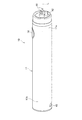
エアロゾル生成装置1は、香味成分が付加されたエアロゾルを、燃焼を伴わずに生成して、吸引可能とするための器具であり、図1及び図2に示すように、所定方向(以下、長手方向Xと呼ぶ)に沿って延びる棒形状となっている。エアロゾル生成装置1は、長手方向Xに沿って、電源ユニット10と、第1カートリッジ20と、第2カートリッジ30と、がこの順に設けられている。第1カートリッジ20は、電源ユニット10に対して着脱可能(換言すると、交換可能)である。第2カートリッジ30は、第1カートリッジ20に対して着脱可能(換言すると、交換可能)である。図3に示すように、第1カートリッジ20には、第一負荷21が設けられている。エアロゾル生成装置1の全体形状は、図1のように、電源ユニット10と、第1カートリッジ20と、第2カートリッジ30と、が一列に並ぶ形状には限らない。電源ユニット10に対して、第1カートリッジ20及び第2カートリッジ30が交換可能に構成されていれば、略箱状等の任意の形状を採用可能である。
(Aerosol generator)
The
(電源ユニット)
電源ユニット10は、図3、図4、及び図5に示すように、円筒状の電源ユニットケース11の内部に、電源12と、充電IC55Aと、MCU(Micro Controller Unit)50と、吸気センサ15と、第1通知部45及び第2通知部46を収容する。
(Power supply unit)
As shown in FIGS. 3, 4, and 5, the
電源12は、充電可能な二次電池、電気二重層キャパシタ等であり、好ましくは、リチウムイオン二次電池である。電源12の電解質は、ゲル状の電解質、電解液、固体電解質、イオン液体の1つ又はこれらの組合せで構成されていてもよい。
The
図5に示すように、MCU50は、吸気センサ15と、操作部14と、第1通知部45と、第2通知部46とに接続されており、エアロゾル生成装置1の各種の制御を行う。
As shown in FIG. 5, the
MCU50は、具体的にはプロセッサを主体に構成されており、プロセッサの動作に必要なRAM(Random Access Memory)及び各種情報を記憶するROM(Read Only Memory)等の記憶媒体により構成されるメモリ50aを更に含む。本明細書におけるプロセッサとは、具体的には、半導体素子等の回路素子を組み合わせた電気回路である。
Specifically, the
図4に示すように、電源ユニットケース11の長手方向Xの一端側(第1カートリッジ20側)に位置するトップ部11aには、放電端子41が設けられる。放電端子41は、トップ部11aの上面から第1カートリッジ20に向かって突出するように設けられ、第1カートリッジ20の第一負荷21と電気的に接続可能に構成される。
As shown in FIG. 4, a
また、トップ部11aの上面には、放電端子41の近傍に、第1カートリッジ20の第一負荷21に空気を供給する空気供給部42が設けられている。
Further, on the upper surface of the
電源ユニットケース11の長手方向Xの他端側(第1カートリッジ20と反対側)に位置するボトム部11bには、外部電源(図示省略)と電気的に接続可能な充電端子43が設けられる。充電端子43は、ボトム部11bの側面に設けられ、例えば、USB(Universal Serial Bus)端子、又はmicroUSB端子等が接続可能である。
A
なお、充電端子43は、外部電源から送電される電力を非接触で受電可能な受電部であってもよい。このような場合、充電端子43(受電部)は、受電コイルから構成されていてもよい。非接触による電力伝送(Wireless Power Transfer)の方式は、電磁誘導型でもよいし、磁気共鳴型でもよいし、電磁誘導型と磁気共鳴型を組合せたものでもよい。また、充電端子43は、外部電源から送電される電力を無接点で受電可能な受電部であってもよい。別の一例として、充電端子43は、USB端子、又はmicroUSB端子が接続可能であり、且つ上述した受電部を有していてもよい。
The
電源ユニットケース11には、ユーザが操作可能な操作部14が、トップ部11aの側面に充電端子43とは反対側を向くように設けられる。操作部14は、ボタン式のスイッチ又はタッチパネル等から構成される。電源ユニット10が電源オフの状態において、操作部14による所定の起動操作が行われると、操作部14が電源ユニット10の起動指令をMCU50に出力する。MCU50は、この起動指令を取得すると、電源ユニット10を起動させる。
The power
図3に示すように、操作部14の近傍には、パフ(吸引)動作を検出する吸気センサ15が設けられている。電源ユニットケース11には、内部に外気を取り込む不図示の空気取込口が設けられている。空気取込口は、操作部14の周囲に設けられていてもよく、充電端子43の周囲に設けられていてもよい。
As shown in FIG. 3, an
吸気センサ15は、後述の吸口32を通じたユーザの吸引により生じた電源ユニット10内の圧力(内圧)変化の値を出力するよう構成されている。吸気センサ15は、例えば、空気取込口から吸口32に向けて吸引される空気の流量に応じて変化する内圧に応じた出力値(例えば、電圧値又は電流値)を出力する圧力センサである。吸気センサ15は、アナログ値を出力してもよいし、アナログ値から変換したデジタル値を出力してもよい。
The
吸気センサ15は、検出する圧力を補償するために、電源ユニット10の置かれている環境の温度(外気温)を検出する温度センサを内蔵していてもよい。吸気センサ15は、圧力センサではなく、コンデンサマイクロフォン等から構成されていてもよい。
The
MCU50は、パフ動作が行われて、吸気センサ15の出力値が出力閾値以上になると、エアロゾルの生成要求(後述するエアロゾル源22の霧化指令)がなされたと判定し、その後、吸気センサ15の出力値がこの出力閾値を下回ると、エアロゾルの生成要求が終了されたと判定する。なお、エアロゾル生成装置1においては、第一負荷21の過熱を抑制する等の目的のために、エアロゾルの生成要求がなされている期間が上限値tupper(例えば、2.4秒)に達すると、吸気センサ15の出力値にかかわらずに、エアロゾルの生成要求が終了されたと判定されるようにしている。
When the puff operation is performed and the output value of the
なお、吸気センサ15に代えて、操作部14の操作に基づいてエアロゾルの生成要求を検出するようにしてもよい。例えば、ユーザがエアロゾルの吸引を開始するために操作部14に対し所定の操作を行うと、操作部14がエアロゾルの生成要求を示す信号をMCU50に出力するように構成してもよい。
Instead of the
充電IC55Aは、充電端子43に近接して配置され、充電端子43から入力される電力の電源12への充電制御を行う。なお、充電IC55Aは、MCU50の近傍に配置されていてもよい。
The charging
(第1カートリッジ)
図3に示すように、第1カートリッジ20は、円筒状のカートリッジケース27の内部に、エアロゾル源22を貯留する貯留部を構成するリザーバ23と、エアロゾル源22を霧化してエアロゾルを発生させる霧化器を構成する第一負荷21と、リザーバ23から第一負荷21の位置へエアロゾル源22を引き込むウィック24と、エアロゾル源22が霧化されることで発生したエアロゾルの粒径を、吸引に適した大きさにするための冷却用の通路を構成するエアロゾル流路25と、第2カートリッジ30の一部を収容するエンドキャップ26と、を備える。
(1st cartridge)
As shown in FIG. 3, the
リザーバ23は、エアロゾル流路25の周囲を囲むように区画形成され、エアロゾル源22を貯留する。リザーバ23には、樹脂ウェブ又は綿等の多孔体が収容され、且つ、エアロゾル源22が多孔体に含浸されていてもよい。リザーバ23には、樹脂ウェブ又は綿上の多孔質体が収容されず、エアロゾル源22のみが貯留されていてもよい。エアロゾル源22は、グリセリン又はプロピレングリコール等の水以外の液体と、水と、を含む。エアロゾル源22において水分が占める割合は、例えばエアロゾル源22の10%以下と十分に少ない。
The
ウィック24は、リザーバ23から毛管現象を利用してエアロゾル源22を第一負荷21の位置へ引き込む液保持部材である。ウィック24は、リザーバ23から供給されるエアロゾル源22を第一負荷21が霧化可能な位置で保持する保持部を構成している。ウィック24は、例えば、ガラス繊維や多孔質セラミックなどによって構成される。
The
第一負荷21は、電源12から放電端子41を介して供給される電力によって、燃焼を伴わずにエアロゾル源22を加熱することで、エアロゾル源22を霧化する。原則として、第一負荷21に電源12から供給される電力が多いほど、霧化されるエアロゾル源の量は多くなる。第一負荷21は、所定ピッチで巻き回される電熱線(コイル)によって構成されている。
The
なお、第一負荷21は、エアロゾル源22を加熱することで、これを霧化してエアロゾルを生成可能な素子であればよい。第一負荷21は、例えば、発熱素子である。発熱素子としては、発熱抵抗体、セラミックヒータ、及び誘導加熱式のヒータ等が挙げられる。
The
第一負荷21は、温度と電気抵抗値が相関を持つものが用いられる。第一負荷21としては、例えば、温度の増加に伴って電気抵抗値も増加するPTC(Positive Temperature Coefficient)特性を有するものが用いられる。第一負荷21としては、例えば、温度の増加に伴って電気抵抗値が減少するNTC(Negative Temperature Coefficient)特性を有するものを用いてもよい。
As the
エアロゾル流路25は、第一負荷21の下流側であって、電源ユニット10の中心線L上に設けられる。エンドキャップ26は、第2カートリッジ30の一部を収容するカートリッジ収容部26aと、エアロゾル流路25とカートリッジ収容部26aとを連通させる連通路26bと、を備える。
The
(第2カートリッジ)
第2カートリッジ30は、香味源33を貯留する。第2カートリッジ30は、第1カートリッジ20のエンドキャップ26に設けられたカートリッジ収容部26aに着脱可能に収容される。第2カートリッジ30は、第1カートリッジ20側とは反対側の端部が、ユーザの吸口32となっている。なお、吸口32は、第2カートリッジ30と一体不可分に構成される場合に限らず、第2カートリッジ30と着脱可能に構成されてもよい。このように吸口32を電源ユニット10と第1カートリッジ20とは別体に構成することで、吸口32を衛生的に保つことができる。
(2nd cartridge)
The
第2カートリッジ30は、第一負荷21によってエアロゾル源22が霧化されることで発生したエアロゾルを香味源33に通すことによってエアロゾルに香味成分を付加する。香味源33を構成する原料片としては、刻みたばこ、又は、たばこ原料を粒状に成形した成形体を用いることができる。香味源33は、たばこ以外の植物(例えば、ミント、漢方、又はハーブ等)によって構成されてもよい。香味源33には、メントール等の香料が付加されていてもよい。
The
エアロゾル生成装置1では、エアロゾル源22と香味源33によって、香味成分が付加されたエアロゾルを発生させることができる。つまり、エアロゾル源22と香味源33は、エアロゾルを発生させるエアロゾル生成源を構成している。
In the
エアロゾル生成装置1におけるエアロゾル生成源は、ユーザが交換して使用する部分である。この部分は、例えば、1つの第1カートリッジ20と、1つ又は複数(例えば5つ)の第2カートリッジ30とが1セットとしてユーザに提供される。なお、第1カートリッジ20と第2カートリッジ30を一体化して1つのカートリッジとして構成してもよい。
The aerosol generation source in the
このように構成されたエアロゾル生成装置1では、図3中の矢印Bで示すように、電源ユニットケース11に設けられた不図示の空気取込口から流入した空気が、空気供給部42から第1カートリッジ20の第一負荷21付近を通過する。第一負荷21は、ウィック24によってリザーバ23から引き込まれたエアロゾル源22を霧化する。霧化されて発生したエアロゾルは、取込口から流入した空気と共にエアロゾル流路25を流れ、連通路26bを介して第2カートリッジ30に供給される。第2カートリッジ30に供給されたエアロゾルは、香味源33を通過することで香味成分が付加され、吸口32に供給される。
In the
また、エアロゾル生成装置1には、ユーザに対して各種情報を通知する第1通知部45と第2通知部46が設けられている(図5参照)。第1通知部45は、ユーザの触覚に作用する通知を行うためのものであり、バイブレーター等の振動素子によって構成されている。第2通知部46は、ユーザの視覚に作用する通知を行うためのものであり、LED(Light Emitting Diode)等の発光素子によって構成される。各種情報を通知する通知部として、更に、ユーザの聴覚に作用する通知を行うため音出力素子が設けられてもよい。第1通知部45と第2通知部46は、電源ユニット10、第1カートリッジ20、及び第2カートリッジ30のいずれに設けられてもよいが、電源ユニット10に設けられることが好ましい。例えば、操作部14の周囲が透光性を有し、LED等の発光素子によって発光するように構成される。
Further, the
(電源ユニットの詳細)
図5は、第1カートリッジ20が装着された状態の電源ユニット10の内部の電気的な詳細構成例を示す図である。図5に示すように、電源ユニット10は、電源12と、MCU50と、LDO(Low Drop Out)レギュレータ60と、DC/DCコンバータ51と、開閉器SW1と、開閉器SW3と、オペアンプOP1と、アナログデジタル変換器(以下、ADCと記載)50bと、抵抗素子Rsと、を備える。
(Details of power supply unit)
FIG. 5 is a diagram showing a detailed electrical configuration example inside the
本明細書にて説明する抵抗素子とは、固定の電気抵抗値を持つ素子であればよく、例えば抵抗器、ダイオード、又はトランジスタ等である。図5の例では、抵抗素子Rsが抵抗器となっている。 The resistance element described in the present specification may be an element having a fixed electric resistance value, for example, a resistor, a diode, a transistor, or the like. In the example of FIG. 5, the resistance element Rs is a resistor.
本明細書にて説明する開閉器とは、配線路の遮断と導通を切り替えるトランジスタ等のスイッチング素子である。図5の例では、開閉器SW1及び開閉器SW3は、それぞれトランジスタとなっている。 The switch described in the present specification is a switching element such as a transistor that switches between blocking and conducting a wiring path. In the example of FIG. 5, the switch SW1 and the switch SW3 are transistors, respectively.
LDOレギュレータ60は、電源12の正極に接続された主正母線LUに接続されている。MCU50は、LDOレギュレータ60と、電源12の負極に接続された主負母線LDとに接続されている。MCU50は、開閉器SW1及び開閉器SW3の各々にも接続されており、これらの制御を行う。LDOレギュレータ60は、電源12からの電圧を降圧して出力する。LDOレギュレータ60の出力電圧V1は、MCU50、DC/DCコンバータ51及びオペアンプOP1の各々の動作電圧としても利用される。
The
DC/DCコンバータ51は、主正母線LUに接続されている。第一負荷21は、主負母線LDに接続される。開閉器SW1は、DC/DCコンバータ51と第一負荷21の間に接続されている。以下では、第一負荷21の電気抵抗値をR1と記載する。
The DC /
オペアンプOP1の反転入力端子は、オペアンプOP1の出力端子及び主負母線LDの各々に抵抗素子を介して接続されている。オペアンプOP1の非反転入力端子は、開閉器SW1と第一負荷21の接続ノードN1に接続されている。オペアンプOP1の正電源端子は、LDOレギュレータ60の出力電圧V1を供給する電源線に接続されている。オペアンプOP1の負電源端子は、主負母線LDに接続されている。したがって、オペアンプOP1が増幅することのできる差動入力電圧の範囲は、0Vから出力電圧V1までの範囲となる。
The inverting input terminal of the operational amplifier OP1 is connected to each of the output terminal of the operational amplifier OP1 and the main negative bus LD via a resistance element. The non-inverting input terminal of the operational amplifier OP1 is connected to the switch SW1 and the connection node N1 of the
ADC50bは、オペアンプOP1の出力端子と接続されている。ADC50bは、MCU50の外部に設けられていてもよい。
The
抵抗素子Rsは、オペアンプOP1の非反転入力端子に接続されている。抵抗素子RsとオペアンプOP1の非反転入力端子との接続ノードN3は、接続ノードN1に接続されている。以下では、抵抗素子Rsの電気抵抗値をR3と記載する。 The resistance element Rs is connected to the non-inverting input terminal of the operational amplifier OP1. The connection node N3 between the resistance element Rs and the non-inverting input terminal of the operational amplifier OP1 is connected to the connection node N1. Hereinafter, the electric resistance value of the resistance element Rs is referred to as R3.
開閉器SW3は、LDOレギュレータ60の出力電圧V1を供給する電源線と、抵抗素子Rsとの間に接続されている。
The switch SW3 is connected between the power supply line that supplies the output voltage V1 of the
MCU50のプロセッサは、第一負荷21の温度を取得できるように構成される。第一負荷21の温度は、第一負荷21又はエアロゾル源22の過熱の抑制や、第一負荷21が霧化するエアロゾル源22の量を高度に制御するために用いることができる。
The processor of the
(MCU)
次に、MCU50の機能について説明する。MCU50は、ROMに記憶されたプログラムをプロセッサが実行することにより実現される機能ブロックとして、温度検出部と、電力制御部と、通知制御部と、を備える。
(MCU)
Next, the function of the
温度検出部は、ADC50bの出力に基づいて、第一負荷21の温度を取得する。
The temperature detection unit acquires the temperature of the
温度検出部は、第一負荷21の電気抵抗値R1を検出するために電源12から第一負荷21及び抵抗素子Rsの直列回路へ放電させる第二放電制御を行う。第二放電制御では、温度検出部は、開閉器SW1を遮断状態に制御し、開閉器SW3を導通状態に制御した第一状態を形成する。この第一状態は、出力電圧V1を供給する電源線と主負母線LDの間を、抵抗素子Rsと第一負荷21の直列回路にて接続した状態である。温度検出部は、この第一状態にて、ADC50bの出力値(第一負荷21に印加される電圧値)を取得し、この出力値に基づいて第一負荷21の温度を取得する。この出力値は、具体的には、{R1/(R3+R1)}×V1で表されるオペアンプOP1の差動入力電圧を、オペアンプOP1にて所定の増幅率にて増幅した値に相当する。前述したように、第一負荷21は、温度と電気抵抗値が相関を持つ特定を持つため、第一状態におけるADC50bの出力値に基づいて、第一負荷21の電気抵抗値を導出でき、この電気抵抗値から第一負荷21の温度を取得できる。
The temperature detection unit performs a second discharge control of discharging the electric resistance value R1 of the
通知制御部は、各種情報を通知するように第1通知部45と第2通知部46を制御する。例えば、通知制御部は、第2カートリッジ30の交換タイミングの検出に応じて、第2カートリッジ30の交換を促す通知を行うように第1通知部45と第2通知部46の少なくとも一方を制御する。通知制御部は、第2カートリッジ30の交換を促す通知に限らず、第1カートリッジ20の交換を促す通知、電源12の交換を促す通知、電源12の充電を促す通知等を行わせてもよい。
The notification control unit controls the
電力制御部は、吸気センサ15から出力されたエアロゾルの生成要求を示す信号に応じて、エアロゾルを生成するために電源12から第一負荷21へ放電させる第一放電制御を行う。第一放電制御では、電力制御部は、開閉器SW1を導通状態且つ開閉器SW3を遮断状態とする第二状態を形成し、DC/DCコンバータ51から第一負荷21へと電力を供給させる。第一負荷21の温度は、第一放電制御が行われる状態においては、常温(日本工業規格で定められた常温)から例えば200℃程度の高温まで上昇する。
The power control unit performs first discharge control for discharging the aerosol from the
電源ユニット10では、第一負荷21の温度がエアロゾル生成時の温度よりも十分に低い状態(例えば、常温の状態)において、抵抗素子Rsと第一負荷21の直列回路への放電を行った場合に、第一負荷21の温度が、30℃以上100℃未満の範囲となるように、抵抗素子Rsの電気抵抗値R3と、直列回路に供給される電圧(出力電圧V1)とが決められている。一例として、抵抗素子Rsの電気抵抗値R3は、10Ω程度と比較的小さい値となっている。
In the
第一負荷21の温度検出時には、第一負荷21に多くの電力が供給されると、第一負荷21が加熱されてしまう。そのため、温度検出時には、直列回路の抵抗素子Rsの電気抵抗値R3を100Ω等といった十分に大きい値にするのが一般的である。これに対し、本実施形態の電源ユニット10では、抵抗素子Rsの電気抵抗値R3を10Ω程度と小さくすることで、第一負荷21が常温の状態において第二放電制御を行った際に、第一負荷21の温度が多少上昇するようにしている。電源12として一般的なリチウムイオン電池を用いることを想定すると、電気抵抗値R3は、常温における第一負荷21の電気抵抗値R1の1倍以上30倍未満、好ましくは5倍以上20倍未満とすることで、第一負荷21が常温の状態にて第二放電制御を行った場合に、第一負荷21の温度を30℃以上100℃未満の範囲にすることが容易となる。なお、このように電気抵抗値R3を小さい値にすると、第一負荷21の温度検出分解能を高めることができる。
When the temperature of the
MCU50は、上記の第一放電制御及び上記の第二放電制御を行う期間以外の特定の期間において、電源12から上記の直列回路へ放電させる第三放電制御を行う。この第三放電制御は、第二放電制御と同じものであるが、その目的が異なる。
The
第三放電制御は、第一負荷21近傍に存在する水分を蒸発させるために行われる。第一負荷21近傍には、第一負荷21に吸収された水分、ウィック24に引き込まれたエアロゾル源22に含まれる水分、及び第一負荷21の設けられた空間の水分等が存在する。前述したように、第二放電制御と同じ内容の第三放電制御を行っても、第一負荷21の温度は、常温から、30℃以上100℃未満の範囲までしか変化しない。しかし、この範囲の温度であれば、ある程度の時間かけることで、第一負荷21近傍に存在する水分を蒸発させることができる。
The third discharge control is performed to evaporate the water existing in the vicinity of the
なお、第一負荷21の温度を検出するタイミング(第二放電制御を行うタイミング)は、第一放電制御が行われる期間とこの期間の終了直後等である。このようなタイミングでは、第一負荷21の温度が上記の範囲よりも十分に高い状態となっている。このため、第二放電制御を行うことによる第一負荷21の温度上昇は無視できる。
The timing for detecting the temperature of the first load 21 (timing for performing the second discharge control) is a period during which the first discharge control is performed, immediately after the end of this period, and the like. At such a timing, the temperature of the
(エアロゾル生成装置の動作)
図6は、図1のエアロゾル生成装置1の動作を説明するためのフローチャートである。
操作部14が操作されて電源ユニット10の電源がONになると(ステップS1:YES)、MCU50は、前回のエアロゾル生成からの経過時間T1を取得する(ステップS2)。MCU50は、エアロゾルの生成要求に応じて開始した第一放電制御を終了させた時点で、メモリ50aに、エアロゾルの生成終了時刻を記憶する。ステップS2において、MCU50は、このメモリ50aに記憶されたエアロゾルの生成終了時刻と、現在時刻との差分を上記の経過時間T1として取得する。
(Operation of aerosol generator)
FIG. 6 is a flowchart for explaining the operation of the
When the
また、電源ユニット10の電源がONになると、MCU50は、第三放電制御を開始する(ステップS3)。その後、第三放電制御を開始してからの経過時間が、ステップS2にて取得した経過時間T1に応じた時間T2に達すると(ステップS4:YES)、MCU50は第三放電制御を終了する(ステップS5)。時間T2は、経過時間T1が長いほど、大きい値が設定される。
Further, when the power supply of the
ステップS5の後、MCU50は、エアロゾルの生成要求が開始されると(ステップS6:YES)、第一放電制御を開始する(ステップS7)。その後、エアロゾルの生成要求が終了されると(ステップS8:YES)、MCU50は、第一放電制御を終了し(ステップS9)、メモリ50aに、エアロゾルの生成終了時刻を記憶する。
After step S5, the
MCU50は、ステップS7からステップS9の間において、例えば、第一放電制御と第二放電制御を交互に繰り返し行う。これにより、第一負荷21を加熱しながら、第一負荷21の温度を検出して、第一負荷21の過熱の抑制や、第一負荷21へ放電する電力の制御によるエアロゾル生成量の調整等を行う。MCU50は、ステップS7からステップS9の期間以外の期間では、第一放電制御と第二放電制御を行わないことが望ましい。
The
MCU50は、ステップS9の後、エアロゾル生成装置1の電源がOFFされれば処理を終了し、電源がOFFされなければ、ステップS6に処理を戻す。
After step S9, the
以上のように、エアロゾル生成装置1によれば、エアロゾル生成と第一負荷21の電気抵抗値R1の検出とを行わない特定の期間(具体的には、電源ユニット10の起動後、最初のエアロゾル生成(第一放電制御)が開始されるまでの期間)において、第三放電制御が行われる。このため、この第三放電制御によって、第一負荷21を僅かに加熱して、第一負荷21近傍に存在する水分を蒸発させることが可能になる。第一負荷21近傍の水分が蒸発することで、後の第一放電制御を行った場合に生成されるエアロゾルに多くの水分が含まれるのを防いで、香喫味の低下を抑制できる。また、電源ユニット10の起動後、最初のエアロゾルの生成が開始されるまでの間に水分を蒸発させることができる。このため、電源投入後の最初の吸引から十分な香喫味をユーザに提供できる。
As described above, according to the
また、エアロゾル生成装置1では、ステップS3からステップS5の期間における第一負荷21の温度は、30℃以上100℃未満の範囲となり、第一放電制御が行われているときと比べて高温にならない。このため、ユーザに意識させることなく、第一負荷21近傍の水分を蒸発させることができる。また、吸引を行っていないときの電源ユニット10の温度上昇を防いで、ユーザに安心感を与えることができる。
Further, in the
また、エアロゾル生成装置1によれば、電源ユニット10の電源オン後、ユーザが吸引の準備を行っている間に、第一負荷21近傍の水分を蒸発させることができる。このため、ユーザに意識させることなく、第一負荷21近傍の水分を蒸発させることができる。
Further, according to the
電源ユニット10が起動していない状態では、エアロゾル生成装置1がある程度の時間放置されていると考えられる。つまり、この状態では、エアロゾル生成装置1外部の湿気や、吸口32から侵入したユーザの唾液等によって、第一負荷21近傍の水分量が増加している可能性が高い。このため、電源ユニット10の起動後に第一負荷21近傍の水分を蒸発させることが特に有効となる。
It is considered that the
なお、ステップS3からステップS5の期間の第三放電制御において蒸発しきらない水分があったとしても、後の第一放電制御において、この水分は蒸発される。そのため、電源ユニット10の起動後、2回目以降のエアロゾル生成の際には、第一負荷21近傍にはほとんど水分が存在しない状況となる。したがって、電源ユニット10の起動後、最初のエアロゾル生成が終了してからは、第三放電制御を行わないようにすることで、吸引を行っていないときの電力消費を抑制できる。
Even if there is water that cannot be completely evaporated in the third discharge control during the period from step S3 to step S5, this water is evaporated in the subsequent first discharge control. Therefore, after the
また、エアロゾル生成装置1によれば、前回のエアロゾルの生成終了時点から第三放電制御の開始時点までの経過時間T1に基づいて、第三放電制御を行う時間が制御される。経過時間T1は、その値が大きいほど、第一負荷21近傍の水分量が多くなっている可能性が高いことを意味する。このように、第一負荷21近傍の水分量と高い相関を有する経過時間T1に基づいて第三放電制御を行う時間を決めることで、第一負荷21近傍の水分量に応じた適切な放電が可能になり、電力を効率よく利用できる。
Further, according to the
なお、図6のステップS3からステップS5までの時間は、経過時間T1に基づく値(=時間T2)としているが、これに限らず、実験的に決めた固定値(一例として、10秒から15秒等)とすることも可能である。時間T2の取り得る範囲は、一例として、10秒から15秒とすればよいが、これに限られるものではない。 The time from step S3 to step S5 in FIG. 6 is a value based on the elapsed time T1 (= time T2), but is not limited to this, and is an experimentally determined fixed value (for example, 10 seconds to 15). Seconds, etc.) are also possible. The possible range of the time T2 may be, for example, 10 to 15 seconds, but is not limited to this.
(エアロゾル生成装置の動作の第一変形例)
図7は、図1のエアロゾル生成装置1の動作の第一変形例を説明するためのフローチャートである。図7に示すフローチャートは、ステップS2が削除された点と、ステップS4がステップS4a、ステップS4b、及びステップS4cに変更された点と、を除いては、図6と同じである。以下、変更点を中心に説明する。
(First modification of the operation of the aerosol generator)
FIG. 7 is a flowchart for explaining a first modification of the operation of the
電源ユニット10の電源がONになると(ステップS1:YES)、MCU50は、第三放電制御を開始する(ステップS3)。その後、MCU50は、ADC50bの出力に基づいて、第一負荷21の電気抵抗値を単位時間経過毎に取得し、この電気抵抗値の単位時間における変動量(絶対値)を求める(ステップS4a)。そして、MCU50は、第一負荷21の電気抵抗値の変動量が閾値TH1以上か否かを判定する(ステップS4b)。
When the power supply of the
MCU50は、変動量が閾値TH1未満であった場合(ステップS4b:NO)には、第三放電制御を開始してからの経過時間が予め決められた上限時間に達したか否かを判定する(ステップS4c)。MCU50は、第三放電制御を開始してからの経過時間が上限時間に達していない場合(ステップS4c:NO)には、ステップS4aに処理を戻す。
When the fluctuation amount is less than the threshold value TH1 (step S4b: NO), the
MCU50は、第三放電制御を開始してからの経過時間が上限時間に達した場合(ステップS4c:YES)には、ステップS5において第三放電制御を終了する。MCU50は、変動量が閾値TH1以上となった場合(ステップS4b:YES)にも、ステップS5において第三放電制御を終了する。
When the elapsed time from the start of the third discharge control reaches the upper limit time (step S4c: YES), the
第三放電制御が行われて第一負荷21の温度が上昇し、第一負荷21近傍の水分が蒸発すると、この蒸発に伴う気化熱によって第一負荷21の温度が低下する。したがって、第一負荷21の電気抵抗値は、水分の蒸発前後で大きく変動する。このため、図7の動作のように、第一負荷21の電気抵抗値の変動量が閾値TH1以上となるタイミング(換言すると、水分が蒸発されたタイミング)で第三放電制御を終了させることで、水分がない状態で放電が継続されるのを防いで、電力消費を抑制できる。
When the third discharge control is performed to raise the temperature of the
(エアロゾル生成装置の動作の第二変形例)
図8は、図1のエアロゾル生成装置1の動作の第二変形例を説明するためのフローチャートである。図8に示すフローチャートは、ステップS2からステップS5が削除された点と、ステップS11からステップS15が追加された点と、を除いては、図6と同じである。以下、変更点を中心に説明する。
(Second modification of the operation of the aerosol generator)
FIG. 8 is a flowchart for explaining a second modification of the operation of the
電源ユニット10の電源がONになると(ステップS1:YES)、MCU50は、エアロゾルの生成要求が開始されたか否かを判定する(ステップS6)。エアロゾルの生成要求が開始された場合(ステップS6:YES)には、ステップS7以降の処理が行われる。
When the power supply of the
エアロゾルの生成要求が開始されていない場合(ステップS6:NO)には、MCU50は、電源ユニット10の周囲の湿度の情報を取得する(ステップS11)。湿度の情報の取得方法は、任意であるが、例えば次の第一取得方法、第二取得方法、第三取得方法を採用できる。
When the aerosol generation request has not been started (step S6: NO), the
第一取得方法は、電源ユニット10の内部に湿度センサを設けて、この湿度センサの検出情報を取得する方法である。第二取得方法は、電源ユニット10の内部に、湿度情報を提供するサービスサーバに接続された外部機器(例えばユーザのスマートフォン)と通信可能なインタフェースを設けておき、この外部機器を介して、サービスサーバからエアロゾル生成装置1の存在場所における湿度の情報を取得する方法である。第三取得方法は、電源ユニット10の内部に気圧センサを設け、この気圧センサの検出情報と、電源ユニット10の内部に設けられた温度センサの検出情報から、湿度を推定する方法である。
The first acquisition method is a method in which a humidity sensor is provided inside the
MCU50は、ステップS11で湿度の情報を取得した後、取得した湿度が閾値TH2を超えるか否かを判定する(ステップS12)。MCU50は、湿度が閾値TH2以下であった場合(ステップS12:NO)には、ステップS6に処理を戻す。
After acquiring the humidity information in step S11, the
MCU50は、湿度が閾値TH2を超えていた場合(ステップS12:YES)には、第三放電制御を開始する(ステップS13)。MCU50は、第三放電制御の開始後、所定時間(一例として、10秒から15秒等)が経過すると(ステップS14:YES)、第三放電制御を終了する(ステップS15)。ステップS15の後はステップS6に処理が移行される。
When the humidity exceeds the threshold value TH2 (step S12: YES), the
以上の第二変形例の動作によれば、電源ユニット10の周囲の湿度が高く、第一負荷21近傍に水分が多く存在していると想定される場合にのみ、ステップS13にて第三放電制御が開始される。このように、必要なときだけ第三放電制御を行うことで、図6及び図7の動作と比較して、電力消費を抑制できる。
According to the operation of the second modification described above, the third discharge in step S13 is performed only when the humidity around the
なお、図8の動作において、ステップS13で開始した第三放電制御を終了させるタイミングは、図7で説明したように、第一負荷21の電気抵抗値の変動量が閾値TH1以上となった時点と、第三放電制御の開始から所定時間が経過した時点とのどちらか早い方としてもよい。また、第一負荷21近傍の湿度を取得し、この湿度が低くなった時点で第三放電制御を終了させてもよい。
In the operation of FIG. 8, the timing of ending the third discharge control started in step S13 is when the fluctuation amount of the electric resistance value of the
(エアロゾル生成装置の動作の第三変形例)
ここまでのエアロゾル生成装置1の動作の説明では、電源ユニット10の電源がONの状態で、第三放電制御を行うものとした。しかし、第三放電制御は、外部電源(モバイルバッテリやコンセント等)からの電力が電源12に供給可能な状態において、実行するようにしてもよい。外部電源からの電力が電源12に供給可能な状態とは、充電端子43と外部電源が電気的に接続された状態であり、換言すると、電源12の充電が可能となっている状態である。
(Third variant of the operation of the aerosol generator)
In the description of the operation of the
図9は、図1のエアロゾル生成装置1の動作の第三変形例を説明するためのフローチャートである。MCU50は、電源ユニット10の充電端子43が外部電源に接続されているか否かを判定する(ステップS21)。充電端子43が外部電源に接続されている状態とは、充電端子43に外部電源から電力が供給可能になっている状態を言う。
FIG. 9 is a flowchart for explaining a third modification of the operation of the
MCU50は、充電端子43が外部電源に接続されている場合(ステップS21:YES)には、外部電源から供給される電力によって電源12の充電を開始する(ステップS22)。充電を開始すると、MCU50は、内蔵するタイマを初期値(=0)にリセットして、計時を開始する(ステップS23)。
When the charging
MCU50は、タイマの計時値が所定値Txとなっているか判定し(ステップS24)、計時値が所定値Txとなっていた場合(ステップS24:YES)に、第三放電制御を開始する(ステップS25)。
The
MCU50は、第三放電制御を開始してから所定時間(一例として、10秒から15秒等)が経過すると(ステップS26:YES)、第三放電制御を終了する(ステップS27)。ステップS27の後は、ステップS23に処理が移行される。このように、電源12の充電期間では、所定値Txの時間が経過する毎に、第三放電制御が行われる。所定値Txは、水分が第一負荷21近傍に吸着され得る程度に長い時間とするのが好ましく、例えば1時間、2時間、4時間、8時間といった任意の値が設定される。
The
以上の第三変形例の動作によれば、ユーザがエアロゾル生成装置1を利用していない期間である電源12の充電期間に、第一負荷21近傍の水分を蒸発させることができる。このため、ユーザに意識させることなく、第一負荷21近傍の水分を蒸発させることができる。また、電源12の充電はある程度の時間をかけて行われるため、第一負荷21近傍の水分量が増加しやすい。このような水分量が増加しやすい期間において定期的に第三放電制御が行われることで、第一負荷21近傍の水分を効果的に除去することができる。
According to the operation of the third modification as described above, the water in the vicinity of the
なお、図9の動作において、ステップS25で開始した第三放電制御を終了させるタイミングは、図7で説明したように、第一負荷21の電気抵抗値の変動量が閾値TH1以上となった時点と、第三放電制御の開始から所定時間が経過した時点とのどちらか早い方としてもよい。または、図8で説明したように、第一負荷21近傍の湿度が閾値TH2以下となったタイミングで第三放電制御を終了させてもよい。また、図9のステップS24〜27の処理は、電源ユニット10の周囲の湿度が閾値TH2を超えているときのみ行ってもよい。
In the operation of FIG. 9, the timing of ending the third discharge control started in step S25 is when the fluctuation amount of the electric resistance value of the
また、上記の所定値Txを、電源ユニット10の周囲の湿度に応じて可変制御してもよい。例えば、湿度が高いときは、湿度が低いときと比べて所定値Txを小さくする。このようにすることで、湿度が高く、第一負荷21近傍に水分が集まりやすい状況においては、第三放電制御を高頻度にて実行することができ、この水分を効果的に除去できる。また、所定値Txは、電源12の充電が行われている期間においては相対的に小さい値とし、電源12の充電が完了した後の期間においては相対的に大きい値としてもよい。こうすることで、電源12の充電完了までの時間を短縮できる。
Further, the above-mentioned predetermined value Tx may be variably controlled according to the humidity around the
また、充電端子43と外部電源が接続された状態において、電源12の充電が行われている間は第三放電制御を行わず、電源12の充電が完了した後の放置期間においてのみ第三放電制御を行うようにしてもよい。このようにすることで、充電を早期に完了させることができる。また、充電完了後の放置期間において、第一負荷21近傍の水分を蒸発させることができる。なお、電源ユニット10では、充電端子43と外部電源が接続された状態においては、第一放電制御と第二放電制御は行わないことが望ましい。
Further, in the state where the charging
ここまでの説明では、MCU50が、エアロゾル生成と第一負荷21の電気抵抗値R1の検出とを行わない特定の期間において、第三放電制御を行うことで、第一負荷21近傍に存在する水分を蒸発させることを可能とした。この変形例として、MCU50が、エアロゾル生成と第一負荷21の電気抵抗値R1の検出とを行わない特定の期間において、第四放電制御を行うことで、第一負荷21近傍に存在する水分を蒸発させてもよい。
第四放電制御は、図5において、開閉器SW3を遮断状態に制御し、開閉器SW1を導通状態に制御するものであり、第一放電制御の制御内容と酷似している。第一放電制御と第四放電制御の違いは、第四放電制御の継続される時間が、第一放電制御の継続される時間よりも十分に短い点にある。具体的には、第四放電制御は、第一負荷21の温度が水分の蒸発に必要な100℃程度に達するのに必要な時間だけ実行される。このように、第四放電制御によって抵抗素子Rsを介さずに第一負荷21に僅かな時間だけ放電して、第一負荷21近傍の水分を蒸発させることでも、後の第一放電制御を行った場合に生成されるエアロゾルに多くの水分が含まれるのを防いで、香喫味の低下を抑制できる。
In the description so far, the moisture existing in the vicinity of the
In FIG. 5, the fourth discharge control controls the switch SW3 to the cutoff state and the switch SW1 to the conductive state, which is very similar to the control content of the first discharge control. The difference between the first discharge control and the fourth discharge control is that the duration of the fourth discharge control is sufficiently shorter than the duration of the first discharge control. Specifically, the fourth discharge control is executed only for the time required for the temperature of the
本明細書には少なくとも以下の事項が記載されている。なお、括弧内には、上記した実施形態において対応する構成要素等を示しているが、これに限定されるものではない。 At least the following matters are described in this specification. The components and the like corresponding to the above-described embodiments are shown in parentheses, but the present invention is not limited thereto.
(1)
エアロゾル源(エアロゾル源22)を加熱する第一負荷(第一負荷21)に放電可能な電源(電源12)と、
上記第一負荷に直列接続可能に構成された上記第一負荷の電気抵抗値を検出するための抵抗素子(抵抗素子Rs)と、
処理装置(MCU50のプロセッサ)と、を備え、
上記処理装置は、
エアロゾルを生成するために上記電源から上記第一負荷へ放電させる第一放電制御と、上記第一負荷の電気抵抗値を検出するために上記電源から上記第一負荷及び上記抵抗素子の直列回路へ放電させる第二放電制御と、を行い、
上記第一放電制御及び上記第二放電制御を行う期間以外の特定の期間において、上記電源から上記直列回路へ放電させる第三放電制御を行うエアロゾル生成装置の電源ユニット。
(1)
A power supply (power supply 12) capable of discharging to the first load (first load 21) that heats the aerosol source (aerosol source 22), and
A resistance element (resistance element Rs) for detecting the electric resistance value of the first load configured to be connected in series to the first load, and
It is equipped with a processing device (processor of MCU50).
The above processing device
The first discharge control that discharges from the power supply to the first load to generate an aerosol, and the series circuit of the first load and the resistance element from the power supply to detect the electric resistance value of the first load. Perform the second discharge control to discharge,
A power supply unit of an aerosol generator that performs a third discharge control for discharging from the power source to the series circuit in a specific period other than the period in which the first discharge control and the second discharge control are performed.
(1)によれば、エアロゾル生成と第一負荷の電気抵抗値の検出とを行わない特定の期間において、第一負荷と抵抗素子の直列回路への放電が行われる。このため、この放電によって、第一負荷を加熱して、第一負荷近傍に存在する水分を蒸発させることが可能になる。第一負荷近傍の水分が蒸発することで、第一放電制御を行った場合に生成されるエアロゾルに水分が含まれるのを防いで、香喫味の低下を抑制できる。 According to (1), the discharge of the first load and the resistance element to the series circuit is performed in a specific period during which the aerosol generation and the detection of the electric resistance value of the first load are not performed. Therefore, this discharge makes it possible to heat the first load and evaporate the water existing in the vicinity of the first load. By evaporating the water content in the vicinity of the first load, it is possible to prevent the aerosol generated when the first discharge control is performed from containing the water content and suppress the deterioration of the flavor and taste.
(2)
(1)記載のエアロゾル生成装置の電源ユニットであって、
上記第三放電制御が行われている状態における上記第一負荷の温度が、30℃以上100℃未満の範囲となるように、上記抵抗素子の電気抵抗値と上記第三放電制御において上記直列回路に供給される電圧とが決められているエアロゾル生成装置の電源ユニット。
(2)
(1) The power supply unit of the aerosol generator described above.
The electric resistance value of the resistance element and the series circuit in the third discharge control so that the temperature of the first load in the state where the third discharge control is performed is in the range of 30 ° C. or higher and lower than 100 ° C. The power supply unit of the aerosol generator whose voltage is determined to be supplied to.
(2)によれば、第三放電制御が行われている状態にて第一負荷の温度が高温にならないため、ユーザに意識させることなく、第一負荷近傍の水分を蒸発させることができる。また、吸引を行っていないときの電源ユニットの温度上昇を防いで、ユーザに安心感を与えることができる。 According to (2), since the temperature of the first load does not become high in the state where the third discharge control is performed, the water in the vicinity of the first load can be evaporated without making the user aware of it. In addition, it is possible to prevent the temperature of the power supply unit from rising when suction is not performed, which gives the user a sense of security.
(3)
(1)又は(2)記載のエアロゾル生成装置の電源ユニットであって、
上記処理装置は、外部電源からの電力が上記電源に供給可能な状態において、上記第三放電制御を行うエアロゾル生成装置の電源ユニット。
(3)
The power supply unit of the aerosol generator according to (1) or (2).
The processing device is a power supply unit of an aerosol generating device that performs the third discharge control in a state where electric power from an external power source can be supplied to the power source.
(4)
(3)記載のエアロゾル生成装置の電源ユニットであって、
上記処理装置は、上記電源の充電中に上記第三放電制御を行うエアロゾル生成装置の電源ユニット
(4)
(3) The power supply unit of the aerosol generator described above.
The processing device is a power supply unit of an aerosol generator that controls the third discharge while charging the power supply.
(3)、(4)によれば、ユーザがエアロゾル生成装置を利用していない期間である電源の充電中に水分を蒸発させることができる。このため、ユーザに意識させることなく、第一負荷近傍の水分を蒸発させることができる。また、電源の充電はある程度の時間をかけて行われるため、第一負荷近傍の水分量が増加しやすい。このような水分量が増加しやすい期間において第三放電制御が行われることで、第一負荷近傍の水分を効果的に除去することができる。 According to (3) and (4), the water can be evaporated during the charging of the power source during the period when the user is not using the aerosol generator. Therefore, it is possible to evaporate the water in the vicinity of the first load without making the user aware of it. Further, since the power supply is charged over a certain period of time, the amount of water in the vicinity of the first load tends to increase. By performing the third discharge control during such a period in which the amount of water is likely to increase, it is possible to effectively remove the water in the vicinity of the first load.
(5)
(1)又は(2)記載のエアロゾル生成装置の電源ユニットであって、
上記処理装置は、上記電源ユニットの起動後に上記第三放電制御を行うエアロゾル生成装置の電源ユニット。
(5)
The power supply unit of the aerosol generator according to (1) or (2).
The processing device is a power supply unit of an aerosol generator that performs the third discharge control after the power supply unit is started.
(5)によれば、電源オン後、ユーザが吸引の準備を行っている間に水分を蒸発させることができる。このため、ユーザに意識させることなく、第一負荷近傍の水分を蒸発させることができる。電源が起動していない状態では、電源ユニットがある程度の時間放置されていると考えられ、第一負荷近傍の水分量が増加している可能性が高い。このため、電源の起動後に水分を蒸発させることで、第一負荷近傍の水分を効果的に除去することができる。 According to (5), after the power is turned on, the water can be evaporated while the user is preparing for suction. Therefore, it is possible to evaporate the water in the vicinity of the first load without making the user aware of it. When the power supply is not started, it is considered that the power supply unit is left for a certain period of time, and it is highly possible that the amount of water in the vicinity of the first load is increasing. Therefore, by evaporating the water content after the power supply is started, the water content in the vicinity of the first load can be effectively removed.
(6)
(5)記載のエアロゾル生成装置の電源ユニットであって、
上記処理装置は、上記電源ユニットの起動後、最初の上記第一放電制御を行うまでの期間に上記第三放電制御を行うエアロゾル生成装置の電源ユニット。
(6)
(5) The power supply unit of the aerosol generator according to the above.
The processing device is a power supply unit of an aerosol generator that performs the third discharge control during the period from the start of the power supply unit to the first first discharge control.
(6)によれば、最初のエアロゾルの生成が開始されるまでの間に水分を蒸発させることができる。このため、電源投入後の最初の吸引から十分な香喫味をユーザに提供できる。 According to (6), the water can be evaporated before the production of the first aerosol is started. Therefore, it is possible to provide the user with a sufficient flavor and taste from the first suction after the power is turned on.
(7)
(5)又は(6)記載のエアロゾル生成装置の電源ユニットであって、
上記処理装置は、
前回のエアロゾルの生成終了時点から上記第三放電制御の開始時点までの経過時間(経過時間T1)に基づいて、上記第三放電制御を行う時間を制御するエアロゾル生成装置の電源ユニット。
(7)
The power supply unit of the aerosol generator according to (5) or (6).
The above processing device
A power supply unit of an aerosol generator that controls the time for performing the third discharge control based on the elapsed time (elapsed time T1) from the end of the previous aerosol generation to the start of the third discharge control.
(7)によれば、第一負荷近傍の水分量と高い相関を有する上記経過時間に基づいて第三放電制御を行う時間が決められる。このため、水分量に応じた適切な放電が可能になり、電力を効率よく利用できる。 According to (7), the time for performing the third discharge control is determined based on the elapsed time having a high correlation with the amount of water in the vicinity of the first load. Therefore, an appropriate discharge according to the amount of water becomes possible, and electric power can be used efficiently.
(8)
(1)又は(2)記載のエアロゾル生成装置の電源ユニットであって、
上記処理装置は、
上記電源ユニットの周囲の湿度を取得可能に構成され、
上記湿度が閾値(閾値TH2)を超える場合に、上記第三放電制御を行うエアロゾル生成装置の電源ユニット。
(8)
The power supply unit of the aerosol generator according to (1) or (2).
The above processing device
It is configured to be able to acquire the humidity around the above power supply unit.
A power supply unit of an aerosol generator that performs the third discharge control when the humidity exceeds a threshold value (threshold value TH2).
(8)によれば、第一負荷近傍の水分量が多いと想定される場合にのみ、第三放電制御がなされる。このため、電力消費を抑制できる。 According to (8), the third discharge control is performed only when it is assumed that the amount of water in the vicinity of the first load is large. Therefore, power consumption can be suppressed.
(9)
(1)から(6)、(8)のいずれか1つに記載のエアロゾル生成装置の電源ユニットであって、
上記処理装置は、
上記第三放電制御を行っているときの上記第一負荷の電気抵抗値の変動量に基づいて、上記第三放電制御を終了させるタイミングを制御するエアロゾル生成装置の電源ユニット。
(9)
The power supply unit of the aerosol generator according to any one of (1) to (6) and (8).
The above processing device
A power supply unit of an aerosol generator that controls the timing of ending the third discharge control based on the amount of fluctuation of the electric resistance value of the first load when the third discharge control is performed.
(9)によれば、第三放電制御を実行する時間を適切に決めることができる。第一負荷に水分が含まれる場合、第一負荷に放電されてこの水分が蒸発すると、蒸発に伴う気化熱によって第一負荷の温度が低下し、第一負荷の電気抵抗値の変動量が大きくなる。このため、この変動量が大きくなるタイミングで第三放電制御を終了させることで、水分がない状態で放電が継続されるのを防いで、電力消費を抑制できる。 According to (9), the time for executing the third discharge control can be appropriately determined. When the first load contains water, when it is discharged to the first load and this water evaporates, the temperature of the first load drops due to the heat of vaporization that accompanies the evaporation, and the amount of fluctuation in the electrical resistance value of the first load is large. Become. Therefore, by ending the third discharge control at the timing when the fluctuation amount becomes large, it is possible to prevent the discharge from being continued in the absence of water and suppress the power consumption.
(10)
(9)記載のエアロゾル生成装置の電源ユニットであって、
上記処理装置は、上記変動量が閾値(閾値TH1)を超えた場合に、上記第三放電制御を終了させるエアロゾル生成装置の電源ユニット。
(10)
(9) The power supply unit of the aerosol generator according to the above.
The processing device is a power supply unit of an aerosol generation device that terminates the third discharge control when the fluctuation amount exceeds a threshold value (threshold value TH1).
(10)によれば、変動量が大きくなるタイミングで第三放電制御を終了させるため、水分がない状態で放電が継続されるのを防いで、電力消費を抑制できる。 According to (10), since the third discharge control is terminated at the timing when the fluctuation amount becomes large, it is possible to prevent the discharge from being continued in the absence of water and suppress the power consumption.
(11)
(1)から(10)のいずれか1つに記載のエアロゾル生成装置の電源ユニットであって、
上記エアロゾル源を収容する収容体(第1カートリッジ20)が着脱自在に構成された本体部(電源ユニットケース11)を備え、
上記処理装置は、上記収容体が上記本体部に装着されている状態にて、上記第三放電制御を実行するエアロゾル生成装置の電源ユニット。
(11)
The power supply unit of the aerosol generator according to any one of (1) to (10).
A main body (power supply unit case 11) in which an accommodating body (first cartridge 20) accommodating the aerosol source is detachably configured is provided.
The processing device is a power supply unit of an aerosol generating device that executes the third discharge control while the housing is mounted on the main body.
(11)によれば、エアロゾル源の収容体に含まれる水分を蒸発させた状態で、エアロゾルの生成が可能になる。このため、所望の香喫味をユーザに提供できる。 According to (11), it is possible to generate an aerosol in a state where the water contained in the body of the aerosol source is evaporated. Therefore, the desired flavor and taste can be provided to the user.
(12)
エアロゾル源(エアロゾル源22)を加熱する第一負荷(第一負荷21)に放電可能な電源(電源12)と、
処理装置(MCU50のプロセッサ)と、を備え、
上記処理装置は、
エアロゾルを生成するために上記電源から上記第一負荷へ放電させる第一放電制御と、上記第一放電制御よりも低い電力を上記電源から上記第一負荷へ放電させる第三放電制御と、を行い、
上記第三放電制御を、外部電源からの電力が上記電源に供給可能な状態において行うエアロゾル生成装置の電源ユニット。
(12)
A power supply (power supply 12) capable of discharging to the first load (first load 21) that heats the aerosol source (aerosol source 22), and
It is equipped with a processing device (processor of MCU50).
The above processing device
The first discharge control for discharging the electric power from the power source to the first load and the third discharge control for discharging the electric power lower than the first discharge control from the power source to the first load are performed in order to generate an aerosol. ,
A power supply unit of an aerosol generator that performs the third discharge control in a state where electric power from an external power source can be supplied to the power source.
(13)
(12)記載のエアロゾル生成装置の電源ユニットであって、
上記処理装置は、上記電源の充電中に上記第三放電制御を行うエアロゾル生成装置の電源ユニット。
(13)
The power supply unit of the aerosol generator according to (12).
The processing device is a power supply unit of an aerosol generator that controls the third discharge while charging the power supply.
(12)、(13)によれば、ユーザがエアロゾル生成装置を利用していない期間である電源の充電中に、第三放電制御によって。第一負荷近傍に存在する水分を蒸発させることができる。このため、ユーザに意識させることなく、第一負荷近傍の水分を蒸発させることができる。また、電源の充電はある程度の時間をかけて行われるため、第一負荷近傍の水分量が増加しやすい。このような水分量が増加しやすい期間において第三放電制御が行われることで、第一負荷近傍の水分を効果的に除去することができる。 According to (12) and (13), by the third discharge control during the charging of the power source during the period when the user is not using the aerosol generator. Moisture existing in the vicinity of the first load can be evaporated. Therefore, it is possible to evaporate the water in the vicinity of the first load without making the user aware of it. Further, since the power supply is charged over a certain period of time, the amount of water in the vicinity of the first load tends to increase. By performing the third discharge control during such a period in which the amount of water is likely to increase, it is possible to effectively remove the water in the vicinity of the first load.
(14)
エアロゾル源(エアロゾル源22)を加熱する第一負荷(第一負荷21)に放電可能な電源(電源12)と、
上記第一負荷に直列接続可能に構成された上記第一負荷の電気抵抗値を検出するための抵抗素子(抵抗素子Rs)と、
処理装置(MCU50のプロセッサ)と、を備え、
上記処理装置は、
エアロゾルを生成するために上記電源から上記第一負荷へ放電させる第一放電制御と、上記第一負荷の電気抵抗値を検出するために上記電源から上記第一負荷及び上記抵抗素子の直列回路へ放電させる第二放電制御と、を行い、
上記第一放電制御及び上記第二放電制御を行う期間以外の特定の期間において、上記電源から上記抵抗素子を介さずに上記第一負荷へ放電させる第四放電制御を行うエアロゾル生成装置の電源ユニット。
(14)
A power supply (power supply 12) capable of discharging to the first load (first load 21) that heats the aerosol source (aerosol source 22), and
A resistance element (resistance element Rs) for detecting the electric resistance value of the first load configured to be connected in series to the first load, and
It is equipped with a processing device (processor of MCU50).
The above processing device
The first discharge control that discharges from the power supply to the first load to generate an aerosol, and the series circuit of the first load and the resistance element from the power supply to detect the electric resistance value of the first load. Perform the second discharge control to discharge,
A power supply unit of an aerosol generator that performs a fourth discharge control that discharges the power source from the power source to the first load without passing through the resistance element in a specific period other than the period in which the first discharge control and the second discharge control are performed. ..
(14)によれば、エアロゾル生成と第一負荷の電気抵抗値の検出とを行わない特定の期間において、第一負荷への放電が行われる。このため、この放電によって、第一負荷を加熱して、第一負荷近傍に存在する水分を蒸発させることが可能になる。第一負荷近傍の水分が蒸発することで、第一放電制御を行った場合に生成されるエアロゾルに水分が含まれるのを防いで、香喫味の低下を抑制できる。 According to (14), the discharge to the first load is performed in a specific period during which the aerosol is not generated and the electric resistance value of the first load is not detected. Therefore, this discharge makes it possible to heat the first load and evaporate the water existing in the vicinity of the first load. By evaporating the water content in the vicinity of the first load, it is possible to prevent the aerosol generated when the first discharge control is performed from containing the water content and suppress the deterioration of the flavor and taste.
1 エアロゾル生成装置
10 電源ユニット
11a トップ部
11b ボトム部
11 電源ユニットケース
12 電源
14 操作部
15 吸気センサ
20 第1カートリッジ
21 第一負荷
22 エアロゾル源
23 リザーバ
24 ウィック
25 エアロゾル流路
26a カートリッジ収容部
26b 連通路
26 エンドキャップ
27 カートリッジケース
30 第2カートリッジ
32 吸口
33 香味源
41 放電端子
42 空気供給部
43 充電端子
45 第1通知部
46 第2通知部
50a メモリ
50b ADC
50 MCU
51 DC/DCコンバータ
55A 充電IC
60 LDOレギュレータ
SW1、SW3 開閉器
Rs 抵抗素子
OP1 オペアンプ
N1、N3 接続ノード
1
50 MCU
51 DC /
60 LDO regulator SW1, SW3 switch Rs resistor element OP1 operational amplifier N1, N3 connection node
Claims (11)
前記第一負荷に直列接続可能に構成された前記第一負荷の電気抵抗値を検出するための抵抗素子と、
処理装置と、を備え、
前記処理装置は、
エアロゾルを生成するために前記電源から前記第一負荷へ放電させる第一放電制御と、前記第一負荷の電気抵抗値を検出するために前記電源から前記第一負荷及び前記抵抗素子の直列回路へ放電させる第二放電制御と、を行い、
前記第一放電制御及び前記第二放電制御を行う期間以外の特定の期間において、前記第一負荷近傍の水分を蒸発させるために前記電源から前記直列回路へ放電させる第三放電制御を行うエアロゾル生成装置の電源ユニット。 A power source that can be discharged to the first load that heats the aerosol source,
A resistance element for detecting the electric resistance value of the first load configured to be connected in series with the first load, and
Equipped with a processing device,
The processing device is
A first discharge control that discharges from the power supply to the first load to generate an aerosol, and a series circuit of the first load and the resistance element from the power supply to detect the electric resistance value of the first load. Perform the second discharge control to discharge,
Aerosol generation that performs a third discharge control that discharges the water from the power supply to the series circuit in order to evaporate the water in the vicinity of the first load in a specific period other than the period in which the first discharge control and the second discharge control are performed. The power supply unit of the device.
前記第三放電制御が行われている状態における前記第一負荷の温度が、30℃以上100℃未満の範囲となるように、前記抵抗素子の電気抵抗値と前記第三放電制御において前記直列回路に供給される電圧とが決められているエアロゾル生成装置の電源ユニット。 The power supply unit of the aerosol generator according to claim 1.
The electric resistance value of the resistance element and the series circuit in the third discharge control so that the temperature of the first load in the state where the third discharge control is performed is in the range of 30 ° C. or higher and lower than 100 ° C. The power supply unit of the aerosol generator whose voltage is determined to be supplied to.
前記処理装置は、外部電源からの電力が前記電源に供給可能な状態において、前記第三放電制御を行うエアロゾル生成装置の電源ユニット。 The power supply unit of the aerosol generator according to claim 1 or 2.
The processing device is a power supply unit of an aerosol generation device that performs the third discharge control in a state where electric power from an external power source can be supplied to the power source.
前記処理装置は、前記電源の充電中に前記第三放電制御を行うエアロゾル生成装置の電源ユニット。 The power supply unit of the aerosol generator according to claim 3.
The processing device is a power supply unit of an aerosol generation device that controls the third discharge while charging the power supply.
前記処理装置は、前記電源ユニットの起動後に前記第三放電制御を行うエアロゾル生成装置の電源ユニット。 The power supply unit of the aerosol generator according to claim 1 or 2.
The processing device is a power supply unit of an aerosol generation device that performs the third discharge control after the power supply unit is started.
前記処理装置は、前記電源ユニットの起動後、最初の前記第一放電制御を行うまでの期間に前記第三放電制御を行うエアロゾル生成装置の電源ユニット。 The power supply unit of the aerosol generator according to claim 5.
The processing device is a power supply unit of an aerosol generating device that performs the third discharge control during the period from the start of the power supply unit to the first performing the first discharge control.
前記処理装置は、
前回のエアロゾルの生成終了時点から前記第三放電制御の開始時点までの経過時間に基づいて、前記第三放電制御を行う時間を制御するエアロゾル生成装置の電源ユニット。 The power supply unit of the aerosol generator according to claim 5 or 6.
The processing device is
A power supply unit of an aerosol generator that controls the time for performing the third discharge control based on the elapsed time from the end of the previous aerosol generation to the start of the third discharge control.
前記処理装置は、
前記電源ユニットの周囲の湿度を取得可能に構成され、
前記湿度が閾値を超える場合に、前記第三放電制御を行うエアロゾル生成装置の電源ユニット。 The power supply unit of the aerosol generator according to claim 1 or 2.
The processing device is
It is configured to be able to acquire the humidity around the power supply unit.
A power supply unit of an aerosol generator that performs the third discharge control when the humidity exceeds a threshold value.
前記処理装置は、
前記第三放電制御を行っているときの前記第一負荷の電気抵抗値の変動量に基づいて、前記第三放電制御を終了させるタイミングを制御するエアロゾル生成装置の電源ユニット。 The power supply unit of the aerosol generator according to any one of claims 1 to 6 and 8.
The processing device is
A power supply unit of an aerosol generator that controls the timing of ending the third discharge control based on the amount of fluctuation of the electric resistance value of the first load when the third discharge control is performed.
前記処理装置は、前記変動量が閾値を超えた場合に、前記第三放電制御を終了させるエアロゾル生成装置の電源ユニット。 The power supply unit of the aerosol generator according to claim 9.
The processing device is a power supply unit of an aerosol generation device that terminates the third discharge control when the fluctuation amount exceeds a threshold value.
前記エアロゾル源を収容する収容体が着脱自在に構成された本体部を備え、
前記処理装置は、前記収容体が前記本体部に装着されている状態にて、前記第三放電制御を実行するエアロゾル生成装置の電源ユニット。 The power supply unit of the aerosol generator according to any one of claims 1 to 10.
A main body portion in which an accommodating body accommodating the aerosol source is detachably configured is provided.
The processing device is a power supply unit of an aerosol generating device that executes the third discharge control while the housing is mounted on the main body.
Priority Applications (7)
| Application Number | Priority Date | Filing Date | Title |
|---|---|---|---|
| JP2020166309A JP6887053B1 (en) | 2020-09-30 | 2020-09-30 | Power supply unit of aerosol generator |
| JP2021026663A JP2022058090A (en) | 2020-09-30 | 2021-02-22 | Power supply unit of aerosol generating device |
| JP2021026664A JP2022058091A (en) | 2020-09-30 | 2021-02-22 | Power supply unit of aerosol generating device |
| EP21199796.0A EP3979457A1 (en) | 2020-09-30 | 2021-09-29 | Power supply unit for aerosol generation device |
| KR1020210128537A KR102391411B1 (en) | 2020-09-30 | 2021-09-29 | Power supply unit for aerosol generation device |
| CN202111157031.4A CN114304735B (en) | 2020-09-30 | 2021-09-30 | Power supply unit for aerosol generating device |
| US17/489,807 US11612188B2 (en) | 2020-09-30 | 2021-09-30 | Power supply unit for aerosol generation device |
Applications Claiming Priority (1)
| Application Number | Priority Date | Filing Date | Title |
|---|---|---|---|
| JP2020166309A JP6887053B1 (en) | 2020-09-30 | 2020-09-30 | Power supply unit of aerosol generator |
Related Child Applications (2)
| Application Number | Title | Priority Date | Filing Date |
|---|---|---|---|
| JP2021026663A Division JP2022058090A (en) | 2020-09-30 | 2021-02-22 | Power supply unit of aerosol generating device |
| JP2021026664A Division JP2022058091A (en) | 2020-09-30 | 2021-02-22 | Power supply unit of aerosol generating device |
Publications (2)
| Publication Number | Publication Date |
|---|---|
| JP6887053B1 true JP6887053B1 (en) | 2021-06-16 |
| JP2022057854A JP2022057854A (en) | 2022-04-11 |
Family
ID=76310205
Family Applications (3)
| Application Number | Title | Priority Date | Filing Date |
|---|---|---|---|
| JP2020166309A Active JP6887053B1 (en) | 2020-09-30 | 2020-09-30 | Power supply unit of aerosol generator |
| JP2021026663A Pending JP2022058090A (en) | 2020-09-30 | 2021-02-22 | Power supply unit of aerosol generating device |
| JP2021026664A Pending JP2022058091A (en) | 2020-09-30 | 2021-02-22 | Power supply unit of aerosol generating device |
Family Applications After (2)
| Application Number | Title | Priority Date | Filing Date |
|---|---|---|---|
| JP2021026663A Pending JP2022058090A (en) | 2020-09-30 | 2021-02-22 | Power supply unit of aerosol generating device |
| JP2021026664A Pending JP2022058091A (en) | 2020-09-30 | 2021-02-22 | Power supply unit of aerosol generating device |
Country Status (5)
| Country | Link |
|---|---|
| US (1) | US11612188B2 (en) |
| EP (1) | EP3979457A1 (en) |
| JP (3) | JP6887053B1 (en) |
| KR (1) | KR102391411B1 (en) |
| CN (1) | CN114304735B (en) |
Family Cites Families (15)
| Publication number | Priority date | Publication date | Assignee | Title |
|---|---|---|---|---|
| US6803545B2 (en) * | 2002-06-05 | 2004-10-12 | Philip Morris Incorporated | Electrically heated smoking system and methods for supplying electrical power from a lithium ion power source |
| CN201683029U (en) * | 2009-04-15 | 2010-12-29 | 中国科学院理化技术研究所 | Electronic cigarette employing capacitor power supply for heating and atomizing |
| CN103415222B (en) * | 2011-02-09 | 2016-12-07 | Sis资源有限公司 | variable power control electronic cigarette |
| US9980518B1 (en) * | 2014-12-04 | 2018-05-29 | Matthew Isaac Most | Heating element for a portable vaporizer |
| EP3319466A4 (en) * | 2015-07-10 | 2019-02-20 | Juul Labs, Inc. | Wickless vaporizing devices and methods |
| WO2017084489A1 (en) * | 2015-11-18 | 2017-05-26 | 常州聚为智能科技有限公司 | Cigarette holder, atomizer provided with cigarette holder, and electronic cigarette comprising atomizer |
| GB2598503B8 (en) * | 2016-05-25 | 2022-08-24 | Juul Labs Inc | Control of an electronic vaporizer |
| CN110475487B (en) * | 2017-04-24 | 2022-10-21 | 日本烟草产业株式会社 | Aerosol-generating device, control method for aerosol-generating device, and recording medium |
| KR102499471B1 (en) * | 2017-10-24 | 2023-02-13 | 니뽄 다바코 산교 가부시키가이샤 | aerosol generating device |
| KR102478727B1 (en) * | 2017-10-24 | 2022-12-19 | 니뽄 다바코 산교 가부시키가이샤 | Aerosol generating device and method and program for operating the same |
| CN111655054A (en) | 2018-01-26 | 2020-09-11 | 日本烟草产业株式会社 | Aerosol-generating device and method for manufacturing aerosol-generating device |
| CN108606366B (en) * | 2018-06-20 | 2021-07-27 | 深圳市合元科技有限公司 | Electronic cigarette and method for controlling electronic cigarette |
| JP6609687B1 (en) * | 2018-12-27 | 2019-11-20 | 日本たばこ産業株式会社 | Power supply unit for aerosol inhaler, its control method and control program |
| JP6633788B1 (en) * | 2019-01-17 | 2020-01-22 | 日本たばこ産業株式会社 | Power supply unit for aerosol inhaler |
| JP6728509B1 (en) * | 2020-03-05 | 2020-07-22 | 日本たばこ産業株式会社 | Power supply unit for aerosol inhalers |
-
2020
- 2020-09-30 JP JP2020166309A patent/JP6887053B1/en active Active
-
2021
- 2021-02-22 JP JP2021026663A patent/JP2022058090A/en active Pending
- 2021-02-22 JP JP2021026664A patent/JP2022058091A/en active Pending
- 2021-09-29 KR KR1020210128537A patent/KR102391411B1/en active IP Right Grant
- 2021-09-29 EP EP21199796.0A patent/EP3979457A1/en active Pending
- 2021-09-30 CN CN202111157031.4A patent/CN114304735B/en active Active
- 2021-09-30 US US17/489,807 patent/US11612188B2/en active Active
Also Published As
| Publication number | Publication date |
|---|---|
| JP2022058091A (en) | 2022-04-11 |
| JP2022058090A (en) | 2022-04-11 |
| CN114304735A (en) | 2022-04-12 |
| JP2022057854A (en) | 2022-04-11 |
| KR102391411B1 (en) | 2022-04-26 |
| KR20220044139A (en) | 2022-04-06 |
| US11612188B2 (en) | 2023-03-28 |
| US20220095694A1 (en) | 2022-03-31 |
| CN114304735B (en) | 2023-07-14 |
| EP3979457A1 (en) | 2022-04-06 |
Similar Documents
| Publication | Publication Date | Title |
|---|---|---|
| JP6811346B1 (en) | Aerosol aspirator power supply unit and aerosol aspirator | |
| JP6834053B1 (en) | Power supply unit of aerosol generator | |
| JP6909885B1 (en) | Aerosol aspirator power supply unit and aerosol aspirator | |
| JP6888138B1 (en) | Aerosol aspirator power supply unit | |
| JP6890205B1 (en) | Power supply unit of aerosol generator | |
| JP6834052B1 (en) | Power supply unit of aerosol generator | |
| JP2021180656A (en) | Power supply unit for aerosol suction device, and aerosol suction device | |
| US20210259322A1 (en) | Power supply unit for aerosol inhaler and aerosol inhaler | |
| JP6837594B1 (en) | Aerosol aspirator power supply unit and aerosol aspirator | |
| JP6909884B1 (en) | Aerosol aspirator power supply unit and aerosol aspirator | |
| US20230095903A1 (en) | Power supply unit for aerosol generation device | |
| JP6887053B1 (en) | Power supply unit of aerosol generator | |
| US20230096818A1 (en) | Power source unit for aerosol inhaler |
Legal Events
| Date | Code | Title | Description |
|---|---|---|---|
| A621 | Written request for application examination |
Free format text: JAPANESE INTERMEDIATE CODE: A621 Effective date: 20201006 |
|
| A871 | Explanation of circumstances concerning accelerated examination |
Free format text: JAPANESE INTERMEDIATE CODE: A871 Effective date: 20201006 |
|
| A975 | Report on accelerated examination |
Free format text: JAPANESE INTERMEDIATE CODE: A971005 Effective date: 20201217 |
|
| A131 | Notification of reasons for refusal |
Free format text: JAPANESE INTERMEDIATE CODE: A131 Effective date: 20201222 |
|
| A521 | Request for written amendment filed |
Free format text: JAPANESE INTERMEDIATE CODE: A523 Effective date: 20210222 |
|
| TRDD | Decision of grant or rejection written | ||
| A01 | Written decision to grant a patent or to grant a registration (utility model) |
Free format text: JAPANESE INTERMEDIATE CODE: A01 Effective date: 20210420 |
|
| A61 | First payment of annual fees (during grant procedure) |
Free format text: JAPANESE INTERMEDIATE CODE: A61 Effective date: 20210517 |
|
| R150 | Certificate of patent or registration of utility model |
Ref document number: 6887053 Country of ref document: JP Free format text: JAPANESE INTERMEDIATE CODE: R150 |