JP6602041B2 - 振動体、振動型駆動装置、画像形成装置、ロボット、及び雲台装置 - Google Patents
振動体、振動型駆動装置、画像形成装置、ロボット、及び雲台装置 Download PDFInfo
- Publication number
- JP6602041B2 JP6602041B2 JP2015089580A JP2015089580A JP6602041B2 JP 6602041 B2 JP6602041 B2 JP 6602041B2 JP 2015089580 A JP2015089580 A JP 2015089580A JP 2015089580 A JP2015089580 A JP 2015089580A JP 6602041 B2 JP6602041 B2 JP 6602041B2
- Authority
- JP
- Japan
- Prior art keywords
- protrusion
- vibrating
- vibrating body
- vibration
- body according
- Prior art date
- Legal status (The legal status is an assumption and is not a legal conclusion. Google has not performed a legal analysis and makes no representation as to the accuracy of the status listed.)
- Active
Links
Images


Classifications
-
- B—PERFORMING OPERATIONS; TRANSPORTING
- B25—HAND TOOLS; PORTABLE POWER-DRIVEN TOOLS; MANIPULATORS
- B25J—MANIPULATORS; CHAMBERS PROVIDED WITH MANIPULATION DEVICES
- B25J9/00—Program-controlled manipulators
- B25J9/10—Program-controlled manipulators characterised by positioning means for manipulator elements
- B25J9/12—Program-controlled manipulators characterised by positioning means for manipulator elements electric
- B25J9/126—Rotary actuators
-
- G—PHYSICS
- G03—PHOTOGRAPHY; CINEMATOGRAPHY; ANALOGOUS TECHNIQUES USING WAVES OTHER THAN OPTICAL WAVES; ELECTROGRAPHY; HOLOGRAPHY
- G03G—ELECTROGRAPHY; ELECTROPHOTOGRAPHY; MAGNETOGRAPHY
- G03G15/00—Apparatus for electrographic processes using a charge pattern
- G03G15/14—Apparatus for electrographic processes using a charge pattern for transferring a pattern to a second base
- G03G15/16—Apparatus for electrographic processes using a charge pattern for transferring a pattern to a second base of a toner pattern, e.g. a powder pattern, e.g. magnetic transfer
- G03G15/1605—Apparatus for electrographic processes using a charge pattern for transferring a pattern to a second base of a toner pattern, e.g. a powder pattern, e.g. magnetic transfer using at least one intermediate support
- G03G15/1615—Apparatus for electrographic processes using a charge pattern for transferring a pattern to a second base of a toner pattern, e.g. a powder pattern, e.g. magnetic transfer using at least one intermediate support relating to the driving mechanism for the intermediate support, e.g. gears, couplings, belt tensioning
-
- G—PHYSICS
- G03—PHOTOGRAPHY; CINEMATOGRAPHY; ANALOGOUS TECHNIQUES USING WAVES OTHER THAN OPTICAL WAVES; ELECTROGRAPHY; HOLOGRAPHY
- G03G—ELECTROGRAPHY; ELECTROPHOTOGRAPHY; MAGNETOGRAPHY
- G03G15/00—Apparatus for electrographic processes using a charge pattern
- G03G15/75—Details relating to xerographic drum, band or plate, e.g. replacing, testing
- G03G15/757—Drive mechanisms for photosensitive medium, e.g. gears
-
- G—PHYSICS
- G03—PHOTOGRAPHY; CINEMATOGRAPHY; ANALOGOUS TECHNIQUES USING WAVES OTHER THAN OPTICAL WAVES; ELECTROGRAPHY; HOLOGRAPHY
- G03G—ELECTROGRAPHY; ELECTROPHOTOGRAPHY; MAGNETOGRAPHY
- G03G21/00—Arrangements not provided for by groups G03G13/00 - G03G19/00, e.g. cleaning, elimination of residual charge
- G03G21/16—Mechanical means for facilitating the maintenance of the apparatus, e.g. modular arrangements
- G03G21/1642—Mechanical means for facilitating the maintenance of the apparatus, e.g. modular arrangements for connecting the different parts of the apparatus
- G03G21/1647—Mechanical connection means
-
- H—ELECTRICITY
- H02—GENERATION; CONVERSION OR DISTRIBUTION OF ELECTRIC POWER
- H02N—ELECTRIC MACHINES NOT OTHERWISE PROVIDED FOR
- H02N2/00—Electric machines in general using piezoelectric effect, electrostriction or magnetostriction
- H02N2/0005—Electric machines in general using piezoelectric effect, electrostriction or magnetostriction producing non-specific motion; Details common to machines covered by H02N2/02 - H02N2/16
- H02N2/001—Driving devices, e.g. vibrators
- H02N2/0015—Driving devices, e.g. vibrators using only bending modes
-
- H—ELECTRICITY
- H02—GENERATION; CONVERSION OR DISTRIBUTION OF ELECTRIC POWER
- H02N—ELECTRIC MACHINES NOT OTHERWISE PROVIDED FOR
- H02N2/00—Electric machines in general using piezoelectric effect, electrostriction or magnetostriction
- H02N2/0005—Electric machines in general using piezoelectric effect, electrostriction or magnetostriction producing non-specific motion; Details common to machines covered by H02N2/02 - H02N2/16
- H02N2/005—Mechanical details, e.g. housings
- H02N2/0065—Friction interface
-
- H—ELECTRICITY
- H02—GENERATION; CONVERSION OR DISTRIBUTION OF ELECTRIC POWER
- H02N—ELECTRIC MACHINES NOT OTHERWISE PROVIDED FOR
- H02N2/00—Electric machines in general using piezoelectric effect, electrostriction or magnetostriction
- H02N2/10—Electric machines in general using piezoelectric effect, electrostriction or magnetostriction producing rotary motion, e.g. rotary motors
- H02N2/16—Electric machines in general using piezoelectric effect, electrostriction or magnetostriction producing rotary motion, e.g. rotary motors using travelling waves, i.e. Rayleigh surface waves
- H02N2/163—Motors with ring stator
-
- H—ELECTRICITY
- H02—GENERATION; CONVERSION OR DISTRIBUTION OF ELECTRIC POWER
- H02N—ELECTRIC MACHINES NOT OTHERWISE PROVIDED FOR
- H02N2/00—Electric machines in general using piezoelectric effect, electrostriction or magnetostriction
- H02N2/22—Methods relating to manufacturing, e.g. assembling, calibration
-
- G—PHYSICS
- G03—PHOTOGRAPHY; CINEMATOGRAPHY; ANALOGOUS TECHNIQUES USING WAVES OTHER THAN OPTICAL WAVES; ELECTROGRAPHY; HOLOGRAPHY
- G03B—APPARATUS OR ARRANGEMENTS FOR TAKING PHOTOGRAPHS OR FOR PROJECTING OR VIEWING THEM; APPARATUS OR ARRANGEMENTS EMPLOYING ANALOGOUS TECHNIQUES USING WAVES OTHER THAN OPTICAL WAVES; ACCESSORIES THEREFOR
- G03B17/00—Details of cameras or camera bodies; Accessories therefor
- G03B17/56—Accessories
- G03B17/561—Support related camera accessories
-
- G—PHYSICS
- G03—PHOTOGRAPHY; CINEMATOGRAPHY; ANALOGOUS TECHNIQUES USING WAVES OTHER THAN OPTICAL WAVES; ELECTROGRAPHY; HOLOGRAPHY
- G03G—ELECTROGRAPHY; ELECTROPHOTOGRAPHY; MAGNETOGRAPHY
- G03G2221/00—Processes not provided for by group G03G2215/00, e.g. cleaning or residual charge elimination
- G03G2221/16—Mechanical means for facilitating the maintenance of the apparatus, e.g. modular arrangements and complete machine concepts
- G03G2221/1651—Mechanical means for facilitating the maintenance of the apparatus, e.g. modular arrangements and complete machine concepts for connecting the different parts
- G03G2221/1657—Mechanical means for facilitating the maintenance of the apparatus, e.g. modular arrangements and complete machine concepts for connecting the different parts transmitting mechanical drive power
Landscapes
- Engineering & Computer Science (AREA)
- Physics & Mathematics (AREA)
- General Physics & Mathematics (AREA)
- Manufacturing & Machinery (AREA)
- Robotics (AREA)
- Mechanical Engineering (AREA)
- General Electrical Machinery Utilizing Piezoelectricity, Electrostriction Or Magnetostriction (AREA)
- Electrophotography Configuration And Component (AREA)
- Electrostatic Charge, Transfer And Separation In Electrography (AREA)
- Manipulator (AREA)
- Discharging, Photosensitive Material Shape In Electrophotography (AREA)
- Accessories Of Cameras (AREA)
Description
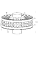
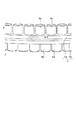
図1、図3に本発明の第一の実施の形態の振動体の一例を、図2に本実施の形態の振動子を有する振動型駆動装置の一例を示す。図1は振動体1の斜視図である。振動体1は、複数の振動部材2a、2bからなる振動部3と電気−機械エネルギー変換素子である圧電素子6を有する。ここでは、振動部3と圧電素子6が環状の例を示す。振動部材は、先端の摩擦面fsが駆動方向(周方向)に間隔をあけて並んだ、筒状の突起4を有する。筒状とは、高さ方向に垂直な断面が、円形、楕円形の場合だけでなく、多角形や角の丸い多角形の場合も含む。摩擦面の先には不図示の接触体が配置され、振動体1と接触体には、加圧機構によって、摩擦面の法線方向に加圧力が付与される。
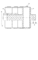
図10は、本発明の第二の実施の形態の振動体の断面図である。おもな構成は図1と同じである。この実施形態では、二つの振動部材の間に、支持部材である薄板状の支持板5を介挿することで、振動体から支持部となるフランジ部が径方向に延出している点で第一の実施の形態と異なる。
本実施の形態では、振動型駆動装置の例について図11乃至図14を用いて説明する。以下の図11乃至図14を用いて説明する装置において、振動型駆動装置としては、例えば第一の実施の形態または第二で説明した振動体を有する振動型駆動装置を用いることができる。
2 振動部材
3 振動部
4 突起
6 圧電素子
Claims (17)
- 第1の突起を有する第1の振動部材と、
第2の突起を有する第2の振動部材と、
前記第1の振動部材の、前記第1の突起が突出する側に設けられた電気―機械エネルギー変換素子と、
を有し、
前記第1の振動部材の、前記第1の突起が突出する側の反対側の面と、前記第2の振動部材の、前記第2の突起が突出する側の反対側の面は、直接的に又は間接的に接合されている振動体。 - 前記第1の振動部材は、前記第1の突起が突出する側に突出した第3の突起を有し、
前記第2の振動部材は、前記第2の突起が突出する側に突出した第4の突起を有する請求項1に記載の振動体。 - 前記第1の突起と前記第2の突起は、前記第1の突起が突出する方向から見たときに、前記第1の突起が突出する方向に垂直な方向において重なる位置にある請求項1または2に記載の振動体。
- 前記第2の突起の中心は、前記第1の突起が突出する方向から見たときに、前記第1の突起が突出する方向に垂直な方向において、前記第1の突起の中心と前記第3の突起の中心の間にある請求項2に記載の振動体。
- 前記第2の突起は、前記第1の突起が突出する方向から見たときに、前記第1の突起が突出する方向に垂直な方向において、前記第1の突起と前記第3の突起の間にある請求項2に記載の振動体。
- 前記第1の突起は、第1の壁部と、前記第1の突起の先端にある第1の接触部と、を有し、
前記第2の突起は、第2の壁部と、前記第2の突起の先端にある第2の接触部と、を有する請求項1乃至5のいずれか1項に記載の振動体。 - 前記第3の突起は中空構造であり、第3の壁部を有し、
前記第1の壁部の一部と前記第2の壁部の一部は、前記第1の突起が突出する方向から見たときに、前記第1の突起が突出する方向に垂直な方向において重なる位置にあり、前記第2の壁部の一部と前記第3の壁部の一部は重なる位置にある請求項6に記載の振動体。 - 前記第1の振動部材は接着剤を挟んで前記第2の振動部材に固定される請求項1乃至7のいずれか1項に記載の振動体。
- 前記第1の振動部材と前記第2の振動部材の間に支持部材を有する請求項1乃至7のいずれか1項に記載の振動体。
- 前記第1の突起及び前記第2の突起は、それぞれプレス加工によって形成されている請求項1乃至9のいずれか1項に記載の振動体。
- 前記第1の振動部材及び前記第2の振動部材は、それぞれ環状である請求項1乃至10のいずれか1項に記載の振動体。
- 請求項1乃至11のいずれか1項に記載の振動体と、前記振動体と接する被駆動体を有する振動型駆動装置。
- 前記被駆動体が、前記電気―機械エネルギー変換素子に交番電圧が印加されることで駆動される請求項12に記載の振動型駆動装置。
- アームと、
前記アームに接続された関節部を有し、
前記関節部は請求項1乃至11のいずれか1項に記載の振動体を有するロボット。 - 像担持体と、
前記像担持体に向き合って設けられた搬送ベルトと、
前記像担持体を回転駆動するよう構成された請求項1乃至11のいずれか1項に記載の振動体と、
を有する画像形成装置。 - 像担持体と、
前記像担持体に向き合って設けられた搬送ベルトと、
前記搬送ベルトを駆動するよう構成された請求項1乃至11のいずれか1項に記載の振動体と、
を有する画像形成装置。 - 撮像装置と、前記撮像装置が据え付けられた回転台と、前記回転台を駆動するよう構成された請求項1乃至11のいずれか1項に記載の振動体を有する振動型駆動装置と、を有する雲台装置。
Priority Applications (3)
| Application Number | Priority Date | Filing Date | Title |
|---|---|---|---|
| JP2015089580A JP6602041B2 (ja) | 2015-04-24 | 2015-04-24 | 振動体、振動型駆動装置、画像形成装置、ロボット、及び雲台装置 |
| US15/566,175 US10899004B2 (en) | 2015-04-24 | 2016-03-30 | Vibrator, vibration-type driving device, image forming apparatus, robot, and pan head |
| PCT/JP2016/001851 WO2016170741A1 (en) | 2015-04-24 | 2016-03-30 | Vibrator, vibration-type driving device, image forming apparatus, robot, and pan head |
Applications Claiming Priority (1)
| Application Number | Priority Date | Filing Date | Title |
|---|---|---|---|
| JP2015089580A JP6602041B2 (ja) | 2015-04-24 | 2015-04-24 | 振動体、振動型駆動装置、画像形成装置、ロボット、及び雲台装置 |
Publications (3)
| Publication Number | Publication Date |
|---|---|
| JP2016208732A JP2016208732A (ja) | 2016-12-08 |
| JP2016208732A5 JP2016208732A5 (ja) | 2018-11-15 |
| JP6602041B2 true JP6602041B2 (ja) | 2019-11-06 |
Family
ID=57143824
Family Applications (1)
| Application Number | Title | Priority Date | Filing Date |
|---|---|---|---|
| JP2015089580A Active JP6602041B2 (ja) | 2015-04-24 | 2015-04-24 | 振動体、振動型駆動装置、画像形成装置、ロボット、及び雲台装置 |
Country Status (3)
| Country | Link |
|---|---|
| US (1) | US10899004B2 (ja) |
| JP (1) | JP6602041B2 (ja) |
| WO (1) | WO2016170741A1 (ja) |
Families Citing this family (4)
| Publication number | Priority date | Publication date | Assignee | Title |
|---|---|---|---|---|
| JP7476021B2 (ja) * | 2020-07-27 | 2024-04-30 | キヤノン株式会社 | 振動型アクチュエータ、雲台、および電子機器 |
| JP7483547B2 (ja) * | 2020-08-05 | 2024-05-15 | キヤノン株式会社 | 振動型アクチュエータ、雲台、および電子機器 |
| CN112492175B (zh) * | 2020-12-08 | 2022-06-10 | 维沃移动通信有限公司 | 摄像模组 |
| JP7654424B2 (ja) * | 2021-03-08 | 2025-04-01 | キヤノン株式会社 | 振動型アクチュエータ及びそれを有する雲台、電子機器 |
Family Cites Families (6)
| Publication number | Priority date | Publication date | Assignee | Title |
|---|---|---|---|---|
| JP2968669B2 (ja) * | 1993-08-23 | 1999-10-25 | 株式会社豊田中央研究所 | 超音波モータのステータ及び超音波モータ |
| JPH08298792A (ja) | 1995-04-26 | 1996-11-12 | Canon Inc | 振動波駆動装置 |
| JP2000350481A (ja) * | 1999-06-04 | 2000-12-15 | Canon Inc | 振動波駆動装置および事務機 |
| JP4350208B2 (ja) * | 1999-06-17 | 2009-10-21 | キヤノン株式会社 | 振動波駆動装置 |
| JP4874610B2 (ja) * | 2005-09-16 | 2012-02-15 | Hoya株式会社 | 超音波モータ |
| JP5930595B2 (ja) * | 2010-04-06 | 2016-06-08 | キヤノン株式会社 | 振動型アクチュエータ、振動子及び振動子の製造方法 |
-
2015
- 2015-04-24 JP JP2015089580A patent/JP6602041B2/ja active Active
-
2016
- 2016-03-30 US US15/566,175 patent/US10899004B2/en active Active
- 2016-03-30 WO PCT/JP2016/001851 patent/WO2016170741A1/en not_active Ceased
Also Published As
| Publication number | Publication date |
|---|---|
| US10899004B2 (en) | 2021-01-26 |
| US20180093375A1 (en) | 2018-04-05 |
| JP2016208732A (ja) | 2016-12-08 |
| WO2016170741A1 (en) | 2016-10-27 |
Similar Documents
| Publication | Publication Date | Title |
|---|---|---|
| US10972019B2 (en) | Ultrasonic motor and lens driving apparatus | |
| JP6602041B2 (ja) | 振動体、振動型駆動装置、画像形成装置、ロボット、及び雲台装置 | |
| JP2017108615A (ja) | 振動型アクチュエータの駆動方法、振動型駆動装置及び機械装置 | |
| US20160126864A1 (en) | Vibration drive device in which separation between members by external force is suppressed, lens barrel, image pickup apparatus, and stage device | |
| US8035275B2 (en) | Vibration actuator, lens barrel, camera system and vibrating element | |
| JP6652289B2 (ja) | 振動型駆動装置、ロボット、画像形成装置及び撮像装置 | |
| JP2016027780A (ja) | 振動型アクチュエータ、レンズ鏡筒、撮像装置及び自動ステージ | |
| JP6324117B2 (ja) | 振動型駆動装置、ロボット、及び画像形成装置 | |
| JP2009201322A (ja) | 振動アクチュエータ、レンズ鏡筒、カメラ、振動アクチュエータの製造方法 | |
| JP2018186698A (ja) | 振動型駆動装置、振動型駆動装置の制御方法、プログラム、ロボット、撮像装置の雲台及び画像形成装置 | |
| JP5541281B2 (ja) | 振動アクチュエータ、レンズ鏡筒及びカメラ | |
| JP2015203130A (ja) | 弾性体の製造方法、振動型アクチュエータ及び画像形成装置 | |
| US9188931B2 (en) | Vibration type driving apparatus and image forming apparatus | |
| JP6436800B2 (ja) | 振動型駆動装置に用いられる弾性体の製造方法、振動型駆動装置、ロボット及び撮像装置 | |
| JP7331209B2 (ja) | 振動型駆動装置、振動型駆動装置の制御方法、プログラム、ロボット、撮像装置の雲台及び画像形成装置 | |
| JP2006014512A (ja) | 超音波モータ | |
| JP2005192276A (ja) | 振動型アクチュエータ及び振動型アクチュエータを用いた装置 | |
| JP2010148160A (ja) | 振動波モータ用の負荷トルク変動装置及び画像形成装置 | |
| JP2005223994A (ja) | 振動型アクチュエータ及び画像処理装置 | |
| JP2006067707A (ja) | 超音波モータおよび鏡枠移動機構 | |
| JP2003084521A (ja) | 画像形成装置 | |
| JP2019146349A (ja) | 振動型アクチュエータ及び電子機器 | |
| JP5109398B2 (ja) | アクチュエータ、光スキャナ、および画像形成装置 | |
| JP2016140141A (ja) | 振動型駆動装置及びその駆動方法、並びに撮像装置 |
Legal Events
| Date | Code | Title | Description |
|---|---|---|---|
| A621 | Written request for application examination |
Free format text: JAPANESE INTERMEDIATE CODE: A621 Effective date: 20180418 |
|
| A521 | Request for written amendment filed |
Free format text: JAPANESE INTERMEDIATE CODE: A523 Effective date: 20181004 |
|
| A131 | Notification of reasons for refusal |
Free format text: JAPANESE INTERMEDIATE CODE: A131 Effective date: 20190416 |
|
| A521 | Request for written amendment filed |
Free format text: JAPANESE INTERMEDIATE CODE: A523 Effective date: 20190611 |
|
| TRDD | Decision of grant or rejection written | ||
| A01 | Written decision to grant a patent or to grant a registration (utility model) |
Free format text: JAPANESE INTERMEDIATE CODE: A01 Effective date: 20190910 |
|
| A61 | First payment of annual fees (during grant procedure) |
Free format text: JAPANESE INTERMEDIATE CODE: A61 Effective date: 20191008 |
|
| R151 | Written notification of patent or utility model registration |
Ref document number: 6602041 Country of ref document: JP Free format text: JAPANESE INTERMEDIATE CODE: R151 |