JP6602003B2 - Temporary bicycle parking equipment - Google Patents
Temporary bicycle parking equipment Download PDFInfo
- Publication number
- JP6602003B2 JP6602003B2 JP2014172029A JP2014172029A JP6602003B2 JP 6602003 B2 JP6602003 B2 JP 6602003B2 JP 2014172029 A JP2014172029 A JP 2014172029A JP 2014172029 A JP2014172029 A JP 2014172029A JP 6602003 B2 JP6602003 B2 JP 6602003B2
- Authority
- JP
- Japan
- Prior art keywords
- bicycle
- temporary
- bicycle parking
- parking
- rack
- Prior art date
- Legal status (The legal status is an assumption and is not a legal conclusion. Google has not performed a legal analysis and makes no representation as to the accuracy of the status listed.)
- Expired - Fee Related
Links
- 239000002184 metal Substances 0.000 claims description 8
- 238000012546 transfer Methods 0.000 claims description 2
- 238000010276 construction Methods 0.000 description 34
- 238000005452 bending Methods 0.000 description 13
- 239000000758 substrate Substances 0.000 description 6
- 238000004873 anchoring Methods 0.000 description 4
- 229910000831 Steel Inorganic materials 0.000 description 3
- 239000010959 steel Substances 0.000 description 3
- 238000003780 insertion Methods 0.000 description 2
- 230000037431 insertion Effects 0.000 description 2
- 238000012544 monitoring process Methods 0.000 description 2
- 238000005096 rolling process Methods 0.000 description 2
- 238000013461 design Methods 0.000 description 1
- 230000000694 effects Effects 0.000 description 1
- 238000002474 experimental method Methods 0.000 description 1
- 239000000463 material Substances 0.000 description 1
- 238000012986 modification Methods 0.000 description 1
- 230000004048 modification Effects 0.000 description 1
- 238000000926 separation method Methods 0.000 description 1
- 238000010008 shearing Methods 0.000 description 1
- 238000003466 welding Methods 0.000 description 1
Images


Landscapes
- Refuge Islands, Traffic Blockers, Or Guard Fence (AREA)
Description
本発明は、仮設駐輪装置に関するものであり、より詳細には、建設工事等の工事現場や、イベント会場等に設営され、比較的短期間の使用の後、解体撤去される仮設駐輪装置に関するものである。 The present invention relates to a temporary bicycle parking device, and more particularly, a temporary bicycle parking device that is installed at a construction site such as construction work or an event venue and is dismantled and removed after a relatively short period of use. It is about.
放置自転車等のための交通障害を解消すべく、鉄道の駅の周辺や、集合住宅等には、自転車を駐輪するための駐輪施設が設営される。この種の駐輪施設には、比較的狭い空間に多数の自転車を効率的に収容するための自転車収納設備が常設される。一般に、自転車収納設備は、前後の支持梁又は支持レールと、支持梁間又はレール間に架設された多数の自転車載置台とを備え、自転車載置台は、所定間隔を隔てて平行に配列される。この種の自転車収納設備は、例えば、特開2011-121567号公報、特開2007-203791号公報及び特開2003-261080号公報(特許文献1〜3)等に記載されているが、いずれも、比較的長期に亘って駐輪施設のコンクリート基礎面、コンクリート床面又はコンクリート舗装面等に設置される恒久的な機械式駐輪設備である。
In order to eliminate traffic obstacles for parked bicycles, bicycle parking facilities are set up in the vicinity of railway stations and apartment buildings. In this type of bicycle parking facility, a bicycle storage facility for efficiently storing a large number of bicycles in a relatively small space is permanently installed. In general, a bicycle storage facility includes front and rear support beams or support rails, and a large number of bicycle mounts installed between the support beams or between the rails, and the bicycle mounts are arranged in parallel at a predetermined interval. This type of bicycle storage equipment is described in, for example, Japanese Patent Application Laid-Open No. 2011-121567, Japanese Patent Application Laid-Open No. 2007-203791, and Japanese Patent Application Laid-Open No. 2003-261080 (
他方、建築、土木及びプラント等の工事現場や、各種イベント会場等(以下、「工事現場等」という。)においては、一時的に数百人〜数千人の工事関係者、イベント関係者等が勤務し又は作業に従事することがあり、多くの場合、場内の移動に自転車が使用されるので、多数の自転車を駐輪するための仮設駐輪場が必要とされる。この種の仮設駐輪場は、ある程度の面積の地面、舗装路等を駐輪場として区画し、工事関係者等が、仮設駐輪場内の空きスペースに任意に自転車を駐輪させることができるようにした駐輪空間であるにすぎない。 On the other hand, at construction sites such as architecture, civil engineering, and plants, and various event venues (hereinafter referred to as “construction sites”), there are temporarily several hundred to several thousand construction personnel, event personnel, etc. In many cases, bicycles are used to move around the site, so that a temporary bicycle parking lot for parking a large number of bicycles is required. This type of temporary bicycle parking lot has a certain area of ground, paved road, etc. as a bicycle parking lot, and construction personnel etc. can arbitrarily park bicycles in the empty space in the temporary bicycle parking lot. It's just space.
しかしながら、工事現場等の仮設駐輪場は、比較的限られた面積に設営されることが多いことから、自転車が不規則に駐輪されると、多数の自転車を効率的に収容し難い状況が生じる。このため、自転車を整列駐輪するために、交通警備員、自転車整理作業員等の人為的な監視・管理や、整列駐輪作業等に依存せざるを得ない事情がある。 However, since temporary bicycle parking lots such as construction sites are often set up in a relatively limited area, if bicycles are parked irregularly, it may be difficult to efficiently accommodate a large number of bicycles. . For this reason, in order to arrange and park bicycles, there is a situation in which it is necessary to rely on artificial monitoring and management of traffic guards, bicycle rearranging workers, etc., and bicycle parking arrangements.
これに対し、自転車使用者が自ら整列駐輪し得るように常設式の機械式駐輪設備を仮設駐輪場に設置することも考慮し得る。しかし、この種の設備は、いずれも、長期間の使用を前提とした比較的複雑、高強度且つ高価な装置であり、数カ月〜数週間程度の比較的短期間の使用を前提とした工事現場等の駐輪設備として経済的に使用し得る性質のものではない。 On the other hand, it is also possible to consider installing a permanent mechanical bicycle parking facility in the temporary bicycle parking lot so that the bicycle user can arrange and park the bicycle. However, all of these types of equipment are relatively complex, high-strength, and expensive equipment that is assumed to be used for a long period of time, and construction sites that are assumed to be used for a relatively short period of several months to several weeks. It is not of a nature that can be used economically as a bicycle parking facility.
仮に、工事現場等の仮設駐輪場において機械式駐輪設備を使用した場合、短期間の使用の後に駐輪設備を廃棄し難いことから、工事等の完了後に駐輪設備を他の工事現場等に移設して再利用することが望ましい。しかし、従来の機械式駐輪設備は、簡易に解体して他の駐輪場に移設するような使用形態を前提としたものではなく、このような使用形態に適した構造を備えていない。 If a mechanical bicycle parking facility is used at a temporary bicycle parking lot at a construction site, it is difficult to dispose of the bicycle parking facility after a short period of use. It is desirable to relocate and reuse. However, conventional mechanical bicycle parking facilities are not premised on a usage pattern that can be easily disassembled and transferred to another bicycle parking lot, and do not have a structure suitable for such a usage pattern.
即ち、工事現場等の仮設駐輪場において仮設機材として使用可能な機械式駐輪設備が存在しないことから、工事現場等の仮設駐車場では、交通警備員、自転車整理作業員等の人為的な監視・管理や、整列駐輪作業等に依存して自転車の効率的駐輪を可能にするか、或いは、工事現場等で使用される自転車の台数を制限するといった運用上の対策を採用せざるを得ない。 In other words, since there are no mechanical bicycle parking facilities that can be used as temporary equipment at temporary bicycle parking lots at construction sites, etc., at the temporary parking lots at construction sites, etc., Depending on management and bicycle parking, etc., it will be possible to park bicycles efficiently, or operational measures such as limiting the number of bicycles used at construction sites must be adopted. Absent.
しかし、工事現場等の仮設駐輪場において簡易に機械式駐輪設備を構築し、工事等の完了後に機械式駐輪設備を他の工事現場等に比較的簡単に移設して再利用することが可能であれば、人為的な監視・管理等に依存することなく、しかも、限られた工事現場等の駐輪スペースに比較的多数の自転車を効率的に駐輪することが可能となると考えられる。 However, it is possible to easily construct a mechanical bicycle parking facility at a temporary bicycle parking lot at a construction site, etc., and to move the mechanical bicycle parking facility to another construction site, etc. relatively easily after the construction is completed. If so, it will be possible to efficiently park a relatively large number of bicycles in a limited parking space such as a construction site without depending on artificial monitoring and management.
本発明は、このような事情に鑑みてなされたものであり、その目的とするところは、工事現場等の仮設駐輪場において機械式駐輪設備を簡易に構築することができ、工事等の完了後に他の工事現場等に移設して機械式駐輪設備を容易に再構築することができる仮設駐輪装置を提供することにある。 The present invention has been made in view of such circumstances, and the purpose of the present invention is that a mechanical bicycle parking facility can be easily constructed in a temporary bicycle parking lot such as a construction site, and after completion of the construction or the like. It is an object of the present invention to provide a temporary bicycle parking device that can be relocated to another construction site or the like to easily reconstruct mechanical bicycle parking equipment.
本発明は、上記目的を達成すべく、自転車の車輪接地面の上方域に架設された横架材に着脱可能に固定される係留具と、車輪接地面の上方域に位置する前記係留具に一体的に連結され且つ曲げ加工した金属管により形成された駐輪ラックとを有し、
前記駐輪ラックは、該駐輪ラックの先端部分に連結され且つ前記駐輪ラック及び前記横架材の間で荷重を伝達する前記係留具を介して前記横架材に一体的に連結されるとともに、自転車の前輪を部分的に収容可能な前輪収容領域を形成し、前記駐輪ラックは、前記係留具と前記駐輪ラックとの連結部の近傍に配置された接地脚を有することを特徴とする仮設駐輪装置を提供する。
In order to achieve the above object, the present invention provides a mooring device that is detachably fixed to a horizontal member erected in the upper region of a bicycle wheel ground surface, and the mooring device that is located in an upper region of the wheel ground surface. A bicycle rack formed by integrally connected and bent metal tubes,
The bicycle parking rack is integrally connected to the horizontal member through the tether to transfer loads between and connected to the distal end portion of the bicycle rack the bicycle rack and the horizontal member In addition, a front wheel storage area capable of partially storing a front wheel of a bicycle is formed, and the parking rack includes a grounding leg disposed in the vicinity of a connection portion between the mooring device and the parking rack. A temporary bicycle parking device is provided.
本発明の上記構成によれば、駐輪ラックは、係留具を介して横架材に一体的に連結され、或いは、横架材によって片持ち梁式の支持構造で支持されるので、接地面の支持力を必ずしも要しない。このため、接地面は、平坦な整地・転圧面や、平坦なコンクリート基礎面、コンクリート床面、コンクリート舗装面等の施工を必ずしも要するものではなく、軟弱な地盤面、砂利敷き面、不陸地盤面等を接地面として仮設駐輪装置を設置することができる。従って、本発明の仮設駐輪装置によれば、係留具によって駐輪ラックを横架材に取付けることにより、容易に駐輪装置を構築することができ、係留具を解体することにより、容易に駐輪装置を解体することができる。また、係留具及び駐輪ラックは、比較的容易に他の工事現場等に搬送し、上記の如く駐輪装置を再構築することができるので、異なる工事現場等の間で駐輪装置を容易に移設することができる。 According to the above configuration of the present invention, the parking rack is integrally connected to the horizontal member via the mooring device, or is supported by the horizontal member on the cantilever type support structure. The support force is not necessarily required. For this reason, the ground contact surface does not necessarily require the construction of flat ground leveling / rolling surface, flat concrete foundation surface, concrete floor surface, concrete pavement surface, etc. A temporary bicycle parking device can be installed using the ground as a ground plane. Therefore, according to the temporary parking device of the present invention, it is possible to easily construct the parking device by attaching the parking rack to the horizontal member with the mooring device, and it is easy to disassemble the mooring device. The bicycle parking device can be dismantled. In addition, mooring fixtures and parking racks can be transported to other construction sites relatively easily, and the parking system can be reconstructed as described above. Can be relocated.
好ましくは、係留具は、横架材に固定可能な仮設工事用クランプ部材からなる。本発明者の実験によれば、仮設足場等の構築において使用される通常の仮設工事用クランプ部材は、係留具及び横架材の連結部に作用する曲げ応力、剪断応力等に耐える緊結強度又は緊締強度を十分に保有する。更に好ましくは、係留具と駐輪ラックとの連結部は、係留具に対する駐輪ラックの高さ位置を調節するための連結位置調節手段(72,73)を備える。 Preferably, the mooring tool is composed of a temporary work clamping member that can be fixed to the horizontal member. According to the inventor's experiment, a normal clamp member for temporary work used in the construction of a temporary scaffold or the like has a binding strength or a bending strength acting on a connecting portion of a mooring tool and a horizontal member, Sufficient tightening strength. More preferably, the connecting portion between the mooring device and the bicycle parking rack includes connection position adjusting means (72, 73) for adjusting the height position of the bicycle parking rack with respect to the mooring device.
また、上記構成の駐輪ラックは、接地脚及び/又は車輪止め部材を接地面に接地させることにより、接地面によっても駐輪ラックを支持することができる。 Moreover, bicycle rack of the above configuration, the contact Chiashi and / or chock members by grounded to the ground plane, it is possible to support the bicycle rack by the ground plane.
好ましくは、上記駐輪ラックを構成する金属管は、15〜30mmの外形を有し、上記前方湾曲部は、25〜40mmの曲率半径(内径)を有し、上記後方湾曲部は、40〜60mmの曲率半径(内径)を有する。金属管は、前方湾曲部及び後方湾曲部によって所定距離(S1)離間した平行な直管部を形成する。直管部の離間距離(S1)は、例えば、55〜80mmの範囲内に設定される。更に好ましくは、後方湾曲部から前輪挿入方向に延びる直管部の先端部分を相互連結する基盤部が設けられ、基盤部は、上記係留具に一体的に連結される。所望により、基盤部は、係留具の保持部を上下方向に相対変位可能に収容するガイド溝と、保持部に突設されたボルトが貫通可能なスロット(長孔)形態のボルト挿通孔とを有し、基盤部は、係留具に対して高さ調節可能に連結される。
Preferably, the metal tube constituting the bicycle parking rack has an outer shape of 15 to 30 mm, the front curve has a
本発明の仮設駐輪装置によれば、工事現場等の仮設駐輪場において機械式駐輪設備を簡易に構築することができ、工事等の完了後に他の工事現場等に移設して機械式駐輪設備を容易に再構築することができる。 According to the temporary bicycle parking apparatus of the present invention, mechanical bicycle parking equipment can be easily constructed in a temporary bicycle parking lot at a construction site, etc., and after completion of the construction, etc., it is moved to another construction site etc. Equipment can be easily rebuilt.
以下、添付図面を参照して、本発明の好適な実施例について詳細に説明する。 Hereinafter, preferred embodiments of the present invention will be described in detail with reference to the accompanying drawings.
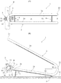
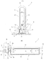
図1及び図2は、本発明の好適な実施例に係る仮設駐輪装置の構成を示す平面図、正面図、左側面図及び底面図であり、図3は、駐輪ラックの管体部分の構造を示す断面図である。 1 and 2 are a plan view, a front view, a left side view, and a bottom view showing a configuration of a temporary parking device according to a preferred embodiment of the present invention, and FIG. It is sectional drawing which shows this structure.
図1及び図2に示す如く、仮設駐輪装置1は、自転車の前輪を位置決めし且つ起立位置に保持するための駐輪ラック2と、駐輪ラック2を横架材B(破線で示す)に係留するための係留具3とから構成される。仮設駐輪装置1は、図1(B)及び図2(A)に示す如く、地面、床面又は舗装路面G(以下、「接地面G」という。)に配置され、接地面Gの上方に架設された横架材Bに固定される。
As shown in FIGS. 1 and 2, the
横架材Bは、建設工事の仮設足場(単管足場)において単管パイプ又は足場パイプ等の名称で使用される直径約40〜50mmの鋼管からなる。係留具3は、単管パイプ組み立て用クランプ、単管クランプ等の名称で知られる仮設工事用の緊結具又は緊締具であり、一般には、仮設足場(単管足場)において単管パイプ同士を緊結又は緊締するために使用される仮設機材である。係留具3は、保持部31と、保持部31の支軸34によって開閉可能に保持部31に支持された開閉部32と、開閉部32の先端部分を保持部31に連結する締付けボルト33とから構成される。保持部31、開閉部32及び締付けボルト33は、横架材Bを全体的に囲繞し、保持部31及び開閉部32は、締付けボルト33の締付け力によって横架材Bを挟持し、これにより、係留具3は、横架材Bに堅固に固定される。
The horizontal member B is made of a steel pipe having a diameter of about 40 to 50 mm and used as a single pipe or a scaffold pipe in a temporary scaffold (single pipe scaffold) for construction work. The
図3に示す如く、駐輪ラック2の管体部分は、真っ直ぐな鋼管(外径約20〜25mm)を湾曲部21、22において所定の曲率半径で曲げ加工した構造のものであり、駐輪ラック2の中心軸線X−Xに対して左右対称の形態を有する。使用において駐輪方向前方且つ上方に位置する湾曲部21(以下、「前方湾曲部21」という。)の曲率中心は、中心軸線X−X上に位置し、前方湾曲部21の曲率半径(内径)R1は、約33mmに設定される。使用において駐輪方向後方且つ下方に位置する湾曲部22(以下「後方湾曲部22」という。)の曲率中心は、接地面Gから高さH1(図1(B))を隔てた位置に位置し、後方湾曲部22の曲率半径(内径)R2は、約50mmに設定される。高さH1は、概ね80〜90mmの範囲内に設定される。
As shown in FIG. 3, the tubular portion of the
湾曲部21、22の間には、直管部24が延在する。左右の直管部24は、互いに平行に延びる。後方湾曲部22は、直管部25に連続する。左右の直管部25は、互いに平行に延びる。直管部25の先端部分26は、図1(B)に示す如く、基盤部7に一体的に連結され、基盤部7は、係留具3に着脱可能に連結される。左右の直管部24、25は、図1(A)に示す如く、水平距離S1を隔てる。距離S1は、約65mmに設定され、自転車の前輪を挿入可能な車輪収容空間αが左右の直管部24、25の間に形成される。
A
図1及び図2に示すように、接地脚5が直管部25の先端部分26に固定され、車輪止め部材6が後方湾曲部22の近傍において直管部25の下面に水平に固定される。
As shown in FIGS. 1 and 2, the
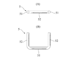
図4及び図5は、接地脚及び基盤部の構造を示す平面図及び正面図である。 4 and 5 are a plan view and a front view showing the structure of the grounding leg and the base part.
図4に示す如く、接地脚5は、直径約9mmの円形断面を有する金属製棒材をコの字形に曲げ加工してなる金属成形部材からなり、接地部51及び支柱部52を有する。車輪止め部材6は、直径約9mmの円形断面を有する真っ直ぐな金属製棒材からなる。車輪止め部材6は、図1及び図2に示すように、中心軸線X−Xと直交する方向に延び、左右の後方湾曲部22を架橋するように直管部25の下面に水平に固定される。
As shown in FIG. 4, the
接地脚5の支柱部52は、管体部分の下面に固定され、接地脚5の接地部51は、直管部25の中心軸線に対して直交する方向に延在する。接地部51は、接地面Gに接地し、車輪止め部材6も又、接地面Gに接地する。接地脚5及び車輪止め部材6が接地面Gに接地した状態では、直管部25は、後方湾曲部22から斜め上方且つ前方に延びる。
The
図2(B)に示す如く、基盤部7は、中心軸線X−Xと直交する方向に延び、左右の先端部分26を架橋するように直管部25の前端面に固定される。
As shown in FIG. 2B, the
基盤部7は、図5に示す如く、水平な長軸を有する長円形の基板71と、基板71の前側面に垂直に固定された左右一対のガイド部材72とから構成される。基板71の中心部には、上下方向の長軸を有するスロット(長孔)73が穿設される。基板71の左右の端部には、円形開口部74が穿設される。各円形開口部74は、管体部分の各先端部分26(図5に破線で示す)に整合する位置に配置される。各先端部分26は、溶接等の固着手段によって基板71に固定される。
As shown in FIG. 5, the
ガイド部材72は、係留具3の保持部31の幅と実質的に同一の距離S2を隔てて離間する。距離S2は、係留具3の保持部31の幅と実質的に同じ寸法、或いは、保持部31の幅よりも僅かに大きな寸法に設定され、ガイド部材72の間には、係留具3の保持部31を上下動可能に受入れるガイド溝75が形成される。なお、本例において、各ガイド部材72は、直径約9mmの円形断面を有する真っ直ぐな金属製棒材からなる。
The
図1及び図2に示す如く、係留具3の保持部31がガイド溝75に挿入される。保持部31に突設された連結ボルト36がスロット73を貫通し、ナット37が、連結ボルト36の先端部分に螺着する。保持部31は、ナット37の締付けにより、基盤部7に一体的に連結される。
As shown in FIGS. 1 and 2, the holding
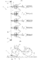
図6は、図1及び図2に示す仮設駐輪装置の使用状態を例示する平面図及び側面図である。図6には、接地面G上に複数の駐輪ラック2をE形配列に配置し、各自転車を各駐輪ラック2によって起立状態に保持した状態が示されている。
FIG. 6 is a plan view and a side view illustrating the use state of the temporary parking device shown in FIGS. 1 and 2. FIG. 6 shows a state in which a plurality of
横架材Bを架設するための鉛直杭Cが、接地面Gに立設される。鉛直杭Cは、横架材Bと同じく、直径約40〜50mmの鋼管からなり、鉛直杭Cの下部は、接地面Gの地盤等に埋入し、地盤等によって支持される。なお、鉛直杭Cに換えて、仮設足場、仮設構造物等の鉛直支柱を利用して横架材Bを架設しても良い。 A vertical pile C for laying the horizontal member B is erected on the ground contact surface G. The vertical pile C is made of a steel pipe having a diameter of about 40 to 50 mm, like the horizontal member B, and the lower portion of the vertical pile C is embedded in the ground of the ground contact surface G and supported by the ground. Instead of the vertical pile C, the horizontal member B may be constructed using vertical struts such as temporary scaffolds and temporary structures.
横架材Bは、直交クランプ等の仮設工事用クランプ部材Eによって鉛直杭Cの地上部分に固定される。横架材Bの中心軸線の高さH2(図1(B))は、基盤部7の高さ位置に相応して設定される。本例においては、高さH2は、約90mmに設定される。
The horizontal member B is fixed to the ground portion of the vertical pile C by a temporary work clamping member E such as an orthogonal clamp. The height H2 (FIG. 1B) of the central axis of the horizontal member B is set in accordance with the height position of the
係留具3は、図1及び図2に示す如く横架材Bを囲繞し、締付けボルト33の締付け力によって横架材Bに堅固に固定される。接地脚5及び車輪止め部材6は、接地面Gに接地する。かくして、係留具3に一体的に連結された各駐輪ラック2により、横架材Bと直交する方向に延びる車輪収容空間αを形成することができる。
As shown in FIGS. 1 and 2, the
駐輪ラック2の荷重は、係留具3を介して横架材Bに伝達し、横架材Bによって片持ち梁式(キャンチレバー式)の支持形態で支持される。係留具3には、横架材Bの中心軸線廻りの曲げモーメント等が作用するが、係留具3を構成する仮設工事用クランプ部材は、仮設足場等の安全性確保のために緊結強度又は緊締強度等を予め規定されており、係留具3及び横架材Bの連結部に作用する曲げ応力、剪断応力等に耐える緊結強度又は緊締強度を十分に保有することが判明した。
The load of the
このように駐輪ラック2が片持ち梁式の支持形態で横架材Bに支持されるので、接地脚5及び車輪止め部材6は、必ずしも駐輪ラック2の荷重を地盤面Gに伝達する必要はなく、従って、接地脚5及び車輪止め部材6を地盤面Gに接地させず、地盤面Gから若干浮き上がった状態に位置決めしても良い。また、地盤面Gは、駐輪ラック2の荷重を支持することを必ずしも要しないので、軟弱な地盤面や、砂利敷き面、不陸地盤面等であっても良く、従って、地盤面Gの整地・転圧や、コンクリート基礎、コンクリート床面、コンクリート舗装面等の施工を省略することができる。
Thus, since the
なお、基盤部7は、ナット37を過渡的に弛めて保持部31をガイド溝75内で上下方向にスライドさせ、スロット73の高さ範囲内で係留具3の高さ位置を上下方向に変位させることができる。従って、接地脚5を接地面Gに接地させる場合には、係留具3の高さ位置を調節し、接地脚5と接地面Gとの位置関係を調整することができる。
In addition, the
図6(A)に示す如く、所定間隔を隔てて複数の駐輪ラック2を横架材Bに固定することにより、複数の自転車を駐輪可能な駐輪設備を地盤G上に形成することができる。図6(B)に示す如く、自転車の前輪は、車輪止め部材6を乗り越えて車輪収容空間αに挿入される。前輪の下側後部は、車輪止め部材6に当接し、後方回転及び後方移動を制動又は阻止される。前輪は、左右の直管部24、25によって側方への傾倒を阻止されるので、自転車は、起立状態を維持する。
As shown in FIG. 6 (A), a plurality of
工事終了等により駐輪設備を撤去する場合、締付けボルト33の締付け力を解放して係留具3を開放することにより、駐輪ラック2を横架材Bから容易に撤去することができる。横架材Bは、クランプ部材Eの解放により、鉛直杭Cから容易に撤去することができ、鉛直杭Cは、地盤等から引き抜くことにより、撤去することができる。
When the bicycle parking facility is removed due to the completion of construction or the like, the
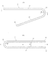
図7は、図1及び図2に示す仮設駐輪装置の他の使用状態を例示する平面図及び側面図であり、図8は、図1及び図2に示す仮設駐輪装置の更に他の使用状態を例示する平面図及び側面図である。図7に示す使用形態では、駐輪ラックは、上下二段配列に配置されており、図8に示す使用形態では、駐輪ラックは、王形配列に配置されている。 FIG. 7 is a plan view and a side view illustrating another use state of the temporary parking device shown in FIGS. 1 and 2, and FIG. 8 is still another example of the temporary parking device shown in FIGS. It is the top view and side view which illustrate a use condition. In the usage pattern shown in FIG. 7, the parking racks are arranged in an upper and lower two-stage arrangement, and in the usage pattern shown in FIG. 8, the parking racks are arranged in a king-shaped arrangement.
図7に示す如く、鉛直杭Cに対して横架材Bを上下二段に架設し、駐輪ラック2を上下の横架材Bに交互に取付けることにより、駐輪ラック2を上下二段配列に配置することができる。また、図8に示す如く、横架材Bの各側に駐輪ラック2を交互に取付けることにより、駐輪ラック2を王形配列に配置することができる。
As shown in FIG. 7, the horizontal rack B is installed in two vertical stages on the vertical pile C, and the
なお、図7に示す上下二段配列においては、上段の駐輪ラック2は、完全に空中に浮いた状態であるが、前述の如く、駐輪ラック2の荷重は、係留具3を介して横架材Bに伝達し、横架材Bによって片持ち梁式の支持形態で支持される。
In the upper and lower two-stage arrangement shown in FIG. 7, the
以上、本発明の好適な実施例について詳細に説明したが、本発明は上記実施例に限定されるものではなく、特許請求の範囲に記載された本発明の範囲内で種々の変形又は変更が可能である。 The preferred embodiments of the present invention have been described in detail above. However, the present invention is not limited to the above-described embodiments, and various modifications or changes can be made within the scope of the present invention described in the claims. Is possible.
例えば、上記実施例では、直管形態の横架材に対して駐輪ラックを取付けているが、湾曲した横架材や、平面視多角形又は円形(環状)の枠体を構成する横架材等に駐輪ラックを取付けても良い。 For example, in the above-described embodiment, the parking rack is attached to the horizontal tube-shaped horizontal member. However, the horizontal member that forms a curved horizontal member or a polygonal or circular (annular) frame body in plan view. A bicycle parking rack may be attached to the material.
また、上記実施例では、仮設工事用クランプ部材を係留具として使用しているが、同等の強度を保有する他の構造又は種類の係留具によって駐輪ラックを横架材に取付けても良い。 Moreover, in the said Example, although the clamp member for temporary construction is used as a mooring tool, you may attach a parking rack to a horizontal member with the mooring tool of the other structure or kind which has equivalent intensity | strength.
更に、上記実施例では、駐輪ラック設置のための横架材を鉛直杭によって架設しているが、既存構造物の既設横架材や、仮設足場、仮設構造物等の構成部材に駐輪ラックを取付けることも可能である。 Furthermore, in the above embodiment, the horizontal member for installing the bicycle parking rack is installed by the vertical pile, but the bicycle is installed on the existing horizontal member of the existing structure, the temporary scaffolding, the temporary structure or the like. It is also possible to mount a rack.
また、上記実施例では、駐輪ラックは、曲げ変形管、基盤、車輪止め部材及び接地脚を一体化した構造のものであるが、例えば、可搬性、運搬容易性等を考慮して、曲げ変形管及び接地脚等を折り畳み式構造や、分解可能な構造に設計することも可能である。 In the above embodiment, the parking rack has a structure in which the bending deformation pipe, the base, the wheel stopper member, and the grounding leg are integrated. For example, in consideration of portability, ease of transport, etc. It is also possible to design the deformable tube and the grounding leg in a foldable structure or a structure that can be disassembled.
本発明は、仮設駐輪装置、殊に、建設工事等の工事現場や、イベント会場等に設営され、比較的短期間の使用の後、解体撤去される仮設駐輪装置に適用される。本発明の仮設駐輪設備によれば、工事現場等の仮設駐輪場において機械式駐輪設備を簡易に構築することができ、工事等の完了後に他の工事現場等に移設して機械式駐輪設備を簡易に再構築することができるので、その実用的効果は、顕著なるものがある。 The present invention is applied to a temporary bicycle parking device, in particular, a temporary bicycle parking device that is installed at a construction site such as a construction work or an event venue, and is dismantled and removed after a relatively short period of use. According to the temporary bicycle parking facility of the present invention, the mechanical bicycle parking facility can be easily constructed at the temporary bicycle parking lot at the construction site, etc., and after completion of the construction etc., the mechanical bicycle parking facility is moved to the other construction site etc. Since the equipment can be easily reconstructed, its practical effect is remarkable.
1 仮設駐輪装置
2 駐輪ラック
3 係留具
5 接地脚
6 車輪止め部材
7 基盤部
21 前方湾曲部
22 後方湾曲部
24、25 直管部
26 先端部分
71 基板
72 ガイド部材
73 スロット
75 ガイド溝
α 車輪収容空間
G 接地面
B 横架材
DESCRIPTION OF
Claims (1)
前記駐輪ラックは、該駐輪ラックの先端部分に連結され且つ前記駐輪ラック及び前記横架材の間で荷重を伝達する前記係留具を介して前記横架材に一体的に連結されるとともに、自転車の前輪を部分的に収容可能な前輪収容領域を形成し、前記駐輪ラックは、前記係留具と前記駐輪ラックとの連結部の近傍に配置された接地脚を有することを特徴とする仮設駐輪装置。 A mooring device that is detachably fixed to a horizontal member installed above the wheel grounding surface of the bicycle, and a metal tube that is integrally connected to the mooring device located above the wheel grounding surface and bent. And a bicycle parking rack formed by
The bicycle parking rack is integrally connected to the horizontal member through the tether to transfer loads between and connected to the distal end portion of the bicycle rack the bicycle rack and the horizontal member In addition, a front wheel storage area capable of partially storing a front wheel of a bicycle is formed, and the parking rack includes a grounding leg disposed in the vicinity of a connection portion between the mooring device and the parking rack. Temporary bicycle parking equipment.
Priority Applications (1)
| Application Number | Priority Date | Filing Date | Title |
|---|---|---|---|
| JP2014172029A JP6602003B2 (en) | 2014-08-26 | 2014-08-26 | Temporary bicycle parking equipment |
Applications Claiming Priority (1)
| Application Number | Priority Date | Filing Date | Title |
|---|---|---|---|
| JP2014172029A JP6602003B2 (en) | 2014-08-26 | 2014-08-26 | Temporary bicycle parking equipment |
Publications (2)
| Publication Number | Publication Date |
|---|---|
| JP2016043900A JP2016043900A (en) | 2016-04-04 |
| JP6602003B2 true JP6602003B2 (en) | 2019-11-06 |
Family
ID=55634848
Family Applications (1)
| Application Number | Title | Priority Date | Filing Date |
|---|---|---|---|
| JP2014172029A Expired - Fee Related JP6602003B2 (en) | 2014-08-26 | 2014-08-26 | Temporary bicycle parking equipment |
Country Status (1)
| Country | Link |
|---|---|
| JP (1) | JP6602003B2 (en) |
Families Citing this family (1)
| Publication number | Priority date | Publication date | Assignee | Title |
|---|---|---|---|---|
| JP7421813B2 (en) * | 2021-12-14 | 2024-01-25 | 株式会社リード | bicycle rack |
Family Cites Families (7)
| Publication number | Priority date | Publication date | Assignee | Title |
|---|---|---|---|---|
| JPS5622176U (en) * | 1979-07-31 | 1981-02-27 | ||
| JPH0256090U (en) * | 1988-10-18 | 1990-04-23 | ||
| US5992645A (en) * | 1997-08-01 | 1999-11-30 | Colony Incorporated | Bicycle rack |
| JP2003002267A (en) * | 2001-06-22 | 2003-01-08 | Shinichi Maekawa | Sliding type bicycle parking device |
| JP4594217B2 (en) * | 2005-07-01 | 2010-12-08 | 二郎 青山 | Bicycle parking equipment |
| JP2009091789A (en) * | 2007-10-06 | 2009-04-30 | Sugikou:Kk | Tightener |
| JP6173091B2 (en) * | 2013-07-24 | 2017-08-02 | イーバイスリー株式会社 | Bicycle parking equipment and bicycle parking equipment |
-
2014
- 2014-08-26 JP JP2014172029A patent/JP6602003B2/en not_active Expired - Fee Related
Also Published As
| Publication number | Publication date |
|---|---|
| JP2016043900A (en) | 2016-04-04 |
Similar Documents
| Publication | Publication Date | Title |
|---|---|---|
| KR101687733B1 (en) | Deckroad guardrail assembly | |
| US9057172B2 (en) | Anchoring system | |
| KR101602953B1 (en) | height-adjustable support device of photovoltic module | |
| KR100991868B1 (en) | Guardrail | |
| GB2458312A (en) | Fence Panel Support Apparatus | |
| KR101406035B1 (en) | Pier for Bridge and Construction Method thereof | |
| JP6294601B2 (en) | Suspended scaffolding panel, suspension scaffold construction method and suspended scaffold panel unit | |
| CN106939690A (en) | The anti-load-bearing scaffold that inclines of one kind | |
| JP6468612B2 (en) | Method for assembling formwork support for tunnel lining concrete molding | |
| KR101428742B1 (en) | A Sidewalk Enlargement Installation | |
| KR101913668B1 (en) | A prefabricated scaffolding device which can work aheat power plant | |
| EP2578774B1 (en) | Support for containment system | |
| JP6602003B2 (en) | Temporary bicycle parking equipment | |
| CN201416263Y (en) | Disc bolt type scaffold | |
| CN201148732Y (en) | Molding plate horizontal bracing apparatus | |
| KR20100040197A (en) | Underground steel pipe structure and constructing method thereof | |
| KR20120047331A (en) | Safety net for bridges | |
| KR102470452B1 (en) | Temporary Structure for Bridge Inspection | |
| KR102370425B1 (en) | The safety rail of the formwork | |
| JP5706673B2 (en) | Vehicle forced stop device | |
| KR200430532Y1 (en) | Handrail support rod coupling structure | |
| KR101428748B1 (en) | A Sidewalk Enlargement Installation | |
| KR200460577Y1 (en) | Handrail | |
| ES2229895A1 (en) | Recoverable formwork system for floor, has multiple different longitudinal joists assembled together by springs for fixing struts, and intermediate transverse cross cantilever holder pieces arranged with panels | |
| CN119754550B (en) | A structural support system |
Legal Events
| Date | Code | Title | Description |
|---|---|---|---|
| A621 | Written request for application examination |
Free format text: JAPANESE INTERMEDIATE CODE: A621 Effective date: 20170726 |
|
| A131 | Notification of reasons for refusal |
Free format text: JAPANESE INTERMEDIATE CODE: A131 Effective date: 20180329 |
|
| A977 | Report on retrieval |
Free format text: JAPANESE INTERMEDIATE CODE: A971007 Effective date: 20180328 |
|
| A521 | Request for written amendment filed |
Free format text: JAPANESE INTERMEDIATE CODE: A523 Effective date: 20180512 |
|
| A521 | Request for written amendment filed |
Free format text: JAPANESE INTERMEDIATE CODE: A523 Effective date: 20180522 |
|
| A02 | Decision of refusal |
Free format text: JAPANESE INTERMEDIATE CODE: A02 Effective date: 20181010 |
|
| A521 | Request for written amendment filed |
Free format text: JAPANESE INTERMEDIATE CODE: A523 Effective date: 20181222 |
|
| A521 | Request for written amendment filed |
Free format text: JAPANESE INTERMEDIATE CODE: A821 Effective date: 20181225 |
|
| A911 | Transfer to examiner for re-examination before appeal (zenchi) |
Free format text: JAPANESE INTERMEDIATE CODE: A911 Effective date: 20190118 |
|
| A912 | Re-examination (zenchi) completed and case transferred to appeal board |
Free format text: JAPANESE INTERMEDIATE CODE: A912 Effective date: 20190222 |
|
| A521 | Request for written amendment filed |
Free format text: JAPANESE INTERMEDIATE CODE: A523 Effective date: 20190902 |
|
| A61 | First payment of annual fees (during grant procedure) |
Free format text: JAPANESE INTERMEDIATE CODE: A61 Effective date: 20191008 |
|
| R150 | Certificate of patent or registration of utility model |
Ref document number: 6602003 Country of ref document: JP Free format text: JAPANESE INTERMEDIATE CODE: R150 |
|
| LAPS | Cancellation because of no payment of annual fees |