JP6584085B2 - Optical system and imaging apparatus - Google Patents
Optical system and imaging apparatus Download PDFInfo
- Publication number
- JP6584085B2 JP6584085B2 JP2015028902A JP2015028902A JP6584085B2 JP 6584085 B2 JP6584085 B2 JP 6584085B2 JP 2015028902 A JP2015028902 A JP 2015028902A JP 2015028902 A JP2015028902 A JP 2015028902A JP 6584085 B2 JP6584085 B2 JP 6584085B2
- Authority
- JP
- Japan
- Prior art keywords
- optical system
- lens
- group
- lens group
- refractive power
- Prior art date
- Legal status (The legal status is an assumption and is not a legal conclusion. Google has not performed a legal analysis and makes no representation as to the accuracy of the status listed.)
- Active
Links
Images


Description
本件発明は、光学系及び撮像装置に関し、特に、デジタルスチルカメラやデジタルビデオカメラ等の固体撮像素子を用いた撮像装置に好適な光学系及び当該光学系を備えた撮像装置に関する。 The present invention relates to an optical system and an imaging apparatus, and more particularly to an optical system suitable for an imaging apparatus using a solid-state imaging device such as a digital still camera or a digital video camera, and an imaging apparatus including the optical system.
従来より、デジタルスチルカメラ、デジタルビデオカメラ等の固体撮像素子を用いた撮像装置が普及している。特に、近年の撮像光学系の高性能化、小型化等に伴い、小型の撮像システムの普及が急速に進んでいる。 Conventionally, imaging devices using solid-state imaging devices such as digital still cameras and digital video cameras have become widespread. In particular, with the recent enhancement of performance and size of imaging optical systems, the spread of small imaging systems is rapidly progressing.
このような小型の撮像システムの光学系として、種々の単焦点光学系が提案されている。例えば、特許文献1には、物体側から順に、正の屈折力を有する前群と、開放絞りと、負の屈折力を有する後群とを備えた焦点距離の比較的長い単焦点光学系が記載されている。一般に、焦点距離の長い望遠レンズでは、焦点距離が長くなるに従って、色収差が多く発生する。そこで、例えば、特許文献1に記載の単焦点光学系では、光路内に回折格子面を配置し、この回折格子により色収差の補正を行うことで、良好な結像性能を得ている。 Various single focus optical systems have been proposed as an optical system for such a small imaging system. For example, Patent Document 1 discloses, in order from the object side, a single focal point optical system having a relatively long focal length including a front group having a positive refractive power, an open aperture, and a rear group having a negative refractive power. Are listed. In general, in a telephoto lens having a long focal length, more chromatic aberration occurs as the focal length becomes longer. Therefore, for example, in the single focus optical system described in Patent Document 1, a favorable diffraction performance is obtained by disposing a diffraction grating surface in the optical path and correcting chromatic aberration with this diffraction grating.
しかしながら、特許文献1に記載の光学系は、光学系を構成するレンズの枚数が多く、光学系の小型化が十分に図られていない。また、当該光学系のFnoは2.8よりも大きく、明るさが不足している。近年、小型の撮像システムの光学系では、より一層の小型化が求められると共に、特に、単焦点光学系においてはFnoが2.8より明るい大口径化に対する要望が強い。 However, the optical system described in Patent Document 1 has a large number of lenses constituting the optical system, and the optical system is not sufficiently downsized. Further, Fno of the optical system is larger than 2.8, and the brightness is insufficient. In recent years, there has been a demand for further downsizing of an optical system of a small imaging system, and there is a strong demand for a large aperture whose Fno is brighter than 2.8 especially in a single focus optical system.
本発明の課題は、小型の撮像システムに好適な小型、高性能、且つ、大口径の光学系及び撮像装置を提供することにある。 An object of the present invention is to provide a small-sized, high-performance, large-aperture optical system and imaging apparatus suitable for a small-sized imaging system.
上記課題を解決するために、本件発明の光学系は、物体側から順に、正の屈折力を有する第1レンズ群と、負の屈折力を有する第2レンズ群と、正の屈折力を有する第3レンズ群とからなり、前記第1レンズ群と前記第3レンズ群とを光軸方向に固定し、前記第2レンズ群を光軸方向に移動させることで無限遠物体から有限距離物体への合焦を行い、前記第3レンズ群が、物体側から順に、物体側群と、開口絞りと、像側群とから構成されており、以下の条件を満足することを特徴とする。 In order to solve the above problems, the optical system of the present invention has, in order from the object side, a first lens group having a positive refractive power, a second lens group having a negative refractive power, and a positive refractive power. A third lens group, the first lens group and the third lens group are fixed in the optical axis direction, and the second lens group is moved in the optical axis direction to change from an infinite object to a finite distance object. The third lens group includes, in order from the object side, an object side group, an aperture stop, and an image side group, and satisfies the following conditions.
0.75 < f1/f < 1.30 ・・・(1)
0.722 ≦ f3/f < 1.10 ・・・(2a)
0 < Cr3af/f ・・・(5)
但し、
f1:前記第1レンズ群の焦点距離
f :当該光学系の焦点距離
f3:前記第3レンズ群の焦点距離
Cr3af:前記物体側群の最も物体側の面の曲率半径
である。
0.75 <f1 / f <1.30 (1)
0.722 ≦ f3 / f <1.10 (2a)
0 <Cr3af / f (5)
However,
f1: Focal length of the first lens group f: Focal length of the optical system
f3: focal length of the third lens group
Cr3af: the radius of curvature of the most object side surface of the object side group .
また、本件発明の撮像装置は、光学系と、当該光学系の像面側に、当該光学系によって形成された光学像を電気的信号に変換する撮像素子とを備えたことを特徴とする。 In addition, an imaging apparatus according to the present invention includes an optical system and an imaging element that converts an optical image formed by the optical system into an electrical signal on an image plane side of the optical system.
本件発明によれば、小型の撮像システムに好適な小型、高性能、且つ、大口径の光学系及び撮像装置を提供することができる。 According to the present invention, it is possible to provide a small-sized, high-performance, large-diameter optical system and an imaging apparatus suitable for a small-sized imaging system.
以下、本件発明に係る光学系及び撮像装置の実施の形態を説明する。 Hereinafter, embodiments of an optical system and an imaging apparatus according to the present invention will be described.
1.光学系
1−1.光学系の構成
本件発明に係る光学系は、物体側から順に、正の屈折力を有する第1レンズ群と、負の屈折力を有する第2レンズ群と、正の屈折力を有する第3レンズ群とからなり、第1レンズ群と第3レンズ群とを光軸方向に固定し、第2レンズ群を光軸方向に移動させることで無限遠物体から有限距離物体への合焦を行い、第3レンズ群が、物体側から順に、物体側群と、開口絞りと、像側群とから構成されており、後述する条件式(1)で表される条件を満足することを特徴とする。まず、本件発明に係る光学系の光学系の構成について説明する。
1. Optical system 1-1. Configuration of Optical System An optical system according to the present invention includes, in order from the object side, a first lens group having a positive refractive power, a second lens group having a negative refractive power, and a third lens having a positive refractive power. The first lens group and the third lens group are fixed in the optical axis direction, and the second lens group is moved in the optical axis direction to focus from an infinite object to a finite distance object. The third lens group includes, in order from the object side, an object side group, an aperture stop, and an image side group, and satisfies a condition represented by conditional expression (1) described later. . First, the configuration of the optical system of the optical system according to the present invention will be described.
本件発明に係る光学系では、最も物体側に配置される第1レンズ群が正の屈折力を有する。このため、第2レンズ群には第1レンズ群により収束された光が入射するため、第2レンズ群を外径の小さなレンズで構成することができ、第2レンズ群の小型化及び軽量化を図ることができる。また、第2レンズ群が負の屈折力を有するため、当該光学系をテレフォトタイプの構成とすることができる。このため、系全体の焦点距離よりもその光学全長を短くすることができ、系全体の小型化を図ることができる。そして、最も像面側に配置される第3レンズ群が正の屈折力を有するため、第3レンズ群において光束を集光することができ、大口径化を図ることができる。すなわち、本件発明によれば、正負正の3群構成を採用することで、小型の撮像システムに好適な小型で大口径の光学系を得ることができる。 In the optical system according to the present invention, the first lens unit disposed closest to the object side has a positive refractive power. For this reason, since the light converged by the first lens group is incident on the second lens group, the second lens group can be constituted by a lens having a small outer diameter, and the second lens group can be reduced in size and weight. Can be achieved. In addition, since the second lens group has a negative refractive power, the optical system can be configured as a telephoto type. For this reason, the optical total length can be made shorter than the focal length of the entire system, and the entire system can be reduced in size. Since the third lens group disposed closest to the image plane side has a positive refractive power, the light flux can be condensed in the third lens group, and the aperture can be increased. That is, according to the present invention, a small and large-diameter optical system suitable for a small imaging system can be obtained by adopting a positive and negative three-group configuration.
また、本件発明では、第1レンズ群と第3レンズ群とを光軸方向に固定し、第2レンズ群を光軸方向に移動させることで無限遠物体から有限距離物体への合焦を行う。合焦群である第2レンズ群は、上述したとおり、第1レンズ群の収束作用により、小型化及び軽量化が図られているため、第2レンズ群を移動させるための負荷が小さく迅速な合焦動作を行わせることができ、且つ、系全体を小型化することができる。以下、各レンズ群の構成について説明する。 In the present invention, the first lens group and the third lens group are fixed in the optical axis direction, and the second lens group is moved in the optical axis direction, thereby focusing from an infinite object to a finite distance object. . As described above, the second lens group, which is the focusing group, is reduced in size and weight by the convergence action of the first lens group, so that the load for moving the second lens group is small and quick. A focusing operation can be performed, and the entire system can be reduced in size. Hereinafter, the configuration of each lens group will be described.
(1)第1レンズ群
第1レンズ群は、正の屈折力を有し、後述する条件式(1)等を満足するものであれば、その具体的なレンズ構成は特に限定されるものではない。
(1) First lens group The first lens group is not particularly limited as long as it has positive refractive power and satisfies conditional expression (1) described later. Absent.
(2)第2レンズ群
第2レンズ群の構成についても、負の屈折力を有し、後述する条件式等を満足するものであれば、その具体的なレンズ構成は特に限定されるものではないが、正の屈折力を有するレンズを少なくとも1枚有することが好ましい。負の屈折力を有する第2レンズ群内に、正の屈折力を有するレンズを少なくとも1枚配置することにより、合焦時における第2レンズ群の移動に伴う色収差の変動を抑制することができ、被写体との距離によらず優れた結像性能を得ることができる。
(2) Second lens group The configuration of the second lens group is not particularly limited as long as it has negative refractive power and satisfies the conditional expressions described later. However, it is preferable to have at least one lens having a positive refractive power. By disposing at least one lens having a positive refractive power in the second lens group having a negative refractive power, fluctuations in chromatic aberration associated with movement of the second lens group during focusing can be suppressed. Excellent imaging performance can be obtained regardless of the distance to the subject.
さらに、第2レンズ群が正の屈折力を有するレンズ1枚と、負の屈折力を有するレンズ1枚とから構成されることが好ましい。第2レンズ群を正負各1枚のレンズから構成することにより、第2レンズ群をより小型及び軽量にすることができ、より迅速な合焦動作を行わせることができる。このとき、第2レンズ群を正の屈折力を有するレンズ1枚と、負の屈折力を有するレンズ1枚とを接合した接合レンズから構成することが好ましい。接合レンズにより第2レンズ群を構成することにより、組み立て時における製造誤差を低減することができ、製造誤差に起因する収差発生を抑制することができる。 Furthermore, it is preferable that the second lens group includes one lens having a positive refractive power and one lens having a negative refractive power. By configuring the second lens group from one positive and one negative lens, the second lens group can be made smaller and lighter, and a quicker focusing operation can be performed. At this time, it is preferable that the second lens group is composed of a cemented lens in which one lens having a positive refractive power and one lens having a negative refractive power are cemented. By configuring the second lens group with a cemented lens, manufacturing errors during assembly can be reduced, and aberrations due to manufacturing errors can be suppressed.
(3)第3レンズ群
本件発明では、第3レンズ群が、物体側から順に、物体側群と、開口絞りと、像側群とから構成されている。すなわち、第3レンズ群において、開口絞りを挟んで、物体側群と、像側群とを配置することにより、開口絞りの前後において、軸上光線及び軸外光線のいずれについても発生した収差を打ち消し合わせることが容易になり、高性能な光学系を得ることができる。
(3) Third Lens Group In the present invention, the third lens group is composed of an object side group, an aperture stop, and an image side group in order from the object side. That is, in the third lens group, the object-side group and the image-side group are arranged with the aperture stop interposed therebetween, so that aberrations generated for both on-axis rays and off-axis rays before and after the aperture stop are generated. It becomes easy to cancel each other, and a high-performance optical system can be obtained.
第3レンズ群において、物体側群及び像側群の屈折力は特に限定されるものではないが、像側群は正の屈折力を有することが好ましい。当該光学系において、最も像面側に正の屈折力を有するレンズ群を配置することにより、上述したとおり、当該光学系の大口径化を達成することができる。 In the third lens group, the refractive powers of the object side group and the image side group are not particularly limited, but the image side group preferably has a positive refractive power. In the optical system, by arranging a lens group having a positive refractive power closest to the image plane side, as described above, it is possible to achieve a large aperture of the optical system.
また、第3レンズ群において、物体側群の最も像面側の面の曲率半径、及び物体側群の最も物体側の面の曲率半径が、それぞれ後述する条件式(4)、条件式(5)、条件式(6)を満足することが好ましい。なお、この点については後述する。 In the third lens group, the radius of curvature of the most image side surface of the object side group and the radius of curvature of the most object side surface of the object side group are conditional expressions (4) and (5) described later, respectively. ) And conditional expression (6) are preferably satisfied. This point will be described later.
そして、像側群の最も像面側の面は、像面側に凸の形状を有することが好ましい。すなわち、当該光学系における最終面を像面側に凸の形状とすることにより、最終面において光束を集光させることができ、当該光学系のレンズ径を大きくすることなく、大口径化を達成することができる。 The surface closest to the image plane in the image side group preferably has a convex shape on the image plane side. That is, by making the final surface of the optical system convex toward the image surface side, the light flux can be condensed on the final surface, and a large aperture can be achieved without increasing the lens diameter of the optical system. can do.
(4)防振群
本件発明に係る光学系において、上述した第1レンズ群〜第3レンズ群のうち、いずれかのレンズ群の一部を光軸に垂直方向に移動させて、撮像時の振動等に起因する回転ブレ等を補正する防振群として用いてもよい。
(4) Anti-Vibration Group In the optical system according to the present invention, a part of any one of the first lens group to the third lens group described above is moved in the direction perpendicular to the optical axis to You may use as a vibration proof group which correct | amends the rotational shake etc. resulting from a vibration etc.
1−2.条件式
次に、本件発明に係る光学系が満足すべき条件、又は、満足することが好ましい条件について説明する。
1-2. Conditional Expressions Next, conditions that the optical system according to the present invention should satisfy or conditions that are preferably satisfied will be described.
1−2−1.条件式(1)
本件発明に係る光学系は、以下の条件を満足するものとする。
1-2-1. Conditional expression (1)
The optical system according to the present invention satisfies the following conditions.
0.75 < f1/f < 1.30 ・・・(1)
但し、
f1:第1レンズ群の焦点距離
f :当該光学系の焦点距離
である。
0.75 <f1 / f <1.30 (1)
However,
f1: Focal length of the first lens group f: Focal length of the optical system.
条件式(1)は、当該光学系の焦点距離に対する第1レンズ群の焦点距離の比を規定する式である。条件式(1)を満足することにより、当該光学系の焦点距離に対する第1レンズ群の焦点距離が適切な範囲内となり、当該光学系の小型化、高性能化を図ると共に、大口径化を達成することができる。 Conditional expression (1) defines the ratio of the focal length of the first lens group to the focal length of the optical system. By satisfying conditional expression (1), the focal length of the first lens unit with respect to the focal length of the optical system falls within an appropriate range, and the optical system is reduced in size and performance, and the aperture is increased. Can be achieved.
これに対して、条件式(1)の値が上限値以上になると、すなわち第1レンズ群の焦点距離が当該光学系の焦点距離に対して大きくなり過ぎると、光学系の全長が大きくなる共に、周辺光量の確保が困難になり、好ましくない。また、条件式(1)の値が下限値以下になると、すなわち第1レンズ群の焦点距離が当該光学系の焦点距離に対して小さくなり過ぎると、軸上色収差やコマ収差、像面湾曲を補正することが困難になり、良好な結像性能を得ることができず好ましくない。 On the other hand, if the value of conditional expression (1) is greater than or equal to the upper limit value, that is, if the focal length of the first lens group becomes too large relative to the focal length of the optical system, the total length of the optical system increases. Securing the amount of peripheral light becomes difficult, which is not preferable. If the value of conditional expression (1) is less than or equal to the lower limit, that is, if the focal length of the first lens group becomes too small with respect to the focal length of the optical system, axial chromatic aberration, coma aberration, and field curvature are reduced. It becomes difficult to correct, and good imaging performance cannot be obtained, which is not preferable.
これらの効果を得る上で、本件発明に係る光学系は、下記の条件式(1)’を満足することが好ましく、条件式(1)’’を満足することがより好ましく、条件式(1)’’’を満足することがさらに好ましい。 In obtaining these effects, the optical system according to the present invention preferably satisfies the following conditional expression (1) ′, more preferably satisfies the conditional expression (1) ″, and the conditional expression (1 It is further preferable to satisfy '' ''.
0.78 < f1/f < 1.20 ・・・(1)’
0.80 < f1/f < 1.10 ・・・(1)’’
0.80 < f1/f < 1.03 ・・・(1)’’’
0.78 <f1 / f <1.20 (1) ′
0.80 <f1 / f <1.10 (1) ''
0.80 <f1 / f <1.03 (1) '''
1−2−2.条件式(2)
本件発明に係る光学系において、第3レンズ群が以下の条件を満足することが好ましい。
1-2-2. Conditional expression (2)
In the optical system according to the present invention, it is preferable that the third lens group satisfies the following conditions.
0.50 < f3/f < 1.10 ・・・(2)
但し、
f3:第3レンズ群の焦点距離
である。
0.50 <f3 / f <1.10 (2)
However,
f3: focal length of the third lens unit.
条件式(2)は、本件発明に係る光学系の焦点距離に対する第3レンズ群の焦点距離の比を規定する式である。条件式(2)を満足することにより、当該光学系のより一層の小型化、高性能化を図ると共に、大口径化を達成することができる。 Conditional expression (2) defines the ratio of the focal length of the third lens group to the focal length of the optical system according to the present invention. By satisfying conditional expression (2), the optical system can be further reduced in size and performance, and a large aperture can be achieved.
これに対して、条件式(2)の値が上限値以上になると、すなわち当該光学系の焦点距離に対して第3レンズ群の焦点距離が大きくなり過ぎると、光学系の全長が大きくなるため、当該光学系の小型化が困難になる。これと同時に、第3レンズ群で光束を十分に収束させることができず、当該光学系の大口径化を図ることが困難になる。これらの点から、条件式(2)の値が上限値以上になることは好ましくない。また、条件式(2)の数値が下限値以下になると、すなわち当該光学系の焦点距離に対して第3レンズ群の焦点距離が小さくなり過ぎると、球面収差やコマ収差の補正が困難になり、好ましくない。 On the other hand, if the value of conditional expression (2) exceeds the upper limit value, that is, if the focal length of the third lens group becomes too large with respect to the focal length of the optical system, the total length of the optical system increases. This makes it difficult to reduce the size of the optical system. At the same time, the light flux cannot be sufficiently converged by the third lens group, and it becomes difficult to increase the diameter of the optical system. From these points, it is not preferable that the value of conditional expression (2) is equal to or greater than the upper limit value. If the numerical value of conditional expression (2) is less than or equal to the lower limit, that is, if the focal length of the third lens group becomes too small with respect to the focal length of the optical system, correction of spherical aberration and coma becomes difficult. It is not preferable.
これらの効果を得る上で、第3レンズ群は、下記の条件式(2)’を満足することが好ましく、条件式(2)’’を満足することがより好ましい。 In order to obtain these effects, the third lens group preferably satisfies the following conditional expression (2) ′, and more preferably satisfies the conditional expression (2) ″.
0.55 < f3/f < 1.00 ・・・(2)’
0.60 < f3/f < 0.95 ・・・(2)’’
0.55 <f3 / f <1.00 (2) ′
0.60 <f3 / f <0.95 (2) ''
1−2−3.条件式(3)
本件発明に係る光学系において、像側群が以下の条件を満足することが好ましい。
1-2-3. Conditional expression (3)
In the optical system according to the present invention, it is preferable that the image side group satisfies the following conditions.
0.01 < f3b/f < 3.00 ・・・(3)
但し、
f3b:像側群の焦点距離
である。
0.01 <f3b / f <3.00 (3)
However,
f3b: focal length of the image side group.
上記条件式(3)は、当該光学系の焦点距離に対する像側群の焦点距離の比を規定する式である。条件式(3)を満足することにより、当該光学系において最も像面側に配置される像側群により光束を集光することができるため、当該光学系の大口径化が容易になる。 Conditional expression (3) defines the ratio of the focal length of the image side group to the focal length of the optical system. When the conditional expression (3) is satisfied, the light beam can be condensed by the image side group arranged closest to the image plane in the optical system, so that the diameter of the optical system can be easily increased.
これに対して、条件式(3)の数値が上限値以上になると、すなわち像側群の焦点距離が当該光学系の焦点距離に対して大きくなり過ぎると、像側群により光束を十分に集光することができず、大口径化が困難になり、好ましくない。また、条件式(3)の値が下限値以下になると、すなわち像側群の焦点距離が当該光学系の焦点距離に対して小さくなり過ぎると、球面収差やコマ収差、像面湾曲の補正が困難になり、好ましくない。 On the other hand, if the numerical value of conditional expression (3) exceeds the upper limit value, that is, if the focal length of the image side group becomes too large with respect to the focal length of the optical system, the light beam is sufficiently collected by the image side group. It is not preferable because the light cannot be emitted and it becomes difficult to increase the diameter. If the value of conditional expression (3) is less than the lower limit, that is, if the focal length of the image side group becomes too small relative to the focal length of the optical system, spherical aberration, coma aberration, and field curvature are corrected. It becomes difficult and not preferable.
これらの効果を得る上で、像側群は、下記の条件式(3)’を満足することが好ましく、条件式(3)’’を満足することがより好ましく、条件式(3)’’’を満足することがさらに好ましい。 In obtaining these effects, the image side group preferably satisfies the following conditional expression (3) ′, more preferably satisfies the conditional expression (3) ″, and the conditional expression (3) ″ It is more preferable to satisfy '.
0.10 < f3b/f < 2.50 ・・・(3)’
0.20 < f3b/f < 2.00 ・・・(3)’’
0.30 < f3b/f < 1.50 ・・・(3)’’’
0.10 <f3b / f <2.50 (3) ′
0.20 <f3b / f <2.00 (3) ''
0.30 <f3b / f <1.50 (3) '''
1−2−4.条件式(4)
本件発明に係る光学系において、物体側群の最も像面側の面が以下の条件を満足することが好ましい。
1-2-4. Conditional expression (4)
In the optical system according to the present invention, it is preferable that the most image side surface of the object side group satisfies the following conditions.
0 < Cr3ar/f ・・・(4)
但し、
Cr3ar:前記物体側群の最も像面側の面の曲率半径
である。
0 <Cr3ar / f (4)
However,
Cr3ar: the radius of curvature of the surface closest to the image plane in the object side group.
上記条件式(4)は、当該光学系の焦点距離に対する物体側群の最も像面側の面の曲率半径の比を規定する式である。条件式(4)を満足する場合、物体側群の最も像面側に配置された面が像面側に凹の形状となり、球面収差や像面湾曲、サジタルフレアを良好に補正することができる。このため、少ないレンズ枚数でも良好な結像性能を得ることができ、小型、且つ、高性能な光学系を得ることが容易になる。 Conditional expression (4) defines the ratio of the radius of curvature of the surface closest to the image plane of the object side group to the focal length of the optical system. When the conditional expression (4) is satisfied, the surface disposed closest to the image plane in the object side group has a concave shape on the image plane side, so that spherical aberration, field curvature, and sagittal flare can be corrected well. . Therefore, good imaging performance can be obtained with a small number of lenses, and it becomes easy to obtain a compact and high-performance optical system.
これに対して、条件式(4)の値が下限値以下になると、すなわち物体側群の最も像面側に配置された面が平面若しくは像側に凸の形状となる。この場合、少ないレンズ枚数で球面収差や像面湾曲、サジタルフレアを良好に補正することが困難になる。このため、良好な結像性能を維持しつつ、当該光学系の小型化を図ることが困難になる。 On the other hand, when the value of the conditional expression (4) is equal to or lower than the lower limit value, that is, the surface arranged closest to the image plane in the object side group becomes a flat surface or a convex shape on the image side. In this case, it is difficult to satisfactorily correct spherical aberration, field curvature, and sagittal flare with a small number of lenses. For this reason, it is difficult to reduce the size of the optical system while maintaining good imaging performance.
これらの効果を得る上で、物体側群の最も像面側の面は、下記の条件式(4)’を満足することが好ましく、条件式(4)’’を満足することがより好ましく、条件式(4)’’’を満足することがさらに好ましい。 In obtaining these effects, the most image side surface of the object side group preferably satisfies the following conditional expression (4) ′, and more preferably satisfies the conditional expression (4) ″. More preferably, the conditional expression (4) ′ ″ is satisfied.
0.10 < Cr3ar/f < 2.00 ・・・(4)’
0.12 < Cr3ar/f < 1.50 ・・・(4)’’
0.15 < Cr3ar/f < 1.00 ・・・(4)’’’
0.10 <Cr3ar / f <2.00 (4) ′
0.12 <Cr3ar / f <1.50 (4) ''
0.15 <Cr3ar / f <1.00 (4) '''
1−2−5.条件式(5)
本件発明に係る光学系において、物体側群の最も物体側の面が以下の条件を満足することが好ましい。
1-2-5. Conditional expression (5)
In the optical system according to the present invention, it is preferable that the most object-side surface of the object-side group satisfies the following conditions.
0 < Cr3af/f ・・・(5)
但し、
Cr3af:前記物体側群の最も物体側の面の曲率半径
である。
0 <Cr3af / f (5)
However,
Cr3af: the radius of curvature of the most object side surface of the object side group.
上記条件式(5)は、当該光学系の焦点距離に対する物体側群の最も物体側の面の曲率半径の比を規定する式である。条件式(5)を満足する場合、物体側群の最も物体側の面が物体側に凸の形状となり、少ないレンズ枚数で球面収差や像面湾曲を良好に補正することができる。このため、小型、且つ、高性能な光学系を得ることが容易になる。 Conditional expression (5) defines the ratio of the radius of curvature of the most object-side surface of the object-side group to the focal length of the optical system. When the conditional expression (5) is satisfied, the most object-side surface of the object-side group has a convex shape on the object side, and spherical aberration and field curvature can be corrected well with a small number of lenses. For this reason, it becomes easy to obtain a compact and high-performance optical system.
これに対して、条件式(5)の値が下限値以下になると、物体側群の最も物体側の面が平面若しくは物体側に凹の形状となる。この場合、少ないレンズ枚数で球面収差や像面湾曲を良好に補正することが困難になり、良好な結像性能を維持しつつ、当該光学系の小型化を図ることが困難になる。 On the other hand, when the value of the conditional expression (5) is equal to or lower than the lower limit value, the most object side surface of the object side group becomes a flat surface or a concave shape on the object side. In this case, it is difficult to satisfactorily correct spherical aberration and curvature of field with a small number of lenses, and it is difficult to reduce the size of the optical system while maintaining good imaging performance.
これらの効果を得る上で、物体側群の最も物体側の面が、下記の条件式(5)’を満足することが好ましく、条件式(5)’’を満足することがより好ましく、条件式(5)’’’を満足することがさらに好ましく、条件式(5)’’’’を満足することが最も好ましい。 In obtaining these effects, the most object-side surface of the object-side group preferably satisfies the following conditional expression (5) ′, more preferably satisfies the conditional expression (5) ″. It is more preferable that the expression (5) ′ ″ is satisfied, and it is most preferable that the conditional expression (5) ″ ″ is satisfied.
0.10 < Cr3af/f < 20.00 ・・・(5)’
0.14 < Cr3af/f < 10.00 ・・・(5)’’
0.20 < Cr3af/f < 5.00 ・・・(5)’’’
0.26 < Cr3af/f < 2.00 ・・・(5)’’’’
0.10 <Cr3af / f <20.00 (5) ′
0.14 <Cr3af / f <10.00 (5) ''
0.20 <Cr3af / f <5.00 (5) '''
0.26 <Cr3af / f <2.00 (5) ''''
1−2−6.条件式(6)
本件発明に係る光学系において、物体側群の最も物体側の面と、物体側群の最も像面側の面とが以下の条件を満足することが好ましい。
1-2-6. Conditional expression (6)
In the optical system according to the present invention, it is preferable that the most object side surface of the object side group and the most image side surface of the object side group satisfy the following conditions.
1.0 < Cr3af/Cr3ar < 4.0 ・・・(6)
但し、Cr3af及びCr3arは上述のとおりである。
1.0 <Cr3af / Cr3ar <4.0 (6)
However, Cr3af and Cr3ar are as described above.
上記条件式(6)は、上記物体側群の最も像面側の面の曲率半径に対する上記物体側群の最も物体側の面の曲率半径の比を規定する式である。条件式(6)を満足する場合、少ないレンズ枚数で球面収差やコマ収差、サジタルフレアの補正をより良好に行うことができる。このため、小型、且つ、高性能な光学系を得ることがより容易になる。 The conditional expression (6) is an expression that defines the ratio of the radius of curvature of the most object-side surface of the object-side group to the radius of curvature of the most image-side surface of the object-side group. When the conditional expression (6) is satisfied, the spherical aberration, the coma aberration, and the sagittal flare can be corrected more satisfactorily with a small number of lenses. For this reason, it becomes easier to obtain a compact and high-performance optical system.
これに対して、物体側群の最も物体側の面と、物体側群の最も像面側の面とが条件式(6)を満足しない場合、少ないレンズ枚数で、球面収差やコマ収差、サジタルフレアを補正することが困難になり、良好な結像性能を得るには収差補正に要するレンズ枚数が増加し、当該光学系の大型化につながるため好ましくない。 On the other hand, when the surface closest to the object side in the object side group and the surface closest to the image plane in the object side group do not satisfy the conditional expression (6), spherical aberration, coma aberration, sagittal can be achieved with a small number of lenses. It becomes difficult to correct flare, and in order to obtain good imaging performance, the number of lenses required for aberration correction increases, leading to an increase in the size of the optical system.
これらの効果を得る上で、物体側群の最も物体側の面と、物体側群の最も像面側の面とが条件式(6)’を満足することがより好ましい。 In obtaining these effects, it is more preferable that the most object side surface of the object side group and the most image side surface of the object side group satisfy the conditional expression (6) ′.
1.0 < Cr3af/Cr3ar < 3.0 ・・・(6)’ 1.0 <Cr3af / Cr3ar <3.0 (6) '
1−2−7.条件式(7)
本件発明に係る光学系において、第2レンズ群が以下の条件を満足することが好ましい。
1-2-7. Conditional expression (7)
In the optical system according to the present invention, it is preferable that the second lens group satisfies the following conditions.
0.30 < |f2|/f < 1.20 ・・・(7)
但し、
f2:第2レンズ群の焦点距離
である。
0.30 <| f2 | / f <1.20 (7)
However,
f2: the focal length of the second lens group.
上記条件式(7)は、当該光学系の焦点距離に対する第2レンズ群の焦点距離の比を規定する式である。条件式(7)を満足する場合、第2レンズ群の屈折力が適正な範囲内となり、テレフォト比の小さな光学系を得ることができる。すなわち、焦点距離に比して光学全長の小さな小型の光学系を得ることができる。また、合焦群である第2レンズ群の屈折力が適正な範囲内となるため、合焦時の収差変動を抑制し、被写体との距離によらず、少ないレンズ枚数でも良好な結像性能を得ることができ、小型、且つ、高性能な光学系を得ることが容易になる。 The conditional expression (7) is an expression that defines the ratio of the focal length of the second lens group to the focal length of the optical system. When the conditional expression (7) is satisfied, the refractive power of the second lens group is within an appropriate range, and an optical system having a small telephoto ratio can be obtained. That is, a small optical system having a small optical total length compared to the focal length can be obtained. In addition, since the refractive power of the second lens group, which is the focusing group, is within an appropriate range, aberration variation during focusing is suppressed, and good imaging performance can be achieved with a small number of lenses regardless of the distance to the subject. It is easy to obtain a compact and high-performance optical system.
これに対して、条件式(7)の値が上限値以上になると、すなわち当該光学系の焦点距離に対して第2レンズ群の焦点距離が大きくなり過ぎると、テレフォト比を小さくすることが困難になる。この場合、光学全長が大きくなり、光学系の小型化を図る上で好ましくない。また、また、条件式(7)の値が下限値以下になると、すなわち当該光学系の焦点距離に対して第2レンズ群の焦点距離が小さくなり過ぎると、合焦群である第2レンズ群の屈折力が大きく、合焦時の位置変化による収差発生量が大きくなる。このため、収差補正に要するレンズ枚数が増加し、良好な結像性能を維持しつつ、当該光学系の小型化を図ることが困難になる。 On the other hand, if the value of conditional expression (7) is greater than or equal to the upper limit, that is, if the focal length of the second lens group becomes too large with respect to the focal length of the optical system, it is difficult to reduce the telephoto ratio. become. In this case, the optical total length becomes large, which is not preferable for downsizing the optical system. In addition, when the value of conditional expression (7) is less than or equal to the lower limit value, that is, when the focal length of the second lens group becomes too small with respect to the focal length of the optical system, the second lens group that is the focusing group. The refractive power of the lens is large, and the amount of aberration generated due to the position change at the time of focusing increases. For this reason, the number of lenses required for aberration correction increases, and it becomes difficult to reduce the size of the optical system while maintaining good imaging performance.
これらの効果を得る上で、第2レンズ群が下記の条件式(7)’を満足することが好ましく、条件式(7)’’を満足することがより好ましく、条件式(7)’’’を満足することがさらに好ましく、条件式(7)’’’’を満足することが最も好ましい。 In obtaining these effects, the second lens group preferably satisfies the following conditional expression (7) ′, more preferably satisfies the conditional expression (7) ″, and conditional expression (7) ″. It is more preferable to satisfy ', and it is most preferable to satisfy the conditional expression (7)' '' '.
0.40 < |f2|/f < 1.10 ・・・(7)’
0.40 < |f2|/f < 1.00 ・・・(7)’’
0.40 < |f2|/f < 0.92 ・・・(7)’’’
0.59 < |f2|/f < 0.92 ・・・(7)’’’’
0.40 <| f2 | / f <1.10 (7) ′
0.40 <| f2 | / f <1.00 (7) ''
0.40 <| f2 | / f <0.92 (7) '''
0.59 <| f2 | / f <0.92 (7) ''''
1−2−8.条件式(8)
本件発明に係る光学系において、第3レンズ群が以下の条件を満足することが好ましい。
1-2-8. Conditional expression (8)
In the optical system according to the present invention, it is preferable that the third lens group satisfies the following conditions.
2.0 < f3/(f×tanω) < 5.0 ・・・(8)
但し、
f3: 第3レンズ群の焦点距離
ω : 光学系の無限遠合焦時おける半画角
である。
2.0 <f3 / (f × tan ω) <5.0 (8)
However,
f3: Focal length of the third lens group ω: Half angle of view when the optical system is focused at infinity.
上記条件式(8)は、当該光学系の撮像像高に対する第3レンズ群の焦点距離の比を規定する式である。条件式(8)を満足する場合、第3レンズ群において、軸上光線及び軸外光線のいずれについても、発生した収差を開口絞りの前後で打ち消し合わせることが容易になり、高性能な光学系を得ることができる。 The conditional expression (8) is an expression that defines the ratio of the focal length of the third lens group to the captured image height of the optical system. When the conditional expression (8) is satisfied, in the third lens group, it becomes easy to cancel out the generated aberrations before and after the aperture stop for both the on-axis light beam and the off-axis light beam. Can be obtained.
これに対して、条件式(8)を満足しない場合、開口絞り前後における収差の打ち消しあいが困難となり、軸上光線及び軸外光線のいずれも発生する収差を小さくすることが困難になり、好ましくない。 On the other hand, if the conditional expression (8) is not satisfied, it becomes difficult to cancel out aberrations before and after the aperture stop, and it becomes difficult to reduce aberrations that generate both on-axis rays and off-axis rays. Absent.
これらの効果を得る上で、第3レンズ群は下記の条件式(8)’を満足することが好ましい。 In order to obtain these effects, it is preferable that the third lens group satisfies the following conditional expression (8) ′.
2.2 < f3/(f×tanω) < 4.2 ・・・(8)’ 2.2 <f3 / (f × tan ω) <4.2 (8) ′
1−2−9.条件式(9)
本件発明に係る光学系において、物体側群と像側群とが以下の条件を満足することが好ましい。
1-2-9. Conditional expression (9)
In the optical system according to the present invention, it is preferable that the object side group and the image side group satisfy the following conditions.
1.0 < |f3a|/f3b ・・・(9)
但し、
f3a : 物体側群の焦点距離
であり、f3bは上述のとおりである。
1.0 <| f3a | / f3b (9)
However,
f3a: the focal length of the object side group, and f3b is as described above.
上記条件式(9)は、第3レンズ群の像側群の焦点距離に対する物体側群の焦点距離の比を規定する式である。条件式(9)を満足する場合、像側群の屈折力が適正になり、第3レンズ群により光束を収束させることができ当該光学系の大口径化が容易になる。 The conditional expression (9) is an expression that defines the ratio of the focal length of the object side group to the focal length of the image side group of the third lens group. When the conditional expression (9) is satisfied, the refractive power of the image side group becomes appropriate, the light beam can be converged by the third lens group, and the diameter of the optical system can be easily increased.
上記条件式(9)を満足しない場合、すなわち像側群の焦点距離が大きく、屈折力が弱くなるため、大口径化が困難となり、好ましくない。 In the case where the above conditional expression (9) is not satisfied, that is, the focal length of the image side group is large and the refractive power becomes weak.
これらの効果を得る上で、物体側群と像側群とが下記の条件式(9)’を満足することがより好ましい。 In obtaining these effects, it is more preferable that the object side group and the image side group satisfy the following conditional expression (9) ′.
1.3 < |f3a|/f3b ・・・(9)’ 1.3 <| f3a | / f3b (9) '
上述したとおり、像側群は正の屈折力を有することが好ましい。また、物体側群は、正・負いずれの屈折力であってもよいが、正の屈折力を有することがより好ましい。物体側群と像側群がともに正の屈折力を有することで、開口絞り前後の収差の打ち消しあいが容易となり、高性能な光学系を得ることができる。 As described above, the image side group preferably has a positive refractive power. The object-side group may have either positive or negative refractive power, but more preferably has positive refractive power. Since both the object side group and the image side group have positive refractive power, the aberrations before and after the aperture stop can be easily canceled out, and a high-performance optical system can be obtained.
1−2−10.条件式(10)
当該光学系が防振群を備える場合、防振群が以下の条件を満足することが好ましい。この場合、防振時の収差変動を抑制することができ、当該光学系を小型に維持しつつ、防振時も高い結像性能を得ることができる。
1-2-10. Conditional expression (10)
When the optical system includes a vibration proof group, the vibration proof group preferably satisfies the following conditions. In this case, fluctuations in aberrations during image stabilization can be suppressed, and high imaging performance can be obtained during image stabilization while keeping the optical system small.
0.1 < |(1−βvc)×βr| < 0.8 ・・・・(10)
但し、
防振群とは、光軸に対して垂直方向に移動可能なレンズ群をいうものとし、
βvc : 無限遠合焦時における防振群の横倍率
βr : 防振群より像側に位置する全レンズの無限遠合焦時における合成横倍率
である。
0.1 <| (1-βvc) × βr | <0.8 (10)
However,
An anti-vibration group means a lens group that can move in a direction perpendicular to the optical axis,
βvc: lateral magnification of the image stabilizing group when focusing on infinity βr: composite lateral magnification when focusing on all the lenses located on the image side from the image stabilizing group when focusing on infinity.
2.撮像装置
次に、本件発明に係る撮像装置について説明する。本件発明に係る撮像装置は、上記本件発明に係る光学系と、当該光学系の像面側に設けられた、当該光学系によって形成された光学像を電気的信号に変換する撮像素子とを備えたことを特徴とする。ここで、撮像素子等に特に限定はなく、CCDセンサやCMOSセンサなどの固体撮像素子等も用いることができる。本件発明に係る撮像装置は、デジタルカメラやビデオカメラ等のこれらの固体撮像素子を用いた撮像装置に好適である。また、当該撮像装置は、レンズが筐体に固定されたレンズ固定式の撮像装置であってもよいし、一眼レフカメラやミラーレス一眼カメラ等のレンズ交換式の撮像装置であってもよいのは勿論である。
2. Next, an imaging apparatus according to the present invention will be described. An imaging apparatus according to the present invention includes the optical system according to the present invention, and an imaging element that is provided on the image plane side of the optical system and converts an optical image formed by the optical system into an electrical signal. It is characterized by that. Here, there is no limitation in particular in an image pick-up element etc., Solid-state image pick-up elements, such as a CCD sensor and a CMOS sensor, etc. can be used. The imaging device according to the present invention is suitable for an imaging device using these solid-state imaging devices such as a digital camera and a video camera. Further, the imaging device may be a lens-fixed imaging device in which a lens is fixed to a housing, or may be a lens-exchangeable imaging device such as a single-lens reflex camera or a mirrorless single-lens camera. Of course.
次に、実施例および比較例を示して本件発明を具体的に説明する。但し、本件発明は以下の実施例に限定されるものではない。以下に挙げる各実施例の光学系は、デジタルカメラ、ビデオカメラ、銀塩フィルムカメラ等の撮像装置(光学装置)に用いられる撮像光学系である。また、各レンズ断面図において、図面に向かって左方が物体側、右方が像面側である。 Next, the present invention will be specifically described with reference to examples and comparative examples. However, the present invention is not limited to the following examples. The optical system of each example given below is an imaging optical system used for an imaging device (optical device) such as a digital camera, a video camera, or a silver salt film camera. In each lens cross-sectional view, the left side is the object side and the right side is the image plane side in the drawing.
(1)光学系の構成
図1は、本件発明に係る実施例1の光学系の無限遠合焦時におけるレンズ構成を示すレンズ断面図である。当該光学系は、物体側から順に、正の屈折力を有する第1レンズ群G1と、負の屈折力を有する第2レンズ群G2と、正の屈折力を有する第3レンズ群G3とから構成されている。
(1) Configuration of Optical System FIG. 1 is a lens cross-sectional view showing the lens configuration of the optical system of Example 1 according to the present invention when focusing on infinity. The optical system includes, in order from the object side, a first lens group G1 having a positive refractive power, a second lens group G2 having a negative refractive power, and a third lens group G3 having a positive refractive power. Has been.
第1レンズ群G1は、物体側から順に、正の屈折力を有するレンズL1と、正の屈折力を有するレンズL2及び負の屈折力を有するレンズL3を接合した接合レンズと、から構成される。
第2レンズ群G2は、物体側から順に、物体側に凹面を向けた正の屈折力を有するレンズL4と、負の屈折力を有する両凹レンズL5とを接合した接合レンズにより構成される。
The first lens group G1 includes, in order from the object side, a lens L1 having a positive refractive power, and a cemented lens obtained by cementing a lens L2 having a positive refractive power and a lens L3 having a negative refractive power. .
The second lens group G2 includes, in order from the object side, a cemented lens in which a lens L4 having a positive refractive power with a concave surface facing the object side and a biconcave lens L5 having a negative refractive power are cemented.
第3レンズ群G3は、物体側から順に、正の屈折力を有する物体側群G3aと、開口絞りと、正の屈折力を有する像側群G3bと、から構成される。物体側群G3aは、物体側から順に、物体側に凸面を向けた正の屈折力を有するレンズL6と、正の屈折力を有するレンズL7及び負の屈折力を有する両凹レンズL8を接合した接合レンズと、から構成される。像側群G3bは、物体側から順に、負の屈折力を有するレンズL9と、正の屈折力を有するレンズL10と、物体側に凹面を向けた負の屈折力を有するレンズL11及び正の屈折力を有するレンズL12を接合した接合レンズと、像側に凸面を向けた正の屈折力を有するレンズL13と、から構成される。 The third lens group G3 includes, in order from the object side, an object side group G3a having a positive refractive power, an aperture stop, and an image side group G3b having a positive refractive power. In the object side group G3a, in order from the object side, a lens L6 having a positive refractive power with a convex surface facing the object side, a lens L7 having a positive refractive power, and a biconcave lens L8 having a negative refractive power are joined. And a lens. The image side group G3b includes, in order from the object side, a lens L9 having negative refractive power, a lens L10 having positive refractive power, a lens L11 having negative refractive power with a concave surface facing the object side, and positive refraction. The lens includes a cemented lens in which a lens L12 having power is cemented, and a lens L13 having a positive refractive power with a convex surface facing the image side.
当該実施例1の光学系において、無限遠物体から近距離物体への合焦の際、第1レンズ群G1と第3レンズ群G3が光軸方向に固定された状態で、第2レンズ群G2が光軸に沿って像面IMG側に移動する。また、手振れ等により撮像時に振動が発生した時には、防振群として、第3レンズ群G3の像側群G3b中のレンズL10を光軸と垂直な方向に動かすことで、像面IMG上の像のブレを補正する。なお、第3レンズ群G3の像側群G3bに含まれるレンズL10を防振群とする代わりに、像側群G3bにおいて最も物体側に配置されるレンズL9を防振群としてもよい。また、これらのレンズに限らず、第3レンズ群G3を防振群としても同様な効果が得られる。 In the optical system of Example 1, when focusing from an object at infinity to an object at a short distance, the second lens group G2 with the first lens group G1 and the third lens group G3 fixed in the optical axis direction. Moves to the image plane IMG side along the optical axis. Further, when vibration occurs during imaging due to camera shake or the like, the image on the image plane IMG is moved by moving the lens L10 in the image side group G3b of the third lens group G3 in the direction perpendicular to the optical axis as a vibration proof group. Correct blurring. Instead of using the lens L10 included in the image side group G3b of the third lens group G3 as the image stabilization group, the lens L9 disposed closest to the object side in the image side group G3b may be used as the image stabilization group. Further, the same effect can be obtained not only with these lenses but also with the third lens group G3 as an anti-vibration group.
なお、図1において、第3レンズ群G3において、物体側群G3aと、像側群G3bとの間に示す「S」は開口絞りである。また、第3レンズ群G3の像面側に示す「CG」はカバーガラスであり、ローパスフィルターや赤外カットフィルター等を表す。また、カバーガラスの像面側に示す「IMG」は像面であり、具体的には、CCDセンサやCMOSセンサなどの固体撮像素子の撮像面、或いは、銀塩フィルムのフィルム面等を示す。これらの符号等は実施例2〜実施例4で示す各レンズ断面図においても同様である。 In FIG. 1, in the third lens group G3, “S” shown between the object side group G3a and the image side group G3b is an aperture stop. Further, “CG” shown on the image plane side of the third lens group G3 is a cover glass and represents a low-pass filter, an infrared cut filter, or the like. Further, “IMG” shown on the image plane side of the cover glass is an image plane, and specifically indicates an imaging plane of a solid-state imaging device such as a CCD sensor or a CMOS sensor, or a film plane of a silver salt film. These symbols and the like are the same in the lens cross-sectional views shown in Examples 2 to 4.
(2)数値実施例
次に、当該光学系の具体的数値を適用した数値実施例について説明する。表1に当該光学系のレンズデータを示す。表1において、「面No.」は物体側から数えたレンズ面の順番(面番号)、「r」はレンズ面の曲率半径、「d」はレンズ面の光軸上の間隔、「Nd」はd線(波長λ=587.6nm)に対する屈折率、「νd」はd線に対するアッベ数をそれぞれ示している。また、表2は、表1に示した光軸上の可変間隔である。また、各条件式(1)〜条件式(10)の数値を表9に示す。なお、各表中の長さの単位は全て「mm」であり、画角の単位は全て「°」である。これらの表に関する事項は実施例2〜実施例4で示す各表においても同様であるため、以下では説明を省略する。
(2) Numerical Examples Next, numerical examples to which specific numerical values of the optical system are applied will be described. Table 1 shows lens data of the optical system. In Table 1, “Surface No.” is the order (surface number) of the lens surfaces counted from the object side, “r” is the radius of curvature of the lens surfaces, “d” is the distance on the optical axis of the lens surfaces, and “Nd”. Represents the refractive index for the d-line (wavelength λ = 587.6 nm), and “νd” represents the Abbe number for the d-line. Table 2 shows the variable intervals on the optical axis shown in Table 1. Table 9 shows numerical values of the conditional expressions (1) to (10). The unit of length in each table is “mm”, and the unit of angle of view is “°”. Since the items related to these tables are the same in the tables shown in Examples 2 to 4, the description thereof will be omitted below.
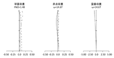
図2に当該光学系の無限遠合焦時の縦収差図をそれぞれ示す。それぞれの縦収差図は、図面に向かって左から順に、球面収差、非点収差、歪曲収差を表している。球面収差を表す図では、縦軸は開放F値との割合、横軸にデフォーカスをとり、実線がd線(波長λ=587.6nm)、破線がC線(波長λ=656.3nm)、一点鎖線がg線(波長λ=435.8nm)における球面収差を表す。非点収差を表す図では、縦軸は像高、横軸にデフォーカスをとり、実線がサジタル面、破線がメリジオナル面での非点収差を表す。歪曲収差を表す図では、縦軸は像高、横軸に%をとり、歪曲収差を表す。これらの縦収差図に関する事項は実施例2〜実施例4で示す各縦収差図においても同様であるため、以下では説明を省略する。 FIG. 2 shows longitudinal aberration diagrams of the optical system when focusing on infinity. Each longitudinal aberration diagram represents spherical aberration, astigmatism, and distortion aberration in order from the left toward the drawing. In the graph showing spherical aberration, the vertical axis is the ratio to the open F value, the horizontal axis is defocused, the solid line is the d line (wavelength λ = 587.6 nm), the broken line is the C line (wavelength λ = 656.3 nm), one point The chain line represents spherical aberration at the g-line (wavelength λ = 435.8 nm). In the diagram showing astigmatism, the vertical axis represents the image height, the horizontal axis defocused, the solid line represents the astigmatism on the sagittal surface, and the broken line represents the meridional surface. In the diagram showing distortion aberration, the vertical axis represents image height and the horizontal axis represents%, and represents distortion aberration. Since the matters relating to these longitudinal aberration diagrams are the same in the respective longitudinal aberration diagrams shown in Examples 2 to 4, description thereof will be omitted below.
また、当該光学系の焦点距離(f)、F値(Fno)、半画角(ω)は以下のとおりである。
f =82.500
Fno=1.829
ω =14.835
The focal length (f), F value (Fno), and half angle of view (ω) of the optical system are as follows.
f = 82.500
Fno = 1.829
ω = 14.835

(1)光学系の構成
図3は、本件発明に係る実施例2の光学系の無限遠合焦時におけるレンズ構成を示すレンズ断面図である。当該光学系は、物体側から順に、正の屈折力を有する第1レンズ群G1と、負の屈折力を有する第2レンズ群G2と、正の屈折力を有する第3レンズ群G3とから構成されている。
(1) Configuration of Optical System FIG. 3 is a lens cross-sectional view showing the lens configuration of the optical system of Example 2 according to the present invention when focusing on infinity. The optical system includes, in order from the object side, a first lens group G1 having a positive refractive power, a second lens group G2 having a negative refractive power, and a third lens group G3 having a positive refractive power. Has been.
第1レンズ群G1は、物体側から順に、正の屈折力を有するレンズL1と、正の屈折力を有するレンズL2と、負の屈折力を有するレンズL3及び正の屈折力を有する正レンズL4を接合した接合レンズと、から構成される。
第2レンズ群G2は、物体側から順に、物体側に凹面を向けた正の屈折力を有するレンズL5と、負の屈折力を有する両凹レンズL6とを接合した接合レンズにより構成される。
The first lens group G1 includes, in order from the object side, a lens L1 having a positive refractive power, a lens L2 having a positive refractive power, a lens L3 having a negative refractive power, and a positive lens L4 having a positive refractive power. And a cemented lens that is cemented.
The second lens group G2 includes, in order from the object side, a cemented lens in which a lens L5 having a positive refractive power with a concave surface facing the object side and a biconcave lens L6 having a negative refractive power are cemented.
第3レンズ群G3は、物体側から順に、正の屈折力を有する物体側群G3aと、開口絞りと、正の屈折力を有する像側群G3bと、から構成される。物体側群G3aは、物体側から順に、物体側に凸面を向けた正の屈折力を有するレンズL7と、正の屈折力を有するレンズL8と、負の屈折力を有する両凹レンズL9と、から構成される。像側群G3bは、物体側から順に、負の屈折力を有するレンズL10と、正の屈折力を有するレンズL11と、物体側に凹面を向けた負の屈折力を有するレンズL12及び正の屈折力を有するレンズL13を接合した接合レンズと、像側に凸面を向けた正の屈折力を有するレンズL14と、から構成される。 The third lens group G3 includes, in order from the object side, an object side group G3a having a positive refractive power, an aperture stop, and an image side group G3b having a positive refractive power. The object side group G3a includes, in order from the object side, a lens L7 having a positive refractive power with a convex surface facing the object side, a lens L8 having a positive refractive power, and a biconcave lens L9 having a negative refractive power. Composed. The image side group G3b includes, in order from the object side, a lens L10 having negative refractive power, a lens L11 having positive refractive power, a lens L12 having negative refractive power with a concave surface facing the object side, and positive refraction. The lens includes a cemented lens in which a lens L13 having power is cemented, and a lens L14 having a positive refractive power with a convex surface facing the image side.
当該実施例2の光学系において、無限遠物体から近距離物体への合焦の際、第1レンズ群G1と第3レンズ群G3が光軸方向に固定された状態で、第2レンズ群G2が光軸に沿って像面IMG側に移動する。また、手振れ等により撮像時に振動が発生した時には、防振群として、第3レンズ群G3の像側群G3b中のレンズL11を光軸と垂直な方向に動かすことで、像面IMG上の像のブレを補正する。なお、実施例1と同様に、このレンズL11以外のレンズを防振群としてもよいのは勿論である。 In the optical system of Example 2, when focusing from an object at infinity to an object at a short distance, the second lens group G2 with the first lens group G1 and the third lens group G3 fixed in the optical axis direction. Moves to the image plane IMG side along the optical axis. Further, when vibration occurs during imaging due to camera shake or the like, the image on the image plane IMG is moved by moving the lens L11 in the image side group G3b of the third lens group G3 in the direction perpendicular to the optical axis as a vibration proof group. Correct blurring. Of course, as in the first embodiment, lenses other than the lens L11 may be used as the image stabilizing group.
(2)数値実施例
次に、当該光学系の具体的数値を適用した数値実施例について説明する。表3は、当該光学系のレンズデータであり、表4は、表3に示した光軸上の可変間隔である。また、表9に条件式(1)〜条件式(10)の数値を示す。さらに、図4は、当該光学系の無限遠合焦時の縦収差図である。
(2) Numerical Examples Next, numerical examples to which specific numerical values of the optical system are applied will be described. Table 3 shows lens data of the optical system, and Table 4 shows variable intervals on the optical axis shown in Table 3. Table 9 shows numerical values of the conditional expressions (1) to (10). FIG. 4 is a longitudinal aberration diagram of the optical system at the time of focusing on infinity.
また、当該光学系の焦点距離(f)、F値(Fno)、半画角(ω)は以下のとおりである。
f =82.500
Fno=1.830
ω =14.835
The focal length (f), F value (Fno), and half angle of view (ω) of the optical system are as follows.
f = 82.500
Fno = 1.830
ω = 14.835
(1)光学系の構成
図5は、本件発明に係る実施例3の無限遠合焦時におけるレンズ構成を示すレンズ断面図である。当該光学系は、物体側から順に、正の屈折力を有する第1レンズ群G1と、負の屈折力を有する第2レンズ群G2と、正の屈折力を有する第3レンズ群G3と、から構成されている。
(1) Configuration of Optical System FIG. 5 is a lens cross-sectional view showing a lens configuration at the time of focusing on infinity according to Example 3 of the present invention. The optical system includes, in order from the object side, a first lens group G1 having a positive refractive power, a second lens group G2 having a negative refractive power, and a third lens group G3 having a positive refractive power. It is configured.
第1レンズ群G1は、物体側から順に、正の屈折力を有するレンズL1と、正の屈折力を有するレンズL2と、負の屈折力を有するレンズL3及び正の屈折力を有するレンズL4を接合した接合レンズと、から構成される。
第2レンズ群G2は、物体側から順に像面側に凸面を向けた正の屈折力を有するレンズL5と、負の屈折力を有する両凹レンズL6とを接合した接合レンズにより構成される。
The first lens group G1 includes, in order from the object side, a lens L1 having a positive refractive power, a lens L2 having a positive refractive power, a lens L3 having a negative refractive power, and a lens L4 having a positive refractive power. And a cemented cemented lens.
The second lens group G2 includes a cemented lens in which a lens L5 having a positive refractive power with a convex surface facing the image surface side in order from the object side and a biconcave lens L6 having a negative refractive power are cemented.
第3レンズ群G3は、物体側から順に、負の屈折力を有する物体側群G3aと、開口絞りと、正の屈折力を有する像側群G3bと、から構成される。物体側群G3aは、物体側から順に、物体側に凸面を向けた正の屈折力を有するレンズL7と負の屈折力を有する両凹レンズL8とを接合した接合レンズにより構成される。像側群G3bは、物体側から順に、正の屈折力を有するレンズL9と、負の屈折力を有する両凹レンズL10と、正の屈折力を有する両凸レンズL11及び負の屈折力を有する両凹レンズL12を接合した接合レンズと、像側に凸面を向けた正の屈折力を有するレンズL13と、から構成される。 The third lens group G3 includes, in order from the object side, an object side group G3a having a negative refractive power, an aperture stop, and an image side group G3b having a positive refractive power. The object side group G3a is composed of a cemented lens in which, in order from the object side, a lens L7 having a positive refractive power with a convex surface facing the object side and a biconcave lens L8 having a negative refractive power are cemented. The image side group G3b includes, in order from the object side, a lens L9 having a positive refractive power, a biconcave lens L10 having a negative refractive power, a biconvex lens L11 having a positive refractive power, and a biconcave lens having a negative refractive power. The lens includes a cemented lens in which L12 is cemented and a lens L13 having a positive refractive power with a convex surface facing the image side.
当該実施例3の光学系において、無限遠物体から近距離物体への合焦の際、第1レンズ群G1と第3レンズ群G3が光軸方向に固定された状態で、第2レンズ群G2が光軸に沿って像面IMG側に移動する。また、手振れ等により撮像時に振動が発生した時には、防振群として、第3レンズ群G3の像側群G3b中のレンズL13を光軸と垂直な方向に動かすことで、像面IMG上の像のブレを補正する。なお、実施例1と同様に、このレンズL13以外のレンズを防振群としてもよいのは勿論である。 In the optical system of the third embodiment, the second lens group G2 with the first lens group G1 and the third lens group G3 fixed in the optical axis direction at the time of focusing from an object at infinity to an object at a short distance. Moves to the image plane IMG side along the optical axis. Further, when vibration occurs during imaging due to camera shake or the like, the image on the image plane IMG is moved by moving the lens L13 in the image side group G3b of the third lens group G3 in the direction perpendicular to the optical axis as a vibration proof group. Correct blurring. Of course, as in the first embodiment, lenses other than the lens L13 may be used as the image stabilizing group.
(2)数値実施例
次に、当該光学系の具体的数値を適用した数値実施例について説明する。表5は、当該光学系のレンズデータであり、表6は、表5に示した光軸上の可変間隔である。また、表9に条件式(1)〜条件式(10)の数値を示す。さらに、図6は、当該光学系の無限遠合焦時の縦収差図である。
(2) Numerical Examples Next, numerical examples to which specific numerical values of the optical system are applied will be described. Table 5 shows lens data of the optical system, and Table 6 shows variable intervals on the optical axis shown in Table 5. Table 9 shows numerical values of the conditional expressions (1) to (10). FIG. 6 is a longitudinal aberration diagram when the optical system is focused on infinity.
また、当該光学系の焦点距離(f)、F値(Fno)、半画角(ω)は以下のとおりである。
f =113.000
Fno=1.456
ω =10.632
The focal length (f), F value (Fno), and half angle of view (ω) of the optical system are as follows.
f = 113.000
Fno = 1.456
ω = 10.632
(1)光学系の構成
図7は、本件発明に係る実施例4の光学系の無限遠合焦時におけるレンズ構成を示すレンズ断面図である。当該光学系は、物体側から順に、正の屈折力を有する第1レンズ群G1と、負の屈折力を有する第2レンズ群G2と、正の屈折力を有する第3レンズ群G3と、から構成されている。
(1) Configuration of Optical System FIG. 7 is a lens cross-sectional view showing the lens configuration of the optical system of Example 4 according to the present invention when focusing on infinity. The optical system includes, in order from the object side, a first lens group G1 having a positive refractive power, a second lens group G2 having a negative refractive power, and a third lens group G3 having a positive refractive power. It is configured.
第1レンズ群G1は、物体側から順に、正の屈折力を有するレンズL1と、正の屈折力を有するレンズL2及び負の屈折力を有するレンズL3を接合した接合レンズと、から構成される。
第2レンズ群G2は、物体側から順に、負の屈折力を有する両凹レンズL4と、像面側に凹面を向けた負の屈折力を有するレンズL5及び正の屈折力を有するレンズL6を接合した接合レンズと、から構成される。
The first lens group G1 includes, in order from the object side, a lens L1 having a positive refractive power, and a cemented lens obtained by cementing a lens L2 having a positive refractive power and a lens L3 having a negative refractive power. .
The second lens group G2 includes, in order from the object side, a biconcave lens L4 having negative refractive power, a lens L5 having negative refractive power with a concave surface facing the image plane side, and a lens L6 having positive refractive power. And a cemented lens.
第3レンズ群G3は、物体側から順に、負の屈折力を有する物体側群G3aと、開口絞りと、正の屈折力を有する像側群G3bと、から構成される。物体側群G3aは、物体側から順に、物体側に凸面を向けた正の屈折力を有するレンズL7と、負の屈折力を有する両凹レンズL8と、から構成される。像側群G3bは、物体側から順に、正の屈折力を有するレンズL9と、負の屈折力を有するレンズL10と、正の屈折力を有する両凸レンズL11及び負の屈折力を有する両凹レンズL12を接合した接合レンズと、像側に凸面を向けた正の屈折力を有するレンズL13と、から構成される。 The third lens group G3 includes, in order from the object side, an object side group G3a having a negative refractive power, an aperture stop, and an image side group G3b having a positive refractive power. The object side group G3a includes, in order from the object side, a lens L7 having a positive refractive power with a convex surface facing the object side, and a biconcave lens L8 having a negative refractive power. The image side group G3b includes, in order from the object side, a lens L9 having a positive refractive power, a lens L10 having a negative refractive power, a biconvex lens L11 having a positive refractive power, and a biconcave lens L12 having a negative refractive power. And a lens L13 having a positive refractive power with a convex surface facing the image side.
当該実施例4の光学系において、無限遠物体から近距離物体への合焦の際、第1レンズ群G1と第3レンズ群G3が光軸方向に固定された状態で、第2レンズ群G2が光軸に沿って像面IMG側に移動する。また、手振れ等により撮像時に振動が発生した時には、防振群として、第3レンズ群G3の像側群G3b中のレンズL10を光軸と垂直な方向に動かすことで、像面IMG上の像のブレを補正する。なお、実施例1と同様に、このレンズL10以外のレンズを防振群としてもよいのは勿論である。 In the optical system of the fourth embodiment, when focusing from an object at infinity to an object at a short distance, the second lens group G2 with the first lens group G1 and the third lens group G3 fixed in the optical axis direction. Moves to the image plane IMG side along the optical axis. Further, when vibration occurs during imaging due to camera shake or the like, the image on the image plane IMG is moved by moving the lens L10 in the image side group G3b of the third lens group G3 in the direction perpendicular to the optical axis as a vibration proof group. Correct blurring. Of course, as in the first embodiment, lenses other than the lens L10 may be used as the image stabilizing group.
(2)数値実施例
次に、当該光学系の具体的数値を適用した数値実施例について説明する。表7は、当該光学系のレンズデータであり、表8は、表7に示した光軸上の可変間隔である。また、表9に条件式(1)〜条件式(10)の数値を示す。さらに、図8は、当該光学系の無限遠合焦時の縦収差図である。
(2) Numerical Examples Next, numerical examples to which specific numerical values of the optical system are applied will be described. Table 7 shows lens data of the optical system, and Table 8 shows variable intervals on the optical axis shown in Table 7. Table 9 shows numerical values of the conditional expressions (1) to (10). Further, FIG. 8 is a longitudinal aberration diagram of the optical system when focused on infinity.
また、当該光学系の焦点距離(f)、F値(Fno)、半画角(ω)は以下のとおりである。
f =83.300
Fno=1.476
ω =14.665
The focal length (f), F value (Fno), and half angle of view (ω) of the optical system are as follows.
f = 83.300
Fno = 1.476
ω = 14.665
本件発明によれば、小型の撮像システムに好適な小型、高性能、且つ、大口径の光学系及び撮像装置を提供することができる。 According to the present invention, it is possible to provide a small-sized, high-performance, large-diameter optical system and an imaging apparatus suitable for a small-sized imaging system.
G1 ・・・第1レンズ群
G2 ・・・第2レンズ群
G3 ・・・第3レンズ群
G3a・・・物体側群
G3b・・・像側群
S ・・・開口絞り
CG ・・・カバーガラス
IMG・・・像面
G1 ... 1st lens group G2 ... 2nd lens group G3 ... 3rd lens group G3a ... Object side group G3b ... Image side group S ... Aperture stop CG ... Cover glass IMG: Image plane
Claims (10)
前記第1レンズ群と前記第3レンズ群とを光軸方向に固定し、前記第2レンズ群を光軸方向に移動させることで無限遠物体から有限距離物体への合焦を行い、
前記第3レンズ群が、物体側から順に、物体側群と、開口絞りと、像側群とから構成されており、
以下の条件を満足することを特徴とする光学系。
0.75 < f1/f < 1.30 ・・・(1)
0.722 ≦ f3/f < 1.10 ・・・(2a)
0 < Cr3af/f ・・・(5)
但し、
f1:前記第1レンズ群の焦点距離
f :当該光学系の焦点距離
f3:前記第3レンズ群の焦点距離
Cr3af:前記物体側群の最も物体側の面の曲率半径
である。 In order from the object side, the first lens group having a positive refractive power, a second lens group having a negative refractive power, and a third lens group having a positive refractive power,
The first lens group and the third lens group are fixed in the optical axis direction, and the second lens group is moved in the optical axis direction to perform focusing from an infinite object to a finite distance object,
The third lens group includes, in order from the object side, an object side group, an aperture stop, and an image side group.
An optical system characterized by satisfying the following conditions.
0.75 <f1 / f <1.30 (1)
0.722 ≦ f3 / f <1.10 (2a)
0 <Cr3af / f (5)
However,
f1: Focal length of the first lens group f: Focal length of the optical system f3: Focal length of the third lens group
Cr3af: the radius of curvature of the most object side surface of the object side group .
0.01 < f3b/f < 3.00 ・・・(3)
但し、
f3b:前記像側群の焦点距離
である。 The optical system according to claim 1, wherein the image side group satisfies the following condition.
0.01 <f3b / f <3.00 (3)
However,
f3b: focal length of the image side group.
0 < Cr3ar/f ・・・(4)
但し、
Cr3ar:前記物体側群の最も像面側の面の曲率半径
である。 The optical system according to claim 1, wherein a surface closest to the image plane of the object side group satisfies the following condition.
0 <Cr3ar / f (4)
However,
Cr3ar: the radius of curvature of the surface closest to the image plane in the object side group.
1.0 < Cr3af/Cr3ar < 4.0 ・・・(6)
但し、
Cr3ar:前記物体側群の最も像面側の面の曲率半径
である。 The optical system according to any one of claims 1 to 3 , wherein a most object-side surface of the object-side group and a most image-side surface of the object-side group satisfy the following conditions.
1.0 <Cr3af / Cr3ar <4.0 (6)
However ,
C r3ar: the radius of curvature of the surface closest to the image plane in the object side group.
0.30 < |f2|/f < 1.20 ・・・(7)
但し、
f2:前記第2レンズ群の焦点距離
である。 The optical system according to any one of claims 1 to 4 , wherein the second lens group satisfies the following conditions.
0.30 <| f2 | / f <1.20 (7)
However,
f2: focal length of the second lens group.
2.0 < f3/(f×tanω) < 5.0 ・・・(8)
但し、
ω :当該光学系の無限遠合焦時おける半画角
である。 The optical system according to any one of claims 1 to 7 , wherein the third lens group satisfies the following condition.
2.0 <f3 / (f × tan ω) <5.0 (8)
However ,
ω : Half angle of view of the optical system when focusing on infinity.
1.0 < |f3a|/f3b ・・・(9)
但し、
f3a : 前記物体側群の焦点距離
f3b : 前記像側群の焦点距離
である。 The optical system according to any one of claims 1 to 8 , wherein the object side group and the image side group satisfy the following conditions.
1.0 <| f3a | / f3b (9)
However,
f3a: focal length of the object side group
f3b: the focal length of the image side group .
Priority Applications (1)
| Application Number | Priority Date | Filing Date | Title |
|---|---|---|---|
| JP2015028902A JP6584085B2 (en) | 2015-02-17 | 2015-02-17 | Optical system and imaging apparatus |
Applications Claiming Priority (1)
| Application Number | Priority Date | Filing Date | Title |
|---|---|---|---|
| JP2015028902A JP6584085B2 (en) | 2015-02-17 | 2015-02-17 | Optical system and imaging apparatus |
Publications (3)
| Publication Number | Publication Date |
|---|---|
| JP2016151661A JP2016151661A (en) | 2016-08-22 |
| JP2016151661A5 JP2016151661A5 (en) | 2018-02-08 |
| JP6584085B2 true JP6584085B2 (en) | 2019-10-02 |
Family
ID=56696431
Family Applications (1)
| Application Number | Title | Priority Date | Filing Date |
|---|---|---|---|
| JP2015028902A Active JP6584085B2 (en) | 2015-02-17 | 2015-02-17 | Optical system and imaging apparatus |
Country Status (1)
| Country | Link |
|---|---|
| JP (1) | JP6584085B2 (en) |
Families Citing this family (3)
| Publication number | Priority date | Publication date | Assignee | Title |
|---|---|---|---|---|
| CN106680981B (en) * | 2016-11-20 | 2019-01-08 | 中国航空工业集团公司洛阳电光设备研究所 | A kind of more visual field optical systems of broadband |
| JP7172776B2 (en) | 2019-03-19 | 2022-11-16 | 株式会社リコー | shooting lens system |
| CN111820864B (en) * | 2020-07-31 | 2023-08-18 | 嘉兴中润光学科技股份有限公司 | Fundus imaging system |
Family Cites Families (8)
| Publication number | Priority date | Publication date | Assignee | Title |
|---|---|---|---|---|
| JP3486541B2 (en) * | 1997-10-16 | 2004-01-13 | キヤノン株式会社 | Inner focus optical system having vibration proof function and camera having the same |
| JP3445554B2 (en) * | 1999-04-02 | 2003-09-08 | ペンタックス株式会社 | Inner focus telephoto lens |
| JP5582905B2 (en) * | 2010-07-27 | 2014-09-03 | オリンパスイメージング株式会社 | Imaging optical system and imaging apparatus using the same |
| JP5664469B2 (en) * | 2011-06-14 | 2015-02-04 | コニカミノルタ株式会社 | Large-aperture variable magnification optical system and imaging device |
| KR20130069046A (en) * | 2011-12-16 | 2013-06-26 | 삼성전자주식회사 | Telephoto lens system |
| JP5968121B2 (en) * | 2012-06-29 | 2016-08-10 | キヤノン株式会社 | Optical system and imaging apparatus having the same |
| JP6099966B2 (en) * | 2012-12-21 | 2017-03-22 | キヤノン株式会社 | Imaging optical system and imaging apparatus having the same |
| JP6210208B2 (en) * | 2012-12-27 | 2017-10-11 | パナソニックIpマネジメント株式会社 | Inner focus lens system, interchangeable lens device and camera system |
-
2015
- 2015-02-17 JP JP2015028902A patent/JP6584085B2/en active Active
Also Published As
| Publication number | Publication date |
|---|---|
| JP2016151661A (en) | 2016-08-22 |
Similar Documents
| Publication | Publication Date | Title |
|---|---|---|
| JP6462415B2 (en) | Optical system and imaging apparatus | |
| JP6356622B2 (en) | Zoom lens and imaging device | |
| JP2016161650A5 (en) | ||
| JP6401420B2 (en) | Zoom lens and imaging device | |
| JP6689768B2 (en) | Imaging lens and imaging device | |
| JP6219183B2 (en) | Imaging lens and imaging apparatus | |
| JP6331673B2 (en) | Optical system, optical device | |
| JP6584085B2 (en) | Optical system and imaging apparatus | |
| JP2017097197A (en) | Wide angle lens and imaging apparatus | |
| JP6584086B2 (en) | Optical system and imaging apparatus | |
| JP6609412B2 (en) | Optical system and imaging apparatus | |
| JP6563200B2 (en) | Zoom lens and imaging device | |
| JP6320904B2 (en) | Imaging lens and imaging apparatus | |
| JP6518067B2 (en) | Optical system and imaging device | |
| JP2018072457A (en) | Optical system and image capturing device | |
| JP2017116763A (en) | Optical and imaging apparatus | |
| JP6546752B2 (en) | Optical system and imaging device | |
| JP6603459B2 (en) | Optical system and imaging apparatus | |
| JP6563216B2 (en) | Optical system and imaging apparatus | |
| JP2016151665A (en) | Optical system and imaging apparatus | |
| JP6670690B2 (en) | Optical system and imaging device | |
| JP2017097198A (en) | Wide angle lens and imaging apparatus | |
| JP2016126275A (en) | Optical system and image capturing device | |
| JP6492416B2 (en) | Optical system, optical device | |
| JP2016126276A (en) | Optical system and image capturing device |
Legal Events
| Date | Code | Title | Description |
|---|---|---|---|
| A521 | Request for written amendment filed |
Free format text: JAPANESE INTERMEDIATE CODE: A523 Effective date: 20171220 |
|
| A621 | Written request for application examination |
Free format text: JAPANESE INTERMEDIATE CODE: A621 Effective date: 20171226 |
|
| A977 | Report on retrieval |
Free format text: JAPANESE INTERMEDIATE CODE: A971007 Effective date: 20181130 |
|
| A131 | Notification of reasons for refusal |
Free format text: JAPANESE INTERMEDIATE CODE: A131 Effective date: 20181214 |
|
| A601 | Written request for extension of time |
Free format text: JAPANESE INTERMEDIATE CODE: A601 Effective date: 20190118 |
|
| A521 | Request for written amendment filed |
Free format text: JAPANESE INTERMEDIATE CODE: A523 Effective date: 20190326 |
|
| TRDD | Decision of grant or rejection written | ||
| A01 | Written decision to grant a patent or to grant a registration (utility model) |
Free format text: JAPANESE INTERMEDIATE CODE: A01 Effective date: 20190806 |
|
| A61 | First payment of annual fees (during grant procedure) |
Free format text: JAPANESE INTERMEDIATE CODE: A61 Effective date: 20190903 |
|
| R150 | Certificate of patent or registration of utility model |
Ref document number: 6584085 Country of ref document: JP Free format text: JAPANESE INTERMEDIATE CODE: R150 |
|
| R250 | Receipt of annual fees |
Free format text: JAPANESE INTERMEDIATE CODE: R250 |
|
| R250 | Receipt of annual fees |
Free format text: JAPANESE INTERMEDIATE CODE: R250 |