JP6568143B2 - Medical monitoring system - Google Patents
Medical monitoring system Download PDFInfo
- Publication number
- JP6568143B2 JP6568143B2 JP2017093861A JP2017093861A JP6568143B2 JP 6568143 B2 JP6568143 B2 JP 6568143B2 JP 2017093861 A JP2017093861 A JP 2017093861A JP 2017093861 A JP2017093861 A JP 2017093861A JP 6568143 B2 JP6568143 B2 JP 6568143B2
- Authority
- JP
- Japan
- Prior art keywords
- patient
- clinician
- medical
- module
- patient monitoring
- Prior art date
- Legal status (The legal status is an assumption and is not a legal conclusion. Google has not performed a legal analysis and makes no representation as to the accuracy of the status listed.)
- Active
Links
Images


Classifications
-
- G—PHYSICS
- G16—INFORMATION AND COMMUNICATION TECHNOLOGY [ICT] SPECIALLY ADAPTED FOR SPECIFIC APPLICATION FIELDS
- G16H—HEALTHCARE INFORMATICS, i.e. INFORMATION AND COMMUNICATION TECHNOLOGY [ICT] SPECIALLY ADAPTED FOR THE HANDLING OR PROCESSING OF MEDICAL OR HEALTHCARE DATA
- G16H40/00—ICT specially adapted for the management or administration of healthcare resources or facilities; ICT specially adapted for the management or operation of medical equipment or devices
- G16H40/40—ICT specially adapted for the management or administration of healthcare resources or facilities; ICT specially adapted for the management or operation of medical equipment or devices for the management of medical equipment or devices, e.g. scheduling maintenance or upgrades
-
- G—PHYSICS
- G06—COMPUTING; CALCULATING OR COUNTING
- G06F—ELECTRIC DIGITAL DATA PROCESSING
- G06F3/00—Input arrangements for transferring data to be processed into a form capable of being handled by the computer; Output arrangements for transferring data from processing unit to output unit, e.g. interface arrangements
- G06F3/01—Input arrangements or combined input and output arrangements for interaction between user and computer
- G06F3/048—Interaction techniques based on graphical user interfaces [GUI]
- G06F3/0481—Interaction techniques based on graphical user interfaces [GUI] based on specific properties of the displayed interaction object or a metaphor-based environment, e.g. interaction with desktop elements like windows or icons, or assisted by a cursor's changing behaviour or appearance
- G06F3/0482—Interaction with lists of selectable items, e.g. menus
-
- G—PHYSICS
- G16—INFORMATION AND COMMUNICATION TECHNOLOGY [ICT] SPECIALLY ADAPTED FOR SPECIFIC APPLICATION FIELDS
- G16H—HEALTHCARE INFORMATICS, i.e. INFORMATION AND COMMUNICATION TECHNOLOGY [ICT] SPECIALLY ADAPTED FOR THE HANDLING OR PROCESSING OF MEDICAL OR HEALTHCARE DATA
- G16H10/00—ICT specially adapted for the handling or processing of patient-related medical or healthcare data
- G16H10/60—ICT specially adapted for the handling or processing of patient-related medical or healthcare data for patient-specific data, e.g. for electronic patient records
-
- G—PHYSICS
- G16—INFORMATION AND COMMUNICATION TECHNOLOGY [ICT] SPECIALLY ADAPTED FOR SPECIFIC APPLICATION FIELDS
- G16H—HEALTHCARE INFORMATICS, i.e. INFORMATION AND COMMUNICATION TECHNOLOGY [ICT] SPECIALLY ADAPTED FOR THE HANDLING OR PROCESSING OF MEDICAL OR HEALTHCARE DATA
- G16H30/00—ICT specially adapted for the handling or processing of medical images
- G16H30/20—ICT specially adapted for the handling or processing of medical images for handling medical images, e.g. DICOM, HL7 or PACS
-
- G—PHYSICS
- G16—INFORMATION AND COMMUNICATION TECHNOLOGY [ICT] SPECIALLY ADAPTED FOR SPECIFIC APPLICATION FIELDS
- G16H—HEALTHCARE INFORMATICS, i.e. INFORMATION AND COMMUNICATION TECHNOLOGY [ICT] SPECIALLY ADAPTED FOR THE HANDLING OR PROCESSING OF MEDICAL OR HEALTHCARE DATA
- G16H40/00—ICT specially adapted for the management or administration of healthcare resources or facilities; ICT specially adapted for the management or operation of medical equipment or devices
- G16H40/20—ICT specially adapted for the management or administration of healthcare resources or facilities; ICT specially adapted for the management or operation of medical equipment or devices for the management or administration of healthcare resources or facilities, e.g. managing hospital staff or surgery rooms
-
- G—PHYSICS
- G16—INFORMATION AND COMMUNICATION TECHNOLOGY [ICT] SPECIALLY ADAPTED FOR SPECIFIC APPLICATION FIELDS
- G16H—HEALTHCARE INFORMATICS, i.e. INFORMATION AND COMMUNICATION TECHNOLOGY [ICT] SPECIALLY ADAPTED FOR THE HANDLING OR PROCESSING OF MEDICAL OR HEALTHCARE DATA
- G16H40/00—ICT specially adapted for the management or administration of healthcare resources or facilities; ICT specially adapted for the management or operation of medical equipment or devices
- G16H40/60—ICT specially adapted for the management or administration of healthcare resources or facilities; ICT specially adapted for the management or operation of medical equipment or devices for the operation of medical equipment or devices
- G16H40/63—ICT specially adapted for the management or administration of healthcare resources or facilities; ICT specially adapted for the management or operation of medical equipment or devices for the operation of medical equipment or devices for local operation
-
- G—PHYSICS
- G16—INFORMATION AND COMMUNICATION TECHNOLOGY [ICT] SPECIALLY ADAPTED FOR SPECIFIC APPLICATION FIELDS
- G16H—HEALTHCARE INFORMATICS, i.e. INFORMATION AND COMMUNICATION TECHNOLOGY [ICT] SPECIALLY ADAPTED FOR THE HANDLING OR PROCESSING OF MEDICAL OR HEALTHCARE DATA
- G16H40/00—ICT specially adapted for the management or administration of healthcare resources or facilities; ICT specially adapted for the management or operation of medical equipment or devices
- G16H40/60—ICT specially adapted for the management or administration of healthcare resources or facilities; ICT specially adapted for the management or operation of medical equipment or devices for the operation of medical equipment or devices
- G16H40/67—ICT specially adapted for the management or administration of healthcare resources or facilities; ICT specially adapted for the management or operation of medical equipment or devices for the operation of medical equipment or devices for remote operation
-
- G—PHYSICS
- G16—INFORMATION AND COMMUNICATION TECHNOLOGY [ICT] SPECIALLY ADAPTED FOR SPECIFIC APPLICATION FIELDS
- G16H—HEALTHCARE INFORMATICS, i.e. INFORMATION AND COMMUNICATION TECHNOLOGY [ICT] SPECIALLY ADAPTED FOR THE HANDLING OR PROCESSING OF MEDICAL OR HEALTHCARE DATA
- G16H50/00—ICT specially adapted for medical diagnosis, medical simulation or medical data mining; ICT specially adapted for detecting, monitoring or modelling epidemics or pandemics
- G16H50/50—ICT specially adapted for medical diagnosis, medical simulation or medical data mining; ICT specially adapted for detecting, monitoring or modelling epidemics or pandemics for simulation or modelling of medical disorders
Description
関連出願の相互参照
本出願は、参照によりそれぞれの全内容が本明細書に組み込まれている、2009年3
月4日に出願された米国特許仮出願第61/209147号(件名「PROXIMITY
DISPLAY MONITOR」)、ならびに2010年1月19日に出願された米
国特許仮出願第61/296439号(件名「MEDICAL MONITORING
SYSTEM」)の優先権の利益を主張するものである。
CROSS REFERENCE TO RELATED APPLICATIONS This application is herein incorporated by reference in its entirety, each of which is incorporated herein by reference.
US Provisional Patent Application No. 61/209147 (subject name “PROXIMITY”)
DISPLAY MONITOR "), and US Provisional Application No. 61 / 296,439 filed on January 19, 2010 (subject" MEDICAL MONITORING ").
System ") priority interests.
本開示は、たとえば、病院および他の患者治療施設における用途を有するシステム、装
置、および方法に関する。たとえば、本明細書に記載のシステム、装置、および方法は、
患者からの生理学的情報の取得、その生理学的情報の分析、およびその生理学的情報の、
臨床担当者および他のシステムまたは装置への伝達に使用可能である。
The present disclosure relates to systems, devices, and methods having applications in, for example, hospitals and other patient care facilities. For example, the systems, devices, and methods described herein are:
Obtaining physiological information from the patient, analyzing the physiological information, and analyzing the physiological information,
Can be used to communicate to clinicians and other systems or devices.
病院、介護施設、および他の患者治療施設は、典型的には、施設内の1つ以上のベッド
サイドに患者監視装置を備えている。患者監視装置は、一般に、医療患者の生理学的パラ
メータを取得および分析するためのセンサ、処理装置、およびディスプレイを備えている
。生理学的パラメータにはいろいろなものがあるが、たとえば、呼吸数、SpO2レベル
、脈拍、血圧などが挙げられる。医師、看護師、および他の特定の医療従事者を含む臨床
担当者は、医療患者から取得された生理学的パラメータを用いて、病気の診断および治療
の処方を行う。また、臨床担当者は、生理学的パラメータを用いて、様々な臨床的状況に
ある患者を監視して、患者に対する治療のレベルを上げるかどうかを決定する。
Hospitals, care facilities, and other patient care facilities typically include patient monitoring devices at one or more bedsides within the facility. Patient monitoring devices generally include sensors, processing devices, and displays for acquiring and analyzing physiological parameters of a medical patient. There are various physiological parameters, such as respiratory rate, SpO 2 level, pulse rate, blood pressure, and the like. Clinical personnel, including doctors, nurses, and other specific health professionals, use physiological parameters obtained from medical patients to diagnose the disease and prescribe treatment. The clinician also uses physiological parameters to monitor patients in various clinical situations to determine whether to increase the level of treatment for the patient.
HbCO、HbMet、総ヘモグロビン(Hbt)などのような詳細なパラメータに加
えてSpO2や脈拍数のようなパルスオキシメトリパラメータを測定できる患者監視器、
ならびに対応する複数の波長光学センサについての説明が、少なくとも、2006年3月
1日に出願された米国特許出願第11/367013号明細書(件名「Multiple
Wavelength Sensor Emitters」)、ならびに2006年3
月1日に出願された米国特許出願第11/366208号明細書(件名「Noninva
sive Multi−Parameter Patient Monitor」)にお
いてなされており、これらは両方ともMasimo Laboratories,Irv
ine,CA(Masimo Labs)に譲渡されており、両方とも、参照により本明
細書に組み込まれている。さらに、いろいろなパラメータの中でも特にSpO2、脈拍数
、灌流指数、信号品質、HbCO、およびHbMetを測定するための非侵襲的血液パラ
メータ監視器および対応する複数の波長光学センサ(Rainbow(商標)粘着式再利
用可能センサやRAD−57(商標)およびRadical−7(商標)監視器など)が
、Masimo Corporation,Irvine,CA(Masimo)から入
手可能である。
A patient monitor that can measure pulse oximetry parameters such as SpO 2 and pulse rate in addition to detailed parameters such as HbCO, HbMet, total hemoglobin (Hbt), etc.
As well as a description of a corresponding plurality of wavelength optical sensors, at least in US patent application Ser. No. 11 / 367,003 filed Mar. 1, 2006 (subject “Multiple”).
Wavelength Sensor Emitters ”), and March 2006
No. 11/366208 filed on Jan. 1 (subject “Noninva”)
"Seven Multi-Parameter Peptide Monitor"), both of which are Masimo Laboratories, Irv.
ine, CA (Masimo Labs), both of which are incorporated herein by reference. Furthermore, a non-invasive blood parameter monitor and corresponding multi-wavelength optical sensor (Rainbow ™ adhesion) for measuring SpO 2 , pulse rate, perfusion index, signal quality, HbCO, and HbMet, among other parameters Reusable sensors such as RAD-57 ™ and Radical-7 ™ monitors) are available from Masimo Corporation, Irvine, CA (Masimo).
高度な生理学的監視システムは、たとえば、ほんの数例であるが、一酸化炭素ヘモグロ
ビン(HbCO)、メトヘモグロビン(HbMet)、および総ヘモグロビン(Hbt)
などのような他の血液パラメータの計算および表示のための詳細機能に加えて、パルスオ
キシメトリを組み込むことが可能である。SpO2に加えて、HbCO、HbMet、H
btなどのパラメータを測定できる、高度な生理学的監視器および対応する複数の波長光
学センサについての説明が、少なくとも、2006年3月1日に出願された米国特許出願
第11/367013号明細書(件名「Multiple Wavelength Se
nsor Emitters」)、ならびに2006年3月1日に出願された米国特許出
願第11/366208号明細書(件名「Noninvasive Multi−Par
ameter Patient Monitor」)においてなされており、これらはM
asimo Labsに譲渡されており、参照により本明細書に組み込まれている。さら
に、いろいろなパラメータの中でも特にSpO2、脈拍数、灌流指数(PI)、信号品質
(SiQ)、拍動変動指数(PVI)、HbCO、およびHbMetを測定するための非
侵襲的血液パラメータ監視器および対応する複数の波長光学センサ(Rainbow(商
標)粘着式再利用可能センサやRAD−57(商標)およびRadical−7(商標)
監視器など)が、Masimoから入手可能である。
Advanced physiological monitoring systems are, for example, only a few examples: carbon monoxide hemoglobin (HbCO), methemoglobin (HbMet), and total hemoglobin (Hbt).
In addition to detailed functions for the calculation and display of other blood parameters such as, pulse oximetry can be incorporated. In addition to SpO 2, HbCO, HbMet, H
A description of an advanced physiological monitor and corresponding multi-wavelength optical sensor capable of measuring parameters such as bt is at least described in US patent application Ser. No. 11 / 367,003 filed Mar. 1, 2006. Subject “Multiple Wavelength Se”
nsor Emitters "), as well as US patent application Ser. No. 11 / 366,208, filed Mar. 1, 2006 (subject“ Noninvasive Multi-Par ”).
AMTERITE PATIENT MONITOR "), these are M
assigned to Asimo Labs and incorporated herein by reference. In addition, a noninvasive blood parameter monitor for measuring SpO 2 , pulse rate, perfusion index (PI), signal quality (SiQ), pulsation variability index (PVI), HbCO, and HbMet, among other parameters. And corresponding multiple wavelength optical sensors (Rainbow ™ adhesive reusable sensors, RAD-57 ™ and Radical-7 ™)
Monitors, etc.) are available from Masimo.
本明細書には、様々な医療監視装置、システム、および方法を記載している。 Various medical monitoring devices, systems, and methods are described herein.
実施形態によっては、医療監視装置またはシステムが、臨床担当者の存在を検知するこ
と、ならびに、たとえば、臨床担当者の存在が検知されたことに対する応答として何らか
のアクションを実行することが可能である。実施形態によっては、医療監視システムは、
病院または他の患者治療施設において、いくつかの医療装置、何人かの臨床担当者、およ
び/または何人かの患者の位置を検出することが可能である。そして、検出された位置を
用いて、位置に基づく何らかのアクション、たとえば、医療装置の構成変更などを行うこ
とが可能である。
In some embodiments, a medical monitoring device or system can detect the presence of a clinician and perform some action in response to, for example, detecting the presence of a clinician. In some embodiments, the medical monitoring system is
It is possible to detect the location of several medical devices, some clinicians, and / or some patients in a hospital or other patient treatment facility. Then, using the detected position, it is possible to perform some action based on the position, for example, change the configuration of the medical device.
本明細書では、医療通信プロトコル変換器を用いて医療監視装置(またはシステム)間
の通信を促進する様々な装置、システム、および方法を記載する。異なるプロトコルフォ
ーマットで通信するようにプログラムされている医療装置間の通信を促進するために、医
療通信プロトコル変換器を構成することが可能である。医療通信プロトコル変換器は、第
1のプロトコルフォーマットに従ってフォーマットされた入力メッセージを第1の医療装
置から受信すること、ならびに、変換ルールセットを用いて、第2の医療装置によってサ
ポートされている第2のプロトコルフォーマットに従ってフォーマットされた出力メッセ
ージを出力することが可能である。たとえば、医療通信プロトコル変換器は、第1のHL
7プロトコルフォーマットに従ってフォーマットされた入力メッセージを病院情報システ
ムから受信すること、ならびに、変換ルールセットとの比較に基づいて、第2のHL7プ
ロトコルフォーマットに従ってフォーマットされた出力メッセージを出力することが可能
である。
Described herein are various devices, systems, and methods that facilitate communication between medical monitoring devices (or systems) using medical communication protocol converters. A medical communication protocol converter can be configured to facilitate communication between medical devices that are programmed to communicate in different protocol formats. The medical communication protocol converter receives an input message formatted according to the first protocol format from the first medical device and uses a conversion rule set to support a second supported by the second medical device. It is possible to output an output message formatted according to the protocol format. For example, the medical communication protocol converter has a first HL
It is possible to receive an input message formatted according to the 7 protocol format from the hospital information system and output an output message formatted according to the second HL7 protocol format based on comparison with the transformation rule set. .
実施形態によっては、医療監視装置またはシステムが、何人かの患者から生理学的パラ
メータデータを収集すること、ならびに、このデータを用いて様々なアラーム状態検出条
件および/またはアラーム通知遅延時間をシミュレートすることが可能である。これらの
シミュレートされたアラーム状態検出条件および/またはアラーム通知遅延時間を解析お
よび使用することにより、(たとえば、ベッドサイド患者監視装置で使用される)実際の
アラーム状態検出条件および/またはアラーム通知遅延時間を変更することが可能である
。
In some embodiments, a medical monitoring device or system collects physiological parameter data from several patients and uses this data to simulate various alarm condition detection conditions and / or alarm notification delay times It is possible. By analyzing and using these simulated alarm condition detection conditions and / or alarm notification delay times, actual alarm condition detection conditions and / or alarm notification delays (eg, used in bedside patient monitoring devices) It is possible to change the time.
特定実施形態では、生理学的情報を監視する医療患者監視装置が、少なくとも1人の患
者から生理学的情報を受信するように構成されたインタフェースを備える。本装置はさら
に、生理学的情報に基づく臨床的に有用なタスクを実行するように構成されたプロセッサ
を備えることが可能である。本装置はまた、医療患者監視装置の近傍の検出範囲内におい
て、臨床担当者が誰であるかを表す臨床担当者トークンの物理的存在を検出する検出器を
備えることが可能である。さらに、本プロセッサは、臨床担当者トークンが検出されたこ
とに対する応答として、第1の所定のアクションを実行するように構成可能であり、第1
の所定のアクションは、臨床担当者が誰かという情報に関連付けられている。
In certain embodiments, a medical patient monitoring device that monitors physiological information comprises an interface configured to receive physiological information from at least one patient. The apparatus can further comprise a processor configured to perform clinically useful tasks based on physiological information. The device may also include a detector that detects the physical presence of a clinician token that represents who the clinician is within a detection range in the vicinity of the medical patient monitoring device. Further, the processor can be configured to perform a first predetermined action in response to detecting a clinician token,
The predetermined action is associated with information indicating who the clinical person is.
特定実施形態では、複数の医療装置の物理的位置を特定する臨床システムが、複数の患
者から生理学的情報を収集することが可能な複数の医療患者監視装置を備える。本臨床シ
ステムはさらに、医療患者監視装置からの無線信号を検出することが可能な検出器の分散
ネットワークを備えることが可能である。本臨床システムはまた、検出器から検出された
無線信号に基づいて、医療患者監視装置の物理的位置を推定することが可能な、検出器と
通信可能に結合された位置監視サーバを備えることが可能である。
In a particular embodiment, a clinical system that identifies the physical location of a plurality of medical devices comprises a plurality of medical patient monitoring devices capable of collecting physiological information from a plurality of patients. The clinical system may further comprise a distributed network of detectors capable of detecting wireless signals from medical patient monitoring devices. The clinical system also includes a position monitoring server communicatively coupled to the detector that is capable of estimating the physical position of the medical patient monitoring device based on the wireless signal detected from the detector. Is possible.
様々な実施形態において、医療情報ネットワーク内での第1および第2の医療装置の間
の通信を促進する方法が、第1の通信プロトコルに従って生成された第1の入力メッセー
ジを第1の医療装置から受信するステップを含む。入力メッセージは、第2の医療装置を
、入力メッセージの意図された受信側として識別することが可能である。本方法はさらに
、1つ以上の変換ルールを適用して入力メッセージを出力メッセージに変換するステップ
を含むことが可能である。本方法はまた、出力メッセージを第2の医療装置に与えるステ
ップを含むことが可能であり、第2の医療装置は、出力メッセージを受信して処理するよ
うに構成されている。
In various embodiments, a method for facilitating communication between a first and second medical device within a medical information network uses a first input message generated according to a first communication protocol as a first medical device. Receiving from. The input message may identify the second medical device as the intended recipient of the input message. The method may further include applying one or more conversion rules to convert the input message to an output message. The method can also include providing an output message to a second medical device, the second medical device being configured to receive and process the output message.
特定実施形態では、医療情報ネットワーク内での第1および第2の医療装置の間の通信
を促進するように構成された医療装置メッセージ変換器が、第1の通信プロトコルに従っ
て第1の入力メッセージを生成した第1の医療装置から第1の入力メッセージを受信する
ように構成された通信インタフェースモジュールを備える。入力メッセージは、第2の医
療装置を、入力メッセージの意図された受信側として識別することが可能である。変換器
はさらに、1つ以上の所定の変換ルールを格納するように構成されたルールモジュールと
、ルールモジュールから取り出した1つ以上の変換ルールを適用して入力メッセージを出
力メッセージに変換するように構成された変換モジュールとを備えることが可能である。
第2の医療装置は、出力メッセージを受信して処理するように構成可能である。
In a particular embodiment, a medical device message converter configured to facilitate communication between a first and second medical device within a medical information network receives a first input message according to a first communication protocol. A communication interface module configured to receive a first input message from the generated first medical device. The input message may identify the second medical device as the intended recipient of the input message. The converter further applies a rule module configured to store one or more predetermined conversion rules and one or more conversion rules retrieved from the rule module to convert the input message into an output message. It is possible to provide a configured conversion module.
The second medical device can be configured to receive and process the output message.
様々な実施形態において、複数の医療装置と病院情報システムまたは臨床情報システム
との間で伝達されるメッセージを変換する方法が、電子患者医療記録を備える病院情報シ
ステムから入力メッセージを受信するステップを含み、入力メッセージの内容は、医療電
子通信プロトコルで許可されている第1のフォーマッティングルールセットに従ってフォ
ーマットされている。本方法はさらに、入力メッセージを変換ルールセットと比較するス
テップと、出力メッセージを生成するステップとを含むことが可能であり、出力メッセー
ジの内容は、医療電子通信プロトコルで許可されている第2のフォーマッティングルール
セットに従って再フォーマットされている。変換ルールは、出力メッセージの内容の再フ
ォーマッティングを、第2のフォーマッティングルールセットに準拠するように制御する
ことが可能である。本方法はまた、出力メッセージを医療装置に出力するステップを含む
ことが可能である。
In various embodiments, a method for converting a message communicated between a plurality of medical devices and a hospital information system or a clinical information system includes receiving an input message from a hospital information system comprising an electronic patient medical record. The content of the input message is formatted according to a first formatting rule set permitted by the medical electronic communication protocol. The method may further include the step of comparing the input message with a transformation rule set and generating an output message, the content of the output message being a second permitted by the medical electronic communication protocol. Reformatted according to formatting rule set. The transformation rule can control the reformatting of the content of the output message to comply with the second formatting rule set. The method can also include outputting an output message to the medical device.
様々な実施形態において、共通の医療電子通信プロトコルに属するがフォーマットが異
なる入力医療メッセージおよび出力医療メッセージに対して、現場でのカスタマイズが可
能な変換を行う方法が、第1の医療装置から入力メッセージを受信するステップを含み、
入力メッセージの内容は、第1のフォーマッティングルールセットに従ってフォーマット
されている。本方法はさらに、入力メッセージから、意図された受信側医療装置を特定す
るステップを含むことが可能である。本方法はまた、入力メッセージを変換ルールセット
と比較するステップと、入力メッセージと変換ルールセットとの比較に基づいて、意図さ
れた受信側医療装置によって予期される第2のフォーマッティングルールセットを反映す
るように入力メッセージのフォーマッティングを変更するステップと、を含むことが可能
である。さらに、本方法はまた、内容が第2のフォーマッティングルールセットに従って
フォーマットされている出力メッセージを生成するステップと、出力メッセージを、意図
された受信側医療装置に出力するステップと、を含むことが可能である。
In various embodiments, a method for performing on-site customizable conversion for input medical messages and output medical messages belonging to a common medical electronic communication protocol but having different formats is provided from the first medical device. Including the step of receiving
The content of the input message is formatted according to the first formatting rule set. The method may further include identifying the intended recipient medical device from the input message. The method also reflects a second formatting rule set expected by the intended recipient medical device based on comparing the input message to the conversion rule set and comparing the input message to the conversion rule set. Changing the formatting of the input message as follows. Further, the method can also include generating an output message whose contents are formatted according to the second formatting rule set, and outputting the output message to the intended recipient medical device. It is.
特定実施形態では、病院情報システムと患者監視器との間の医療メッセージの伝達を促
進するシステムが、複数の患者の電子医療記録を格納するように構成された電子医療記録
データベースを有する病院情報システムを備える。本システムはさらに、患者の少なくと
も1つの生理学的状態を監視するように構成された患者監視器を備えることが可能である
。本システムはまた、病院情報システムと患者監視器との間に通信可能に結合されるよう
に構成された変換モジュールを備えることも可能である。変換モジュールは、内容が第1
のフォーマッティングルールセットに従ってフォーマットされている入力メッセージを病
院情報システムまたは患者監視器のうちの一方から受信するステップと、入力メッセージ
を変換ルールセットと比較するステップと、出力メッセージを生成するステップであって
、出力メッセージの内容は、第2のフォーマッティングルールセットに従って再フォーマ
ットされており、変換ルールは、出力メッセージの内容の再フォーマッティングを、第2
のフォーマッティングルールセットに準拠するように制御する、出力メッセージを生成す
るステップと、を行うように構成可能である。
In a particular embodiment, a system for facilitating communication of medical messages between a hospital information system and a patient monitor comprises a hospital information system having an electronic medical records database configured to store electronic medical records for a plurality of patients Is provided. The system can further comprise a patient monitor configured to monitor at least one physiological condition of the patient. The system may also include a conversion module configured to be communicatively coupled between the hospital information system and the patient monitor. The conversion module is the first
Receiving an input message formatted in accordance with a formatting rule set from one of a hospital information system or a patient monitor, comparing the input message with a transformation rule set, and generating an output message. The content of the output message has been reformatted according to the second formatting rule set, and the transformation rule has to reformat the content of the output message
Generating an output message that is controlled to comply with the formatting rule set of
特定実施形態では、ネットワーク経由での医療装置間の医療メッセージの伝達を促進す
るシステムが、医療メッセージの送受信を行うように構成された第1の医療装置であって
、ネットワークと通信可能に結合されるように構成された第1の医療装置を備える。本シ
ステムはさらに、医療メッセージの送受信を行うように構成された第2の医療装置であっ
て、ネットワークと通信可能に結合されるように構成された第2の医療装置を備えること
が可能である。本システムはまた、第1の医療装置と第2の医療装置との間に通信可能に
結合されるように構成された変換モジュールを備えることも可能である。変換モジュール
は、内容が第1のフォーマッティングルールセットに従ってフォーマットされている入力
メッセージを第1の医療装置から受信するステップと、入力メッセージを変換ルールセッ
トと比較するステップと、行うように構成可能である。変換モジュールはまた、内容が第
2のフォーマッティングルールセットに従って再フォーマットされている出力メッセージ
を生成するように構成可能であり、変換ルールは、出力メッセージの内容の再フォーマッ
ティングを、第2のフォーマッティングルールセットに準拠するように制御する。さらに
、変換モジュールは、出力メッセージを第2の医療装置に出力するように構成可能である
。
In a particular embodiment, a system that facilitates transmission of medical messages between medical devices over a network is a first medical device configured to send and receive medical messages, and is communicatively coupled to the network. A first medical device configured to be configured. The system may further comprise a second medical device configured to send and receive medical messages, the second medical device configured to be communicatively coupled to a network. . The system may also include a conversion module configured to be communicatively coupled between the first medical device and the second medical device. The conversion module can be configured to receive an input message whose contents are formatted according to the first formatting rule set from the first medical device, and to compare the input message with the conversion rule set. . The transformation module can also be configured to generate an output message whose content is reformatted according to a second formatting rule set, the transformation rule re-formatting the content of the output message, the second formatting rule set. Control to comply with. Further, the conversion module can be configured to output the output message to the second medical device.
様々な実施形態において、医療電子通信プロトコルに従って医療通信のフォーマッティ
ングを定義する方法が、フォーマット変換ソフトウェアをコンパイルするステップと、フ
ォーマット変換ソフトウェアをインストールするステップと、フォーマット変換ソフトウ
ェアを再コンパイルすることなく、ユーザ構成可能ファイル内で変換ルールセットを更新
するステップと、を含む。
In various embodiments, a method for defining medical communication formatting according to a medical electronic communication protocol includes the steps of compiling format conversion software, installing format conversion software, and without recompiling the format conversion software. Updating the transformation rule set in the configurable file.
特定実施形態では、生理学的パラメータ監視データを解析する方法が、複数の患者から
生理学的パラメータデータを受信するステップを含む。本方法はさらに、第1のアラーム
条件に基づいて検出されている、複数の患者に発生したアラーム状態を表す第1の生理学
的パラメータアラームデータをその複数の患者から受信するステップを含むことが可能で
ある。本方法はまた、第2のアラーム条件に基づいて検出されるシミュレートされたアラ
ーム状態を表している第2の生理学的パラメータアラームデータを、プロセッサを用いて
生成するステップを含むことが可能である。さらに、本方法は、プロセッサを用いて第1
および第2の生理学的パラメータアラームデータを比較するステップを含むことが可能で
ある。特定実施形態では、コンピュータ可読媒体が、コンピュータによって読み出された
場合に、この、生理学的パラメータ監視データを解析する方法を前記コンピュータに実行
させる命令を含む。
In certain embodiments, a method of analyzing physiological parameter monitoring data includes receiving physiological parameter data from a plurality of patients. The method may further include receiving, from the plurality of patients, first physiological parameter alarm data that is detected based on the first alarm condition and that represents an alarm condition that occurred in the plurality of patients. It is. The method may also include generating, using a processor, second physiological parameter alarm data representing a simulated alarm condition detected based on the second alarm condition. . Furthermore, the method uses a processor to
And comparing the second physiological parameter alarm data. In a particular embodiment, a computer readable medium includes instructions that, when read by a computer, cause the computer to perform this method of analyzing physiological parameter monitoring data.
様々な実施形態において、生理学的パラメータ監視データを解析する方法が、複数の患
者から生理学的パラメータデータを受信するステップを含む。本方法はさらに、第1のア
ラーム通知遅延時間に基づいて生成された生理学的パラメータアラーム通知を表す第1の
生理学的パラメータアラーム通知データを受信するステップを含むことが可能である。本
方法はまた、第2のアラーム通知遅延時間に基づいて生成されるシミュレートされた生理
学的パラメータアラーム通知を表している、第2の生理学的パラメータアラーム通知デー
タを、プロセッサを用いて生成するステップを含むことが可能である。さらに、本方法は
、第1および第2の生理学的パラメータアラーム通知データを比較するステップを含むこ
とが可能である。
In various embodiments, a method of analyzing physiological parameter monitoring data includes receiving physiological parameter data from a plurality of patients. The method may further include receiving first physiological parameter alarm notification data representing a physiological parameter alarm notification generated based on the first alarm notification delay time. The method also generates second physiological parameter alarm notification data using the processor that represents a simulated physiological parameter alarm notification generated based on the second alarm notification delay time. Can be included. Further, the method can include comparing the first and second physiological parameter alarm notification data.
以下では、添付図面を参照しながら、様々な実施形態を説明する。これらの実施形態は
、例としてのみ図示および説明するものであって、本開示の範囲を限定するものではない
。
Various embodiments will be described below with reference to the accompanying drawings. These embodiments are illustrated and described by way of example only and are not intended to limit the scope of the present disclosure.
様々な実施形態において、生理学的監視システムは、医療患者から発生した生理学的信
号を監視し、その信号を処理して、患者の様々な生理学的パラメータのいずれかを求める
システムである。たとえば、場合によっては、生理学的監視システムは、患者の様々な生
理学的パラメータのいずれかを求めることが可能であり、それらは、たとえば、呼吸数、
吸気時間、呼気時間、I:E比(たとえば、吸気時間呼気時間比)、吸気流、呼気流、一
回換気量、分時拍出量、無呼吸継続時間、呼吸音、ラ音、水泡音、喘鳴、呼吸音の変化(
空気流量の減少または空気流の変化など)などである。さらに、場合によっては、生理学
的監視システムは、他の生理学的音を監視し、それらは、プローブオフ検出に役立つ心拍
数、心音(たとえば、S1、S2、S3、S4、および心雑音)、心音の変化(たとえば
、正常音から心雑音への変化や、体液過剰を表す分裂心音)などである。さらに、生理学
的監視システムは、心音をよりよく検出するために胸の上で第2のプローブを用いること
が可能であり、ユーザ入力を最小限(たとえば、入力高さのみ)に抑えることが可能であ
り、Health Level 7(HL7)インタフェースを用いてデモグラフィを自
動的に入力することが可能である。
In various embodiments, a physiological monitoring system is a system that monitors a physiological signal generated from a medical patient and processes the signal to determine any of the patient's various physiological parameters. For example, in some cases, a physiological monitoring system can determine any of a patient's various physiological parameters, such as respiratory rate,
Inspiratory time, expiratory time, I: E ratio (for example, inspiratory time expiratory time ratio), inspiratory flow, expiratory airflow, tidal volume, minute volume, apnea duration, breathing sound, rale, water bubble sound , Wheezing, changes in breathing sound (
Such as a decrease in air flow or a change in air flow). In addition, in some cases, the physiological monitoring system monitors other physiological sounds, which are heart rate, heart sounds (eg, S1, S2, S3, S4, and heart noise), heart sounds that are useful for probe-off detection. (For example, a change from normal sound to heart noise, a split heart sound indicating excessive fluid), and the like. In addition, the physiological monitoring system can use a second probe on the chest to better detect heart sounds, minimizing user input (eg, input height only). It is possible to input demography automatically using the Health Level 7 (HL7) interface.
特定の実施形態の生理学的監視システムは、オープンアーキテクチャ通信規格を用いた
共用ネットワークに接続された1つ以上の患者監視装置を含んでいる。これらの、特定の
実施形態の患者監視装置は、ネットワーク・インタフェース・モジュールと結合された生
理学的監視器を含んでいる。生理学的監視器は、1つ以上のセンサと、センサからの信号
を処理するセンサ処理モジュールとを含んでいる。ネットワーク・インタフェース・モジ
ュールは、センサ処理モジュールからの生理学的情報を受け取り、この情報を共用ネット
ワークに送信する。ネットワーク・インタフェース・モジュールは、様々な生理学的監視
器に接続可能である。さらに、様々な実装のネットワーク・インタフェース・モジュール
は、1人の医療患者に独占的に割り当てられる可搬型ベッドサイド装置である。
Certain embodiments of the physiological monitoring system include one or more patient monitoring devices connected to a shared network using open architecture communication standards. These particular embodiment patient monitoring devices include a physiological monitor coupled with a network interface module. The physiological monitor includes one or more sensors and a sensor processing module that processes signals from the sensors. The network interface module receives physiological information from the sensor processing module and transmits this information to the shared network. The network interface module can be connected to various physiological monitors. In addition, various implementations of network interface modules are portable bedside devices that are exclusively assigned to one medical patient.
特定実施形態では、ネットワーク・インタフェース・モジュールは、共用ネットワーク
経由でのエンドユーザとの直接的なネットワーク接続の確立を促進する。これらのエンド
ユーザは、医師、看護師、および他の病院スタッフを含んでおり、電子装置(たとえば、
ページャ、PDA、ラップトップ、コンピュータ、可動式コンピュータ(COW)など)
上のネットワーク・インタフェース・モジュールから生理学的情報、アラーム、およびア
ラートを受け取ることが可能である。
In particular embodiments, the network interface module facilitates establishing a direct network connection with the end user via a shared network. These end users include doctors, nurses, and other hospital staff, and electronic devices (eg,
Pager, PDA, laptop, computer, mobile computer (COW), etc.)
It is possible to receive physiological information, alarms and alerts from the above network interface module.
図1は、特定実施形態の生理学的監視システム100(たとえば、アラーム通知システ
ム)を示しており、これは、「既製の」ハードウェアおよび通信プロトコルを用いたオー
プンネットワークアーキテクチャを含んでいる。様々な実装におけるこのアーキテクチャ
は、共用(オープン)ネットワークであり、複数の患者監視装置110、ネットワークバ
ス120(たとえば、イーサネット(登録商標)バックボーン)、および病院WLAN
126を含んでいる。さらに、この共用ネットワークは、インターネット150との接続
122、インターネット150経由でのエンドユーザ装置152との接続122、および
病院WLAN 126経由でのエンドユーザ装置128との接続122をさらに含むこと
が可能である。したがって、特定実施形態の生理学的監視システム100は、現在利用可
能な患者監視システムをコスト効率よく置き換えるエンタープライズシステムである。
FIG. 1 illustrates a specific embodiment of a physiological monitoring system 100 (eg, an alarm notification system), which includes an open network architecture using “off-the-shelf” hardware and communication protocols. This architecture in various implementations is a shared (open) network, multiple
126 is included. In addition, the shared network may further include a
生理学的監視システム100は、複数のベッドサイド装置、たとえば、患者監視装置1
10を含んでいる。様々な実施形態の患者監視装置110は、複数のセンサ102、1つ
以上のセンサ処理モジュール104、および通信モジュール、たとえば、ネットワーク・
インタフェース・モジュール106を含んでいる。図示した実施形態では、2つの患者監
視装置110を示している。一方の患者監視装置は、1セットのセンサ102と、1つの
センサ処理モジュール104と、1つのネットワーク・インタフェース・モジュール10
6とを含んでいる。他方の患者監視装置110は、2セットのセンサ102と、2つのセ
ンサ処理モジュール104と、1つのネットワーク・インタフェース・モジュール106
とを含んでいる。
The
10 is included. In various embodiments, the
An
6 is included. The other
Including.
特定の実施形態では、各患者監視装置110は、1人の医療患者が使用する。これらの
患者監視装置110は、患者監視装置110のネットワークを形成しており、各患者監視
装置110は、病院ネットワーク126と、インターネット150へのネットワークイン
タフェースとを含む共用ネットワークを経由して、臨床担当者および他のエンドユーザと
通信することが可能である。
In certain embodiments, each
患者監視装置110の1つ以上のセンサ102が、医療患者に装着されている。これら
のセンサ102は、ECGセンサ、音響センサ、パルスオキシメータ、または他のタイプ
のセンサであってよい。センサ102は、医療患者から生理学的情報を取得し、この情報
を、ケーブル103または無線接続(図示せず)を介してセンサ処理モジュール104に
送信する。特定実施形態では、生理学的情報は、1つ以上の生理学的パラメータまたは値
と、それらの生理学的パラメータに対応する波形とを含む。
One or
センサ処理モジュール104は、センサ102から生理学的情報を受信する。特定実施
形態のセンサ処理モジュール104は、プロセッサを有する回路と、生理学的情報を受信
する入力ポートと、プロセッサ内で生理学的情報を処理するソフトウェアと、オプション
でディスプレイと、オプションで入力装置(たとえば、キーボード)とを含んでいる。さ
らに、センサ処理モジュール104は、1つ以上の出力ポート(シリアルポートなど)を
含んでいる。たとえば、センサ処理モジュール104に、RS232、RS423、また
はオートボーRS232(シリアルインタフェース規格)のポート、またはユニバーサル
シリアルバス(USB)ポートを備えることが可能である。
The
特定実施形態では、センサ処理モジュール104は、センサ102から受信した信号か
ら波形を生成する。センサ処理モジュール104はまた、単一または複数のパラメータの
動向を分析して、アラームイベントより先に早期警戒アラートを臨床担当者に与えること
も可能である。さらに、特定実施形態におけるセンサ処理モジュール104は、生理学的
パラメータが特定の安全閾値を超えたことに対する応答としてアラームを発生させる。
In particular embodiments, the
アラートの例として、パルスオキシメータと通信できないこと、パルスオキシメータ側
でアラームが鳴らないこと、計器(パルスオキシメータ)のバッテリ残量不足、送信機の
バッテリ残量不足などが挙げられる。アラームの例として、SpO2のレベルおよびアラ
ーム、高および低SpO2、高および低PR、HbCOのレベルおよびアラーム、HbM
ETのレベルおよびアラーム、脈拍数およびアラーム、センサなし、センサがオフの患者
、センサエラー、低灌流指数、低信号品質、HbCO、HbMET、PIの動向のアラー
ム、飽和度低下指数のアラームなどがある。
Examples of alerts include the inability to communicate with the pulse oximeter, the absence of an alarm on the pulse oximeter, insufficient battery power in the instrument (pulse oximeter), insufficient battery power in the transmitter. Examples of alarms include SpO 2 levels and alarms, high and low SpO 2 , high and low PR, HbCO levels and alarms, HbM
ET level and alarm, pulse rate and alarm, no sensor, sensor off patient, sensor error, low perfusion index, low signal quality, HbCO, HbMET, PI trend alarm, desaturation index alarm, etc. .
図示した実施形態におけるネットワーク・インタフェース・モジュール106は、1つ
以上のコネクタ108を介して1つ以上のセンサ処理モジュール104に接続されており
、コネクタ108は、センサ処理モジュール104のシリアルポートに対応するシリアル
コネクタであってよい。コネクタ108の破線は、特定実施形態のネットワーク・インタ
フェース・モジュール106とセンサ処理モジュール104との接続が永続的なものでは
ないことを表している。しかしながら、(図示していない)代替実施形態では、ネットワ
ーク・インタフェース・モジュール106は、センサ処理モジュール104内に収容され
る。
The
様々な実装におけるネットワーク・インタフェース・モジュール106は、プロセッサ
と、入力ポート(標準RS232シリアルポートなど)と、ネットワーク出力ポート(イ
ーサネット(登録商標)ポートなど)と、ネットワーク・インタフェース・モジュール1
06がネットワーク通信対応装置として動作することを可能にするソフトウェアとを含ん
でいる。さらに、ネットワーク・インタフェース・モジュール106は、記憶装置114
を含んでおり、記憶装置114は、ネットワーク・インタフェース・モジュール106内
に含めてよく、ネットワーク・インタフェース・モジュール106とは独立に接続しても
よい。
The
Software that enables 06 to operate as a network communication-compatible device. In addition, the
The
ネットワーク・インタフェース・モジュール106は、共用ネットワーク経由でのエン
ドユーザ装置との接続を開始および維持するために接続オーバヘッドを管理する。特定実
施形態では、ネットワーク・インタフェース・モジュール106は、マイクロサーバまた
はWebサーバとして動作することにより、接続を管理する。このような場合、ネットワ
ーク・インタフェース・モジュール106は、ネットワーク接続対応装置である。ネット
ワーク・インタフェース・モジュール106は、Webサーバとして、ネットワーク・イ
ンタフェース・モジュール106の記憶装置114に格納されたWebページにエンドユ
ーザがアクセスできるように、インターネット150との直接接続を確立する。したがっ
て、一実施形態では、ネットワーク・インタフェース・モジュール106は、インターネ
ット150に接続するための独立したサーバを必要としない。一実施形態では、ネットワ
ーク・インタフェース・モジュール106は、接続122がモデムを含むことにより、モ
デムを介してインターネット150に直接接続する。ネットワーク・インタフェース・モ
ジュール106は、共用ネットワーク経由での接続を管理する場合には、ユーザ認証のよ
うなセキュリティ管理機能を実行してもよい。
The
特定実施形態では、ネットワーク・インタフェース・モジュール106は、アクセスポ
イント124、または他の無線または有線送信機を介して、共用ネットワーク経由でデー
タを送信する。代替として、ネットワーク・インタフェース・モジュール106は、イン
ターネット150経由で、生理学的情報を直接エンドユーザに伝達することが可能である
。通知装置(たとえば、病院WLAN 126に接続されたエンドユーザ装置128、1
52)を携帯する臨床担当者などのエンドユーザは、オンデマンドで、またはアラームま
たはアラートのイベント時に、生理学的患者パラメータおよび波形の実時間表示を受信す
ることが可能である。特定実施形態において、生理学的情報を実時間で、またはわずかな
遅れで送信することは、効果的なアラーム対応のためのJoint Commissio
n on Accreditation of Healthcare Organiz
ations(JCAHO)規格を順守したアラーム待ち時間の規格に適合している。し
たがって、特定実施形態のネットワーク・インタフェース・モジュール106は、中央看
護師詰所と同等の機能性を付加するものである。
In particular embodiments, the
An end user, such as a clinician carrying 52), can receive real-time displays of physiological patient parameters and waveforms on demand or at the time of an alarm or alert event. In certain embodiments, sending physiological information in real time or with a slight delay is a joint commissio for effective alarm response.
n on Acceleration of Healthcare Organiz
It conforms to the standard for alarm waiting time in compliance with the standards (JCAHO) standards. Thus, the
特定実施形態では、ネットワーク・インタフェース・モジュール106は、状況管理を
実行する。一実施形態では、状況管理は、生理学的情報に状況情報を関連付けて状況デー
タパッケージを形成することを含む。状況情報にはいくつかのカテゴリの情報を含めるこ
とが可能であり、たとえば、ネットワーク・インタフェース・モジュール106に関連す
る状況情報、医療患者に関連する状況情報、ネットワーク・インタフェース・モジュール
106の使用に関連する状況情報、およびネットワーク接続に関連する状況情報という各
カテゴリの情報を含めることが可能である。これらの状況カテゴリのうちの1つ以上にお
いて、状況情報に含めることが可能なものとして、患者名、患者の一意の院内識別番号、
患者の場所、ネットワーク・インタフェース・モジュール106の識別番号、生理学的監
視システム100内で発生したイベントのタイムスタンプ、環境条件(ネットワーク状態
の変化や、ネットワーク・インタフェース・モジュール106の使用状況統計など)、ネ
ットワークリンクに対応する識別情報(たとえば、ネットワーク接続がWiFiかイーサ
ネット(登録商標)か)などがある。一実施形態では、状況データパッケージ内の状況情
報に、上記情報カテゴリのうちの1つ以上からすべての状況情報または一部のサブセット
の状況情報を含めることが可能である。
In particular embodiments, the
Patient location,
ネットワーク・インタフェース・モジュール106が受け取る状況情報は、たとえば、
看護師がネットワーク・インタフェース・モジュール106に入力する情報や、サーバ1
36からの情報である。一実施形態では、ネットワーク・インタフェース・モジュール1
06は、この情報(たとえば、患者の識別番号および場所を含む)を受け取ることにより
、当該医療患者に独占的に割り当てられることとなる。ネットワーク・インタフェース・
モジュール106は、アラームまたはアラートの発生中に、または臨床担当者の要求に応
じて、またはスケジュールに従って、状況データパッケージを臨床担当者に送信または伝
達する。さらに、ネットワーク・インタフェース・モジュール106は、生理学的情報の
連続的なストリームを臨床担当者に送信することが可能である。
The status information received by the
Information entered by the nurse into the
Information from 36. In one embodiment, the
06 will be assigned exclusively to the medical patient by receiving this information (eg, including the patient's identification number and location). Network interface
特定実施形態において、ネットワーク・インタフェース・モジュール106は、オプシ
ョンで複数のセンサ処理モジュール104に接続することにより、患者状況情報および他
の状況情報を複数のセンサ処理モジュール104に関連付けることが可能である。これに
より、ネットワーク・インタフェース・モジュール106向けに状況を作成することに加
えて、1つ以上のセンサ処理モジュール104向けに状況を作成することが可能である。
In certain embodiments, the
一実施形態におけるネットワーク・インタフェース・モジュール106は、状況データ
パッケージを送信することに加えて、状況データパッケージを記憶装置114に格納する
。記憶装置114は、フラッシュメモリ、ハードディスクドライブ、または他の形態の不
揮発性または揮発性メモリであってよい。特定実施形態では、記憶装置114は、フロー
制御バッファとして動作する。ネットワーク・インタフェース・モジュール106は、フ
ロー制御バッファとして動作する記憶装置114を用いて、通信中のフロー制御を実行す
る。これについては、後で図3に関して詳細に説明する。
In addition to sending the status data package, the
実装によっては、オプションで、サーバ136を生理学的監視システム100に含める
ことが可能である。そのような実装におけるサーバ136は、一般に、ブレードサーバな
どのようなコンピューティング装置である。特定実施形態では、サーバ136は、データ
クローゼットに収容されたアプライアンスサーバである。他の実施形態では、サーバ13
6は、中央看護師詰所に設置された、ワークステーションサーバのようなサーバである。
Depending on the implementation,
6 is a server such as a workstation server installed in the central nurse's office.
サーバ136は、複数のネットワーク・インタフェース・モジュール106から状況デ
ータパッケージを受信し、その状況データパッケージを記憶装置138に格納する。した
がって、特定実施形態では、この記憶装置138は、長期的患者データをアーカイブする
。この患者データは、患者の退院後も維持可能である。サーバ136は、患者データの格
納時には、共用ネットワークと外部の電子医療記録(EMR)システムとの間のインタフ
ェースとして動作可能である。
The
サーバ136はまた、ユーザとシステムとの対話、およびシステムの性能指標に関する
データを格納することも可能である。特定実施形態のサーバ136には、ジャーナルデー
タベースが組み込まれている。ジャーナルデータベースは、すべてのアラートおよびアラ
ームまたはアラートおよびアラームのサブセット、ならびに人間の対話を、航空機の「ブ
ラックボックス」が操縦室の活動を記録するのとほぼ同じように記憶する。ジャーナルは
、普段、臨床担当のエンドユーザがアクセスすることはできず、技術的な承認がない限り
、不正変更されることはない。さらに、サーバ136は、システム全体の稼働時間のよう
なシステム性能指標の内部ジャーナリングを実行することが可能である。
一実施形態では、サーバ136のジャーナリング機能は、トランザクションベースのア
ーキテクチャを構成する。生理学的監視システム100の特定のトランザクションをジャ
ーナリングすることにより、記録済みイベントの時系列を後で再構築して、行われた治療
の質を評価することが可能である。これらのトランザクションには、患者監視装置100
からの生理学的情報、患者監視装置110、病院WLAN 126の接続、ユーザ操作、
およびシステム挙動に関連する状態変化が含まれる。一実施形態において生理学的監視器
から受信した生理学的情報に関連するジャーナリングは、生理学的情報そのものを記録す
ること、生理学的情報の変化を記録すること、またはその両方を含む。
In one embodiment, the journaling functionality of
Physiological information from,
And state changes related to system behavior. In one embodiment, journaling associated with physiological information received from a physiological monitor includes recording the physiological information itself, recording changes in the physiological information, or both.
特定実施形態におけるサーバ136は、ネットワーク・インタフェース・モジュール1
06と、臨床担当者用通知装置(PDAやページャなど)と、外部システム(EMRなど
)との間の接続を維持する論理ツールおよび管理ツールを提供している。特定実施形態の
サーバ136がさらに提供するものとして、生理学的監視システム100に関連するソフ
トウェアのインストール(プロビジョニング)を行って、システムに新しい装置を追加し
たり、シフトの開始時および終了時のアラーム通知用として通知装置(たとえば、PDA
やページャなど)を各臨床担当者に割り当てたりすることを可能にするWebベースのイ
ンタフェース、主治療担当者がアラームに対応しない場合のエスカレーションアルゴリズ
ム、アラーム発生および応答時間に関する管理報告を提供するインタフェース、場所管理
、システム性能指標(システム全体の稼働時間など)の内部ジャーナリングなどがある(
たとえば、図5および関連の記載を参照)。
The
06, and logical and management tools that maintain a connection between a clinical notifier (PDA, pager, etc.) and an external system (EMR, etc.). Further provided by the
A web-based interface that can be assigned to each clinician, an escalation algorithm when the primary caregiver does not respond to an alarm, and an interface that provides management reports on alarm occurrence and response time, Location management, internal journaling of system performance indicators (such as system uptime)
See, for example, FIG. 5 and related descriptions).
特定実施形態におけるサーバ136はまた、臨床アラームを予期して早期アラートを与
える、高度なルールエンジンおよび信号処理アルゴリズムのためのプラットフォームを提
供する。一実施形態におけるサーバ136のオペレーティングシステムは、コスト上の理
由からLinux(登録商標)ベースであるが、Microsoftベースまたは他のオ
ペレーティングシステムも使用可能である。さらに、サーバ136は、データ記憶装置お
よびシステム冗長性機能(RAID(独立ディスクのランダム配列)オプションや高可用
性オプションなど)を含むように拡張可能である。
別の実施形態(図示せず)では、エンドユーザ装置128、152は、2行表示の単方
向POCSAGページャを含んでおり、これは、可聴および振動モードを有し、病院の一
般的なフロア配置によくある過酷な機械的環境に適したサイズおよび耐久性を有する。さ
らに別の実施形態では、エンドユーザ装置128、152は、Motorola Fle
xページャおよびWLANページャのような双方向ページングシステムを含んでいる。双
方向ページングの一利点は、メッセージ受信を確認できること、ならびにアラームをリモ
ートで静音化できることである。エンドユーザは、エンドユーザによって決定される堅牢
性および許容できるフォームファクタに基づいて、無線PDAを用いることも可能である
。そのような装置の一例として、Symbol Technology MC50 PD
A/Barcode Scannerがある。
In another embodiment (not shown), the end-
Includes bi-directional paging systems such as x pagers and WLAN pagers. One advantage of bi-directional paging is that message receipt can be confirmed, and alarms can be silenced remotely. End users can also use wireless PDAs based on robustness determined by the end user and acceptable form factors. As an example of such a device, Symbol Technology MC50 PD
There is A / Barcode Scanner.
図2は、本発明の別の実施形態の生理学的監視システム200を示す。生理学的監視シ
ステム200は、ネットワーク通信対応装置210を含んでいる。ネットワーク通信対応
装置210は、無線接続を介して病院ネットワーク220に直接接続されている。特定実
施形態では、ネットワーク通信対応装置210は、図1のセンサ102およびセンサ処理
モジュール104と同様のセンサおよびセンサ処理モジュールを含んでいる。これらのネ
ットワーク通信対応装置210のいくつかはベッドサイド装置であり、他は、歩行できる
(移動可能な)患者に使用可能な、手持ち型もしくは他の患者装着型の装置である。
FIG. 2 illustrates a
病院ネットワーク220は、生理学的情報および状況情報を、ページャ240、PDA
230などを含む臨床担当者用通知装置に送信する。特定実施形態では、病院ネットワ
ーク220は、サーバ250を利用して、状況データパッケージをページ送信機242に
送信し、ページ送信機242はさらにそのデータを単方向無線ページャ240に送信する
。サーバ250には、外部インタフェース280を結合することが可能である。外部イン
タフェース280は、エンタープライズページング、看護師呼出システム、ワイドエリア
ページングシステム、エンタープライズ臨床/患者情報システム、サードパーティの監視
監督システムのうちの1つ以上を含むことが可能である。
The
The information is transmitted to a notification device for clinical personnel including 230 and the like. In particular embodiments, the
他のいくつかの装置260(何らかの患者監視機器など)は、ネットワーク通信対応装
置ではない。すなわち、これらの他の装置260は、支援がないとネットワークに接続で
きない。図示した生理学的監視システム200では、ネットワーク通信対応ではない装置
例260が、ネットワーク・インタフェース・モジュール270に接続されている。ネッ
トワーク・インタフェース・モジュール270は、ネットワーク通信に対応していない他
の装置260に、RS232ケーブル264で接続されている。このような接続は、多く
の装置に見られる、標準化されたシリアル接続である。ネットワーク・インタフェース・
モジュール270は、RS232ポートを有しているので、ネットワーク通信に対応して
いない患者監視装置を病院ネットワーク220に、さらにはインターネットに直接接続で
きるようにすることが可能である。
Some other devices 260 (such as some patient monitoring devices) are not network communication enabled devices. That is, these
Since
さらに、実施形態によっては、ネットワーク・インタフェース・モジュール270は、
1つ以上の他の装置260に接続することにより、患者状況情報および他の状況情報を1
つ以上の他の装置260に関連付けることが可能である。したがって、ネットワーク・イ
ンタフェース・モジュール270向けに状況を作成することに加えて、1つ以上の他の装
置260向けに状況を作成することが可能である。
Further, in some embodiments, the
By connecting to one or more
It can be associated with one or more
図3は、本発明の特定実施形態によるネットワーク・インタフェース・モジュール30
0を示す。図示した実施形態におけるネットワーク・インタフェース・モジュール300
は、入力ポート302を含んでおり、特定実施形態における入力ポート302は、センサ
処理モジュールとの接続を促進するシリアルポートである。ネットワーク・インタフェー
ス・モジュール300はまた、ネットワークインタフェース304を含んでおり、これは
、有線インタフェース(たとえば、イーサネット(登録商標))または無線インタフェー
ス(WiFi、Bluetooth(登録商標)など)であってよい。代替として、ネッ
トワーク・インタフェース・モジュール104は、ケーブルTVインタフェースまたは他
のタイプのインタフェースで通信することが可能である。このようなCTVインタフェー
スは、ビデオフォーマットと同時共存する副搬送波双方向通信機能を提供する。
FIG. 3 illustrates a
0 is shown.
Includes an
ネットワーク・インタフェース・モジュール300はまた、記憶装置350と通信する
。図示した実施形態では、記憶装置350を、ネットワーク・インタフェース・モジュー
ル300とは別であるように示したが、実装によっては、記憶装置350は、ネットワー
ク・インタフェース・モジュール300に含まれる。さらに、図示していないが、ネット
ワーク・インタフェース・モジュール300は、通信プログラムコードを実装するプロセ
ッサを含むことが可能である。同様に、図示していないが、ネットワーク・インタフェー
ス・モジュール300は、看護師が状況情報を入力するための入力装置と、ネットワーク
・インタフェース・モジュール300からの出力を受けるディスプレイとを含むことが可
能である。
The
ネットワーク・インタフェース・モジュール300は、手持ち型、可搬型、または据置
型の患者監視プラットフォームまたは計器に組み込むことが可能であり、また、そのよう
な装置に対する汎用インタフェースとしてのRS232入力を有するアクセサリパッケー
ジに収容することが可能である。別の実施形態では、(図示していない)アクティブRF
IDタグ機能を、ネットワーク・インタフェース・モジュール106、または臨床担当者
用装置(たとえば、通知装置)、またはこの両方に含めることにより、イベントの発生時
、または要求に応じて、患者または臨床担当者の位置を特定することが可能になる。また
、共用ネットワークでの動作時には、ネットワーク・インタフェース・モジュール106
は、オープンアーキテクチャ通信規格であるIEEE 802.IX(セキュリティおよ
び認可)、IEEE 802.3(イーサネット(登録商標))、およびWiFi(IE
EE 802.11a、b、g、e、i無線プロトコル)に準拠している。
The
By including the ID tag function in the
Is an open architecture
EE 802.11a, b, g, e, i wireless protocols).
ネットワーク・インタフェース・モジュール300内の状況管理モジュール310が、
状況データを管理する。一実施形態では、状況管理モジュール310は、図1に関して既
述した状況情報などの状況情報を受信する。一実施形態では、患者が入院したとき、また
は病院内の特定のベッドを割り当てられたときに、看護師または他の臨床担当者が、状況
情報(患者名、識別番号、場所など)をキーボードまたは他の入力装置(図示せず)から
ネットワーク・インタフェース・モジュール300に入力する。他の実施形態では、状況
管理モジュール310が、図1のサーバ136のようなサーバから状況情報を受信する。
The
Manage status data. In one embodiment, the
状況管理モジュール310は、センサ処理モジュールから受信した生理学的情報に状況
情報を関連付ける。特定実施形態では、状況管理モジュール310は、この関連付けを、
アラーム状態の発生時に実行する。そのような場合、状況管理モジュール310は、履歴
生理学的情報のスナップショットと状況情報とをまとめた状況データパッケージを作成す
ることが可能である。他の実施形態では、状況管理モジュール310は、関連付けを連続
的に実行し、ネットワーク・インタフェース・モジュール300は、連続的な、またはス
ケジュールされた状況データパッケージをエンドユーザに送信する。さらに、ネットワー
ク・インタフェース・モジュール300内の状況管理モジュール310または他のモジュ
ールは、状況データパッケージを記憶装置350に格納する。
The
Runs when an alarm condition occurs. In such a case, the
通信モジュール320は、ネットワークインタフェース304を用いてネットワークと
通信する。特定実施形態では、通信モジュール320は、Webサーバの機能性を保有す
る。通信モジュール320は、Webサーバとして、ネットワーク・インタフェース・モ
ジュール300が、サーバを用いずに、病院ネットワークおよびインターネットと直接通
信することを可能にする。したがって、ネットワーク接続に対応していない生理学的監視
装置のような他の装置を、ネットワーク・インタフェース・モジュールと接続してネット
ワーク対応にすることが可能である。ネットワーク・インタフェース・モジュール300
は、接続を開始および維持するために接続オーバヘッドを管理し、状況情報(たとえば、
図1に関して既述した状況情報のいずれか)を管理し、Web対応装置上に患者情報を表
示するためのWebサーバを提供する。一実施形態では、XML技術をベースとする通信
プロトコルにより、ベッドサイド装置が多数のターゲットエンドユーザプラットフォーム
(PDA、可動式コンピュータ(COW)、タブレットPC、IP携帯電話(スマートフ
ォン)、固定PCなど)とインタフェースすることが可能になる。
The
Manages connection overhead to initiate and maintain connections and provides status information (for example,
Any of the situation information described above with reference to FIG. 1 is managed, and a Web server for displaying patient information on a Web-compatible device is provided. In one embodiment, a communication protocol based on XML technology allows the bedside device to have multiple target end-user platforms (PDA, mobile computer (COW), tablet PC, IP mobile phone (smartphone), fixed PC, etc.) It becomes possible to interface.
特定実施形態では、通信モジュール320は、標準通信プロトコルを用いてネットワー
クと通信する。標準通信プロトコルの例として、イーサネット(登録商標)、WiFi(
WLAN)、Bluetooth(登録商標)などがある。通信モジュール320は、標
準通信プロトコルを用いることにより、共用ネットワークまたはオープンネットワークア
ーキテクチャを経由してデータの送受信を行うことが可能である。しかしながら、通信モ
ジュール320は、独自プロトコルを用いる独自ネットワークにも使用可能である。
In particular embodiments, the
WLAN), Bluetooth (registered trademark), and the like. The
ネットワーク・インタフェース・モジュール300が独自ネットワークではなく共用ネ
ットワーク経由で通信を行う実施形態では、ネットワーク・インタフェース・モジュール
300は、ネットワークリソースを、ネットワーク上の他の装置と共用する。ネットワー
クトラフィックが大規模になると、ネットワーク通信の信頼性に影響が及ぶ場合がある。
そこで、特定の実装のネットワーク・インタフェース・モジュール300は、フロー制御
モジュール330を含んでいる。フロー制御モジュール330は、送信されたデータがエ
ンドユーザによって受信されたことを確認する。エンドユーザがデータを受信しなかった
場合、フロー制御モジュール330は、記憶装置350に格納されているデータを再送信
する。したがって、特定実施形態では、記憶装置350は、フロー制御バッファとして動
作する。
In embodiments where the
Thus, a specific implementation of the
セキュリティモジュール340が、ネットワークインタフェース装置300へのユーザ
アクセス、ならびに記憶装置350に格納されているデータへのユーザアクセスを管理す
る。特定実施形態では、セキュリティモジュール340は、ネットワーク・インタフェー
ス・モジュール300に接続しようとしているユーザが、そうすることを許可されている
かどうかを判定する。一実装では、セキュリティモジュール340は、標準IEEE.8
02.IXネットワークアクセス制御プロトコルを用いて認証を管理する。特定実施形態
におけるネットワーク・インタフェース・モジュール106は、Health Insu
rance Portability and Accountability Act
(HIPAA)(医療保険の相互運用性と説明責任に関する法律)の要件を満たすセキュ
リティおよび暗号化を提供する。
The
02. Manage authentication using the IX network access control protocol. The
rans Portability and Accountability Act
(HIPAA) Provides security and encryption that meets the requirements of the Health Insurance Interoperability and Accountability Act.
特定実施形態では、ネットワーク・インタフェース・モジュール300は、IEEE
1073規格と、IEEE 1073規格に対する最新の更新、すなわち、IEEE 1
1703規格とで指定される機能性のすべてまたは一部を組み込んでいる(IEEE 1
073および11703規格はいずれも参照によって本明細書に組み込まれている)。特
定実施形態では、状況管理モジュール310、通信モジュール320、フロー制御モジュ
ール330、およびセキュリティモジュール340は、IEEE 1073および117
03規格で指定される機能性も組み込んでいる。標準プロトコルを用いることにより、ネ
ットワーク・インタフェース・モジュール300を用いて、非常に様々な生理学的監視装
置をネットワーク通信に対応させることが可能である。
In a particular embodiment, the
The 1073 standard and the latest updates to the IEEE 1073 standard, ie,
Incorporates all or part of the functionality specified by the 1703 standard (
Both the 073 and 11703 standards are incorporated herein by reference). In certain embodiments, the
It also incorporates functionality specified by the 03 standard. By using standard protocols, the
図4は、本発明の一実施形態による、状況に基づいて生理学的情報を伝達する方法40
0を示す。特定実施形態では、方法400は、図1〜3に関して既述したネットワーク・
インタフェース・モジュールのいずれかによって実行される。さらに、特定実施形態にお
ける方法400は、図1、2、および5に関して記載されるいずれかの生理学的監視シス
テムによって実行可能である。
FIG. 4 illustrates a method 40 for communicating physiological information based on a situation, according to one embodiment of the invention.
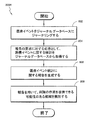
0 is shown. In a particular embodiment, the
It is executed by one of the interface modules. Further, the
方法400では、まず、402で、状況情報を受信する。一実施形態では、ネットワー
ク・インタフェース・モジュールのような装置が、状況情報を一度(初期化ステップなど
において)受信する。次に方法400は、404で、生理学的情報を受信する。特定実施
形態では、方法400は、方法400の残りのステップの全体にわたって生理学的情報の
受信を続ける。代替として、方法400は、方法400の一部において生理学的情報40
0を受信してもよい。
The
0 may be received.
405で、方法400は、アラーム状態またはアラートが発生しているかどうかを判定
する。アラーム状態またはアラートが発生している場合、方法400は406に進む。一
方、アラーム状態またはアラートが発生していない場合、方法400は404に戻る。一
実施形態では、方法400が404に戻ることは、アラーム状態またはアラートが発生す
るまでネットワーク・インタフェース・モジュールが生理学的情報を連続して受信するこ
とを表す。特定実施形態(図示せず)では、方法400は、アラーム状態またはアラート
が発生した場合でも生理学的情報の受信を続けてよい。
At 405,
406で、方法400は、状況データパッケージを用意する。状況データパッケージは
、状況情報と、生理学的情報のスナップショットとを含むことが可能である。一実施形態
では、生理学的情報のスナップショットは、アラームまたはアラートを引き起こした生理
学的情報を含む。一実施形態では、生理学的情報のスナップショットは、アラームまたは
アラートの発生前後の情報を含む。状況データパッケージは、408で、フロー制御バッ
ファに格納される。
At 406, the
410で、方法400は、ネットワーク接続を確立する。一実施形態では、410でネ
ットワーク接続を確立することは、ネットワーク・インタフェース・モジュールをエンド
ユーザ装置(たとえば、勤務シフト中の看護師に割り当てられた通知装置)に接続するこ
とを含む。次に方法400は、412で、エンドユーザ装置のユーザ(たとえば、看護師
)が認証済みかどうかを判定する。ユーザが認証済みでない場合、方法400は420に
進む。一方、ユーザが認証済みである場合、方法400は414に進む。
At 410, the
方法400は、414で、状況データパッケージをユーザに伝達する。416で、方法
400は、状況データパッケージが受信されたかどうかを判定する。状況データパッケー
ジが受信された場合、方法400は420に進む。受信されていない場合、方法400は
418に進み、418で、フロー制御バッファに格納されているデータにアクセスする。
一実施形態では、この、方法400でアクセスされるデータは、414でユーザに伝達さ
れた状況データパッケージと同等またはほぼ同等である。
The
In one embodiment, the data accessed in this
次に方法400は、414に戻り、414で、状況データパッケージをユーザに伝達(
たとえば、再送信)し、次に、416で、パッケージが受信されたかどうかを再確認する
。方法400は、実装によっては、状況データパッケージが受信されるまで、ステップ4
14、416、および418の間のループを続ける。したがって、特定実施形態における
ステップ414、416、および418は、方法400で実行されるフロー制御を構成し
ている。これらのフロー制御ステップにより、方法400は、共用ネットワークにおいて
発生しうるネットワーク送信エラーを克服することが可能になる。
The
For example, retransmit) and then at 416 recheck to see if the package has been received. The
Continue the loop between 14, 416 and 418. Thus, steps 414, 416, and 418 in certain embodiments constitute the flow control performed in
状況データパッケージが受信された場合、方法400は、420で、生理学的情報の監
視を続けるかどうかの評価を行う。監視を続けることを決定した場合、方法400は40
4に戻り、404で、生理学的情報の受信を続ける。一方、監視を続けないことを決定し
た場合、方法400は終了する。
If a status data package is received, the
Returning to 4, at 404, continue receiving physiological information. On the other hand, if it is decided not to continue monitoring, the
方法400の様々な実施形態では、アラーム状態がない場合でも、状況データパッケー
ジまたは生理学的情報のみがユーザに送信される。さらに別の実施形態では、上記ステッ
プのすべてより少ないステップが実行されたり、上記ステップが別の順序で実行されたり
する。たとえば、方法400は、404で生理学的情報を受信するステップを実行し、4
06で状況データパッケージを用意するステップを実行し、410でネットワーク接続を
確立するステップを実行し、414で状況データパッケージをユーザに伝達するステップ
を実行するだけでもよい。
In various embodiments of the
The step of preparing a status data package may be performed at 06, the step of establishing a network connection may be performed at 410, and the step of communicating the status data package to the user may be performed at 414.
図5は、本発明の特定実施形態によるアラーム通知システム500を示す。臨床サブシ
ステム510が、アラーム通知システム500の主要ソフトウェアコンポーネントを定義
しており、これには、臨床割り当てモジュール512、ベッドサイド装置初期化モジュー
ル514、通知および表示モジュール516、エスカレーション・ルール・モジュール5
18、臨床報告モジュール520、および臨床データ格納モジュール522が含まれる。
HIPAAおよび病院IT方針に準拠したモバイルコンピューティング装置には、認証機
能が組み込まれている。
FIG. 5 illustrates an
18, a
Mobile computing devices that comply with HIPAA and hospital IT policies incorporate an authentication function.
臨床割り当てモジュール512は、割り当て機能を有する。看護監督者は、各シフトの
開始時および新しい患者の入院時に、個々の看護師を特定の患者に割り当てる。シフト割
り当てが行われるのは、「報告」移行活動時のシフト変更においてであり、ここで、前の
シフトからの個々の看護師および看護監督者が患者を次のシフトに「引き継ぐ」。この報
告は、病院の看護サービス方針および手続きに応じて、全看護師が出席する公式なもので
あっても、非公式なものであってもよい。臨床割り当てモジュール512は、割り当て可
能な看護師のリストに個々の患者を割り当てることを可能にする、直観的なインタフェー
スを提供する。このモジュールの主なユーザは、看護監督者から任命された病棟事務員で
ある。看護師には、1人以上の患者、または全患者を割り当てることが可能である。代替
の作業フローとして、自己割り当てがある。これは、個々の看護師が自身に患者を割り当
てるものであり、この場合は、看護師が病棟事務員の役割を果たす。自己割り当てモデル
では、割り当てのない患者がいれば、その患者は全看護師または看護監督者に割り当てら
れるのがデフォルトの実施態様である。
The
ベッドサイド装置初期化モジュール514は、上述のネットワーク・インタフェース・
モジュールのようなベッドサイド装置であって、看護助手によってセットアップされるこ
とがある。看護師がこの作業を行う場合には、看護師が看護助手の役割を果たすことにな
る。作業フローに含まれるのは、装置をベッドサイドに設置すること、センサを装着する
こと、装置を初期化すること、名前、ID、場所などの患者状況を設定することなどであ
る。
The bedside device initialization module 514 includes the network interface interface described above.
A bedside device such as a module that may be set up by a nursing assistant. If the nurse performs this task, the nurse will serve as a nursing assistant. Included in the workflow is installing the device on the bedside, wearing sensors, initializing the device, setting patient status such as name, ID, location, etc.
通知および表示モジュール516は、無線通知装置(単方向ページャ、PDA、IP電
話、COW、またはタブレット)を個々の看護師に割り当てる。この装置は、各看護師に
関連付けられる。臨床割り当てモジュール512に基づいて、アラームが通知装置に向け
て経路設定される。病院が保有するページングシステムが看護師に支給される場合のよう
な非専用通知装置ソリューションは、待ち時間特性が不明である。サーバでは、ベッドサ
イド装置からの受信後の待ち時間が1秒未満である汎用インタフェースが利用可能であり
、この汎用インタフェースは、サーバ外部インタフェースへの提示時にタイムスタンプが
なされ、タイムスタンプはサーバ内のジャーナリングシステムに格納される。PDA、C
OWS、タブレットなどのモバイルコンピューティングプラットフォーム用のインタフェ
ースを追加することにより、個々の患者の現在のデータおよび動向データの表示が可能に
なる。
The notification and display module 516 assigns a wireless notification device (unidirectional pager, PDA, IP phone, COW, or tablet) to individual nurses. This device is associated with each nurse. Based on the
By adding interfaces for mobile computing platforms such as OWS, tablets, etc., it is possible to display current and trend data for individual patients.
エスカレーション・ルール・モジュール518は、病院によって定義されたエスカレー
ションポリシーを発動させるルールエンジンを有する。エスカレーション・ルール・モジ
ュール518は、アラームへの対応がない場合、またはアラームが(たとえば、ポリシー
によって)事前定義された時間にわたって持続している場合に、代替および追加の臨床ユ
ーザに向けてアラームの代替経路設定を行う。特定実施形態におけるエスカレーション・
ルール・モジュール518は、緊急対応チームに向けてアラームの経路設定を行う。
The escalation rules
The
臨床報告モジュール520は、生理学的状態および/または進行を判断する材料となる
臨床データに関して、事前定義されたフォーマットで報告を行う。エンドユーザの必要に
応じて、2つ以上の報告が可能である。報告は、個々の患者に関するタイムクリティカル
な表示ではなく、アラーム通知システム500の特権を有し、アラーム通知システム50
0によって認証済みの臨床担当者が離れた場所から見ることが可能である。これらの報告
は、Webブラウザ表示であって、臨床担当者は、時間およびパラメータの尺度やアラー
ムの再表示などの表示パラメータを設定することが可能である。
The
0 allows clinical personnel who have been authenticated to see from a distance. These reports are Web browser displays that allow clinicians to set display parameters such as time and parameter scales and alarm redisplays.
臨床データ格納モジュール522は、当業者であれば既知であるように、情報を格納す
るためのデータ記憶装置およびデータベースリソースを提供する。
The clinical
図5はさらに、技術的サポートサブシステム530を示しており、これは、HIPAA
に準拠した臨床サブシステム510と隔離されており、したがって、リスク報告モジュー
ル538を除いて、どの患者情報も閲覧できず、アクセスできない。技術的サポートサブ
システム530は、プロビジョニングモジュール532、管理モジュール、サービスモジ
ュール536、リスク報告モジュール538、および技術的データ格納モジュール540
を含んでいる。
FIG. 5 further shows a
Is isolated from the
Is included.
プロビジョニングモジュール532は、プロビジョニング、すなわち、システムおよび
顧客の初めての使用の初期インストールを提供する。プロビジョニングモジュール532
の主なユーザは、フィールドインストール担当者である。プロビジョニングモジュール5
32は、システムを出荷用梱包から出してアラーム通知システム500の機能性を完全な
ものにするためのスタートアップスクリプトおよびシステム構成をすべて収容している。
プロビジョニングは、顧客現場の個々の装置、ページャのような通知装置、PDA、CO
W、テーブル、およびIP電話を、好ましくは無線手段(たとえば、Bluetooth
(登録商標))によって構成するステップを含んでいる。
The
The main user is a field installer.
32 contains all of the startup scripts and system configuration to unpack the system from the shipping packaging and complete the functionality of the
Provisioning includes individual devices at the customer site, notification devices such as pagers, PDAs, CO
W, tables, and IP phones are preferably wireless means (eg, Bluetooth
(Registered trademark)).
管理モジュール534は、ユーザのセットアップ、各種の役割別特権に関するポリシー
(看護助手はアラームの設定または変更ができる、など)の設定、許可される装置接続の
識別ならびに他の、ITシステムによくある一般システム管理業務のセットアップを、ア
プリケーション管理者が行うためのシステムインタフェースを提供する。
The
サービスモジュール536は、リモートサービス、ITサービス、生物医学的サービス
などの様々な技術的サポート担当者のためのインタフェースを提供する。これらの各担当
者は、互いの役割を実行してよい。サービス担当者は、インタフェースを用いて、システ
ム性能データにアクセスすることにより、性能、たとえば、データトラフィック、接続さ
れている装置資産、ソフトウェアバージョン管理、CPUローディング、ネットワークロ
ーディングなどにアクセスすることが可能になり、また、リモート技術的サービス手続き
、たとえば、プリンタキューのリセット、ディスクの再パーティション、ソフトウェアパ
ッチのアップロードなどを実行することが可能になる。サービスモジュール536は、シ
ステムによってキャプチャ可能なすべてのユーザ対話または一部のユーザアクション(特
に、デフォルト値やアラーム設定の変更)を格納する、完全なジャーナリング機能を含ん
でいる。
リスク報告モジュール538は、JCAHO、他の規制団体、および内部品質保証委員
会の要求に照らしてアラームに対する臨床的対応の全体的な効果を判定するための、アラ
ーム発生、アラーム継続時間、アラームから臨床的対応までの時間、および他の統計デー
タに関する要約報告を提供する。
The
技術的データ格納モジュール540は、技術的データに関して用いられる点以外は、臨
床データ格納モジュール522と同等の特性を有する。技術的データ格納モジュール54
0は、臨床データ格納モジュール522と同じ物理的かつ論理的エンティティを共用して
もしなくてもよい。
The technical
0 may or may not share the same physical and logical entity as the clinical
図5はさらに、外部インタフェースサブシステム550を示しており、これは、ベッド
サイド装置および外部システムとのインタフェースを提供するものであり、たとえば、電
子医療記録、入院退院転院システム、POCSAGページャシステム、ミドルウェアエン
ジン(Emerginなど)、Web/XML対応装置(無線PDA、COW、タブレッ
トPCなど)などとのインタフェースを提供する。外部インタフェースサブシステム55
0は、HL7インタフェース552、ページャインタフェース554、XML/Webイ
ンタフェース556、および装置インタフェース558を有する。
FIG. 5 further illustrates an
0 has an
HL7インタフェース552は、電子医療記録(EMR)に対する双方向インタフェー
スを提供し、プッシュモデルおよびプルモデルの両方をサポートしている。プッシュモデ
ルは、ベッドサイドの看護師がデータ転送を起動する場合である。プルモデルは、EMR
システムがアラーム通知システム500サーバをポーリングする場合である。ページャイ
ンタフェース554は、外部ページングシステムへの出力を提供する。メッセージ待ち時
間は、どのようなユーザ保有のページングソリューションの場合も、エンドユーザに特定
される。この同じ出力を、Emerginのようなミドルウェアアラーム通知システムに
用いることが可能である。XML/Webインタフェース556は、モバイルコンピュー
ティングプラットフォーム(無線PDA、COW、テーブル、Web対応IPフォンなど
)との双方向インタフェースを提供する。モバイルコンピューティングプラットフォーム
は、WebブラウザのXMLアプリケーションをサポートしている。装置インタフェース
558は、ベッドサイド装置ならびに他の、通信モジュールまたはアクセサリに対応する
装置に対する双方向インタフェースを提供する。他のベッドサイド装置にインタフェース
するためのオプションとして、アプリケーションプログラマインタフェース(API)機
能がある。
The
This is the case when the system polls the
アラーム通知システム500システムの(簡潔さのために図示または記載していない)
主なエンドユーザは、病院電子医療記録、入院退院転院、調剤、臨床情報、患者フロー追
跡などを含む。各担当者(たとえば、アラーム通知システム500のユーザ)は、臨床担
当者および技術的サポート担当者を含んでいる。臨床担当者は、看護監督者、病棟事務員
、看護助手、看護師、即応チーム、呼吸療法士などである。
Primary end users include hospital electronic medical records, hospital discharges, dispensing, clinical information, patient flow tracking, and the like. Each person (eg, a user of the alarm notification system 500) includes a clinical person and a technical support person. The clinical staff is a nursing supervisor, ward clerk, nursing assistant, nurse, responsive team, respiratory therapist, etc.
看護監督者は、各シフトの開始時に個々の看護師を特定の患者に割り当てる。シフトは
、病院の要員配置方針に応じて変わる可能性がある。病棟事務員は、看護監督者から指示
を受け、典型的には、割り当てをシステムに入力し、システム全体を監視する。病棟事務
員は、すべてのシフトにわたって待機していなくてもよい。看護助手は、看護師または看
護監督者から割り当てを受け、典型的には、ベッドサイド装置センサを装着し、ベッドサ
イド装置を初期化し、アラームをデフォルト値に設定する。看護師は、個々の患者の看護
と、アラームへの最初の対応とに主たる責任を有する。看護監督者は、看護師のスキルと
患者のニーズとに応じて2人以上の患者を看護師に割り当てる。看護師には、いつも同じ
患者が割り当てられるわけではない。看護助手は、どの病院にもいるわけではない。
The nursing supervisor assigns individual nurses to specific patients at the start of each shift. Shifts may vary depending on hospital staffing policies. The ward clerk receives instructions from the nursing supervisor and typically enters assignments into the system and monitors the entire system. The ward clerk does not have to wait for every shift. A nursing assistant is assigned by a nurse or nurse supervisor and typically wears a bedside device sensor, initializes the bedside device, and sets the alarm to a default value. The nurse is primarily responsible for the care of the individual patient and the first response to the alarm. The nurse supervisor assigns two or more patients to the nurse according to the nurse's skills and the patient's needs. Nurses are not always assigned the same patient. Nursing assistants are not in every hospital.
即応チームは、ベッドサイドの看護師または看護監督者から発動された臨床緊急事態に
対応する。即応チームは、2つ以上の治療室をサポートし、シフトに応じて1人以上のメ
ンバーを有する。即応チームは、すべての病院に配備されなくてもよい。呼吸療法士は、
2人以上の患者、ならびに通常は2つ以上の治療室の呼吸治療を管理する責任を有する。
一部の国際環境では、呼吸療法士を置かない。
The responsive team responds to a clinical emergency triggered by a bedside nurse or nurse supervisor. The responsive team supports two or more treatment rooms and has one or more members in response to a shift. Immediate teams may not be deployed at all hospitals. The respiratory therapist
Responsible for managing respiratory therapy for two or more patients, and usually two or more treatment rooms.
In some international environments, there is no respiratory therapist.
臨床担当者の作業置換により、能力の高い担当者が他の担当者の役割を担うことが可能
である。アラーム通知システム500は、そのようなことを実行するためのメカニズムを
可能にする。たとえば、看護監督者は、病棟事務員、看護助手、看護師、および即応チー
ムの役割を果たすことが可能である。看護師は、病棟事務員、看護助手、および即応チー
ムの役割を果たすことが可能である。一部の国際市場では、看護師が呼吸療法士の役割を
果たすことが可能である。
By replacing the work of clinical personnel, it is possible for highly qualified personnel to take the role of other personnel. The
技術的サポート担当者は、フィールドインストール担当者、アプリケーション管理者、
リモートサービス、IT技術者、生物医学技術者、リスク管理者などである。フィールド
インストール担当者は、初期インストールのためのシステムのプロビジョニングを行い、
各コンポーネントをインストールし、インストールおよび構成が購買契約を満たすかどう
かを検証する。アプリケーション管理者は、ユーザアカウントおよびシステムをデフォル
トにセットアップし、維持する。リモートサービスは、ダイヤルアップやVPNのような
リモートリンクを経由するリモート診断およびシステムメンテナンスを提供する。IT技
術者は、システムが病院ITネットワークと一体化されている場合に、ネットワークサポ
ートサービスを提供する。生物医学技術者は、ベッドサイドおよびシステムの一次サービ
スを提供する。リスク管理者は、品質およびリスク軽減のために報告を精査する。技術的
サポート担当者は、他の担当者の代わりを務めることもある。たとえば、IT技術者、生
物医学技術者、またはリモートサービスは、アプリケーション管理者の役割を果たすこと
も可能である。IT技術者または生物医学技術者は、互いの役割を果たすことも可能であ
る。
Technical support personnel include field installers, application administrators,
Remote services, IT engineers, biomedical engineers, risk managers, etc. The field installer will provision the system for the initial installation,
Install each component and verify that the installation and configuration meets the purchase agreement. The application administrator sets up and maintains user accounts and systems as default. Remote services provide remote diagnostics and system maintenance via remote links such as dial-up and VPN. IT technicians provide network support services when the system is integrated with a hospital IT network. Biomedical engineers provide primary services for bedside and systems. The risk manager reviews the report for quality and risk mitigation. Technical support representatives may take the place of other representatives. For example, an IT engineer, biomedical engineer, or remote service can also act as an application administrator. IT engineers or biomedical engineers can also play roles with each other.
特定実施形態では、生理学的動向データを迅速に格納および取得するシステムおよび方
法を提供する。たとえば、医療患者から取得された生理学的情報を、ラウンドロビンデー
タベースに格納することが可能である。ラウンドロビンデータベースは、生理学的情報を
、時間的に等間隔である一連のレコードの形で格納することが可能である。パラメータ記
述子を用いると、レコード内のパラメータ値を識別することが可能である。パラメータ記
述子を変更することによって、パラメータ値を動的に更新することが可能であり、これに
よってデータベースがフレキシブルになる。さらに、データベースに用いるファイルのサ
イズは、患者の状態に応じて、動的に調節することが可能である。
Certain embodiments provide systems and methods for rapidly storing and retrieving physiological trend data. For example, physiological information obtained from a medical patient can be stored in a round robin database. A round robin database can store physiological information in a series of records that are equally spaced in time. Using parameter descriptors, it is possible to identify parameter values within a record. By changing the parameter descriptor, the parameter value can be updated dynamically, which makes the database flexible. Furthermore, the size of the file used for the database can be dynamically adjusted according to the patient's condition.
さらに、特定実施形態では、臨床ネットワークの生理学的監視器から取得された医療デ
ータを、ジャーナルデータベースに格納またはジャーナリングすることが可能である。こ
の医療データは、臨床担当者と1つ以上の医療装置との対話に対する応答として発生した
装置イベントを含むことが可能である。医療イベントデータは、装置から発動されたイベ
ント(アラームなど)を含むことも可能である。ジャーナルデータベースに格納された医
療データを分析して統計または指標を導出することが可能であり、これらを用いて、臨床
担当者および/または病院の作業成果を向上させることが可能である。
Further, in certain embodiments, medical data obtained from a clinical network physiological monitor can be stored or journaled in a journal database. This medical data can include device events that occur in response to interactions between the clinician and one or more medical devices. The medical event data can also include events (such as alarms) triggered from the device. The medical data stored in the journal database can be analyzed to derive statistics or indicators that can be used to improve the work performance of clinicians and / or hospitals.
本明細書で用いる用語「ラウンドロビンデータベース」および「RRDB」は、その本
来の意味に加えて、本明細書で開示される独特の特性および特徴を有する、改良されたデ
ータベース構造を示す場合もある。本明細書では、これらの構造を動的RRDBまたは適
応RRDBと称することもある。
As used herein, the terms “round robin database” and “RRDB”, in addition to their original meaning, may indicate an improved database structure having the unique characteristics and features disclosed herein. . In the present specification, these structures are sometimes referred to as dynamic RRDB or adaptive RRDB.
図6は、臨床ネットワーク環境600の一実施形態を示す。臨床ネットワーク環境60
0は、1つ以上の患者監視器640、看護師詰所システム630、および臨床担当者装置
650とネットワーク610経由で通信する多患者監視システム(MMS)620を含ん
でいる。特定実施形態では、MMS 620は、患者監視器640から取得された生理学
的データを、看護師詰所システム630および/または臨床担当者装置650に提供する
。さらに、特定実施形態では、MMS 620は、生理学的情報および医療イベント情報
を、後刻の分析のために格納する。
FIG. 6 illustrates one embodiment of a
0 includes one or more patient monitors 640, a nurse station system 630, and a multi-patient monitoring system (MMS) 620 that communicates with the clinician device 650 via the
臨床ネットワーク環境600のネットワーク610は、LANまたはWAN、無線LA
N(「WLAN」)、または他のタイプの、任意の病院、介護施設、患者治療拠点、また
は他の臨床施設で使用されるネットワークであってよい。説明を容易にするために、本明
細書の残りの部分では、病院という状況における臨床環境を説明するが、本明細書に記載
の特徴は、他の臨床施設または設定でも用いることが可能であることを理解されたい。実
装によっては、ネットワーク610は、複数の病院または臨床施設にある装置と相互接続
可能であり、これらの装置は、インターネット、リース回線などを介して、互いに離れて
いてよい。同様に、臨床ネットワーク環境100の各種装置620、630、640、お
よび650は、地理的に(たとえば、複数の病院に)分散していてよく、あるいは、同じ
場所(たとえば、単一病院内)にあってもよい。
The
N (“WLAN”), or other type of network may be used at any hospital, care facility, patient care center, or other clinical facility. For ease of explanation, the remainder of this document describes the clinical environment in a hospital setting, but the features described herein can also be used in other clinical facilities or settings. Please understand that. In some implementations, the
患者監視器640は、医療患者に結合されたセンサによって検出される生理学的信号を
監視するポイントオブケア(POC)計器などであってよい。患者監視器640は、信号
を処理して、様々な生理学的パラメータのいずれかを求めることが可能である。生理学的
パラメータの一例として、血液酸素飽和度(SpO2)がある。生理学的パラメータの他
の例については、後で図7に関して説明する。
患者監視器640は、生理学的情報をMMS 620に提供することが可能である。患
者監視器640はまた、アラームなど、医療イベントに関する情報をMMS 620に提
供することも可能である。アラームは、たとえば、生理学的パラメータが正常範囲から逸
脱することに対する応答としてトリガ可能である。アラームはまた、センサが患者から脱
落したプローブオフ状態のような、機器の障害に関するアラートを含むことも可能である
。後で、医療イベントの他の例を図7に関して説明する。
様々な実施形態において、患者監視器640は、生理学的情報および医療イベントをM
MS 620に提供する。MMS 620については、後で詳述する。実装によっては、
患者監視器640は、この情報の少なくとも一部を看護師詰所システム630および臨床
担当者装置650に直接提供することが可能である。
In various embodiments, patient monitor 640 provides physiological information and medical events to M
Provide to
The patient monitor 640 can provide at least a portion of this information directly to the nurse station system 630 and the clinician device 650.
看護師詰所システム630は、看護師詰所に配置されるデスクトップコンピュータ、ラ
ップトップ、ワークステーションなどであってよい。看護師詰所には、1つ以上の看護師
詰所コンピュータ630を配置することが可能である。看護師詰所コンピュータ630は
、MMS 620(または監視器640)から生理学的情報およびアラームデータを受信
して表示することが可能である。特定実施形態では、看護師詰所コンピュータ630は、
生理学的情報および医療情報を、合理化された、一目でわかるビューで提供するグラフィ
カル・ユーザ・インタフェース(GUI)を使用している。このGUIの一例を、後で図
9に関して説明する。
The nurse station system 630 may be a desktop computer, laptop, workstation, etc. located at the nurse station. One or more nurse station computers 630 can be located in the nurse station. The nurse station computer 630 can receive and display physiological information and alarm data from the MMS 620 (or the monitor 640). In certain embodiments, the nurse station computer 630 includes:
It uses a graphical user interface (GUI) that provides physiological and medical information in a streamlined, at-a-glance view. An example of this GUI will be described later with reference to FIG.
臨床担当者装置650は、臨床担当者が使用する様々な装置のいずれかであってよく、
たとえば、ページャ、携帯電話、スマートフォン、個人用携帯端末(PDA)、ラップト
ップ、タブレットPC、パーソナルコンピュータなどであってよい。実施形態によっては
、臨床担当者装置650は、生理学的情報およびアラームをMMS 620(または監視
器640)から受信することが可能である。生理学的データおよびアラームデータは、特
定の臨床担当者装置650に、たとえば、アラームに対する応答として、提供可能である
。場合により、臨床担当者装置650は、生理学的パラメータの値および波形を受信する
ことが可能である。
The clinician device 650 can be any of a variety of devices used by the clinician,
For example, it may be a pager, a mobile phone, a smartphone, a personal digital assistant (PDA), a laptop, a tablet PC, a personal computer, or the like. In some embodiments, the clinician device 650 can receive physiological information and alarms from the MMS 620 (or monitor 640). Physiological data and alarm data can be provided to a particular clinician device 650, for example, as a response to an alarm. In some cases, the clinician device 650 may receive physiological parameter values and waveforms.
特定実施形態におけるMMS 620は、ネットワーク610内のネットワークトラフ
ィックを管理するためのハードウェアおよび/またはソフトウェアを有する1つ以上の物
理コンピューティング装置(サーバなど)を含んでいる。このハードウェアおよび/また
はソフトウェアは、機能別に、複数の異なるサーバ620に、論理的かつ/または物理的
に分割可能であり、それらは、たとえば、通信サーバ、Webサーバ、データベースサー
バ、アプリケーションサーバ、ファイルサーバ、プロキシサーバなどである。
The
MMS 620は、標準化されたプロトコル(TCP/IPなど)または独自プロトコ
ルを用いて、患者監視器640、看護師詰所コンピュータ630、および臨床担当者装置
650と通信可能である。一実施形態では、患者監視器640がMMS 620との接続
を求めた場合、MMS 620は、その患者監視器640を認証し、患者監視器640に
結合された患者の状況情報を患者監視器640に提供することが可能である。状況情報は
、いろいろなものを含んでよいが、特に、患者のデモグラフィ、患者のアラーム設定、お
よび患者に対する臨床担当者の割り当てを含んでよい。状況情報の例を本明細書に記載し
ている。MMS 620は、この状況情報を、患者の入院情報が与えられている看護師詰
所システム630または他の病院コンピュータシステムから取得可能である。
MMS 620は、患者監視器640に接続するとただちに、生理学的情報および医療
イベントを患者監視器640から受信することが可能である。MMS 620は、それら
の生理学的情報および医療イベントの少なくとも一部を看護師詰所システム630および
/または臨床担当者装置650に提供することが可能である。たとえば、MMS 620
は、複数の患者監視器640に関する生理学的データおよびアラームを看護師詰所システ
ム630に提供することが可能であり、看護師詰所システム630では看護師がそのデー
タおよび/またはアラームを評価して患者の治療方法を決定することが可能である。同様
に、MMS 620は、無線ページ、電子メール、インスタントメッセージなどを臨床担
当者装置650に送信することにより、生理学的データおよびアラームを臨床担当者に提
供することが可能である。
As soon as the
May provide physiological data and alarms for a plurality of patient monitors 640 to the nurse station system 630, where the nurse evaluates the data and / or alarms to determine the patient's status. It is possible to determine the treatment method. Similarly,
有利なことに、特定実施形態では、MMS 620は、患者監視器640から取得した
生理学的情報をラウンドロビンデータベース(RRDB)624に格納することが可能で
ある。様々な実施形態のRRDB 622は、患者データの迅速な格納および取り出しを
容易にする、合理化されたデータベース構造を有する。したがって、RRDB 622は
、特定実施形態では、生理学的動向データを迅速に看護師詰所630および臨床担当者装
置 650に提供することに用いることが可能である。したがって、たとえば、臨床担当
者が特定時間帯(たとえば、過去1時間)にわたる患者の生理学的動向を見たい場合、臨
床担当者は、看護師詰所コンピュータ630または臨床担当者装置 650を用いてMM
S 620に問い合わせることが可能である。そして、MMS 620は、所望の時間帯
に対応する生理学的情報をRRDB 622から取得することが可能である。有利なこと
に、RRDB 622は、動向データをより迅速に取得できるようにすることが可能であ
るため、病院監視システムで現在使用されているリレーショナルデータベースを用いるこ
とが可能である。RRDB 622のさらなる用法および最適化については後述する。
Advantageously, in certain embodiments, the
It is possible to query S620. The
特定実施形態では、MMS 620はまた、医療イベントに関する情報をジャーナルデ
ータベース624にアーカイブまたは格納する。医療イベントは、患者監視器640、看
護師詰所システム630、および臨床担当者装置650のような装置によって記録された
イベントを含むことが可能である。具体的には、医療イベントは、臨床担当者と装置との
対話に対する応答として発生する装置イベント(たとえば、臨床担当者の指示によるアラ
ームの機能停止)を含むことが可能である。医療イベントはまた、臨床担当者と装置との
対話がなくても発生する装置イベント(たとえば、アラームそのもの)も含むことが可能
である。医療イベントのさらなる例については、後で図7に関して説明する。
In particular embodiments,
MMS 620は、ジャーナルデータベース624に格納された医療イベント情報を分
析して、医療イベントに関する統計を導出することが可能である。たとえば、MMS 6
20は、アラームイベントおよびアラーム機能停止イベントを分析して、アラームから臨
床的対応までの時間を求めることが可能である。MMS 620は、これらの統計を用い
て、臨床担当者および/または病院の作業成果に関する報告を生成することが可能である
。有利なことに、特定実施形態では、これらの統計および報告を用いて、臨床担当者およ
び病院の作業成果を向上させることが可能である。
The
20 can analyze alarm events and alarm outage events to determine the time from alarm to clinical response. The
たとえば、特定状況では、これらの報告は、病院が問題の原因を患者監視器640で見
つけることに役立ちうる。以下のシナリオ例は、そのような報告の潜在的利点を示すこと
ができる。SpO2アラームレベルは、成人と新生児とで異なる傾向がある。しかしなが
ら、臨床担当者によってはこのことが知られていない場合があり、新生児用SpO2監視
器に成人のアラームレベルを含める変更が行われる可能性がある。このような変更は、誤
アラームの多発を引き起こす可能性があり、これによって、臨床担当者は、苛立ったり、
患者監視器640の使用を避けたりする可能性がある。臨床担当者によるアラーム変更の
ような医療イベントをジャーナリングし、ジャーナリングされたデータを分析することに
より、臨床担当者が新生児用監視器のアラーム設定を不適切に調節していたことが判明す
る可能性がある。その場合、病院は、この情報を用いて是正措置を行うことが可能である
(たとえば、アラーム限界を固定し、臨床担当者のトレーニングを行うなど)。
For example, in certain situations, these reports can help the hospital find the cause of the problem with the
The patient monitor 640 may be avoided. Journaling medical events such as alarm changes by a clinician and analyzing the journaled data may reveal that the clinician was improperly adjusting the alarm settings on the neonatal monitor There is. In that case, the hospital can use this information to take corrective action (eg, fix alarm limits and train clinical personnel).
図示していないが、臨床ネットワーク環境600内に管理装置を設けることが可能であ
る。管理装置は、病院管理者、IT担当者などが操作するコンピューティング装置を含む
ことが可能である。たとえば、IT担当者は、管理装置を用いて、複数の患者監視器64
0、看護師詰所システム630、およびMMS 620に変更を周知させることが可能で
ある。また、管理装置によって、IT担当者は、サードパーティシステム(たとえば、電
子医療記録(EMR)システム)をMMS 620とインタフェースさせることが可能に
なる。たとえば、サードパーティシステムを用いることにより、複数の監視器のアラーム
設定の変更を管理装置から行うことが可能になる。一般に、管理者、IT担当者、および
管理装置によって行われるアクションも、ジャーナルデータベース624にジャーナリン
グすることが可能である。
Although not shown, a management device can be provided in the
0, the nurse station system 630, and the
図7は、臨床ネットワーク環境700のより詳細な実施形態を示す。臨床ネットワーク
環境700は、ネットワーク710と、患者監視器740と、看護師詰所システム730
と、MMS 720と、RRDB 722と、ジャーナルデータベース724とを含んで
いる。これらのコンポーネントは、図6に関して上述した機能性をすべて含んでよい。説
明を簡単にするために、監視器740および看護師詰所システム730は1つずつ図示し
た。さらに、図示していないが、上述した臨床担当者装置750も、臨床ネットワーク環
境700に含めることが可能である。
FIG. 7 illustrates a more detailed embodiment of a
患者監視器740の図示した実施形態は、監視モジュール742、RRDBモジュール
744、およびジャーナルモジュール746を含んでいる。これらのモジュールのそれぞ
れは、ハードウェアおよび/またはソフトウェアを含んでよい。他のコンポーネント(通
信モジュールなど)は図示していないが、様々な実装において患者監視器740に含めて
よい。
The illustrated embodiment of patient monitor 740 includes a
監視モジュール742は、患者に結合された1つ以上のセンサから発生した生理学的信
号を監視することが可能である。監視モジュール742は、信号を処理して、様々な生理
学的パラメータのいずれかを求めることが可能である。たとえば、監視モジュール742
は、脈拍数、プレチスモグラフ波形データ、灌流指数、体内組織中の血液成分の各値など
の生理学的パラメータを求めることが可能であり、血液成分の各値としては、たとえば、
動脈血一酸化炭素飽和度(「HbCO」)、メトヘモグロビン飽和度(「HbMet」)
、総ヘモグロビン(「HbT」または「SpHb」)、動脈血酸素飽和度(「SpO2」
)、動脈血酸素飽和分率(「SpaO2」)、酸素含有量(「CaO2」)などがある。
The
Can determine physiological parameters such as pulse rate, plethysmograph waveform data, perfusion index, and blood component values in body tissues. Examples of blood component values include:
Arterial blood carbon monoxide saturation (“HbCO”), methemoglobin saturation (“HbMet”)
, Total hemoglobin (“HbT” or “SpHb”), arterial oxygen saturation (“SpO 2 ”)
), Arterial oxygen saturation fraction (“SpaO 2 ”), oxygen content (“CaO 2 ”) and the like.
さらに、監視モジュール742は、音響センサから生理学的情報を取得することが可能
であり、これは、呼吸数、吸気時間、呼気時間、吸気時間呼気時間比、吸気流、呼気流、
一回換気量、分時拍出量、無呼吸継続時間、呼吸音、ラ音、水泡音、喘鳴、呼吸音の変化
(空気流量の減少または空気流の変化など)などを求めるために行う。さらに、場合によ
っては、監視モジュール742は、他の生理学的音を監視し、それらは、(たとえば、プ
ローブオフ検出に役立つ)心拍数、心音(たとえば、S1、S2、S3、S4、および心
雑音)、心音の変化(たとえば、正常音から心雑音への変化や、体液過剰を表す分裂心音
)などである。さらに、監視モジュール742は、心電図検査(ECG)による、患者の
心臓の電気的活動の監視や、他の様々な生理学的パラメータの監視を行うことが可能であ
る。
Further, the
This is done to determine tidal volume, minute volume, apnea duration, breathing sound, rar, bubbling sound, wheezing, changes in breathing sound (decrease in air flow or change in airflow, etc.). Further, in some cases, the
実装によっては、患者監視器740は、様々なデータ信頼性指標を求めることも可能で
あり、たとえば、参照によって開示の全体が本明細書に組み込まれている米国特許第70
24233号明細書(件名「Pulse oximetry data confide
nce indicator」)に記載されているデータ信頼性指標を求めることも可能
である。また、患者監視器740は、灌流指数を求めることも可能であり、たとえば、参
照によって開示の全体が本明細書に組み込まれている米国特許第7292883号明細書
(件名「Physiological assessment system」)に記載
されている灌流指数を求めることも可能である。さらに、患者監視器740は、プレチス
モグラフ変動指数(PVI)を求めることも可能であり、たとえば、参照によって開示の
全体が本明細書に組み込まれている米国特許出願公開第2008/0188760号明細
書(件名「Plethysmograph variability processo
r」)に記載されているPVIを求めることも可能である。本明細書に記載の各パラメー
タは、例に過ぎず、特定実施形態では他にも様々なパラメータを使用することが可能であ
る。
In some implementations, the patient monitor 740 may determine various data reliability indicators, for example, US Pat. No. 70, the disclosure of which is incorporated herein by reference in its entirety.
No. 24233 (Subject “Pulse Oximeter Data Data Confide”
It is also possible to obtain the data reliability index described in “nce indicator”). The patient monitor 740 can also determine a perfusion index, see, for example, US Pat. No. 7,292,883 (subject “Physiological assessment system”), the entire disclosure of which is incorporated herein by reference. It is also possible to determine the described perfusion index. In addition, the patient monitor 740 can determine a plethysmograph variability index (PVI), for example, US Patent Application Publication No. 2008/0188760, the entire disclosure of which is incorporated herein by reference. Subject “Plethysmography variability process”
It is also possible to determine the PVI described in r "). Each parameter described herein is only an example, and various other parameters can be used in certain embodiments.
特定実施形態では、RRDBモジュール744は、監視モジュール742から生理学的
情報を受信し、この生理学的情報をネットワーク710経由でMMS 720に送信する
。応答として、MMS 220は、生理学的情報をRRDB 722に格納することが可
能である。有利なことに、特定実施形態では、RRDBモジュール744は、生理学的情
報をMMS 720に送信する前にパラメータ記述子に関連付ける。パラメータ記述子は
、RRDBモジュール744が生理学的パラメータの各測定値に関連付ける識別子であっ
てよい。MMS 720は、これらのパラメータ記述子を用いて、RRDBモジュール7
44から受信した測定パラメータのタイプを識別することが可能である。
In particular embodiments, the
The type of measurement parameter received from 44 can be identified.
パラメータ記述子は、マークアップ言語仕様、たとえば、拡張可能マークアップ言語(
XML)仕様に従って生成された記述子であってよい。したがって、パラメータ記述子は
、測定された生理学的値を囲むタグを含むことが可能である。これらのタグは、機械可読
であっても人間可読であってもよい。たとえば、タグは、数値的識別子(たとえば、「0
017」)や記述的識別子(「SPO2」や「SPHB」など)を含んでよい。パラメー
タ記述子に関連付けられたSpO2センサおよびSpHbセンサからの生理学的情報の簡
略化されたストリーム例は、たとえば、<SPO2>96</SPO2> <SPHB>
14.1</SPHB> <SPO2>97</SPO2> <SPHB>14.0</
SPHB>(以降も続く)のようになる。
A parameter descriptor is a markup language specification, such as an extensible markup language (
It may be a descriptor generated according to the XML) specification. Thus, the parameter descriptor can include a tag that surrounds the measured physiological value. These tags may be machine readable or human readable. For example, a tag can be a numeric identifier (eg, “0
017 ") and descriptive identifier (such as" SPO 2 "and" SPHB ") may contain. A simplified stream example of physiological information from SpO 2 and SpHb sensors associated with a parameter descriptor is, for example, <SPO2> 96 </ SPO2><SPHB>
14.1 </ SPHB><SPO2> 97 </ SPO2><SPHB> 14.0 <//
SPHB> (and so on).
一実施形態では、RRDBモジュール744は、患者監視器740で利用可能な事前定
義済みパラメータ記述子のセットを(たとえば、データファイルとして)格納しておくこ
とが可能である。これらのパラメータ記述子は、患者監視器740で測定可能な、予想さ
れるパラメータに対応することが可能である。RRDBモジュール744から送信される
パラメータ記述子は、患者監視器740で測定されるパラメータの特定のサブセットに依
存してよい。
In one embodiment, the
患者監視器740によって、追加(または別)のパラメータが連続して測定される場合
、RRDBモジュール740は、MMS 720に送信されたパラメータ記述子を動的に
更新してよい。同様に、患者監視器740がいずれかのパラメータの測定を中止する場合
、RRDBモジュール744は、対応するパラメータ記述子をMMS 720に送信する
ことを中止してよい。
If additional (or other) parameters are continuously measured by
図示した実施形態では、患者監視器740はまた、ジャーナルモジュール746を含ん
でいる。ジャーナルモジュール740は、患者監視器740に関連する医療イベントを記
録することが可能である。これらの医療イベントは、臨床担当者が発動させたイベントを
含むことが可能であり、たとえば、アラーム設定(たとえば、最大および最小許容パラメ
ータ値)、監視対象パラメータのタイプ、患者監視器740に接続されるセンサのタイプ
などを変更することを含むことが可能である。ジャーナルモジュール746は、これらの
イベントを記録することが可能であり、これは、たとえば、臨床担当者のボタン押しを記
録するキーロガーなどとして動作することにより可能である。ジャーナルモジュール74
6はまた、センサまたはケーブルが患者監視器740に接続されたことを検出する電流検
知回路などを含むことも可能である。医療イベントはまた、非臨床担当者が発動させたイ
ベント(アラームやアラートなど)を含んでよい。医療イベントはまた、ネットワーク7
10の全体にわたるアラーム設定のEMR更新のような、管理装置(図示せず)からのイ
ベントも含んでよい。
In the illustrated embodiment, patient monitor 740 also includes a
6 can also include a current sensing circuit or the like that detects when a sensor or cable is connected to the
An event from a management device (not shown), such as an EMR update of 10 global alarm settings, may also be included.
ジャーナルモジュール746は、これらのイベントを、患者監視器740でローカルに
ログ記録することが可能である。ジャーナルモジュール746は、イベントをローカルに
ログ記録することに加えて、またはその代わりに、これらのイベントに関する情報をMM
S 720に送信することが可能である。そして、MMS 720は、このイベント情報
をジャーナルデータベース724に格納することが可能である。
The
It is possible to transmit to S720. The
看護師詰所システム730は、図示した実施形態では、患者監視クライアント732を
有しているように示した。患者監視クライアント732は、看護師詰所システム730が
生理学的情報およびアラーム情報を受信および表示できるようにすることが可能である。
患者監視クライアント732は、ユーザ・インタフェース・モジュール734を含んでい
る。ユーザ・インタフェース・モジュール734は、たとえば、複数の患者監視器740
についての生理学的情報、患者情報、および医療イベント情報を表示するソフトウェアを
含むことが可能である。ユーザ・インタフェース・モジュール734はまた、患者の入退
院や装置アラーム限界のリモート変更などを臨床担当者が行えるようにすることも可能で
ある。ユーザ・インタフェース・モジュール734で生成可能なユーザインタフェースの
一例について、後で図9に関して説明する。
The
Software that displays physiological information, patient information, and medical event information about the device. The
患者監視クライアント732はさらに、ジャーナルモジュール736を含んでいる。ジ
ャーナルモジュール736は、患者監視クライアント732に関連する医療イベントを記
録するソフトウェアを含むことが可能である。たとえば、ジャーナルモジュール736は
、どの臨床担当者が患者監視クライアント732にログインし、ログオフしたか、ならび
にこれらのイベントがいつ発生したかを記録することが可能であり、入退院イベントを記
録することが可能であり、他の、臨床担当者のキーストローク、マウスクリック、および
患者監視クライアント732との対話を記録することが可能である。ジャーナルモジュー
ル736は、このイベント情報を、看護師詰所システム730にローカルにログ記録した
り、かつ/または、MMS 720に送信したりすることが可能である。
図示したように、MMS 720は、ネットワーク管理モジュール721、RRDB管
理モジュール723、およびジャーナル管理モジュール725を含むことが可能であり、
これらのそれぞれが1つ以上のソフトウェアコンポーネントを含むことが可能である。一
実施形態では、ネットワーク管理モジュール721は、生理学的情報および医療イベント
データを収容したメッセージを患者監視器740から受信する。ネットワーク管理モジュ
ール721は、このデータの少なくとも一部を看護師詰所システム730および図6の臨
床担当者装置650に提供することが可能である。ネットワーク管理モジュール721は
また、生理学的情報をRRDB管理モジュール723に提供し、医療イベントデータをジ
ャーナル管理モジュール725に提供することが可能である。
As shown, the
Each of these can include one or more software components. In one embodiment, the
特定実施形態では、RRDB管理モジュール723は、患者監視器740から受信した
生理学的情報をRRDB 722に格納する。患者監視器740が最初にMMS 720
に接続したとき、または別のときに、RRDB管理モジュール723は、その患者監視器
740に対応する1つ以上のRRDBファイルをRRDB 722内に作成することが可
能である。この1つ以上のファイルの内容は、患者監視器740のタイプに依存してよく
、患者監視器740のシリアル番号、モデル番号、ベンダ識別子、これらの組み合わせな
どによって定義可能である。RRDBファイルの構造および内容の具体例が、参照により
全内容が本明細書に組み込まれている米国特許出願公開第2009/0119330号明
細書に記載されている。
In certain embodiments, the
When connected to or otherwise, the
RRDB管理モジュール723はまた、RRDBに格納されている生理学的動向データ
を、監視器740、看護師詰所システム730、および/または臨床担当者装置への送信
に備えて、ネットワーク管理モジュール721に与えることも可能である。RRDB管理
モジュール723はまた、図8Bに関して後述する目的のために、RRDB 722にあ
る生理学的データをジャーナル管理モジュール725に提供することも可能である。
The
ジャーナル管理モジュール725は、特定の実装では、監視器740および看護師詰所
システム730から医療イベントデータを受信し、このデータをジャーナルデータベース
724に格納することが可能である。一実施形態では、ジャーナルデータベース724は
、リレーショナルデータベースであるが、他の構造も使用可能である。イベントデータの
各エントリは、イベントがいつ発生したかを示す、対応するタイムスタンプを有すること
が可能である。このタイムスタンプは、ジャーナルモジュール746または736、ある
いはジャーナル管理モジュール725によって与えることが可能である。ジャーナル管理
モジュール725はまた、医療イベントの発生回数を反映するイベントカウンタをジャー
ナルデータベース724に格納することが可能である。たとえば、ある時間帯に発生した
アラームの数や、臨床担当者がネットワーク装置にログオンまたはログオフした回数をカ
ウントするカウンタを格納することが可能である。
The
有利なことに、ジャーナル管理モジュール725は、特定実施形態では、ジャーナルデ
ータベース724内の医療データを分析して、臨床担当者および/または病院の作業成果
の統計または指標を求めることが可能である。ジャーナル管理モジュール725は、これ
らの統計にアクセスするためのインタフェースを、看護師詰所システム730または別の
コンピューティング装置のユーザに提供することが可能である。一例示的実施形態では、
ジャーナル管理モジュール725は、アラームイベントおよびアラーム機能停止イベント
を分析して、臨床担当者がアラームに対応するまでの時間を求めることが可能である。ジ
ャーナル管理モジュール725はさらに、看護師の日中および夜間のシフトにおける臨床
担当者の対応までの時間を求めることが可能である。ジャーナル管理モジュール725は
、病院管理者が、たとえば、どのシフトの作業成果が他より良好かを判定できるように、
これらの統計の報告を生成することが可能である。
Advantageously, the
The
It is possible to generate a report of these statistics.
より一般的には、ジャーナル管理モジュール725は、ジャーナルデータベース724
にあるデータから導出される様々な統計を分析して、臨床担当者および/または病院の作
業成果に関する報告を生成することが可能である。報告の一例として、監視報告カードが
あり、これは、導出された統計に少なくとも部分的に基づいて、所与の病院を他の病院と
比べて(または、所与の看護師詰所を他の看護師詰所と比べて、など)格付けするもので
ある。有利なことに、病院管理者、臨床担当者などは、これらの統計および報告を用いて
、臨床担当者および病院の作業成果を向上させることが可能である。
More generally, the
Various statistics derived from the data at can be analyzed to generate reports on clinicians and / or hospital work outcomes. An example of a report is a monitoring report card, which compares a given hospital to another hospital (or a given nurse's station to other care based at least in part on derived statistics). Compared to Shigeru-sho, etc.) Advantageously, hospital managers, clinicians, etc. can use these statistics and reports to improve the performance of clinicians and hospitals.
臨床ネットワーク環境700の機能の一部またはすべては、特定実施形態に適応可能で
ある。たとえば、ジャーナルモジュール746または736のいずれかまたは両方が、ジ
ャーナル管理モジュール725の機能の一部またはすべてを実行することが可能である。
同様に、1つ以上のジャーナルデータベース724を、患者監視器740および/または
看護師ワークステーション730に格納することが可能である。同様に、RRDBモジュ
ール724は、RRDB管理モジュール723の機能の一部またはすべてを実行すること
が可能であり、RRDB 722は、患者監視器740に格納可能である。さらに、実装
によっては、図6の臨床担当者装置650も同様にRRDBモジュールおよび/またはジ
ャーナルモジュールを有することが可能である。他の実施形態では、他にも様々な適応、
構成、および組み合わせが可能である。RRDMの実施形態に関する追加情報が、米国特
許出願公開第2009/0119330号明細書に記載されている。
Some or all of the functionality of the
Similarly, one or
Configurations and combinations are possible. Additional information regarding RRDM embodiments is described in US Patent Application Publication No. 2009/0119330.
図8Aは、医療イベントをジャーナルデータベースにジャーナリングする方法800A
の一実施形態を示す。一実施形態では、方法800Aは、上述のMMSのいずれか(たと
えば、MMS 620または720)によって実装可能である。具体的には、方法800
Aは、ジャーナル管理モジュール725によって実装可能である。代替として、少なくと
もいくつかのブロックは、ジャーナルモジュール736、746によって実装可能である
。有利なことに、特定実施形態では、方法800Aは、ジャーナリングされたデータに基
づく報告の生成を容易にする。
FIG. 8A illustrates a
One embodiment is shown. In one embodiment,
A can be implemented by the
ブロック802では、医療イベントをジャーナルデータベースにジャーナリングする。
ユーザ(たとえば、臨床担当者)からの報告要求に対する応答として、ブロック804で
、医療イベントに関する統計をジャーナルデータベースから取得する。この統計は、医療
イベントのタイプ、頻度、および継続時間、このイベントに関連付けられた臨床担当者ま
たは患者が誰かという情報、アラームに対応するまでの時間、これらの組み合わせなどを
含むことが可能である。
At
In response to a report request from a user (eg, a clinician), at
ブロック806で、この医療イベント統計に関する報告を生成する。ブロック808で
、この報告を用いて、病院の作業を改善できる可能性のある領域を識別する。たとえば、
この報告は、作業成果に基づいて病院または病院の臨床担当者にスコアを割り当てる「監
視報告カード」であってよい。
At
This report may be a “monitoring report card” that assigns scores to hospitals or hospital clinicians based on work outcomes.
図8Bは、ジャーナルデータベースおよびRRDBにあるデータを相互に関連付ける方
法800Bの一実施形態を示す。一実施形態では、方法800Bは、上述のMMSのいず
れか(たとえば、MMS 620または720)によって実装可能である。具体的には、
方法800Bは、RRDBモジュール723およびジャーナル管理モジュール725によ
って実装可能である。代替として、少なくともいくつかのブロックは、RRDBモジュー
ル744およびジャーナルモジュール736、746によって実装可能である。有利なこ
とに、特定実施形態では、方法800Bは、RRDBにある生理学的情報と、医療イベン
トとを、時間に関して相互に関連付けることを可能にする。このような、イベントおよび
生理学的データの再構築は、航空機の「ブラックボックス」技術と同種のものにすること
が可能であり、これによって、ユーザは、医療インシデントに至るまでの臨床処置を再現
することが可能になる。
FIG. 8B illustrates one embodiment of a
ブロック812では、ある時間帯に対応するジャーナリングされたデータおよび生理学
的データをレビューする要求を、ユーザから受信する。ユーザは、患者の治療における問
題の原因を特定したい臨床担当者、病院管理者などであってよい。たとえば、ユーザは、
患者のSpO2が安全レベルを下回ったときに臨床担当者が対応できなかった原因を特定
したい場合がある。
At
In some cases, it may be desirable to identify the cause that the clinician was unable to address when the patient's SpO 2 was below a safe level.
ブロック814では、指定時間帯のジャーナリングされたデータをジャーナルデータベ
ースから取り出す。このブロックは、ジャーナル管理モジュール725により実行可能で
ある。ブロック816では、指定時間帯の生理学的データをRRDBから取り出す。この
ブロックは、RRDB管理モジュール723により実行可能である。ブロック818では
、ジャーナルデータと生理学的データとを、時間に関して相互に関連付ける。この相互関
連付けは、時系列上に正しい時間的順序で与えられた生理学的パラメータの値(オプショ
ンで波形を含む)に対して、医療イベントの時系列を再構築することを含むことが可能で
ある。実施形態によっては、この、RRDB管理モジュール723とジャーナル管理モジ
ュール725との間の連係を容易にするために、各データベース722、724のタイム
スタンプを、データの格納時に同期させることが可能である。
At
ブロック820では、相互に関連付けられたデータを、ユーザに提示するために出力す
る。この出力は、たとえば、生理学的情報(たとえば、波形)に医療イベントを重ね合わ
せたグラフィカル表示などを含むことが可能である。この相互に関連付けられたデータに
ついては、様々な表示フォーマットが使用可能である。
At
図9は、患者監視用グラフィカル・ユーザ・インタフェース(GUI)900の一例を
示す。GUI 900は、看護師詰所システムなどに設けることが可能である。また、G
UI 900は、臨床担当者装置上に表示することも可能である。
FIG. 9 shows an example of a patient monitoring graphical user interface (GUI) 900. The
The
GUI 900には、いくつかの表示領域がある。図示した実施形態では、GUI 9
00は、患者状態表示領域910を含んでいる。患者状態表示領域910は、病院または
他の臨床施設にいる複数の患者の状態を示す。一実施形態では、患者状態表示領域910
は、病院の一診療科における複数の患者の患者状態を示す。有利なことに、特定実施形態
では、患者状態表示領域910は、複数の患者の健康状態の「一目でわかる」ビューを提
供する。
The
00 includes a patient
Indicates the patient status of a plurality of patients in one department of the hospital. Advantageously, in certain embodiments, the patient
患者状態表示領域910は、複数の患者状態モジュール912を含んでいる。各患者状
態モジュール912は、医療患者に結合可能な患者監視器に対応することが可能である。
各患者状態モジュール912は、グラフィカル状態インジケータ914を表示することが
可能である。画面900に、グラフィカル状態インジケータ914の一例を、縮小画像に
よる患者監視器アイコンで示す。グラフィカル状態インジケータ914は、患者監視器の
いくつかの状態のうちの1つを選択的に表示することが可能である。一実施形態では、患
者監視器が示しうる4つの状態を、グラフィカル状態インジケータ914で表示すること
が可能である。この4つの状態は、アラーム状態、アラーム状態なし、患者状況情報状態
、および接続状態である。
The patient
Each
様々な実装において、グラフィカル状態インジケータ914は、色、形状などを変える
ことにより、異なる患者監視器状態のうちの1つを示す。たとえば、アラーム状態が存在
する場合は、グラフィカル状態インジケータ914を赤色にしてアラームを示すことが可
能である。当該患者に関して使用可能な状況情報がない場合(図1を参照)は、グラフィ
カル状態インジケータ914を黄色にすることが可能である。装置が患者またはネットワ
ークに接続されていない場合は、グラフィカル状態インジケータ914を灰色にすること
が可能である。アラーム状態がなく、状況情報があり、患者監視器が患者およびネットワ
ークに接続されている場合は、グラフィカル状態インジケータ914を緑色にすることが
可能である。上述の実施形態の代わりに、または上述の実施形態との組み合わせで、他に
も様々な色、記号、および/または状態を用いることが可能である。
In various implementations, the
有利なことに、グラフィカル状態インジケータ914は、患者監視器の状態を、一目で
わかるように示す。したがって、患者状態表示領域910では、何人かの患者に対応する
いくつかのグラフィカル状態インジケータ914が、これらの患者に対応する患者監視器
についての一目でわかるビューを表示する。したがって、臨床担当者は、アラーム、接続
状態、および状況情報に関する患者側のニーズを容易に理解することが可能である。
Advantageously, the
現在利用可能な看護師詰所コンピュータ用グラフィカル・ユーザ・インタフェースは、
各患者について複数の波形または変化中の生理学的パラメータの数値を表示するものが多
い。この患者情報表示方法は、雑然とし、込み入っていてわかりにくく、眠気を誘うこと
もあるものになる可能性がある。たとえば、夜間シフトで勤務中の看護師は、ディスプレ
イ上の他の複数の患者のインジケータの数値や波形などが変化しているときに、あるアラ
ームに集中することは困難であろう。これに対し、本明細書に記載のグラフィカルインタ
フェースでは、グラフィカル状態インジケータ914がアラーム状態を示す際に、このア
ラーム状態を目立たせることが可能であり、臨床担当者にただちに認識させることが可能
である。
Currently available graphical user interfaces for nurse station computers are:
Many display multiple waveforms or numerical values of changing physiological parameters for each patient. This patient information display method can be cluttered, complicated and unintelligible, and can cause sleepiness. For example, a nurse working on a night shift may have difficulty concentrating on an alarm when the values and waveforms of other patient indicators on the display are changing. In contrast, in the graphical interface described herein, when the
さらに、グラフィカル状態インジケータ914は、看護師が行うと予想される最初のレ
ベルの分析を簡略化する。現在利用可能な装置では、看護師は、多くの場合、患者の健康
状態を判定するために、看護師詰所で波形を分析しなければならない。これに対し、画面
900を用いた場合、看護師は、患者の波形または変化中のパラメータを解釈することが
まったく不要になり、代わりに、アラームの存在を示すグラフィカル状態インジケータ9
14に頼ることが可能である。
In addition, the
14 can be relied upon.
特定実施形態では、患者状態モジュール912は、マウスのシングルクリックなどによ
り選択可能である。一実施形態では、患者状態モジュール912の選択で、患者監視器ビ
ュー領域920が表示されるようにすることが可能である。患者監視器ビュー領域920
は、選択された患者状態モジュール912に対応する患者監視器のビューを表示する。特
定の実装では、患者監視器ビュー領域920は、患者のベッドサイドにある実際の患者監
視器の画面のビューを表示することが可能である。したがって、臨床担当者は、患者の生
理学的パラメータを、おおむねなじみのあるフォーマットで、容易に認識することが可能
である。患者監視器ビュー領域920は、現在も患者から生理学的情報を受信中である。
In certain embodiments, the
Displays a view of the patient monitor corresponding to the selected
特定の実装では、履歴ビュー領域930が、選択された患者監視器状態モジュール91
2に対応する医療イベントデータを表示することが可能である。この医療イベントデータ
は、GUI 900に含めるために、ジャーナルデータベースから取得可能である。履歴
ビュー930は、たとえば、いつセンサを患者に接続したか、またはいつ患者から切り離
したか、アラームがいつアクティブだったか、ならびに、患者が病院または診療科にいつ
入院したか、を表示することが可能である。図示していないが、履歴ビュー領域930は
また、ジャーナリングされたデータの代わりに、またはそれに追加して、RRDBから取
得された動向データを表示するようにも構成可能である。
リモート装置への患者情報の送信
In a particular implementation, the
Medical event data corresponding to 2 can be displayed. This medical event data can be obtained from a journal database for inclusion in the
Send patient information to remote devices
実施形態によっては、本明細書に記載の患者監視装置は、患者情報を、臨床担当者によ
る精査のために、1つ以上のリモート装置に送信することが可能である。そのようなリモ
ート装置として、たとえば、リモートコンピュータ、スマートフォン、PDAなどがある
。患者情報をリモート装置に送信することが有用であるのは、それによって臨床担当者が
患者の状態をリモートから監視する能力が高められるためである。たとえば、臨床担当者
は、患者のベッドサイドにいなくても、さらには病院などの患者治療施設にいなくても、
患者の状態を効果的に監視することができる。
In some embodiments, the patient monitoring device described herein can send patient information to one or more remote devices for review by a clinician. Examples of such a remote device include a remote computer, a smartphone, and a PDA. Sending patient information to a remote device is useful because it increases the ability of the clinician to remotely monitor patient status. For example, a clinician may not be at the patient's bedside or even at a patient treatment facility such as a hospital,
The patient's condition can be effectively monitored.
実施形態によっては、患者監視装置(たとえば、本明細書に記載の患者監視装置)で収
集された情報のうちのいずれかを、リモート装置に送信することが可能である。そのよう
な情報は、たとえば、医療パラメータ(たとえば、血液酸素飽和度、脈拍数、呼吸数など
)の値、動向データなどを含むことが可能である。また、患者の映像、および/または、
患者および/または病室の音声を含むことも可能である。たとえば、病室にビデオカメラ
および/またはマイクロホンを設けることが可能である。実施形態によっては、ビデオカ
メラおよび/またはマイクロホンは、たとえば、本明細書に記載のような医療監視装置に
組み込むことが可能である。ビデオカメラは、病室の周囲光の明るさが十分であれば、可
視光で患者を撮像することが可能である。ビデオカメラはまた、病室が暗すぎて、許容で
きる画質の映像が可視光では得られない場合には、たとえば、赤外光を検出することが可
能である。ビデオカメラはまた、患者および/または患者の周辺を照らすための赤外光源
を含むことも可能である。実施形態によっては、ビデオカメラは、周辺光の明るさが何ら
かの閾値を下回ると自動的にビデオカメラを赤外モードに切り替えることに使用可能な周
囲光センサを含む。この光センサはまた、赤外光源が含まれている場合には赤外光源をオ
ンにすることにも使用可能である。
In some embodiments, any of the information collected by the patient monitoring device (eg, the patient monitoring device described herein) can be transmitted to the remote device. Such information can include, for example, values of medical parameters (eg, blood oxygen saturation, pulse rate, respiratory rate, etc.), trend data, and the like. Patient images and / or
It is also possible to include patient and / or room audio. For example, a video camera and / or microphone can be provided in a hospital room. In some embodiments, the video camera and / or microphone can be incorporated into a medical monitoring device, eg, as described herein. A video camera can image a patient with visible light if the ambient light in the room is sufficiently bright. A video camera can also detect, for example, infrared light if the room is too dark to provide an acceptable quality image with visible light. The video camera may also include an infrared light source for illuminating the patient and / or the patient's surroundings. In some embodiments, the video camera includes an ambient light sensor that can be used to automatically switch the video camera to an infrared mode when ambient light brightness falls below some threshold. The photosensor can also be used to turn on the infrared light source if an infrared light source is included.
患者情報(たとえば、医療パラメータデータ、患者の映像/音声、その他)の送信は、
たとえば、1つ以上の通信ネットワーク(たとえば、LAN、WLAN、インターネット
などのようなコンピュータネットワークや、電話網、その他)を用いて行うことが可能で
ある。実施形態によっては、病院または他の患者治療拠点に全体または一部が物理的に位
置する1つ以上の通信ネットワークが使用可能である。実施形態によっては、外部通信ネ
ットワークを用いて、世界中のリモート装置と通信することが可能である。したがって、
臨床担当者は、どこにいても、担当患者の状態に関する膨大な量の情報をリモートで取得
することが可能である。実施形態によっては、臨床担当者は、患者と直接通信することも
可能である。たとえば、患者監視装置は、臨床担当者のリモート装置からの音声を患者に
伝えるスピーカを備えることが可能である。同様に、患者監視装置は、臨床担当者のリモ
ート装置からの映像を表示する(たとえば、テレビ会議用の)ディスプレイを備えること
が可能である。このようにして、情報交換を双方向で行うことにより、臨床担当者は、患
者と直接対話することが可能になる。
装置および臨床担当者の位置を把握している病院システム
The transmission of patient information (eg medical parameter data, patient video / audio, etc.)
For example, it can be performed using one or more communication networks (eg, a computer network such as a LAN, WLAN, the Internet, a telephone network, etc.). In some embodiments, one or more communication networks can be used that are wholly or partially physically located at a hospital or other patient care site. In some embodiments, an external communication network can be used to communicate with remote devices around the world. Therefore,
A clinician can remotely obtain a vast amount of information about the patient's condition from anywhere. In some embodiments, the clinician can communicate directly with the patient. For example, a patient monitoring device can include a speaker that conveys audio from a remote device of a clinician to a patient. Similarly, a patient monitoring device may include a display (eg, for video conferencing) that displays video from a clinician's remote device. In this way, by exchanging information in both directions, the clinician can directly interact with the patient.
Hospital system that knows the location of equipment and clinical personnel
高度な監視システムは、多くの異なる生理学的パラメータを多くの異なるフォーマット
で表示することが可能である。この充実した実行機能および表示の柔軟性に弱点があると
すれば、1つは、これらのシステムを使用する治療担当者に提示される情報が過剰である
可能性があることである。これらの治療担当者は、たとえば、医師、呼吸療法士、登録看
護師、および他の臨床担当者であり、それぞれの監視システムの使い方は、通常バイタル
サインの取得から、複雑な生理学的状態の診断および処置、臨床研究およびデータ収集ま
で様々である。
Advanced monitoring systems can display many different physiological parameters in many different formats. If there are weaknesses in this rich executive function and display flexibility, one is that the information presented to the caregiver using these systems may be excessive. These therapists are, for example, doctors, respiratory therapists, registered nurses, and other clinical personnel, and the use of each monitoring system usually involves obtaining vital signs and diagnosing complex physiological conditions. And everything from treatment, clinical research and data collection.
本明細書に記載のような患者監視装置は、臨床担当者と装置との対話を可能にする、キ
ーボード、タッチスクリーン、その他の入力装置を備えることが可能である。このような
ユーザインタフェース装置を用いることにより、臨床担当者は、たとえば、ユーザ名やパ
スワードのようなログイン情報を入力することが可能である。場合によっては、患者監視
装置は、装置へのログインを臨床担当者に求める場合があり、それは、たとえば、装置が
提供する機能のうちの1つ以上の機能へのアクセスを許可する前、かつ/または、装置に
おいて利用可能な特定情報へのアクセスを許可する前である。本明細書に記載の看護師詰
所システム(中央監視装置)は、臨床担当者が使用する際にログインを求められることが
ある監視装置の一例である。ベッドサイドの患者監視器の場合は、臨床担当者は、新しい
患者の監視を初期化する前にログインを求められることがある。患者監視装置の使用前に
ログインを求められない場合でも、臨床担当者は、患者監視装置によって提供される一連
の利用可能なアクションの中から特定のアクションを行わせる際に、入力装置との何らか
のタイプの対話を求められる場合がある。
A patient monitoring device as described herein may include a keyboard, touch screen, or other input device that allows the clinician to interact with the device. By using such a user interface device, a clinician can input login information such as a user name and a password. In some cases, the patient monitoring device may require a clinician to log in to the device, for example, before allowing access to one or more of the functions provided by the device, and / or Alternatively, before permitting access to specific information available in the device. The nurse station system (central monitoring device) described herein is an example of a monitoring device that may require a login when used by a clinician. In the case of a bedside patient monitor, the clinician may be asked to log in before initializing new patient monitoring. Even if the user is not prompted to log in before using the patient monitoring device, the clinician will be able to do something with the input device in order to take a specific action from the set of available actions provided by the patient monitoring device. You may be asked for a type of interaction.
たとえば、患者監視装置を所望の様式に構成する場合に、ユーザ入力を求められること
がある。実施形態によっては、臨床担当者は、入力装置を用いて、患者監視装置のディス
プレイに提示される内容、あるいはその内容のフォーマッティングを、臨床担当者の環境
設定に合わせて変更することが可能である。場合によっては、看護師は、入力装置を用い
て、中央監視装置を、(たとえば、フロア全体のすべての患者を表示するのではなく)そ
の特定の看護師に割り当てられた患者の監視情報だけを表示するように、手動で構成する
ことが可能である。臨床担当者はまた、入力装置を用いて、患者監視設定を変更すること
も可能であり、たとえば、生理学的パラメータ値を、ローデータ、アラームタイプ、生理
学的パラメータアラーム限界(たとえば、アラーム閾値)などから計算するオプションな
どを変更することが可能である。
For example, user input may be required when configuring a patient monitoring device in a desired manner. In some embodiments, the clinician can use the input device to change the content presented on the display of the patient monitoring device, or the formatting of the content, according to the clinician's preferences. . In some cases, a nurse uses an input device to display a central monitoring device (for example, not displaying all patients on the entire floor) but only monitoring information for the patient assigned to that particular nurse. It can be manually configured to display. The clinician can also use the input device to change patient monitoring settings, such as physiological parameter values, raw data, alarm types, physiological parameter alarm limits (eg, alarm thresholds), etc. It is possible to change the options to calculate from.
繁忙な病院では臨床担当者らが時間的制約にさらされているため、この、(たとえば、
入力装置を物理的に操作することにより)患者監視装置と手動で対話するプロセスは、特
に一日を通して何度も繰り返すことが必要な場合には、大変な負担になる可能性がある。
場合によっては、特定機能にアクセスしたり、装置を構成したりするために患者監視装置
と手動で対話することに必要な時間は、特に差し迫った事態においては患者の健康を脅か
す可能性すらある。少なくとも上述の理由により、病院の機器、たとえば、ベッドサイド
患者監視器、中央監視装置などの装置は、臨床担当者の存在を自動的に検出する機能、そ
して、たとえば、存在が検出された臨床担当者が誰かという情報に基づいて何らかの所定
のアクションを行う機能を有することが有利であろう。
In busy hospitals, clinicians are subject to time constraints, so this (for example,
The process of manually interacting with the patient monitoring device (by physically manipulating the input device) can be very burdensome, especially if it needs to be repeated many times throughout the day.
In some cases, the time required to manually interact with the patient monitoring device to access a specific function or configure the device can even threaten the patient's health, especially in an impending situation. For at least the reasons described above, hospital equipment, such as bedside patient monitors, central monitoring devices, etc., functions to automatically detect the presence of a clinician and, for example, the clinician whose presence has been detected. It would be advantageous to have the ability to perform some predetermined action based on information about who the person is.
実施形態によっては、近傍表示監視器が、(たとえば、環境設定、優先度、またはユー
ザ了解に従って)表示を現在の観測者に適応させることにより、高度な監視システムを、
ユーザの様々なニーズや好みに有利に適応させる。したがって、表示されるパラメータお
よびフォーマットは、デフォルトで、事前定義されたユーザクラスに従って選択したり、
特定の個人または個別グループ向けにカスタマイズしたりすることが可能である。近傍表
示監視器の近傍にいる人を識別する1つの方法は、IDタグまたは他のトークンによる方
法である。IDタグは、たとえば、無線周波数識別(RFID)や無線送信などにより、
ユーザの存在を近傍表示監視器に伝達することが可能である。近傍表示監視器の近傍範囲
内に複数のユーザが存在する場合は、優先度方式またはユーザの了解により、どのユーザ
に対応するかを決定することが可能である。
In some embodiments, the proximity display monitor adapts the display to the current observer (eg, according to environment settings, priorities, or user consent) to
Adapt to the various needs and preferences of users. Thus, the displayed parameters and format can be selected according to predefined user classes by default,
It can be customized for specific individuals or individual groups. One way to identify people in the vicinity of a proximity display monitor is by an ID tag or other token. The ID tag is, for example, by radio frequency identification (RFID) or wireless transmission,
It is possible to communicate the presence of the user to the proximity display monitor. When there are a plurality of users in the vicinity range of the vicinity display monitor, it is possible to determine which user corresponds to the priority method or the user's consent.
実施形態によっては、近傍表示監視器は、監視器および相互接続されたセンサを有し、
このセンサは、光放射を組織部位に送信し、その組織部位内の拍動血流による減衰を経た
光放射に応答するセンサ信号を生成する。この監視器は、センサ信号に応答する生理学的
パラメータを計算し、近傍表示を利用して、その生理学的パラメータを、監視器の近傍に
いるユーザに関連付けられた表示環境設定に従って画面上に表示することが可能である。
生理学的パラメータを治療担当者の閲覧用として提示するために、監視器にディスプレイ
を組み込むことが可能である。監視器に送受信機を組み込むことが可能であり、送受信機
は、識別信号に応答することが可能である。この識別信号は、治療担当者に対応させるこ
とが可能である。治療担当者が携帯する送信機が、たとえば、ディスプレイがまずまず見
える程度の、監視器からの距離に相当する範囲内で識別信号を送信することが可能である
。その識別信号で示される治療担当者に関連付けられた表示環境設定に従う、好ましい設
定の画面で、生理学的パラメータをディスプレイに提示することが可能である。
In some embodiments, the proximity display monitor has a monitor and interconnected sensors;
The sensor transmits light radiation to a tissue site and generates a sensor signal that is responsive to light radiation that has been attenuated by pulsatile blood flow within the tissue site. The monitor calculates a physiological parameter that is responsive to the sensor signal and utilizes a proximity display to display the physiological parameter on the screen according to display preferences associated with a user in the vicinity of the monitor. It is possible.
A display may be incorporated into the monitor to present the physiological parameters for viewing by the therapist. A transceiver can be incorporated into the monitor and the transceiver can respond to the identification signal. This identification signal can be associated with the person in charge of treatment. The transmitter carried by the person in charge of the treatment can transmit the identification signal within a range corresponding to the distance from the monitor so that the display can be seen at first. Physiological parameters can be presented on the display with a screen of preferred settings according to the display preferences associated with the therapist indicated by the identification signal.
実施形態によっては、近傍表示監視器が、ディスプレイおよび無線送受信機を有する監
視器を備える。無線送受信機は、各自が固有の表示環境設定を有する任意のユーザが監視
器の近傍にいることを示す識別信号に応答することが可能である。その表示環境設定に従
う、好ましい設定の画面で、生理学的パラメータをディスプレイに提示することが可能で
ある。
In some embodiments, the proximity display monitor comprises a monitor having a display and a wireless transceiver. The wireless transceivers can respond to an identification signal indicating that any user with a unique display environment setting is in the vicinity of the monitor. Physiological parameters can be presented on the display with a screen of preferred settings according to its display preferences.
実施形態によっては、近傍表示監視器が、肉組織部位に装着された光センサを有する。
このセンサから送信される光放射にセンサ信号が応答することが可能であり、このセンサ
信号を、組織部位内の拍動血流による吸収後に、センサで検出することが可能である。こ
のセンサ信号は、監視器に伝達可能であり、監視器は、このセンサ信号を処理して、拍動
血流の各成分に応答する生理学的パラメータを導出する。監視器の近傍にいるユーザが誰
かという情報は、無線信号で監視器に伝達可能である。画面環境設定は、たとえば、ユー
ザが誰かという情報から決定可能であり、これを用いて、生理学的パラメータを監視器の
ディスプレイに表示することが可能である。
In some embodiments, the proximity display monitor includes an optical sensor attached to the meat tissue site.
A sensor signal can respond to the light radiation transmitted from the sensor, and the sensor signal can be detected by the sensor after absorption by pulsatile blood flow within the tissue site. The sensor signal can be communicated to a monitor that processes the sensor signal to derive physiological parameters that are responsive to each component of the pulsatile blood flow. Information about who is in the vicinity of the monitoring device can be transmitted to the monitoring device with a wireless signal. The screen preferences can be determined, for example, from information about who the user is and can be used to display physiological parameters on the monitor display.
実施形態によっては、近傍表示監視器は、プロセッサおよびディスプレイを含んでいる
。プロセッサは、肉組織部位内に送信された光放射から生成され、肉組織部位内での拍動
血流による減衰を経て検出されたセンサ信号に応答可能である。プロセッサは、拍動血流
の各成分を表す複数の生理学的パラメータを計算するように構成可能である。ディスプレ
イは、近傍ユーザの閲覧用として、生理学的パラメータ値の視覚的表現を提供することが
可能である。近傍ユーザが誰かという情報は、無線通信手段によって取得可能である。生
理学的パラメータは、画面環境設定手段によってディスプレイに提示可能である。ユーザ
が誰かという情報は、ルックアップテーブル手段によって、画面環境設定に関連付けるこ
とが可能である。
In some embodiments, the proximity display monitor includes a processor and a display. The processor is responsive to sensor signals generated from light radiation transmitted into the meat tissue site and detected via attenuation due to pulsatile blood flow within the meat tissue site. The processor can be configured to calculate a plurality of physiological parameters representing each component of the pulsatile blood flow. The display can provide a visual representation of physiological parameter values for viewing by nearby users. Information indicating who is in the vicinity can be acquired by wireless communication means. The physiological parameter can be presented on the display by the screen environment setting means. Information about who the user is can be associated with the screen preferences by means of a lookup table.
図10は、生理学的測定システムを示しており、これは、組織部位1000に装着され
る非侵襲的センサ1010と、患者監視器1020と、監視器1020およびセンサ10
10を相互接続するインタフェースケーブル1030とを含んでいる。この生理学的監視
システムは、複数波長センサなどの高度な機能や、(パルスオキシメトリの生理学的パラ
メータ以外の、またはこれに加えて)いくつか例を挙げれば一酸化炭素ヘモグロビン、メ
トヘモグロビン、総ヘモグロビンなどの生理学的パラメータを求める高度なプロセスに加
えて、パルスオキシメトリを組み込むことが可能である。患者監視器1020は、近傍表
示1021を有しており、これは、選択された生理学的パラメータの測定値を提示すると
ともに、これらのパラメータが所定の限界を超えた場合に治療担当者にアラートする可視
可聴アラーム機構を提供する。患者監視器1020はまた、いくつかアイテムがある中で
特に、表示機能およびアラーム機能を制御するキー1022を備えている。近傍表示10
21およびキー1022は、治療担当者が(たとえば、可搬型の手持ち式装置を用いて)
患者状態を容易に把握できるように、多くのパラメータを整理して表示するユーザインタ
フェースを与える。
FIG. 10 shows a physiological measurement system that includes a
And an
21 and key 1022 can be used by the caregiver (eg, using a portable handheld device)
A user interface that organizes and displays a number of parameters is provided so that the patient status can be easily grasped.
図11は、特定のユーザ1130の存在ならびにそのユーザの表示環境設定に対応する
ように有利に構成された近傍表示1021(図10)の様々な画面1150を示す。各ユ
ーザは、処置をする医師や付き添う看護師など、様々な治療担当者のいずれかであってよ
い。一実施形態では、近傍表示1021(図10)はまた、特定グループのユーザのどの
ユーザにも対応可能である。
FIG. 11 shows
後で図13に関して説明するように、監視器1020(図10)に対して特定のユーザ
またはユーザグループが存在または近接しているかどうかは、ユーザが装着するRFID
(無線周波数識別)タグまたは他の無線通信によって突き止めることが可能である。そし
て、そのユーザに関連付けられた所定の表示環境設定に従って、1つ以上の特定の画面を
ディスプレイに表示することが可能である。このようにして、近傍表示1021(図10
)は、監視器ユーザの環境設定に合わせられる。「RFIDタグ」(または簡単に「タグ
」)には、監視器の近傍のユーザをリモートで識別できる任意の無線通信装置が含まれる
。タグに含まれるのは、バッジ、タグ、クリップ、ブレスレット、ペンなどの形状で、R
FIDチップまたは他の無線通信コンポーネントを収容する装置であり、これらに限定さ
れない。タグはまた、スマートフォン、PDA、ポケットPCなどの、無線通信機能を有
するモバイルコンピューティング装置も包含する。
As will be described later with respect to FIG. 13, whether a particular user or user group exists or is in proximity to the monitor 1020 (FIG. 10) depends on the RFID worn by the user.
(Radio Frequency Identification) It can be determined by a tag or other wireless communication. One or more specific screens can be displayed on the display according to a predetermined display environment setting associated with the user. In this way, the neighborhood display 1021 (FIG. 10).
) Is matched to the monitoring user's environment settings. An “RFID tag” (or simply “tag”) includes any wireless communication device that can remotely identify a user in the vicinity of a monitor. The tag includes badges, tags, clips, bracelets, pens, etc.
A device that accommodates, but is not limited to, an FID chip or other wireless communication component. Tags also include mobile computing devices with wireless communication capabilities, such as smartphones, PDAs, pocket PCs and the like.
図11に示すように、たとえば、監視器の近傍にいる麻酔専門医1131が識別される
と、ディスプレイが、脈拍数の動向を示す画面1110に変わる。看護師1132が監視
器の近傍に入ると、表示が、パルスオキシメトリパラメータ、プレチスモグラフ、および
アラーム限界を示す画面1120に変わる。呼吸療法士1133が監視器の近傍に入ると
、表示が、パルスオキシメトリ、異常ヘモグロビン、および灌流指数を示す画面1140
に変わる。
As shown in FIG. 11, for example, when an
Changes to.
実施形態によっては、近傍表示監視器は、すべての近傍ユーザが近傍から出ると、応答
として、表示を自動的に薄暗くして減光設定にする。この機能は、有利なことに、睡眠中
または入眠時の患者の邪魔にならないようにするためのものである。実施形態によっては
、近傍表示監視器は、近傍ユーザがいなくなった場合に、同様に応答として、パルスの「
ビープ音」および他の重要ではない音を自動的に抑える。
In some embodiments, the proximity display monitor automatically dims the display to a dimming setting as a response when all nearby users leave the neighborhood. This function is advantageously intended not to disturb the patient during sleep or sleep. In some embodiments, the proximity display monitor can also respond with a “
Automatically suppresses “beep” and other non-critical sounds.
図12は、近傍ユーザ1280に対して、ユーザの表示環境設定に従って計算済みパラ
メータを表示するように応答する近傍表示監視器1200を示す。図12に示すように、
近傍表示監視器1200は、実施形態によっては、光センサ(図示せず)とインタフェー
スするフロントエンド1210を有している。光センサは、患者の組織部位の拍動血流に
応答するセンサ信号を発生させる。光センサについては、上述の米国特許出願第11/3
67013号明細書(件名「Multiple Wavelength Sensor
Emitters」)に記載がある。フロントエンド1210は、センサ信号1212を
調整およびデジタル化して、デジタル信号プロセッサ(DSP)1220に入力する。D
SP 1220は、センサ信号1212に従って生理学的パラメータ1222を導出する
。計算されたパラメータ値は、ディスプレイドライバ1230に伝達され、ディスプレイ
ドライバ1230は、所定のフォーマットに従って、それらのパラメータをディスプレイ
1270上に提示する。フロントエンドおよびDSPを有する監視器については、上述の
米国特許出願第11/366208号明細書(件名「Noninvasive Mult
i−Parameter Patient Monitor」)に記載がある。
FIG. 12 shows a proximity display monitor 1200 that responds to the
The proximity display monitor 1200 has a
No. 67013 (Subject: “Multiple Wavelength Sensor”
Emitters ”). The
The
i-Parameter PATENT MONITOR ”).
図12にさらに示すように、近傍表示監視器1200は、送受信機または受信機124
0、ルックアップテーブル1250、および表示環境設定1258を有している。ユーザ
1280は、ユーザ1280を送受信機1240に対して識別させるIDタグ1260を
有している。ユーザ1280が近傍表示監視器1200の近傍にいる場合、IDタグ12
60は、ユーザ1280を識別させるために、送受信機1240と通信することが可能で
ある。一実施形態では、送受信機1240はRFIDリーダであり、IDタグ1260は
、ユーザコード1252を収容したRFIDチップが埋め込まれている。別の実施形態で
は、送受信機1240は、Bluetooth(登録商標)などの1つ以上の短距離無線
通信規格に準拠している。ユーザ1280は、(たとえば、IDタグ1260上のボタン
または同様の起動手段を操作することにより)近傍表示監視器1200との通信を起動す
ることが可能であり、ユーザコード1252が送受信機1240に送信される。送受信機
1240は、ユーザコード1252をDSP 1220に伝達する。DSP 1220は
、受信したユーザコード1252から表示環境設定1258を導出するために、ルックア
ップテーブル1250にアクセスすることが可能である。表示環境設定1258は、表示
パラメータ1222および画面フォーマット1224を示しており、これらがディスプレ
イドライバ1230に伝達される。
As further shown in FIG. 12, the proximity display monitor 1200 is a transceiver or
0, a lookup table 1250, and a display environment setting 1258. The
60 can communicate with the
図12にさらに示すように、実施形態によっては、ルックアップテーブル1250は、
ユーザコード1252を、治療担当者ID 1256および優先度1254に関連付ける
。近傍表示監視器1200の近傍に複数のユーザが来た場合、どの表示環境設定1258
を用いてディスプレイ1270を構成するかは、優先度1254によって決定される。
As further shown in FIG. 12, in some embodiments the lookup table 1250 is
User code 1252 is associated with the
Whether to configure the
図13は、表示環境設定画面1300を示しており、この画面は、ルックアップテーブ
ル1250(図12)の特定の行に情報を与える。セットアップまたは登録手続きにより
、ユーザは、1つ以上のプロファイルを指定することが可能であり、プロファイルは、た
とえば、表示環境設定と、パラメータを計算すること、ならびにアラームをトリガするこ
とに関する様々なオプションとを含む。
FIG. 13 shows a display
図14は、臨床担当者トークン1410の存在を自動的に検出できる患者監視装置14
00の概略図である。実施形態によっては、臨床担当者トークン1410は、たとえば、
臨床担当者が一日中装着または携帯することを意図された可搬型アイテムである。患者監
視装置1400は、臨床担当者トークンの存在に基づいて、その臨床担当者の存在を認識
することが可能である。
FIG. 14 shows a
FIG. In some embodiments, the
A portable item intended to be worn or carried by clinicians throughout the day. The
患者監視装置1400は、(たとえば、通信モジュール1402のような)検出器を含
んでいる。患者監視装置1400はまた、ディスプレイ1404およびプロセッサ140
6を含んでいる。プロセッサ1406を用いて、たとえば、1人以上の患者から収集され
た生理学的情報に基づく臨床的に有用なタスク(たとえば、生理学的パラメータ値の計算
、アラーム状態の特定、臨床担当者ユーザインタフェースからの生理学的情報の出力、臨
床担当者へのアラーム状態の通知など)を実行することが可能である。患者監視装置14
00はまた、本明細書に記載のように、患者の監視を支援する他のモジュール(たとえば
、医療センサまたはコンピュータネットワークから生理学的情報を受信するインタフェー
ス、臨床担当者との対話を容易にするユーザインタフェースなど)を含むことも可能であ
る。実施形態によっては、通信モジュール1402は、送信機、受信器、または送受信機
である。他のタイプの通信モジュールも使用可能である。実施形態によっては、通信モジ
ュール1402は、短距離送受信機である。短距離送受信機は、たとえば、Blueto
oth(登録商標)対応送受信機であってよい。Bluetooth(登録商標)は、比
較的短距離での装置間データ交換のための無線プロトコルである。通信モジュール140
2はまた、赤外線送受信機、RFIDタグ、または他の任意の通信手段(たとえば、短距
離通信)であってよい。
6 is included. Using
00 also provides other modules that support patient monitoring (eg, interfaces that receive physiological information from medical sensors or computer networks, users that facilitate interaction with clinical personnel, as described herein) Interface etc.). In some embodiments, the
It may be an oth (registered trademark) compatible transceiver. Bluetooth (registered trademark) is a wireless protocol for exchanging data between devices at a relatively short distance.
2 may also be an infrared transceiver, RFID tag, or any other communication means (eg, short range communication).
通信モジュール1402は、実施形態によっては、検出範囲1420内においてリモー
ト装置からの信号を検出することが可能である。検出範囲1420の大きさは、たとえば
、通信モジュール1402からの通信信号の強度によって決定可能である。検出範囲14
20の大きさはまた、患者監視装置1400の周囲の影響を受ける可能性もある。実施形
態によっては、検出範囲1420は、半径が30フィート以下であるように構成される。
実施形態によっては、検出範囲1420の半径は、20フィート以下である。実施形態に
よっては、半径は10フィート以下であり、実施形態によっては、半径は5フィート以下
、あるいは3フィート以下である。
The
The 20 size may also be affected around the
In some embodiments, the radius of the
臨床担当者トークン1410も同様に通信モジュール1412を含んでおり、通信モジ
ュール1412は、たとえば、送信機、受信機、または送受信機であってよいが、他のタ
イプの通信モジュールも使用可能である。患者監視装置1400の場合と同様に、臨床担
当者トークン1410に含まれる通信モジュール1412は、短距離送受信機であってよ
く、たとえば、Bluetooth(登録商標)送受信機などであってよい。患者監視装
置1400は、臨床担当者の存在を検出することが可能であり、この検出は、たとえば、
臨床担当者トークン1410からの1つ以上の通信信号の認識に基づいて可能である。臨
床担当者トークン1410からの通信信号は、たとえば、患者監視装置1400によって
起動される通信に対する応答として来ることが可能であり、あるいは、臨床担当者トーク
ン1410からの通信信号は、臨床担当者トークン自体によって起動されることが可能で
ある。たとえば、リモート装置間の無線通信を起動するために、多くの様々な方法を用い
ることが可能である。
The
This is possible based on the recognition of one or more communication signals from the
臨床担当者トークン1410はまた、情報を、たとえば、メモリに入れて運ぶことが可
能である。このメモリは、たとえば、揮発性メモリであっても不揮発性メモリであっても
よい。情報は、臨床担当者トークン1410にハード配線されてもよく、プログラム可能
であってもよい。実施形態によっては、臨床担当者トークン1410は、臨床担当者トー
クン1410が割り当てられた臨床担当者に固有の臨床担当者ID 1414を含む。臨
床担当者トークン1410はまた、他の情報も含むことが可能であり、これはたとえば、
臨床担当者のログイン情報(たとえば、ユーザ名およびパスワード)や、臨床担当者の存
在が認識されたときに患者監視装置1400によって実行されるべき所定のアクション(
臨床担当者をログインさせること、患者監視装置1400の構成環境設定を設定すること
、機能を有効にすることなど)を起動するコードまたは他のインジケータなどである。
The
Login information (eg, user name and password) of the clinician and predetermined actions (to be executed by the
Such as a code or other indicator that triggers a clinician to log in, set up configuration preferences for the
臨床担当者トークン1410はまた、入力モジュール1416を含むことが可能であり
、臨床担当者は、これを用いて、通信モジュール1412にリモート通信を行わせること
が可能であり、このリモート通信の相手は、たとえば、患者監視装置1400、または他
の何らかの、病院の患者監視ネットワークの一部をなす装置である。たとえば、入力モジ
ュール1416は、1つ以上のボタン、または他の入力装置を含むことが可能であり、臨
床担当者は、これを用いて、患者監視装置1400に臨床担当者の存在を認識させるべく
、その患者監視装置1400との通信を起動することが可能である。さらに、臨床担当者
は、入力モジュール1416を用いることにより、たとえば、特定の患者が緊急対応を必
要としていることを発見した場合に緊急対応チームを呼ぶことや、監視アラームを静音化
することが可能である。また、用途に応じて、入力モジュール1416を他の目的に用い
ることも可能である。
The
実施形態によっては、臨床担当者トークン1410は、携帯電話、ノートブックコンピ
ュータ、PDA装置、ヘッドセットなどであり、これらのいずれかは、たとえば、Blu
etooth(登録商標)対応であってよい。実施形態によっては、臨床担当者トークン
1410は、本明細書に記載のように生理学的パラメータアラーム状態を臨床担当者に通
知するページャまたは他の通知装置である。実施形態によっては、臨床担当者トークン1
410は、アクティブまたはパッシブRFIDタグである。アクティブRFIDは、たと
えば、WiFi対応であってよい。実施形態によっては、臨床担当者トークン1410は
、(たとえば、二次元または三次元の)バーコードである。実施形態によっては、臨床担
当者トークン1410は、臨床担当者の身体の一部である。たとえば、臨床担当者トーク
ン1410は、指紋、網膜、臨床担当者の顔などであってよい。そのような実施形態では
、臨床担当者ID 1414は、実際には、臨床担当者の固有の生物測定学的署名である
。通信モジュール1402は、通信相手となる臨床担当者トークン1410のタイプに基
づいて選択可能である。たとえば、患者監視装置1400内の通信モジュール1402は
、RFID質問機、バーコードスキャナ、指紋スキャナ、網膜スキャナ、顔認識装置など
であってよい。
In some embodiments, the
It may be compatible with etoth (registered trademark). In some embodiments, the
410 is an active or passive RFID tag. The active RFID may be, for example, WiFi compatible. In some embodiments, the
実施形態によっては、臨床担当者トークン1410は、有利なことに、患者監視装置1
400への登録が可能でありながら、たとえば、患者監視装置1400、患者監視システ
ム、病院などとの間に以前からの接続または関係がない民生用装置である。たとえば、臨
床担当者トークン1410は、患者監視装置1400、または他の任意の、臨床担当者ト
ークンの存在を検出できるように構成された装置と通信する用途に特化されていない民生
用装置であってよい。たとえば、多くの臨床担当者は、個人用の携帯電話を既に保有して
いて、一日中身に付けている。実施形態によっては、臨床担当者の個人用電子装置は、(
たとえば、本明細書で後述する登録処理の後に)臨床担当者トークン1414として機能
することが可能である。このことは、病院などの治療施設の側に投資を求めることなく、
各臨床担当者に専用臨床担当者トークン1410が与えられる点で有利となりうる。その
一方で、実施形態によっては、臨床担当者トークン1410は、たとえば、存在検出機能
を有する患者監視装置(たとえば、1400)に対して動作することを主目的として臨床
担当者に与えられる専用装置である。
In some embodiments, the
For example, it is a consumer device that can be registered to 400 but has no previous connection or relationship with the
For example, it may function as a clinician token 1414 (after the registration process described later herein). This means you do n’t need to invest in a hospital or other treatment facility.
It may be advantageous in that each clinician is given a
実施形態によっては、臨床担当者トークン1410は、たとえば、患者監視装置からの
質問に、定型の応答信号(たとえば、臨床担当者ID 1414)でのみ応答することが
可能である。しかしながら、実施形態によっては、臨床担当者トークン1410は、複数
の(かつ/または可変の)信号および情報を患者監視装置1400に送信することが可能
である。臨床担当者トークン1410は、プロセッサを含むことが可能であり、たとえば
、患者監視装置1400との様々なインテリジェント通信の機能を臨床担当者トークン1
410に与えるソフトウェアアプリケーションを実行するプロセッサを含むことが可能で
ある。
In some embodiments, the
A processor executing the software application provided to 410 may be included.
実施形態によっては、登録処理を完了してから臨床担当者トークン1410を患者監視
装置1400とともに使用することにより、存在検出機能が実装される。たとえば、登録
処理時に、特定の臨床担当者に割り当てられた固有の臨床担当者ID 1414を、臨床
担当者トークン1410に与えることが可能である。この臨床担当者IDは、たとえば、
患者監視装置1400からアクセスできるデータベースに格納することが可能であり、こ
れによって、患者監視装置1400は、臨床担当者トークン1410に格納されている臨
床担当者ID 1414に基づいて、臨床担当者を識別することが可能である。臨床担当
者ID 1414はまた、データベース内で、たとえば、その臨床担当者に割り当てられ
た、患者監視装置1400にアクセスするためのログイン情報に関連付けることが可能で
ある。
In some embodiments, the presence detection function is implemented by using the
It can be stored in a database accessible from the
データベースはまた、特定の患者監視装置が臨床担当者の存在を検出したときに行われ
る、その臨床担当者の所望の1つ以上のアクションの指示を格納することも可能である。
データベースは、患者監視装置に対する、臨床担当者の構成環境設定を格納することが可
能である。たとえば、患者監視装置1400のディスプレイ1404に表示される特定の
生理学的パラメータおよび他の監視情報は、構成可能であってよい。たとえば、ベッドサ
イド患者監視器の場合、ディスプレイ1404は、特定の生理学的パラメータの数値イン
ジケータ、その生理学的パラメータのグラフィカルインジケータ、視覚的アラーム、同時
に複数の生理学的パラメータ、患者センサからの生理学的パラメータ信号の信号品質など
を表示することが可能であってよい。臨床担当者の構成環境設定は、どのタイプの情報を
表示するか、ならびに、表示情報をどのようにフォーマットするかを、患者監視装置14
00に指示することが可能である。患者監視装置1400に対する臨床担当者の構成環境
設定はまた、患者監視設定(たとえば、生理学的パラメータアラーム限界など)を含むこ
とが可能である。
The database may also store an indication of one or more desired actions of the clinician that is performed when a particular patient monitoring device detects the presence of the clinician.
The database can store clinical personnel configuration preferences for the patient monitoring device. For example, certain physiological parameters and other monitoring information displayed on
00 can be instructed. Clinician configuration preferences for the
たとえば、本明細書に記載のタイプのような中央監視装置の場合、臨床担当者の構成環
境設定は、同様に、監視中の患者ごとに、中央監視装置において表示される生理学的パラ
メータ(または他の監視情報)のタイプおよび表示フォーマットを含むことが可能である
。さらに、臨床担当者の構成環境設定は、患者監視装置において表示される病室(または
患者名)の固定された、または動的なリストを含むことが可能である。これらの病室(ま
たは患者)は、たとえば、その特定の臨床担当者に現在割り当てられている病室(または
患者)であってよい。しかしながら、一般に、臨床担当者ID 1414に関連付けられ
ている、臨床担当者の構成環境設定は、患者監視装置1400の任意の構成可能な特徴、
態様、または機能を含むことが可能である。
For example, in the case of a central monitoring device, such as the type described herein, the clinician's configuration preferences are also similar to the physiological parameters (or other) displayed on the central monitoring device for each patient being monitored. Monitoring information) type and display format. In addition, the clinician's configuration preferences may include a fixed or dynamic list of hospital rooms (or patient names) displayed on the patient monitoring device. These rooms (or patients) may be, for example, rooms (or patients) currently assigned to that particular clinician. However, in general, the clinician's configuration preferences associated with the
Aspects or functions can be included.
データベースは、臨床担当者が患者監視装置1400の検出範囲1420に入ったとき
に起動させたいと考える患者監視装置1400の特定のアクションを、臨床担当者ID
1414に関連付けることが可能である。臨床担当者の存在が検出されたときに自動的に
起動させることが可能な、そのようなアクションの例を、本明細書では記載している。さ
らに、実施形態によっては、データベースは、優先度レベルを臨床担当者ID 1414
に関連付けることも可能である。優先度レベルは、(たとえば、検出範囲1420内で複
数の臨床担当者が同時に検出された場合に)どの臨床担当者に医療監視装置1400への
優先アクセスを与えるかを指示することが可能である。
The database stores the specific actions of the
1414. Examples of such actions that can be automatically triggered when the presence of a clinician is detected are described herein. Further, in some embodiments, the database sets the priority level to the
Can also be associated. The priority level can indicate which clinicians are given priority access to the medical monitoring device 1400 (eg, when multiple clinicians within the
実施形態によっては、臨床担当者に割り当てられたログイン情報、監視装置の構成環境
設定、臨床担当者の存在の認識時に自動的に起動するアクションのリスト、優先度レベル
、および/または他の情報を、臨床担当者トークン1410自体に格納することが可能で
ある。そのような実施形態では、この情報は、臨床担当者トークン1410から患者監視
装置1400に直接送信することが可能であり、この点は、患者監視装置1400が、ト
ークン1410に格納された臨床担当者ID 1414を用いてデータベースから情報を
取得する場合と対照的である。他の方法を用いても、たとえば、臨床担当者が患者監視装
置1400の検出範囲1420に入ったときに患者監視装置1400に行わせたいと考え
る所定のアクション(たとえば、ログイン、構成変更、その他)に臨床担当者ID 14
14を関連付けることが可能である。
In some embodiments, login information assigned to the clinician, configuration configuration of the monitoring device, a list of actions to be automatically triggered upon recognition of the presence of the clinician, priority level, and / or other information Can be stored in the
14 can be associated.
実施形態によっては、患者監視装置1400は、登録処理が完了してから、特定の臨床
担当者の存在を、その臨床担当者のトークン1410に基づいて検出することが可能にな
り、また、たとえば、臨床担当者の存在の認識に基づいて、その臨床担当者に固有のアク
ションを行うことが可能になる。実施形態によっては、患者監視装置1400の検出範囲
1420に臨床担当者トークン1410がいつ存在し、いつ存在しないかを判定する検出
ロジック1408を実行するように、患者監視装置1400のプロセッサ1406を構成
する。実施形態によっては、検出ロジック1408は、検出範囲1420に臨床担当者ト
ークン1410が存在すると判定するために、あるいは、何らかの臨床担当者固有のアク
ションを実行するために、満たされなければならないルールまたは他の条件のセットであ
る。
In some embodiments, the
図15は、患者監視装置の検出範囲内で臨床担当者トークン(たとえば、1410)の
存在を検出する検出方法1500を示すフローチャートである。検出方法1500は、た
とえば、待機状態1502から始まり、その時点では、患者監視装置1400は、臨床担
当者の存在を検出していない。待機状態1502では、たとえば、患者監視装置1400
によって提供可能な機能および情報に手動でアクセスすることが可能である。待機状態1
502では、臨床担当者がキーボード、マウス、またはタッチスクリーンなどの入力装置
を用いて、患者監視装置を手動で構成すること、または患者監視装置と対話することも可
能である。したがって、待機状態1502では、有利なことに、臨床担当者トークン14
10を割り当てられていない臨床担当者でも、患者監視装置1400を使用したり、これ
と対話したりすることが可能である。
FIG. 15 is a flowchart illustrating a
It is possible to manually access the functions and information that can be provided by.
At 502, a clinician can manually configure or interact with a patient monitoring device using an input device such as a keyboard, mouse, or touch screen. Thus, in the waiting
Even clinical personnel who are not assigned 10 can use and interact with the
判断ブロック1504では、プロセッサ1406は、検出ロジック1408を実行して
、臨床担当者トークン1410からの信号が検出されたかどうかを判定する。たとえば、
実施形態によっては、患者監視装置1400の通信モジュール1402は、臨床担当者ト
ークン発見信号を、たとえば、連続的に、または定期的に、送信することが可能である。
判断ブロック1504では、プロセッサ1406は、患者監視装置の発見信号に対する、
臨床担当者トークン1410からの応答が受信されたかどうかを判定することが可能であ
る。代替として、または追加で、臨床担当者トークン1410は、患者監視装置1400
が検出可能な発見信号を、たとえば、連続的に、または定期的に、送信するように構成可
能である。臨床担当者トークン1410からの応答信号は、たとえば、臨床担当者ID
1414または他の情報を含むことが可能である。臨床担当者トークン1410からの信
号が検出されない場合、検出方法1500は、待機状態1502に戻る。一方、臨床担当
者トークン1410からの信号が検出された場合、検出方法1500は、次の判断ブロッ
ク1506に進むことが可能である。
At
In some embodiments, the
At
It can be determined whether a response from the
May be configured to transmit a detectable discovery signal, for example, continuously or periodically. The response signal from the
1414 or other information may be included. If no signal from the
判断ブロック1506では、プロセッサ1406は、検出ロジック1408を実行して
、検出された、臨床担当者トークン1410からの信号が信号強度閾値を超えたかどうか
を判定する。この検査は、たとえば、臨床担当者トークン1410と患者監視装置140
0との間の物理的な距離の推定として役立つことが可能である。たとえば、患者監視装置
1400は、検出イベントが発生したかどうか、および/または臨床担当者の検出時に特
定の所定アクションを行うかどうか、が、臨床担当者と患者監視装置1400との間の物
理的な距離の推定値に依存するように構成可能である。このことは、たとえば、多くの臨
床担当者がしばしば通り過ぎる、人通りの多い場所の近くに中央監視装置がある場合に有
用である可能性がある。そのような状況では、臨床担当者検出イベントを、臨床担当者が
中央監視装置から比較的短距離の場所にいる状況に限定するために、判断ブロック150
6に使用する信号強度閾値を比較的高いレベルに設定することが有利である。したがって
、信号強度閾値は、たとえば、臨床担当者存在検出イベントが認識されないような、所望
の、臨床担当者トークン1410からの物理的距離に基づいて構成可能であってよい。検
出された、臨床担当者トークン1410からの信号の振幅強度が、判断ブロック1506
で使用される信号強度閾値を下回った場合、検出方法1500は、待機状態1502に戻
る。一方、信号強度が閾値を超えた場合、検出方法1500は、次の判断ブロック150
8に進むことが可能である。
At
It can serve as an estimate of the physical distance between zero. For example, the
It is advantageous to set the signal strength threshold used for 6 to a relatively high level. Thus, the signal strength threshold may be configurable based on a desired physical distance from the
The
It is possible to proceed to 8.
検出ブロック1508では、プロセッサ1406は、検出ロジック1408を実行して
、臨床担当者トークン1410からの信号の信号強度が、ある時間閾値より長い近傍時間
にわたって信号強度閾値を超えたかどうかを判定する。この検査は、臨床担当者が患者監
視装置1400の近くを通りかかったものの、それが過渡的なものに過ぎず、臨床担当者
存在検出イベントに値するほど長い時間にわたって検出範囲1420にとどまったのでは
ない場合に、臨床担当者存在検出イベントを認識しないようにするために役立つことが可
能である。この検査は、同様に、多くの様々な臨床担当者が日常的にしばしば通り過ぎる
、患者監視装置1400の周囲の人通りの多い場所での、臨床担当者存在検出イベントの
誤発生を防ぐのに役立つ可能性がある。判断ブロック1508で用いる近傍時間閾値は、
構成可能であってよい。実施形態によっては、近傍時間閾値は、たとえば、1秒、2秒、
または5秒に設定可能である。しかしながら、他の近傍時間も使用可能である。検出され
た臨床担当者トークン1410の近傍時間が、判断ブロック1508で用いられる近傍時
間閾値を超えない場合、検出方法1500は、たとえば、待機状態1502に戻る。一方
、臨床担当者トークン1410の近傍時間が近傍時間閾値を超えた場合、検出方法150
0は、ブロック1510に進むことが可能である。
At
It may be configurable. In some embodiments, the neighborhood time threshold is, for example, 1 second, 2 seconds,
Or it can be set to 5 seconds. However, other neighborhood times can be used. If the neighborhood time of the detected
0 can proceed to block 1510.
ブロック1510では、臨床担当者存在検出イベントが認識される。この場合、患者監
視装置1400は、たとえば、認識された臨床担当者トークン1410に関連付けられた
臨床担当者の識別情報に基づく何らかの所定アクションを有効にするか起動することが可
能である。たとえば、患者監視装置1400は、臨床担当者をログインさせること、構成
設定を変更すること、通常、臨床担当者が不在の場合には制限されている何らかのアクシ
ョンまたは機能を許可することなどを行うことが可能である。図15に示した検出方法1
500では、臨床担当者存在検出イベントが発生したかどうかは、臨床担当者トークン1
410からの信号の信号強度、ならびに臨床担当者トークン1410からの信号が信号強
度閾値を超えている時間の長さに依存する。しかしながら、実施形態によっては、臨床担
当者存在検出イベントが、臨床担当者トークン1410からの信号の信号強度だけに基づ
いて認識されてもよく、あるいは、臨床担当者トークン1410からの信号が検出されて
いる時間長だけに基づいて認識されてもよい。
At block 1510, a clinician presence detection event is recognized. In this case, the
In 500, whether or not a clinician presence detection event has occurred is indicated by a
It depends on the signal strength of the signal from 410 as well as the length of time that the signal from the
実施形態によっては、臨床担当者トークン1410からの信号の信号強度と近傍時間と
の、それぞれ単独に基づくか、それらの組み合わせに基づくかにかかわらず、検出ロジッ
ク1408には他の要因を含めることも可能である。たとえば、臨床担当者存在検出イベ
ントの認識は、臨床担当者が誰かという情報に、少なくとも部分的に基づくことが可能で
ある(患者監視装置1400によっては、特定の臨床担当者しかアクセスできない場合が
あるからである)。さらに、臨床担当者存在検出イベントの認識は、臨床担当者に割り当
てられた優先度に基づくことも可能である。たとえば、看護監督者に、他の、シフトの看
護師より高い優先度を割り当てて、看護監督者ではない看護師の存在が既に患者監視装置
1400によって認識されている場合でも、看護監督者の存在が患者監視装置1400に
よって認識されるようにすることが可能である。これに対し、逆の状況では、新しい臨床
担当者存在検出イベントにならないようにすることが可能である。すなわち、優先度の高
い臨床担当者の存在が既に患者監視装置1400によって認識されている場合に、優先度
の低い臨床担当者の検出が検出イベントにならないようにすることが可能である。優先度
レベルは、複数の臨床担当者トークンが、臨床担当者検出イベントを起動するための他の
要件を同時に満たしている場合に、検出ロジック1408において使用可能な、均衡を破
る条件の一例である。この均衡を破る条件としては、他の条件も使用可能である。
Depending on the embodiment, the
検出ロジック1408には、病院、関係する医療機器のタイプ(たとえば、患者監視機
器、または他の何らかのタイプの医療装置)に応じて、広く様々な要因を含めることが可
能であることを理解されたい。さらに、そのような要因は、検出ロジック1408におい
て、様々なかたちで考慮することが可能である。たとえば、検出ロジック1408は、い
つ閾値を超えたか、いつブール式が真または偽になったか、いつファジー論理式が真また
は偽になったか、いつ数学的方程式が満たされたか、または満たされなかったか、いつ複
合語規則が満たされたか、または満たされなかったか、などを特定することが可能である
。
It should be appreciated that the
臨床担当者検出イベントが、たとえば、検出方法1500に従って認識された場合、患
者監視装置1400は、様々な方法で応答可能である。たとえば、患者監視装置1400
は、患者監視装置1400の近傍において検出されたトークンを有する臨床担当者が誰か
という情報に基づいて、所定のアクションを起動することが可能である。実施形態によっ
ては、所定のアクションは、患者監視装置1400が臨床担当者を自動的にログインさせ
ることであり、この場合、臨床担当者に対し、たとえば、入力装置と物理的に対話するこ
とを求めない。この処理によって、臨床担当者は時間を節約でき、場合によっては、患者
の命を救うことも可能である。本明細書に記載のように、臨床担当者のログイン情報は、
臨床担当者トークン1410から患者監視装置1400に送信可能であり、また、トーク
ン1410からの臨床担当者ID 1414を用いてデータベースから取り出すことも可
能である。
If a clinician detection event is recognized, for example, according to
Can initiate a predetermined action based on the information of who is the clinician with the token detected in the vicinity of the
It can be sent from the
実施形態によっては、患者監視装置は、臨床担当者トークン1410の検出内容に基づ
いて、特定の機能を有効または無効にする。たとえば、患者監視装置は、検出された臨床
担当者の認証情報に基づいて、メニューおよびボタン(たとえば、アラーム限界メニュー
、アラーム静音化、すべてミュートなど)を有効/無効にすることが可能である。実施形
態によっては、患者監視装置1400は、臨床担当者の存在を検出するとただちに、リモ
ート装置に対し、患者監視情報の送信を開始する。たとえば、患者の呼吸音を取り込むこ
とができるベッドサイド患者監視器が、臨床担当者のBluetooth(登録商標)ヘ
ッドセットに対し、その呼吸音の送信を自動的に開始することが可能である(このBlu
etooth(登録商標)ヘッドセットは、臨床担当者トークン1410としても動作可
能である)。他の実施形態では、患者監視装置1400は、特定の臨床担当者の存在を検
出するとただちに、リモート装置に対し、任意のタイプの監視情報の送信を(たとえば、
インターネット経由で)開始することが可能である。たとえば、患者監視装置1400は
、患者の酸素飽和度動向データを、後刻の分析および診断のために、臨床担当者のコンピ
ュータに送信することが可能である。患者監視装置1400はまた、患者監視装置140
0の近傍で特定の臨床担当者の存在が検出されたことに対する応答として、他の任意のタ
イプの患者情報(たとえば、医療パラメータ値および/または動向データ、病室からの映
像および/または音声など)を、たとえば、その臨床担当者のコンピュータ、または他の
何らかの装置に送信することが可能である。
In some embodiments, the patient monitoring device enables or disables certain functions based on the detected content of the
The etoth® headset can also operate as a clinician token 1410). In other embodiments, the
It is possible to start (via the Internet). For example, the
Any other type of patient information (eg, medical parameter values and / or trend data, video and / or audio from a room, etc.) in response to the presence of a particular clinician detected near zero Can be transmitted, for example, to the clinician's computer or some other device.
実施形態によっては、患者監視装置は、その構成を、検出された臨床担当者の構成環境
設定に基づいて自動的に更新することが可能である。たとえば、患者監視装置1400は
、表示する情報の内容または表示する情報のフォーマットを変更することが可能である。
このような構成変更は、臨床担当者が臨床担当者トークン1410の登録処理時に指示し
た設定に基づいて行うことが可能である。そのような実施形態の一例を、図16に示す。
実施形態によっては、患者監視装置が、表示画面のレイアウト(たとえば、表示するパラ
メータの数、表示する波形、動向、および他の画面コントロール)を変更する。表示のレ
イアウトは、事前定義されたレイアウトの中から選択可能であり、あるいは、臨床担当者
がカスタムレイアウトを作成することも可能である。同じことが、他の構成設定にも当て
はまる。構成設定は、個別のユーザまたはグループのレベルで臨床担当者に関連付けるこ
とが可能である。レイアウトの衝突に備えて、レイアウトモードの階層を確立することが
可能である。
In some embodiments, the patient monitoring device can automatically update its configuration based on the detected clinician's configuration environment settings. For example, the
Such a configuration change can be performed based on the setting instructed by the clinical staff during the registration process of the
In some embodiments, the patient monitoring device changes the layout of the display screen (eg, the number of parameters to display, the waveforms to display, trends, and other screen controls). The layout of the display can be selected from predefined layouts, or a clinician can create a custom layout. The same applies to other configuration settings. Configuration settings can be associated with clinical personnel at the individual user or group level. In preparation for layout conflicts, a hierarchy of layout modes can be established.
患者監視装置1400はまた、臨床担当者の登録済み環境設定に基づいて、他の構成設
定を更新することも可能である。これらは、たとえば、生理学的パラメータアラーム限界
、アラーム静音化、すべてミュート、平均化時間、アルゴリズムモードなどを含むことが
可能である。さらに、患者監視装置1400は、何らかのタイプの報告(たとえば、所定
時間帯にわたる、その監視器によって登録されているすべてアラーム状態の報告)を自動
的に作成することが可能である。
The
さらに、臨床担当者近傍検出イベントに対する応答として、アラームの告知および挙動
を変更することが可能である。たとえば、アラーム状態を現在登録中のベッドサイド患者
監視装置1400に臨床担当者が近づきつつある場合、臨床担当者が患者監視装置140
0の特定半径内に入ったことが認識されると、アラームが自動的に静音化されることが可
能である。実施形態によっては、患者監視装置1400がアラーム状態を通知する方法は
、臨床担当者の物理的位置に依存してよい。たとえば、臨床担当者が既に患者監視装置1
400の近傍にいる間に患者監視装置1400がアラーム状態を検出した場合、患者監視
装置1400は、可聴アラームを発しないか、小音量の可聴アラームを発することが可能
である。アラームの音量は、臨床担当者の存在が検出されたことに基づいて、他の方法で
も調節可能である。同様に、そのようなシナリオでは、患者監視装置1400は、中央監
視装置にアラームを送信しないように構成可能である。実施形態によっては、医療監視装
置は、アラーム時に既に臨床担当者が存在すれば、他の臨床担当者に対して通知やページ
ングを行わない。医療監視装置のアラーム通知動作は、臨床担当者の存在が検出されたこ
とに基づいて、様々に変更可能である。臨床担当者近傍認識機能を有する医療監視装置は
、検出されている臨床担当者が自分の存在を確認できるようにすることが可能である。臨
床担当者の存在が検出されている限り、アラームの終了までの長さを変更することが可能
である(たとえば、延長することが可能である)。
Furthermore, alarm notification and behavior can be changed as a response to a clinician neighborhood detection event. For example, if a clinician is approaching the bedside
If it is recognized that it is within a specific radius of 0, the alarm can be automatically silenced. In some embodiments, the manner in which
If the
実施形態によっては、患者監視装置1400は、臨床担当者の存在の検出に対する応答
として、その臨床担当者の言語環境設定に従って、監視装置によって表示される文字情報
の言語を切り替える。実施形態によっては、患者監視装置は、監視装置の近傍において1
人以上の臨床担当者が検出されたことに基づいて、リスク管理のために要求される場合が
あるオンデバイス確認を識別して実行する。実施形態によっては、患者監視装置は、患者
のベッドサイドへの臨床担当者の訪問の数、各訪問の存在時刻、各臨床担当者訪問の長さ
、臨床担当者がアラームに対応するまでの時間、その他をログ記録する。臨床担当者は、
監視装置で測定されたパラメータをチャート化することを許可されることが可能であり、
たとえば、臨床担当者が誰であるかを検出した結果に基づいて、認証情報付き電子医療記
録にチャート化することを許可されることが可能である。本明細書に記載の、他の様々な
タイプのアクションおよび/または構成変更、またはこれらの組み合わせも、患者監視装
置1400の近傍において臨床担当者が検出されたという事実に基づいて自動的に起動さ
れるように仕向けられることが可能である。
In some embodiments, the
Identify and perform on-device verification that may be required for risk management based on the detection of one or more clinical personnel. In some embodiments, the patient monitoring device can determine the number of visits of the clinician to the patient's bedside, the time of each visit, the length of each clinic visit, and the time until the clinician responds to the alarm. Log other. The clinical staff
Can be allowed to chart the parameters measured by the monitoring device;
For example, based on the result of detecting who the clinical person is, it is possible to be charted into an electronic medical record with authentication information. Various other types of actions and / or configuration changes described herein, or combinations thereof, are also automatically triggered based on the fact that a clinician has been detected in the vicinity of the
図16は、看護師詰所または中央患者監視装置のグラフィカル・ユーザ・インタフェー
ス1600の一例を示す。グラフィカル・ユーザ・インタフェース1600は、図9に関
して説明したグラフィカル・ユーザ・インタフェースと同様の機能を有している。たとえ
ば、グラフィカル・ユーザ・インタフェース1600は、患者状態表示領域1610を含
んでいる。患者状態表示領域1610は、複数の患者状態モジュール1612を含んでお
り、それぞれがグラフィカル状態インジケータ1614を有している。グラフィカル・ユ
ーザ・インタフェース1600はまた、患者監視器ビュー領域1620および履歴ビュー
領域1630を含んでいる。
FIG. 16 shows an example of a
図9に示すように、中央患者監視装置は、いくつかの患者状態表示領域を含んでおり、
それぞれが、別々の患者からの監視情報を表示している。しかしながら、1人の看護師が
個別に対応することが可能な数より多くの患者の状態を表示している図9と異なり、図1
6は、特定の臨床担当者に割り当てられた患者だけを表示している。中央患者監視装置の
表示は、臨床担当者の存在が認識されると、図9の表示から、たとえば、図16の表示に
、自動的に更新されることが可能である。このようにして、臨床担当者は、中央患者監視
装置と実際に物理的な対話を行うことなく、中央患者監視装置に近づくだけで、自分に割
り当てられた各患者の状態を一目で素早く、かつ便利にチェックすることが可能である。
さらに、本明細書に記載の近傍検出機能を用いて、看護師詰所での、患者への臨床担当者
の割り当てを容易にすることが可能である。たとえば、ある所定の時間帯において、患者
のベッドサイド監視器の近傍で臨床担当者が検出された場合に、図16のビューに患者が
自動的に追加されるようにすることが可能である。
As shown in FIG. 9, the central patient monitoring device includes several patient status display areas,
Each displays monitoring information from a separate patient. However, unlike FIG. 9, which displays more patient states than one nurse can handle individually, FIG.
6 displays only the patients assigned to a particular clinician. The display of the central patient monitoring device can be automatically updated from the display of FIG. 9 to, for example, the display of FIG. In this way, the clinician can quickly and easily see the status of each patient assigned to him / her by simply approaching the central patient monitoring device without actually interacting with the central patient monitoring device. It is possible to check conveniently.
In addition, the proximity detection function described herein can be used to facilitate the assignment of clinical personnel to patients at the nurse's office. For example, a patient may be automatically added to the view of FIG. 16 when a clinician is detected in the vicinity of the patient's bedside monitor at a given time.
図17は、臨床担当者の存在が検出されたことに基づいて患者監視装置1400によっ
て既に有効にされている、臨床担当者に固有のアクションをいつ無効にするかを決定する
方法1700を示すフローチャートである。方法1700では、まず、ブロック1702
で、本明細書に記載のように、臨床担当者に固有の何らかのアクションが、既に有効にさ
れている。方法1700は次に、判断ブロック1704および判断ブロック1708に進
む。たとえば、方法1700は、既に検出されている臨床担当者が患者監視装置の近傍に
とどまっているかどうかを検出することと、同時に、より高い優先度の臨床担当者が患者
監視装置の近傍に到着したかどうかを検出することと、を含むことが可能である。たとえ
ば、判断ブロック1708で示した処理により、より高い優先度の臨床担当者の存在が検
出された場合に割り込み信号を生成することが可能である。
FIG. 17 is a flowchart illustrating a
So, as described herein, some action specific to the clinician has already been enabled. The
判断ブロック1704では、プロセッサ1406は、検出ロジック1408を実行して
、臨床担当者トークン1410からの信号の強度が、ある信号閾値を下回ったかどうかを
判定する。この閾値は、図15の判断ブロック1506で使用される閾値と同じであって
よい。代替として、これら2つの閾値は、ある程度のヒステリシスを検出システムに与え
るために、異なってもよい。このヒステリシスは、臨床担当者トークン1410からの信
号の強度が、たまたま、選択されている閾値にほぼ等しい場合に、臨床担当者トークン1
410が、存在状態と不在状態とが短い間隔で繰り返し切り替わるように認識される可能
性がある状況に対する保護のために与えられる。臨床担当者トークン1410からの信号
の強度が信号閾値を下回らない場合、方法1700は、ブロック1702に戻って、臨床
担当者に固有のアクションを有効に保ち続ける。一方、臨床担当者トークン1410から
の信号の強度が、判断ブロック1704で使用されている閾値を下回った場合、方法17
00は、判断ブロック1706に進む。
At
410 is provided for protection against situations where the presence and absence states may be perceived to switch repeatedly at short intervals. If the strength of the signal from the
00 proceeds to
検出ブロック1706では、プロセッサ1406は、検出ロジック1408を実行して
、臨床担当者トークン1410からの信号の強度が、ある時間閾値より長い不在時間に対
応する信号閾値を下回ったかどうかを判定する。したがって、判断ブロック1704およ
び1706の組み合わせでは、臨床担当者トークンが、特定時間長にわたって、特定範囲
の外側にあったかどうかが判定されることになる。実施形態によっては、この時間閾値は
、たとえば、医療監視装置1400によって表示される情報の内容に応じて可変であって
よい。たとえば、患者監視装置1400がデリケートな個人情報を表示している場合には
、患者のプライバシを保護するために、時間閾値を比較的短くすることが可能である。
At
不在時間が、判断ブロック1706で使用されている時間閾値を超えない場合、方法1
700は、ブロック1702に戻って、臨床担当者に固有のアクションを有効に保ち続け
る。一方、不在時間が時間閾値を超えた場合、方法1700は、ブロック1710に進む
。ブロック1710では、臨床担当者は、患者監視装置1400の近傍にはもういないも
のとして認識される。したがって、先に有効にされていた、臨床担当者に固有のアクショ
ンが無効にされる。そのような場合、患者監視装置1400は、図15に関して説明した
待機状態1502と同様の状態に戻ることが可能である。実施形態によっては、ブロック
1710で患者監視装置1400によって実行されるアクションは、図15のブロック1
510で監視装置によって実行されるアクションに対して実質的に逆であってよい。たと
えば、臨床担当者の存在が最初に検出されて、その臨床担当者が患者監視装置1400に
自動的にログインした場合は、ブロック1710で、この臨床担当者をログアウトするこ
とが可能である。同様に、検出された臨床担当者の環境設定に基づいて患者監視装置14
00の構成が変更された場合、ブロック1710では、それらの構成変更を、たとえば、
デフォルトの状態に復元することが可能である。
If the absence time does not exceed the time threshold used in
700 returns to block 1702 to keep the actions specific to the clinician valid. On the other hand, if the absence time exceeds the time threshold, the
It may be substantially the opposite for the action performed by the monitoring device at 510. For example, if the presence of a clinician is first detected and the clinician automatically logs into the
If the 00 configuration has been changed, block 1710 may include those configuration changes, for example,
It is possible to restore to the default state.
ここで判断ブロック1708を参照すると、プロセッサ1406は、検出ロジック14
08を実行して、より高い優先度の臨床担当者の存在が検出されたかどうかを判定する。
そのような臨床担当者の検出は、たとえば、図15に関して説明した検出方法1500に
従って進めることが可能である。本明細書に記載のように、2人以上の臨床担当者が検出
された場合にどの臨床担当者の存在を認識すべきかを決定するための、均衡を破る条件と
して動作可能な優先度値を、各臨床担当者に割り当てることが可能である。判断ブロック
1708において、より高い優先度の臨床担当者が検出されない場合、方法1700は、
ブロック1702に戻る。一方、判断ブロック1708において、より高い優先度の臨床
担当者が検出された場合、方法1700は、ブロック1710に進むことが可能である。
ブロック1710では、既に検出されていた臨床担当者の存在の認識が無効にされ、新し
く検出された、より高い優先度の臨床担当者の存在が認識される。
Referring now to decision block 1708, the
08 is performed to determine if the presence of a higher priority clinician has been detected.
Detection of such clinical personnel can proceed, for example, according to the
Return to block 1702. On the other hand, if a higher priority clinician is detected at decision block 1708, the
At
図18は、患者監視装置1800を有効にして臨床担当者トークン1810の存在を自
動的に検出するシステムの概略図である。患者監視装置1800および臨床担当者トーク
ン1810は、異なる点として示すものを除いては、たとえば、本明細書で図14に関し
て説明した患者監視装置1400および臨床担当者トークン1410と同様であると考え
てよい。図18に示した実施形態では、患者監視装置1800は、たとえば、1つ以上の
WiFiアクセスポイント1830〜1832の支援を受けて、臨床担当者トークン18
10の存在を検出する。WiFiアクセスポイント1830〜1832は、患者監視が行
われている患者治療環境全体に有利に分散させることが可能である。WiFiアクセスポ
イント1830〜1832は、たとえば、IEEE 802.11規格に基づいて動作可
能である。
FIG. 18 is a schematic diagram of a system that enables the
The presence of 10 is detected. WiFi access points 1830-1832 can be advantageously distributed throughout the patient treatment environment in which patient monitoring is performed. The WiFi access points 1830-1832 can operate based on, for example, the IEEE 802.11 standard.
患者監視装置1800の通信モジュール1802は、たとえば、WiFiアクセスポイ
ント1830〜1832と通信するためのWiFi対応無線機であってよい。実施形態に
よっては、臨床担当者トークン1810は、WiFi対応RFIDタグである。患者監視
装置1800は、WiFiアクセスポイント1830〜1832と通信することにより、
それらのWiFiアクセスポイントを基準にして自身の位置を三角測量することが可能で
ある。同様に、臨床担当者トークン1810の位置も、三角測量することが可能である。
したがって、たとえば、患者監視装置1800が、分散したWiFiアクセスポイント1
830〜1832を用いることにより、患者監視装置1800に対する臨床担当者トーク
ン1810の近似位置を求めることが可能である。実施形態によっては、患者監視装置1
800は、臨床担当者トークン1810と直接通信することにより、たとえば、分散した
WiFiアクセスポイント1830〜1832を用いて行われる位置近似を強化すること
も可能である。
The
It is possible to triangulate its position with reference to those WiFi access points. Similarly, the location of the
Thus, for example, a
By using 830 to 1832, it is possible to obtain the approximate position of the
The 800 can also enhance the location approximation performed using, for example, distributed WiFi access points 1830-1832 by communicating directly with the
図19は、臨床担当者近傍認識機能を有する患者監視装置ネットワーク1900の概略
図である。患者監視装置ネットワーク1900は、たとえば、図1、2、6、および7に
示したものと同様であってよい。患者監視装置ネットワーク1900は、複数の患者19
06、1916、1926を監視する複数のベッドサイド患者監視器1902、1912
、1922を含んでいる。実施形態によっては、ベッドサイド患者監視器1902、19
12、1922のそれぞれは、たとえば、図14(1400)および図18(1800)
に示したものと同様である。ベッドサイド患者監視器1902、1912、1922は、
臨床担当者トークン1904、1914、1924に基づいて臨床担当者の存在を検出す
ることが可能である。臨床担当者トークン1904、1914、1924は、たとえば、
図14(1410)および図18(1810)に示したものと同様であってよい。
FIG. 19 is a schematic diagram of a patient
Multiple bedside patient monitors 1902, 1912
, 1922. In some embodiments, bedside patient monitors 1902, 19
12, 1922, for example, FIG. 14 (1400) and FIG. 18 (1800)
It is the same as that shown in. Bedside patient monitors 1902, 1912, 1922
Based on the
It may be the same as that shown in FIG. 14 (1410) and FIG. 18 (1810).
患者監視装置ネットワーク1900はまた、患者1906、1916、1926のそれ
ぞれをリモートで監視する看護師詰所システム1932を含んでいる。看護師詰所システ
ム(または中央監視装置)1932は、本明細書に記載のものと同様であってよい。患者
監視装置ネットワーク1900はまた、登録データベース1942を含むことも可能であ
る。本明細書に記載のように、登録データベース1942は、臨床担当者トークン190
4、1914、1924、1934によって保持される固有の臨床担当者ID(たとえば
、1414、1814)を、それらのトークンが患者監視装置1902、1912、19
22、1932の存在下にある場合にそれらの患者監視装置を制御する情報に関連付ける
ことが可能である。たとえば、登録データベース1942は、各固有臨床担当者IDを、
ログイン情報、構成環境設定、および、監視装置が臨床担当者の存在を認識した後に実行
する所定のアクションに関連付けることが可能である。
Patient
4, 1914, 1924, 1934, the unique clinician ID (eg, 1414, 1814), the tokens of which are the
22, 1932 can be associated with information that controls those patient monitoring devices. For example, the
Login information, configuration preferences, and monitoring actions can be associated with certain actions to be performed after the presence of the clinician is recognized.
図示した患者監視装置ネットワーク1900では、患者監視装置1902、1912、
1922、1932のそれぞれが、ネットワーク1950を介して互いに通信可能である
。実施形態によっては、ネットワーク1950は、各種医療装置間の通信を容易にするた
めに、オープンソース通信規格を用いる。図示していないが、患者監視装置ネットワーク
1900はまた、WiFiアクセスポイント、ページング送信機、ページャ、および他の
、本明細書に記載の装置を含むことも可能である。
In the illustrated patient
Each of 1922 and 1932 can communicate with each other via a
図20は、WiFiアクセスポイント2030〜2034が分散している病院フロア2
000の概略図である。WiFiアクセスポイント2030〜2034を用いることによ
り、医療装置2002、2004、患者2010、2012、および臨床担当者2014
、2016の物理的位置を推定することが可能である。患者治療領域全体にWiFiカバ
レッジを与えるために、WiFiアクセスポイント2030〜2034、または他の検出
器を、病院フロア、または他の物理的領域の全体に分散させることが可能である。実施形
態によっては、WiFiアクセスポイント2030〜2034のそれぞれのカバレッジエ
リア2040〜2044が互いに重なり合う。実施形態によっては、WiFiアクセスポ
イント2030〜2034は、医療装置2002、2004、患者2010、2012、
および臨床担当者2014、2016の各位置を追跡することが必要な、病院フロアのほ
ぼすべての部分で、WiFiアクセスポイント2030〜2034のうちの少なくとも3
つのカバレッジエリア2040〜2044が重なり合うのに十分な程度に密集している。
アクセスポイント2030〜2034は、たとえば、壁の表面または内部、天井の表面ま
たは内部、その他にマウント可能である。
FIG. 20 shows
000 is a schematic diagram. By using WiFi access points 2030-2034,
, 2016 can be estimated. To provide WiFi coverage throughout the patient treatment area, WiFi access points 2030-2034, or other detectors, can be distributed throughout the hospital floor or other physical area. Depending on the embodiment, the respective coverage areas 2040-2044 of the WiFi access points 2030-2034 overlap each other. In some embodiments, the WiFi access points 2030-2034 are
And in almost every part of the hospital floor where it is necessary to track the location of each of the
The two coverage areas 2040-2044 are dense enough to overlap.
The
医療装置2002、2004は、本明細書に記載の他のものと同様であってよい。たと
えば、実施形態によっては、医療装置2002、2004は、患者監視装置である。実施
形態によっては、医療装置2002、2004に、追跡タグまたはトークン2006、2
008が装着されている。追跡タグ2006、2008は、本明細書に記載の臨床担当者
トークンと同様であってよい。実施形態によっては、追跡タグ2006、2008は、W
iFi対応RFIDタグであるが、他のタイプの追跡タグも好適である場合がある。各追
跡タグ2006、2008は、機器IDを含んでよい。
The
008 is installed. The tracking tags 2006, 2008 may be similar to the clinician token described herein. In some embodiments, the
Although it is an RFID tag that supports FiFi, other types of tracking tags may be suitable. Each
本明細書で既に述べたように、臨床担当者2014、2016は、臨床担当者トークン
2022、2024を携帯することが可能である。臨床担当者トークン2022、202
4は、本明細書に記載のものと同様であってよい。たとえば、実施形態によっては、臨床
担当者トークン2014、2016は、WiFi対応RFIDタグである。実施形態によ
っては、各患者2010、2012にも患者トークン2018、2020を装着すること
が可能である。患者トークン2018、2020は、本明細書に記載の臨床担当者トーク
ンと同様であってよい。実施形態によっては、患者トークン2018、2020は、Wi
Fi対応RFIDタグである。これらは、ブレスレット、または他の適切な方法で患者に
装着することが可能である。各患者トークン2018、2020は、患者IDを含んでよ
い。
As already mentioned herein, the
4 may be similar to that described herein. For example, in some embodiments, the
It is a Fi-compatible RFID tag. They can be worn on the patient by a bracelet or other suitable method. Each
WiFiアクセスポイント2030〜2034の分散ネットワークを用いて、医療装置
追跡タグ2006、2008、臨床担当者トークン2022、2024、および患者トー
クン2018、2020と通信することにより、病院2000内のこれらのタグおよびト
ークンのそれぞれの物理的位置を推定することが可能である。たとえば、WiFiアクセ
スポイント2030〜2034を用いて、各タグまたはトークンの位置を三角測量するこ
とが可能である。
Using a distributed network of WiFi access points 2030-2034, these tags and tokens in
図20は、追跡タグ2006、2008、臨床担当者トークン2022、2024、お
よび患者トークン2018、2020の位置を検出するために使用可能なWiFiアクセ
スポイント2030〜2034の分散ネットワークを示しているが、他の装置も同様の目
的に使用可能である。たとえば、実施形態によっては、WiFiアクセスポイント203
0〜2034が無効にされ、短距離送受信機を有する医療装置2002、2004、また
は他の検出器が、それらの場所でアドホックネットワークを形成するために用いられる。
各医療装置2002、2004は、アドホックネットワーク内でノードとして動作可能で
あり、各ノードは、たとえば、各ノードを取り巻く患者2010、2012、および臨床
担当者2014、2016に関する情報を共有することが可能である。実施形態によって
は、医療装置2002、2004はBluetooth(登録商標)対応であるが、他の
短距離無線通信規格も使用可能である。
FIG. 20 shows a distributed network of WiFi access points 2030-2034 that can be used to detect the location of tracking
0-2034 are disabled and
Each
病院フロア2000に、十分に密集して配列された、いくつかの医療装置が含まれる場
合、分散した医療装置2002、2004は、たとえば、Bluetooth(登録商標
)対応の医療装置追跡タグ2006、2008、患者トークン2018、2020、およ
び臨床担当者トークン2022、2024の位置を追跡するためのネットワークとして動
作可能である。そのような実施形態では、各追跡タグまたはトークンの物理的位置は、そ
れがBluetooth(登録商標)対応医療装置のレンジ内にある場合のみ識別可能で
あってよい。さらに、実施形態によっては、各追跡タグまたはトークンの物理的位置は、
正確には識別できない場合がある。これは、各Bluetooth(登録商標)対応医療
装置が、追跡タグまたはトークンは、その医療装置の検出範囲内のどこかにあることしか
突き止められない可能性があるからである。それにもかかわらず、このレベルの追跡分解
能は、多くの場合には十分である。
If the
It may not be accurately identified. This is because each Bluetooth enabled medical device may only be able to determine that the tracking tag or token is somewhere within the detection range of the medical device. Nevertheless, this level of tracking resolution is often sufficient.
図20に示した実施形態では、WiFiアクセスポイント2030、2034に位置監
視サーバを通信可能に結合することが可能である。位置監視サーバは、各医療装置200
2、2004、各患者2010、2012、および各臨床担当者2014、2016の推
定位置を追跡するように構成可能である。位置監視サーバは、この位置情報を表示するデ
ィスプレイを含んでよい。さらに、位置監視サーバ、または他の何らかの装置は、本明細
書に記載の患者監視システムの提供機能を強化する上で役立つことが可能なロジックを実
行することが可能である。位置監視サーバはまた、医療装置2002、2004と通信可
能に結合可能である。
In the embodiment shown in FIG. 20, a location monitoring server can be communicatively coupled to the
2, 2004, each patient 2010, 2012, and each
図20に示したシステムを用いて、たとえば、本明細書に記載の患者監視システムを強
化することが可能である。既述のように、本明細書に記載の患者監視システムは、たとえ
ば、監視対象患者の生理学的パラメータ(たとえば、SpO2、呼吸数、その他)によっ
てアラームがトリガされた場合に、臨床担当者に通知することが可能である。実施形態に
よっては、その患者の監視を割り当てられた臨床担当者に、最初に通知が、たとえば、ペ
ージング、電子メール、文字メッセージなどによって行われる。最初に通知された臨床担
当者が所定時間以内に対応しない場合、患者監視システムは、その患者のアラーム状態を
別の1人以上の臨床担当者に通知するエスカレーションアルゴリズムを実行するように構
成可能である。実施形態によっては、アラーム状態が存在する場合に送出される臨床担当
者通知は、少なくとも部分的には、位置ベースのルールを用いて制御可能である。たとえ
ば、どの臨床担当者に最初にアラーム状態を通知するか、ならびに、エスカレーションが
必要になった場合は、どの1人またはそれ以上の臨床担当者に通知するかを、位置ベース
ルールで決定することが可能である。位置ベースルールは、(たとえば、患者2010、
2012、および/または臨床担当者2014、2016の)物理的位置に関する、図2
0に示したシステムからの情報を入力として受信することが可能である。
The system shown in FIG. 20 can be used, for example, to enhance the patient monitoring system described herein. As described above, the patient monitoring system described herein can provide a clinician with an alarm when, for example, an alarm is triggered by a monitored patient's physiological parameters (eg, SpO 2 , respiratory rate, etc.). It is possible to notify. In some embodiments, the clinician who is assigned to monitor the patient is first notified by, for example, paging, email, text message, and the like. If the first notified clinician does not respond within a predetermined time, the patient monitoring system can be configured to run an escalation algorithm that notifies the patient's alarm condition to one or more other clinicians. is there. In some embodiments, the clinician notification that is sent out in the presence of an alarm condition can be controlled at least in part using location-based rules. For example, location-based rules determine which clinicians are initially notified of an alarm condition and which one or more clinicians are notified when escalation is required Is possible. Location-based rules are (for example,
2 and / or physical location of
It is possible to receive information from the system shown as 0 as input.
位置ベースルールは、たとえば、患者2010、2012、および/または臨床担当者
2014、2016の絶対位置または相対位置に依存してよい。たとえば、患者2010
がアラーム状態になった場合、その患者が既に割り当てられている臨床担当者が病院の同
じフロア(または何らかの他の領域)にいれば、その臨床担当者に最初に通知することが
可能である。実施形態によっては、アラーム状態にある患者の最も近くにいる臨床担当者
に通知することが可能であり、これは、その臨床担当者がその患者に既に割り当てられて
いたかどうかにかかわらず行われる。実施形態によっては、アラーム状態にある患者に正
規に割り当てられていた臨床担当者が所定時間以内に対応できなかった場合に限り、その
患者の最も近くにいる臨床担当者に通知することが可能である。実施形態によっては、ア
ラーム状態が特に緊急であって即時対応を要する場合に、近くの看護師にアラーム状態を
通知する。他にも様々な位置ベースルールが実装可能である。
The location-based rules may depend on, for example, the absolute or relative position of the
If an alarm condition occurs, the clinician can first be notified if the clinician to whom the patient is already assigned is on the same floor (or some other area) of the hospital. In some embodiments, it is possible to notify a clinician who is closest to an alarmed patient, regardless of whether the clinician has already been assigned to the patient. In some embodiments, it may be possible to notify the closest clinical representative of a patient only if the clinician who was regularly assigned to the patient in alarm is unable to respond within a given time. is there. In some embodiments, a nearby nurse is notified of the alarm condition when the alarm condition is particularly urgent and requires immediate attention. Various other location-based rules can be implemented.
また、アラームを停止させることを臨床担当者に許可するかどうかを、位置ベースルー
ルで制御することも可能である。本明細書に開示のように、臨床担当者トークン2022
、2024は、入力モジュール(たとえば、1416)を含むことが可能である。この入
力モジュールの1つの用途は、臨床担当者がアラームの通知を受け、その患者に向かった
時点でアラームをリモートで無効にすることである。しかしながら、実施形態によっては
、臨床担当者が、たとえば、患者から、ある閾値距離より離れている場合に、臨床担当者
がアラームをリモートで無効にすることを禁ずることが可能な位置ベースルールが実行可
能である。
It is also possible to control whether or not to allow the clinician to stop the alarm with position-based rules. As disclosed herein, the
, 2024 can include an input module (eg, 1416). One use of this input module is to remotely disable an alarm when a clinician is notified of the alarm and goes to the patient. However, in some embodiments, location-based rules are enforced that allow the clinician to prohibit the alarm from being remotely disabled when the clinician is, for example, away from a patient by some threshold distance. Is possible.
また、図20に示したシステムによって与えられる位置情報を用いて、患者2010、
2012が、その患者に割り当てられた監視装置から、ある閾値距離より離れた場合に、
臨床担当者にアラートを与えることが可能である。患者監視システムの文脈で位置ベース
ルールのいくつかの例を説明したが、図20に示したシステムによって与えられる情報を
用いて、多くの様々な医療装置に関して様々な位置ベースルールを実装することが可能で
ある。たとえば、選択されたアクションが、装置、臨床担当者、および/または患者の推
定された物理的距離に全面的に(または部分的に)依存する場合にそのアクションを実行
するかどうかを決定するためのルールも、そのような位置ベースルールの1つである。
Also, using the position information provided by the system shown in FIG.
If 2012 is more than a threshold distance away from the monitoring device assigned to the patient,
Alerts can be given to clinicians. Although some examples of location-based rules have been described in the context of a patient monitoring system, the information provided by the system shown in FIG. 20 can be used to implement various location-based rules for many different medical devices. Is possible. For example, to determine whether to perform an action if the selected action depends entirely (or partially) on the estimated physical distance of the device, clinician, and / or patient This rule is also one such location-based rule.
実施形態によっては、医療装置2002、2004を構成する場合(たとえば、患者監
視設定を構成する場合)にも、位置ベースルールを設けることが可能である。たとえば、
本明細書に記載のタイプの患者監視装置を、その患者監視装置が配置される病棟ごとに異
なる生理学的パラメータアラーム限界で構成する場合がある。たとえば、新生児の脈拍数
に関するアラーム限界は、一般に、成人の脈拍数の場合と異なる設定にしなければならな
い。したがって、新生児用のアラーム限界が設定された監視装置を使用して、新生児室の
外にいる患者を監視しようとした場合には臨床担当者に通知することが望ましいであろう
。これが可能なのは、図20に示したシステムが医療装置の位置を検出できるためである
。監視装置の物理的位置に基づいて、他の監視装置構成設定を、臨床担当者に推奨するこ
とも、自動的に設定することも可能である。実施形態によっては、参照によってその内容
全体が本明細書に組み込まれている米国特許出願公開第2009/0275844号明細
書に開示されている構成設定および手法を、本明細書に記載の位置ベースルールを用いて
制御することが可能である。
In some embodiments, location-based rules can also be provided when configuring
A patient monitoring device of the type described herein may be configured with different physiological parameter alarm limits for each ward in which the patient monitoring device is located. For example, alarm limits for neonatal pulse rates generally have to be set differently than for adult pulse rates. Therefore, it would be desirable to notify a clinician when attempting to monitor a patient outside the neonatal room using a monitoring device with newborn alarm limits set. This is possible because the system shown in FIG. 20 can detect the position of the medical device. Based on the physical location of the monitoring device, other monitoring device configuration settings can be recommended to the clinician or set automatically. In some embodiments, the configuration settings and techniques disclosed in U.S. Patent Application Publication No. 2009/0275844, the entire contents of which are hereby incorporated by reference, may include the location-based rules described herein. It is possible to control using
図21〜23は、ユーザが近傍にいることに対する応答として、第1の画面から好まし
い画面に回転するように表示される多面アニメーション機能を有する近傍表示2100、
2200、2300を示す。有利なことに、この機能は、監視器が、上述の識別信号をユ
ーザから受信し、そのユーザの存在を認識したことを、ユーザにフィードバックする。た
とえば、この多面提示は、複数のファセットを有し、それらのファセットのうちの2つ以
上に異なる画面環境設定を有する三角形状固体、立方体形状固体、または平面固体のいず
れであってもよい。当業者であれば理解されるように、球や円筒のような非ファセット形
状を含む、他の様々な、回転する幾何形状が、同様のユーザフィードバックを与えること
が可能である。以下では、これらの多面提示について詳細に説明する。
FIGS. 21-23 show a
2200, 2300 are shown. Advantageously, this function provides feedback to the user that the monitor has received the identification signal described above from the user and has recognized the presence of the user. For example, the multi-faceted presentation may be a triangular solid, a cubic solid, or a planar solid that has multiple facets and two or more of the facets have different screen preferences. As will be appreciated by those skilled in the art, various other rotating geometries, including non-faceted shapes such as spheres and cylinders, can provide similar user feedback. Hereinafter, these multi-faceted presentations will be described in detail.
図21A〜Fは、近傍表示2100の実施形態を示しており、これは、回転する三角形
固体2105を利用して、監視器の近傍を出入りする複数の監視器ユーザの様々な表示環
境設定に対応する複数の画面の切り替わりを表す。具体的には、三角形固体2105は、
第1の面2101、第2の面2102、および第3の面2103を有しており、これらの
各面は、ユーザがディスプレイの近傍にいることに対する応答として、様々なユーザ環境
設定で患者監視情報を表示するように構成されている。さらに、三角形固体2105は、
近傍ユーザにフィードバックを与えるために面2101、2102、2103の間で切り
替わる際に回転するように表示される。
FIGS. 21A-F illustrate an embodiment of a
A
It is displayed to rotate when switching between
図21Aに示すように、第1のユーザに関連する第1の面2101は、ディスプレイ2
110に表示される。図21Bに示すように、第2のユーザがディスプレイの近傍に入る
と、監視器は、後で図7に関して説明するように、第2のユーザを識別し、三角形固体2
105を第1の面2101から第2の面2102に仮想的に回転させる。そして、図21
Cに示すように、ディスプレイ2110は、第2のユーザの表示環境設定に対応する第2
の面2102を表示する。図21Dに示すように、第3のユーザが監視器の近傍に入ると
、監視器は、第3のユーザを識別し、三角形固体2105を第2の面2102から第3の
面2103に仮想的に回転させる。そして、図21Eに示すように、ディスプレイ211
0は、第3のユーザの表示環境設定に対応する第3の面2103を表示する。図21Fに
示すように、第1のユーザが再度識別されると、ディスプレイ2110は、三角形固体を
仮想的に回転させて、第1の面2101に戻す。このようにして、三角形固体2105の
面2101、2102、2102は、様々なユーザ環境設定に従って、かつ、ユーザが監
視器の近傍にいるかどうかに基づいて、ディスプレイ2110に選択的に表示される。図
13に関して説明したように、複数のユーザが監視器の近傍に同時に存在する場合は、優
先度方式または了解方式を用いて、どの画面を表示するかを決定する。
As shown in FIG. 21A, the
110. As shown in FIG. 21B, when the second user enters the vicinity of the display, the monitor identifies the second user, as described later with respect to FIG.
105 is virtually rotated from the
As shown in C, the
The
0 displays the
図22A〜Eは、近傍表示2200の実施形態を示しており、これは、回転する立方体
2205を利用して、監視器の近傍を出入りする複数の監視器ユーザの様々な表示環境設
定に対応する複数の画面の切り替わりを表す。具体的には、立方体2205は、第1の面
2201、第2の面2202、および第3の面2203を有しており、これらの各面は、
ユーザがディスプレイの近傍にいることに対する応答として、様々なユーザ環境設定で患
者監視情報を表示するように構成されている。さらに、立方体2205は、近傍ユーザに
フィードバックを与えるために面2201、2202、2203の間で切り替わる際に回
転するように表示される。これは、図21A〜Fに関して既に詳述したものと同様に行わ
れる。
22A-E illustrate an embodiment of a
As a response to the user being in the vicinity of the display, the patient monitoring information is displayed in various user environment settings. Further, the
図23A〜Cは、近傍表示2300の実施形態を示しており、これは、回転する平面固
体2305を利用して、監視器の近傍を出入りする複数の監視器ユーザの様々な表示環境
設定に対応する複数の画面の切り替わりを表す。具体的には、平面固体2305は、第1
の面2301、および第2の面2302を有しており、これらの各面は、ユーザがディス
プレイの近傍にいることに対する応答として、様々なユーザ環境設定で患者監視情報を表
示するように構成されている。さらに、平面固体2305は、近傍ユーザにフィードバッ
クを与えるために面2301、2302の間で切り替わる際に回転するように表示される
。これは、図21A〜Fおよび図22A〜Eに関して既に詳述したものと同様に行われる
。
FIGS. 23A-C illustrate an embodiment of a proximity display 2300 that utilizes a rotating planar solid 2305 to accommodate various display environment settings for multiple monitor users entering and exiting the vicinity of the monitor. Indicates the switching of multiple screens. Specifically, the planar solid 2305 is the first
, And a
本明細書では、ベッドサイド監視器に関していくつかの特徴を記載しているが、近傍表
示は、ベッドサイドであれ、中央監視場所(看護師詰所など)であれ、任意の場所にある
、医療用であれ、非医療用であれ、任意の監視装置に適用可能である。さらに、近傍表示
は、生理学的データ収集または他の監視器用途(たとえば、履歴データの精査、アラーム
限界の設定および確認、医療担当者または機器保守担当者によるソフトウェア更新のイン
ストールなど)において適用可能である。
装置間およびシステム間の通信を促進するための医療通信プロトコルの変換
This specification describes several features related to bedside monitors, but the proximity display is for medical use at any location, whether bedside or a central monitoring location (such as a nurse's office). It can be applied to any monitoring device whether it is for non-medical use. In addition, proximity display is applicable in physiological data collection or other monitoring applications (eg reviewing historical data, setting and checking alarm limits, installing software updates by medical personnel or equipment maintenance personnel, etc.) is there.
Conversion of medical communication protocols to facilitate communication between devices and systems
医療コストは上昇を続けており、価格が妥当で高品質な患者治療に対する要求も高まっ
ている。医療コストは、病院情報システムの有効性を高めることにより、削減が可能であ
る。医療機関の有効性に影響を及ぼしうる要因の1つは、医療機関で使用されている様々
な臨床コンピュータシステム同士が、どの程度、互いに対話して情報を交換することが可
能か、である。
Medical costs continue to rise, and there is a growing demand for high-quality patient treatment with reasonable prices. Medical costs can be reduced by increasing the effectiveness of the hospital information system. One factor that can affect the effectiveness of a medical institution is the extent to which the various clinical computer systems used in the medical institution can interact and exchange information.
病院、患者治療施設、および医療供給者機関は、典型的には、非常に様々な臨床コンピ
ュータシステムを、電子医療情報の管理のために備えている。ITまたは管理インフラス
トラクチャ全体の中で各臨床コンピュータシステムは、患者治療プロセスの特定のカテゴ
リまたは側面を満たすことを支援することが可能である。たとえば、病院が備えている可
能性があるのは、患者監視システム、医療用文書化および/または撮像システム、患者管
理システム、電子医療記録システム、電子業務管理システム、営業財務システム(調剤お
よび課金など)、および/または通信システム、その他である。
Hospitals, patient care facilities, and healthcare provider institutions typically provide a wide variety of clinical computer systems for managing electronic medical information. Within the IT or overall management infrastructure, each clinical computer system can help meet certain categories or aspects of the patient treatment process. For example, hospitals may have patient monitoring systems, medical documentation and / or imaging systems, patient management systems, electronic medical record systems, electronic business management systems, sales finance systems (dispensing and billing, etc.) ), And / or communication systems, etc.
病院または他の患者治療施設における治療の品質を向上させるためには、ITインフラ
ストラクチャ全体において異なる臨床コンピュータシステムのそれぞれが効果的に相互通
信できることが必要であろう。そうすれば、ある臨床コンピュータシステムで収集した患
者データを、そのような患者データから恩恵を受けうる別の臨床コンピュータシステムと
交換することが可能になるであろう。たとえば、これにより、行うべき患者治療や実行す
べきアクションに関する決定を、利用可能なすべての情報の完全な分析に基づいて行うこ
とが可能になるであろう。
In order to improve the quality of treatment in a hospital or other patient treatment facility, it will be necessary for each of the different clinical computer systems to be able to effectively communicate with each other throughout the IT infrastructure. Then, it would be possible to exchange patient data collected on one clinical computer system with another clinical computer system that could benefit from such patient data. For example, this would allow decisions on patient treatment to be performed and actions to be performed to be made based on a thorough analysis of all available information.
現行の運用では、個々の臨床コンピュータシステムは、別々のベンダから供給可能であ
り、多くの場合はそのようになっている。結果として、個々の臨床コンピュータシステム
は、独自のネットワークまたは通信インフラストラクチャ、独自の通信プロトコルなどを
用いて実装可能であるため、病院で使用されている様々な臨床コンピュータシステムは、
必ずしも効果的には相互に通信できていない。
In current operations, individual clinical computer systems can be supplied from different vendors, and in many cases. As a result, individual clinical computer systems can be implemented using their own network or communication infrastructure, proprietary communication protocols, etc., so the various clinical computer systems used in hospitals are
It is not always effective to communicate with each other.
医療装置および医療システムのベンダは、自社の市場シェアを増やし、追加の製品、シ
ステム、および/またはアップグレードを医療供給者に高く売りつけるために、他のベン
ダの医療装置および医療システムとの効果的な通信ができない独自システムを開発するこ
とがある。したがって、医療供給者は、運用する個々の臨床コンピュータシステムのタイ
プごとに、利用可能な最良の技術を選択するのではなく、事業全体またはシステム全体で
の購買決定を強いられる。
Medical device and medical system vendors are effective with other vendors' medical devices and systems to increase their market share and sell additional products, systems, and / or upgrades to health care providers high. In some cases, proprietary systems that cannot communicate are developed. Thus, health care providers are forced to make purchase decisions across the business or system rather than choosing the best technology available for each type of clinical computer system they operate.
こうしたことが起こる一例が、患者監視に利用可能な救命技術の分野にある。たとえば
、様々な生理学的パラメータを監視するベッドサイド装置は、多くの様々なものが、様々
なベンダや供給業者から入手可能である。そのような供給業者の1つが、ある特定の生理
学的パラメータの監視に関してクラス最高の装置を提案する一方、別のそのような供給業
者が、別の生理学的パラメータに関して、クラス最高の装置を提案する場合がある。した
がって、病院は、状況によっては、複数の製造元からの監視装置を使用する自由があるこ
とが望ましい場合もあるが、異なる製造元からの装置同士がインタフェースも患者情報の
交換もできない場合には、そのような自由を持つことはできないであろう。したがって、
価格が妥当で高品質な患者治療を提供することができなくなる可能性がある。さらに、各
病院または患者治療施設も、それぞれの臨床コンピュータネットワーク環境に独自の通信
プロトコルを実装する可能性があるため、情報交換をさらに妨げる可能性がある。
One example of this is in the area of lifesaving technology available for patient monitoring. For example, many different bedside devices for monitoring various physiological parameters are available from various vendors and suppliers. One such supplier proposes a best-in-class device for monitoring a particular physiological parameter, while another such supplier proposes a best-in-class device for another physiological parameter There is a case. Therefore, in some situations, it may be desirable for a hospital to be free to use monitoring devices from multiple manufacturers, but if devices from different manufacturers cannot interface or exchange patient information, You will not have such freedom. Therefore,
It may not be possible to provide high-quality patient treatment with reasonable prices. In addition, each hospital or patient treatment facility may also implement a unique communication protocol in its clinical computer network environment, further hindering information exchange.
医療コンピュータシステム間および装置間の臨床メッセージ伝達のためのメッセージン
グの枠組を与えるために、Health Level Seven(「HL7」)プロト
コルを開発した。HL7通信プロトコルは、様々なHL7準拠の臨床コンピュータシステ
ム同士が相互通信を行うために使用できる、いくつかの規格、指針、および方法論を指定
する。
A Health Level Seven ("HL7") protocol was developed to provide a messaging framework for clinical message transmission between medical computer systems and devices. The HL7 communication protocol specifies several standards, guidelines, and methodologies that can be used to communicate between various HL7-compliant clinical computer systems.
HL7通信プロトコルは、多くの医療装置メーカーによって採用されている。しかしな
がら、HL7規格は、きわめてフレキシブルであって、指針の枠組(たとえば、メッセー
ジのハイレベル論理構造)を与えるに過ぎない。したがって、各医療装置または医療シス
テムのメーカーまたはベンダは、HL7準拠を維持しながら多少異なるようにHL7プロ
トコルを実装することが可能である。たとえば、HL7メッセージのフォーマットは、実
装ごとに異なってよい。これについては、本明細書で詳細に説明する。場合によっては、
ある実装のHL7メッセージが、別のHL7の実装に従うメッセージに含まれない情報内
容を含むことも可能である。したがって、医療装置または臨床コンピュータシステムがす
べてHL7準拠であっても、相互通信ができない可能性が依然としてある。
The HL7 communication protocol is adopted by many medical device manufacturers. However, the HL7 standard is very flexible and only provides a framework of guidelines (eg, a high level logical structure of messages). Thus, each medical device or system manufacturer or vendor can implement the HL7 protocol in a slightly different manner while maintaining HL7 compliance. For example, the format of the HL7 message may vary from implementation to implementation. This will be described in detail herein. In some cases,
It is also possible for one implementation of an HL7 message to contain information content that is not included in a message according to another HL7 implementation. Therefore, even if all medical devices or clinical computer systems are HL7 compliant, there is still a possibility that they cannot communicate with each other.
したがって、必要とされているのは、確立された通信プロトコル(たとえば、HL7)
の、許容される別々の実装を用いた医療装置間またはシステム間の医療メッセージの伝達
を改善することが可能であり、それによって、複数の臨床コンピュータシステムを統合し
て患者治療の品質を高めることが可能なモジュールである。
Therefore, what is needed is an established communication protocol (eg, HL7)
It is possible to improve the communication of medical messages between medical devices or systems using separate and acceptable implementations, thereby integrating multiple clinical computer systems to improve patient treatment quality Is a possible module.
図24Aは、第1の医療装置2405と第2の医療装置2410とが変換モジュール2
415を介して相互通信する様子を示す。第1の医療装置2405は、ある認められた電
子医療通信プロトコルの、第1の許容されるフォーマットまたは実装に従ってメッセージ
の送受信を行うように構成されており、第2の医療装置2410は、その電子医療通信プ
ロトコルの、第2の許容されるフォーマットまたは実装に従ってメッセージの送受信を行
うように構成されている。実施形態によっては、第1および第2のプロトコルフォーマッ
トは、HL7通信プロトコルの別々の実装である。HL7以外の電子医療通信プロトコル
も使用可能である。
In FIG. 24A, the first
A state of mutual communication via 415 is shown. The first
変換モジュール2415は、第1のプロトコルフォーマットを有する入力メッセージを
第1の医療装置2405から受信し、第2のプロトコルフォーマットを有する出力メッセ
ージを生成して第2の医療装置2410に送信する。変換モジュール2415はまた、第
2のプロトコルフォーマットを有する入力メッセージを第2の医療装置2410から受信
し、第1のプロトコルフォーマットを有する出力メッセージを生成して第1の医療装置2
405に送信する。したがって、変換モジュール2415は、第1および第2の医療装置
2405、2410が効果的かつシームレスに相互通信することを可能にするものであり
、この場合、各装置によって実装された通信機器またはプロトコルを修正することは必ず
しも必要ではない。
The
To 405. Thus, the
特定実施形態では、変換モジュール2415は、入力メッセージの意図された受信側が
予期するプロトコルフォーマットを、たとえば、入力メッセージ内の情報に基づいて、ま
たは様々な装置で使用されるプロトコルフォーマットを格納したデータベースを参照して
特定し、意図された受信側の装置またはシステムで使用されるプロトコルフォーマットに
基づいて出力メッセージを生成する。出力メッセージは、変換モジュール2415からの
アクセスが可能な変換ルールセット2420との比較に基づいて(かつ、変換ルールセッ
ト2420の適用に基づいて)生成可能である。
In a particular embodiment, the
変換ルール2420は、共通プロトコルの範囲内でありうる、フォーマッティング実装
が一様でないことに対処する方法を制御するルールを含むことが可能である。電子医療通
信プロトコルのフォーマッティング実装が一様でないことの例としては、データフィール
ドを区切るために使用される区切り文字または分離文字、特定のフィールドが必須なのか
オプションなのか、メッセージの各部分の繰返し性(たとえば、セグメント、フィールド
、コンポーネント、サブコンポーネント)、メッセージの各部分のシーケンス(たとえば
、フィールドまたはコンポーネントの順序)、メッセージの特定の部分が含まれているか
どうか、メッセージまたはメッセージの各部分の長さ、メッセージの様々な部分に使用さ
れるデータ型などがある。
The transformation rules 2420 can include rules that control how to deal with non-uniform formatting implementations, which can be within a common protocol. Examples of non-uniform formatting of electronic medical communication protocols include delimiters or separators used to separate data fields, whether a particular field is mandatory or optional, and repeatability of parts of a message (Eg, segment, field, component, subcomponent), sequence of parts of the message (eg, field or component order), whether a particular part of the message is included, length of each part of the message or message , Data types used for various parts of the message.
特定実施形態では、変換ルール2420は、第1のHL7実装に準拠している入力メッ
セージを、第2のHL7実装に準拠している出力メッセージに「変換」するために実行す
る必要がある追加、削除、交換、および/または修正を定義している。出力メッセージは
、たとえば、入力メッセージの実体または内容のすべて(または一部)を維持したまま、
入力メッセージと異なるフォーマッティングを有することが可能である。
In a particular embodiment, the
It is possible to have a different formatting than the input message.
変換モジュール2415は、共通電子医療通信プロトコルの別々の実装(たとえば、H
L7メッセージの別々のフォーマッティング)の間の変換を行うことに加えて、別々の通
信プロトコルに準拠した入力メッセージと出力メッセージとの間の変換を行うようにも構
成可能である。実施形態によっては、変換モジュール2415は、たとえば、ある医療通
信プロトコルのメッセージに応答して、これを別の医療通信プロトコルのメッセージに変
換することが可能である。たとえば、変換モジュール2415は、HL7プロトコル、I
SO 11073プロトコル、他のオープンプロトコル、および/または独自プロトコル
に従って送信されるメッセージ間の通信を促進することが可能である。したがって、HL
7プロトコルに従って送信された入力メッセージを、別のプロトコルに従う出力メッセー
ジに変換することが可能であり、この逆も可能である。
The
In addition to performing conversions between separate formatting of L7 messages, it can also be configured to perform conversions between input messages and output messages that conform to different communication protocols. In some embodiments, the
It is possible to facilitate communication between messages sent according to the SO 11073 protocol, other open protocols, and / or proprietary protocols. Therefore, HL
It is possible to convert an input message sent according to the 7 protocol into an output message according to another protocol, and vice versa.
以下では、変換モジュール2415および変換ルール2420の動作について、詳細に
説明する。ここでは、変換モジュール2415を含むシステムアーキテクチャの様々な実
施形態について説明する。
Hereinafter, operations of the
特定実施形態では、第1の医療装置2405、第2の医療装置2410、および変換モ
ジュール2415は、共通通信ネットワークへの接続を介して、通信可能に結合されてい
る。実施形態によっては、第1の医療装置2405と第2の医療装置2410との間のす
べてのメッセージが、変換モジュール2415を通って送信されるように、変換モジュー
ル2415を、(通信ネットワークの有無にかかわらず)第1の医療装置2405と第2
の医療装置2410との間に通信可能に結合することが可能である。他のアーキテクチャ
も可能である。
In certain embodiments, the first
The
第1および第2の医療装置2405、2410および変換モジュール2415は、たと
えば、上述の、図2の生理学的監視システム200または図6の臨床ネットワーク環境6
00の一部分に含めることが可能である。特定実施形態では、生理学的監視システム20
0のその一部分は、生理学的監視システム200のメッセージングサブシステムの、病院
で使用される各種臨床コンピュータシステムの間のデータ交換をサポートする部分を含ん
でいる。
The first and second
It can be included in a part of 00. In certain embodiments, the
That portion of 0 includes the portion of the messaging subsystem of the
特定実施形態では、変換モジュール2415は、病院環境内の複数のネットワークにま
たがる通信を促進することが可能である。他の実施形態では、変換モジュール2415は
、病院(または臨床)ネットワーク環境の外に延びる1つ以上のネットワークにまたがる
メッセージ通信を促進することが可能である。たとえば、変換モジュール2415は、金
融機関、保険会社、政府機関、院外薬局、他の病院、介護施設、または患者治療施設、診
療室などとの通信インタフェースを提供することが可能である。
In certain embodiments, the
実施形態によっては、図24の変換モジュール2415は、たとえば、本明細書に記載
の患者監視システム200のコンポーネントであってよい。たとえば、変換モジュール2
415は、図2に示した病院ネットワーク220と通信可能に結合可能である。そのよう
な実施形態では、変換モジュール2415は、たとえば、生理学的パラメータ測定値、生
理学的パラメータ動向情報、生理学的パラメータアラーム状態などの患者監視情報を、ベ
ッドサイド医療監視装置、看護師詰所監視システム、病院用または臨床用情報システム(
電子医療記録が格納可能)、および/または他の多くの医療装置およびシステムの間で交
換することを促進することが可能である。変換モジュール2415は、異なる医療装置お
よびシステムの間のシームレスな通信を可能にすることができ、これらの装置およびシス
テムのそれぞれは、臨床(または病院)ネットワーク環境内で、たとえば、HL7通信プ
ロトコルのような電子医療通信プロトコルの別々の実装を使用してよい。
In some embodiments, the
415 can be communicatively coupled to the
Electronic medical records can be stored) and / or can be facilitated to be exchanged between many other medical devices and systems. The
特定実施形態では、変換モジュール2415は、患者監視サブシステムの一部である第
1の医療装置と、患者監視システム200の一部ではない(または外部にある)第2の医
療装置との間の通信を促進することも可能である。したがって、変換モジュール2415
は、外部で生成された医療メッセージ(たとえば、HISまたはCISからの患者情報更
新メッセージ、状態問合せメッセージなど)に応答すること、ならびに外部報告メッセー
ジ(たとえば、患者監視器または看護師詰所監視システムからのイベント報告メッセージ
、アラーム通知メッセージなど)を生成することが可能であってよい。
In certain embodiments, the
Responds to externally generated medical messages (eg, patient information update messages from HIS or CIS, status inquiry messages, etc.) as well as external reporting messages (eg, from patient monitors or nurse station monitoring systems) Event report messages, alarm notification messages, etc.) may be generated.
別の実施形態では、第1および第2の医療装置2405、2410は、通信バス242
1を経由して相互通信する。通信バス2421は、インターネット、病院WLAN、LA
N、パーソナルエリアネットワークなどを含む、上述の通信ネットワーク、システム、お
よび方法のうちの任意の1つ以上を含んでよい。たとえば、図1、2、6、7、19など
に関して上述したネットワークのいずれかを用いて、上述の第1および第2の医療装置2
405、2410を含む複数の医療装置の間の通信を促進することが可能である。そのよ
うな実施形態の1つを、図24Bに示す。
In another embodiment, the first and second
1 to communicate with each other. The
N, any one or more of the communication networks, systems, and methods described above, including personal area networks and the like. For example, the first and second
Communication between multiple medical devices including 405, 2410 can be facilitated. One such embodiment is shown in FIG. 24B.
図24Bでは、第1の医療装置2405が通信バス2421にメッセージを供給する。
このメッセージは、第2の医療装置2410が受信することを意図しているが、第1およ
び第2の医療装置2405、2410が別々の通信プロトコルフォーマットに従って通信
しているために、第2の医療装置2410は、そのメッセージを処理することができない
。
In FIG. 24B, the first
This message is intended to be received by the second
変換モジュール2415は、そのようなメッセージに関して、通信バス2421を監視
している。変換モジュールは、そのメッセージを受信し、第1の医療装置2405が第2
の医療装置2410と通信しようとしていることを知る。変換モジュール2415は、メ
ッセージ変換によって、第1の医療装置2405と第2の医療装置2410との間の通信
が促進されると判断する。そこで、変換モジュール2415は、変換モジュール2420
に格納されている適切な変換ルールを利用する。変換モジュール2420は、メモリ、す
なわち、EPROM、RAM、ROM、その他を含むことが可能である。
The
Know that you are trying to communicate with your
Use the appropriate conversion rules stored in. The
変換モジュール2415は、本明細書に記載のいずれかの方法に従って、第1の医療装
置2405からのメッセージを変換する。変換後、変換モジュール2415は、変換した
メッセージを通信バス2421に引き渡す。第2の医療装置2410は、変換されたメッ
セージを受信し、しかるべき応答を行う。たとえば、第2の医療装置2410は、ある機
能を実行するか、かつ/または、第1の医療装置2405と通信しようとするであろう。
変換モジュール2415は、同様に、第2の医療装置2410から第1の医療装置240
5への通信を促進する。
The
The
Promote communication to 5.
第1の医療装置2405および第2の医療装置2410は、たとえば、図2に示した病
院ネットワーク222に通信可能に結合された、いずれかの医療装置またはシステムであ
ってよい。これらの医療装置またはシステムは、たとえば、ポイントオブケア装置(ベッ
ドサイド患者監視器など)、データ記憶装置または患者記録データベース、病院(または
臨床)情報システム、中央監視装置(看護師詰所監視システムなど)、および/または臨
床装置(ページャ、携帯電話、スマートフォン、個人用携帯情報端末(PDA)、ラップ
トップ、タブレットPC、パーソナルコンピュータ、ポッドなど)などであってよい。
The first
実施形態によっては、第1の医療装置2405は、生理学的パラメータ(たとえば、酸
素飽和度、脈拍数、血圧、その他)を追跡するために患者に通信可能に結合された患者監
視器であり、第2の医療装置2410は、病院情報システム(「HIS」)または臨床情
報システム(「CIS」)である。実施形態によっては、患者監視器は、生理学的パラメ
ータ測定値、生理学的パラメータアラーム、または他の、患者の監視中に生成された生理
学的パラメータ測定情報を、HISまたはCISによって維持されている、患者の電子医
療記録に含めるために、HISまたはCISに伝達する。
In some embodiments, the first
実施形態によっては、第1の医療装置2405は、HISまたはCISであり、第2の
医療装置2410は、本明細書に記載の看護師詰所監視システムである。しかしながら、
変換モジュール2415は、病院または他の患者治療施設で使用されている広く様々な医
療装置およびシステムの間の通信を促進することが可能である。たとえば、変換モジュー
ル2415は、患者生理学的パラメータ監視装置同士の通信、監視装置と看護師詰所監視
システムとの間の通信などを促進することが可能である。
In some embodiments, the first
The
本明細書に記載の患者監視サブシステム(たとえば、生理学的監視システム200)の
ような患者監視サブシステムは、変換モジュール2415を用いて、HISが、HL7プ
ロトコルの別の実装、または他の何らかの電子医療通信プロトコルを使用している場合で
も、そのHISにデータをプッシュしたり、そのHISからデータをプルしたりすること
が可能である。
A patient monitoring subsystem, such as the patient monitoring subsystem described herein (e.g., physiological monitoring system 200), uses
特定実施形態では、患者監視サブシステムは、所定の間隔でデータをプッシュ/プルす
るように構成可能である。たとえば、患者監視器または臨床担当者詰所監視システムは、
患者が患者監視器に接続された時点で患者データが既に利用可能であるように、周期的な
間隔でHISから患者データを自動的にダウンロードすることが可能である。HISから
送信された患者データは、患者の登録時に受信された入院/退院/転院([ADT」)情
報を含むことが可能である。ADTメッセージの起動は、病院情報システムによって可能
であり、これは、たとえば、患者が入院、退院、転院したこと、または登録されたこと、
あるいは、患者情報が更新またはマージされたこと、あるいは転院または退院が取り消さ
れたことを、補助システムに通知するために行われる。
In certain embodiments, the patient monitoring subsystem can be configured to push / pull data at predetermined intervals. For example, a patient monitor or clinical staffing station monitoring system
Patient data can be automatically downloaded from the HIS at periodic intervals so that the patient data is already available when the patient is connected to the patient monitor. Patient data sent from the HIS may include hospitalization / discharge / transfer ([ADT]) information received at patient registration. ADT messages can be triggered by the hospital information system, for example, when a patient is hospitalized, discharged, transferred, or registered,
Alternatively, this is done to notify the auxiliary system that patient information has been updated or merged, or that a transfer or discharge has been cancelled.
他の実施形態では、患者監視サブシステムは、HISに対して問合せによる要請があっ
た場合に限り、データをHISにプッシュしたり、HISからプルしたりするように構成
可能である。たとえば、臨床担当者が、HIS上の、患者の電子医療記録に格納されてい
る情報を要求することが可能である。
In other embodiments, the patient monitoring subsystem can be configured to push data to and from the HIS only when requested by the HIS. For example, a clinician can request information stored in a patient's electronic medical record on the HIS.
さらに別の実施形態では、患者監視サブシステムは、要請されていないイベントに対す
る応答として、データをHISにプッシュしたり、HISからプルしたりするように構成
可能である。たとえば、監視中の患者の生理学的パラメータによってアラーム状態が入力
されることが可能であり、これは、患者の電子医療記録に格納されるように自動的にHI
Sに送信されることが可能である。さらに別の実施形態では、いつ、HISとの間でメッ
セージをやりとりするかを決定するために、上述の方法または代替の方法の任意の組み合
わせを用いることが可能である。
In yet another embodiment, the patient monitoring subsystem can be configured to push data to and from the HIS in response to unsolicited events. For example, an alarm condition can be entered according to the physiological parameter of the patient being monitored, which is automatically HI to be stored in the patient's electronic medical record.
Can be sent to S. In yet another embodiment, any of the methods described above or alternative methods can be used to determine when to exchange messages with the HIS.
変換モジュール2415を用いるメッセージ伝達のためのシステムアーキテクチャ例お
よびトリガ例を説明してきた。次に、変換モジュールの動作について説明する。図25A
〜25Dは、変換プロセスの様々なフェーズまたはステップにおける医療メッセージの例
を示す。この変換プロセスの詳細については、後で図26、27A、および27Bに関し
て詳述する。
An example system architecture and example triggers for message transmission using the
-25D shows examples of medical messages in various phases or steps of the conversion process. Details of this conversion process will be described later with respect to FIGS. 26, 27A, and 27B.
図25Aは、変換モジュール2415がHISから受信したADT入力メッセージ例2
505を示す。ADT入力メッセージ2505は、HL7通信プロトコルに従って実装さ
れており、患者の入院に関連する情報を含んでいる。ADT入力メッセージ2505は、
複数のセグメントを含んでおり、それらは、メッセージ・ヘッダ・セグメント2506、
イベントセグメント、患者識別セグメント、患者診察セグメント、役割セグメント、診断
セグメント、および複数のカスタムセグメントを含んでいる。
FIG. 25A shows an ADT input message example 2 received by the
505 is shown. The
A plurality of segments, including a
Includes event segment, patient identification segment, patient visit segment, role segment, diagnostic segment, and multiple custom segments.
実施形態によっては、メッセージヘッダ(「MSH」)セグメント2506は、メッセ
ージの送信され方、フィールド区切り記号およびエンコード文字、メッセージタイプ、送
信側および受信側、その他を定義している。MSH文字列の後の最初の記号または文字は
、フィールド区切り記号または分離記号を定義することが可能である(このメッセージで
は「カレット」記号)。次の4つの記号または文字は、エンコード文字を定義することが
可能である。1番目の記号は、コンポーネント区切り記号(「〜」)を定義する。2番目
の記号は、繰り返し区切り記号(「|」)を定義する。3番目の記号は、エスケープ区切
り記号(「\」)を定義する。4番目の記号は、サブコンポーネント 区切り記号(「&
」)を定義する。これらの区切り記号はすべて、複数のHL7実装の間で一様でない可能
性がある。
In some embodiments, the message header (“MSH”)
)). All of these delimiters may not be uniform across multiple HL7 implementations.
実施形態によっては、ヘッダセグメント例2506はさらに、送信側アプリケーション
(「VAFC PIMS」)、受信側アプリケーション(「NPTF−508」)、メッ
セージの日付/時刻(「20091120104609−0600」)、メッセージタイ
プ(「ADT−A01」)、メッセージ制御ID(「58103」)、処理ID(「P」
)、および国コード(「USA」)を含む。連続するカレット記号で表されるように、ヘ
ッダセグメントは、複数の空白フィールドも含んでいる。
In some embodiments, the
), And the country code ("USA"). As represented by successive caret symbols, the header segment also includes a plurality of blank fields.
図25Bは、識別されたフィールド区切り記号(カレット記号)に基づいてフィールド
またはエレメントとして解析されたメッセージ・ヘッダ・セグメント2506を示す。特
定実施形態では、解析済み入力メッセージは、拡張可能スタイルシート言語変換(XSL
T)ルールに従って変換されるように構成されたXMLメッセージを含む。
FIG. 25B shows a
T) Includes an XML message configured to be transformed according to the rules.
特定実施形態では、解析済み入力メッセージはエンコード可能である。図25Cは、(
たとえば、ユニコード変換フォーマット8(「UTF−8」)エンコード方式を用いて)
エンコードされた後の入力メッセージの解析済みメッセージ・ヘッダ・セグメントを示す
。
In certain embodiments, the parsed input message can be encoded. FIG. 25C shows (
(For example, using Unicode conversion format 8 ("UTF-8") encoding method)
Indicates the parsed message header segment of the input message after it has been encoded.
エンコード済みメッセージ・ヘッダ・セグメントは、メッセージにおいて使用可能な様
々なデータ型のうちのいくつかを示す。たとえば、3番目の解析済みフィールドの送信側
アプリケーション(「VAFC PIMS」)および5番目の解析済みフィールドの受信
側アプリケーション(「NPTF−508」)は、階層的デジグネータ(「HD」)名デ
ータ型を用いて表される。日付/時刻フィールド(7番目の解析済みフィールド)は、タ
イムスタンプ(「TS」)データ型を用いて表される。処理IDフィールド(11番目の
解析済みフィールド)は、処理タイプ(「PT」)データ型を用いて表される。データ型
識別子を含まないフィールドは、文字列(「ST」)データ型を用いて表される。他の可
能なデータ型として、たとえば、符号化エレメント、構造化数値、タイミング数量、テキ
ストデータ、日付、エントリ識別子、符号化値、数値、シーケンス識別などがある。これ
らのセグメントの様々なフィールドおよび属性に使用するデータ型は、複数のフォーマッ
ティング実装間で一様でない可能性がある。
The encoded message header segment indicates some of the various data types that can be used in the message. For example, the third parsed field sender application (“VAFC PIMS”) and the fifth parsed field receiver application (“NPTF-508”) have a hierarchical designator (“HD”) name data type. It is expressed using. The date / time field (the seventh parsed field) is represented using a time stamp (“TS”) data type. The process ID field (the eleventh parsed field) is represented using a process type (“PT”) data type. Fields that do not contain a data type identifier are represented using a character string (“ST”) data type. Other possible data types include, for example, coding elements, structured numeric values, timing quantities, text data, dates, entry identifiers, coded values, numeric values, sequence identification, and the like. The data types used for the various fields and attributes of these segments may not be uniform across multiple formatting implementations.
図25Dは、図25Aの入力メッセージ例2505に基づく、変換モジュール2415
からの出力メッセージ例2510を示す。出力メッセージ2510は、メッセージ受信確
認セグメント2512を含む。
FIG. 25D illustrates a
An output message example 2510 is shown. The
変換モジュールの動作についてであるが、変換モジュール2415は、たとえば、変換
ルールセット2420の適用に基づいて、入力メッセージを反映する出力メッセージを作
成、発生、または生成することが可能である。実施形態によっては、変換モジュール24
15は、たとえば、変換ルールセット2420との比較(および変換ルールセット242
0の適用)に基づいて、入力メッセージを翻訳、変形、変換、再フォーマット、構成、変
更、再配列、修正、適応、改変、または調節して、出力メッセージを形成することが可能
である。実施形態によっては、変換モジュール2415は、たとえば、入力メッセージを
、入力メッセージの内容を保持しながら、変換ルールセット2420との比較(および変
換ルールセット2420の適用)に基づく新しいフォーマッティング実装を有する出力メ
ッセージに交換または置換することが可能である。
As for the operation of the conversion module, the
15 is, for example, a comparison with the conversion rule set 2420 (and the conversion rule set 242
The input message can be translated, transformed, transformed, reformatted, configured, changed, rearranged, modified, adapted, altered, or adjusted to form an output message. In some embodiments, the
図26は、入力メッセージと、変換モジュール2415に関連付けられた変換ルールセ
ット2420との比較と、に基づいて、出力メッセージを生成する変換プロセス2600
を示す。変換プロセス2600では、まず、ブロック2602で、変換モジュール241
5が、第1の医療装置から入力メッセージを受信する。
FIG. 26 illustrates a
Indicates. The
5 receives an input message from the first medical device.
ブロック2604では、変換モジュール2415は、入力メッセージのフォーマッティ
ング実装、および出力メッセージに用いるフォーマッティング実装を決定する。特定実施
形態では、入力メッセージは、フォーマッティング実装を表す1つ以上の識別子を含むこ
とが可能である。実施形態によっては、フォーマッティング実装の決定は、たとえば、メ
ッセージ自体を解析することによって可能であり、この解析は、使用されている区切り記
号またはエンコード文字、フィールドの順序、セグメント、フィールド、またはコンポー
ネントの繰り返し性、フィールドのデータ型、または他の実装変形形態を識別することよ
って行う。特定実施形態では、変換モジュール2415は、フォーマッティング実装の決
定を支援するために、(図25Bに示したように)メッセージの内容からフォーマッティ
ングを分離または解析することが可能である。実施形態によっては、変換モジュール24
15は、入力メッセージのフォーマッティング実装を決定するために、変換モジュール2
415がインタフェースするように構成されている各装置で使用されている実装を格納し
たデータベースを参照する。
At block 2604, the
15 for converting
Reference is made to a database that stores the implementation used by each device that 415 is configured to interface with.
特定実施形態では、出力メッセージに必要なフォーマッティング実装の決定は、入力メ
ッセージから決定することも可能である。たとえば、入力メッセージは、意図された受信
側のアプリケーション、設備、システム、装置、および/または宛先を識別するフィール
ドを含むことが可能である。あるいは、入力メッセージは、送信されたメッセージのタイ
プ(たとえば、ADTメッセージ)を識別するフィールドを含むことが可能であり、変換
モジュール2415は、送信されたメッセージのタイプおよび/または送信側のアプリケ
ーション、装置、またはシステムから、しかるべき受信側を決定することが可能である。
そして、変換モジュール2415は、入力メッセージの意図された受信側にとって必要な
フォーマッティング実装を決定することが可能である。
In particular embodiments, the formatting implementation required for the output message can be determined from the input message. For example, the input message may include a field that identifies the intended recipient application, facility, system, device, and / or destination. Alternatively, the input message may include a field that identifies the type of message sent (eg, an ADT message), and the
The
判断ブロック2605では、変換モジュール2415は、ルールセットが、入力メッセ
ージの識別されたフォーマッティング実装から、出力メッセージに使用する識別されたフ
ォーマッティング実装への変換用として構成されているかどうかを判定する。このルール
セットは、変換モジュールソフトウェアのインストール前に手動で構成されていてもよく
、入力メッセージの受信前に自動的に構成されていてもよい。ルールセットが既に構成さ
れている場合、変換プロセス2600は、ブロック2606に進む。ルールセットが構成
されていない場合は、ブロック2607でルールセットを構成する。ルールセットは、図
28および図29A〜29Dに関して後述するように構成可能である。次に変換プロセス
2600は、ブロック2608に進む。
At
ブロック2606では、変換モジュール2415は、変換ルールセット2420から、
入力メッセージの決定済みフォーマッティング実装と出力メッセージのフォーマッティン
グ実装との間の変換を制御する事前構成済みルールを識別する。実施形態によっては、事
前構成済みルールの識別は、手動で行うことが可能である。
At
Identify preconfigured rules that control the conversion between the determined formatting implementation of the input message and the formatting implementation of the output message. In some embodiments, identification of preconfigured rules can be done manually.
ブロック2608では、変換モジュール2415は、変換ルール2420の1つ以上の
構成済みルールセットに基づいて出力メッセージを生成する。特定実施形態では、出力メ
ッセージは、入力メッセージの内容のすべて(または少なくとも一部分)を保持している
が、そのフォーマットは、入力メッセージの意図された受信側によって予期およびサポー
トされるフォーマットである。
At
変換ルール2420は、たとえば、単方向ルールおよび/または双方向ルールを含むこ
とが可能である。単方向ルールは、たとえば、第1の医療装置(たとえば、2405)か
ら第2の医療装置(たとえば、2410)へのメッセージの場合には適用可能であるが、
第2の医療装置から第1の医療装置へのメッセージの場合には適用されないルールである
。たとえば、単方向ルールは、(たとえば、HL7通信プロトコルの)異なる2つのフォ
ーマッティング実装の、フィールド間に使用されている区切り記号の差異に対処すること
が可能である。変換モジュール2415は、フィールド区切り記号が入力メッセージの意
図された受信側によってサポートされているかどうかを判定するために、フィールド区切
り記号ルールを適用することが可能である。入力メッセージのフィールド区切り記号が、
意図された受信側によってサポートされていない場合、フィールド区切り記号ルールは、
入力メッセージのフィールド区切り記号を、意図された受信側によってサポートされてい
るフィールド区切り記号に置き換えることが可能である。
The conversion rules 2420 can include, for example, unidirectional rules and / or bidirectional rules. Unidirectional rules are applicable, for example, in the case of a message from a first medical device (eg, 2405) to a second medical device (eg, 2410),
This rule is not applied in the case of a message from the second medical device to the first medical device. For example, a unidirectional rule can address the difference in delimiters used between fields in two different formatting implementations (eg, of the HL7 communication protocol). The
If not supported by the intended recipient, the field delimiter rule is
It is possible to replace the field separator in the input message with a field separator supported by the intended recipient.
たとえば、入力側医療装置からの入力メッセージに、フィールド区切り記号または分離
記号として「カレット」記号(「^」)を使用するフォーマッティング実装が含まれる場
合がある。これに対し、意図された受信側医療装置によって認識されるフォーマッティン
グ実装では、フィールド区切り記号として「パイプ」記号(「|」)を使用している場合
がある。変換モジュール2415は、意図された受信側医療装置によって認識されるフォ
ーマッティング実装に使用されるフィールド区切り記号を変換ルールセット2420から
識別し、入力メッセージに基づく出力メッセージであって、入力メッセージで使用されて
いる「カレット」フィールド区切り記号の代わりに「パイプ」フィールド区切り記号を使
用する出力メッセージを生成することが可能である。この場合、カレット記号をパイプ記
号に置き換えるルールは、パイプ記号をフィールド区切り記号として認識する受信側装置
に送信されるメッセージにのみ適用される。このルールは、カレット記号をフィールド区
切り記号として認識することがわかっている受信側装置に宛てられたメッセージの場合に
はパイプ記号をカレット記号に置き換えることを指示する補足ルールを伴うことが可能で
ある。
For example, an input message from an input-side medical device may include a formatting implementation that uses a “caret” symbol (“^”) as a field separator or separator. In contrast, formatting implementations recognized by the intended recipient medical device may use the “pipe” symbol (“|”) as the field delimiter. The
別の単方向ルールは、異なるフォーマッティング実装の間での特定フィールドの有無に
対処することが可能である。たとえば、入力側医療装置からの入力メッセージが、意図さ
れた受信側医療装置によって認識されないフィールドを含む場合がある。変換モジュール
2415は、この認識されない(またはサポートされない)フィールドを含まない出力メ
ッセージを生成することが可能である。意図された受信側医療装置が予期するフィールド
を入力メッセージが含まない場合には、変換ルールセット2420は、意図された受信側
医療装置が予期するフィールドにヌルエントリまたは空白「」文字列を挿入するルール、
および/または、予期されたフィールドの欠落を受信側装置にアラートするルールを含む
ことが可能である。また、変換モジュール2415は、受信側装置がメッセージの特定部
分をサポートしていないことを送信側装置に通知することも可能である。
Another unidirectional rule can address the presence or absence of specific fields between different formatting implementations. For example, an input message from an input medical device may include fields that are not recognized by the intended receiving medical device.
And / or rules that alert the receiving device of missing expected fields. The
他の単方向ルールは、たとえば、あるデータ型を別のデータ型に(たとえば、文字列(
「ST」)をテキストデータ(「TX」)に、あるいは構造化数値(「SN」)を数値(
「NM」)に)変換すること、ならびに、メッセージの様々な部分の長さを増減すること
を容易にすることが可能である。また、単方向ルールは、メッセージの各部分の繰り返し
が一様でないことに対処することが可能である。たとえば、変換モジュール2415は、
メッセージのセグメント、フィールド、コンポーネント、またはサブコンポーネントの繰
り返しインスタンスにフィールド繰り返しルールを適用して、そのような繰り返しインス
タンスが受信側装置によっていくつサポートされているかを確定し、サポートされていれ
ば、必要に応じていくつかの繰り返しインスタンスを削除したり追加したりすることが可
能である。たとえば、患者識別セグメントの電話番号フィールドは、自宅、勤務先、およ
び携帯電話の番号を入力できるように、繰り返し可能フィールドであってよい。
Other unidirectional rules are, for example, from one data type to another (for example, a string (
"ST") to text data ("TX") or structured numerical value ("SN") to numerical value (
("NM")) as well as increasing or decreasing the length of various parts of the message. Unidirectional rules can also deal with non-uniform repetition of each part of a message. For example, the
Apply field repetition rules to repeating instances of message segments, fields, components, or subcomponents to determine how many such repeating instances are supported by the receiving device and, if supported, as needed It is possible to delete or add several repeated instances accordingly. For example, the phone number field of the patient identification segment may be a repeatable field so that home, work, and mobile phone numbers can be entered.
双方向ルールも使用可能である。双方向ルールは、どの装置が送信側で、どの装置が受
信側かに関係なく、第1および第2の医療装置(たとえば、2405、2410)の間の
メッセージに一様に適用可能である。双方向ルールは、たとえば、シーケンスの変化に対
処することが可能である。特定の実装では、入力側医療装置からの入力メッセージは、患
者名フィールドを1つ以上含むことが可能であるが、この場合、ファーストネームコンポ
ーネントがラストネームコンポーネントの前に表示される。これに対し、意図された受信
側医療装置は、ラストネームコンポーネントがファーストネームコンポーネントの前に表
示される実装を予期している可能性がある。したがって、変換ルールセット2420は、
2つの医療装置の間、または2つのフォーマッティング実装の間での通信時に、ファース
トネームコンポーネントとラストネームコンポーネントの順序を入れ替える双方向ルール
を含むことが可能である。一般に、フィールド、コンポーネント、またはサブコンポーネ
ントの順序が、意図された受信側にとって正しいかどうかを判定し、必要に応じてそれら
を再配列するフィールド順序ルールを適用することが可能である。また、たとえば、フォ
ーマッティング実装間の他の順序のばらつきや他のタイプのばらつきがある場合に、これ
らに対処するために、別の双方向ルールを含めることも可能である。
Bidirectional rules can also be used. Bi-directional rules are equally applicable to messages between first and second medical devices (eg, 2405, 2410) regardless of which device is the sending side and which device is the receiving side. Bi-directional rules can deal with sequence changes, for example. In certain implementations, the input message from the input medical device may include one or more patient name fields, where the first name component is displayed before the last name component. In contrast, the intended recipient medical device may expect an implementation in which the last name component is displayed before the first name component. Therefore, the
It is possible to include bi-directional rules that reverse the order of the first name component and the last name component when communicating between two medical devices or between two formatting implementations. In general, it is possible to apply field order rules that determine whether the order of fields, components, or subcomponents is correct for the intended recipient and rearrange them as needed. Also, for example, if there are other order variations or other types of variations between formatting implementations, another bidirectional rule can be included to address these.
変換ルール2420は、複合ルールを含んでもよい。たとえば、複合ルールは、複数の
ルールのif−thenシーケンスを含むことが可能であり、あるルールは別のルールの
結果に依存することが可能である。変換ルール2420によっては、計算および論理(た
とえば、ブール論理またはファジー論理)、その他を使用することも可能である。
The
上述のように、病院ベースの通信ネットワークを経由して伝達されるメッセージは、H
L7プロトコルを使用することが可能である。図27Aおよび27Bは、病院ベースの通
信ネットワークまたは臨床ネットワークを経由してHISと医療装置との間でHL7メッ
セージを伝達する変換プロセス2700A、2700Bを示す。変換プロセス2700A
、2700Bについては、第1および第2のHL7フォーマット間の「変換」を制御する
ルールが既に構成済みであるという前提で説明する。
As mentioned above, the message transmitted via the hospital-based communication network is H
It is possible to use the L7 protocol. FIGS. 27A and 27B illustrate a
2700B will be described on the assumption that a rule for controlling “conversion” between the first and second HL7 formats has already been configured.
図27Aに示した変換プロセス2700Aでは、変換モジュール2415は、第1のH
L7フォーマットを有するHISから、第2のHL7フォーマットを有する、意図された
受信側医療装置(たとえば、患者監視器または臨床担当者詰所監視システム)へのHL7
メッセージ(たとえば、図25AのADTメッセージ)の伝達を促進する。
In the
HL7 from an HIS having an L7 format to an intended recipient medical device (eg, a patient monitor or a clinician station monitoring system) having a second HL7 format
Facilitates the transmission of messages (eg, the ADT message of FIG. 25A).
変換プロセス2700Aでは、まず、ブロック2701で、変換モジュール2415が
、第1のHL7フォーマットを有する入力メッセージをHISから受信する。特定実施形
態では、入力メッセージは、たとえば、患者の入院および/または患者の識別に関する情
報や、電子医療記録データベースにある、患者の医療履歴情報を含んでいる。
In the
ブロック2703では、変換モジュール2415は、入力メッセージのフォーマッティ
ング実装と、出力メッセージに用いるフォーマッティング実装とを決定する。これらの決
定は、図26のブロック2604に関して上述した決定と同様に行うことが可能である。
At
ブロック2705では、変換モジュール2415は、入力メッセージの決定済みHL7
フォーマットと出力メッセージのHL7フォーマットとの間の変換を制御するルールを識
別し、識別したルールに基づいて、第2のHL7フォーマットを有する出力メッセージを
生成する。特定実施形態では、出力メッセージは、HISから送信された入力メッセージ
の内容は保持するものの、そのフォーマットは、入力メッセージの意図された受信側によ
って予期およびサポートされているフォーマットである。
In
A rule that controls the conversion between the format and the HL7 format of the output message is identified, and an output message having the second HL7 format is generated based on the identified rule. In a particular embodiment, the output message retains the content of the input message sent from the HIS, but its format is that expected and supported by the intended recipient of the input message.
ブロック2707では、変換モジュール2415は、病院ベースの通信ネットワークを
経由して、出力メッセージを、意図された受信側に出力することが可能である。特定実施
形態では、意図された受信側は、病院情報システムに確認応答メッセージを返送すること
により、正常受信の確認応答を行うか、エラーが発生したことを報告することが可能であ
る。
In
図27Bに示した変換プロセス2700Bでは、変換モジュール2415は、第1のH
L7フォーマットを有する医療装置(たとえば、患者監視器)から、第2のHL7フォー
マットを有するHISへのHL7メッセージの伝達を促進する。たとえば、患者監視器は
、報告イベントデータm(たとえば、患者アラームデータ)をHISに送信して、患者の
電子医療記録に格納することが可能である。
In the
Facilitates transmission of HL7 messages from a medical device having an L7 format (eg, a patient monitor) to a HIS having a second HL7 format. For example, the patient monitor can send reporting event data m (eg, patient alarm data) to the HIS for storage in the patient's electronic medical record.
変換プロセス2700Bでは、まず、ブロック2702で、変換モジュール2415が
、第1のHL7フォーマットを有する入力メッセージを医療装置から受信する。特定実施
形態では、入力メッセージは、HISに関連付けられた電子医療記録データベースに記録
するための、監視対象患者の1つ以上の生理学的パラメータに関する患者監視データまた
はアラームデータを含む。
In the
ブロック2704では、変換モジュール2415は、入力メッセージのフォーマッティ
ング実装と、出力メッセージに用いるフォーマッティング実装とを決定する。これらの決
定は、図26のブロック2604に関して上述した決定と同様に行うことが可能である。
At
ブロック2706では、変換モジュール2415は、入力メッセージの決定済みHL7
フォーマットと出力メッセージのHL7フォーマットとの間の変換を制御するルールを識
別し、識別したルールに基づいて、第2のHL7フォーマットを有する出力メッセージを
生成する。特定実施形態では、出力メッセージは、医療装置から送信された入力メッセー
ジの内容は保持するものの、そのフォーマットは、HISによって予期およびサポートさ
れているフォーマットである。
In
A rule that controls the conversion between the format and the HL7 format of the output message is identified, and an output message having the second HL7 format is generated based on the identified rule. In a particular embodiment, the output message retains the content of the input message sent from the medical device, but its format is the format expected and supported by the HIS.
ブロック2708では、変換モジュール2415は、病院ベースの通信ネットワークを
経由して、出力メッセージを、病院情報システムに出力することが可能である。特定実施
形態では、HISは、医療装置に確認応答メッセージを返送することにより、正常受信の
確認応答を行うか、エラーが発生したことを報告することが可能である。
At
図26、図27A、および図27Bでは、変換モジュール2415の動作について説明
した。図28および図29A〜29Dでは、変換ルール2420の構成の記述について説
明する。
26, 27A, and 27B, the operation of the
変換ルール2420は、1つ以上のスタイルシート、履歴関係データ構造体、表、リス
ト、他のデータ構造体、これらの組み合わせなどとして実装可能である。特定実施形態で
は、変換ルール2420は、変換モジュール2415内のローカルメモリに格納可能であ
る。他の実施形態では、変換ルール2420は、変換モジュール2415と通信可能に結
合された外部メモリまたはデータ記憶装置に格納可能である。
The conversion rules 2420 can be implemented as one or more style sheets, history related data structures, tables, lists, other data structures, combinations thereof, and the like. In particular embodiments,
変換モジュール2415は、単一のルールセット、または複数のルールセットを含むこ
とが可能である。たとえば、変換モジュール2415は、医療装置/システムごとに、か
つ/または、ネットワークと結合された(またはネットワークと結合可能な)、通信し合
う可能性がある医療装置/システムのペアごとに、別々のルールセットを含むことが可能
である。実施形態によっては、変換モジュール2415は、(たとえば、HL7プロトコ
ルのような)医療通信プロトコルの下で許可されるフォーマッティング実装の、可能なペ
アごとに、別々のルールセットを含むことが可能である。
The
特定実施形態では、変換ルール2420は、たとえば、図28に示すメッセージング実
装ソフトウェアツール2800を用いて手動で入力することが可能である。たとえば、特
定の病院ネットワークに関わるソフトウェア開発者は、病院ネットワークと結合されてい
る(または、結合される可能性がある)装置および/またはシステムで使用されるプロト
コルメッセージフォーマットを調査し、それらの装置および/またはシステムでサポート
または認識される様々なプロトコルメッセージフォーマットの間の「変換」を促進するル
ールを手動で入力することが可能である。
In certain embodiments, the
図28は、変換モジュール2415で使用する変換ルール2420を手動で構成するメ
ッセージング実装ソフトウェアツール2800からの画面ショットの例を示す。この、メ
ッセージング実装ソフトウェアツール2800からの画面ショットは、電子医療通信プロ
トコル(たとえば、HL7)のフォーマッティング実装間で異なる可能性がある様々なパ
ラメータを示している。この画面ショットはまた、異なるHL7実装間での変換に関する
変換ルールを定義する(または、定義するために用いられる)情報をユーザが入力できる
領域を含んでいる。実施形態によっては、メッセージング実装ソフトウェアツール280
0は、たとえば、様々な医療装置の既知の通信プロトコル実装に基づいて事前構成された
様々なルールセットを格納する。そのような実施形態では、ユーザは、装置の製造元、型
番などのような識別情報を入力することにより、そのような装置を使用する通信に用いる
1つ以上の変換ルール2420を構成することが可能である。メッセージング実装ツール
2800は、この識別情報に基づいて、当該装置との通信に用いる、事前構成された変換
ルールセットを識別することが可能である。
FIG. 28 shows an example of a screen shot from the messaging
0 stores various rule sets that are pre-configured based on known communication protocol implementations of various medical devices, for example. In such an embodiment, a user can configure one or
他の実施形態では、変換ルール2420は、自動生成が可能である。たとえば、新しい
ルールセット(または複数のルールセット)の自動生成は、ネットワーク上で新たに認識
された「通信する」医療装置またはシステムの検出によってトリガされることが可能であ
る。特定実施形態では、新しいルールセットまたは複数のルールセットの自動生成は、ネ
ットワークと結合された新しい「通信する」医療装置またはシステムから第1のメッセー
ジを受信した時点(またはその医療装置またはシステムに第1のメッセージを送信した時
点)で行うことが可能である。さらに別の実施形態では、ルールセットの自動生成は、既
存のルールセットを更新または動的に修正することを含む。
In other embodiments, the
変換ルールセットの自動生成は、様々な方法で実行可能である。たとえば、実施形態に
よっては、変換モジュール2415は、変換ルール2420の事前構成されたセットの使
用を、たとえば、ネットワーク上で認識された新しい装置の製造元および型式に基づいて
自動的に開始することが可能である。特定実施形態では、図29Aの自動ルール構成プロ
セス2900Aで示すように、変換モジュール2415は、新しい装置またはシステムに
1つ以上のメッセージを要求し、それらのメッセージを解析して、実装するフォーマッテ
ィングのタイプを決定することが可能である。自動ルール構成プロセス2900Aでは、
まず、ブロック2901で、変換モジュール2415が、ネットワーク上で検出された医
療装置またはシステムから1つ以上のメッセージを受信する。これらのメッセージは、意
図された受信側医療装置またはシステムに向けての送信時に、または、変換モジュール2
415またはネットワークに結合された別の医療装置またはシステムから送信された問合
せに対する応答として、受信可能である。
Automatic generation of the conversion rule set can be executed by various methods. For example, in some embodiments, the
First, at block 2901, the
415 or as a response to a query sent from another medical device or system coupled to the network.
ブロック2903では、変換モジュール2415は、1つ以上の受信メッセージのプロ
トコルを決定する。これは、たとえば、これらのメッセージを解析すること、またはネッ
トワーク上の各医療装置またはシステムによってどのような通信プロトコル/フォーマッ
トが実装されているかを示すデータベースに照会することにより行う。特定実施形態では
、変換モジュール2415は、単一の共通プロトコル(たとえば、HL7)を用いて実装
されている医療メッセージを処理するように構成されている。したがって、受信メッセー
ジが、サポートされていない(または、認識されていない)プロトコルを用いて実装され
ていると判定した場合、変換モジュールは、検出された医療装置またはシステムから受信
したメッセージを無視するか、アラートまたは警告を出力するか、メッセージを変換せず
に送信することを許可することが可能である。
At
ブロック2905では、変換モジュール2415は、1つ以上の受信メッセージのフォ
ーマッティング実装を決定する。特定実施形態では、受信メッセージは、フォーマッティ
ング実装を表す1つ以上の識別子を含むことが可能である。他の実施形態では、フォーマ
ッティング実装の決定は、たとえば、フィールド順序、使用されている区切り文字または
エンコード文字、または他の実装のばらつきをチェックすることにより、メッセージ自体
を解析して行うことが可能である。特定実施形態では、変換モジュール2415は、フォ
ーマッティング実装の決定を支援するために、メッセージの内容からフォーマッティング
を分離または解析することが可能である。
At
ブロック2907では、変換モジュール2415は、検出された医療装置またはシステ
ムから受信したメッセージおよび/またはこれらの医療装置またはシステムに送信したメ
ッセージを処理する1つ以上のルールまたはルールセットを構成する。特定実施形態では
、ルールを構成することは、新しいルールを作成または生成することを伴う。他の実施形
態では、ルールを構成することは、既存のルールを変更または更新することを伴う。構成
されたルールまたはルールセットは、変換ルール2420に含めることが可能である。新
しい装置またはシステムで使用されているフォーマッティング実装に対するルールセット
が既に存在する場合、新しい変換ルールを構成することは必須でなくてよい。その代わり
に、既存の変換ルールをその新しい装置またはシステムに関連付けて、その装置またはシ
ステムを関与させる通信に用いることが可能である。他の実施形態では、変換モジュール
2415は、新しい装置またはシステムに特化された新しいルールセットを作成すること
が可能であり、あるいは、識別されたフォーマッティングの微小な差異に基づいて既存の
ルールセットを修正することが可能である。
In
他の実施形態では、変換モジュール2415は、装置またはシステムで使用されている
通信プロトコルおよび実装の識別に有用である可能性がある1つ以上のテストメッセージ
を生成することが可能である。たとえば、変換モジュールは、新しく検出された装置また
はシステムに特定のアクション(たとえば、情報を格納すること)を行わせるテストメッ
セージを生成し、その、新しく検出された装置によって行われたアクションに関する情報
を問い合わせて、そのテストメッセージが理解されたかどうか、あるいはどのように理解
されたかを調べることが可能である。これを、図29Bの自動ルール構成プロセス290
0Bで説明する。
In other embodiments, the
This will be described in 0B.
自動ルール構成プロセス2900Bでは、まず、ブロック2902で、変換モジュール
2415が、1つ以上のテスト(または初期化)メッセージを、ネットワーク上で検出さ
れたリモート装置またはシステムに送信する。テストメッセージは、たとえば、リモート
装置またはシステムに対し、特定のアクション(たとえば、患者情報を格納すること)を
行うことを指示するように構成可能である。特定実施形態では、テストメッセージは、リ
モート装置またはシステムによって認識またはサポートされているフォーマッティングの
タイプを表す応答を生成するように構成可能である。他の実施形態では、テストメッセー
ジは、特定のフォーマッティング実装をサポートしている装置またはシステムだけがテス
トメッセージを理解して、テストメッセージに正しく従うように構成可能である。
In the automatic
ブロック2904では、変換モジュール2415は、リモート装置またはシステムに照
会して、リモート装置またはシステムに送信されたテストメッセージに基づいて行われた
アクションに関する情報を受信し、テストメッセージが理解されたかどうかを判定する。
たとえば、テストメッセージが、リモート装置またはシステムに対し、患者情報を特定の
場所に格納することを指示した場合、変換モジュール2415は、その場所からの情報を
問い合わせることにより、テストメッセージが理解されたかどうかを判定することが可能
である。テストメッセージが理解されなかった場合、変換モジュール2415は、たとえ
ば、テストメッセージが理解されたと判定されるまで、既知のフォーマッティング実装の
テストメッセージの送信を続けることが可能である。
At
For example, if a test message instructs a remote device or system to store patient information at a particular location, the
ブロック2906では、変換モジュール2415は、受信した情報に基づいて、プロト
コルおよびフォーマッティング実装を決定する。一例として、特定実施形態では、テスト
メッセージは、患者名情報を格納する指示を含むことが可能である。テストメッセージは
、ファーストネームコンポーネントの後にラストネームコンポーネントがある患者名フィ
ールドを含むことが可能である。そして、変換モジュール2415は、患者のラストネー
ムを返すようにリモート装置またはシステムに問い合わせることが可能である。この問合
せは、患者のラストネームが返されるか、ファーストネームが返されるかに応じて、リモ
ート装置またはシステムで使用されているフォーマッティング実装におけるフィールドの
順序に関する情報を決定することに役立つことが可能である。別の例として、テストメッ
セージは、検出された装置またはシステムに対し、コンポーネントの繰り返しインスタン
スを格納することを指示することが可能である。そして、変換モジュール2415は、繰
り返しインスタンスを返すように装置またはシステムに問い合わせて、もしあれば、どの
インスタンスが格納されていたかを知ることが可能である。この繰り返し性情報によれば
、リモート装置またはシステムで使用されているフォーマッティング実装において特定の
フィールドの繰り返しが許可されているかどうか、ならびに、許可されていれば、いくつ
の繰り返しインスタンスが許可されているか、を知ることも可能である。
At
ブロック2908では、変換モジュール2415は、検出された医療装置またはシステ
ムから受信したメッセージおよび/またはこれらの医療装置またはシステムに送信したメ
ッセージを処理する1つ以上のルールを構成する。たとえば、このルールは、本明細書に
記載のように、第1の医療装置で使用されているメッセージフォーマットから、第2の医
療装置で使用されているメッセージフォーマットに、メッセージを変換することが可能で
ある。特定実施形態では、ルールを構成することは、新しいルールを作成または生成する
ことを伴う。他の実施形態では、ルールを構成することは、既存のルールを変更または更
新することを伴う。新しい装置またはシステムで使用されているフォーマッティング実装
に対するルールセットが既に存在する場合、新しい変換ルールを構成することは必須でな
くてよい。その代わりに、既存の変換ルールをその新しい装置またはシステムに関連付け
て、その装置またはシステムを関与させる通信に用いることが可能である。
At
図29Cおよび図29Dは、HL7プロトコルを利用するメッセージに対して、変換モ
ジュール2415によって実行される自動ルール構成プロセスを示す。HL7プロトコル
は、たとえば、管理、物流、財務、および臨床の各プロセスをサポートするために電子メ
ッセージを伝達することに使用可能である。たとえば、HL7メッセージは、患者のデモ
グラフィ情報および診察情報を様々な医療システムの間で交換するために使用される患者
管理メッセージ(たとえば、ADTメッセージ)を含むことが可能である。
FIGS. 29C and 29D illustrate the automatic rule configuration process performed by the
図29Cに示した自動ルール構成プロセス2900Cは、図29Aに示したプロセス2
900Aと同様である。ブロック2911では、変換モジュール2415は、HL7医療
装置から1つ以上のメッセージを受信する。ブロック2915では、変換モジュール24
15は、受信した1つ以上のメッセージから、そのHL7医療装置のフォーマッティング
実装を決定する。上述のように、フォーマッティング実装の決定は、たとえば、フィール
ドの順序またはシーケンス、フィールド区切り文字、繰り返し性、カージナル数、および
他のHL7実装のばらつきをチェックすることにより、行うことが可能である。
The automatic
It is the same as 900A. At
15 determines the formatting implementation of the HL7 medical device from the received one or more messages. As described above, formatting implementation decisions can be made, for example, by checking field order or sequence, field delimiters, repeatability, cardinal numbers, and other HL7 implementation variations.
ブロック2917では、変換モジュール2415は、HL7医療装置から受信したメッ
セージおよび/またはHL7医療装置に送信したメッセージを処理する1つ以上のルール
を構成する。特定実施形態では、ルールを構成することは、検出されたフォーマッティン
グ実装に関する新しいルールを作成または生成することを伴う。他の実施形態では、ルー
ルを構成することは、既存のルールを動的に変更または更新することを伴う。新しいHL
7医療装置で使用されているフォーマッティング実装に対するルールセットが既に存在す
る場合、新しい変換ルールを構成することは必須でなくてよい。その代わりに、既存の変
換ルールをその新しいHL7医療装置に関連付けて、その装置を関与させる通信に用いる
ことが可能である。
At
If there is already a rule set for the formatting implementation used in 7 medical devices, it may not be necessary to construct a new transformation rule. Instead, an existing transformation rule can be associated with the new HL7 medical device and used for communications involving that device.
図29Dに示した自動ルール構成プロセス2900Dは、図29Bに示したプロセス2
900Bと同様である。ブロック2912では、変換モジュール2415は、1つ以上の
テスト(またはダミー、または初期化)メッセージをHL7医療装置に送信する。他の実
施形態では、変換モジュール2415は、1つ以上のテストメッセージを別のHL7医療
装置から新しいHL7医療装置に送信させることが可能である。上述のように、テストメ
ッセージは、既知のHL7フォーマットを含んで、HL装置がテストメッセージを理解す
るかどうかを調べるように構成されたメッセージを含むことが可能である。テストメッセ
ージは、たとえば、テストADTメッセージを含むことが可能である。
The automatic
It is the same as 900B. At block 2912, the
ブロック2914では、変換モジュール2415は、HL医療装置に問い合わせて、テ
ストメッセージに対する応答として行われたアクションに関する情報または格納された情
報を受信する。ブロック2916では、変換モジュール2415は、受信した情報に基づ
いて、そのHL7装置のフォーマッティング実装を決定する。特定実施形態では、変換モ
ジュール2415は、受信した情報を解析して、1つ以上のテストメッセージが正しく理
解されたかどうかを判定することが可能である。正しく理解されたテストメッセージがな
かった場合、変換モジュール2415は、他の既知のHL7フォーマットを有する追加テ
ストメッセージを送信し、ブロック2914および2916を繰り返すことが可能である
。
At
ブロック2918では、変換モジュール2415は、検出されたHL7医療装置から受
信したメッセージおよび/または検出されたHL7医療装置に送信したメッセージを処理
する1つ以上の変換ルールを構成する。特定実施形態では、変換ルールを構成することは
、新しい変換ルールを作成または生成することを伴う。他の実施形態では、ルールを構成
することは、既存のルールを変更または更新することを伴う。新しいHL7医療装置で使
用されているフォーマッティング実装に対する変換ルールセットが既に存在する場合、新
しい変換ルールを構成することは必須でなくてよい。その代わりに、既存の変換ルールを
その新しいHL7医療装置に関連付けて、そのHL7医療装置を関与させる通信に用いる
ことが可能である。
At
上述の自動ルール構成プロセスは、変換モジュール2415によるネットワーク装置ま
たはシステムの検出によってトリガすることが可能である。図29A〜29Dで参照した
医療装置は、図2に示し、かつ上述した装置またはシステムのいずれを含んでもよい。
The automatic rule configuration process described above can be triggered by the detection of a network device or system by the
実施形態によっては、変換ルールの自動生成は、変換モジュール2415を含むメッセ
ージングサブシステムソフトウェアのインストール後およびコンパイル後に有利に行うこ
とが可能である。特定実施形態では、変換ルール2420の自動生成または動的修正は、
変換モジュールソフトウェアを再コンパイルまたは再ビルドすることを必要とせずに行う
ことが可能である。この特徴は、医療環境で使用されるソフトウェアの妥当性検査に関す
るU.S.Food and Drug Administration(「FDA」)
の要件に効率よく準拠することに関して、有利となることが可能である。
In some embodiments, automatic generation of conversion rules can be advantageously performed after installation and compilation of messaging subsystem software including
This can be done without the need to recompile or rebuild the conversion module software. This feature is a U.S. standard for the validation of software used in a medical environment. S. Food and Drug Administration (“FDA”)
It can be advantageous to comply efficiently with the requirements of
たとえば、ある医療装置メーカーが、変換モジュール2415を用いて、病院または他
の患者治療施設に設置しようとする特定の医療装置またはシステム(たとえば、本明細書
に記載の患者監視システム)と、病院に既に設置されている他の装置またはシステム(た
とえば、HISまたはCIS)との間の通信を促進することを計画している状況を考える
。設置する新しい医療装置の動作に必要な任意のソフトウェアについて、(たとえば、病
院にある他の既存の装置またはシステムのHL7実装が不明のままであるとしても)病院
でインストールする前に、FDA準拠に関する妥当性検査を少なくとも部分的に行うこと
が可能である。たとえば、新しい医療装置のためのソフトウェアの、病院にある他の装置
からメッセージを受信することに依存する任意の側面について、インストール前の妥当性
検査で、予定されたメッセージフォーマットが受信されれば、完全かつ正常に動作可能で
あることを確認することが可能である。そして、新しい医療装置を病院に設置した時点で
、変換モジュール2415が、予定されたフォーマットのメッセージを、新しく設置され
た装置に送信することが可能であることを示すことにより、ソフトウェアの妥当性検査を
完了することが可能である。このようにして、FDA妥当性検査作業は、かなりの部分を
インストール前の時間枠で行うことが可能である。インストール前であれば、作業は、現
場で行うよりも制御されたかたちで、より容易に行うことが可能である。
For example, a medical device manufacturer may use the
さらに、たとえば、医療装置またはシステムを別々の病院に設置することを予定してい
て、それぞれの病院の既存の装置が、たとえば、HL7プロトコルの別々の実装を使用し
ている場合には、変換モジュール2415は、FDA妥当性検査を合理化することに一層
役立つことが可能である。通常は、こうした状況であれば、それぞれの病院において、新
しい医療装置のためのソフトウェアの全機能性について、妥当性を完全に確認しなければ
ならないところである。これに対し、変換モジュール2415が新しい医療装置と病院の
既存の装置との間をインタフェースする場合には、先ほど説明したように、ソフトウェア
の機能性のかなりの部分は、インストール前の1回の検査で妥当性を確認することが可能
である。そして、各病院に設置した時点で、正しいメッセージフォーマットが変換モジュ
ールから受信されることを確認することにより、医療装置のソフトウェア妥当性検査を完
了することが可能である(変換モジュールの変換ルールは、現場でのカスタマイズが可能
である)。この結果、現場での妥当性検査手順の効率を大幅に向上させることが可能にな
り、これによって、より効率的なFDA準拠作業が有利に可能になり、現場でのカスタマ
イズが可能な変換ルールの使用によって、救命医療技術をより迅速に患者に導入すること
が可能になる。
患者監視報告
Further, for example, if the medical device or system is planned to be installed in a separate hospital and each hospital's existing device uses a separate implementation of the HL7 protocol, for example, the
Patient monitoring report
本明細書では、血液酸素飽和度、脈拍数、血圧、および他の多くの生理学的パラメータ
を監視する装置および方法について説明している。そのような医療監視装置は、多くの場
合、アラーム限界を設けてプログラムされている。アラーム限界は、ある特定の生理学的
パラメータの値が、たとえば、安全または健康と見なされる値の範囲から逸脱した場合に
、これを自動的に検出するためのものである。実施形態によっては、そのようなアラーム
状態が検出された場合に、様々なアクションを行わせることが可能である。たとえば、ベ
ッドサイド医療監視器が、可聴または可視のアラームを発することが可能である。さらに
、場合によっては、ある設定された長さの時間(たとえば、5秒)にわたってアラーム状
態が持続した後に、アラーム状態を、たとえば、本明細書に記載したように、中央患者監
視装置に表示することが可能である。さらに、アラーム状態が、ある設定された長さの時
間(たとえば、10秒)にわたってさらに持続すると、アラーム状態になっている患者の
治療を割り当てられている臨床担当者に、たとえば、ページャまたは他の通知装置で通知
することが可能である。
Described herein are devices and methods for monitoring blood oxygen saturation, pulse rate, blood pressure, and many other physiological parameters. Such medical monitoring devices are often programmed with alarm limits. The alarm limit is for automatically detecting when the value of a certain physiological parameter deviates from a range of values considered safe or healthy, for example. In some embodiments, various actions can be taken when such an alarm condition is detected. For example, a bedside medical monitor can emit an audible or visible alarm. Further, in some cases, after an alarm condition persists for a set length of time (eg, 5 seconds), the alarm condition is displayed on a central patient monitoring device, eg, as described herein. It is possible. In addition, if the alarm condition persists further over a set length of time (eg, 10 seconds), the clinician assigned to the treatment of the patient in the alarm condition may receive, for example, a pager or other Notification can be made by a notification device.
検出されるアラーム状態の数は、もちろん、アラーム状態を示すアラーム条件の設定に
よって変わる。実施形態によっては、そのようなアラーム条件は、閾値を含むことが可能
であり、閾値は、安全または正常と見なされる生理学的パラメータの値と、臨床担当者が
対応すべき医療状態を示していると見なされる生理学的パラメータの値との境界を示すこ
とが可能である。そのようなアラーム閾値の設定が、通常の状況での健康な人々における
当該生理学的パラメータの一般的な値に近いほど、検出されるアラームイベントの数が多
くなることが予想される。一般的には、アラーム条件を満たす値が、所与の生理学的パラ
メータの正常とされる範囲の値に近いほど、患者が何らかのタイプの医療介入(たとえば
、薬の投与、CPR、人工呼吸など)を必要としていることを示す、通常範囲の値からの
逸脱を検出する可能性は高くなる。このことは、患者に医療的苦痛があってもアラームが
トリガされないこと(これは偽陰性ということになる)の可能性が低くなることから、望
ましいことであると言えよう。
The number of detected alarm conditions will of course vary depending on the setting of the alarm condition indicating the alarm condition. In some embodiments, such an alarm condition may include a threshold value, which indicates a physiological parameter value that is considered safe or normal and a medical condition that a clinician should respond to. It is possible to indicate a boundary with the value of the physiological parameter that is considered. It is expected that the closer the alarm threshold setting is to the general value of the physiological parameter in healthy people under normal circumstances, the more alarm events will be detected. In general, the closer a value that satisfies the alarm condition is to a normal range of values for a given physiological parameter, the more the patient has some type of medical intervention (eg, medication, CPR, ventilation, etc.) The probability of detecting a deviation from the normal range value indicating that the This may be desirable because it reduces the likelihood that an alarm will not be triggered even if the patient has medical distress (which would be a false negative).
しかしながら、偽陰性の低減にはコストがかかる。すなわち、偽陰性の低減に成功する
、生理学的パラメータのアラーム条件は、偽陽性の割合を増やす可能性もある。偽陽性は
、患者に何ら臨床的に顕著な医療的苦痛がない場合でもアラーム状態が検出される状態を
指す。偽陽性があまりに頻発すると、臨床担当者にとっては耐え難い負担になる可能性が
ある。臨床担当者は、アラーム状態を精査すること、監視装置をアラーム状態からリセッ
トすることなどを行わなければならないからである。さらに、偽陽性が頻発すると、臨床
担当者にとってのアラームイベントの重要性が、意識的であれ、無意識的であれ、薄れる
ことによって、患者がリスクにさらされることになる可能性もある。したがって、医療監
視アプリケーションのアラーム条件は、偽陽性のアラームイベントを過度に増やすことな
く、偽陰性をまずまずの割合に抑える、申し分ないバランスを達成するように決定するこ
とが望ましい。場合によっては、偽陰性よりは偽陽性のほうがまだ好ましいことがある。
特に、偽陰性の結果が患者にとって深刻なものになる状況においてはそうである。そのよ
うに、偽陰性の発生を比較的低い割合に保つことが好ましいことを、アラーム限界条件の
選択に反映させることが可能である。しかしながら、偽陽性が常に偽陰性より好ましいわ
けでは必ずしもない。さらに、あるタイプの患者にとって申し分ないアラーム条件が、別
のタイプの患者にとっては不十分である場合もある。偽陽性と偽陰性との間の適切なバラ
ンスは、医療監視アプリケーションごとに異なる可能性がある。
However, reducing false negatives is expensive. That is, a physiological parameter alarm condition that succeeds in reducing false negatives may increase the false positive rate. A false positive refers to a condition where an alarm condition is detected even if the patient has no clinically significant medical distress. Too often false positives can be an unbearable burden for the clinician. This is because the clinician must examine the alarm state and reset the monitoring device from the alarm state. In addition, frequent false positives can put patients at risk by diminishing the importance of alarm events to clinicians, whether conscious or unconscious. Therefore, it is desirable to determine the alarm conditions for medical monitoring applications to achieve a perfect balance that does not increase false positive alarm events excessively and keeps false negatives to a reasonable rate. In some cases, false positives may still be preferred over false negatives.
This is especially true in situations where false negative results can be serious for the patient. As such, it is possible to reflect in the selection of the alarm limit condition that it is preferable to keep the occurrence of false negatives at a relatively low rate. However, false positives are not always preferred over false negatives. In addition, alarm conditions that are satisfactory for one type of patient may be insufficient for another type of patient. The appropriate balance between false positives and false negatives can vary from one medical monitoring application to another.
たとえば、血液酸素飽和度の監視の場合、健康な人の典型的なSpO2値は、95〜1
00%の範囲に収まるであろう。したがって、患者監視装置を、SpO2アラーム閾値を
94%として構成した場合、偽陽性アラームイベントの数は、比較的多くなる可能性があ
る。これに対し、SpO2アラーム閾値を92%に設定すると、偽陽性の数は減る可能性
が高いが、偽陰性の数が、医療監視アプリケーションによっては、申し分ないレベルを超
えて増える可能性がある。したがって、偽陰性を申し分ないレベル以下に保ちながら偽陽
性を減らすようなアラーム閾値の選択を支援するデータを与える装置および方法が、非常
に有用であろう。そのような装置および方法を用いることにより、広く様々な生理学的パ
ラメータについてアラーム条件を確立することが可能である。
For example, for blood oxygen saturation monitoring, a typical SpO 2 value for a healthy person is 95-1
It will be in the range of 00%. Therefore, if the patient monitoring device is configured with an SpO 2 alarm threshold of 94%, the number of false positive alarm events can be relatively high. In contrast, setting the SpO 2 alarm threshold to 92% is likely to reduce the number of false positives, but the number of false negatives may increase beyond a satisfactory level in some medical monitoring applications. . Thus, an apparatus and method that provides data that assists in selecting an alarm threshold that reduces false positives while keeping false negatives below satisfactory levels would be very useful. By using such devices and methods, it is possible to establish alarm conditions for a wide variety of physiological parameters.
図30は、所与の生理学的パラメータの場合の、アラーム限界値に対するアラームイベ
ントの分布のグラフ例3000である。グラフ3000は、様々なアラーム限界値に対し
て、検出されたアラーム状態の数をプロットしたものである。グラフ3000は、たとえ
ば、広く様々なアラーム限界値を用いて、統計的に有意な長さの時間にわたって、統計的
に有意な数の特定タイプの患者(たとえば、心臓病の患者)から生理学的パラメータアラ
ームデータを収集したという仮定的状況を反映している。もちろん、アラーム限界値の関
数としてのアラームイベントの分布は、一般には、生理学的パラメータごとに異なる。
FIG. 30 is an
グラフ3000は、x軸に、直線的に増加する一連のアラーム限界値を示している。y
軸には、各アラーム限界値に対応する、検出されたアラーム状態の数をプロットしている
。図示したように、この特定の生理学的パラメータの場合、検出されたアラーム状態の数
は、おおむね、アラーム限界値が増加するに従って減少している。グラフ3000の各棒
は、たとえば、偽陽性アラームイベントと正しく検出されたアラームイベント(たとえば
、患者が本当に医療的支援を求めていた場合のアラームイベントの検出)とを合わせたも
のを表している。
A
The axis plots the number of detected alarm conditions corresponding to each alarm limit value. As shown, for this particular physiological parameter, the number of detected alarm conditions generally decreases as the alarm limit value increases. Each bar of
縦の破線3002は、1つの可能なアラーム限界閾値を表している。たとえば、生理学
的パラメータ値が、縦の破線3002で示された閾値を上回ると、アラーム状態が検出さ
れ、生理学的パラメータ値がこの閾値を下回ると、アラーム状態が検出されない。縦の破
線3004は、別の可能なアラーム限界値を表している。
A vertical dashed
グラフ3000に示すように、図示されたアラーム限界値3002、3004の間には
、x軸上に値が2つしかない。しかしながら、図示された2つのアラーム閾値3002、
3004のそれぞれを用いて検出されたアラームの数は、第1のアラーム閾値3002か
ら第2のアラーム閾値3004にかけて、ほぼ半減している。したがって、この場合、ア
ラーム閾値の数は、アラーム限界値の変化に対して非直線的に関連している。このことは
、場合によっては、病院または他の患者治療施設が、生理学的パラメータの監視に用いる
アラーム条件を比較的小さく変化させるだけで、検出されるアラームおよび偽陽性の数に
、まったく異なる影響を与える可能性があることを示している。場合によっては、たとえ
ば、臨床的に有意な偽陰性のリスクを必ずしも増やすことなく偽陽性の数を減らすことに
よって、検出されるアラームの数を大幅に減らすことができるであろう。しかしながら、
アラーム条件(たとえば、アラーム閾値)に対する比較的小さな調節で偽陽性の数を大き
く変化させることができなかったとしても、本明細書に記載の方法は、状況によっては、
偽陽性の数を安全に徐々に減らすことに有用であることが可能である。もちろん、患者の
監視に用いるアラーム条件の変更は、軽々に行われるべきではない。一般的には、アラー
ム条件のいかなる変更も、病院管理者または他の責任者による承認が必要である。
As shown in
The number of alarms detected using each of 3004 is almost halved from the
Even if a relatively small adjustment to an alarm condition (eg, alarm threshold) could not significantly change the number of false positives, the method described herein may be
It can be useful to safely and gradually reduce the number of false positives. Of course, changing alarm conditions used for patient monitoring should not be done lightly. In general, any change in alarm conditions requires approval by a hospital administrator or other responsible person.
実施形態によっては、患者治療ドメインにいる患者から医療監視情報を収集する装置お
よび/またはシステムを設ける。たとえば、この医療監視情報は、臨床的に有意な長さの
時間にわたって、臨床的に有意な数の患者から収集することが可能である。実施形態によ
っては、患者治療ドメインは、類似タイプの患者のグループ、すなわち、医療的特性、状
態、不具合点などが類似するために、アラーム状態を監視する理由も類似することが予想
できる患者のグループである。たとえば、患者治療ドメインは、ある病院フロアにいる心
臓病患者のグループなどからなるものであってよい。
In some embodiments, an apparatus and / or system for collecting medical monitoring information from a patient in a patient treatment domain is provided. For example, this medical monitoring information can be collected from a clinically significant number of patients over a clinically significant amount of time. In some embodiments, a patient treatment domain is a group of similar types of patients, i.e., groups of patients that can be expected to have similar reasons for monitoring alarm conditions due to similar medical characteristics, conditions, defects, etc. It is. For example, a patient treatment domain may consist of a group of heart patients on a hospital floor.
実施形態によっては、いくつかのベッドサイド患者監視器を用いて、患者から生理学的
信号を収集する。ロー生理学的信号は、ベッドサイド患者監視器で処理することが可能で
ある。たとえば、ベッドサイド患者監視器は、ロー信号の平均、フィルタリング、その他
を実行することが可能である。ベッドサイド患者監視器はまた、生理学的パラメータの値
を計算する演算を実行することが可能である。そして、ベッドサイド患者監視器は、生理
学的パラメータ値(たとえば、SpO2、脈拍数、血圧、その他)およびその時間的動向
の表示を出力することが可能である。そして、各患者についての生理学的情報(たとえば
、ロー生理学的信号、処理済み生理学的信号、および/または生理学的パラメータの計算
値など)を、たとえば、中央リポジトリに送信して格納することが可能である。実施形態
によっては、この情報は、ネットワーク接続されたデータベース(たとえば、本明細書に
記載のラウンドロビンデータベース722など)に格納される。実施形態によっては、中
央リポジトリは、患者の医療監視情報を、ある長さの時間(たとえば、1週間、あるいは
1か月など)にわたって特定のドメイン(たとえば、病棟)に格納することが可能である
。
In some embodiments, several bedside patient monitors are used to collect physiological signals from the patient. Raw physiological signals can be processed with a bedside patient monitor. For example, a bedside patient monitor can perform low signal averaging, filtering, and the like. The bedside patient monitor can also perform operations that calculate the values of physiological parameters. The bedside patient monitor can then output a display of physiological parameter values (eg, SpO 2 , pulse rate, blood pressure, etc.) and its temporal trends. Physiological information about each patient (eg, raw physiological signals, processed physiological signals, and / or calculated values of physiological parameters, etc.) can then be transmitted and stored, for example, in a central repository. is there. In some embodiments, this information is stored in a networked database (eg, such as the
第1のアラーム条件セットが満たされているかどうかを検出するために、監視の初期に
、1つ以上のアルゴリズムをロー生理学的信号、処理済み生理学的信号、および/または
生理学的パラメータの計算値に適用することが可能である。これは、たとえば、当該患者
治療ドメインの各患者に対する各ベッドサイド患者監視器によって行うことが可能である
。第1のアラーム条件セットは、たとえば、実時間監視機能を実行してアラーム状態を検
出する患者監視装置に実装された条件である。このアラーム条件が満たされると、本明細
書に記載のようにアラームを発生させることが可能である。また、中央リポジトリを用い
て、アラーム状態の発生を患者ごとに記録することも可能である。
In order to detect whether the first set of alarm conditions is met, one or more algorithms are applied to the raw physiological signal, the processed physiological signal, and / or the calculated value of the physiological parameter early in the monitoring. It is possible to apply. This can be done, for example, by each bedside patient monitor for each patient in the patient treatment domain. The first alarm condition set is, for example, a condition implemented in a patient monitoring apparatus that executes a real-time monitoring function to detect an alarm state. When this alarm condition is met, an alarm can be generated as described herein. It is also possible to record the occurrence of alarm conditions for each patient using a central repository.
実施形態によっては、統計的に有意な量の患者監視データが中央リポジトリに収集され
た時点で、報告モジュールが、中央リポジトリにアクセスし、これらのデータを用いて、
患者治療ドメイン内の患者監視装置が、監視時に実際に使用したアラーム条件セットと異
なるアラーム条件セットを使用したとしたら検出されたであろうアラームイベントをシミ
ュレートすることが可能である。
In some embodiments, once a statistically significant amount of patient monitoring data has been collected in the central repository, the reporting module accesses the central repository and uses these data to
It is possible to simulate an alarm event that would have been detected if a patient monitoring device in the patient treatment domain used an alarm condition set that was different from the alarm condition set actually used during monitoring.
実施形態によっては、報告モジュールは、本明細書に記載の患者監視システム(たとえ
ば、図1、2、6、7、19などに示した患者監視システム)と併せて使用される。実施
形態によっては、報告モジュールは、ベッドサイド患者監視装置、中央監視装置、データ
ベース、および他の、患者監視システムを形成しうる装置のネットワークと通信可能に結
合されたサーバまたは他のコンピューティング装置である。報告モジュールは、患者監視
データを解析するプロセッサを含むことが可能である。報告モジュールは、たとえば、患
者監視データを格納する電子メモリを含むことも可能である。
In some embodiments, the reporting module is used in conjunction with the patient monitoring system described herein (eg, the patient monitoring system shown in FIGS. 1, 2, 6, 7, 19, etc.). In some embodiments, the reporting module is a server or other computing device communicatively coupled to a network of bedside patient monitoring devices, central monitoring devices, databases, and other devices that may form a patient monitoring system. is there. The reporting module may include a processor that analyzes patient monitoring data. The reporting module may include, for example, an electronic memory that stores patient monitoring data.
実施形態によっては、中央リポジトリが、たとえば、患者ごとの生理学的パラメータ動
向データを含む場合、報告モジュールは、この動向データにアクセスすることが可能であ
り、これを、たとえば、アラーム条件が満たされているかどうかを検出するためにベッド
サイド患者監視装置で使用されていたものと同じ1つ以上のアルゴリズムを用いて再解析
することが可能である。しかしながら、この場合は、アラーム状態を検出するために(た
とえば、患者監視データが実際に収集されたときに、実時間で)使用されていた第1のア
ラーム条件とは異なる、第2のアラーム条件を使用することが可能である。実施形態によ
っては、報告モジュールは、格納された患者監視データを、複数の異なる新しいアラーム
条件を用いて再解析する。したがって、報告モジュールは、アラーム条件の変化の関数と
して、検出されるアラームの数がどのように変化するかを示す情報を生成することが可能
である。
In some embodiments, if the central repository includes, for example, per-patient physiological parameter trend data, the reporting module can access this trend data, for example, if an alarm condition is met. It can be re-analyzed using the same one or more algorithms used in bedside patient monitoring devices to detect whether or not. However, in this case, a second alarm condition that differs from the first alarm condition that was used to detect the alarm condition (eg, in real time when patient monitoring data was actually collected). Can be used. In some embodiments, the reporting module re-analyzes the stored patient monitoring data with a plurality of different new alarm conditions. Thus, the reporting module can generate information indicating how the number of detected alarms changes as a function of changes in alarm conditions.
図31は、アラーム条件の変化の結果である、識別されるアラーム状態の変化を調べる
方法3100を示すフローチャートである。方法3100では、まず、ブロック3102
で、患者治療ドメインにいる患者のグループから生理学的パラメータデータを収集する。
たとえば、生理学的パラメータデータは、患者治療施設全体に分散配置されたいくつかの
異なるベッドサイド患者監視装置によって収集可能である。収集された生理学的パラメー
タデータは、たとえば、監視されている生理学的パラメータと、生理学的パラメータデー
タを収集されている患者とに関連する任意のタイプの情報を含むことが可能である。繰り
返しになるが、収集可能な生理学的パラメータデータの例として、ロー生理学的信号、処
理済み生理学的信号、生理学的パラメータの計算値などがある。
FIG. 31 is a flowchart illustrating a
Physiological parameter data is collected from a group of patients in the patient treatment domain.
For example, physiological parameter data can be collected by several different bedside patient monitoring devices distributed throughout the patient treatment facility. The collected physiological parameter data can include, for example, any type of information related to the monitored physiological parameter and the patient from whom the physiological parameter data is being collected. Again, examples of physiological parameter data that can be collected include raw physiological signals, processed physiological signals, calculated physiological parameters, and the like.
ブロック3104では、生理学的パラメータデータを解析して、第1のアラーム条件セ
ットに基づいてアラーム状態を識別する。アラーム条件は、アラームをトリガする生理学
的状態を修正するように構成可能であってよい。実施形態によっては、生理学的パラメー
タデータの解析は、(たとえば、アラーム状態をその発生時に検出するために、ベッドサ
イド患者監視装置によって)ほぼ実時間で実行される。アラーム条件は、一般に、監視さ
れる個々の生理学的パラメータごとに異なる。実施形態によっては、アラーム条件は、単
一の閾値である。実施形態によっては、アラーム条件は、(たとえば、生理学的パラメー
タの安全値または正常値の閉塞範囲を規定する)複数の閾値を含む。他のタイプのアラー
ム条件も使用可能である。
At
ブロック3106では、生理学的パラメータデータを、たとえば、中央リポジトリ(た
とえば、ラウンドロビンデータベース722)に格納する。実施形態によっては、中央リ
ポジトリは、ブロック3102で収集された生理学的パラメータデータのすべて(または
、ほぼすべて)を格納する。たとえば、中央リポジトリは、生理学的情報を格納すること
が可能であり、これは、たとえば、各患者からのロー生理学的信号、あるいは、(たとえ
ば、ベッドサイド患者監視装置によって)既にある程度まで処理または変更されている生
理学的信号である。さらに、中央リポジトリは、ブロック3104で患者ごとに検出され
たすべてのアラーム状態に関する情報を格納することが可能である。たとえば、中央リポ
ジトリは、患者ごとの各アラーム状態のタイミングおよびタイプを格納することが可能で
ある。
At
ブロック3108では、既に格納されている生理学的パラメータデータを解析して、ブ
ロック3104で使用した第1の条件とは異なる第2のアラーム条件に基づいてアラーム
状態を識別することが可能である。この解析は、たとえば、本明細書に記載の報告モジュ
ールによって実行可能である。たとえば、血液酸素飽和度の監視の場合、検出されたパル
スオキシメトリ信号が、実際の監視時に、94%酸素飽和度のアラーム閾値を用いて解析
されたとすると、その後、ブロック3108で、このパルスオキシメトリ信号を、93%
酸素飽和度、または92%酸素飽和度、その他のアラーム閾値で再解析することが可能で
ある。このように、既に収集された生理学的パラメータデータを解析することにより、別
のアラーム閾値の効果を、リスクのない方法でシミュレートすることが可能である。これ
は、患者が、たとえば、ブロック3102、3104で、引き続き、既に容認され、妥当
性が確認されているアラーム条件で監視可能であるためである。このように、生理学的デ
ータから識別されているアラーム状態に対する、アラーム条件を変更することの効果をシ
ミュレートできることは、病院または他の患者治療施設にとっては、アラーム条件を当該
の病院または患者治療施設に個別に適応させるように調節する手段として有利である。ア
ラーム条件を個別に適応させることは有利である。それは、ある病院において(または、
あるタイプの患者に対して)良好に働くアラーム条件が、別の病院においても(または別
のタイプの患者に対しても)良好に働くことが必ずしも保証されないためである。その原
因として考えられるのは、使用されている監視機器のタイプが異なること、患者数が異な
ること、提供されている治療のタイプが異なること、臨床担当者によって実施されている
医療手順が異なることなどである。
At
Re-analysis can be performed with oxygen saturation, or 92% oxygen saturation, and other alarm thresholds. In this way, by analyzing already collected physiological parameter data, the effect of another alarm threshold can be simulated in a risk-free manner. This is because the patient can continue to be monitored with alarm conditions that have already been accepted and validated, eg, at
This is because an alarm condition that works well for one type of patient is not necessarily guaranteed to work well in another hospital (or even for another type of patient). Possible causes are different types of monitoring equipment used, different numbers of patients, different types of treatment provided, and different medical procedures being performed by clinicians. Etc.
実施形態によっては、ブロック3108で、収集された生理学的パラメータデータに対
して報告モジュールが適用している1つ以上のアルゴリズムが、実時間でアラーム状態を
検出するために監視時に適用された1つ以上のアルゴリズムと同じ(またはほぼ同等)で
ある。ただし、このことは、すべての実施形態において必須でなくてもよい。さらに、実
施形態によっては、中央リポジトリに格納されている生理学的パラメータデータは、(た
とえば、データの収集時にベッドサイド患者監視器によって)アラーム検出アルゴリズム
が適用された生理学的パラメータデータと同じ(またはほぼ同等)である。このようにし
て、様々なアラーム条件を、それらがあたかも、実時間アラーム状態を検出するための生
理学的パラメータデータの収集時に実際に使用されたかのように、シミュレートすること
が可能である。
In some embodiments, at
ブロック3110では、報告モジュールは、検出されるアラーム状態に対する、シミュ
レートされたアラーム条件の効果を解析することが可能である。たとえば、報告モジュー
ルは、新しいシミュレートされたアラーム条件を用いて検出されるアラーム状態の数に変
化があれば、その変化を解析することが可能である。この情報は、たとえば、患者別に、
および/または患者の集合体について与えることが可能である。さらに、報告モジュール
は、アラーム状態が検出されるタイミングの差を解析することが可能である。一般的には
、報告モジュールは、第2のアラーム条件を使用して検出されるアラーム状態の数、タイ
プ、タイミング、継続時間、その他を、監視時に適用された第1のアラーム条件を使用し
て検出されるアラーム状態と比較して、変化があればその変化を解析することが可能であ
る。
At
And / or for a collection of patients. In addition, the reporting module can analyze the difference in timing when an alarm condition is detected. In general, the reporting module uses the first alarm condition applied during monitoring to indicate the number, type, timing, duration, etc. of the alarm condition detected using the second alarm condition. If there is a change compared to the detected alarm condition, it is possible to analyze the change.
ブロック3112では、報告モジュールは、シミュレートされたアラーム条件の効果を
識別、説明、要約、または他の形式で記載した報告を出力することが可能である。この報
告は、たとえば、病院管理者が、(たとえば、ベッドサイド患者監視器で使用されている
)アラーム条件に対する何らかの変更が許されるかどうかを判断する上で有用であること
が可能である。たとえば、本明細書に記載のように、状況によっては、アラーム条件は、
検出される偽陽性の数を減らすように変更可能である。報告モジュールは、そのような変
更が既に実施されていたとすればもたらされたであろう効果についての情報を提供するこ
とができるため、病院管理者が上記の判断を下す能力を高める。一般的には、病院管理者
は、(たとえば、偽陰性を容認し難いほど増やすことなく偽陽性を減らすために)アラー
ム条件の変更を安全に行うことが可能かどうかを判断する最終責任を負う。
At
It can be modified to reduce the number of false positives detected. The reporting module can provide information about the effects that would have been brought if such changes had already been implemented, thus increasing the ability of the hospital administrator to make the above decisions. In general, the hospital administrator is ultimately responsible for determining whether it is possible to safely change the alarm condition (for example, to reduce false positives without unacceptably increasing false negatives). .
図32は、シミュレートされたアラーム条件がアラーム検出イベントに及ぼす影響を示
す表3200による報告例を示す。表3200は、5つの異なるシミュレートされたアラ
ーム条件についての行エントリを含んでいるが、新しいアラーム条件はいくつでもシミュ
レート可能である。表3200は、シミュレートされたアラーム条件のそれぞれを用いて
検出されるアラームの数についての列エントリを含んでいる。アラームの数は、たとえば
、患者ごとに分類したり、生理学的パラメータデータを収集したすべての患者において検
出されるアラームの総計としてリストにしたりできる。
FIG. 32 shows an example report according to Table 3200 showing the effect of simulated alarm conditions on an alarm detection event. Table 3200 includes row entries for five different simulated alarm conditions, but any number of new alarm conditions can be simulated. Table 3200 includes a column entry for the number of alarms detected using each of the simulated alarm conditions. The number of alarms can be classified, for example, by patient or listed as the total number of alarms detected in all patients that have collected physiological parameter data.
表3200はまた、シミュレートされたアラーム条件のそれぞれを用いて検出されるア
ラームの数を、生理学的パラメータデータの収集時に適用された実際のアラーム条件を用
いて検出されるアラームの数と比較した変化についての列エントリを含んでいる。この変
化は、アラームの数の差、パーセント差などのように示すことが可能である。
Table 3200 also compared the number of alarms detected using each of the simulated alarm conditions with the number of alarms detected using the actual alarm condition applied when collecting physiological parameter data. Contains column entries for changes. This change can be indicated as a difference in the number of alarms, a percentage difference, etc.
シミュレートされたアラーム条件の効果を報告することについては、他にも様々なタイ
プの情報および情報フォーマットが存在する。図32は、シミュレートされたアラーム条
件に基づいて報告モジュールが生成可能な報告の一例を示しているに過ぎない。このよう
な報告は、病院管理者が、アラーム条件を変更すべきかどうかについての判断を下すこと
を支援するために、シミュレートされたアラーム条件の効果に関する広く様々な情報を含
むことが可能であることを理解されたい。さらに、そのような報告は、表、チャート、グ
ラフ、リスト、スプレッドシートなどをはじめとする広く様々なフォーマットで提示可能
である。
There are various other types of information and information formats for reporting the effects of simulated alarm conditions. FIG. 32 merely shows an example of a report that can be generated by the report module based on simulated alarm conditions. Such reports can include a wide variety of information regarding the effects of simulated alarm conditions to assist hospital administrators in making decisions about whether to change alarm conditions. Please understand that. In addition, such reports can be presented in a wide variety of formats including tables, charts, graphs, lists, spreadsheets, and the like.
図33は、アラーム条件の変化の結果として起こる、識別されるアラーム状態の変化を
調べる別の方法3300を示すフローチャートである。方法3300は、図31に示した
方法3100と類似しているが、方法3300はさらに、たとえば、偽陽性アラームおよ
び偽陰性アラームに対する、シミュレートされたアラーム限界の予想される効果を調べる
ことを含む。
FIG. 33 is a flowchart illustrating another
方法3300は、ブロック3302および3304については、図31に示した方法3
100およびブロック3102、3104に関して上述したように進めることが可能であ
る。これに対し、ブロック3306では、方法3300は、医療介入データを収集するこ
とをさらに含む。医療介入データは、たとえば、生理学的パラメータの監視中のいずれか
の時点で患者が何らかのタイプの医療介入を必要としたかどうかの記録を含むことが可能
である。そのような医療介入としては、たとえば、薬の管理、医師または看護師による対
応(たとえば、臨時の対応)、即応チームによる対応、治療または処置の管理、その他が
ある。医療介入データはまた、たとえば、医療介入のタイプ、時刻、および継続時間、医
療介入を必要とした医療的原因、アラーム検出イベントとの関係などの、医療介入に関す
るあらゆる関連情報を含むことも可能である。
It is possible to proceed as described above with respect to 100 and
実施形態によっては、ブロック3306で収集された医療介入データを用いて、ブロッ
ク3304で検出されたアラーム状態の中に偽陽性アラームがあったとすれば、それはど
れか、および/または、医療的苦痛の正しい徴候を表したアラームはどれだったか、など
を調べる。その後、この情報を用いて、たとえば、様々なシミュレートされたアラーム条
件であったなら、識別されたいずれかの偽陽性アラームが識別されなかったかどうか、あ
るいは、それらのシミュレートされたアラーム条件であったなら、結果として、医療介入
が必要であることを実際に示していたアラームのいずれかが検出されないことがあったか
どうか(たとえば、結果として偽陰性になったかどうか)、を調べることが可能である。
さらに、医療介入データを用いて、偽陰性を識別すること、ならびに、シミュレートされ
たアラーム条件であったなら、結果として、そのような偽陰性が検出されたかどうかを判
定することが可能である。この情報を解析して報告内で提示することにより、病院管理者
が、患者監視装置で使用されているアラーム条件を、本明細書に記載のように、シミュレ
ートされたアラーム条件に基づいて変更すべきかどうかの判断を下すことをさらに支援す
ることが可能である。
In some embodiments, using medical intervention data collected at
In addition, medical intervention data can be used to identify false negatives and, if a simulated alarm condition, can determine if such false negatives were detected as a result. . By analyzing this information and presenting it in the report, the hospital administrator can change the alarm conditions used by the patient monitoring device based on the simulated alarm conditions as described herein. It is possible to further assist in making decisions about whether or not to do so.
医療介入データは、様々な方法で取得可能である。たとえば、医療介入データは、医療
介入が必要になったときに臨床担当者が記録できる。そして、これらの記録を手動で中央
リポジトリにインポートすることが可能である。中央リポジトリは、収集された生理学的
パラメータデータも格納する。医療介入データは、(たとえば、病院情報システムまたは
臨床情報システムに格納されている)患者の電子医療記録から中央リポジトリに自動的に
インポートすることも可能である。実施形態によっては、ベッドサイド患者監視装置は、
(たとえば、アラームが無効にされた後に)医療介入データを入力することを臨床担当者
を促すように構成可能である。他の、医療介入の記録を取得する方法も使用可能である。
Medical intervention data can be obtained in various ways. For example, medical intervention data can be recorded by a clinician when medical intervention becomes necessary. These records can then be manually imported into the central repository. The central repository also stores collected physiological parameter data. Medical intervention data can also be automatically imported into a central repository from a patient's electronic medical records (eg, stored in a hospital information system or clinical information system). In some embodiments, the bedside patient monitoring device is
It can be configured to prompt the clinician to enter medical intervention data (eg, after the alarm is disabled). Other methods of obtaining medical intervention records can also be used.
患者に対して行われた医療介入の記録が、たとえば、検出されたアラーム状態のタイミ
ングと時間的に関連していれば(たとえば、医療介入の記録と検出されたアラーム状態と
の間隔が所定閾値未満のいくらかの時間長であれば)、この記録は、正しく検出されたア
ラーム状態を表していると見なすことが可能である。たとえば、検出されたアラーム状態
の後、比較的短時間のうちに医療介入が行われた場合、そのアラーム状態は医療的対応を
必要としていたと考えられる。一方、行われた医療介入の記録が、当該患者に関して検出
されたどのアラーム状態のタイミングとも時間的に関連していない場合は、医療介入を必
要とした医療状態によってアラームがトリガされなかったことから、この記録は、偽陰性
を表していると考えられる。方法3300の後半では、様々な新しいアラーム条件がシミ
ュレートされた後、そのようなシミュレートされた条件であったなら偽陰性が検出された
かどうか、あるいは、監視時に適切に設けられていたアラーム条件によって正しく検出さ
れたアラーム状態が、新しいシミュレートされた条件であっても検出されたかどうか、を
判定することが可能である。
If a record of medical intervention performed on a patient is, for example, temporally related to the timing of the detected alarm condition (eg, the interval between the medical intervention record and the detected alarm condition is a predetermined threshold) This record can be considered to represent a correctly detected alarm condition (if any time length less than). For example, if a medical intervention is performed within a relatively short time after a detected alarm condition, the alarm condition may have required medical attention. On the other hand, if the record of the medical intervention performed is not temporally related to the timing of any alarm condition detected for the patient, the alarm was not triggered by a medical condition requiring medical intervention. This record is believed to represent a false negative. In the second half of
実施形態によっては、医療介入データは、所与の患者に対する医療介入が行われたかど
うかの自動推定を含むことが可能である。アラーム検出イベントの後に医療介入が必要と
されたかどうかの推定を、(たとえば、臨床担当者がアラームイベントに対応した後に患
者のところにいた時間の長さ、あるいは、検出されたアラームイベントからいくらかの制
限時間以内に医師が来て患者を診察したかどうか、に基づいて)自動的に行うことが可能
である。この情報は、本明細書に記載の臨床担当者近傍検出装置およびシステムを用いて
収集可能である。たとえば、実施形態によっては、患者監視装置が、アラーム検出イベン
トの発生後にタイマを起動することが可能である。いくらかの所定時間以内に(たとえば
、本明細書に記載のように、臨床担当者トークンによって識別される)医師の存在が検出
された場合、その医師の来訪がアラームイベントへの対応として行われたと推定すること
が可能である。したがって、その医師の来訪は、医療介入であると識別することが可能で
ある。同様に、患者監視装置が、臨床担当者(たとえば、看護師)がアラームを静音化し
た後に患者の近傍にいる時間の長さを追跡することが可能である。患者のところにいる時
間の長さが特定閾値を超えた場合は、アラームイベントへの対応として、何らかのタイプ
の医療介入が必要であったと推測することが可能である。
In some embodiments, the medical intervention data can include an automatic estimate of whether a medical intervention has occurred for a given patient. Estimate whether medical intervention was required after the alarm detection event (for example, how long the clinician was at the patient after responding to the alarm event, or some amount from the detected alarm event It can be done automatically (based on whether the doctor has come and examined the patient within the time limit). This information can be collected using the clinician proximity detection device and system described herein. For example, in some embodiments, a patient monitoring device can start a timer after an alarm detection event occurs. If the presence of a physician is detected within some predetermined time period (eg, identified by a clinician token, as described herein), the physician visit was made in response to an alarm event It is possible to estimate. Thus, the visit of the doctor can be identified as a medical intervention. Similarly, a patient monitoring device can track the length of time that a clinician (eg, a nurse) has been in the vicinity of the patient after silencing the alarm. If the length of time at the patient exceeds a certain threshold, it can be inferred that some type of medical intervention was required in response to the alarm event.
さらに、(たとえば、アラームイベントの後に)医療介入が必要とされたかどうかの推
定は、その患者について収集された生理学的データを解析することにより、確定可能であ
る。たとえば、報告モジュールは、生理学的パラメータの動向値を解析して、アラームイ
ベントの検出後も生理学的パラメータが悪化し続けたかどうかを判定することが可能であ
る。実施形態によっては、報告モジュールは、動向データを解析して、生理学的パラメー
タの動向値で示される患者の状態が、アラーム検出イベントの1分後に悪化したかどうか
、かつ/または、5分後に悪化したかどうか、かつ/または、10分後に悪化したかどう
か、を判定することが可能である。もちろん、その他の制限時間も使用可能である。その
ような解析によって、患者の状態がアラームイベントの検出後に悪化したことが示された
場合、これは、患者に医療的苦痛があったこと、ならびに、アラームが偽陽性ではなかっ
たことをアラームが実際に表していたことの表れと見なすことが可能である。
Further, an estimate of whether medical intervention was required (eg, after an alarm event) can be determined by analyzing the physiological data collected for the patient. For example, the reporting module can analyze the trend value of the physiological parameter to determine whether the physiological parameter has continued to deteriorate after the detection of the alarm event. In some embodiments, the reporting module analyzes the trend data to determine if the patient condition indicated by the trend value of the physiological parameter has deteriorated after 1 minute of the alarm detection event and / or after 5 minutes. It is possible to determine whether and / or whether it has deteriorated after 10 minutes. Of course, other time limits can be used. If such analysis indicates that the patient's condition has deteriorated after the detection of the alarm event, this indicates that the patient has had medical distress and that the alarm was not a false positive. It can be regarded as an expression of what was actually expressed.
今説明したとおり、方法3300で使用する医療介入データは、行われた医療介入の実
際の記録から取得可能である。代替として、または追加で、方法3300で使用する医療
介入データは、たとえば、アラームイベントが検出された結果として臨床担当者が患者の
ところにいた時間の長さ、またはアラームイベントが検出された後のいくらかの妥当な時
間内の生理学的パラメータの挙動などの要因に基づいて推定可能である。他の、医療介入
の実施を推定する要因および方法も使用可能である。実際の臨床担当者記録から得られた
医療介入データのほうがより正確で信頼性が高いが、そのような医療介入の実施が報告さ
れない場合もある。推定された医療介入データは、正確な記録の維持を臨床担当者に頼る
ことが少ないために、役立つことが可能であるが、推定は、実際の臨床担当者記録よりは
信頼性が多少低い場合がある。
As just described, the medical intervention data used in the
ブロック3308では、収集された生理学的パラメータデータおよび医療介入データを
、報告モジュールによる後刻の解析に備えて、たとえば、中央リポジトリ(たとえば、ラ
ウンドロビンデータベース722)に格納することが可能である。報告モジュールは、収
集された医療介入データと検出されたアラームイベントとを相互に関連付けるロジックを
含むことが可能である。たとえば、このロジックは、ある患者に対する所与の医療介入が
、その患者に発生したアラーム状態と関連していたかどうかを判定するルールまたは条件
を含むことが可能である。たとえば、医療介入データを実際に臨床担当者記録から取得す
る場合には、ある患者に対する特定の医療介入の実施と、その患者について検出されたア
ラームイベントの発生との間隔が、特定の時間長の範囲内であれば、その医療介入と発生
したアラームイベントとを相互に関連付けることが可能である。他の方法でも、医療介入
データと、その医療介入と関連する可能性があった、対応する検出されたアラームイベン
トとを照合することが可能である。たとえば、そのような相互関連は、実施された医療介
入のタイプおよび監視データが取得された生理学的パラメータのタイプに基づくことが可
能である。特定の生理学的パラメータに関連する可能性が特に高いものとして、いくつか
の医療介入を表示することが可能である。そのような場合、報告モジュールのロジックは
、そのような医療介入が、その生理学的パラメータによってトリガされたアラームイベン
トと相互に関連するものとしてマーキングされる可能性がより高くなるように構成可能で
ある。
At
ブロック3310では、報告モジュールは、(たとえば、図31(たとえば、ブロック
3108)に関して説明した)第2のアラーム条件を用いて生理学的パラメータデータを
解析する。ブロック3312では、報告モジュールは、第1のアラーム条件を用いて識別
されたアラーム状態と、シミュレートされた第2のアラーム条件を用いて識別されたアラ
ーム状態との間の差を解析することが可能である。報告モジュールは、たとえば、第2の
アラーム条件であったなら検出されたであろうアラーム状態を特定した後、第1のアラー
ム条件を用いて実際の監視時に正しく識別された本当のアラーム状態のうちのどれだけが
、シミュレートされたアラーム条件が代わりに実装されていたとしても検出されたかを求
めることが可能である。偽陰性の数が増えないようにするために、そのような本当のアラ
ーム状態が同様に検出されることが望ましい。したがって、提案された、アラーム条件の
変更を採用すべきかどうかの判断を支援するために、所与のシミュレートされたアラーム
条件であったなら検出されないであろう本当のアラーム状態の数に関する情報を、病院管
理者に提供することが可能である。
At
さらに、報告モジュールは、識別されていたすべての偽陰性に対する、シミュレートさ
れたアラーム条件の効果を、医療介入データに基づいて解析することが可能である。実施
形態によっては、報告モジュールは、患者監視装置で実際に使用された第1のアラーム条
件では識別されなかったいずれかの偽陰性が、シミュレートされたアラーム条件であった
なら検出されたかどうか、を判定することが可能である。この判定は、たとえば、シミュ
レートされたアラーム条件を用いて検出されるいずれかのアラーム状態が、既に識別され
ている偽陰性イベントと時間的に相互に関連しているかどうかを判定するように設計され
たロジックを実行することによって可能である。たとえば、シミュレートされたアラーム
条件であれば識別されるアラーム状態が、所与の閾値より短いいくらかの時間だけ、識別
された偽陰性のタイミングより先行する場合、これは、そのアラーム状態が偽陰性の表れ
であったであろうことを表していると見なすことが可能である。シミュレートされたアラ
ーム条件であれば検出されるアラーム状態と、識別されていた偽陰性とを、医療介入デー
タに基づいて相互に関連付けることには、他の論理テストを適用することも可能である。
Furthermore, the reporting module can analyze the effect of the simulated alarm condition on all identified false negatives based on the medical intervention data. In some embodiments, the reporting module determines whether any false negatives that were not identified in the first alarm condition actually used on the patient monitoring device were detected if the simulated alarm condition, Can be determined. This determination is designed, for example, to determine whether any alarm condition detected using simulated alarm conditions is temporally correlated with an already identified false negative event. This is possible by executing the programmed logic. For example, if a simulated alarm condition identifies an alarm condition that precedes the identified false negative timing for some time less than a given threshold, this means that the alarm condition is a false negative. It can be considered to represent what would have been. Other logic tests can be applied to correlate the detected alarm condition for a simulated alarm condition with the identified false negatives based on medical intervention data. .
ブロック3314では、報告モジュールは、シミュレートされたアラーム条件の効果を
識別、説明、要約、または他の形式で記載した報告を出力する。実施形態によっては、こ
の報告は、シミュレートされたアラーム条件が、検出されるアラームイベントの数に対し
てだけでなく、たとえば、シミュレートされたアラーム条件であったなら検出されていた
可能性のある、以前には検出されなかった偽陰性の数、パーセンテージ、比率などに対し
ても及ぼすことが期待される効果を示すことが可能である。この報告はまた、たとえば、
第1のアラーム条件で正しく識別されていて、第2のアラーム条件であったなら識別され
なかった可能性のある実際のアラーム状態の数、パーセンテージ、割合などを示すことも
可能である。この報告は、他の情報も同様に含むことが可能である。
At
It is also possible to indicate the number, percentage, percentage, etc. of the actual alarm conditions that may have been correctly identified in the first alarm condition and not identified if it was the second alarm condition. This report can include other information as well.
図34は、シミュレートされたアラーム条件がアラーム検出イベントの総数に及ぼす影
響、ならびに、このシミュレートされたアラーム条件が、たとえば、偽陰性および偽陽性
に及ぼす影響を示す表3400による報告例を示す。表3400は、図32に示した表3
200に類似しており、5つの異なるシミュレートされたアラーム条件についての行エン
トリを含んでいる。表3400は、シミュレートされたアラーム条件のそれぞれを用いて
検出されるアラームの数についての列エントリを含んでいる。表3200はまた、シミュ
レートされたアラーム条件のそれぞれを用いて検出されるアラームの数を、生理学的パラ
メータデータの収集時に適用された実際のアラーム条件を用いて検出されるアラームの数
と比較した変化についての列エントリを含んでいる。
FIG. 34 illustrates an example report according to Table 3400 showing the effect of a simulated alarm condition on the total number of alarm detection events and the effect of this simulated alarm condition on, for example, false negatives and false positives. . Table 3400 is a table 3 shown in FIG.
Similar to 200 and includes line entries for five different simulated alarm conditions. Table 3400 includes a column entry for the number of alarms detected using each of the simulated alarm conditions. Table 3200 also compared the number of alarms detected using each of the simulated alarm conditions with the number of alarms detected using the actual alarm condition applied when collecting physiological parameter data. Contains column entries for changes.
さらに表3400は、以前には検出されなかったが、特定のシミュレートされたアラー
ム条件であったなら検出されたであろう偽陰性の推定される数またはパーセンテージにつ
いての列エントリを含んでいる。表3400はまた、第1のアラーム条件で正しく識別さ
れたが、特定のシミュレートされたアラーム条件であったなら識別されなかったであろう
本当のアラーム状態(すなわち、シミュレートされたアラーム条件によって新たにもたら
される偽陰性)の推定される数またはパーセンテージについての列エントリを含んでいる
。これらの値は、本明細書に記載のように、報告モジュールによって算定または推定可能
である。表3400は、偽陽性の数の変化に関する情報を含むことも可能であり、たとえ
ば、第1のアラーム条件では検出されたが、シミュレートされたアラーム条件であったな
ら検出されなかったであろう偽陽性の数、または、第1のアラーム条件では検出されなか
ったが、シミュレートされたアラーム条件であったなら検出されたであろう偽陽性の数に
関する情報を含むことも可能である。
Further, table 3400 includes a column entry for an estimated number or percentage of false negatives that were not previously detected but would have been detected if there was a particular simulated alarm condition. Table 3400 also shows the true alarm condition that was correctly identified in the first alarm condition but would not have been identified if it was a specific simulated alarm condition (ie, depending on the simulated alarm condition). Contains column entries for the estimated number or percentage of newly introduced false negatives. These values can be calculated or estimated by the reporting module as described herein. Table 3400 may also include information regarding changes in the number of false positives, eg, detected in the first alarm condition but would not have been detected if it was a simulated alarm condition. It is also possible to include information about the number of false positives or the number of false positives that were not detected in the first alarm condition but would have been detected if it was a simulated alarm condition.
図34も、シミュレートされたアラーム条件に基づいて報告モジュールが生成可能な報
告の一例を示しているに過ぎない。このような報告は、病院管理者が、アラーム条件を変
更すべきかどうかについての判断を下すことを支援するための広く様々な情報を含むこと
が可能であることを理解されたい。さらに、そのような報告は、表、チャート、グラフ、
リスト、スプレッドシートなどをはじめとする広く様々なフォーマットで提示可能である
。
FIG. 34 also shows only an example of a report that can be generated by the report module based on simulated alarm conditions. It should be understood that such reports can include a wide variety of information to assist hospital administrators in making decisions about whether to change alarm conditions. In addition, such reports include tables, charts, graphs,
It can be presented in a wide variety of formats including lists and spreadsheets.
報告モジュールは、本明細書に記載のようにアラーム条件をシミュレートすることに加
えて、ベッドサイド患者監視装置および/または中央患者監視装置の他の構成変更の効果
をシミュレートすることも可能である。たとえば、報告モジュールは、様々なアラーム通
知遅延時間の効果をシミュレートすることが可能である。本明細書に記載のように、実施
形態によっては、ベッドサイド患者監視器は、アラーム状態が検出された場合に、所定の
アラーム通知遅延時間が経過するまで待機して、それから、アラームイベントの通知を臨
床担当者または中央監視装置に送信するように構成可能である。さらに、中央監視装置も
同様に、所定のアラーム通知遅延時間が経過するまで待機して、それから、検出されたア
ラームの通知を臨床担当者に(たとえば、ページングまたは他の通知方法で)実際に送信
するように構成可能である。
In addition to simulating alarm conditions as described herein, the reporting module can also simulate the effects of other configuration changes in the bedside patient monitoring device and / or central patient monitoring device. is there. For example, the reporting module can simulate the effects of various alarm notification delay times. As described herein, in some embodiments, when an alarm condition is detected, the bedside patient monitor waits until a predetermined alarm notification delay time elapses, and then notifies an alarm event. Can be configured to be transmitted to a clinician or central monitoring device. In addition, the central monitoring device similarly waits until the predetermined alarm notification delay time has elapsed, and then actually sends a notification of the detected alarm to the clinician (eg, by paging or other notification method) It can be configured to.
これらの通知遅延時間は、アラーム状態が一時的にしか続かない場合に、偽陽性のアラ
ーム通知イベントの頻度を減らすことに役立つことが可能である。このような一時的なア
ラーム状態は、たとえば、突発的な動きや感情によって引き起こされる場合がある。報告
モジュールは、アラーム通知イベントに対して通知遅延時間を変える効果をシミュレート
することに役立つことが可能である。このことが役立つことが可能なのは、たとえば、通
知遅延時間の比較的わずかな変更が、臨床担当者が対応しなければならない偽陽性の数の
重要な削減につながる可能性があるためである。
These notification delay times can help reduce the frequency of false positive alarm notification events if the alarm condition lasts only temporarily. Such a temporary alarm condition may be caused by, for example, sudden movement or emotion. The reporting module can help to simulate the effect of changing the notification delay time for alarm notification events. This can be helpful, for example, because a relatively small change in notification delay time can lead to a significant reduction in the number of false positives that the clinician must respond to.
図35は、アラーム通知遅延時間の変化の結果として起こる、アラーム通知イベントの
変化を調べる方法3500を示すフローチャートである。方法3500では、まず、ブロ
ック3502で、本明細書に記載のように、生理学的パラメータアラームイベントに関し
て患者を監視する。
FIG. 35 is a flowchart illustrating a
方法3500はブロック3504に進み、そこでは、第1のアラーム通知遅延時間に基
づいてアラーム通知イベントを識別する。たとえば、アラーム通知イベントは、ベッドサ
イド患者監視器から中央監視装置への、アラーム状態の通知であってよい。この場合、第
1のアラーム通知遅延時間は、ベッドサイド監視器でアラーム状態が検出された時点と、
このアラームの通知が中央監視装置に送信された時点との間の経過時間として測定可能で
ある。さらに、アラーム通知イベントは、患者監視装置から臨床担当者への、アラーム状
態の通知であってよい。この場合、第1のアラーム通知遅延時間は、アラーム状態が検出
された時点と、臨床担当者が通知された時点との間の経過時間として測定可能である。
The
It can be measured as the elapsed time from when the alarm notification is sent to the central monitoring device. Furthermore, the alarm notification event may be a notification of an alarm condition from the patient monitoring apparatus to the clinical staff. In this case, the first alarm notification delay time can be measured as an elapsed time between the time when the alarm state is detected and the time when the clinical staff is notified.
第1のアラーム通知遅延時間の継続時間にわたってアラーム状態が持続したかどうかを
検出するために、監視の初期に、1つ以上のアルゴリズムをロー生理学的信号、処理済み
生理学的信号、および/または生理学的パラメータの計算値に適用することが可能である
。これは、たとえば、当該患者治療ドメインの各患者に対する各ベッドサイド患者監視器
によって行うことが可能である。第1のアラーム通知遅延時間の継続時間にわたってアラ
ーム状態が持続した場合は、アラーム通知イベントを認識することが可能である。
In order to detect whether the alarm condition has persisted for the duration of the first alarm notification delay time, one or more algorithms can be used at the beginning of the monitoring to generate a low physiological signal, a processed physiological signal, and / or a physiological It can be applied to the calculated value of the dynamic parameter. This can be done, for example, by each bedside patient monitor for each patient in the patient treatment domain. If the alarm condition persists for the duration of the first alarm notification delay time, an alarm notification event can be recognized.
ブロック3506では、生理学的パラメータデータを収集して、たとえば、本明細書に
記載の中央リポジトリ(たとえば、ラウンドロビンデータベース722)に格納する。ブ
ロック3508では、生理学的パラメータデータを再解析する。これは、たとえば、第1
のアラーム通知遅延時間と異なる第2のアラーム通知遅延時間を用いる報告モジュールで
行う。たとえば、ブロック3504で患者監視装置で使用された第1のアラーム通知遅延
時間が5秒であった場合は、アラーム通知遅延時間を、たとえば、6秒または7秒などに
して生理学的パラメータデータを再解析することが可能である。より短い遅延時間でもシ
ミュレート可能である。
At
This is performed by a reporting module that uses a second alarm notification delay time different from the alarm notification delay time. For example, if the first alarm notification delay time used by the patient monitoring device at
場合によっては、アラーム状態が性質として一時的でしかない場合に、アラーム通知遅
延時間を若干長めにすると、結果として、アラーム通知イベントが生成される前にアラー
ム状態が終わる可能性がある。このようにして、アラーム通知遅延時間を調節することに
より、臨床担当者が対応しなければならないアラーム通知イベントの数を、潜在的に、安
全に減らすことが可能である。これによって、臨床担当者は、一時的でないアラームイベ
ントへの対応に時間をかけることが可能になって、患者治療の有効性が高まる。もちろん
、一般的には、アラーム通知遅延時間のいかなる変更も、病院管理者または他の責任者の
承認が必要である。これは、たとえば、アラーム通知遅延時間を長くすることによって、
アラーム検出と臨床担当者の到着との間の経過時間が長くなって、患者を受け容れがたい
リスクにさらすことがないようにするためである。
In some cases, if the alarm state is only temporary in nature, increasing the alarm notification delay time may result in the alarm state ending before the alarm notification event is generated. In this way, adjusting the alarm notification delay time can potentially safely reduce the number of alarm notification events that the clinician must respond to. This allows clinicians to spend more time responding to non-temporary alarm events, increasing patient treatment effectiveness. Of course, in general, any change in the alarm notification delay time requires the approval of a hospital administrator or other responsible person. This can be done, for example, by increasing the alarm notification delay time,
This is because the elapsed time between alarm detection and the arrival of the clinician is lengthened so that the patient is not exposed to unacceptable risk.
既に収集された生理学的パラメータデータを報告モジュールで解析することにより、別
のアラーム通知遅延時間の効果を、リスクのない方法でシミュレートすることが可能であ
る。これは、患者が、たとえば、ブロック3502、3504で、引き続き、既に容認さ
れ、妥当性が確認されている遅延時間で監視可能であるためである。このように、別のア
ラーム通知遅延時間を必ずしも実際に実装することなく、それらのアラーム通知遅延時間
が持つであろう効果をシミュレートできることは、病院または他の患者治療施設にとって
は、アラーム通知遅延時間を当該の病院または患者治療施設に個別に適応させるように調
節する手段として有利である。アラーム条件に関して本明細書に記載したように、アラー
ム通知遅延時間を変化させると、結果として、必ずしも患者のリスクを増やすことなく、
アラーム通知イベントの数が大幅に減少する可能性がある。
By analyzing the already collected physiological parameter data with the reporting module, the effect of another alarm notification delay time can be simulated in a risk-free manner. This is because the patient can continue to be monitored, for example at
The number of alarm notification events can be significantly reduced.
ブロック3510では、報告モジュールは、第1のアラーム通知遅延時間を用いて検出
される臨床担当者通知イベントの数と、第2のアラーム通知遅延時間を用いて検出される
臨床担当者通知イベントの数との差を解析することが可能である。たとえば、報告モジュ
ールは、アラーム通知遅延時間の変更に対する応答として、アラーム通知イベントの総数
が減るか、または増えるかを判定し、どれだけ減るか、または増えるかを算出することが
可能である。この情報を、表、チャート、スプレッドシートなどの形式で病院管理者に提
示することにより、患者監視装置によって実施されるアラーム通知遅延時間の変更が有利
かどうかを、病院管理者が判断することを支援することが可能である。
In
臨床担当者の対応までの時間のデータを、報告モジュールによる解析に備えて収集して
格納することも可能である。臨床担当者の対応までの時間は、たとえば、臨床担当者がア
ラーム状態の通知を受けた時点と、臨床担当者がアラームをオフにして患者の状態をチェ
ックするために病室に到着した時点との間の経過時間として測定可能である。この経過時
間は、たとえば、ベッドサイド患者監視装置で測定して中央データリポジトリに送信する
ことが可能である。臨床担当者の対応までの時間は、臨床担当者ごとに、かつ/または、
臨床担当者のグループ全体について、格納可能である。結果として、報告モジュールは、
たとえば、各臨床担当者、および/または、臨床担当者のグループ全体について、対応ま
での時間の最大値、最小値、および平均値に関する情報を出力することが可能である。こ
のデータは、個々の臨床担当者、または臨床担当者のグループが監視アラームにいかに即
時対応できるかの指標として、病院管理者の役に立つことが可能である。
表示機能
It is also possible to collect and store data on the time until the response of the clinician in preparation for analysis by the reporting module. The time it takes for the clinician to respond is, for example, when the clinician is notified of the alarm condition and when the clinician arrives in the room to turn off the alarm and check the patient's condition. It can be measured as the elapsed time between. This elapsed time can be measured, for example, with a bedside patient monitoring device and transmitted to the central data repository. The time it takes for the clinician to respond to each clinician and / or
The entire group of clinical personnel can be stored. As a result, the reporting module
For example, information regarding the maximum value, minimum value, and average value of time to response can be output for each clinician and / or the entire group of clinicians. This data can serve as a hospital administrator as an indicator of how quickly an individual clinician or group of clinicians can respond to a monitoring alarm.
Display function
図36A〜Bは、複数のレイアウトゾーンを有する表示を示しており、これには、パラ
メータ3610、プレチスモグラフ3620、プロンプトウィンドウ3630、患者情報
3640、監視器設定3650、監視器状態3660、ユーザプロファイル3670、パ
ラメータウェル3680、パルスツーパルス信号品質バー3690、およびソフトキーメ
ニュー3695のための各ゾーンが含まれる。有利なことに、各ゾーンは、近傍ユーザに
とって最も重要なパラメータが読みやすいように、情報が動的に拡大縮小される。また、
プロンプトウィンドウ3630は、表示の中のあまり重要でない部分を一時的に重ね書き
する重ね合わせメッセージ表示を利用する。さらに、パラメータウェル3680は、パラ
メータがアラームを発するまで最小化されるように近傍ユーザが選択したパラメータを収
容する。以下では、これらおよび他の表示効率化機能について説明する。
36A-B show a display having multiple layout zones, including
Prompt window 3630 utilizes a superimposed message display that temporarily overwrites less important parts of the display. In addition, parameter well 3680 contains parameters selected by neighboring users such that the parameters are minimized until an alarm is raised. In the following, these and other display efficiency improving functions will be described.
図37A〜Fは、インストールされたパラメータの数に応じてレイアウトおよびフォン
トサイズを変える表示を示す。図は、8個のパラメータ(図37A)、7個のパラメータ
(図37B)、6個のパラメータ(図37C)、5個のパラメータ(図37D)、4個の
パラメータ(図37E)、および3個のパラメータ(図37F)を表示する場合の水平方
向および垂直方向の表示フォーマットを示している。有利なことに、フォントサイズは、
インストールされたパラメータが少ないほど大きくなる。さらに、パラメータレイアウト
は、インストールされたパラメータの数に応じた行数および間隔に従って変わる。また、
プレチスモグラフ表示も、インストールされたパラメータが少ない場合にはサイズが大き
くなる。さらに、テキスト情報のフォントサイズは、表示される情報の量に応じて拡大縮
小される。たとえば、患者名の表示のフォントは、日時の情報が追加されると小さくなる
。
37A-F show displays that change the layout and font size depending on the number of installed parameters. The figure shows 8 parameters (FIG. 37A), 7 parameters (FIG. 37B), 6 parameters (FIG. 37C), 5 parameters (FIG. 37D), 4 parameters (FIG. 37E), and 3 The display format in the horizontal direction and the vertical direction when displaying the individual parameters (FIG. 37F) is shown. Advantageously, the font size is
The smaller the number of installed parameters, the larger. In addition, the parameter layout varies according to the number of lines and the spacing depending on the number of installed parameters. Also,
The plethysmograph display will also increase in size if fewer parameters are installed. Furthermore, the font size of the text information is enlarged or reduced according to the amount of information to be displayed. For example, the font for displaying the patient name becomes smaller when date and time information is added.
図38A〜Bは、パラメータウェル3810を有する表示3800を示す。具体的には
、パラメータ値は、主表示部分またはパラメータウェルのいずれかに表示される。メニュ
ー選択を通して、またはユーザが近傍にいることで起動されるユーザプロファイルによっ
て、パラメータがパラメータウェルに最小化される。有利なことに、パラメータウェル内
では1つ以上のパラメータが、比較的小さいフォントで表示されている。一方、最小化さ
れていたパラメータがアラームを発すると、そのパラメータがパラメータウェルから除去
され、比較的大きなフォントで主表示に戻る。
38A-B show a
図39A〜Bは、アラームを発しているパラメータのフォントサイズを大きくした拡大
パラメータ表示3900、3901を示す。通常状態では、すべてのパラメータが同じサ
イズのフォントで表示される。アラームが発生すると、パラメータが限界を超えたことに
注目させるために、限界を超えたパラメータの実際の値と限界値とが大きなフォントで表
示され、さらに点滅する。別の実施形態では、すべてのパラメータが最大またはほぼ最大
のサイズのフォントで表示されている場合に、アラームを発しているパラメータのサイズ
が少しだけ大きくなり、他のすべてのパラメータのサイズが小さくなる。結果として、ア
ラームを発しているパラメータが拡大されている表示になる。一実施形態では、単一のパ
ラメータがアラームを発している場合(図39A)、またはすべてのパラメータがアラー
ムを発している場合(図39B)に、背景色も(たとえば、赤の背景色とやわらかい赤の
背景色との間で)同じ頻度で点滅して、点滅しているフォントとのコントラストを付ける
。
FIGS. 39A and 39B show enlarged parameter displays 3900 and 3901 in which the font size of the parameter generating the alarm is increased. Under normal conditions, all parameters are displayed in the same size font. When an alarm occurs, the actual value and limit value of the parameter that exceeded the limit are displayed in a large font and blinked further to note that the parameter has exceeded the limit. In another embodiment, if all parameters are displayed in a font with a maximum or nearly maximum size, the size of the alarming parameter will be slightly larger and all other parameters will be smaller . As a result, the display is an enlarged view of the parameter generating the alarm. In one embodiment, the background color is also soft (eg, soft with a red background color) when a single parameter is alarming (FIG. 39A) or when all parameters are alarming (FIG. 39B). Flashes at the same frequency (between the red background color) and contrasts with the flashing font.
図40〜43は、様々な有利な特徴を有する、他の表示の実施形態を示す。図40A〜
Bは、アラームをトリガした患者状態の深刻度の履歴をユーザが容易に識別できるように
着色された着色アラームゾーン4010を有する動向表示4000を示す。図41は、矢
印キーとカーソルの白黒反転を合わせた表示を示す。図43A〜Bは、動向表示および対
応するセットアップ画面を示す。
FIGS. 40-43 show other display embodiments having various advantageous features. 40A ~
B shows a
図42は、ユーザが選択可能なジャンプ画面を有する表示を示す。具体的には、ユーザ
は、メニューオプションの選択肢を通して、ホームページからアクセス可能な複数のジャ
ンプ画面(たとえば、図示した7つの選択肢)のいずれかを選択することが可能である。
一実施形態では、このボタンのデフォルトの動作は、「動向トグル」ボタン4231であ
る。他のボタンは、「アラーム限界」4232、「圧縮波形表示またはPIおよびPVI
動向オーバレイ」4233、「モード感度」4234、「患者アセス」4235、「パラ
メータ詳細トグル」4236、および「ユーザプロファイルログイン」4237である。
FIG. 42 shows a display having a jump screen that the user can select. Specifically, the user can select one of a plurality of jump screens (for example, the seven options shown in the figure) that can be accessed from the home page through the menu option options.
In one embodiment, the default behavior of this button is “Trend Toggle”
“Trend Overlay” 4233, “Mode Sensitivity” 4234, “Patient Assessment” 4235, “Parameter Detail Toggle” 4236, and “User Profile Login” 4237.
本明細書に記載の情報および信号は、様々な技術および手法のいずれかを用いて表現可
能である。たとえば、上記記載を通して参照可能なデータ、命令、コマンド、情報、信号
、ビット、記号、およびチップは、電圧、電流、電磁波、磁場または磁性粒子、光場また
は光学粒子、またはこれらの任意の組み合わせにより表現可能である。
Information and signals described herein can be represented using any of a variety of techniques and techniques. For example, data, instructions, commands, information, signals, bits, symbols, and chips that can be referred to throughout the above description can be represented by voltage, current, electromagnetic waves, magnetic or magnetic particles, light or optical particles, or any combination thereof. It can be expressed.
本明細書で開示した実施形態に関して記載した各種の例示的な論理ブロック、モジュー
ル、回路、およびアルゴリズムステップは、電子ハードウェア、コンピュータソフトウェ
ア、または両者の組み合わせとして実装可能である。この、ハードウェアおよびソフトウ
ェアの互換性を明示するために、ここまでは、各種の例示的なコンポーネント、ブロック
、モジュール、回路、およびステップを、それぞれの機能性の観点から一般的に記載して
きた。そのような機能性をハードウェアとして実装するか、ソフトウェアとして実装する
かは、具体的な用途、およびシステム全体に課せられた設計上の制約に依存する。当業者
であれば、記載の機能性を、具体的な用途に応じて様々なかたちで実装することが可能で
あるが、そのような実装の決定は、本発明の範囲からの逸脱を引き起こすと解釈されては
ならない。
The various exemplary logic blocks, modules, circuits, and algorithm steps described with respect to the embodiments disclosed herein can be implemented as electronic hardware, computer software, or a combination of both. To demonstrate this hardware and software compatibility, various exemplary components, blocks, modules, circuits, and steps have been generally described above in terms of their functionality. Whether such functionality is implemented as hardware or software depends on the specific application and design constraints imposed on the overall system. A person skilled in the art can implement the described functionality in various ways depending on the specific application, but such implementation decisions will cause deviations from the scope of the invention. Should not be interpreted.
実施形態によれば、本明細書に記載の方法のいずれかの特定の動作、イベント、または
機能は、様々なシーケンスで実行可能であり、追加することも、結合することも、すべて
省略することも可能である(たとえば、説明したすべての動作またはイベントが、本方法
の実施に必須であるとは限らない)。さらに、特定実施形態では、複数の動作またはイベ
ントを、順次的にではなく、(たとえば、マルチスレッド処理、割り込み処理、または複
数のプロセッサにより)並行して実行することが可能である。
According to embodiments, any particular action, event, or function of the methods described herein can be performed in various sequences, added, combined, or omitted altogether. (For example, not all described actions or events are mandatory for the implementation of the method). Further, in certain embodiments, multiple operations or events can be performed in parallel (eg, by multithreaded processing, interrupt processing, or multiple processors) rather than sequentially.
本明細書で開示した実施形態に関して記載した各種の例示的な論理ブロック、モジュー
ル、および回路は、汎用プロセッサ、デジタル信号プロセッサ(DSP)、特定用途向け
集積回路(ASIC)、フィールドプログラマブルゲートアレイ(FPGA)または他の
プログラマブル論理素子、ディスクリートゲート論理またはトランジスタ論理、ディスク
リートハードウェアコンポーネント、または、本明細書に記載の機能を実行するように設
計された、これらの任意の組み合わせにより実装または実行が可能である。汎用プロセッ
サは、マイクロプロセッサ、従来型プロセッサ、コントローラ、マイクロコントローラ、
状態機械などであってよい。プロセッサはまた、コンピューティング装置の組み合わせと
して実装可能であり、たとえば、DSPとマイクロプロセッサの組み合わせ、複数のマイ
クロプロセッサ、1つ以上のマイクロプロセッサとDSPコアとの併用、または他の任意
のそのような構成として実装可能である。さらに、「処理」という用語は、複数の意味を
包含することを意図した広義語であり、複数の意味には、たとえば、プログラムコードを
実装すること、命令を実行すること、信号を操作すること、フィルタリング、算術演算を
実行すること、などが含まれる。
Various exemplary logic blocks, modules, and circuits described with respect to the embodiments disclosed herein include general purpose processors, digital signal processors (DSPs), application specific integrated circuits (ASICs), field programmable gate arrays (FPGAs). ) Or other programmable logic elements, discrete gate logic or transistor logic, discrete hardware components, or any combination thereof designed to perform the functions described herein. is there. General purpose processors include microprocessors, conventional processors, controllers, microcontrollers,
It may be a state machine or the like. The processor can also be implemented as a combination of computing devices, such as a combination of a DSP and a microprocessor, multiple microprocessors, a combination of one or more microprocessors and a DSP core, or any other such It can be implemented as a configuration. Further, the term “processing” is a broad term intended to encompass multiple meanings, such as implementing program code, executing instructions, and manipulating signals. , Filtering, performing arithmetic operations, and the like.
本明細書で開示した実施形態に関して記載した方法またはアルゴリズムの各ステップは
、ハードウェアで、またはプロセッサで実行されるソフトウェアモジュールで、または両
者の組み合わせで直接実施することが可能である。ソフトウェアモジュールは、RAMメ
モリ、フラッシュメモリ、ROMメモリ、EPROMメモリ、EEPROMメモリ、レジ
スタ、ハードディスク、リムーバブルディスク、CD−ROM、DVD、または他の任意
の形式の、当該技術分野で既知の記憶媒体内に存在してよい。記憶媒体は、プロセッサと
結合され、これにより、プロセッサは、記憶媒体から情報を読み出したり、記憶媒体に情
報を書き込んだりすることが可能である。代替として、記憶媒体は、プロセッサと一体で
あってもよい。プロセッサおよび記憶媒体は、ASIC内に存在してもよい。ASICは
、ユーザ端末内に存在してよい。代替として、プロセッサおよび記憶媒体は、ユーザ端末
内にディスクリート部品として存在してよい。
Each step of the method or algorithm described with respect to the embodiments disclosed herein may be performed directly in hardware, in a software module executed on a processor, or in a combination of both. The software module may be in RAM memory, flash memory, ROM memory, EPROM memory, EEPROM memory, registers, hard disk, removable disk, CD-ROM, DVD, or any other form of storage medium known in the art. May exist. A storage medium is coupled to the processor such that the processor can read information from, and write information to, the storage medium. In the alternative, the storage medium may be integral to the processor. The processor and storage medium may reside in an ASIC. The ASIC may be present in the user terminal. In the alternative, the processor and the storage medium may reside as discrete components in a user terminal.
モジュールは、ソフトウェアオブジェクト指向ソフトウェアコンポーネント、クラスコ
ンポーネントおよびタスクコンポーネント、プロセス、メソッド、関数、属性、プロシー
ジャ、サブルーチン、プログラムコードのセグメント、ドライバ、ファームウェア、マイ
クロコード、回路、データ、データベース、データ構造体、表、配列、または変数などの
ソフトウェアコンポーネントまたはハードウェアコンポーネントのいずれかを含んでよく
、これらに限定されない。
Modules are software object-oriented software components, class and task components, processes, methods, functions, attributes, procedures, subroutines, program code segments, drivers, firmware, microcode, circuits, data, databases, data structures, tables , Arrays, or variables, or any other software component or hardware component.
さらに、本発明を、特定の好ましい実施形態の文脈で開示したが、本発明のシステム、
装置、および方法の特定の利点、特徴、および態様は、他の様々な実施形態において実現
可能であることを理解されたい。さらに、本明細書に記載の様々な態様および特徴は、個
別に、または組み合わせて、または相互に置換して実施可能であること、ならびに、それ
らの特徴および態様の様々な組み合わせおよび副組み合わせが可能であり、それらも本発
明の範囲に収まることを理解されたい。さらに、上述のシステムおよび装置は、好ましい
実施形態において記載されたモジュールおよび機能をすべて含む必要はない。
Furthermore, while the invention has been disclosed in the context of certain preferred embodiments, the system of the invention,
It should be understood that certain advantages, features, and aspects of the apparatus and method may be realized in various other embodiments. Further, the various aspects and features described herein can be implemented individually, in combination, or substituted for each other, and various combinations and subcombinations of those features and aspects are possible. It should be understood that they are also within the scope of the present invention. Further, the systems and devices described above need not include all of the modules and functions described in the preferred embodiments.
Claims (8)
少なくとも1人の患者に関連付けられた生理学的情報を受信するように構成されたインタフェースと、
前記医療患者監視装置の近傍の検出範囲内において、1つ以上の臨床担当者トークンの物理的存在を検出する検出器であって、前記1つ以上の臨床担当者トークンのそれぞれが、対応する臨床担当者が誰であるかに関連付けられ、及び、前記検出範囲において同時期に複数の臨床担当者トークンが検出された場合において、前記対応する臨床担当者に割り当てられる優先度を示す優先度情報と関連付けられている、検出器と、
前記検出範囲において1つ以上の臨床担当者トークンが検出されたことに対する応答として、第1の所定のアクションを実行するように構成されたプロセッサであって、前記第1の所定のアクションが、優先度が最も高い、対応する臨床担当者と関連付けられている、プロセッサとを備え、
前記プロセッサが、優先度の高い臨床担当者の臨床担当者トークンから、近傍時間閾値よりも長い時間、強度が信号強度閾値を超える無線信号を受信した後にのみ、優先度の低い臨床担当者より優先度の高い臨床担当者に応答するように構成される、医療患者監視装置。 A medical patient monitoring device for monitoring physiological information,
An interface configured to receive physiological information associated with at least one patient;
A detector for detecting the physical presence of one or more clinician tokens within a detection range in the vicinity of the medical patient monitoring device, wherein each of the one or more clinician tokens corresponds to a corresponding clinical Priority information indicating the priority assigned to the corresponding clinical staff in the case where a plurality of clinical staff tokens are detected at the same time in the detection range, An associated detector,
A processor configured to perform a first predetermined action in response to the detection of one or more clinician tokens in the detection range, wherein the first predetermined action is prioritized. degree is the highest, is associated with a corresponding clinician, e Bei a processor,
Only when the processor receives a radio signal from the clinician token of a higher-priority clinician for a time longer than the neighborhood time threshold and whose strength exceeds the signal strength threshold, it takes precedence over the lower-priority clinician. A medical patient monitoring device configured to respond to highly qualified clinical personnel .
前記医療患者監視装置を用いて、前記医療患者監視装置の近傍の検出範囲内において、1つ以上の臨床担当者トークンの物理的存在を検出するステップであって、前記1つ以上の臨床担当者トークンのそれぞれが、対応する臨床担当者が誰であるかに関連付けられ、及び、前記検出範囲において同時期に複数の臨床担当者トークンが検出された場合において、前記対応する臨床担当者に割り当てられる優先度を示す優先度情報と関連付けられている、ステップと、
前記医療患者監視装置を用いて、前記検出範囲において1つ以上の臨床担当者トークンが検出されたことに対する応答として、第1の所定のアクションを実行するステップであって、前記第1の所定のアクションが、優先度が最も高い、対応する臨床担当者と関連付けられている、ステップとを含み、
前記医療患者監視装置が、優先度の高い臨床担当者の臨床担当者トークンから、近傍時間閾値よりも長い時間、強度が信号強度閾値を超える無線信号を受信した後にのみ、優先度の低い臨床担当者より優先度の高い臨床担当者に応答するように構成される、医療患者監視方法。 Receiving physiological information associated with at least one patient using a medical patient monitoring device;
Using the medical patient monitoring device to detect the physical presence of one or more clinician tokens within a detection range in the vicinity of the medical patient monitoring device, the one or more clinicians Each of the tokens is associated with who the corresponding clinician is, and is assigned to the corresponding clinician when multiple clinician tokens are detected at the same time in the detection range A step associated with priority information indicating priority;
Performing a first predetermined action in response to the detection of one or more clinician tokens in the detection range using the medical patient monitoring device, the first predetermined action the action is, the highest priority, are associated with a corresponding clinical personnel, and a step seen including,
Only after the medical patient monitoring device receives a radio signal from the clinician token of a high-priority clinician for a time longer than the neighborhood time threshold and whose strength exceeds the signal strength threshold. A medical patient monitoring method configured to respond to a clinician with a higher priority than an individual.
Priority Applications (2)
| Application Number | Priority Date | Filing Date | Title |
|---|---|---|---|
| JP2019142228A JP6974400B2 (en) | 2009-03-04 | 2019-08-01 | Medical surveillance system |
| JP2021179963A JP7444832B2 (en) | 2009-03-04 | 2021-11-04 | medical monitoring system |
Applications Claiming Priority (4)
| Application Number | Priority Date | Filing Date | Title |
|---|---|---|---|
| US20914709P | 2009-03-04 | 2009-03-04 | |
| US61/209,147 | 2009-03-04 | ||
| US29643910P | 2010-01-19 | 2010-01-19 | |
| US61/296,439 | 2010-01-19 |
Related Parent Applications (1)
| Application Number | Title | Priority Date | Filing Date |
|---|---|---|---|
| JP2015099195A Division JP2015198941A (en) | 2009-03-04 | 2015-05-14 | medical monitoring system |
Related Child Applications (1)
| Application Number | Title | Priority Date | Filing Date |
|---|---|---|---|
| JP2019142228A Division JP6974400B2 (en) | 2009-03-04 | 2019-08-01 | Medical surveillance system |
Publications (2)
| Publication Number | Publication Date |
|---|---|
| JP2017200587A JP2017200587A (en) | 2017-11-09 |
| JP6568143B2 true JP6568143B2 (en) | 2019-08-28 |
Family
ID=42126397
Family Applications (5)
| Application Number | Title | Priority Date | Filing Date |
|---|---|---|---|
| JP2011553097A Active JP5749658B2 (en) | 2009-03-04 | 2010-03-03 | Medical monitoring system |
| JP2015099195A Pending JP2015198941A (en) | 2009-03-04 | 2015-05-14 | medical monitoring system |
| JP2017093861A Active JP6568143B2 (en) | 2009-03-04 | 2017-05-10 | Medical monitoring system |
| JP2019142228A Active JP6974400B2 (en) | 2009-03-04 | 2019-08-01 | Medical surveillance system |
| JP2021179963A Active JP7444832B2 (en) | 2009-03-04 | 2021-11-04 | medical monitoring system |
Family Applications Before (2)
| Application Number | Title | Priority Date | Filing Date |
|---|---|---|---|
| JP2011553097A Active JP5749658B2 (en) | 2009-03-04 | 2010-03-03 | Medical monitoring system |
| JP2015099195A Pending JP2015198941A (en) | 2009-03-04 | 2015-05-14 | medical monitoring system |
Family Applications After (2)
| Application Number | Title | Priority Date | Filing Date |
|---|---|---|---|
| JP2019142228A Active JP6974400B2 (en) | 2009-03-04 | 2019-08-01 | Medical surveillance system |
| JP2021179963A Active JP7444832B2 (en) | 2009-03-04 | 2021-11-04 | medical monitoring system |
Country Status (4)
| Country | Link |
|---|---|
| US (8) | US9218454B2 (en) |
| EP (2) | EP2404253B1 (en) |
| JP (5) | JP5749658B2 (en) |
| WO (1) | WO2010102069A2 (en) |
Families Citing this family (483)
| Publication number | Priority date | Publication date | Assignee | Title |
|---|---|---|---|---|
| US6229856B1 (en) | 1997-04-14 | 2001-05-08 | Masimo Corporation | Method and apparatus for demodulating signals in a pulse oximetry system |
| US6334065B1 (en) | 1998-06-03 | 2001-12-25 | Masimo Corporation | Stereo pulse oximeter |
| US6463311B1 (en) | 1998-12-30 | 2002-10-08 | Masimo Corporation | Plethysmograph pulse recognition processor |
| US6684090B2 (en) | 1999-01-07 | 2004-01-27 | Masimo Corporation | Pulse oximetry data confidence indicator |
| US6377829B1 (en) | 1999-12-09 | 2002-04-23 | Masimo Corporation | Resposable pulse oximetry sensor |
| EP3373568A3 (en) * | 2000-05-23 | 2018-11-07 | IoT IP GmbH | Programmable communicator |
| EP2064989B1 (en) | 2000-08-18 | 2012-03-21 | Masimo Corporation | Dual-mode pulse oximeter |
| US6850787B2 (en) | 2001-06-29 | 2005-02-01 | Masimo Laboratories, Inc. | Signal component processor |
| US6697658B2 (en) | 2001-07-02 | 2004-02-24 | Masimo Corporation | Low power pulse oximeter |
| US7355512B1 (en) | 2002-01-24 | 2008-04-08 | Masimo Corporation | Parallel alarm processor |
| US6850788B2 (en) | 2002-03-25 | 2005-02-01 | Masimo Corporation | Physiological measurement communications adapter |
| US6970792B1 (en) | 2002-12-04 | 2005-11-29 | Masimo Laboratories, Inc. | Systems and methods for determining blood oxygen saturation values using complex number encoding |
| US6920345B2 (en) | 2003-01-24 | 2005-07-19 | Masimo Corporation | Optical sensor including disposable and reusable elements |
| US7003338B2 (en) | 2003-07-08 | 2006-02-21 | Masimo Corporation | Method and apparatus for reducing coupling between signals |
| US7500950B2 (en) | 2003-07-25 | 2009-03-10 | Masimo Corporation | Multipurpose sensor port |
| US8065161B2 (en) | 2003-11-13 | 2011-11-22 | Hospira, Inc. | System for maintaining drug information and communicating with medication delivery devices |
| US9123077B2 (en) | 2003-10-07 | 2015-09-01 | Hospira, Inc. | Medication management system |
| US7483729B2 (en) | 2003-11-05 | 2009-01-27 | Masimo Corporation | Pulse oximeter access apparatus and method |
| US7438683B2 (en) | 2004-03-04 | 2008-10-21 | Masimo Corporation | Application identification sensor |
| US7415297B2 (en) | 2004-03-08 | 2008-08-19 | Masimo Corporation | Physiological parameter system |
| US7805679B2 (en) * | 2005-02-24 | 2010-09-28 | Fujifilm Corporation | Apparatus and method for generating slide show and program therefor |
| WO2006094171A1 (en) | 2005-03-01 | 2006-09-08 | Masimo Laboratories, Inc. | Multiple wavelength sensor drivers |
| US9937090B2 (en) | 2005-03-29 | 2018-04-10 | Stryker Corporation | Patient support apparatus communication systems |
| EP1874178A4 (en) | 2005-04-13 | 2009-12-09 | Glucolight Corp | Method for data reduction and calibration of an oct-based blood glucose monitor |
| US7962188B2 (en) | 2005-10-14 | 2011-06-14 | Masimo Corporation | Robust alarm system |
| US8182443B1 (en) | 2006-01-17 | 2012-05-22 | Masimo Corporation | Drug administration controller |
| US8219172B2 (en) | 2006-03-17 | 2012-07-10 | Glt Acquisition Corp. | System and method for creating a stable optical interface |
| US7941199B2 (en) | 2006-05-15 | 2011-05-10 | Masimo Laboratories, Inc. | Sepsis monitor |
| US10188348B2 (en) | 2006-06-05 | 2019-01-29 | Masimo Corporation | Parameter upgrade system |
| US8118620B2 (en) | 2007-10-12 | 2012-02-21 | Masimo Corporation | Connector assembly with reduced unshielded area |
| US8457707B2 (en) | 2006-09-20 | 2013-06-04 | Masimo Corporation | Congenital heart disease monitor |
| US9161696B2 (en) | 2006-09-22 | 2015-10-20 | Masimo Corporation | Modular patient monitor |
| US8840549B2 (en) | 2006-09-22 | 2014-09-23 | Masimo Corporation | Modular patient monitor |
| US8255026B1 (en) | 2006-10-12 | 2012-08-28 | Masimo Corporation, Inc. | Patient monitor capable of monitoring the quality of attached probes and accessories |
| US9861305B1 (en) | 2006-10-12 | 2018-01-09 | Masimo Corporation | Method and apparatus for calibration to reduce coupling between signals in a measurement system |
| US7880626B2 (en) | 2006-10-12 | 2011-02-01 | Masimo Corporation | System and method for monitoring the life of a physiological sensor |
| US8265723B1 (en) | 2006-10-12 | 2012-09-11 | Cercacor Laboratories, Inc. | Oximeter probe off indicator defining probe off space |
| US8280473B2 (en) | 2006-10-12 | 2012-10-02 | Masino Corporation, Inc. | Perfusion index smoother |
| US9192329B2 (en) | 2006-10-12 | 2015-11-24 | Masimo Corporation | Variable mode pulse indicator |
| JP2010507176A (en) | 2006-10-16 | 2010-03-04 | ホスピラ・インコーポレイテツド | System and method for comparing and utilizing dynamic information and configuration information from multiple device management systems |
| US8600467B2 (en) | 2006-11-29 | 2013-12-03 | Cercacor Laboratories, Inc. | Optical sensor including disposable and reusable elements |
| JP5441707B2 (en) | 2006-12-09 | 2014-03-12 | マシモ コーポレイション | Plethysmograph variation processor |
| US8852094B2 (en) | 2006-12-22 | 2014-10-07 | Masimo Corporation | Physiological parameter system |
| US8652060B2 (en) | 2007-01-20 | 2014-02-18 | Masimo Corporation | Perfusion trend indicator |
| US8374665B2 (en) | 2007-04-21 | 2013-02-12 | Cercacor Laboratories, Inc. | Tissue profile wellness monitor |
| US8310336B2 (en) | 2008-10-10 | 2012-11-13 | Masimo Corporation | Systems and methods for storing, analyzing, retrieving and displaying streaming medical data |
| US9026370B2 (en) | 2007-12-18 | 2015-05-05 | Hospira, Inc. | User interface improvements for medical devices |
| WO2009111542A2 (en) | 2008-03-04 | 2009-09-11 | Glucolight Corporation | Methods and systems for analyte level estimation in optical coherence tomography |
| JP5575752B2 (en) | 2008-05-02 | 2014-08-20 | マシモ コーポレイション | Monitor configuration system |
| US9107625B2 (en) | 2008-05-05 | 2015-08-18 | Masimo Corporation | Pulse oximetry system with electrical decoupling circuitry |
| EP2326239B1 (en) | 2008-07-03 | 2017-06-21 | Masimo Laboratories, Inc. | Protrusion for improving spectroscopic measurement of blood constituents |
| US8203438B2 (en) | 2008-07-29 | 2012-06-19 | Masimo Corporation | Alarm suspend system |
| US8515509B2 (en) | 2008-08-04 | 2013-08-20 | Cercacor Laboratories, Inc. | Multi-stream emitter for noninvasive measurement of blood constituents |
| SE532941C2 (en) | 2008-09-15 | 2010-05-18 | Phasein Ab | Gas sampling line for breathing gases |
| US8346330B2 (en) | 2008-10-13 | 2013-01-01 | Masimo Corporation | Reflection-detector sensor position indicator |
| US8082312B2 (en) * | 2008-12-12 | 2011-12-20 | Event Medical, Inc. | System and method for communicating over a network with a medical device |
| US8771204B2 (en) | 2008-12-30 | 2014-07-08 | Masimo Corporation | Acoustic sensor assembly |
| US8588880B2 (en) | 2009-02-16 | 2013-11-19 | Masimo Corporation | Ear sensor |
| US10032002B2 (en) | 2009-03-04 | 2018-07-24 | Masimo Corporation | Medical monitoring system |
| US10007758B2 (en) | 2009-03-04 | 2018-06-26 | Masimo Corporation | Medical monitoring system |
| EP2404253B1 (en) * | 2009-03-04 | 2019-09-18 | Masimo Corporation | Medical monitoring system |
| US9323894B2 (en) | 2011-08-19 | 2016-04-26 | Masimo Corporation | Health care sanitation monitoring system |
| US8388353B2 (en) | 2009-03-11 | 2013-03-05 | Cercacor Laboratories, Inc. | Magnetic connector |
| US8271106B2 (en) | 2009-04-17 | 2012-09-18 | Hospira, Inc. | System and method for configuring a rule set for medical event management and responses |
| US9792660B2 (en) | 2009-05-07 | 2017-10-17 | Cerner Innovation, Inc. | Clinician to device association |
| WO2010135373A1 (en) | 2009-05-19 | 2010-11-25 | Masimo Corporation | Disposable components for reusable physiological sensor |
| US8571619B2 (en) | 2009-05-20 | 2013-10-29 | Masimo Corporation | Hemoglobin display and patient treatment |
| US20220020491A1 (en) * | 2009-07-21 | 2022-01-20 | Zoll Medical Corporation | Systems and methods for ems device communications interface |
| US8473020B2 (en) | 2009-07-29 | 2013-06-25 | Cercacor Laboratories, Inc. | Non-invasive physiological sensor cover |
| US8688183B2 (en) | 2009-09-03 | 2014-04-01 | Ceracor Laboratories, Inc. | Emitter driver for noninvasive patient monitor |
| US20110054936A1 (en) | 2009-09-03 | 2011-03-03 | Cerner Innovation, Inc. | Patient interactive healing environment |
| US9579039B2 (en) | 2011-01-10 | 2017-02-28 | Masimo Corporation | Non-invasive intravascular volume index monitor |
| DE112010003689T5 (en) | 2009-09-17 | 2013-01-17 | Marcelo Lamego | Improved analyte monitoring using one or more accelerometers |
| US20110137297A1 (en) | 2009-09-17 | 2011-06-09 | Kiani Massi Joe E | Pharmacological management system |
| US9265429B2 (en) | 2009-09-18 | 2016-02-23 | Welch Allyn, Inc. | Physiological parameter measuring platform device supporting multiple workflows |
| US9818164B2 (en) * | 2009-09-25 | 2017-11-14 | Cerner Innovation, Inc. | Facilitating and tracking clinician-assignment status |
| US20110082711A1 (en) | 2009-10-06 | 2011-04-07 | Masimo Laboratories, Inc. | Personal digital assistant or organizer for monitoring glucose levels |
| US8523781B2 (en) | 2009-10-15 | 2013-09-03 | Masimo Corporation | Bidirectional physiological information display |
| US10463340B2 (en) | 2009-10-15 | 2019-11-05 | Masimo Corporation | Acoustic respiratory monitoring systems and methods |
| US8430817B1 (en) | 2009-10-15 | 2013-04-30 | Masimo Corporation | System for determining confidence in respiratory rate measurements |
| WO2011047216A2 (en) | 2009-10-15 | 2011-04-21 | Masimo Corporation | Physiological acoustic monitoring system |
| EP3735899B1 (en) | 2009-10-15 | 2023-11-29 | Masimo Corporation | Acoustic respiratory monitoring sensor having multiple sensing elements |
| US9724016B1 (en) | 2009-10-16 | 2017-08-08 | Masimo Corp. | Respiration processor |
| US9839381B1 (en) | 2009-11-24 | 2017-12-12 | Cercacor Laboratories, Inc. | Physiological measurement system with automatic wavelength adjustment |
| US8801613B2 (en) | 2009-12-04 | 2014-08-12 | Masimo Corporation | Calibration for multi-stage physiological monitors |
| US8897217B2 (en) * | 2009-12-09 | 2014-11-25 | Texas Instruments Incorporated | Address space partitioning and filtering for discretionary wireless connection response |
| US9153112B1 (en) | 2009-12-21 | 2015-10-06 | Masimo Corporation | Modular patient monitor |
| US8471697B2 (en) * | 2009-12-23 | 2013-06-25 | Mindray Ds Usa, Inc. | Systems and methods for remote patient monitoring |
| US20110178375A1 (en) * | 2010-01-19 | 2011-07-21 | Avery Dennison Corporation | Remote physiological monitoring |
| US8171094B2 (en) * | 2010-01-19 | 2012-05-01 | Event Medical, Inc. | System and method for communicating over a network with a medical device |
| WO2011091059A1 (en) | 2010-01-19 | 2011-07-28 | Masimo Corporation | Wellness analysis system |
| JP5432767B2 (en) * | 2010-02-25 | 2014-03-05 | 日本光電工業株式会社 | Remote maintenance system and relay unit |
| GB2490832B (en) | 2010-03-01 | 2016-09-21 | Masimo Corp | Adaptive alarm system |
| US20110218406A1 (en) * | 2010-03-04 | 2011-09-08 | Nellcor Puritan Bennett Llc | Visual Display For Medical Monitor |
| US8584345B2 (en) | 2010-03-08 | 2013-11-19 | Masimo Corporation | Reprocessing of a physiological sensor |
| US8456278B1 (en) | 2010-03-24 | 2013-06-04 | Resolution Products, Inc. | Communicating within a wireless security system |
| US9307928B1 (en) | 2010-03-30 | 2016-04-12 | Masimo Corporation | Plethysmographic respiration processor |
| US9633168B2 (en) * | 2010-04-14 | 2017-04-25 | Sleep Science Partners, Inc. | Biometric identity validation for use with unattended tests for medical conditions |
| US9138180B1 (en) | 2010-05-03 | 2015-09-22 | Masimo Corporation | Sensor adapter cable |
| US8666468B1 (en) | 2010-05-06 | 2014-03-04 | Masimo Corporation | Patient monitor for determining microcirculation state |
| US9326712B1 (en) | 2010-06-02 | 2016-05-03 | Masimo Corporation | Opticoustic sensor |
| US9408542B1 (en) | 2010-07-22 | 2016-08-09 | Masimo Corporation | Non-invasive blood pressure measurement system |
| EP2601605A1 (en) * | 2010-08-03 | 2013-06-12 | Koninklijke Philips Electronics N.V. | Method for display and navigation to clinical events |
| WO2012023931A1 (en) | 2010-08-17 | 2012-02-23 | Welch Allyn, Inc. | User installed applications in a physiological parameter display device |
| US9785744B2 (en) * | 2010-09-14 | 2017-10-10 | General Electric Company | System and method for protocol adherence |
| US9775545B2 (en) | 2010-09-28 | 2017-10-03 | Masimo Corporation | Magnetic electrical connector for patient monitors |
| US8821397B2 (en) | 2010-09-28 | 2014-09-02 | Masimo Corporation | Depth of consciousness monitor including oximeter |
| US20160358278A1 (en) * | 2010-09-29 | 2016-12-08 | Certify Data Systems, Inc. | Electronic medical record exchange system |
| US9211095B1 (en) | 2010-10-13 | 2015-12-15 | Masimo Corporation | Physiological measurement logic engine |
| BR112013009256A2 (en) * | 2010-10-19 | 2021-03-30 | Koninklijke Philips Electronics N.V | PATIENT MONITORING SYSTEM, PATIENT MONITORING METHOD AND COMPUTER PROGRAM |
| US20120123219A1 (en) * | 2010-11-15 | 2012-05-17 | Emil Markov Georgiev | Method and system for controlling medical monitoring equipment |
| US20120226117A1 (en) | 2010-12-01 | 2012-09-06 | Lamego Marcelo M | Handheld processing device including medical applications for minimally and non invasive glucose measurements |
| WO2012085762A2 (en) | 2010-12-22 | 2012-06-28 | Koninklijke Philips Electronics N.V. | System and method for providing intelligent parameter substitutions for clinical applications |
| US9195799B2 (en) * | 2011-02-08 | 2015-11-24 | Aulisa Medtech International, Inc. | Wireless patient monitoring system |
| WO2012109671A1 (en) | 2011-02-13 | 2012-08-16 | Masimo Corporation | Medical characterization system |
| CA3049901A1 (en) | 2011-02-17 | 2012-08-23 | Tyto Care Ltd. | System and method for performing an automatic and self-guided medical examination |
| CA2827542A1 (en) | 2011-02-17 | 2012-08-23 | Eon Medical Ltd. | System and method for performing an automatic and remote trained personnel guided medical examination |
| US8805859B2 (en) * | 2011-02-21 | 2014-08-12 | General Electric Company | Methods and systems for receiving, mapping and structuring data from disparate systems in a healthcare environment |
| US9066666B2 (en) | 2011-02-25 | 2015-06-30 | Cercacor Laboratories, Inc. | Patient monitor for monitoring microcirculation |
| US8624741B2 (en) * | 2011-02-28 | 2014-01-07 | Covidien Lp | Pulse oximeter alarm simulator and training tool |
| US9135398B2 (en) * | 2011-03-25 | 2015-09-15 | Zoll Medical Corporation | System and method for adapting alarms in a wearable medical device |
| RU2631187C2 (en) * | 2011-03-28 | 2017-09-19 | Конинклейке Филипс Н.В. | System and method for family mode provision for monitors |
| JP6144670B2 (en) | 2011-04-08 | 2017-06-07 | ボルケーノ コーポレイション | Distributed medical sensing system and method |
| CA2834874A1 (en) | 2011-05-09 | 2012-11-15 | Mallinckrodt Llc | Contrast media injection data management system |
| US9622692B2 (en) | 2011-05-16 | 2017-04-18 | Masimo Corporation | Personal health device |
| US8608657B2 (en) * | 2011-05-31 | 2013-12-17 | Covidien Lp | Clinical acceptance tool |
| US20120310837A1 (en) * | 2011-06-03 | 2012-12-06 | Holden Kevin Rigby | Method and System For Providing Authenticated Access to Secure Information |
| US9986919B2 (en) | 2011-06-21 | 2018-06-05 | Masimo Corporation | Patient monitoring system |
| US9532722B2 (en) | 2011-06-21 | 2017-01-03 | Masimo Corporation | Patient monitoring system |
| US20140207489A1 (en) * | 2011-06-22 | 2014-07-24 | Koninklijke Philips Electronics N.V. | Mapping of health data |
| US10776454B2 (en) * | 2011-06-27 | 2020-09-15 | Fisher & Paykel Healthcare Limited | Data capture and routing system and method |
| US9245668B1 (en) | 2011-06-29 | 2016-01-26 | Cercacor Laboratories, Inc. | Low noise cable providing communication between electronic sensor components and patient monitor |
| US11439329B2 (en) | 2011-07-13 | 2022-09-13 | Masimo Corporation | Multiple measurement mode in a physiological sensor |
| DE102011107795A1 (en) * | 2011-07-15 | 2013-01-17 | Fresenius Medical Care Deutschland Gmbh | Method and device for remote monitoring and control of medical fluid management devices |
| EP2551784A1 (en) * | 2011-07-28 | 2013-01-30 | Roche Diagnostics GmbH | Method of controlling the display of a dataset |
| US8806473B2 (en) * | 2011-08-02 | 2014-08-12 | Roche Diagnostics Operations, Inc. | Managing software distribution for regulatory compliance |
| US9782077B2 (en) | 2011-08-17 | 2017-10-10 | Masimo Corporation | Modulated physiological sensor |
| AU2012299169B2 (en) | 2011-08-19 | 2017-08-24 | Icu Medical, Inc. | Systems and methods for a graphical interface including a graphical representation of medical data |
| US8922364B2 (en) | 2011-08-26 | 2014-12-30 | Zoll Medical Corporation | Rescue time tracker |
| US20130086933A1 (en) * | 2011-10-07 | 2013-04-11 | Colleen M. Holtkamp | Controller for a medical products storage system |
| US8485439B2 (en) | 2011-10-11 | 2013-07-16 | Solomon Systems, Inc. | System for providing identification and information, and for scheduling alerts |
| EP2765909B1 (en) | 2011-10-13 | 2019-06-26 | Masimo Corporation | Physiological acoustic monitoring system |
| US9436645B2 (en) | 2011-10-13 | 2016-09-06 | Masimo Corporation | Medical monitoring hub |
| US9808188B1 (en) | 2011-10-13 | 2017-11-07 | Masimo Corporation | Robust fractional saturation determination |
| US9943269B2 (en) | 2011-10-13 | 2018-04-17 | Masimo Corporation | System for displaying medical monitoring data |
| WO2013059615A1 (en) | 2011-10-21 | 2013-04-25 | Hospira, Inc. | Medical device update system |
| US9778079B1 (en) | 2011-10-27 | 2017-10-03 | Masimo Corporation | Physiological monitor gauge panel |
| US20130109927A1 (en) * | 2011-10-28 | 2013-05-02 | Mindray Ds Usa, Inc. | Systems and methods for remote patient monitoring |
| WO2013090709A1 (en) | 2011-12-16 | 2013-06-20 | Hospira, Inc. | System for monitoring and delivering medication to a patient and method of using the same to minimize the risks associated with automated therapy |
| US9445759B1 (en) | 2011-12-22 | 2016-09-20 | Cercacor Laboratories, Inc. | Blood glucose calibration system |
| US11172890B2 (en) | 2012-01-04 | 2021-11-16 | Masimo Corporation | Automated condition screening and detection |
| US9392945B2 (en) | 2012-01-04 | 2016-07-19 | Masimo Corporation | Automated CCHD screening and detection |
| US8646023B2 (en) | 2012-01-05 | 2014-02-04 | Dijit Media, Inc. | Authentication and synchronous interaction between a secondary device and a multi-perspective audiovisual data stream broadcast on a primary device geospatially proximate to the secondary device |
| US9168006B2 (en) * | 2012-01-05 | 2015-10-27 | General Electric Company | Systems and methods for wirelessly controlling medical devices |
| US10149616B2 (en) | 2012-02-09 | 2018-12-11 | Masimo Corporation | Wireless patient monitoring device |
| US9480435B2 (en) | 2012-02-09 | 2016-11-01 | Masimo Corporation | Configurable patient monitoring system |
| US10307111B2 (en) | 2012-02-09 | 2019-06-04 | Masimo Corporation | Patient position detection system |
| US9195385B2 (en) | 2012-03-25 | 2015-11-24 | Masimo Corporation | Physiological monitor touchscreen interface |
| ES2741725T3 (en) | 2012-03-30 | 2020-02-12 | Icu Medical Inc | Air detection system and method to detect air in a pump of an infusion system |
| US20130262002A1 (en) * | 2012-03-30 | 2013-10-03 | Mckesson Automation Inc. | Monitoring and matching batteries and battery powered devices |
| US9235682B2 (en) | 2012-04-05 | 2016-01-12 | Welch Allyn, Inc. | Combined episodic and continuous parameter monitoring |
| USD916713S1 (en) | 2012-04-05 | 2021-04-20 | Welch Allyn, Inc. | Display screen with graphical user interface for patient central monitoring station |
| USD772252S1 (en) | 2012-04-05 | 2016-11-22 | Welch Allyn, Inc. | Patient monitoring device with a graphical user interface |
| US9055870B2 (en) | 2012-04-05 | 2015-06-16 | Welch Allyn, Inc. | Physiological parameter measuring platform device supporting multiple workflows |
| US8874379B2 (en) | 2012-04-05 | 2014-10-28 | Welch Allyn, Inc. | Central station integration of patient data |
| US10226200B2 (en) | 2012-04-05 | 2019-03-12 | Welch Allyn, Inc. | User interface enhancements for physiological parameter monitoring platform devices |
| JP6490577B2 (en) | 2012-04-17 | 2019-03-27 | マシモ・コーポレイション | How to operate a pulse oximeter device |
| EP2846853B1 (en) | 2012-05-08 | 2018-04-11 | Liebel-Flarsheim Company LLC | Contrast media injection data management |
| US10984895B2 (en) * | 2013-06-03 | 2021-04-20 | Pharmalto, Llc | System and method for health and wellness mobile management |
| US10867695B2 (en) * | 2012-06-04 | 2020-12-15 | Pharmalto, Llc | System and method for comprehensive health and wellness mobile management |
| US9008658B2 (en) | 2012-06-06 | 2015-04-14 | Welch Allyn, Inc. | Using near-field communication both for out-of-band pairing and physiological data transfer |
| WO2013184965A1 (en) | 2012-06-07 | 2013-12-12 | Masimo Corporation | Depth of consciousness monitor |
| EP2683198A1 (en) | 2012-07-05 | 2014-01-08 | Captera AB | A wireless network System, a Method and a Computer-readable Medium for setting up the System. |
| US10496977B2 (en) * | 2012-07-16 | 2019-12-03 | Square, Inc. | Storing and forwarding payment transactions |
| US10463788B2 (en) | 2012-07-31 | 2019-11-05 | Icu Medical, Inc. | Patient care system for critical medications |
| US9697928B2 (en) | 2012-08-01 | 2017-07-04 | Masimo Corporation | Automated assembly sensor cable |
| US10257643B2 (en) | 2012-08-14 | 2019-04-09 | Vinod Khosla | Event prediction through monitoring a mobile device |
| US10025903B2 (en) | 2012-08-15 | 2018-07-17 | EntIT Software, LLC | Validating a metadata tree using a metadata integrity validator |
| US10827961B1 (en) | 2012-08-29 | 2020-11-10 | Masimo Corporation | Physiological measurement calibration |
| WO2014033568A1 (en) * | 2012-08-30 | 2014-03-06 | Noemalife S.P.A. | Communication device and method for connecting a management information system to an electrical appliance |
| US9955937B2 (en) | 2012-09-20 | 2018-05-01 | Masimo Corporation | Acoustic patient sensor coupler |
| US9877650B2 (en) | 2012-09-20 | 2018-01-30 | Masimo Corporation | Physiological monitor with mobile computing device connectivity |
| US9749232B2 (en) | 2012-09-20 | 2017-08-29 | Masimo Corporation | Intelligent medical network edge router |
| US9351641B2 (en) * | 2012-10-04 | 2016-05-31 | Cerner Innovation, Inc. | Mobile processing device system for patient monitoring data acquisition |
| US20140100873A1 (en) | 2012-10-05 | 2014-04-10 | Cerner Innovation, Inc. | Attaching patient context to a call history associated with voice communication |
| US9717458B2 (en) | 2012-10-20 | 2017-08-01 | Masimo Corporation | Magnetic-flap optical sensor |
| US11694797B2 (en) | 2012-10-30 | 2023-07-04 | Neil S. Davey | Virtual healthcare communication platform |
| US9560996B2 (en) | 2012-10-30 | 2017-02-07 | Masimo Corporation | Universal medical system |
| US9787568B2 (en) | 2012-11-05 | 2017-10-10 | Cercacor Laboratories, Inc. | Physiological test credit method |
| US8937544B2 (en) | 2012-11-05 | 2015-01-20 | DePuy Synthes Products, LLC | Systems and methods for tagging and tracking surgical devices and surgical accessories using radio frequency identification tags |
| US9946273B2 (en) | 2012-11-15 | 2018-04-17 | Panasonic Intellectual Property Corporation Of America | Information providing method and information providing apparatus |
| JP6310476B2 (en) * | 2012-12-04 | 2018-04-11 | コーニンクレッカ フィリップス エヌ ヴェKoninklijke Philips N.V. | Method and system for reducing the load caused by harmful alarms in clinical settings |
| US20150332007A1 (en) * | 2012-12-20 | 2015-11-19 | Schneider Electric Buildings, Llc | System and method for managing patient environment |
| US9185202B2 (en) | 2012-12-31 | 2015-11-10 | Cerner Innovation, Inc. | Alert management utilizing mobile devices |
| US9730620B2 (en) | 2012-12-31 | 2017-08-15 | Dexcom, Inc. | Remote monitoring of analyte measurements |
| US9801541B2 (en) | 2012-12-31 | 2017-10-31 | Dexcom, Inc. | Remote monitoring of analyte measurements |
| US10275570B2 (en) * | 2012-12-31 | 2019-04-30 | Cerner Innovation, Inc. | Closed loop alert management |
| US9750461B1 (en) | 2013-01-02 | 2017-09-05 | Masimo Corporation | Acoustic respiratory monitoring sensor with probe-off detection |
| DE112014000420T5 (en) * | 2013-01-14 | 2015-10-01 | Cognionics, Inc. | Synchronize wireless data collection of physiological information |
| US9724025B1 (en) | 2013-01-16 | 2017-08-08 | Masimo Corporation | Active-pulse blood analysis system |
| US20170224215A1 (en) * | 2013-01-18 | 2017-08-10 | Ostar Meditech Corp. | Ward cloud system and method for calibrating time and accuracy of intelligent electronic vital-sign monitoring device thereof |
| TWI512665B (en) * | 2013-01-18 | 2015-12-11 | Kuo Yuan Chang | Ward cloud system |
| US20140218515A1 (en) * | 2013-02-04 | 2014-08-07 | Systems Engineering Technologies Corporation | Immediate action system |
| US10425355B1 (en) * | 2013-02-04 | 2019-09-24 | HCA Holdings, Inc. | Data stream processing for dynamic resource scheduling |
| JP6039453B2 (en) * | 2013-02-14 | 2016-12-07 | 日本光電工業株式会社 | Medical monitor system |
| US20140236119A1 (en) * | 2013-02-15 | 2014-08-21 | Micrel Medical Devices S.A. | Method for Processing Infusion Data and an Infusion Pump System |
| JP6176945B2 (en) * | 2013-02-27 | 2017-08-09 | フクダ電子株式会社 | Biological information monitor |
| EP2964079B1 (en) | 2013-03-06 | 2022-02-16 | ICU Medical, Inc. | Medical device communication method |
| US9750442B2 (en) | 2013-03-09 | 2017-09-05 | Masimo Corporation | Physiological status monitor |
| EP2967375A1 (en) * | 2013-03-12 | 2016-01-20 | Koninklijke Philips N.V. | Visit duration control system and method |
| JP6069042B2 (en) * | 2013-03-12 | 2017-01-25 | 日本光電工業株式会社 | Medical alarm system and medical alarm indicator |
| US9965946B2 (en) * | 2013-03-13 | 2018-05-08 | Masimo Corporation | Systems and methods for monitoring a patient health network |
| US10441181B1 (en) | 2013-03-13 | 2019-10-15 | Masimo Corporation | Acoustic pulse and respiration monitoring system |
| US9936917B2 (en) | 2013-03-14 | 2018-04-10 | Masimo Laboratories, Inc. | Patient monitor placement indicator |
| US9483917B2 (en) * | 2013-03-15 | 2016-11-01 | Segars California Partners, Lp | Non-contact alarm volume reduction |
| US10290071B2 (en) * | 2013-03-29 | 2019-05-14 | Hill-Rom Services, Inc. | Universal caregiver interface |
| US20140340219A1 (en) * | 2013-05-15 | 2014-11-20 | Zephyr Technology Corporation | Physiological monitoring and alerting |
| US20140350367A1 (en) * | 2013-05-21 | 2014-11-27 | GestIn Time, Inc. | Peak flow meter, breathalyzer, and pulse oximeter for use with a mobile device |
| WO2014190264A1 (en) | 2013-05-24 | 2014-11-27 | Hospira, Inc. | Multi-sensor infusion system for detecting air or an occlusion in the infusion system |
| CA2913915C (en) | 2013-05-29 | 2022-03-29 | Hospira, Inc. | Infusion system which utilizes one or more sensors and additional information to make an air determination regarding the infusion system |
| EP3003442B1 (en) | 2013-05-29 | 2020-12-30 | ICU Medical, Inc. | Infusion system and method of use which prevents over-saturation of an analog-to-digital converter |
| US9891079B2 (en) | 2013-07-17 | 2018-02-13 | Masimo Corporation | Pulser with double-bearing position encoder for non-invasive physiological monitoring |
| US10555678B2 (en) | 2013-08-05 | 2020-02-11 | Masimo Corporation | Blood pressure monitor with valve-chamber assembly |
| CA2922425C (en) | 2013-08-30 | 2023-05-16 | Hospira, Inc. | System and method of monitoring and managing a remote infusion regimen |
| WO2015038683A2 (en) | 2013-09-12 | 2015-03-19 | Cercacor Laboratories, Inc. | Medical device management system |
| US9662436B2 (en) | 2013-09-20 | 2017-05-30 | Icu Medical, Inc. | Fail-safe drug infusion therapy system |
| JP5854020B2 (en) * | 2013-09-30 | 2016-02-09 | キヤノンマーケティングジャパン株式会社 | Information processing apparatus, information processing method, and program |
| EP3054849B1 (en) | 2013-10-07 | 2022-03-16 | Masimo Corporation | Regional oximetry sensor |
| US11147518B1 (en) | 2013-10-07 | 2021-10-19 | Masimo Corporation | Regional oximetry signal processor |
| US10828007B1 (en) | 2013-10-11 | 2020-11-10 | Masimo Corporation | Acoustic sensor with attachment portion |
| US10832818B2 (en) | 2013-10-11 | 2020-11-10 | Masimo Corporation | Alarm notification system |
| JP6591406B2 (en) * | 2013-10-11 | 2019-10-16 | マシモ・コーポレイション | System for displaying medical monitoring data |
| US10521559B1 (en) | 2013-10-18 | 2019-12-31 | Advanced Health Communications, L.L.C. | Advanced healthcare information routing and delivery systems and methods of use and doing business |
| WO2015066051A2 (en) * | 2013-10-31 | 2015-05-07 | Dexcom, Inc. | Adaptive interface for continuous monitoring devices |
| US10311972B2 (en) | 2013-11-11 | 2019-06-04 | Icu Medical, Inc. | Medical device system performance index |
| EP3071253B1 (en) | 2013-11-19 | 2019-05-22 | ICU Medical, Inc. | Infusion pump automation system and method |
| US10279247B2 (en) | 2013-12-13 | 2019-05-07 | Masimo Corporation | Avatar-incentive healthcare therapy |
| US9947201B2 (en) * | 2014-01-06 | 2018-04-17 | Koninklijke Philips N.V. | Assistance with setting clinical alarm limits |
| US10086138B1 (en) | 2014-01-28 | 2018-10-02 | Masimo Corporation | Autonomous drug delivery system |
| US11259745B2 (en) | 2014-01-28 | 2022-03-01 | Masimo Corporation | Autonomous drug delivery system |
| US10532174B2 (en) | 2014-02-21 | 2020-01-14 | Masimo Corporation | Assistive capnography device |
| AU2015220948A1 (en) * | 2014-02-21 | 2016-06-30 | Nestec S.A. | Infusion pump with graphic user interface |
| EP3110474B1 (en) | 2014-02-28 | 2019-12-18 | ICU Medical, Inc. | Infusion system and method which utilizes dual wavelength optical air-in-line detection |
| JP6318751B2 (en) | 2014-03-20 | 2018-05-09 | 富士通株式会社 | Information processing apparatus, action switching method, and action switching program |
| DE102015003966A1 (en) * | 2014-03-28 | 2015-10-01 | Weinmann Geräte für Medizin GmbH + Co. KG | Apparatus for ventilation |
| WO2015168427A1 (en) | 2014-04-30 | 2015-11-05 | Hospira, Inc. | Patient care system with conditional alarm forwarding |
| EP2945084A1 (en) * | 2014-05-12 | 2015-11-18 | Electrosalus Biyomedikal Sanayi ve Ticaret Anonim Sirketi | Auscultation data acquisition, communication and evaluation system incorporating mobile facilities |
| JP2017517302A (en) | 2014-05-29 | 2017-06-29 | ホスピーラ インコーポレイテッド | Infusion system and pump with configurable closed loop delivery rate catchup |
| US20150347692A1 (en) * | 2014-05-30 | 2015-12-03 | Avento Technologies, Llc | Method and apparatus for providing mobile apps for a healthcare facility |
| US9924897B1 (en) | 2014-06-12 | 2018-03-27 | Masimo Corporation | Heated reprocessing of physiological sensors |
| US10123729B2 (en) | 2014-06-13 | 2018-11-13 | Nanthealth, Inc. | Alarm fatigue management systems and methods |
| US9724470B2 (en) | 2014-06-16 | 2017-08-08 | Icu Medical, Inc. | System for monitoring and delivering medication to a patient and method of using the same to minimize the risks associated with automated therapy |
| US10231670B2 (en) | 2014-06-19 | 2019-03-19 | Masimo Corporation | Proximity sensor in pulse oximeter |
| US9501915B1 (en) | 2014-07-07 | 2016-11-22 | Google Inc. | Systems and methods for analyzing a video stream |
| US9420331B2 (en) | 2014-07-07 | 2016-08-16 | Google Inc. | Method and system for categorizing detected motion events |
| US10140827B2 (en) | 2014-07-07 | 2018-11-27 | Google Llc | Method and system for processing motion event notifications |
| US9791841B2 (en) | 2014-08-12 | 2017-10-17 | Citrix Systems, Inc. | Designer interface for control systems |
| US9386401B2 (en) * | 2014-08-25 | 2016-07-05 | Steven K. Gold | Proximity-based sensing, communicating, and processing of user physiologic information |
| US20180227735A1 (en) * | 2014-08-25 | 2018-08-09 | Phyziio, Inc. | Proximity-Based Attribution of Rewards |
| US10111591B2 (en) | 2014-08-26 | 2018-10-30 | Nanthealth, Inc. | Real-time monitoring systems and methods in a healthcare environment |
| KR20160025930A (en) * | 2014-08-28 | 2016-03-09 | 한국전자통신연구원 | Mehod and appratus for performing protection switching adaptively on mpls(multi-protocol label switching)-tp(transport profile) packet transport network |
| WO2016036985A1 (en) | 2014-09-04 | 2016-03-10 | Masimo Corportion | Total hemoglobin index system |
| US20170242969A1 (en) * | 2014-09-15 | 2017-08-24 | Capsule Tech, Inc. | Capturing and managing healthcare information |
| US9539383B2 (en) | 2014-09-15 | 2017-01-10 | Hospira, Inc. | System and method that matches delayed infusion auto-programs with manually entered infusion programs and analyzes differences therein |
| US10383520B2 (en) | 2014-09-18 | 2019-08-20 | Masimo Semiconductor, Inc. | Enhanced visible near-infrared photodiode and non-invasive physiological sensor |
| WO2016057553A1 (en) | 2014-10-07 | 2016-04-14 | Masimo Corporation | Modular physiological sensors |
| USD782495S1 (en) * | 2014-10-07 | 2017-03-28 | Google Inc. | Display screen or portion thereof with graphical user interface |
| USD791782S1 (en) | 2014-11-07 | 2017-07-11 | The Esab Group Inc. | Display screen with graphical user interface |
| CN105684394B (en) * | 2014-12-18 | 2021-04-02 | 德尔格制造股份两合公司 | Alarm route optimization strategy in target alarm system |
| US11344668B2 (en) | 2014-12-19 | 2022-05-31 | Icu Medical, Inc. | Infusion system with concurrent TPN/insulin infusion |
| CN107405108B (en) | 2015-01-23 | 2020-10-23 | 迈心诺瑞典公司 | Nasal/oral intubation system and manufacture |
| KR102609605B1 (en) | 2015-02-06 | 2023-12-05 | 마시모 코오퍼레이션 | Fold flex circuit for optical probes |
| USD755392S1 (en) | 2015-02-06 | 2016-05-03 | Masimo Corporation | Pulse oximetry sensor |
| US10568553B2 (en) | 2015-02-06 | 2020-02-25 | Masimo Corporation | Soft boot pulse oximetry sensor |
| CN113054464B (en) | 2015-02-06 | 2023-04-07 | 迈心诺公司 | Connector and sensor assembly |
| US9756387B2 (en) * | 2015-02-13 | 2017-09-05 | Google Inc. | Systems and methods for using a remote control for presence detection |
| US9210534B1 (en) * | 2015-02-19 | 2015-12-08 | Citrix Systems, Inc. | Location assistance in a machine to machine instant messaging system |
| US10850024B2 (en) | 2015-03-02 | 2020-12-01 | Icu Medical, Inc. | Infusion system, device, and method having advanced infusion features |
| US10524738B2 (en) | 2015-05-04 | 2020-01-07 | Cercacor Laboratories, Inc. | Noninvasive sensor system with visual infographic display |
| WO2016191307A1 (en) | 2015-05-22 | 2016-12-01 | Cercacor Laboratories, Inc. | Non-invasive optical physiological differential pathlength sensor |
| ES2845725T3 (en) | 2015-05-26 | 2021-07-27 | Icu Medical Inc | Infusion pump system and method with multiple drug library editor source capability |
| KR101652640B1 (en) * | 2015-06-03 | 2016-08-31 | 어드밴인터내셔널코프 | Method for integrated setup of image between medical monitor and external device and apparatus thereof |
| US9361011B1 (en) | 2015-06-14 | 2016-06-07 | Google Inc. | Methods and systems for presenting multiple live video feeds in a user interface |
| WO2016207206A1 (en) * | 2015-06-25 | 2016-12-29 | Gambro Lundia Ab | Medical device system and method having a distributed database |
| US9943270B2 (en) * | 2015-06-30 | 2018-04-17 | General Electric Company | Optimization of patient alarm settings for monitoring devices utilizing analytics |
| US10448871B2 (en) | 2015-07-02 | 2019-10-22 | Masimo Corporation | Advanced pulse oximetry sensor |
| JP6963055B2 (en) * | 2015-07-10 | 2021-11-05 | パラマウントベッド株式会社 | system |
| JP6983279B2 (en) * | 2015-07-10 | 2021-12-17 | パラマウントベッド株式会社 | Patient status display device |
| JP7293315B2 (en) * | 2015-07-10 | 2023-06-19 | パラマウントベッド株式会社 | patient status indicator |
| US10504353B2 (en) | 2015-07-27 | 2019-12-10 | Hill-Rom Services, Inc. | Customized bed exit warnings to modify patient behavior |
| WO2017027621A1 (en) * | 2015-08-11 | 2017-02-16 | Masimo Corporation | Medical monitoring analysis and replay including indicia responsive to light attenuated by body tissue |
| JP6940483B2 (en) | 2015-08-31 | 2021-09-29 | マシモ・コーポレイション | Wireless patient monitoring system and method |
| US9911313B2 (en) * | 2015-08-31 | 2018-03-06 | Cerner Innovation, Inc. | Proximity based alarm suppression |
| US11504066B1 (en) | 2015-09-04 | 2022-11-22 | Cercacor Laboratories, Inc. | Low-noise sensor system |
| US10607728B2 (en) | 2015-10-06 | 2020-03-31 | Cerner Innovation, Inc. | Alert optimizer |
| WO2017072557A1 (en) * | 2015-10-29 | 2017-05-04 | Nokia Technologies Oy | Method and apparatus for facilitating transmission of a proximity health alert via a local wireless network |
| WO2017096141A1 (en) * | 2015-12-02 | 2017-06-08 | Gavin Kimberly A | System and method for wearable technology |
| US11707198B2 (en) * | 2015-12-16 | 2023-07-25 | Eggers & Associates, LLC | Wearable apparatus, system and method for detection of cardiac arrest and alerting emergency response |
| US11679579B2 (en) | 2015-12-17 | 2023-06-20 | Masimo Corporation | Varnish-coated release liner |
| WO2017116692A1 (en) * | 2015-12-28 | 2017-07-06 | Dexcom, Inc. | Systems and methods for remote and host monitoring communications |
| US10037411B2 (en) | 2015-12-30 | 2018-07-31 | Cerner Innovation, Inc. | Intelligent alert suppression |
| CN105726131A (en) * | 2016-01-26 | 2016-07-06 | 深圳市科曼医疗设备有限公司 | Multi-bed monitoring interface waveform display method and system |
| EP3200108A1 (en) * | 2016-01-27 | 2017-08-02 | Roche Diabetes Care GmbH | Method for operating a medical system, computer program product, medical system, and control device |
| US10993662B2 (en) | 2016-03-04 | 2021-05-04 | Masimo Corporation | Nose sensor |
| US10537285B2 (en) | 2016-03-04 | 2020-01-21 | Masimo Corporation | Nose sensor |
| WO2017172993A1 (en) | 2016-03-29 | 2017-10-05 | Resolution Products, Inc. | Universal protocol translator |
| US10130305B2 (en) * | 2016-04-22 | 2018-11-20 | Under Armour, Inc. | Device and methods for automated testing |
| US11191484B2 (en) | 2016-04-29 | 2021-12-07 | Masimo Corporation | Optical sensor tape |
| WO2017197024A1 (en) | 2016-05-13 | 2017-11-16 | Icu Medical, Inc. | Infusion pump system and method with common line auto flush |
| US10506237B1 (en) | 2016-05-27 | 2019-12-10 | Google Llc | Methods and devices for dynamic adaptation of encoding bitrate for video streaming |
| AU2017278133B2 (en) | 2016-06-07 | 2022-06-09 | Stryker Corporation | Thermal control system |
| CA3027176A1 (en) | 2016-06-10 | 2017-12-14 | Icu Medical, Inc. | Acoustic flow sensor for continuous medication flow measurements and feedback control of infusion |
| WO2018009612A1 (en) | 2016-07-06 | 2018-01-11 | Patient Doctor Technologies, Inc. | Secure and zero knowledge data sharing for cloud applications |
| US10617302B2 (en) | 2016-07-07 | 2020-04-14 | Masimo Corporation | Wearable pulse oximeter and respiration monitor |
| US10522251B2 (en) * | 2016-07-08 | 2019-12-31 | International Business Machines Corporation | Infrared detectors and thermal tags for real-time activity monitoring |
| US10380429B2 (en) | 2016-07-11 | 2019-08-13 | Google Llc | Methods and systems for person detection in a video feed |
| US10957171B2 (en) | 2016-07-11 | 2021-03-23 | Google Llc | Methods and systems for providing event alerts |
| EP3484541A4 (en) | 2016-07-14 | 2020-03-25 | ICU Medical, Inc. | Multi-communication path selection and security system for a medical device |
| US10867700B2 (en) * | 2016-07-18 | 2020-12-15 | Theresa R. Marshall | Electronic wellness check for establishing medical staff integrity and high functional efficiency |
| CN109496339A (en) * | 2016-07-27 | 2019-03-19 | 皇家飞利浦有限公司 | Patient monitoring system |
| US20180103859A1 (en) * | 2016-07-30 | 2018-04-19 | Catalina F Provenzano | Systems, Devices, and/or Methods for Managing Patient Monitoring |
| US10776737B2 (en) * | 2016-08-03 | 2020-09-15 | Karl Storz Endoscopy-America, Inc. | System and method for generating operational metrics data for a medical care facility |
| US10722431B2 (en) | 2016-08-26 | 2020-07-28 | Changhai Chen | Dispenser system and methods for medication compliance |
| US20180055738A1 (en) | 2016-08-26 | 2018-03-01 | Changhai Chen | Dispenser system and methods for medication compliance |
| US11246805B2 (en) | 2016-08-26 | 2022-02-15 | Changhai Chen | Dispenser system and methods for medication compliance |
| WO2018071715A1 (en) | 2016-10-13 | 2018-04-19 | Masimo Corporation | Systems and methods for patient fall detection |
| US10311273B2 (en) | 2016-10-18 | 2019-06-04 | International Business Machines Corporation | Thermal tags for real-time activity monitoring and methods for detecting the same |
| US11032855B2 (en) | 2016-10-18 | 2021-06-08 | Dexcom, Inc. | System and method for communication of analyte data |
| US10376186B2 (en) | 2016-10-18 | 2019-08-13 | International Business Machines Corporation | Thermal tags for real-time activity monitoring and methods for fabricating the same |
| JP7009486B2 (en) * | 2016-10-18 | 2022-01-25 | デックスコム・インコーポレーテッド | Systems and methods for communicating analyte data |
| DE102016121980A1 (en) * | 2016-11-16 | 2018-05-17 | Fresenius Medical Care Deutschland Gmbh | Concerted alarm treatment for a composite of dialysis machines |
| US11504058B1 (en) | 2016-12-02 | 2022-11-22 | Masimo Corporation | Multi-site noninvasive measurement of a physiological parameter |
| DE102016015368A1 (en) * | 2016-12-22 | 2018-06-28 | Drägerwerk AG & Co. KGaA | Medical device and method for operating a medical device |
| WO2018119239A1 (en) | 2016-12-22 | 2018-06-28 | Cercacor Laboratories, Inc | Methods and devices for detecting intensity of light with translucent detector |
| US10721785B2 (en) | 2017-01-18 | 2020-07-21 | Masimo Corporation | Patient-worn wireless physiological sensor with pairing functionality |
| US10388120B2 (en) | 2017-02-24 | 2019-08-20 | Masimo Corporation | Localized projection of audible noises in medical settings |
| WO2018156648A1 (en) * | 2017-02-24 | 2018-08-30 | Masimo Corporation | Managing dynamic licenses for physiological parameters in a patient monitoring environment |
| US20180247712A1 (en) | 2017-02-24 | 2018-08-30 | Masimo Corporation | System for displaying medical monitoring data |
| US11024064B2 (en) | 2017-02-24 | 2021-06-01 | Masimo Corporation | Augmented reality system for displaying patient data |
| US10327713B2 (en) | 2017-02-24 | 2019-06-25 | Masimo Corporation | Modular multi-parameter patient monitoring device |
| US11086609B2 (en) | 2017-02-24 | 2021-08-10 | Masimo Corporation | Medical monitoring hub |
| US10757228B1 (en) | 2017-02-28 | 2020-08-25 | Stryker Corporation | Patient care devices with on-board network communication |
| US11185262B2 (en) | 2017-03-10 | 2021-11-30 | Masimo Corporation | Pneumonia screener |
| US10070805B1 (en) * | 2017-03-13 | 2018-09-11 | General Electric Company | Patient monitoring system and method having location-specific contextual alarming |
| WO2018194992A1 (en) | 2017-04-18 | 2018-10-25 | Masimo Corporation | Nose sensor |
| US10918281B2 (en) | 2017-04-26 | 2021-02-16 | Masimo Corporation | Medical monitoring device having multiple configurations |
| USD835283S1 (en) | 2017-04-28 | 2018-12-04 | Masimo Corporation | Medical monitoring device |
| USD835285S1 (en) | 2017-04-28 | 2018-12-04 | Masimo Corporation | Medical monitoring device |
| USD835284S1 (en) | 2017-04-28 | 2018-12-04 | Masimo Corporation | Medical monitoring device |
| USD835282S1 (en) | 2017-04-28 | 2018-12-04 | Masimo Corporation | Medical monitoring device |
| WO2018201078A1 (en) | 2017-04-28 | 2018-11-01 | Masimo Corporation | Spot check measurement system |
| KR102559598B1 (en) | 2017-05-08 | 2023-07-25 | 마시모 코오퍼레이션 | A system for pairing a medical system to a network controller using a dongle |
| US11392716B2 (en) * | 2017-05-12 | 2022-07-19 | Jamf Software, Llc | Mobile device management at a healthcare facility |
| US11783010B2 (en) | 2017-05-30 | 2023-10-10 | Google Llc | Systems and methods of person recognition in video streams |
| US10599950B2 (en) | 2017-05-30 | 2020-03-24 | Google Llc | Systems and methods for person recognition data management |
| US11755449B1 (en) * | 2017-06-01 | 2023-09-12 | Alarm.Com Incorporated | Screen feed analytics |
| JP6925893B2 (en) * | 2017-07-05 | 2021-08-25 | 日本光電工業株式会社 | Biometric information detection sensor wireless system, biometric information detection sensor wireless method, and biometric information detection sensor |
| DE102017006529A1 (en) * | 2017-07-11 | 2019-01-17 | Drägerwerk AG & Co. KGaA | A method, apparatus and computer program for capturing optical image data of a patient environment and for detecting a patient examination |
| US11026604B2 (en) | 2017-07-13 | 2021-06-08 | Cercacor Laboratories, Inc. | Medical monitoring device for harmonizing physiological measurements |
| US10397521B2 (en) | 2017-07-27 | 2019-08-27 | York Telecom Corporation | Secure teleconference management |
| EP3664698A4 (en) * | 2017-08-10 | 2021-05-05 | LifeQ Global Limited | User verification by comparing physiological sensor data with physiological data derived from facial video |
| CN111031908B (en) | 2017-08-15 | 2023-07-14 | 梅西莫股份有限公司 | Waterproof connector for noninvasive patient monitor |
| USD890708S1 (en) | 2017-08-15 | 2020-07-21 | Masimo Corporation | Connector |
| USD906970S1 (en) | 2017-08-15 | 2021-01-05 | Masimo Corporation | Connector |
| US10630814B2 (en) * | 2017-08-29 | 2020-04-21 | Cerner Innovation, Inc. | Serial interface to transmission control protocol interface multi-port communication device |
| EP3457408B1 (en) | 2017-09-19 | 2021-09-15 | Siemens Healthcare GmbH | Healthcare network |
| US11134227B2 (en) | 2017-09-20 | 2021-09-28 | Google Llc | Systems and methods of presenting appropriate actions for responding to a visitor to a smart home environment |
| US10664688B2 (en) | 2017-09-20 | 2020-05-26 | Google Llc | Systems and methods of detecting and responding to a visitor to a smart home environment |
| US20190102818A1 (en) * | 2017-10-04 | 2019-04-04 | Medela Holding Ag | Efficient patient discharge and communication system for medical equipment |
| US10957445B2 (en) | 2017-10-05 | 2021-03-23 | Hill-Rom Services, Inc. | Caregiver and staff information system |
| JP2021500128A (en) | 2017-10-19 | 2021-01-07 | マシモ・コーポレイション | Display configuration of medical monitoring system |
| US10910888B2 (en) | 2017-10-24 | 2021-02-02 | Stryker Corporation | Power transfer system with patient transport apparatus and power transfer device to transfer power to the patient transport apparatus |
| US10797524B2 (en) | 2017-10-24 | 2020-10-06 | Stryker Corporation | Techniques for power transfer through wheels of a patient support apparatus |
| US11389357B2 (en) | 2017-10-24 | 2022-07-19 | Stryker Corporation | Energy storage device management for a patient support apparatus |
| US11139666B2 (en) | 2017-10-24 | 2021-10-05 | Stryker Corporation | Energy harvesting and propulsion assistance techniques for a patient support apparatus |
| US11394252B2 (en) | 2017-10-24 | 2022-07-19 | Stryker Corporation | Power transfer system with patient support apparatus and power transfer device to transfer power to the patient support apparatus |
| US20190130730A1 (en) * | 2017-10-30 | 2019-05-02 | Covidien Lp | Alarm Management |
| USD925597S1 (en) | 2017-10-31 | 2021-07-20 | Masimo Corporation | Display screen or portion thereof with graphical user interface |
| EP3703566B1 (en) | 2017-10-31 | 2023-07-26 | Masimo Corporation | System for displaying oxygen state indications |
| US10878690B2 (en) * | 2017-11-02 | 2020-12-29 | Honeywell International Inc. | Unified status and alarm management for operations, monitoring, and maintenance of legacy and modern control systems from common user interface |
| US10462024B1 (en) * | 2017-11-15 | 2019-10-29 | Chicago Mercantile Exchange Inc. | State generation system for a sequential stage application |
| WO2019111216A1 (en) * | 2017-12-08 | 2019-06-13 | Fisher & Paykel Healthcare Limited | Medical device location tracking |
| US20200315454A1 (en) * | 2017-12-20 | 2020-10-08 | Koninklijke Philips N.V. | Location based ecg analysis criteria tuning in ecg equipment |
| US10089055B1 (en) | 2017-12-27 | 2018-10-02 | Icu Medical, Inc. | Synchronized display of screen content on networked devices |
| US20220262529A9 (en) * | 2018-01-02 | 2022-08-18 | Cerner Innovation, Inc. | Clinical Notifications |
| US11766198B2 (en) | 2018-02-02 | 2023-09-26 | Cercacor Laboratories, Inc. | Limb-worn patient monitoring device |
| US20190311804A1 (en) * | 2018-04-09 | 2019-10-10 | Covidien Lp | Managing medical data |
| WO2019204368A1 (en) | 2018-04-19 | 2019-10-24 | Masimo Corporation | Mobile patient alarm display |
| US20190320899A1 (en) * | 2018-04-20 | 2019-10-24 | Covidien Lp | Proximity based data acquisition and display |
| US10348410B1 (en) * | 2018-04-24 | 2019-07-09 | Ciena Corporation | Adaptive optical modem configuration based on operating conditions |
| US11883129B2 (en) | 2018-04-24 | 2024-01-30 | Cercacor Laboratories, Inc. | Easy insert finger sensor for transmission based spectroscopy sensor |
| WO2019226834A1 (en) * | 2018-05-22 | 2019-11-28 | APB Care Systems LLC | Sending notifications to mobile devices over paging networks |
| US10939878B2 (en) | 2018-06-06 | 2021-03-09 | Masimo Corporation | Opioid overdose monitoring |
| EP3591508A1 (en) * | 2018-07-03 | 2020-01-08 | OCE Holding B.V. | Method of controlling a user interface |
| JP2020009073A (en) * | 2018-07-05 | 2020-01-16 | 三菱電機株式会社 | Conversion device and conversion program |
| US10779098B2 (en) | 2018-07-10 | 2020-09-15 | Masimo Corporation | Patient monitor alarm speaker analyzer |
| EP3824386B1 (en) | 2018-07-17 | 2024-02-21 | ICU Medical, Inc. | Updating infusion pump drug libraries and operational software in a networked environment |
| US10861592B2 (en) | 2018-07-17 | 2020-12-08 | Icu Medical, Inc. | Reducing infusion pump network congestion by staggering updates |
| WO2020018389A1 (en) | 2018-07-17 | 2020-01-23 | Icu Medical, Inc. | Systems and methods for facilitating clinical messaging in a network environment |
| US10741280B2 (en) | 2018-07-17 | 2020-08-11 | Icu Medical, Inc. | Tagging pump messages with identifiers that facilitate restructuring |
| EP3827337A4 (en) | 2018-07-26 | 2022-04-13 | ICU Medical, Inc. | Drug library management system |
| JP2020014738A (en) * | 2018-07-26 | 2020-01-30 | エイアイビューライフ株式会社 | Information processing device |
| US10692595B2 (en) | 2018-07-26 | 2020-06-23 | Icu Medical, Inc. | Drug library dynamic version management |
| WO2020041167A2 (en) | 2018-08-20 | 2020-02-27 | Thomas Jefferson University | Acoustic sensor and ventilation monitoring system |
| US11000191B2 (en) | 2018-08-20 | 2021-05-11 | Thomas Jefferson University | Acoustic sensor and ventilation monitoring system |
| US11213225B2 (en) | 2018-08-20 | 2022-01-04 | Thomas Jefferson University | Acoustic sensor and ventilation monitoring system |
| US11872156B2 (en) | 2018-08-22 | 2024-01-16 | Masimo Corporation | Core body temperature measurement |
| EP3627517A1 (en) * | 2018-09-24 | 2020-03-25 | Koninklijke Philips N.V. | Medical monitoring system |
| US20200111552A1 (en) * | 2018-10-08 | 2020-04-09 | Masimo Corporation | Patient database analytics |
| USD917550S1 (en) | 2018-10-11 | 2021-04-27 | Masimo Corporation | Display screen or portion thereof with a graphical user interface |
| USD999246S1 (en) | 2018-10-11 | 2023-09-19 | Masimo Corporation | Display screen or portion thereof with a graphical user interface |
| USD998631S1 (en) | 2018-10-11 | 2023-09-12 | Masimo Corporation | Display screen or portion thereof with a graphical user interface |
| USD917564S1 (en) | 2018-10-11 | 2021-04-27 | Masimo Corporation | Display screen or portion thereof with graphical user interface |
| USD998630S1 (en) | 2018-10-11 | 2023-09-12 | Masimo Corporation | Display screen or portion thereof with a graphical user interface |
| US11389093B2 (en) | 2018-10-11 | 2022-07-19 | Masimo Corporation | Low noise oximetry cable |
| US11406286B2 (en) | 2018-10-11 | 2022-08-09 | Masimo Corporation | Patient monitoring device with improved user interface |
| CA3115776A1 (en) | 2018-10-11 | 2020-04-16 | Masimo Corporation | Patient connector assembly with vertical detents |
| USD916135S1 (en) | 2018-10-11 | 2021-04-13 | Masimo Corporation | Display screen or portion thereof with a graphical user interface |
| US11272839B2 (en) | 2018-10-12 | 2022-03-15 | Ma Simo Corporation | System for transmission of sensor data using dual communication protocol |
| USD897098S1 (en) | 2018-10-12 | 2020-09-29 | Masimo Corporation | Card holder set |
| US11464410B2 (en) | 2018-10-12 | 2022-10-11 | Masimo Corporation | Medical systems and methods |
| US11210922B2 (en) * | 2018-10-22 | 2021-12-28 | Tidi Products, Llc | Electronic fall monitoring system |
| US11100782B2 (en) * | 2018-11-15 | 2021-08-24 | Fenwal, Inc. | System and methods for remote updates on medical devices |
| US11684296B2 (en) | 2018-12-21 | 2023-06-27 | Cercacor Laboratories, Inc. | Noninvasive physiological sensor |
| WO2020132796A1 (en) * | 2018-12-24 | 2020-07-02 | 中国医学科学院北京协和医院 | Medical monitoring apparatus and state information display method therefor |
| US11386995B2 (en) * | 2019-02-08 | 2022-07-12 | GE Precision Healthcare LLC | Method and system for centralized patient monitoring management |
| US20200258625A1 (en) * | 2019-02-12 | 2020-08-13 | Darroch Medical Solutions, Inc. | Server-neutral network architecture |
| US10496827B1 (en) * | 2019-04-11 | 2019-12-03 | Clearwater Compliance | Risk analysis method and system |
| CN110115571B (en) * | 2019-04-12 | 2022-09-30 | 铂元智能科技(北京)有限公司 | Wireless physical sign monitoring equipment and wireless connection establishing method thereof |
| AU2020259445A1 (en) | 2019-04-17 | 2021-12-02 | Masimo Corporation | Patient monitoring systems, devices, and methods |
| US11308748B2 (en) | 2019-05-15 | 2022-04-19 | Endur ID, Inc. | Flexible identification band with cut detection |
| US10713372B1 (en) * | 2019-07-25 | 2020-07-14 | Biolink Systems, Llc | System for monitoring incontinent patients |
| USD938961S1 (en) * | 2019-08-14 | 2021-12-21 | GE Precision Healthcare LLC | Display screen with graphical user interface |
| USD985498S1 (en) | 2019-08-16 | 2023-05-09 | Masimo Corporation | Connector |
| USD919100S1 (en) | 2019-08-16 | 2021-05-11 | Masimo Corporation | Holder for a patient monitor |
| USD919094S1 (en) | 2019-08-16 | 2021-05-11 | Masimo Corporation | Blood pressure device |
| USD917704S1 (en) | 2019-08-16 | 2021-04-27 | Masimo Corporation | Patient monitor |
| USD921202S1 (en) | 2019-08-16 | 2021-06-01 | Masimo Corporation | Holder for a blood pressure device |
| EP3783580B1 (en) * | 2019-08-23 | 2022-08-10 | Koninklijke Philips N.V. | Generating a clinician-perceptible output responsive to a subject-monitoring device |
| US11832940B2 (en) | 2019-08-27 | 2023-12-05 | Cercacor Laboratories, Inc. | Non-invasive medical monitoring device for blood analyte measurements |
| US11957869B2 (en) | 2019-09-13 | 2024-04-16 | Carefusion 303, Inc. | Dual mode geofencing for medical devices |
| US20210117525A1 (en) | 2019-10-18 | 2021-04-22 | Masimo Corporation | Display layout and interactive objects for patient monitoring |
| USD927699S1 (en) | 2019-10-18 | 2021-08-10 | Masimo Corporation | Electrode pad |
| CN115176155A (en) | 2019-10-25 | 2022-10-11 | 塞卡科实验室有限公司 | Indicator compounds, devices including indicator compounds, and methods of making and using the same |
| US11298087B2 (en) | 2019-11-21 | 2022-04-12 | GE Precision Healthcare LLC | Method and system for predicting physiological alarm frequency by patient monitors |
| US11278671B2 (en) | 2019-12-04 | 2022-03-22 | Icu Medical, Inc. | Infusion pump with safety sequence keypad |
| US11893795B2 (en) | 2019-12-09 | 2024-02-06 | Google Llc | Interacting with visitors of a connected home environment |
| CN113138706A (en) * | 2020-01-17 | 2021-07-20 | 株式会社森田制作所 | Medical system, storage medium, warning notification method, and reception method |
| KR102279355B1 (en) * | 2020-01-20 | 2021-07-19 | 한국해양대학교 산학협력단 | Apparatus for processing signal of cash machine using two-way socket communication and operating method thereof |
| US20210236376A1 (en) * | 2020-02-03 | 2021-08-05 | Lauren SIEGEL | Smart walker system and method of use thereof |
| US11721105B2 (en) | 2020-02-13 | 2023-08-08 | Masimo Corporation | System and method for monitoring clinical activities |
| US11879960B2 (en) | 2020-02-13 | 2024-01-23 | Masimo Corporation | System and method for monitoring clinical activities |
| CN111430008A (en) * | 2020-02-25 | 2020-07-17 | 广州七乐康药业连锁有限公司 | Medical data processing method and medical data processing system based on cloud platform |
| US20210296008A1 (en) | 2020-03-20 | 2021-09-23 | Masimo Corporation | Health monitoring system for limiting the spread of an infection in an organization |
| JP7263569B2 (en) | 2020-04-01 | 2023-04-24 | パラマウントベッド株式会社 | Device and device control method |
| USD933232S1 (en) | 2020-05-11 | 2021-10-12 | Masimo Corporation | Blood pressure monitor |
| USD979516S1 (en) | 2020-05-11 | 2023-02-28 | Masimo Corporation | Connector |
| US11291386B2 (en) * | 2020-06-10 | 2022-04-05 | Ospeitek, Inc. | System and method for live patient tracking for surgical centers and hospitals |
| WO2022020184A1 (en) | 2020-07-21 | 2022-01-27 | Icu Medical, Inc. | Fluid transfer devices and methods of use |
| USD974193S1 (en) | 2020-07-27 | 2023-01-03 | Masimo Corporation | Wearable temperature measurement device |
| USD980091S1 (en) | 2020-07-27 | 2023-03-07 | Masimo Corporation | Wearable temperature measurement device |
| DE102020123601A1 (en) | 2020-09-10 | 2022-03-10 | Löwenstein Medical Technology S.A. | Coordination unit and treatment system |
| USD946597S1 (en) | 2020-09-30 | 2022-03-22 | Masimo Corporation | Display screen or portion thereof with graphical user interface |
| USD946598S1 (en) | 2020-09-30 | 2022-03-22 | Masimo Corporation | Display screen or portion thereof with graphical user interface |
| USD946596S1 (en) | 2020-09-30 | 2022-03-22 | Masimo Corporation | Display screen or portion thereof with graphical user interface |
| US11020285B1 (en) | 2020-11-13 | 2021-06-01 | Biolink Systems, Llc | Module-housing system and method |
| US20220165411A1 (en) * | 2020-11-20 | 2022-05-26 | Carefusion 303, Inc. | Criteria based alarms coordination between a network of medical devices |
| US11135360B1 (en) | 2020-12-07 | 2021-10-05 | Icu Medical, Inc. | Concurrent infusion with common line auto flush |
| WO2023132841A1 (en) * | 2022-01-08 | 2023-07-13 | Richard Postrel | Improving outcomes and response times for patients in critical care settings |
| US20220238235A1 (en) * | 2021-01-22 | 2022-07-28 | Ethicon Llc | Pre-surgery and in-surgery data to suggest post-surgery monitoring and sensing regimes |
| CN112905680A (en) * | 2021-02-09 | 2021-06-04 | 京东方科技集团股份有限公司 | Message processing method, system, device, equipment and storage medium |
| KR102329326B1 (en) * | 2021-04-01 | 2021-11-19 | 이지케어텍(주) | Method, apparatus, and computer program for viewing information of multiple patients at the same time |
| IT202100008828A1 (en) * | 2021-04-08 | 2022-10-08 | Salute 3D S R L | MONITORING AND MANAGEMENT OF THE PSYCHO-PHYSICAL CONDITIONS OF A PATIENT |
| USD997365S1 (en) | 2021-06-24 | 2023-08-29 | Masimo Corporation | Physiological nose sensor |
| USD1014543S1 (en) * | 2021-07-08 | 2024-02-13 | Medicaltek Co., Ltd. | Display screen with graphical user interface |
| US11638564B2 (en) | 2021-08-24 | 2023-05-02 | Biolink Systems, Llc | Medical monitoring system |
| USD1000975S1 (en) | 2021-09-22 | 2023-10-10 | Masimo Corporation | Wearable temperature measurement device |
| US20230162837A1 (en) * | 2021-11-24 | 2023-05-25 | Efferent LLC | Method and apparatus for clinical data integration |
| EP4198710A1 (en) * | 2021-12-20 | 2023-06-21 | Drägerwerk AG & Co. KGaA | Remote view distribution device in a service-oriented device connectivity (sdc) network |
| CN114452133B (en) * | 2022-03-10 | 2023-06-20 | 四川省医学科学院·四川省人民医院 | Nursing method and nursing system based on hierarchical monitoring mode |
| US11620390B1 (en) | 2022-04-18 | 2023-04-04 | Clearwater Compliance LLC | Risk rating method and system |
| WO2024010931A1 (en) * | 2022-07-07 | 2024-01-11 | CalmWave, Inc. | Information management system and method |
| CN116597970B (en) * | 2023-07-17 | 2023-10-10 | 济南蓝博电子技术有限公司 | Medical equipment distribution method and computing device thereof |
Family Cites Families (792)
| Publication number | Priority date | Publication date | Assignee | Title |
|---|---|---|---|---|
| US3608545A (en) | 1968-11-25 | 1971-09-28 | Medical Engineering Research C | Heart rate monitor |
| US3646606A (en) | 1969-08-06 | 1972-02-29 | Care Electronics Inc | Physiological monitoring system |
| US4051522A (en) | 1975-05-05 | 1977-09-27 | Jonathan Systems | Patient monitoring system |
| US4216462A (en) | 1978-03-06 | 1980-08-05 | General Electric Company | Patient monitoring and data processing system |
| US4237344A (en) | 1979-04-20 | 1980-12-02 | Hospital Communication Systems, Inc. | Rapid response health care communications system |
| US4356475A (en) | 1980-09-12 | 1982-10-26 | Siemens Aktiengesellschaft | System containing a predetermined number of monitoring devices and at least one central station |
| US4338950A (en) | 1980-09-22 | 1982-07-13 | Texas Instruments Incorporated | System and method for sensing and measuring heart beat |
| US4450843A (en) | 1980-11-24 | 1984-05-29 | Texas Instruments Incorporated | Miniature biofeedback instrument |
| JPS57120009U (en) | 1981-01-19 | 1982-07-26 | ||
| US4674085A (en) | 1985-03-21 | 1987-06-16 | American Telephone And Telegraph Co. | Local area network |
| US4807639A (en) | 1985-08-31 | 1989-02-28 | Casio Computer Co., Ltd. | Pulse detection apparatus |
| US4838275A (en) | 1985-11-29 | 1989-06-13 | Lee Arnold St J | Home medical surveillance system |
| JPS639984A (en) | 1986-06-30 | 1988-01-16 | Kanegafuchi Chem Ind Co Ltd | Amorphous semiconductor device |
| JPS6399840A (en) * | 1986-10-17 | 1988-05-02 | テルモ株式会社 | Bio-signal measuring apparatus |
| US4887260A (en) | 1987-02-17 | 1989-12-12 | Hewlett-Packard Company | X.25 Wide area network channel status display |
| US4916444A (en) | 1988-03-25 | 1990-04-10 | King Fred N | Method and apparatus for mapping communications media |
| US5069213A (en) | 1988-04-29 | 1991-12-03 | Thor Technology Corporation | Oximeter sensor assembly with integral cable and encoder |
| US4964408A (en) | 1988-04-29 | 1990-10-23 | Thor Technology Corporation | Oximeter sensor assembly with integral cable |
| US5041187A (en) | 1988-04-29 | 1991-08-20 | Thor Technology Corporation | Oximeter sensor assembly with integral cable and method of forming the same |
| CH677413A5 (en) | 1988-06-10 | 1991-05-15 | Cerberus Ag | |
| US5163438A (en) | 1988-11-14 | 1992-11-17 | Paramed Technology Incorporated | Method and apparatus for continuously and noninvasively measuring the blood pressure of a patient |
| US4960128A (en) | 1988-11-14 | 1990-10-02 | Paramed Technology Incorporated | Method and apparatus for continuously and non-invasively measuring the blood pressure of a patient |
| US4920339A (en) | 1989-01-06 | 1990-04-24 | Western Digital Corp. | Switchable bus termination and address selector |
| US4852570A (en) | 1989-02-09 | 1989-08-01 | Levine Alfred B | Comparative medical-physical analysis |
| JPH02228939A (en) | 1989-03-03 | 1990-09-11 | Fukuda Denshi Co Ltd | System for monitoring patient by use of lan |
| US5296688A (en) | 1989-12-04 | 1994-03-22 | Hamilton David W | Apparatus and method for recording progress notes |
| GB9011887D0 (en) | 1990-05-26 | 1990-07-18 | Le Fit Ltd | Pulse responsive device |
| US5061916A (en) | 1990-05-29 | 1991-10-29 | Barber-Colman Company | Event driven remote graphical reporting of building automation system parameters |
| US5594786A (en) * | 1990-07-27 | 1997-01-14 | Executone Information Systems, Inc. | Patient care and communication system |
| US5822544A (en) | 1990-07-27 | 1998-10-13 | Executone Information Systems, Inc. | Patient care and communication system |
| ATE175068T1 (en) | 1990-08-31 | 1999-01-15 | Gen Hospital Corp | SYSTEM FOR MANAGING MULTIPLE DEVICES, FOR EXAMPLE PORTABLE PATIENT MONITORING DEVICES IN A NETWORK |
| JPH0614922B2 (en) | 1991-02-15 | 1994-03-02 | 日本光電工業株式会社 | Calibration test equipment for pulse oximeter |
| US5319355A (en) | 1991-03-06 | 1994-06-07 | Russek Linda G | Alarm for patient monitor and life support equipment system |
| MX9702434A (en) | 1991-03-07 | 1998-05-31 | Masimo Corp | Signal processing apparatus. |
| EP0574509B1 (en) | 1991-03-07 | 1999-09-15 | Masimo Corporation | Signal processing apparatus and method |
| US5632272A (en) | 1991-03-07 | 1997-05-27 | Masimo Corporation | Signal processing apparatus |
| US5490505A (en) | 1991-03-07 | 1996-02-13 | Masimo Corporation | Signal processing apparatus |
| US6580086B1 (en) | 1999-08-26 | 2003-06-17 | Masimo Corporation | Shielded optical probe and method |
| US5995855A (en) | 1998-02-11 | 1999-11-30 | Masimo Corporation | Pulse oximetry sensor adapter |
| US5638818A (en) | 1991-03-21 | 1997-06-17 | Masimo Corporation | Low noise optical probe |
| US5645440A (en) | 1995-10-16 | 1997-07-08 | Masimo Corporation | Patient cable connector |
| US6541756B2 (en) | 1991-03-21 | 2003-04-01 | Masimo Corporation | Shielded optical probe having an electrical connector |
| US5377676A (en) | 1991-04-03 | 1995-01-03 | Cedars-Sinai Medical Center | Method for determining the biodistribution of substances using fluorescence spectroscopy |
| JP3012716B2 (en) | 1991-08-29 | 2000-02-28 | 株式会社日立製作所 | Process control method and its control device |
| AU667199B2 (en) | 1991-11-08 | 1996-03-14 | Physiometrix, Inc. | EEG headpiece with disposable electrodes and apparatus and system and method for use therewith |
| US5353793A (en) | 1991-11-25 | 1994-10-11 | Oishi-Kogyo Company | Sensor apparatus |
| US5253645A (en) | 1991-12-13 | 1993-10-19 | Critikon, Inc. | Method of producing an audible alarm in a blood pressure and pulse oximeter monitor |
| JPH05168013A (en) | 1991-12-16 | 1993-07-02 | Matsushita Electric Ind Co Ltd | System for medical treatment at home |
| JPH0553605U (en) * | 1991-12-20 | 1993-07-20 | アイホン株式会社 | Mobile Local Area Monitoring Device |
| JP3047610B2 (en) | 1992-02-20 | 2000-05-29 | 株式会社デンソー | Skin potential detector |
| US5544649A (en) | 1992-03-25 | 1996-08-13 | Cardiomedix, Inc. | Ambulatory patient health monitoring techniques utilizing interactive visual communication |
| US5331549A (en) | 1992-07-30 | 1994-07-19 | Crawford Jr John M | Medical monitor system |
| US6101478A (en) | 1997-04-30 | 2000-08-08 | Health Hero Network | Multi-user remote health monitoring system |
| US6168563B1 (en) | 1992-11-17 | 2001-01-02 | Health Hero Network, Inc. | Remote health monitoring and maintenance system |
| DE69318569T2 (en) | 1992-12-07 | 1998-11-26 | Andromed Inc | ELECTRONIC STETHOSCOPE |
| ATE190413T1 (en) | 1992-12-11 | 2000-03-15 | Siemens Medical Systems Inc | PORTABLE MODULAR PATIENT MONITORING DEVICE WITH DATA COLLECTION MODULE |
| US5375604A (en) | 1992-12-11 | 1994-12-27 | Siemens Medical Electronics, Inc. | Transportable modular patient monitor |
| USD348463S (en) | 1993-02-19 | 1994-07-05 | Motorola, Inc. | Pager |
| US5416695A (en) | 1993-03-09 | 1995-05-16 | Metriplex, Inc. | Method and apparatus for alerting patients and medical personnel of emergency medical situations |
| US5576952A (en) | 1993-03-09 | 1996-11-19 | Metriplex, Inc. | Medical alert distribution system with selective filtering of medical information |
| DK0617914T3 (en) | 1993-03-31 | 1999-06-21 | Siemens Medical Systems Inc | Device and method for delivering dual output signals in a telemetry transmitter |
| US5341805A (en) | 1993-04-06 | 1994-08-30 | Cedars-Sinai Medical Center | Glucose fluorescence monitor and method |
| US5558638A (en) | 1993-04-30 | 1996-09-24 | Healthdyne, Inc. | Patient monitor and support system |
| US5494043A (en) | 1993-05-04 | 1996-02-27 | Vital Insite, Inc. | Arterial sensor |
| USD353195S (en) | 1993-05-28 | 1994-12-06 | Gary Savage | Electronic stethoscope housing |
| USD353196S (en) | 1993-05-28 | 1994-12-06 | Gary Savage | Stethoscope head |
| US5452717A (en) | 1993-07-14 | 1995-09-26 | Masimo Corporation | Finger-cot probe |
| US5337744A (en) | 1993-07-14 | 1994-08-16 | Masimo Corporation | Low noise finger cot probe |
| US5456252A (en) | 1993-09-30 | 1995-10-10 | Cedars-Sinai Medical Center | Induced fluorescence spectroscopy blood perfusion and pH monitor and method |
| US5689641A (en) | 1993-10-01 | 1997-11-18 | Vicor, Inc. | Multimedia collaboration system arrangement for routing compressed AV signal through a participant site without decompressing the AV signal |
| US7376453B1 (en) | 1993-10-06 | 2008-05-20 | Masimo Corporation | Signal processing apparatus |
| US5533511A (en) | 1994-01-05 | 1996-07-09 | Vital Insite, Incorporated | Apparatus and method for noninvasive blood pressure measurement |
| USD359546S (en) | 1994-01-27 | 1995-06-20 | The Ratechnologies Inc. | Housing for a dental unit disinfecting device |
| CN1111499A (en) | 1994-02-03 | 1995-11-15 | 欧姆龙株式会社 | Pulse counter and pulse meter |
| US5436499A (en) | 1994-03-11 | 1995-07-25 | Spire Corporation | High performance GaAs devices and method |
| US6371921B1 (en) | 1994-04-15 | 2002-04-16 | Masimo Corporation | System and method of determining whether to recalibrate a blood pressure monitor |
| US5590649A (en) | 1994-04-15 | 1997-01-07 | Vital Insite, Inc. | Apparatus and method for measuring an induced perturbation to determine blood pressure |
| US5791347A (en) | 1994-04-15 | 1998-08-11 | Vital Insite, Inc. | Motion insensitive pulse detector |
| US5904654A (en) | 1995-10-20 | 1999-05-18 | Vital Insite, Inc. | Exciter-detector unit for measuring physiological parameters |
| US5785659A (en) | 1994-04-15 | 1998-07-28 | Vital Insite, Inc. | Automatically activated blood pressure measurement device |
| US5810734A (en) | 1994-04-15 | 1998-09-22 | Vital Insite, Inc. | Apparatus and method for measuring an induced perturbation to determine a physiological parameter |
| USD361840S (en) | 1994-04-21 | 1995-08-29 | Gary Savage | Stethoscope head |
| USD362063S (en) | 1994-04-21 | 1995-09-05 | Gary Savage | Stethoscope headset |
| USD363120S (en) | 1994-04-21 | 1995-10-10 | Gary Savage | Stethoscope ear tip |
| US5561275A (en) | 1994-04-28 | 1996-10-01 | Delstar Services Informatiques (1993) Inc. | Headset for electronic stethoscope |
| SE9401578D0 (en) | 1994-05-06 | 1994-05-06 | Siemens Elema Ab | Medical device |
| US5462051A (en) | 1994-08-31 | 1995-10-31 | Colin Corporation | Medical communication system |
| USD375792S (en) | 1994-09-26 | 1996-11-19 | Ohmeda Inc. | Hand-held medical monitoring instrument |
| US8019400B2 (en) | 1994-10-07 | 2011-09-13 | Masimo Corporation | Signal processing apparatus |
| EP1905352B1 (en) | 1994-10-07 | 2014-07-16 | Masimo Corporation | Signal processing method |
| US5579775A (en) | 1994-10-20 | 1996-12-03 | Hewlett-Packard Company | Dynamic control of a patient monitoring system |
| US5687734A (en) | 1994-10-20 | 1997-11-18 | Hewlett-Packard Company | Flexible patient monitoring system featuring a multiport transmitter |
| US5579001A (en) | 1994-10-20 | 1996-11-26 | Hewlett-Packard Co. | Paging-based backchannel in a medical telemetry system |
| US5764693A (en) | 1994-11-14 | 1998-06-09 | Research In Motion Limited | Wireless radio modem with minimal inter-device RF interference |
| US5919141A (en) | 1994-11-15 | 1999-07-06 | Life Sensing Instrument Company, Inc. | Vital sign remote monitoring device |
| US5562002A (en) | 1995-02-03 | 1996-10-08 | Sensidyne Inc. | Positive displacement piston flow meter with damping assembly |
| US5553609A (en) | 1995-02-09 | 1996-09-10 | Visiting Nurse Service, Inc. | Intelligent remote visual monitoring system for home health care service |
| IL112818A (en) | 1995-02-28 | 1999-10-28 | Iscar Ltd | Tool holder having a grooved seat |
| AU5530996A (en) | 1995-03-31 | 1996-10-16 | Michael W. Cox | System and method of generating prognosis reports for corona ry health management |
| US6329139B1 (en) | 1995-04-25 | 2001-12-11 | Discovery Partners International | Automated sorting system for matrices with memory |
| US5619991A (en) | 1995-04-26 | 1997-04-15 | Lucent Technologies Inc. | Delivery of medical services using electronic data communications |
| US5793413A (en) | 1995-05-01 | 1998-08-11 | Bell Atlantic Network Services, Inc. | Wireless video distribution |
| US6424249B1 (en) | 1995-05-08 | 2002-07-23 | Image Data, Llc | Positive identity verification system and method including biometric user authentication |
| US5638816A (en) | 1995-06-07 | 1997-06-17 | Masimo Corporation | Active pulse blood constituent monitoring |
| US5758644A (en) | 1995-06-07 | 1998-06-02 | Masimo Corporation | Manual and automatic probe calibration |
| US5760910A (en) | 1995-06-07 | 1998-06-02 | Masimo Corporation | Optical filter for spectroscopic measurement and method of producing the optical filter |
| US6931268B1 (en) | 1995-06-07 | 2005-08-16 | Masimo Laboratories, Inc. | Active pulse blood constituent monitoring |
| US6517283B2 (en) | 2001-01-16 | 2003-02-11 | Donald Edward Coffey | Cascading chute drainage system |
| US5743262A (en) | 1995-06-07 | 1998-04-28 | Masimo Corporation | Blood glucose monitoring system |
| US6112226A (en) | 1995-07-14 | 2000-08-29 | Oracle Corporation | Method and apparatus for concurrently encoding and tagging digital information for allowing non-sequential access during playback |
| SG38866A1 (en) | 1995-07-31 | 1997-04-17 | Instrumentation Metrics Inc | Liquid correlation spectrometry |
| US5942986A (en) | 1995-08-09 | 1999-08-24 | Cedars-Sinai Medical Center | System and method for automatic critical event notification |
| US6010937A (en) | 1995-09-05 | 2000-01-04 | Spire Corporation | Reduction of dislocations in a heteroepitaxial semiconductor structure |
| JPH0981569A (en) * | 1995-09-12 | 1997-03-28 | Hitachi Ltd | System for providing services handling many countries |
| USD393830S (en) | 1995-10-16 | 1998-04-28 | Masimo Corporation | Patient cable connector |
| US5671914A (en) | 1995-11-06 | 1997-09-30 | Spire Corporation | Multi-band spectroscopic photodetector array |
| US5726440A (en) | 1995-11-06 | 1998-03-10 | Spire Corporation | Wavelength selective photodetector |
| US5748103A (en) | 1995-11-13 | 1998-05-05 | Vitalcom, Inc. | Two-way TDMA telemetry system with power conservation features |
| US6232609B1 (en) | 1995-12-01 | 2001-05-15 | Cedars-Sinai Medical Center | Glucose monitoring apparatus and method using laser-induced emission spectroscopy |
| USD390666S (en) | 1995-12-05 | 1998-02-10 | Minidoc AB | Patient computer for controlled individualized medication |
| US6040578A (en) | 1996-02-02 | 2000-03-21 | Instrumentation Metrics, Inc. | Method and apparatus for multi-spectral analysis of organic blood analytes in noninvasive infrared spectroscopy |
| US5747806A (en) | 1996-02-02 | 1998-05-05 | Instrumentation Metrics, Inc | Method and apparatus for multi-spectral analysis in noninvasive nir spectroscopy |
| US6253097B1 (en) | 1996-03-06 | 2001-06-26 | Datex-Ohmeda, Inc. | Noninvasive medical monitoring instrument using surface emitting laser devices |
| US5752917A (en) | 1996-03-19 | 1998-05-19 | Siemens Medical Systems, Inc. | Network connectivity for a portable patient monitor |
| EP1338241B1 (en) | 1996-04-08 | 2009-07-08 | Seiko Epson Corporation | Exercise workout support device |
| FI2607U1 (en) | 1996-06-17 | 1996-09-27 | Nokia Mobile Phones Ltd | An additional unit designed to be connected to a digital cordless telephone |
| US5890929A (en) | 1996-06-19 | 1999-04-06 | Masimo Corporation | Shielded medical connector |
| US6027452A (en) | 1996-06-26 | 2000-02-22 | Vital Insite, Inc. | Rapid non-invasive blood pressure measuring device |
| US5903889A (en) * | 1997-06-09 | 1999-05-11 | Telaric, Inc. | System and method for translating, collecting and archiving patient records |
| US5802463A (en) | 1996-08-20 | 1998-09-01 | Advanced Micro Devices, Inc. | Apparatus and method for receiving a modulated radio frequency signal by converting the radio frequency signal to a very low intermediate frequency signal |
| US5877675A (en) | 1996-08-29 | 1999-03-02 | Jansys, Inc. | Wireless healthcare communication system |
| US5772585A (en) | 1996-08-30 | 1998-06-30 | Emc, Inc | System and method for managing patient medical records |
| USD402805S (en) | 1996-09-12 | 1998-12-22 | Matsushita Electrical Industrial Co., Ltd. | Pager case |
| US6112224A (en) * | 1996-09-20 | 2000-08-29 | Georgia Tech Research Corporation | Patient monitoring station using a single interrupt resource to support multiple measurement devices |
| US5987519A (en) | 1996-09-20 | 1999-11-16 | Georgia Tech Research Corporation | Telemedicine system using voice video and data encapsulation and de-encapsulation for communicating medical information between central monitoring stations and remote patient monitoring stations |
| US5924074A (en) | 1996-09-27 | 1999-07-13 | Azron Incorporated | Electronic medical records system |
| US5757680A (en) * | 1996-10-11 | 1998-05-26 | Lucent Technologies Inc. | Method and arrangement for configuring electronic device for multiple testing formats |
| US6364834B1 (en) | 1996-11-13 | 2002-04-02 | Criticare Systems, Inc. | Method and system for remotely monitoring multiple medical parameters in an integrated medical monitoring system |
| US5855550A (en) | 1996-11-13 | 1999-01-05 | Lai; Joseph | Method and system for remotely monitoring multiple medical parameters |
| US5960431A (en) | 1996-12-19 | 1999-09-28 | International Business Machines Corporation | Method and apparatus for adding data storage bins to a stored computer database while minimizing movement of data and balancing data distribution |
| US6322502B1 (en) | 1996-12-30 | 2001-11-27 | Imd Soft Ltd. | Medical information system |
| US6066204A (en) | 1997-01-08 | 2000-05-23 | Bandwidth Semiconductor, Llc | High pressure MOCVD reactor system |
| USD392639S (en) | 1997-02-24 | 1998-03-24 | Matsushita Electric Industrial Co., Ltd. | Pager |
| US6229856B1 (en) | 1997-04-14 | 2001-05-08 | Masimo Corporation | Method and apparatus for demodulating signals in a pulse oximetry system |
| US5919134A (en) | 1997-04-14 | 1999-07-06 | Masimo Corp. | Method and apparatus for demodulating signals in a pulse oximetry system |
| US6002952A (en) | 1997-04-14 | 1999-12-14 | Masimo Corporation | Signal processing apparatus and method |
| TW357517B (en) | 1997-05-29 | 1999-05-01 | Koji Akai | Monitoring system |
| USD409195S (en) | 1997-06-13 | 1999-05-04 | Wireless Access, Inc. | Pager |
| US6124597A (en) | 1997-07-07 | 2000-09-26 | Cedars-Sinai Medical Center | Method and devices for laser induced fluorescence attenuation spectroscopy |
| US20080287756A1 (en) | 1997-07-14 | 2008-11-20 | Lynn Lawrence A | Pulse oximetry relational alarm system for early recognition of instability and catastrophic occurrences |
| US6415167B1 (en) | 2000-05-02 | 2002-07-02 | Instrumentation Metrics, Inc. | Fiber optic probe placement guide |
| WO2002065090A2 (en) | 2001-01-26 | 2002-08-22 | Sensys Medical | Noninvasive measurement of glucose through the optical properties of tissue |
| US6115673A (en) | 1997-08-14 | 2000-09-05 | Instrumentation Metrics, Inc. | Method and apparatus for generating basis sets for use in spectroscopic analysis |
| US6384591B1 (en) | 1997-09-11 | 2002-05-07 | Comsonics, Inc. | Hands-free signal level meter |
| AU9570198A (en) | 1997-09-16 | 1999-04-05 | Kinetic Concepts, Inc. | Critical care management system incorporating remote imaging and telemetry |
| US5865736A (en) | 1997-09-30 | 1999-02-02 | Nellcor Puritan Bennett, Inc. | Method and apparatus for nuisance alarm reductions |
| US6255708B1 (en) | 1997-10-10 | 2001-07-03 | Rengarajan Sudharsanan | Semiconductor P-I-N detector |
| US6139494A (en) | 1997-10-15 | 2000-10-31 | Health Informatics Tools | Method and apparatus for an integrated clinical tele-informatics system |
| US5987343A (en) | 1997-11-07 | 1999-11-16 | Datascope Investment Corp. | Method for storing pulse oximetry sensor characteristics |
| US6230142B1 (en) | 1997-12-24 | 2001-05-08 | Homeopt, Llc | Health care data manipulation and analysis system |
| USD414870S (en) | 1998-01-02 | 1999-10-05 | Instromedix, Inc. | Vital signs monitor |
| US6184521B1 (en) | 1998-01-06 | 2001-02-06 | Masimo Corporation | Photodiode detector with integrated noise shielding |
| US6241683B1 (en) | 1998-02-20 | 2001-06-05 | INSTITUT DE RECHERCHES CLINIQUES DE MONTRéAL (IRCM) | Phonospirometry for non-invasive monitoring of respiration |
| US6380853B1 (en) | 1998-02-23 | 2002-04-30 | Marconi Commerce Systems Inc. | Customer-sensitive dispenser using proximity sensing devices |
| US6784797B2 (en) | 1998-02-26 | 2004-08-31 | Bed-Check Corporation | Microprocessor based bed patient monitor |
| US6525386B1 (en) | 1998-03-10 | 2003-02-25 | Masimo Corporation | Non-protruding optoelectronic lens |
| US6024699A (en) | 1998-03-13 | 2000-02-15 | Healthware Corporation | Systems, methods and computer program products for monitoring, diagnosing and treating medical conditions of remotely located patients |
| US5997343A (en) | 1998-03-19 | 1999-12-07 | Masimo Corporation | Patient cable sensor switch |
| US6165005A (en) | 1998-03-19 | 2000-12-26 | Masimo Corporation | Patient cable sensor switch |
| US6171237B1 (en) | 1998-03-30 | 2001-01-09 | Boaz Avitall | Remote health monitoring system |
| US7899518B2 (en) | 1998-04-06 | 2011-03-01 | Masimo Laboratories, Inc. | Non-invasive tissue glucose level monitoring |
| US6721582B2 (en) | 1999-04-06 | 2004-04-13 | Argose, Inc. | Non-invasive tissue glucose level monitoring |
| US6728560B2 (en) | 1998-04-06 | 2004-04-27 | The General Hospital Corporation | Non-invasive tissue glucose level monitoring |
| US6505059B1 (en) | 1998-04-06 | 2003-01-07 | The General Hospital Corporation | Non-invasive tissue glucose level monitoring |
| US6057758A (en) | 1998-05-20 | 2000-05-02 | Hewlett-Packard Company | Handheld clinical terminal |
| US6334065B1 (en) | 1998-06-03 | 2001-12-25 | Masimo Corporation | Stereo pulse oximeter |
| US6093146A (en) | 1998-06-05 | 2000-07-25 | Matsushita Electric Works, Ltd. | Physiological monitoring |
| US5920263A (en) | 1998-06-11 | 1999-07-06 | Ohmeda, Inc. | De-escalation of alarm priorities in medical devices |
| US6128521A (en) | 1998-07-10 | 2000-10-03 | Physiometrix, Inc. | Self adjusting headgear appliance using reservoir electrodes |
| US6285896B1 (en) | 1998-07-13 | 2001-09-04 | Masimo Corporation | Fetal pulse oximetry sensor |
| DE69800637T2 (en) | 1998-08-07 | 2001-08-30 | Agilent Technologies Inc | Selection of limit values for patient monitoring systems |
| US6129675A (en) | 1998-09-11 | 2000-10-10 | Jay; Gregory D. | Device and method for measuring pulsus paradoxus |
| US6519487B1 (en) | 1998-10-15 | 2003-02-11 | Sensidyne, Inc. | Reusable pulse oximeter probe and disposable bandage apparatus |
| US6343224B1 (en) | 1998-10-15 | 2002-01-29 | Sensidyne, Inc. | Reusable pulse oximeter probe and disposable bandage apparatus |
| US6144868A (en) | 1998-10-15 | 2000-11-07 | Sensidyne, Inc. | Reusable pulse oximeter probe and disposable bandage apparatus |
| US7245953B1 (en) | 1999-04-12 | 2007-07-17 | Masimo Corporation | Reusable pulse oximeter probe and disposable bandage apparatii |
| US6684091B2 (en) | 1998-10-15 | 2004-01-27 | Sensidyne, Inc. | Reusable pulse oximeter probe and disposable bandage method |
| USRE41912E1 (en) | 1998-10-15 | 2010-11-02 | Masimo Corporation | Reusable pulse oximeter probe and disposable bandage apparatus |
| US6721585B1 (en) | 1998-10-15 | 2004-04-13 | Sensidyne, Inc. | Universal modular pulse oximeter probe for use with reusable and disposable patient attachment devices |
| US6321100B1 (en) | 1999-07-13 | 2001-11-20 | Sensidyne, Inc. | Reusable pulse oximeter probe with disposable liner |
| US6385589B1 (en) | 1998-12-30 | 2002-05-07 | Pharmacia Corporation | System for monitoring and managing the health care of a patient population |
| US6463311B1 (en) | 1998-12-30 | 2002-10-08 | Masimo Corporation | Plethysmograph pulse recognition processor |
| US6155267A (en) | 1998-12-31 | 2000-12-05 | Medtronic, Inc. | Implantable medical device monitoring method and system regarding same |
| US6606511B1 (en) | 1999-01-07 | 2003-08-12 | Masimo Corporation | Pulse oximetry pulse indicator |
| US6684090B2 (en) | 1999-01-07 | 2004-01-27 | Masimo Corporation | Pulse oximetry data confidence indicator |
| US6280381B1 (en) | 1999-07-22 | 2001-08-28 | Instrumentation Metrics, Inc. | Intelligent system for noninvasive blood analyte prediction |
| US6658276B2 (en) | 1999-01-25 | 2003-12-02 | Masimo Corporation | Pulse oximeter user interface |
| US20020140675A1 (en) | 1999-01-25 | 2002-10-03 | Ali Ammar Al | System and method for altering a display mode based on a gravity-responsive sensor |
| US6770028B1 (en) | 1999-01-25 | 2004-08-03 | Masimo Corporation | Dual-mode pulse oximeter |
| AU2859600A (en) | 1999-01-25 | 2000-08-07 | Masimo Corporation | Universal/upgrading pulse oximeter |
| WO2000044274A2 (en) | 1999-01-29 | 2000-08-03 | Pougatchev Vadim I | Personal physiological monitor |
| US7028182B1 (en) | 1999-02-19 | 2006-04-11 | Nexsys Electronics, Inc. | Secure network system and method for transfer of medical information |
| US6396413B2 (en) | 1999-03-11 | 2002-05-28 | Telephonics Corporation | Personal alarm monitor system |
| US6360114B1 (en) | 1999-03-25 | 2002-03-19 | Masimo Corporation | Pulse oximeter probe-off detector |
| USD423504S (en) | 1999-03-30 | 2000-04-25 | Matsushita Electric Industrial Co., Ltd. | Pager |
| US6308089B1 (en) | 1999-04-14 | 2001-10-23 | O.B. Scientific, Inc. | Limited use medical probe |
| US6166633A (en) | 1999-05-21 | 2000-12-26 | Wang; Randall | Process for reducing motion-type false alarm of security alarm system with self-analyzing and self-adjusting control |
| US6312378B1 (en) | 1999-06-03 | 2001-11-06 | Cardiac Intelligence Corporation | System and method for automated collection and analysis of patient information retrieved from an implantable medical device for remote patient care |
| EP1199977A2 (en) | 1999-06-18 | 2002-05-02 | Masimo Corporation | Pulse oximeter probe-off detection system |
| US7650291B2 (en) | 1999-06-23 | 2010-01-19 | Koninklijke Philips Electronics N.V. | Video visitation system and method for a health care location |
| US7433827B2 (en) | 1999-06-23 | 2008-10-07 | Visicu, Inc. | System and method for displaying a health status of hospitalized patients |
| US7321862B2 (en) | 1999-06-23 | 2008-01-22 | Visicu, Inc. | System and method for patient-worn monitoring of patients in geographically dispersed health care locations |
| US6804656B1 (en) | 1999-06-23 | 2004-10-12 | Visicu, Inc. | System and method for providing continuous, expert network critical care services from a remote location(s) |
| US7467094B2 (en) | 1999-06-23 | 2008-12-16 | Visicu, Inc. | System and method for accounting and billing patients in a hospital environment |
| US7256708B2 (en) | 1999-06-23 | 2007-08-14 | Visicu, Inc. | Telecommunications network for remote patient monitoring |
| US7395216B2 (en) | 1999-06-23 | 2008-07-01 | Visicu, Inc. | Using predictive models to continuously update a treatment plan for a patient in a health care location |
| US7454359B2 (en) | 1999-06-23 | 2008-11-18 | Visicu, Inc. | System and method for displaying a health status of hospitalized patients |
| US7411509B2 (en) | 1999-06-23 | 2008-08-12 | Visicu, Inc. | System and method for observing patients in geographically dispersed health care locations |
| US7315825B2 (en) | 1999-06-23 | 2008-01-01 | Visicu, Inc. | Rules-based patient care system for use in healthcare locations |
| US7454360B2 (en) | 1999-06-23 | 2008-11-18 | Visicu, Inc. | Order evaluation system for use in a healthcare location |
| US7475019B2 (en) | 1999-11-18 | 2009-01-06 | Visicu, Inc. | System and method for physician note creation and management |
| US7991625B2 (en) | 1999-06-23 | 2011-08-02 | Koninklijke Philips Electronics N.V. | System for providing expert care to a basic care medical facility from a remote location |
| US8175895B2 (en) | 1999-06-23 | 2012-05-08 | Koninklijke Philips Electronics N.V. | Remote command center for patient monitoring |
| US8401874B2 (en) | 1999-06-23 | 2013-03-19 | Koninklijke Philips Electronics N.V. | Rules-based system for maternal-fetal care |
| US20030018243A1 (en) | 1999-07-07 | 2003-01-23 | Gerhardt Thomas J. | Selectively plated sensor |
| US6301493B1 (en) | 1999-07-10 | 2001-10-09 | Physiometrix, Inc. | Reservoir electrodes for electroencephalograph headgear appliance |
| US6338039B1 (en) | 1999-07-20 | 2002-01-08 | Michael Lonski | Method for automated collection of psychotherapy patient information and generating reports and treatment plans |
| USRE41333E1 (en) | 1999-07-22 | 2010-05-11 | Sensys Medical, Inc. | Multi-tier method of developing localized calibration models for non-invasive blood analyte prediction |
| US6515273B2 (en) | 1999-08-26 | 2003-02-04 | Masimo Corporation | System for indicating the expiration of the useful operating life of a pulse oximetry sensor |
| US6091322A (en) | 1999-09-15 | 2000-07-18 | Daimlerchrysler Corporation | Trunk monitoring system |
| US6411373B1 (en) | 1999-10-08 | 2002-06-25 | Instrumentation Metrics, Inc. | Fiber optic illumination and detection patterns, shapes, and locations for use in spectroscopic analysis |
| US6943348B1 (en) | 1999-10-19 | 2005-09-13 | Masimo Corporation | System for detecting injection holding material |
| ATE326900T1 (en) | 1999-10-27 | 2006-06-15 | Hospira Sedation Inc | MODULE FOR OBTAINING ELECTROENCEPHALOGRAPHY SIGNALS FROM A PATIENT |
| US6727818B1 (en) | 1999-10-29 | 2004-04-27 | Hill-Rom Services, Inc. | Hygiene monitoring system |
| US6317627B1 (en) | 1999-11-02 | 2001-11-13 | Physiometrix, Inc. | Anesthesia monitoring system based on electroencephalographic signals |
| US6639668B1 (en) | 1999-11-03 | 2003-10-28 | Argose, Inc. | Asynchronous fluorescence scan |
| US6406426B1 (en) | 1999-11-03 | 2002-06-18 | Criticare Systems | Medical monitoring and alert system for use with therapeutic devices |
| US8326649B2 (en) | 1999-11-18 | 2012-12-04 | Koninklijke Philips Electronics N.V. | System for providing expert care to outpatients from a remote location |
| JP3426171B2 (en) * | 1999-11-29 | 2003-07-14 | 三菱電機株式会社 | Communication protocol conversion system, monitor device |
| US6542764B1 (en) | 1999-12-01 | 2003-04-01 | Masimo Corporation | Pulse oximeter monitor for expressing the urgency of the patient's condition |
| US6263170B1 (en) * | 1999-12-08 | 2001-07-17 | Xerox Corporation | Consumable component identification and detection |
| US6377829B1 (en) | 1999-12-09 | 2002-04-23 | Masimo Corporation | Resposable pulse oximetry sensor |
| US6671531B2 (en) | 1999-12-09 | 2003-12-30 | Masimo Corporation | Sensor wrap including foldable applicator |
| US6950687B2 (en) | 1999-12-09 | 2005-09-27 | Masimo Corporation | Isolation and communication element for a resposable pulse oximetry sensor |
| US6152754A (en) | 1999-12-21 | 2000-11-28 | Masimo Corporation | Circuit board based cable connector |
| US6587196B1 (en) | 2000-01-26 | 2003-07-01 | Sensys Medical, Inc. | Oscillating mechanism driven monochromator |
| US6816266B2 (en) | 2000-02-08 | 2004-11-09 | Deepak Varshneya | Fiber optic interferometric vital sign monitor for use in magnetic resonance imaging, confined care facilities and in-hospital |
| AU2001237067A1 (en) | 2000-02-18 | 2001-08-27 | Argose, Inc. | Reduction of inter-subject variation via transfer standardization |
| US20010034477A1 (en) | 2000-02-18 | 2001-10-25 | James Mansfield | Multivariate analysis of green to ultraviolet spectra of cell and tissue samples |
| WO2001060247A1 (en) | 2000-02-18 | 2001-08-23 | Argose, Inc. | Generation of spatially-averaged excitation-emission map in heterogeneous tissue |
| US6587199B1 (en) | 2000-02-25 | 2003-07-01 | Sensys Medical, Inc. | Embedded data acquisition and control system for non-invasive glucose prediction instrument |
| US6440067B1 (en) | 2000-02-28 | 2002-08-27 | Altec, Inc. | System and method for remotely monitoring functional activities |
| US20010027384A1 (en) | 2000-03-01 | 2001-10-04 | Schulze Arthur E. | Wireless internet bio-telemetry monitoring system and method |
| US6510344B1 (en) | 2000-03-22 | 2003-01-21 | Ge Medical Systems Information Technologies, Inc. | Procedure alarm silence feature for medical telemetry system |
| US20010046366A1 (en) | 2000-04-11 | 2001-11-29 | Susskind Robert Aaron | System for controlling a remotely located video recording device |
| JP2001299707A (en) * | 2000-04-17 | 2001-10-30 | Critikon Co Llc | Nibp trigger in response to detected heart rate variability |
| US6441747B1 (en) | 2000-04-18 | 2002-08-27 | Motorola, Inc. | Wireless system protocol for telemetry monitoring |
| US7519406B2 (en) | 2004-04-28 | 2009-04-14 | Sensys Medical, Inc. | Noninvasive analyzer sample probe interface method and apparatus |
| US7606608B2 (en) | 2000-05-02 | 2009-10-20 | Sensys Medical, Inc. | Optical sampling interface system for in-vivo measurement of tissue |
| US6534012B1 (en) | 2000-08-02 | 2003-03-18 | Sensys Medical, Inc. | Apparatus and method for reproducibly modifying localized absorption and scattering coefficients at a tissue measurement site during optical sampling |
| US6861946B2 (en) * | 2000-05-17 | 2005-03-01 | Caveo Technology Llc. | Motion-based input system for handheld devices |
| AU2001261618A1 (en) | 2000-05-18 | 2001-11-26 | Argose, Inc. | Pre-and post-processing of spectral data for calibration using multivariate analysis techniques |
| US6988989B2 (en) | 2000-05-19 | 2006-01-24 | Welch Allyn Protocol, Inc. | Patient monitoring system |
| GB0012132D0 (en) | 2000-05-20 | 2000-07-12 | Hewlett Packard Co | Targeted information display |
| US20020042723A1 (en) * | 2000-05-23 | 2002-04-11 | Rice Marion R. | FDA alert monitoring and alerting healthcare network |
| US6487429B2 (en) | 2000-05-30 | 2002-11-26 | Sensys Medical, Inc. | Use of targeted glycemic profiles in the calibration of a noninvasive blood glucose monitor |
| US7395158B2 (en) | 2000-05-30 | 2008-07-01 | Sensys Medical, Inc. | Method of screening for disorders of glucose metabolism |
| US6430525B1 (en) | 2000-06-05 | 2002-08-06 | Masimo Corporation | Variable mode averager |
| GB0013610D0 (en) | 2000-06-06 | 2000-07-26 | Secr Defence | Monitoring means |
| US6738652B2 (en) | 2000-06-15 | 2004-05-18 | Sensys Medical, Inc. | Classification and screening of test subjects according to optical thickness of skin |
| US6470199B1 (en) | 2000-06-21 | 2002-10-22 | Masimo Corporation | Elastic sock for positioning an optical probe |
| US6678703B2 (en) | 2000-06-22 | 2004-01-13 | Radvault, Inc. | Medical image management system and method |
| US6697656B1 (en) | 2000-06-27 | 2004-02-24 | Masimo Corporation | Pulse oximetry sensor compatible with multiple pulse oximetry systems |
| GB0016561D0 (en) | 2000-07-05 | 2000-08-23 | Rolls Royce Plc | Health monitoring |
| US6640116B2 (en) | 2000-08-18 | 2003-10-28 | Masimo Corporation | Optical spectroscopy pathlength measurement system |
| EP2064989B1 (en) | 2000-08-18 | 2012-03-21 | Masimo Corporation | Dual-mode pulse oximeter |
| US6368283B1 (en) | 2000-09-08 | 2002-04-09 | Institut De Recherches Cliniques De Montreal | Method and apparatus for estimating systolic and mean pulmonary artery pressures of a patient |
| US6816241B2 (en) | 2000-09-26 | 2004-11-09 | Sensys Medical, Inc. | LED light source-based instrument for non-invasive blood analyte determination |
| US6640117B2 (en) | 2000-09-26 | 2003-10-28 | Sensys Medical, Inc. | Method and apparatus for minimizing spectral effects attributable to tissue state variations during NIR-based non-invasive blood analyte determination |
| US6836890B1 (en) * | 2000-11-01 | 2004-12-28 | Seebeyond Techonogy Corporation | Methods and systems for message translation and parsing of data structures in a distributed component architecture |
| WO2002038043A2 (en) | 2000-11-13 | 2002-05-16 | Argose, Inc. | Reduction of spectral site to site variation |
| US6760607B2 (en) | 2000-12-29 | 2004-07-06 | Masimo Corporation | Ribbon cable substrate pulse oximetry sensor |
| ATE303100T1 (en) | 2001-01-12 | 2005-09-15 | Radi Medical Systems | ARTERY WALL CLOSURE DEVICE PROVIDED WITH A POSITION INDICATOR |
| US7366990B2 (en) | 2001-01-19 | 2008-04-29 | C-Sam, Inc. | Method and system for managing user activities and information using a customized computer interface |
| US6551243B2 (en) | 2001-01-24 | 2003-04-22 | Siemens Medical Solutions Health Services Corporation | System and user interface for use in providing medical information and health care delivery support |
| US7379712B2 (en) | 2001-01-25 | 2008-05-27 | Suunto Oy | Wearable device |
| AU2002251877A1 (en) | 2001-02-06 | 2002-08-19 | Argose, Inc. | Layered calibration standard for tissue sampling |
| USD450679S1 (en) | 2001-02-09 | 2001-11-20 | Sun Telecom International, Inc. | Pager |
| US6749566B2 (en) | 2001-02-14 | 2004-06-15 | Draeger Medical Systems, Inc. | Patient monitoring area network |
| JP2005500869A (en) * | 2001-03-28 | 2005-01-13 | テレバイタル・インコーポレイテッド | System and method for real-time monitoring, judgment, analysis, retrieval and storage of physiological data over a wide area network |
| US6985764B2 (en) | 2001-05-03 | 2006-01-10 | Masimo Corporation | Flex circuit shielded optical sensor |
| CA2445520A1 (en) | 2001-05-15 | 2002-11-21 | Hill-Rom Services, Inc. | Apparatus and method for patient data management |
| US6915135B1 (en) * | 2001-05-15 | 2005-07-05 | Praxis Technology Group, Inc. | Method and system for detecting object presence and its duration in a given area |
| US6782093B2 (en) | 2001-06-27 | 2004-08-24 | Blue Pumpkin Software, Inc. | Graphical method and system for visualizing performance levels in time-varying environment |
| US6850787B2 (en) | 2001-06-29 | 2005-02-01 | Masimo Laboratories, Inc. | Signal component processor |
| US6697658B2 (en) | 2001-07-02 | 2004-02-24 | Masimo Corporation | Low power pulse oximeter |
| JP2003023440A (en) | 2001-07-09 | 2003-01-24 | Denso Corp | Gateway, computer and communication evaluation system |
| US7023876B2 (en) * | 2001-07-09 | 2006-04-04 | Quantum Corporation | Point-to-point protocol |
| US20030013975A1 (en) | 2001-07-12 | 2003-01-16 | Kiani Massi E. | Method of selling a continuous mode blood pressure monitor |
| US7933642B2 (en) | 2001-07-17 | 2011-04-26 | Rud Istvan | Wireless ECG system |
| US6595316B2 (en) | 2001-07-18 | 2003-07-22 | Andromed, Inc. | Tension-adjustable mechanism for stethoscope earpieces |
| US6754516B2 (en) | 2001-07-19 | 2004-06-22 | Nellcor Puritan Bennett Incorporated | Nuisance alarm reductions in a physiological monitor |
| US6876931B2 (en) | 2001-08-03 | 2005-04-05 | Sensys Medical Inc. | Automatic process for sample selection during multivariate calibration |
| US6788965B2 (en) | 2001-08-03 | 2004-09-07 | Sensys Medical, Inc. | Intelligent system for detecting errors and determining failure modes in noninvasive measurement of blood and tissue analytes |
| EP2244200A3 (en) | 2001-08-03 | 2011-04-27 | Hill-Rom Services, Inc. | Patient point-of-care computer system |
| USD452012S1 (en) | 2001-08-14 | 2001-12-11 | Barney L. Phillips | Medical monitoring device |
| US20030058838A1 (en) | 2001-09-06 | 2003-03-27 | Michael Wengrovitz | System and method for transmitting information via a call center SIP server |
| US6635559B2 (en) | 2001-09-06 | 2003-10-21 | Spire Corporation | Formation of insulating aluminum oxide in semiconductor substrates |
| AU2002332915A1 (en) | 2001-09-07 | 2003-03-24 | Argose, Inc. | Portable non-invasive glucose monitor |
| US6840904B2 (en) | 2001-10-11 | 2005-01-11 | Jason Goldberg | Medical monitoring device and system |
| CA2465625C (en) | 2001-11-01 | 2007-07-10 | Scott Laboratories, Inc. | User interface for sedation and analgesia delivery systems and methods |
| US7430608B2 (en) * | 2001-12-04 | 2008-09-30 | Siemens Medical Solutions Usa, Inc. | System for processing data acquired from multiple medical devices |
| US20050027182A1 (en) | 2001-12-27 | 2005-02-03 | Uzair Siddiqui | System for monitoring physiological characteristics |
| US7399277B2 (en) | 2001-12-27 | 2008-07-15 | Medtronic Minimed, Inc. | System for monitoring physiological characteristics |
| US20030212312A1 (en) | 2002-01-07 | 2003-11-13 | Coffin James P. | Low noise patient cable |
| US6934570B2 (en) | 2002-01-08 | 2005-08-23 | Masimo Corporation | Physiological sensor combination |
| US6822564B2 (en) | 2002-01-24 | 2004-11-23 | Masimo Corporation | Parallel measurement alarm processor |
| US7355512B1 (en) | 2002-01-24 | 2008-04-08 | Masimo Corporation | Parallel alarm processor |
| US7015451B2 (en) | 2002-01-25 | 2006-03-21 | Masimo Corporation | Power supply rail controller |
| US8775196B2 (en) | 2002-01-29 | 2014-07-08 | Baxter International Inc. | System and method for notification and escalation of medical data |
| US20030158954A1 (en) * | 2002-02-19 | 2003-08-21 | Williams Terry L. | Software-defined radio communication protocol translator |
| US20030156288A1 (en) | 2002-02-20 | 2003-08-21 | Barnum P. T. | Sensor band for aligning an emitter and a detector |
| DE60332094D1 (en) | 2002-02-22 | 2010-05-27 | Masimo Corp | ACTIVE PULSE SPECTROPHOTOMETRY |
| US7509494B2 (en) | 2002-03-01 | 2009-03-24 | Masimo Corporation | Interface cable |
| US7697966B2 (en) | 2002-03-08 | 2010-04-13 | Sensys Medical, Inc. | Noninvasive targeting system method and apparatus |
| US6998247B2 (en) | 2002-03-08 | 2006-02-14 | Sensys Medical, Inc. | Method and apparatus using alternative site glucose determinations to calibrate and maintain noninvasive and implantable analyzers |
| US8504128B2 (en) | 2002-03-08 | 2013-08-06 | Glt Acquisition Corp. | Method and apparatus for coupling a channeled sample probe to tissue |
| JP4189322B2 (en) | 2002-03-08 | 2008-12-03 | センシス メディカル インク | Compact instrument for non-invasive measurement of glucose by near infrared spectroscopy |
| US8718738B2 (en) | 2002-03-08 | 2014-05-06 | Glt Acquisition Corp. | Method and apparatus for coupling a sample probe with a sample site |
| US6863652B2 (en) | 2002-03-13 | 2005-03-08 | Draeger Medical Systems, Inc. | Power conserving adaptive control system for generating signal in portable medical devices |
| US6850788B2 (en) | 2002-03-25 | 2005-02-01 | Masimo Corporation | Physiological measurement communications adapter |
| EP1499233A4 (en) | 2002-04-16 | 2009-02-18 | Carematix Inc | Method and apparatus for remotely monitoring the condition of a patient |
| US20040172301A1 (en) | 2002-04-30 | 2004-09-02 | Mihai Dan M. | Remote multi-purpose user interface for a healthcare system |
| US20040167804A1 (en) | 2002-04-30 | 2004-08-26 | Simpson Thomas L.C. | Medical data communication notification and messaging system and method |
| US20050055242A1 (en) | 2002-04-30 | 2005-03-10 | Bryan Bello | System and method for medical data tracking, analysis and reporting for healthcare system |
| US6749556B2 (en) | 2002-05-10 | 2004-06-15 | Scimed Life Systems, Inc. | Electroactive polymer based artificial sphincters and artificial muscle patches |
| US6954148B2 (en) | 2002-06-06 | 2005-10-11 | Instrumentarium Corporation | Method and system for selectively monitoring activities in a tracking environment |
| US6661161B1 (en) | 2002-06-27 | 2003-12-09 | Andromed Inc. | Piezoelectric biological sound monitor with printed circuit board |
| US20040001101A1 (en) * | 2002-06-27 | 2004-01-01 | Koninklijke Philips Electronics N.V. | Active window switcher |
| US7096054B2 (en) | 2002-08-01 | 2006-08-22 | Masimo Corporation | Low noise optical housing |
| GB0219909D0 (en) | 2002-08-28 | 2002-10-02 | Koninkl Philips Electronics Nv | Secure logging of transactions |
| JP4024116B2 (en) | 2002-09-12 | 2007-12-19 | 宏文 平野 | Medical data management system |
| US7341559B2 (en) | 2002-09-14 | 2008-03-11 | Masimo Corporation | Pulse oximetry ear sensor |
| US7274955B2 (en) | 2002-09-25 | 2007-09-25 | Masimo Corporation | Parameter compensated pulse oximeter |
| US7142901B2 (en) | 2002-09-25 | 2006-11-28 | Masimo Corporation | Parameter compensated physiological monitor |
| GB2408607A (en) | 2002-09-27 | 2005-06-01 | Hill Rom Services Inc | Universal communications monitoring tracking and control system for a healthcare facility |
| US7096052B2 (en) | 2002-10-04 | 2006-08-22 | Masimo Corporation | Optical probe including predetermined emission wavelength based on patient type |
| WO2004036390A2 (en) | 2002-10-18 | 2004-04-29 | Trustees Of Boston University | Patient activity monitor |
| AU2003287735A1 (en) | 2002-11-12 | 2004-06-03 | Argose, Inc. | Non-invasive measurement of analytes |
| US20040106163A1 (en) | 2002-11-12 | 2004-06-03 | Workman Jerome James | Non-invasive measurement of analytes |
| US7027849B2 (en) | 2002-11-22 | 2006-04-11 | Masimo Laboratories, Inc. | Blood parameter measurement system |
| US6956649B2 (en) | 2002-11-26 | 2005-10-18 | Sensys Medical, Inc. | Spectroscopic system and method using a ceramic optical reference |
| US6970792B1 (en) | 2002-12-04 | 2005-11-29 | Masimo Laboratories, Inc. | Systems and methods for determining blood oxygen saturation values using complex number encoding |
| US20040203895A1 (en) * | 2002-12-16 | 2004-10-14 | Senaka Balasuriya | Locking of communication device based on proximity |
| US7919713B2 (en) | 2007-04-16 | 2011-04-05 | Masimo Corporation | Low noise oximetry cable including conductive cords |
| JP3661686B2 (en) | 2002-12-19 | 2005-06-15 | 松下電器産業株式会社 | Monitoring device |
| US7231258B2 (en) | 2002-12-26 | 2007-06-12 | Medtronic Physio-Control Corp. | Communicating medical event information |
| US7844657B2 (en) * | 2003-01-17 | 2010-11-30 | Storz Endoskop Produktions Gmbh | System for controlling medical devices |
| US7225006B2 (en) | 2003-01-23 | 2007-05-29 | Masimo Corporation | Attachment and optical probe |
| US6920345B2 (en) | 2003-01-24 | 2005-07-19 | Masimo Corporation | Optical sensor including disposable and reusable elements |
| US7421443B2 (en) | 2003-01-29 | 2008-09-02 | Microsoft Corporation | Filestream data storage attribute |
| US8620678B2 (en) | 2003-01-31 | 2013-12-31 | Imd Soft Ltd. | Medical information query system |
| US7848935B2 (en) | 2003-01-31 | 2010-12-07 | I.M.D. Soft Ltd. | Medical information event manager |
| WO2004079554A2 (en) | 2003-03-05 | 2004-09-16 | University Of Florida | Managing critical care physiologic data using data synthesis technology (dst) |
| US7620674B2 (en) | 2003-03-07 | 2009-11-17 | Sensys Medical, Inc. | Method and apparatus for enhanced estimation of an analyte property through multiple region transformation |
| US7640140B2 (en) | 2003-03-07 | 2009-12-29 | Sensys Medical, Inc. | Method of processing noninvasive spectra |
| WO2004084720A2 (en) | 2003-03-21 | 2004-10-07 | Welch Allyn, Inc. | Personal status physiologic monitor system and architecture and related monitoring methods |
| SE525095C2 (en) | 2003-04-25 | 2004-11-30 | Phasein Ab | Window for IR gas analyzer and method for making such window |
| US7079035B2 (en) | 2003-05-19 | 2006-07-18 | Ge Medical Systems Information Technologies, Inc. | Method and apparatus for controlling an alarm while monitoring |
| US8214043B2 (en) | 2006-08-29 | 2012-07-03 | Matos Jeffrey A | Control of a defibrillator and/or pacemaker |
| US20050055276A1 (en) | 2003-06-26 | 2005-03-10 | Kiani Massi E. | Sensor incentive method |
| JP2005025656A (en) * | 2003-07-01 | 2005-01-27 | Fuji Photo Film Co Ltd | Acceptance terminal device |
| US7003338B2 (en) | 2003-07-08 | 2006-02-21 | Masimo Corporation | Method and apparatus for reducing coupling between signals |
| US7356365B2 (en) | 2003-07-09 | 2008-04-08 | Glucolight Corporation | Method and apparatus for tissue oximetry |
| US7500950B2 (en) | 2003-07-25 | 2009-03-10 | Masimo Corporation | Multipurpose sensor port |
| US7254431B2 (en) | 2003-08-28 | 2007-08-07 | Masimo Corporation | Physiological parameter tracking system |
| US7029924B2 (en) | 2003-09-05 | 2006-04-18 | Sharp Laboratories Of America, Inc. | Buffered-layer memory cell |
| US20050065851A1 (en) | 2003-09-22 | 2005-03-24 | Aronoff Jeffrey M. | System, method and computer program product for supplying to and collecting information from individuals |
| US7254434B2 (en) | 2003-10-14 | 2007-08-07 | Masimo Corporation | Variable pressure reusable sensor |
| US7242307B1 (en) | 2003-10-20 | 2007-07-10 | Cognetive Systems Incorporated | System for monitoring hygiene appliances |
| WO2005043402A1 (en) | 2003-10-29 | 2005-05-12 | Patientrack Pty Ltd | System and process for facilitating the provision of health care |
| US7483729B2 (en) | 2003-11-05 | 2009-01-27 | Masimo Corporation | Pulse oximeter access apparatus and method |
| US7373193B2 (en) | 2003-11-07 | 2008-05-13 | Masimo Corporation | Pulse oximetry data capture system |
| CA2548231A1 (en) | 2003-12-04 | 2005-06-23 | Hoana Medical, Inc. | Intelligent medical vigilance system |
| EP1697869A2 (en) | 2003-12-19 | 2006-09-06 | Philips Intellectual Property & Standards GmbH | Medical device which can be operated with various operating settings, in particular patient monitor |
| US8029765B2 (en) | 2003-12-24 | 2011-10-04 | Masimo Laboratories, Inc. | SMMR (small molecule metabolite reporters) for use as in vivo glucose biosensors |
| JP2005182698A (en) | 2003-12-24 | 2005-07-07 | Hitachi Medical Corp | Medical information providing system |
| US7280858B2 (en) | 2004-01-05 | 2007-10-09 | Masimo Corporation | Pulse oximetry sensor |
| US7580812B2 (en) | 2004-01-28 | 2009-08-25 | Honeywell International Inc. | Trending system and method using window filtering |
| US7510849B2 (en) | 2004-01-29 | 2009-03-31 | Glucolight Corporation | OCT based method for diagnosis and therapy |
| US20060080140A1 (en) | 2004-02-09 | 2006-04-13 | Epic Systems Corporation | System and method for providing a clinical summary of patient information in various health care settings |
| US7327219B2 (en) | 2004-02-12 | 2008-02-05 | Lederer Iv Charles Henry | Enhanced alarm system for monitoring of patients |
| US7371981B2 (en) | 2004-02-20 | 2008-05-13 | Masimo Corporation | Connector switch |
| US8068905B2 (en) | 2004-02-26 | 2011-11-29 | Compumedics Limited | Method and apparatus for continuous electrode impedance monitoring |
| JP2005252534A (en) | 2004-03-03 | 2005-09-15 | Hitachi Medical Corp | Network service method for supporting image diagnosis, and device thereof |
| US7438683B2 (en) | 2004-03-04 | 2008-10-21 | Masimo Corporation | Application identification sensor |
| JP4723815B2 (en) | 2004-03-08 | 2011-07-13 | 株式会社東芝 | MEDICAL DEVICE PROTOCOL DISTRIBUTION SYSTEM, MEDICAL DEVICE PROTOCOL DISTRIBUTION METHOD, AND MEDICAL DEVICE PROTOCOL DISTRIBUTION PROGRAM |
| US7415297B2 (en) | 2004-03-08 | 2008-08-19 | Masimo Corporation | Physiological parameter system |
| KR20050093019A (en) | 2004-03-18 | 2005-09-23 | 주식회사 메디슨 | System and method for providing ultrasound image of an embryo through wireless network |
| WO2005089640A2 (en) | 2004-03-19 | 2005-09-29 | Masimo Corporation | Low power and personal pulse oximetry systems |
| US7292883B2 (en) | 2004-03-31 | 2007-11-06 | Masimo Corporation | Physiological assessment system |
| CA2464029A1 (en) | 2004-04-08 | 2005-10-08 | Valery Telfort | Non-invasive ventilation monitor |
| US20050231374A1 (en) | 2004-04-15 | 2005-10-20 | Diem Bjorn H | Data management system |
| CA2464634A1 (en) | 2004-04-16 | 2005-10-16 | Andromed Inc. | Pap estimator |
| US8868147B2 (en) | 2004-04-28 | 2014-10-21 | Glt Acquisition Corp. | Method and apparatus for controlling positioning of a noninvasive analyzer sample probe |
| US20050251792A1 (en) | 2004-05-06 | 2005-11-10 | Smith David W | System for adaptively determining executable application operation characteristics |
| US7962544B2 (en) | 2004-05-25 | 2011-06-14 | Siemens Medical Solutions Usa, Inc. | Patient and device location dependent healthcare information processing system |
| US7305289B2 (en) * | 2004-05-28 | 2007-12-04 | Spx Corporation | Universal translator for vehicle information |
| US20060004745A1 (en) * | 2004-06-04 | 2006-01-05 | Agfa Corporation | Structured reporting report data manager |
| US9492084B2 (en) | 2004-06-18 | 2016-11-15 | Adidas Ag | Systems and methods for monitoring subjects in potential physiological distress |
| WO2006003351A1 (en) * | 2004-07-02 | 2006-01-12 | Omprompt Limited | Analysing data formats and translating to common data format |
| US9341565B2 (en) | 2004-07-07 | 2016-05-17 | Masimo Corporation | Multiple-wavelength physiological monitor |
| US7343186B2 (en) | 2004-07-07 | 2008-03-11 | Masimo Laboratories, Inc. | Multi-wavelength physiological monitor |
| US7937128B2 (en) | 2004-07-09 | 2011-05-03 | Masimo Corporation | Cyanotic infant sensor |
| WO2006011207A1 (en) * | 2004-07-29 | 2006-02-02 | Mitsubishi Denki Kabushiki Kaisha | Radio tag read system, radio tag read device, and radio tag |
| USD539265S1 (en) | 2004-08-11 | 2007-03-27 | Jessica Tompkins | Pill-shaped on-premises electronic pager |
| US8036727B2 (en) | 2004-08-11 | 2011-10-11 | Glt Acquisition Corp. | Methods for noninvasively measuring analyte levels in a subject |
| US7254429B2 (en) | 2004-08-11 | 2007-08-07 | Glucolight Corporation | Method and apparatus for monitoring glucose levels in a biological tissue |
| US7634765B2 (en) | 2004-08-27 | 2009-12-15 | Intel Corporation | Methods and apparatus to reduce a control flow graph using points-to information |
| US7487190B2 (en) * | 2004-08-27 | 2009-02-03 | Microsoft Corporation | Automated identification and marking of new and changed content in a structured document |
| US20100286488A1 (en) | 2004-08-27 | 2010-11-11 | Moshe Cohen | Method and system for using a mobile device as a portable personal terminal for medical information |
| US7976472B2 (en) | 2004-09-07 | 2011-07-12 | Masimo Corporation | Noninvasive hypovolemia monitor |
| US20060135858A1 (en) | 2004-09-13 | 2006-06-22 | International Business Machines Corporation | Displaying information related to a physical parameter of an individual |
| WO2006039350A1 (en) | 2004-09-29 | 2006-04-13 | Masimo Corporation | Multiple key position plug |
| US7423533B1 (en) | 2004-10-19 | 2008-09-09 | Cognetive Systems, Incorporated | System for monitoring and recording cross-contamination events |
| USD526719S1 (en) | 2004-11-19 | 2006-08-15 | Sensys Medical, Inc. | Noninvasive glucose analyzer |
| USD529616S1 (en) | 2004-11-19 | 2006-10-03 | Sensys Medical, Inc. | Noninvasive glucose analyzer |
| JP4898697B2 (en) | 2004-11-24 | 2012-03-21 | コーニンクレッカ フィリップス エレクトロニクス エヌ ヴィ | Telemetry monitoring system for patients by internet protocol |
| US7514725B2 (en) | 2004-11-30 | 2009-04-07 | Spire Corporation | Nanophotovoltaic devices |
| US20060129713A1 (en) | 2004-12-15 | 2006-06-15 | Xie Ian Z | Pipeline architecture for content creation for the portable media player from the internet |
| US7421367B2 (en) | 2004-12-21 | 2008-09-02 | Nye Pamela F | Handheld computing device for performing multitasks in healthcare applications |
| US8255238B2 (en) | 2005-01-03 | 2012-08-28 | Airstrip Ip Holdings, Llc | System and method for real time viewing of critical patient data on mobile devices |
| JP2008526443A (en) | 2005-01-13 | 2008-07-24 | ウェルチ・アリン・インコーポレーテッド | Vital signs monitor |
| JP2006198241A (en) | 2005-01-21 | 2006-08-03 | Olympus Corp | Medical device controller |
| USD566282S1 (en) | 2005-02-18 | 2008-04-08 | Masimo Corporation | Stand for a portable patient monitor |
| USD554263S1 (en) | 2005-02-18 | 2007-10-30 | Masimo Corporation | Portable patient monitor |
| US20060189871A1 (en) | 2005-02-18 | 2006-08-24 | Ammar Al-Ali | Portable patient monitor |
| JP4185060B2 (en) * | 2005-02-25 | 2008-11-19 | 株式会社東芝 | PROTOCOL CONVERSION DEVICE, ACCESSED DEVICE, PROGRAM, AND METHOD |
| WO2006094171A1 (en) | 2005-03-01 | 2006-09-08 | Masimo Laboratories, Inc. | Multiple wavelength sensor drivers |
| US20060206011A1 (en) | 2005-03-08 | 2006-09-14 | Higgins Michael S | System and method for remote monitoring of multiple healthcare patients |
| US7937129B2 (en) | 2005-03-21 | 2011-05-03 | Masimo Corporation | Variable aperture sensor |
| US20060224326A1 (en) | 2005-03-31 | 2006-10-05 | St Ores John W | Integrated data collection and analysis for clinical study |
| US20060237427A1 (en) | 2005-04-07 | 2006-10-26 | Logan James D | Smart cabinets |
| EP1874178A4 (en) | 2005-04-13 | 2009-12-09 | Glucolight Corp | Method for data reduction and calibration of an oct-based blood glucose monitor |
| US8781847B2 (en) | 2005-05-03 | 2014-07-15 | Cardiac Pacemakers, Inc. | System and method for managing alert notifications in an automated patient management system |
| US7630755B2 (en) | 2005-05-04 | 2009-12-08 | Cardiac Pacemakers Inc. | Syncope logbook and method of using same |
| US7593230B2 (en) | 2005-05-05 | 2009-09-22 | Sensys Medical, Inc. | Apparatus for absorbing and dissipating excess heat generated by a system |
| US7698105B2 (en) | 2005-05-23 | 2010-04-13 | Sensys Medical, Inc. | Method and apparatus for improving performance of noninvasive analyte property estimation |
| JP5404034B2 (en) | 2005-05-24 | 2014-01-29 | コーニンクレッカ フィリップス エヌ ヴェ | Automatic authentication for spot measurement |
| CA2609916A1 (en) | 2005-05-31 | 2006-12-07 | Siemens Medical Solutions Usa, Inc. | System and method for data sensitive filtering of patient demographic record queries |
| US8086708B2 (en) | 2005-06-07 | 2011-12-27 | International Business Machines Corporation | Automated and adaptive threshold setting |
| JP2008541976A (en) * | 2005-06-09 | 2008-11-27 | コーニンクレッカ フィリップス エレクトロニクス エヌ ヴィ | Method and apparatus for distinguishing between clinically significant changes and artifacts in patient physiological information |
| US20060293571A1 (en) | 2005-06-23 | 2006-12-28 | Skanda Systems | Distributed architecture for remote patient monitoring and caring |
| US20100270257A1 (en) | 2005-07-13 | 2010-10-28 | Vitality, Inc. | Medicine Bottle Cap With Electronic Embedded Curved Display |
| US20070109098A1 (en) * | 2005-07-27 | 2007-05-17 | Siemon John A | System for providing network access security |
| US20070073116A1 (en) | 2005-08-17 | 2007-03-29 | Kiani Massi E | Patient identification using physiological sensor |
| US7570152B2 (en) * | 2005-08-19 | 2009-08-04 | Bed-Check Corporation | Method and apparatus for temporarily disabling a patient monitor |
| US8831735B2 (en) | 2005-08-31 | 2014-09-09 | Michael Sasha John | Methods and systems for semi-automatic adjustment of medical monitoring and treatment |
| US7633076B2 (en) | 2005-09-30 | 2009-12-15 | Apple Inc. | Automated response to and sensing of user activity in portable devices |
| US20070106126A1 (en) | 2005-09-30 | 2007-05-10 | Mannheimer Paul D | Patient monitoring alarm escalation system and method |
| US7962188B2 (en) | 2005-10-14 | 2011-06-14 | Masimo Corporation | Robust alarm system |
| US7530942B1 (en) | 2005-10-18 | 2009-05-12 | Masimo Corporation | Remote sensing infant warmer |
| WO2007064984A2 (en) | 2005-11-29 | 2007-06-07 | Masimo Corporation | Optical sensor including disposable and reusable elements |
| US20070129983A1 (en) | 2005-12-01 | 2007-06-07 | Siemens Medical Solutions Health Services Corporation | Task and Workflow Management System for Healthcare and other Applications |
| EP1962671A2 (en) | 2005-12-03 | 2008-09-03 | Masimo Corporation | Physiological alarm notification system |
| US7786874B2 (en) | 2005-12-09 | 2010-08-31 | Samarion, Inc. | Methods for refining patient, staff and visitor profiles used in monitoring quality and performance at a healthcare facility |
| US7990382B2 (en) | 2006-01-03 | 2011-08-02 | Masimo Corporation | Virtual display |
| US7714728B2 (en) | 2006-01-07 | 2010-05-11 | Gt Angel, Llc | Using RFID to prevent or detect falls, wandering, bed egress and medication errors |
| JP4680069B2 (en) | 2006-01-16 | 2011-05-11 | 株式会社Okiソフトウェア | Method for dealing with interconnection of applications where implementation differences exist in SIP protocol |
| US8182443B1 (en) | 2006-01-17 | 2012-05-22 | Masimo Corporation | Drug administration controller |
| US7532942B2 (en) | 2006-01-30 | 2009-05-12 | Bruce Reiner | Method and apparatus for generating a technologist quality assurance scorecard |
| US7713213B2 (en) | 2006-03-13 | 2010-05-11 | Cardiac Pacemakers, Inc. | Physiological event detection systems and methods |
| US20070244377A1 (en) | 2006-03-14 | 2007-10-18 | Cozad Jenny L | Pulse oximeter sleeve |
| JP4652994B2 (en) | 2006-03-14 | 2011-03-16 | オリンパスメディカルシステムズ株式会社 | Conversion adapter, medical system, and communication method. |
| US8219172B2 (en) | 2006-03-17 | 2012-07-10 | Glt Acquisition Corp. | System and method for creating a stable optical interface |
| US7855651B2 (en) | 2006-04-07 | 2010-12-21 | Cognetive Systems Incorporated | System for monitoring and recording hand hygiene performance |
| US20070249288A1 (en) | 2006-04-14 | 2007-10-25 | Kamran Moallemi | Distance-based security |
| US7904718B2 (en) | 2006-05-05 | 2011-03-08 | Proxense, Llc | Personal digital key differentiation for secure transactions |
| US7941199B2 (en) | 2006-05-15 | 2011-05-10 | Masimo Laboratories, Inc. | Sepsis monitor |
| US9176141B2 (en) | 2006-05-15 | 2015-11-03 | Cercacor Laboratories, Inc. | Physiological monitor calibration system |
| US8998809B2 (en) | 2006-05-15 | 2015-04-07 | Cercacor Laboratories, Inc. | Systems and methods for calibrating minimally invasive and non-invasive physiological sensor devices |
| US8176485B2 (en) | 2006-05-15 | 2012-05-08 | Microsoft Corporation | Launching hypervisor under running operating system |
| US7539533B2 (en) | 2006-05-16 | 2009-05-26 | Bao Tran | Mesh network monitoring appliance |
| WO2007140478A2 (en) | 2006-05-31 | 2007-12-06 | Masimo Corporation | Respiratory monitoring |
| US10188348B2 (en) | 2006-06-05 | 2019-01-29 | Masimo Corporation | Parameter upgrade system |
| US7649449B2 (en) | 2006-06-05 | 2010-01-19 | Cardiac Pacemakers, Inc. | System and method for providing synergistic alert condition processing in an automated patient management system |
| US7749164B2 (en) | 2006-06-28 | 2010-07-06 | The General Electric Company | System and method for the processing of alarm and communication information in centralized patient monitoring |
| USD592507S1 (en) | 2006-07-06 | 2009-05-19 | Vitality, Inc. | Top for medicine container |
| JP5005277B2 (en) | 2006-07-13 | 2012-08-22 | 日東電工株式会社 | Patches and patch preparations |
| JP2008036005A (en) * | 2006-08-03 | 2008-02-21 | Toshiba Corp | Medical image display device and medical image display method |
| US9111157B2 (en) | 2006-08-16 | 2015-08-18 | Insight Holding Group, Inc. | System and method for tracking shopping behavior |
| US20080059556A1 (en) | 2006-08-31 | 2008-03-06 | Egenera, Inc. | Providing virtual machine technology as an embedded layer within a processing platform |
| US20080064965A1 (en) | 2006-09-08 | 2008-03-13 | Jay Gregory D | Devices and methods for measuring pulsus paradoxus |
| US8118620B2 (en) | 2007-10-12 | 2012-02-21 | Masimo Corporation | Connector assembly with reduced unshielded area |
| US8315683B2 (en) | 2006-09-20 | 2012-11-20 | Masimo Corporation | Duo connector patient cable |
| US8457707B2 (en) | 2006-09-20 | 2013-06-04 | Masimo Corporation | Congenital heart disease monitor |
| USD614305S1 (en) | 2008-02-29 | 2010-04-20 | Masimo Corporation | Connector assembly |
| USD609193S1 (en) | 2007-10-12 | 2010-02-02 | Masimo Corporation | Connector assembly |
| USD587657S1 (en) | 2007-10-12 | 2009-03-03 | Masimo Corporation | Connector assembly |
| US9161696B2 (en) | 2006-09-22 | 2015-10-20 | Masimo Corporation | Modular patient monitor |
| US8840549B2 (en) | 2006-09-22 | 2014-09-23 | Masimo Corporation | Modular patient monitor |
| US7706896B2 (en) * | 2006-09-29 | 2010-04-27 | Nellcor Puritan Bennett Llc | User interface and identification in a medical device system and method |
| US7880626B2 (en) | 2006-10-12 | 2011-02-01 | Masimo Corporation | System and method for monitoring the life of a physiological sensor |
| US9861305B1 (en) | 2006-10-12 | 2018-01-09 | Masimo Corporation | Method and apparatus for calibration to reduce coupling between signals in a measurement system |
| US8265723B1 (en) | 2006-10-12 | 2012-09-11 | Cercacor Laboratories, Inc. | Oximeter probe off indicator defining probe off space |
| US8280473B2 (en) | 2006-10-12 | 2012-10-02 | Masino Corporation, Inc. | Perfusion index smoother |
| US20080094228A1 (en) | 2006-10-12 | 2008-04-24 | Welch James P | Patient monitor using radio frequency identification tags |
| US9192329B2 (en) | 2006-10-12 | 2015-11-24 | Masimo Corporation | Variable mode pulse indicator |
| US8255026B1 (en) | 2006-10-12 | 2012-08-28 | Masimo Corporation, Inc. | Patient monitor capable of monitoring the quality of attached probes and accessories |
| WO2008063936A2 (en) | 2006-11-13 | 2008-05-29 | Infologix, Inc. | Method and apparatus for managing and locating hospital assets, patients and personnel |
| US8600467B2 (en) | 2006-11-29 | 2013-12-03 | Cercacor Laboratories, Inc. | Optical sensor including disposable and reusable elements |
| JP5441707B2 (en) | 2006-12-09 | 2014-03-12 | マシモ コーポレイション | Plethysmograph variation processor |
| USD554616S1 (en) | 2006-12-11 | 2007-11-06 | Pierce Darla K | Combined pager with panic button and tracking device |
| US7791155B2 (en) | 2006-12-22 | 2010-09-07 | Masimo Laboratories, Inc. | Detector shield |
| US8852094B2 (en) | 2006-12-22 | 2014-10-07 | Masimo Corporation | Physiological parameter system |
| US7629889B2 (en) | 2006-12-27 | 2009-12-08 | Cardiac Pacemakers, Inc. | Within-patient algorithm to predict heart failure decompensation |
| US8652060B2 (en) | 2007-01-20 | 2014-02-18 | Masimo Corporation | Perfusion trend indicator |
| EP1950957A2 (en) * | 2007-01-23 | 2008-07-30 | Funai Electric Co., Ltd. | Image display system |
| CA2619280A1 (en) | 2007-01-30 | 2008-07-30 | Brytech Inc. | Combination level alarms and alarm persistence for patient monitoring |
| GB2448310A (en) | 2007-01-31 | 2008-10-15 | Wilico Wireless Networking Sol | Interactive information method and system |
| US8358214B2 (en) * | 2007-02-02 | 2013-01-22 | Hartford Fire Insurance Company | Systems and methods for sensor-enhanced health evaluation |
| US20080194918A1 (en) | 2007-02-09 | 2008-08-14 | Kulik Robert S | Vital signs monitor with patient entertainment console |
| WO2008101114A2 (en) * | 2007-02-14 | 2008-08-21 | The General Hospital Corporation | Medical laboratory report message gateway |
| US20090088088A1 (en) * | 2007-02-28 | 2009-04-02 | Crick Information Technologies | Personal Information Communication Device and Method |
| US20090093687A1 (en) | 2007-03-08 | 2009-04-09 | Telfort Valery G | Systems and methods for determining a physiological condition using an acoustic monitor |
| US20080221418A1 (en) | 2007-03-09 | 2008-09-11 | Masimo Corporation | Noninvasive multi-parameter patient monitor |
| EP2476369B1 (en) | 2007-03-27 | 2014-10-01 | Masimo Laboratories, Inc. | Multiple wavelength optical sensor |
| US9943234B2 (en) | 2007-04-17 | 2018-04-17 | Cardiac Pacemakers, Inc. | Using respiration distress manifestations for heart failure detection |
| US8374665B2 (en) | 2007-04-21 | 2013-02-12 | Cercacor Laboratories, Inc. | Tissue profile wellness monitor |
| US7769436B1 (en) | 2007-06-04 | 2010-08-03 | Pacesetter, Inc. | System and method for adaptively adjusting cardiac ischemia detection thresholds and other detection thresholds used by an implantable medical device |
| US8764671B2 (en) | 2007-06-28 | 2014-07-01 | Masimo Corporation | Disposable active pulse sensor |
| US20090036759A1 (en) | 2007-08-01 | 2009-02-05 | Ault Timothy E | Collapsible noninvasive analyzer method and apparatus |
| US8040245B2 (en) | 2007-08-23 | 2011-10-18 | Gt Angel, Llc | Hand washing monitor for detecting the entry and identification of a person |
| US8048040B2 (en) | 2007-09-13 | 2011-11-01 | Masimo Corporation | Fluid titration system |
| US7893842B2 (en) | 2007-10-05 | 2011-02-22 | Richard Deutsch | Systems and methods for monitoring health care workers and patients |
| US20090095926A1 (en) | 2007-10-12 | 2009-04-16 | Macneish Iii William Jack | Physiological parameter detector |
| EP2208158A2 (en) | 2007-10-12 | 2010-07-21 | Masimo Corporation | Systems and methods for storing, analyzing, and retrieving medical data |
| US8355766B2 (en) | 2007-10-12 | 2013-01-15 | Masimo Corporation | Ceramic emitter substrate |
| US8310336B2 (en) | 2008-10-10 | 2012-11-13 | Masimo Corporation | Systems and methods for storing, analyzing, retrieving and displaying streaming medical data |
| US20090247984A1 (en) | 2007-10-24 | 2009-10-01 | Masimo Laboratories, Inc. | Use of microneedles for small molecule metabolite reporter delivery |
| US7840694B2 (en) * | 2007-10-30 | 2010-11-23 | Olympus Medical Systems Corp. | Converter for converting communication method and/or communication protocol |
| US20090157426A1 (en) * | 2007-12-12 | 2009-06-18 | Mckesson Financial Holdings Limited | Methods, apparatuses & computer program products for facilitating efficient distribution of data within a system |
| JP5027638B2 (en) * | 2007-12-19 | 2012-09-19 | 株式会社きんでん | Bed leaving alarm device |
| TWI379655B (en) * | 2007-12-21 | 2012-12-21 | Wistron Corp | Digital photo frame with power saving function and related power saving method |
| CA2736949C (en) * | 2008-01-18 | 2017-02-21 | Consortium P, Inc. | Systems and methods for detecting activities |
| JP5529041B2 (en) | 2008-01-21 | 2014-06-25 | コーニンクレッカ フィリップス エヌ ヴェ | Alarm control in medical equipment |
| WO2009111542A2 (en) | 2008-03-04 | 2009-09-11 | Glucolight Corporation | Methods and systems for analyte level estimation in optical coherence tomography |
| US20090224907A1 (en) | 2008-03-05 | 2009-09-10 | Sinha Sidhartha R | Sanitation Tracking and Alerting System |
| US20090247851A1 (en) | 2008-03-26 | 2009-10-01 | Nellcor Puritan Bennett Llc | Graphical User Interface For Monitor Alarm Management |
| US8792949B2 (en) | 2008-03-31 | 2014-07-29 | Covidien Lp | Reducing nuisance alarms |
| US20090275807A1 (en) | 2008-05-02 | 2009-11-05 | General Electric Company | Method for managing alarms in a physiological monitoring system |
| WO2009135185A1 (en) | 2008-05-02 | 2009-11-05 | The Regents Of The University Of California | External ear-placed non-invasive physiological sensor |
| JP5575752B2 (en) | 2008-05-02 | 2014-08-20 | マシモ コーポレイション | Monitor configuration system |
| US9107625B2 (en) | 2008-05-05 | 2015-08-18 | Masimo Corporation | Pulse oximetry system with electrical decoupling circuitry |
| US20090326340A1 (en) | 2008-06-30 | 2009-12-31 | Hui Wang | Patient Monitor Alarm System And Method |
| EP2326239B1 (en) | 2008-07-03 | 2017-06-21 | Masimo Laboratories, Inc. | Protrusion for improving spectroscopic measurement of blood constituents |
| USD606659S1 (en) | 2008-08-25 | 2009-12-22 | Masimo Laboratories, Inc. | Patient monitor |
| USD621516S1 (en) | 2008-08-25 | 2010-08-10 | Masimo Laboratories, Inc. | Patient monitoring sensor |
| US8203438B2 (en) | 2008-07-29 | 2012-06-19 | Masimo Corporation | Alarm suspend system |
| US8515509B2 (en) | 2008-08-04 | 2013-08-20 | Cercacor Laboratories, Inc. | Multi-stream emitter for noninvasive measurement of blood constituents |
| US8600777B2 (en) | 2008-08-28 | 2013-12-03 | I.M.D. Soft Ltd. | Monitoring patient conditions |
| WO2010031070A2 (en) | 2008-09-15 | 2010-03-18 | Masimo Corporation | Patient monitor including multi-parameter graphical display |
| SE532941C2 (en) | 2008-09-15 | 2010-05-18 | Phasein Ab | Gas sampling line for breathing gases |
| US20100099964A1 (en) | 2008-09-15 | 2010-04-22 | Masimo Corporation | Hemoglobin monitor |
| US8346330B2 (en) | 2008-10-13 | 2013-01-01 | Masimo Corporation | Reflection-detector sensor position indicator |
| US8401602B2 (en) | 2008-10-13 | 2013-03-19 | Masimo Corporation | Secondary-emitter sensor position indicator |
| RU2530709C2 (en) | 2008-11-07 | 2014-10-10 | Конинклейке Филипс Электроникс, Н.В. | Control of hospital device of tv set/monitor display with control of hierarchical access |
| US8771204B2 (en) | 2008-12-30 | 2014-07-08 | Masimo Corporation | Acoustic sensor assembly |
| USD603836S1 (en) | 2009-01-09 | 2009-11-10 | Command Communications, Inc. | Pager |
| US8588880B2 (en) | 2009-02-16 | 2013-11-19 | Masimo Corporation | Ear sensor |
| US10007758B2 (en) | 2009-03-04 | 2018-06-26 | Masimo Corporation | Medical monitoring system |
| EP2404253B1 (en) | 2009-03-04 | 2019-09-18 | Masimo Corporation | Medical monitoring system |
| US9323894B2 (en) | 2011-08-19 | 2016-04-26 | Masimo Corporation | Health care sanitation monitoring system |
| US10032002B2 (en) | 2009-03-04 | 2018-07-24 | Masimo Corporation | Medical monitoring system |
| US8388353B2 (en) | 2009-03-11 | 2013-03-05 | Cercacor Laboratories, Inc. | Magnetic connector |
| US20100235782A1 (en) | 2009-03-11 | 2010-09-16 | Airstrip Development, L.P. | Systems and Methods For Viewing Patient Data |
| US20100234718A1 (en) | 2009-03-12 | 2010-09-16 | Anand Sampath | Open architecture medical communication system |
| US8897847B2 (en) | 2009-03-23 | 2014-11-25 | Masimo Corporation | Digit gauge for noninvasive optical sensor |
| CA2674654A1 (en) | 2009-05-08 | 2009-10-26 | Georges Raymond Brow | Door controlling hand disinfectant system |
| WO2010135373A1 (en) | 2009-05-19 | 2010-11-25 | Masimo Corporation | Disposable components for reusable physiological sensor |
| US8571619B2 (en) | 2009-05-20 | 2013-10-29 | Masimo Corporation | Hemoglobin display and patient treatment |
| US8597274B2 (en) | 2009-05-22 | 2013-12-03 | Abbott Diabetes Care Inc. | Usability features for integrated insulin delivery system |
| US8418524B2 (en) | 2009-06-12 | 2013-04-16 | Masimo Corporation | Non-invasive sensor calibration device |
| US8670811B2 (en) | 2009-06-30 | 2014-03-11 | Masimo Corporation | Pulse oximetry system for adjusting medical ventilation |
| US20110208015A1 (en) | 2009-07-20 | 2011-08-25 | Masimo Corporation | Wireless patient monitoring system |
| US20110040197A1 (en) | 2009-07-20 | 2011-02-17 | Masimo Corporation | Wireless patient monitoring system |
| US8471713B2 (en) | 2009-07-24 | 2013-06-25 | Cercacor Laboratories, Inc. | Interference detector for patient monitor |
| US20110028806A1 (en) | 2009-07-29 | 2011-02-03 | Sean Merritt | Reflectance calibration of fluorescence-based glucose measurements |
| US20110028809A1 (en) | 2009-07-29 | 2011-02-03 | Masimo Corporation | Patient monitor ambient display device |
| US8473020B2 (en) | 2009-07-29 | 2013-06-25 | Cercacor Laboratories, Inc. | Non-invasive physiological sensor cover |
| US20110087081A1 (en) | 2009-08-03 | 2011-04-14 | Kiani Massi Joe E | Personalized physiological monitor |
| US8688183B2 (en) | 2009-09-03 | 2014-04-01 | Ceracor Laboratories, Inc. | Emitter driver for noninvasive patient monitor |
| US20110172498A1 (en) | 2009-09-14 | 2011-07-14 | Olsen Gregory A | Spot check monitor credit system |
| US9579039B2 (en) | 2011-01-10 | 2017-02-28 | Masimo Corporation | Non-invasive intravascular volume index monitor |
| DE112010003689T5 (en) | 2009-09-17 | 2013-01-17 | Marcelo Lamego | Improved analyte monitoring using one or more accelerometers |
| US20110137297A1 (en) | 2009-09-17 | 2011-06-09 | Kiani Massi Joe E | Pharmacological management system |
| US8571618B1 (en) | 2009-09-28 | 2013-10-29 | Cercacor Laboratories, Inc. | Adaptive calibration system for spectrophotometric measurements |
| US20110082711A1 (en) | 2009-10-06 | 2011-04-07 | Masimo Laboratories, Inc. | Personal digital assistant or organizer for monitoring glucose levels |
| WO2011047216A2 (en) | 2009-10-15 | 2011-04-21 | Masimo Corporation | Physiological acoustic monitoring system |
| US9106038B2 (en) | 2009-10-15 | 2015-08-11 | Masimo Corporation | Pulse oximetry system with low noise cable hub |
| US8430817B1 (en) | 2009-10-15 | 2013-04-30 | Masimo Corporation | System for determining confidence in respiratory rate measurements |
| US8523781B2 (en) | 2009-10-15 | 2013-09-03 | Masimo Corporation | Bidirectional physiological information display |
| US10463340B2 (en) | 2009-10-15 | 2019-11-05 | Masimo Corporation | Acoustic respiratory monitoring systems and methods |
| EP3735899B1 (en) | 2009-10-15 | 2023-11-29 | Masimo Corporation | Acoustic respiratory monitoring sensor having multiple sensing elements |
| US9724016B1 (en) | 2009-10-16 | 2017-08-08 | Masimo Corp. | Respiration processor |
| US20110118561A1 (en) | 2009-11-13 | 2011-05-19 | Masimo Corporation | Remote control for a medical monitoring device |
| US9839381B1 (en) | 2009-11-24 | 2017-12-12 | Cercacor Laboratories, Inc. | Physiological measurement system with automatic wavelength adjustment |
| US8801613B2 (en) | 2009-12-04 | 2014-08-12 | Masimo Corporation | Calibration for multi-stage physiological monitors |
| US9153112B1 (en) | 2009-12-21 | 2015-10-06 | Masimo Corporation | Modular patient monitor |
| WO2011091059A1 (en) | 2010-01-19 | 2011-07-28 | Masimo Corporation | Wellness analysis system |
| GB2490832B (en) | 2010-03-01 | 2016-09-21 | Masimo Corp | Adaptive alarm system |
| US8584345B2 (en) | 2010-03-08 | 2013-11-19 | Masimo Corporation | Reprocessing of a physiological sensor |
| US9307928B1 (en) | 2010-03-30 | 2016-04-12 | Masimo Corporation | Plethysmographic respiration processor |
| US8712494B1 (en) | 2010-05-03 | 2014-04-29 | Masimo Corporation | Reflective non-invasive sensor |
| US9138180B1 (en) | 2010-05-03 | 2015-09-22 | Masimo Corporation | Sensor adapter cable |
| US8666468B1 (en) | 2010-05-06 | 2014-03-04 | Masimo Corporation | Patient monitor for determining microcirculation state |
| US8852994B2 (en) | 2010-05-24 | 2014-10-07 | Masimo Semiconductor, Inc. | Method of fabricating bifacial tandem solar cells |
| US9326712B1 (en) | 2010-06-02 | 2016-05-03 | Masimo Corporation | Opticoustic sensor |
| US8740792B1 (en) | 2010-07-12 | 2014-06-03 | Masimo Corporation | Patient monitor capable of accounting for environmental conditions |
| US9408542B1 (en) | 2010-07-22 | 2016-08-09 | Masimo Corporation | Non-invasive blood pressure measurement system |
| US9649054B2 (en) | 2010-08-26 | 2017-05-16 | Cercacor Laboratories, Inc. | Blood pressure measurement method |
| US20130310422A1 (en) | 2010-09-01 | 2013-11-21 | The General Hospital Corporation | Reversal of general anesthesia by administration of methylphenidate, amphetamine, modafinil, amantadine, and/or caffeine |
| US8455290B2 (en) | 2010-09-04 | 2013-06-04 | Masimo Semiconductor, Inc. | Method of fabricating epitaxial structures |
| US9785744B2 (en) | 2010-09-14 | 2017-10-10 | General Electric Company | System and method for protocol adherence |
| US8821397B2 (en) | 2010-09-28 | 2014-09-02 | Masimo Corporation | Depth of consciousness monitor including oximeter |
| US9775545B2 (en) | 2010-09-28 | 2017-10-03 | Masimo Corporation | Magnetic electrical connector for patient monitors |
| US20120165629A1 (en) | 2010-09-30 | 2012-06-28 | Sean Merritt | Systems and methods of monitoring a patient through frequency-domain photo migration spectroscopy |
| US9211095B1 (en) | 2010-10-13 | 2015-12-15 | Masimo Corporation | Physiological measurement logic engine |
| US8723677B1 (en) | 2010-10-20 | 2014-05-13 | Masimo Corporation | Patient safety system with automatically adjusting bed |
| US20120123231A1 (en) | 2010-11-11 | 2012-05-17 | O'reilly Michael | Monitoring cardiac output and vessel fluid volume |
| US20120226117A1 (en) | 2010-12-01 | 2012-09-06 | Lamego Marcelo M | Handheld processing device including medical applications for minimally and non invasive glucose measurements |
| US20120209084A1 (en) | 2011-01-21 | 2012-08-16 | Masimo Corporation | Respiratory event alert system |
| WO2012109671A1 (en) | 2011-02-13 | 2012-08-16 | Masimo Corporation | Medical characterization system |
| US9066666B2 (en) | 2011-02-25 | 2015-06-30 | Cercacor Laboratories, Inc. | Patient monitor for monitoring microcirculation |
| RU2631187C2 (en) | 2011-03-28 | 2017-09-19 | Конинклейке Филипс Н.В. | System and method for family mode provision for monitors |
| EP2699161A1 (en) | 2011-04-18 | 2014-02-26 | Cercacor Laboratories, Inc. | Pediatric monitor sensor steady game |
| US8830449B1 (en) | 2011-04-18 | 2014-09-09 | Cercacor Laboratories, Inc. | Blood analysis system |
| USD665504S1 (en) | 2011-04-20 | 2012-08-14 | Nihon Kohden Corporation | Transmitter |
| US9095316B2 (en) | 2011-04-20 | 2015-08-04 | Masimo Corporation | System for generating alarms based on alarm patterns |
| MX2013012933A (en) | 2011-05-06 | 2014-02-27 | Gen Hospital Corp | System and method for tracking brain states during administration of anesthesia. |
| US9622692B2 (en) | 2011-05-16 | 2017-04-18 | Masimo Corporation | Personal health device |
| US9986919B2 (en) | 2011-06-21 | 2018-06-05 | Masimo Corporation | Patient monitoring system |
| US9532722B2 (en) | 2011-06-21 | 2017-01-03 | Masimo Corporation | Patient monitoring system |
| US9245668B1 (en) | 2011-06-29 | 2016-01-26 | Cercacor Laboratories, Inc. | Low noise cable providing communication between electronic sensor components and patient monitor |
| US11439329B2 (en) | 2011-07-13 | 2022-09-13 | Masimo Corporation | Multiple measurement mode in a physiological sensor |
| US20130023775A1 (en) | 2011-07-20 | 2013-01-24 | Cercacor Laboratories, Inc. | Magnetic Reusable Sensor |
| US9192351B1 (en) | 2011-07-22 | 2015-11-24 | Masimo Corporation | Acoustic respiratory monitoring sensor with probe-off detection |
| US8755872B1 (en) | 2011-07-28 | 2014-06-17 | Masimo Corporation | Patient monitoring system for indicating an abnormal condition |
| WO2013019991A1 (en) | 2011-08-04 | 2013-02-07 | Masimo Corporation | Occlusive non-inflatable blood pressure device |
| US20130096405A1 (en) | 2011-08-12 | 2013-04-18 | Masimo Corporation | Fingertip pulse oximeter |
| US9782077B2 (en) | 2011-08-17 | 2017-10-10 | Masimo Corporation | Modulated physiological sensor |
| US9943269B2 (en) | 2011-10-13 | 2018-04-17 | Masimo Corporation | System for displaying medical monitoring data |
| US9808188B1 (en) | 2011-10-13 | 2017-11-07 | Masimo Corporation | Robust fractional saturation determination |
| EP2765909B1 (en) | 2011-10-13 | 2019-06-26 | Masimo Corporation | Physiological acoustic monitoring system |
| US9436645B2 (en) | 2011-10-13 | 2016-09-06 | Masimo Corporation | Medical monitoring hub |
| US9778079B1 (en) | 2011-10-27 | 2017-10-03 | Masimo Corporation | Physiological monitor gauge panel |
| US9445759B1 (en) | 2011-12-22 | 2016-09-20 | Cercacor Laboratories, Inc. | Blood glucose calibration system |
| US11172890B2 (en) | 2012-01-04 | 2021-11-16 | Masimo Corporation | Automated condition screening and detection |
| US9392945B2 (en) | 2012-01-04 | 2016-07-19 | Masimo Corporation | Automated CCHD screening and detection |
| US9267572B2 (en) | 2012-02-08 | 2016-02-23 | Masimo Corporation | Cable tether system |
| US10149616B2 (en) | 2012-02-09 | 2018-12-11 | Masimo Corporation | Wireless patient monitoring device |
| US9480435B2 (en) | 2012-02-09 | 2016-11-01 | Masimo Corporation | Configurable patient monitoring system |
| US10307111B2 (en) | 2012-02-09 | 2019-06-04 | Masimo Corporation | Patient position detection system |
| US9195385B2 (en) | 2012-03-25 | 2015-11-24 | Masimo Corporation | Physiological monitor touchscreen interface |
| JP6490577B2 (en) | 2012-04-17 | 2019-03-27 | マシモ・コーポレイション | How to operate a pulse oximeter device |
| US20130296672A1 (en) | 2012-05-02 | 2013-11-07 | Masimo Corporation | Noninvasive physiological sensor cover |
| WO2013184965A1 (en) | 2012-06-07 | 2013-12-12 | Masimo Corporation | Depth of consciousness monitor |
| US20130345921A1 (en) | 2012-06-22 | 2013-12-26 | Masimo Corporation | Physiological monitoring of moving vehicle operators |
| US20140029664A1 (en) | 2012-07-27 | 2014-01-30 | The Hong Kong University Of Science And Technology | Frame-level dependent bit allocation in hybrid video encoding |
| US9697928B2 (en) | 2012-08-01 | 2017-07-04 | Masimo Corporation | Automated assembly sensor cable |
| US10827961B1 (en) | 2012-08-29 | 2020-11-10 | Masimo Corporation | Physiological measurement calibration |
| US9749232B2 (en) | 2012-09-20 | 2017-08-29 | Masimo Corporation | Intelligent medical network edge router |
| US9877650B2 (en) | 2012-09-20 | 2018-01-30 | Masimo Corporation | Physiological monitor with mobile computing device connectivity |
| US9955937B2 (en) | 2012-09-20 | 2018-05-01 | Masimo Corporation | Acoustic patient sensor coupler |
| USD692145S1 (en) | 2012-09-20 | 2013-10-22 | Masimo Corporation | Medical proximity detection token |
| US20140180160A1 (en) | 2012-10-12 | 2014-06-26 | Emery N. Brown | System and method for monitoring and controlling a state of a patient during and after administration of anesthetic compound |
| US9717458B2 (en) | 2012-10-20 | 2017-08-01 | Masimo Corporation | Magnetic-flap optical sensor |
| US9560996B2 (en) | 2012-10-30 | 2017-02-07 | Masimo Corporation | Universal medical system |
| US9787568B2 (en) | 2012-11-05 | 2017-10-10 | Cercacor Laboratories, Inc. | Physiological test credit method |
| JP6310476B2 (en) * | 2012-12-04 | 2018-04-11 | コーニンクレッカ フィリップス エヌ ヴェKoninklijke Philips N.V. | Method and system for reducing the load caused by harmful alarms in clinical settings |
| US20140166076A1 (en) | 2012-12-17 | 2014-06-19 | Masimo Semiconductor, Inc | Pool solar power generator |
| US9750461B1 (en) | 2013-01-02 | 2017-09-05 | Masimo Corporation | Acoustic respiratory monitoring sensor with probe-off detection |
| US9724025B1 (en) | 2013-01-16 | 2017-08-08 | Masimo Corporation | Active-pulse blood analysis system |
| JP6088853B2 (en) | 2013-02-27 | 2017-03-01 | 株式会社東芝 | COMMUNICATION DEVICE, COMMUNICATION METHOD, AND COMMUNICATION PROGRAM |
| US9750442B2 (en) | 2013-03-09 | 2017-09-05 | Masimo Corporation | Physiological status monitor |
| US20150005600A1 (en) | 2013-03-13 | 2015-01-01 | Cercacor Laboratories, Inc. | Finger-placement sensor tape |
| US9965946B2 (en) | 2013-03-13 | 2018-05-08 | Masimo Corporation | Systems and methods for monitoring a patient health network |
| US10441181B1 (en) | 2013-03-13 | 2019-10-15 | Masimo Corporation | Acoustic pulse and respiration monitoring system |
| WO2014159132A1 (en) | 2013-03-14 | 2014-10-02 | Cercacor Laboratories, Inc. | Systems and methods for testing patient monitors |
| US20140275871A1 (en) | 2013-03-14 | 2014-09-18 | Cercacor Laboratories, Inc. | Wireless optical communication between noninvasive physiological sensors and patient monitors |
| WO2014158820A1 (en) | 2013-03-14 | 2014-10-02 | Cercacor Laboratories, Inc. | Patient monitor as a minimally invasive glucometer |
| US9936917B2 (en) | 2013-03-14 | 2018-04-10 | Masimo Laboratories, Inc. | Patient monitor placement indicator |
| US9986952B2 (en) | 2013-03-14 | 2018-06-05 | Masimo Corporation | Heart sound simulator |
| US10456038B2 (en) | 2013-03-15 | 2019-10-29 | Cercacor Laboratories, Inc. | Cloud-based physiological monitoring system |
| EP2988658A1 (en) | 2013-04-23 | 2016-03-02 | The General Hospital Corporation | Monitoring brain metabolism and activity using electroencephalogram and optical imaging |
| EP2988666A1 (en) | 2013-04-23 | 2016-03-02 | The General Hospital Corporation | System and method for monitoring anesthesia and sedation using measures of brain coherence and synchrony |
| WO2014176441A1 (en) | 2013-04-24 | 2014-10-30 | The General Hospital Corporation | System and method for monitoring level of dexmedatomidine-induced sedation |
| WO2014176436A1 (en) | 2013-04-24 | 2014-10-30 | The General Hospital Corporation | System and method for estimating high time-frequency resolution eeg spectrograms to monitor patient state |
| US10383574B2 (en) | 2013-06-28 | 2019-08-20 | The General Hospital Corporation | Systems and methods to infer brain state during burst suppression |
| US9891079B2 (en) | 2013-07-17 | 2018-02-13 | Masimo Corporation | Pulser with double-bearing position encoder for non-invasive physiological monitoring |
| US10555678B2 (en) | 2013-08-05 | 2020-02-11 | Masimo Corporation | Blood pressure monitor with valve-chamber assembly |
| WO2015038683A2 (en) | 2013-09-12 | 2015-03-19 | Cercacor Laboratories, Inc. | Medical device management system |
| JP6586093B2 (en) | 2013-09-13 | 2019-10-02 | ザ ジェネラル ホスピタル コーポレイション | System for improved brain monitoring during general anesthesia and sedation |
| EP3054849B1 (en) | 2013-10-07 | 2022-03-16 | Masimo Corporation | Regional oximetry sensor |
| US10828007B1 (en) | 2013-10-11 | 2020-11-10 | Masimo Corporation | Acoustic sensor with attachment portion |
| US10832818B2 (en) | 2013-10-11 | 2020-11-10 | Masimo Corporation | Alarm notification system |
| US10279247B2 (en) | 2013-12-13 | 2019-05-07 | Masimo Corporation | Avatar-incentive healthcare therapy |
| US11259745B2 (en) | 2014-01-28 | 2022-03-01 | Masimo Corporation | Autonomous drug delivery system |
| US10086138B1 (en) | 2014-01-28 | 2018-10-02 | Masimo Corporation | Autonomous drug delivery system |
| US10532174B2 (en) | 2014-02-21 | 2020-01-14 | Masimo Corporation | Assistive capnography device |
| US9924897B1 (en) | 2014-06-12 | 2018-03-27 | Masimo Corporation | Heated reprocessing of physiological sensors |
| US10123729B2 (en) | 2014-06-13 | 2018-11-13 | Nanthealth, Inc. | Alarm fatigue management systems and methods |
| US10231670B2 (en) | 2014-06-19 | 2019-03-19 | Masimo Corporation | Proximity sensor in pulse oximeter |
| US9591997B2 (en) | 2014-08-22 | 2017-03-14 | Shenzhen Mindray Bio-Medical Electronics Co. Ltd. | Device, system, and method for patient activity monitoring |
| US10111591B2 (en) | 2014-08-26 | 2018-10-30 | Nanthealth, Inc. | Real-time monitoring systems and methods in a healthcare environment |
| WO2016036985A1 (en) | 2014-09-04 | 2016-03-10 | Masimo Corportion | Total hemoglobin index system |
| US10383520B2 (en) | 2014-09-18 | 2019-08-20 | Masimo Semiconductor, Inc. | Enhanced visible near-infrared photodiode and non-invasive physiological sensor |
| WO2016057553A1 (en) | 2014-10-07 | 2016-04-14 | Masimo Corporation | Modular physiological sensors |
| CN107405108B (en) | 2015-01-23 | 2020-10-23 | 迈心诺瑞典公司 | Nasal/oral intubation system and manufacture |
| US10568553B2 (en) | 2015-02-06 | 2020-02-25 | Masimo Corporation | Soft boot pulse oximetry sensor |
| KR102609605B1 (en) | 2015-02-06 | 2023-12-05 | 마시모 코오퍼레이션 | Fold flex circuit for optical probes |
| CN113054464B (en) | 2015-02-06 | 2023-04-07 | 迈心诺公司 | Connector and sensor assembly |
| USD755392S1 (en) | 2015-02-06 | 2016-05-03 | Masimo Corporation | Pulse oximetry sensor |
| US10524738B2 (en) | 2015-05-04 | 2020-01-07 | Cercacor Laboratories, Inc. | Noninvasive sensor system with visual infographic display |
| WO2016191307A1 (en) | 2015-05-22 | 2016-12-01 | Cercacor Laboratories, Inc. | Non-invasive optical physiological differential pathlength sensor |
| US10448871B2 (en) | 2015-07-02 | 2019-10-22 | Masimo Corporation | Advanced pulse oximetry sensor |
| US20170024748A1 (en) | 2015-07-22 | 2017-01-26 | Patient Doctor Technologies, Inc. | Guided discussion platform for multiple parties |
| WO2017027621A1 (en) | 2015-08-11 | 2017-02-16 | Masimo Corporation | Medical monitoring analysis and replay including indicia responsive to light attenuated by body tissue |
| JP6940483B2 (en) | 2015-08-31 | 2021-09-29 | マシモ・コーポレイション | Wireless patient monitoring system and method |
| US11679579B2 (en) | 2015-12-17 | 2023-06-20 | Masimo Corporation | Varnish-coated release liner |
| US10471159B1 (en) | 2016-02-12 | 2019-11-12 | Masimo Corporation | Diagnosis, removal, or mechanical damaging of tumor using plasmonic nanobubbles |
| US10993662B2 (en) | 2016-03-04 | 2021-05-04 | Masimo Corporation | Nose sensor |
| US10537285B2 (en) | 2016-03-04 | 2020-01-21 | Masimo Corporation | Nose sensor |
| US20170251974A1 (en) | 2016-03-04 | 2017-09-07 | Masimo Corporation | Nose sensor |
| US11191484B2 (en) | 2016-04-29 | 2021-12-07 | Masimo Corporation | Optical sensor tape |
| WO2018009612A1 (en) | 2016-07-06 | 2018-01-11 | Patient Doctor Technologies, Inc. | Secure and zero knowledge data sharing for cloud applications |
| US10617302B2 (en) | 2016-07-07 | 2020-04-14 | Masimo Corporation | Wearable pulse oximeter and respiration monitor |
| WO2018071715A1 (en) | 2016-10-13 | 2018-04-19 | Masimo Corporation | Systems and methods for patient fall detection |
| WO2018119239A1 (en) | 2016-12-22 | 2018-06-28 | Cercacor Laboratories, Inc | Methods and devices for detecting intensity of light with translucent detector |
| US10721785B2 (en) | 2017-01-18 | 2020-07-21 | Masimo Corporation | Patient-worn wireless physiological sensor with pairing functionality |
| JP6762242B2 (en) | 2017-01-30 | 2020-09-30 | ジーコム コーポレイションGecom Corporation | Vehicle door latch device |
| US10388120B2 (en) | 2017-02-24 | 2019-08-20 | Masimo Corporation | Localized projection of audible noises in medical settings |
| US20180247712A1 (en) | 2017-02-24 | 2018-08-30 | Masimo Corporation | System for displaying medical monitoring data |
| WO2018156648A1 (en) | 2017-02-24 | 2018-08-30 | Masimo Corporation | Managing dynamic licenses for physiological parameters in a patient monitoring environment |
| US11086609B2 (en) | 2017-02-24 | 2021-08-10 | Masimo Corporation | Medical monitoring hub |
| US11024064B2 (en) | 2017-02-24 | 2021-06-01 | Masimo Corporation | Augmented reality system for displaying patient data |
| US10327713B2 (en) | 2017-02-24 | 2019-06-25 | Masimo Corporation | Modular multi-parameter patient monitoring device |
| US11185262B2 (en) | 2017-03-10 | 2021-11-30 | Masimo Corporation | Pneumonia screener |
| WO2018194992A1 (en) | 2017-04-18 | 2018-10-25 | Masimo Corporation | Nose sensor |
| USD822215S1 (en) | 2017-04-26 | 2018-07-03 | Masimo Corporation | Medical monitoring device |
| US10918281B2 (en) | 2017-04-26 | 2021-02-16 | Masimo Corporation | Medical monitoring device having multiple configurations |
| USD835285S1 (en) | 2017-04-28 | 2018-12-04 | Masimo Corporation | Medical monitoring device |
| USD835282S1 (en) | 2017-04-28 | 2018-12-04 | Masimo Corporation | Medical monitoring device |
| USD822216S1 (en) | 2017-04-28 | 2018-07-03 | Masimo Corporation | Medical monitoring device |
| USD835283S1 (en) | 2017-04-28 | 2018-12-04 | Masimo Corporation | Medical monitoring device |
| WO2018201078A1 (en) | 2017-04-28 | 2018-11-01 | Masimo Corporation | Spot check measurement system |
| USD835284S1 (en) | 2017-04-28 | 2018-12-04 | Masimo Corporation | Medical monitoring device |
| KR102559598B1 (en) | 2017-05-08 | 2023-07-25 | 마시모 코오퍼레이션 | A system for pairing a medical system to a network controller using a dongle |
| USD833624S1 (en) | 2017-05-09 | 2018-11-13 | Masimo Corporation | Medical device |
| US11026604B2 (en) | 2017-07-13 | 2021-06-08 | Cercacor Laboratories, Inc. | Medical monitoring device for harmonizing physiological measurements |
| USD864120S1 (en) | 2017-08-15 | 2019-10-22 | Masimo Corporation | Connector |
| CN111031908B (en) | 2017-08-15 | 2023-07-14 | 梅西莫股份有限公司 | Waterproof connector for noninvasive patient monitor |
| USD906970S1 (en) | 2017-08-15 | 2021-01-05 | Masimo Corporation | Connector |
| USD890708S1 (en) | 2017-08-15 | 2020-07-21 | Masimo Corporation | Connector |
| USD880477S1 (en) | 2017-08-15 | 2020-04-07 | Masimo Corporation | Connector |
| JP2021500128A (en) | 2017-10-19 | 2021-01-07 | マシモ・コーポレイション | Display configuration of medical monitoring system |
| EP3703566B1 (en) | 2017-10-31 | 2023-07-26 | Masimo Corporation | System for displaying oxygen state indications |
| US11766198B2 (en) | 2018-02-02 | 2023-09-26 | Cercacor Laboratories, Inc. | Limb-worn patient monitoring device |
| WO2019204368A1 (en) | 2018-04-19 | 2019-10-24 | Masimo Corporation | Mobile patient alarm display |
| US11883129B2 (en) | 2018-04-24 | 2024-01-30 | Cercacor Laboratories, Inc. | Easy insert finger sensor for transmission based spectroscopy sensor |
| US10939878B2 (en) | 2018-06-06 | 2021-03-09 | Masimo Corporation | Opioid overdose monitoring |
| US10779098B2 (en) | 2018-07-10 | 2020-09-15 | Masimo Corporation | Patient monitor alarm speaker analyzer |
| US11872156B2 (en) | 2018-08-22 | 2024-01-16 | Masimo Corporation | Core body temperature measurement |
| USD887548S1 (en) | 2018-09-10 | 2020-06-16 | Masimo Corporation | Flow alarm device housing |
| USD887549S1 (en) | 2018-09-10 | 2020-06-16 | Masino Corporation | Cap for a flow alarm device |
| US20200111552A1 (en) | 2018-10-08 | 2020-04-09 | Masimo Corporation | Patient database analytics |
| US11389093B2 (en) | 2018-10-11 | 2022-07-19 | Masimo Corporation | Low noise oximetry cable |
| CA3115776A1 (en) | 2018-10-11 | 2020-04-16 | Masimo Corporation | Patient connector assembly with vertical detents |
| US11406286B2 (en) | 2018-10-11 | 2022-08-09 | Masimo Corporation | Patient monitoring device with improved user interface |
| USD897098S1 (en) | 2018-10-12 | 2020-09-29 | Masimo Corporation | Card holder set |
| US11272839B2 (en) | 2018-10-12 | 2022-03-15 | Ma Simo Corporation | System for transmission of sensor data using dual communication protocol |
| US11464410B2 (en) | 2018-10-12 | 2022-10-11 | Masimo Corporation | Medical systems and methods |
| US20200113520A1 (en) | 2018-10-16 | 2020-04-16 | Masimo Corporation | Stretch band with indicators or limiters |
| US20200138368A1 (en) | 2018-11-05 | 2020-05-07 | Masimo Corporation | System to manage patient hydration |
| US20200163597A1 (en) | 2018-11-27 | 2020-05-28 | Cercacor Laboratories, Inc. | Assembly for medical monitoring device with multiple physiological sensors |
| US20200253474A1 (en) | 2018-12-18 | 2020-08-13 | Masimo Corporation | Modular wireless physiological parameter system |
| US11684296B2 (en) | 2018-12-21 | 2023-06-27 | Cercacor Laboratories, Inc. | Noninvasive physiological sensor |
| WO2020163640A1 (en) | 2019-02-07 | 2020-08-13 | Masimo Corporation | Combining multiple qeeg features to estimate drug-independent sedation level using machine learning |
| US20200288983A1 (en) | 2019-02-26 | 2020-09-17 | Masimo Corporation | Respiratory core body temperature measurement systems and methods |
| US20200275841A1 (en) | 2019-02-26 | 2020-09-03 | Masimo Corporation | Non-contact core body temperature measurement systems and methods |
| AU2020259445A1 (en) | 2019-04-17 | 2021-12-02 | Masimo Corporation | Patient monitoring systems, devices, and methods |
| US20210104173A1 (en) | 2019-10-03 | 2021-04-08 | Cercacor Laboratories, Inc. | Personalized health coaching system |
-
2010
- 2010-03-03 EP EP10708058.2A patent/EP2404253B1/en active Active
- 2010-03-03 JP JP2011553097A patent/JP5749658B2/en active Active
- 2010-03-03 WO PCT/US2010/026131 patent/WO2010102069A2/en active Application Filing
- 2010-03-03 US US12/717,081 patent/US9218454B2/en active Active
- 2010-03-03 EP EP19197863.4A patent/EP3605550A1/en active Pending
-
2015
- 2015-05-14 JP JP2015099195A patent/JP2015198941A/en active Pending
- 2015-12-18 US US14/975,564 patent/US11145408B2/en active Active
-
2017
- 2017-05-10 JP JP2017093861A patent/JP6568143B2/en active Active
-
2018
- 2018-02-12 US US15/894,393 patent/US10255994B2/en active Active
- 2018-02-12 US US15/894,423 patent/US10366787B2/en active Active
- 2018-02-12 US US15/894,450 patent/US10325681B2/en active Active
-
2019
- 2019-06-17 US US16/443,632 patent/US11158421B2/en active Active
- 2019-08-01 JP JP2019142228A patent/JP6974400B2/en active Active
-
2021
- 2021-10-11 US US17/498,580 patent/US20220108795A1/en active Pending
- 2021-10-25 US US17/509,578 patent/US20220157443A1/en active Pending
- 2021-11-04 JP JP2021179963A patent/JP7444832B2/en active Active
Also Published As
| Publication number | Publication date |
|---|---|
| JP2017200587A (en) | 2017-11-09 |
| EP2404253B1 (en) | 2019-09-18 |
| US20190304601A1 (en) | 2019-10-03 |
| JP2020004422A (en) | 2020-01-09 |
| US10325681B2 (en) | 2019-06-18 |
| US20110001605A1 (en) | 2011-01-06 |
| JP2012519547A (en) | 2012-08-30 |
| US20180174680A1 (en) | 2018-06-21 |
| US20220157443A1 (en) | 2022-05-19 |
| JP5749658B2 (en) | 2015-07-15 |
| JP6974400B2 (en) | 2021-12-01 |
| US20160283665A1 (en) | 2016-09-29 |
| US10366787B2 (en) | 2019-07-30 |
| EP2404253A1 (en) | 2012-01-11 |
| US11145408B2 (en) | 2021-10-12 |
| EP3605550A1 (en) | 2020-02-05 |
| US11158421B2 (en) | 2021-10-26 |
| US9218454B2 (en) | 2015-12-22 |
| JP7444832B2 (en) | 2024-03-06 |
| US20180182484A1 (en) | 2018-06-28 |
| JP2015198941A (en) | 2015-11-12 |
| US10255994B2 (en) | 2019-04-09 |
| US20220108795A1 (en) | 2022-04-07 |
| WO2010102069A2 (en) | 2010-09-10 |
| JP2022020743A (en) | 2022-02-01 |
| US20180174679A1 (en) | 2018-06-21 |
Similar Documents
| Publication | Publication Date | Title |
|---|---|---|
| JP6568143B2 (en) | Medical monitoring system | |
| US11816973B2 (en) | Health care sanitation monitoring system | |
| US20220157447A1 (en) | Medical monitoring system | |
| US11923080B2 (en) | Medical monitoring system | |
| US11464410B2 (en) | Medical systems and methods | |
| US20240112566A1 (en) | Systems and methods for monitoring a patient health network |
Legal Events
| Date | Code | Title | Description |
|---|---|---|---|
| RD01 | Notification of change of attorney |
Free format text: JAPANESE INTERMEDIATE CODE: A7426 Effective date: 20170531 |
|
| A521 | Request for written amendment filed |
Free format text: JAPANESE INTERMEDIATE CODE: A523 Effective date: 20170608 |
|
| A621 | Written request for application examination |
Free format text: JAPANESE INTERMEDIATE CODE: A621 Effective date: 20170608 |
|
| A521 | Request for written amendment filed |
Free format text: JAPANESE INTERMEDIATE CODE: A821 Effective date: 20170531 |
|
| A131 | Notification of reasons for refusal |
Free format text: JAPANESE INTERMEDIATE CODE: A131 Effective date: 20180703 |
|
| A601 | Written request for extension of time |
Free format text: JAPANESE INTERMEDIATE CODE: A601 Effective date: 20181002 |
|
| A521 | Request for written amendment filed |
Free format text: JAPANESE INTERMEDIATE CODE: A523 Effective date: 20181228 |
|
| TRDD | Decision of grant or rejection written | ||
| A01 | Written decision to grant a patent or to grant a registration (utility model) |
Free format text: JAPANESE INTERMEDIATE CODE: A01 Effective date: 20190605 |
|
| A601 | Written request for extension of time |
Free format text: JAPANESE INTERMEDIATE CODE: A601 Effective date: 20190703 |
|
| A61 | First payment of annual fees (during grant procedure) |
Free format text: JAPANESE INTERMEDIATE CODE: A61 Effective date: 20190801 |
|
| R150 | Certificate of patent or registration of utility model |
Ref document number: 6568143 Country of ref document: JP Free format text: JAPANESE INTERMEDIATE CODE: R150 |
|
| R250 | Receipt of annual fees |
Free format text: JAPANESE INTERMEDIATE CODE: R250 |
|
| R250 | Receipt of annual fees |
Free format text: JAPANESE INTERMEDIATE CODE: R250 |