JP6544334B2 - Image reading apparatus and image forming apparatus - Google Patents
Image reading apparatus and image forming apparatus Download PDFInfo
- Publication number
- JP6544334B2 JP6544334B2 JP2016205611A JP2016205611A JP6544334B2 JP 6544334 B2 JP6544334 B2 JP 6544334B2 JP 2016205611 A JP2016205611 A JP 2016205611A JP 2016205611 A JP2016205611 A JP 2016205611A JP 6544334 B2 JP6544334 B2 JP 6544334B2
- Authority
- JP
- Japan
- Prior art keywords
- sheet
- image
- reading
- unit
- reference image
- Prior art date
- Legal status (The legal status is an assumption and is not a legal conclusion. Google has not performed a legal analysis and makes no representation as to the accuracy of the status listed.)
- Active
Links
Images


Description
本発明は、画像読取装置及び当該画像読取装置を備える画像形成装置に関する。 The present invention relates to an image reading apparatus and an image forming apparatus provided with the image reading apparatus.
電子写真方式の画像形成装置は、用紙上に印字位置(画像形成位置)測定用の基準画像を形成し、読取部により当該基準画像を読み取って得られた印字位置に応じて画像形成条件を変更し、画像の印字位置を調整している。
従来の画像形成装置では、読取部による基準画像の読み取り時に、用紙の高さ変動や速度変動が生じると、読取画像にピッチムラや倍率変動などの悪影響が生じる。
The electrophotographic image forming apparatus forms a reference image for measuring the printing position (image forming position) on a sheet, and changes the image forming condition according to the printing position obtained by reading the reference image by the reading unit. And adjust the print position of the image.
In the conventional image forming apparatus, when the height change or the speed change of the sheet occurs at the time of reading the reference image by the reading unit, the read image is adversely affected such as pitch unevenness and magnification change.
そこで、上記の課題を解決すべく、用紙導入部ガイド用コロと校正部ガイド用コロとの間に、搬送される用紙の幅方向と直交する平面上を移動可能なガイドコロを設けた構成が開示されている(例えば、特許文献1参照)。特許文献1記載の構成によれば、用紙突入時の用紙姿勢を制御することができるので、用紙突入時の衝撃を抑制することが可能となり、用紙の高さ変動や読取部への振動の伝達を抑制することができる。
Therefore, in order to solve the above-described problems, a configuration in which a guide roller movable on a plane orthogonal to the width direction of the sheet to be conveyed is provided between the sheet introduction unit guide roller and the calibration unit guide roller. For example,
しかしながら、上記特許文献1記載の技術は、用紙突入時の衝撃を抑制することはできるものの、用紙が読取部を通過した後に用紙先端と搬送用コロとが衝突して発生する衝撃を抑制することができない。また、上記特許文献1記載の技術は、新たに設けたガイドコロの位置を制御することで読取部に影響するような大きな衝撃を抑制することはできるものの、用紙そのものに生じる衝撃を抑制することができない。
上記のように、読取部通過後の衝撃や用紙そのものに生じる衝撃を抑制できない場合、用紙が撓んだり搬送ローラー部でスリップしたりするため、用紙の速度変動が生じてしまい、画像位置の読取精度が低下するという課題がある。
However, although the technology described in
As described above, when the impact after passing through the reading unit or the impact generated on the sheet itself can not be suppressed, the sheet bends or slips at the conveyance roller unit, causing the speed fluctuation of the sheet, and reading the image position There is a problem that the accuracy is reduced.
本発明は、読取部による画像位置の読取精度を向上させて、画像の印字位置を正確に調整することが可能な画像読取装置及び当該画像読取装置を備える画像形成装置を提供することを目的とする。 An object of the present invention is to provide an image reading apparatus capable of accurately adjusting the printing position of an image by improving the reading accuracy of the image position by the reading unit, and an image forming apparatus provided with the image reading apparatus. Do.
請求項1に記載の発明は、
上記目的を達成するためになされたものであり、
画像の印字位置の調整を行うため、搬送される用紙上に形成された基準画像を読み取る読取部を備える画像読取装置において、
前記読取部の読取位置よりも搬送方向下流側に設けられ、搬送される用紙を前記読取部の読取面に向けて押す下流側押部と、
用紙上に形成される前記基準画像の位置を自動的に設定するとともに、前記用紙上に画像を形成する画像形成部によって前記基準画像を設定された位置に形成させる制御部と、を備え、
前記制御部は、前記用紙の紙種毎に、前記画像形成部に形成させる前記基準画像の印字位置を異なる位置に設定するとともに、
前記用紙の先端から前記用紙上に形成される前記基準画像までの距離が、前記読取部の読取位置から前記下流側押部までの距離よりも短いことを特徴とする。
請求項2に記載の発明は、
画像の印字位置の調整を行うため、搬送される用紙上に形成された基準画像を読み取る読取部を備える画像読取装置において、
前記読取部の読取位置よりも搬送方向上流側に設けられ、搬送される用紙を前記読取部の読取面に向けて押す上流側押部と、
用紙上に形成される前記基準画像の位置を自動的に設定するとともに、前記用紙上に画像を形成する画像形成部によって前記基準画像を設定された位置に形成させる制御部と、を備え、
前記制御部は、前記用紙の紙種毎に、前記画像形成部に形成させる前記基準画像の印字位置を異なる位置に設定するとともに、
前記用紙の後端から前記用紙上に形成される前記基準画像までの距離が、前記読取部の読取位置から前記上流側押部までの距離よりも短いことを特徴とする。
請求項3に記載の発明は、
画像の印字位置の調整を行うため、搬送される用紙上に形成された基準画像を読み取る読取部を備える画像読取装置において、
前記読取部の読取位置よりも搬送方向下流側に設けられ、搬送される用紙を前記読取部の読取面に向けて押す下流側押部と、
用紙上に形成される前記基準画像の位置を自動的に設定するとともに、前記用紙上に画像を形成する画像形成部によって前記基準画像を設定された位置に形成させる制御部と、を備え、
前記制御部は、前記用紙のサイズ、前記用紙に形成される画像のサイズ、印字倍率及び印字位置に応じて前記基準画像の印字位置を異なる位置に設定するとともに、
前記用紙の先端から前記用紙上に形成される前記基準画像までの距離が、前記読取部の読取位置から前記下流側押部までの距離よりも短いことを特徴とする。
請求項4に記載の発明は、
画像の印字位置の調整を行うため、搬送される用紙上に形成された基準画像を読み取る読取部を備える画像読取装置において、
前記読取部の読取位置よりも搬送方向上流側に設けられ、搬送される用紙を前記読取部の読取面に向けて押す上流側押部と、
用紙上に形成される前記基準画像の位置を自動的に設定するとともに、前記用紙上に画像を形成する画像形成部によって前記基準画像を設定された位置に形成させる制御部と、を備え、
前記制御部は、前記用紙のサイズ、前記用紙に形成される画像のサイズ、印字倍率及び印字位置に応じて前記基準画像の印字位置を異なる位置に設定するとともに、
前記用紙の後端から前記用紙上に形成される前記基準画像までの距離が、前記読取部の読取位置から前記上流側押部までの距離よりも短いことを特徴とする。
請求項5に記載の発明は、請求項1又は3に記載の画像読取装置において、
前記下流側押部は、下流コロとして設けられることを特徴とする。
請求項6に記載の発明は、請求項1、3、5のいずれか一項に記載の画像読取装置において、
前記下流側押部は、上下動可能に構成されることを特徴とする。
請求項7に記載の発明は、請求項2又は4に記載の画像読取装置において、
前記上流側押部は、上流コロとして設けられることを特徴とする。
請求項8に記載の発明は、請求項2、4、7のいずれか一項に記載の画像読取装置において、
前記上流側押部は、上下動可能に構成されることを特徴とする。
The invention according to
It was made to achieve the above purpose,
In an image reading apparatus including a reading unit that reads a reference image formed on a conveyed sheet in order to adjust the print position of the image.
A downstream-side pressing unit which is provided on the downstream side of the reading position of the reading unit in the conveyance direction, and presses a sheet to be conveyed toward the reading surface of the reading unit;
A control unit configured to automatically set the position of the reference image formed on a sheet, and to form the reference image at a set position by an image forming unit that forms an image on the sheet;
The control unit sets the printing position of the reference image to be formed in the image forming unit to a different position for each sheet type of the sheet.
Distance from the tip of the paper to the reference image formed on the sheet, characterized in that not shorter than a distance from a reading position of the reading portion to the downstream side pressing portion.
The invention according to
In an image reading apparatus including a reading unit that reads a reference image formed on a conveyed sheet in order to adjust the print position of the image.
An upstream-side pressing unit provided on the upstream side in the transport direction with respect to the reading position of the reading unit and pressing a sheet to be transported toward the reading surface of the reading unit;
A control unit configured to automatically set the position of the reference image formed on a sheet, and to form the reference image at a set position by an image forming unit that forms an image on the sheet;
The control unit sets the printing position of the reference image to be formed in the image forming unit to a different position for each sheet type of the sheet.
Distance from the rear end of the paper to the reference image formed on the sheet, characterized in that not shorter than a distance from a reading position of the reading portion to the upstream side pressing portion.
The invention according to
In an image reading apparatus including a reading unit that reads a reference image formed on a conveyed sheet in order to adjust the print position of the image.
A downstream-side pressing unit which is provided on the downstream side of the reading position of the reading unit in the conveyance direction, and presses a sheet to be conveyed toward the reading surface of the reading unit;
A control unit configured to automatically set the position of the reference image formed on a sheet, and to form the reference image at a set position by an image forming unit that forms an image on the sheet;
The control unit sets the print position of the reference image at different positions according to the size of the sheet, the size of the image formed on the sheet, the print magnification, and the print position.
A distance from a leading end of the sheet to the reference image formed on the sheet is shorter than a distance from a reading position of the reading section to the downstream side pressing section.
The invention according to
In an image reading apparatus including a reading unit that reads a reference image formed on a conveyed sheet in order to adjust the print position of the image.
An upstream-side pressing unit provided on the upstream side in the transport direction with respect to the reading position of the reading unit and pressing a sheet to be transported toward the reading surface of the reading unit;
A control unit configured to automatically set the position of the reference image formed on a sheet, and to form the reference image at a set position by an image forming unit that forms an image on the sheet;
The control unit sets the print position of the reference image at different positions according to the size of the sheet, the size of the image formed on the sheet, the print magnification, and the print position.
A distance from a rear end of the sheet to the reference image formed on the sheet is shorter than a distance from a reading position of the reading section to the upstream pressing section.
The invention according to
The downstream pressing portion is provided as a downstream roller.
The invention according to
The downstream pressing portion is configured to be able to move up and down.
The invention according to
The upstream pressing portion may be provided as an upstream roller.
The invention according to
The upstream pressing portion is configured to be able to move up and down.
請求項9に記載の発明は、請求項1又は2に記載の画像読取装置において、The invention according to
第1の種類の用紙と、前記第1の種類の用紙よりも坪量が大きい第2の種類の用紙を搬送可能であり、 It is possible to transport a first type of sheet and a second type of sheet having a larger basis weight than the first type of sheet,
前記第2の種類の用紙における前記基準画像の印字位置は、前記第1の種類の用紙における前記基準画像の印字位置よりも、用紙の内側寄りとなるように設定されることを特徴とする。 The printing position of the reference image on the second type of sheet is set to be closer to the inner side of the printing position of the reference image on the first type of sheet.
請求項10に記載の発明は、請求項3又は4に記載の画像読取装置において、
前記制御部は、前記用紙のサイズ、前記用紙に形成される画像のサイズ、印字倍率及び印字位置に基づいて画像印字領域を算出し、当該算出した画像印字領域に基づいて前記基準画像の印字位置を異なる位置に設定することを特徴とする。
The invention according to
The control unit calculates an image print area based on the size of the sheet, the size of the image formed on the sheet, the print magnification, and the print position, and the print position of the reference image based on the calculated image print area. Are set at different positions .
請求項11に記載の発明は、請求項10に記載の画像読取装置において、
前記制御部は、前記画像印字領域が狭いほど、前記基準画像の印字位置を前記用紙の内側に設定することを特徴とする。
The invention according to claim 11 is the image reading apparatus according to
The control unit may set the printing position of the reference image to the inside of the sheet as the image printing area is narrower.
請求項12に記載の発明は、請求項1から11のいずれか一項に記載の画像読取装置において、
前記制御部は、ユーザー操作による手動設定に基づいて、前記基準画像の印字位置を変更することを特徴とする。
The invention according to claim 12 is the image reading apparatus according to any one of
The control unit may change the print position of the reference image based on manual setting by a user operation .
請求項13に記載の発明は、
画像形成装置において、
画像データに基づく画像を形成する画像形成部と、
画像の印字位置の調整を行うため、前記画像形成部により用紙上に形成された基準画像を読み取る読取部と、
前記読取部の読取位置よりも搬送方向下流側に設けられ、搬送される用紙を前記読取部の読取面に向けて押す下流側押部と、
用紙上に形成される前記基準画像の位置を自動的に設定するとともに、前記画像形成部に前記基準画像を設定された位置に形成させる制御部と、を備え、
前記制御部は、前記用紙の紙種毎に、前記画像形成部に形成させる前記基準画像の印字位置を異なる位置に設定するとともに、
前記用紙の先端から前記用紙上に形成される前記基準画像までの距離が、前記読取部の読取位置から前記下流側押部までの距離よりも短いことを特徴とする。
請求項14に記載の発明は、
画像形成装置において、
画像データに基づく画像を形成する画像形成部と、
画像の印字位置の調整を行うため、前記画像形成部により用紙上に形成された基準画像を読み取る読取部と、
前記読取部の読取位置よりも搬送方向上流側に設けられ、搬送される用紙を前記読取部の読取面に向けて押す上流側押部と、
用紙上に形成される前記基準画像の位置を自動的に設定するとともに、前記画像形成部に前記基準画像を設定された位置に形成させる制御部と、を備え、
前記制御部は、前記用紙の紙種毎に前記画像形成部に形成させる前記基準画像の印字位置を異なる位置に設定するとともに、
前記用紙の後端から前記用紙上に形成される前記基準画像までの距離が、前記読取部の読取位置から前記上流側押部までの距離よりも短いことを特徴とする。
請求項15に記載の発明は、
画像形成装置において、
画像データに基づく画像を形成する画像形成部と、
画像の印字位置の調整を行うため、前記画像形成部により用紙上に形成された基準画像を読み取る読取部と、
前記読取部の読取位置よりも搬送方向下流側に設けられ、搬送される用紙を前記読取部の読取面に向けて押す下流側押部と、
用紙上に形成される前記基準画像の位置を自動的に設定するとともに、前記画像形成部に前記基準画像を設定された位置に形成させる制御部と、を備え、
前記制御部は、前記用紙のサイズ、前記用紙に形成される画像のサイズ、印字倍率及び印字位置に応じて前記基準画像の印字位置を異なる位置に設定するとともに、
前記用紙の先端から前記用紙上に形成される前記基準画像までの距離が、前記読取部の読取位置から前記下流側押部までの距離よりも短いことを特徴とする。
請求項16に記載の発明は、
画像形成装置において、
画像データに基づく画像を形成する画像形成部と、
画像の印字位置の調整を行うため、前記画像形成部により用紙上に形成された基準画像を読み取る読取部と、
前記読取部の読取位置よりも搬送方向上流側に設けられ、搬送される用紙を前記読取部の読取面に向けて押す上流側押部と、
用紙上に形成される前記基準画像の位置を自動的に設定するとともに、前記画像形成部に前記基準画像を設定された位置に形成させる制御部と、を備え、
前記制御部は、前記用紙のサイズ、前記用紙に形成される画像のサイズ、印字倍率及び印字位置に応じて前記基準画像の印字位置を異なる位置に設定するとともに、
前記用紙の後端から前記用紙上に形成される前記基準画像までの距離が、前記読取部の読取位置から前記上流側押部までの距離よりも短いことを特徴とする。
請求項17に記載の発明は、請求項13又は15に記載の画像形成装置において、
前記下流側押部は、下流コロとして設けられることを特徴とする。
請求項18に記載の発明は、請求項13、15、17のいずれか一項に記載の画像形成装置において、
前記下流側押部は、上下動可能に構成されることを特徴とする。
請求項19に記載の発明は、請求項14又は16に記載の画像形成装置において、
前記上流側押部は、上流コロとして設けられることを特徴とする。
請求項20に記載の発明は、請求項14、16、19のいずれか一項に記載の画像形成装置において、
前記上流側押部は、上下動可能に構成されることを特徴とする。
請求項21に記載の発明は、請求項13又は14に記載の画像形成装置において、
第1の種類の用紙と、前記第1の種類の用紙よりも坪量が大きい第2の種類の用紙を搬送可能であり、
前記第2の種類の用紙における前記基準画像の印字位置は、前記第1の種類の用紙における前記基準画像の印字位置よりも、用紙の内側寄りとなるように設定されることを特徴とする。
請求項22に記載の発明は、請求項15又は16に記載の画像形成装置において
前記制御部は、前記用紙のサイズ、前記用紙に形成される画像のサイズ、印字倍率及び印字位置に基づいて画像印字領域を算出し、当該算出した画像印字領域に基づいて前記基準画像の印字位置を異なる位置に設定することを特徴とする。
請求項23に記載の発明は、請求項22に記載の画像形成装置において、
前記制御部は、前記画像印字領域が狭いほど、前記基準画像の印字位置を前記用紙の内側に設定することを特徴とする。
請求項24に記載の発明は、請求項13〜23のいずれか一項に記載の画像形成装置において、
前記制御部は、ユーザー操作による手動設定に基づいて、前記基準画像の印字位置を変更することを特徴とする。
The invention according to claim 13 is
In the image forming apparatus
An image forming unit that forms an image based on image data;
A reading unit that reads a reference image formed on a sheet by the image forming unit in order to adjust the print position of the image;
A downstream-side pressing unit which is provided on the downstream side of the reading position of the reading unit in the conveyance direction, and presses a sheet to be conveyed toward the reading surface of the reading unit;
A control unit that automatically sets the position of the reference image formed on a sheet and causes the image forming unit to form the reference image at the set position;
The control unit sets the printing position of the reference image to be formed in the image forming unit to a different position for each sheet type of the sheet.
Distance from the tip of the paper to the reference image formed on the sheet, characterized in that not shorter than a distance from a reading position of the reading portion to the downstream side pressing portion.
The invention according to claim 14 is
In the image forming apparatus
An image forming unit that forms an image based on image data;
A reading unit that reads a reference image formed on a sheet by the image forming unit in order to adjust the print position of the image;
An upstream-side pressing unit provided on the upstream side in the transport direction with respect to the reading position of the reading unit and pressing a sheet to be transported toward the reading surface of the reading unit;
A control unit that automatically sets the position of the reference image formed on a sheet and causes the image forming unit to form the reference image at the set position;
The control unit sets the printing position of the reference image to be formed in the image forming unit at different positions for each sheet type of the sheet.
Distance from the rear end of the paper to the reference image formed on the sheet, characterized in that not shorter than a distance from a reading position of the reading portion to the upstream side pressing portion.
The invention according to
In the image forming apparatus
An image forming unit that forms an image based on image data;
A reading unit that reads a reference image formed on a sheet by the image forming unit in order to adjust the print position of the image;
A downstream-side pressing unit which is provided on the downstream side of the reading position of the reading unit in the conveyance direction, and presses a sheet to be conveyed toward the reading surface of the reading unit;
A control unit that automatically sets the position of the reference image formed on a sheet and causes the image forming unit to form the reference image at the set position;
The control unit sets the print position of the reference image at different positions according to the size of the sheet, the size of the image formed on the sheet, the print magnification, and the print position.
A distance from a leading end of the sheet to the reference image formed on the sheet is shorter than a distance from a reading position of the reading section to the downstream side pressing section.
The invention according to claim 16 is
In the image forming apparatus
An image forming unit that forms an image based on image data;
A reading unit that reads a reference image formed on a sheet by the image forming unit in order to adjust the print position of the image;
An upstream-side pressing unit provided on the upstream side in the transport direction with respect to the reading position of the reading unit and pressing a sheet to be transported toward the reading surface of the reading unit;
A control unit that automatically sets the position of the reference image formed on a sheet and causes the image forming unit to form the reference image at the set position;
The control unit sets the print position of the reference image at different positions according to the size of the sheet, the size of the image formed on the sheet, the print magnification, and the print position.
A distance from a rear end of the sheet to the reference image formed on the sheet is shorter than a distance from a reading position of the reading section to the upstream pressing section.
The invention according to claim 17 is the image forming apparatus according to claim 13 or 15.
The downstream pressing portion is provided as a downstream roller.
The invention according to claim 18 is the image forming apparatus according to any one of
The downstream pressing portion is configured to be able to move up and down.
The invention according to claim 19 is the image forming apparatus according to claim 14 or 16.
The upstream pressing portion may be provided as an upstream roller.
The invention according to claim 20 is the image forming apparatus according to any one of claims 14, 16, and 19:
The upstream pressing portion is configured to be able to move up and down.
The invention according to claim 21 is the image forming apparatus according to claim 13 or 14
It is possible to transport a first type of sheet and a second type of sheet having a larger basis weight than the first type of sheet,
The printing position of the reference image on the second type of sheet is set to be closer to the inner side of the printing position of the reference image on the first type of sheet.
The invention according to claim 22 is the image forming apparatus according to claim 15 or 16.
The control unit calculates an image print area based on the size of the sheet, the size of the image formed on the sheet, the print magnification, and the print position, and the print position of the reference image based on the calculated image print area. Are set at different positions.
The invention according to claim 23 is the image forming apparatus according to claim 22;
The control unit may set the printing position of the reference image to the inside of the sheet as the image printing area is narrower.
The invention according to claim 24 is the image forming apparatus according to any one of claims 13 to 23,
The control unit may change the print position of the reference image based on manual setting by a user operation.
本発明によれば、読取部による画像位置の読取精度を向上させて、画像の印字位置を正確に調整することができる。 According to the present invention, it is possible to accurately adjust the print position of an image by improving the reading accuracy of the image position by the reading unit.
以下に、本発明を実施するための形態について、図面を用いて説明する。なお、以下の説明において、図1における左右方向をX方向とし、上下方向をZ方向とし、X方向及びZ方向に直交する方向、即ち、前後方向をY方向とする。 Hereinafter, embodiments of the present invention will be described with reference to the drawings. In the following description, the horizontal direction in FIG. 1 is taken as the X direction, the vertical direction as the Z direction, and the direction orthogonal to the X direction and the Z direction, that is, the front and back direction as the Y direction.
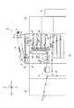
画像形成装置Gは、図1に示すように、プリントコントローラーg1、給紙ユニットg2、本体ユニットg3及び後処理装置g4を備えている。 As shown in FIG. 1, the image forming apparatus G includes a print controller g1, a sheet feeding unit g2, a main body unit g3, and a post-processing device g4.
プリントコントローラーg1は、ネットワーク上のコンピューター端末からPDL(Page Description Language)データを受信し、当該PDLデータをラスタライズ処理してビットマップ形式の画像データを生成する。
プリントコントローラーg1は、C(シアン)、M(マジェンタ)、Y(イエロー)及びK(黒)の色ごとに画像データを生成し、本体ユニットg3に出力する。
The print controller g1 receives page description language (PDL) data from a computer terminal on a network, and rasterizes the PDL data to generate bitmap image data.
The print controller g1 generates image data for each color of C (cyan), M (magenta), Y (yellow) and K (black), and outputs the image data to the main unit g3.
給紙ユニットg2は、大容量の給紙トレイを複数備えている。
給紙ユニットg2は、本体ユニットg3により指示された給紙トレイから本体ユニットg3へ用紙を搬送する。
The sheet feeding unit g2 includes a plurality of large-capacity sheet feeding trays.
The sheet feeding unit g2 conveys a sheet from the sheet feeding tray instructed by the main body unit g3 to the main body unit g3.
本体ユニットg3は、操作部3、表示部4、自動原稿搬送部61、スキャナー部6、画像形成部8、給紙トレイg31、読取部9、矯正部10等を備えている。
本体ユニットg3は、スキャナー部6により原稿用紙Dを読み取って得られた画像データ又はプリントコントローラーg1により生成された画像データに基づき、画像形成部8により用紙上に画像を形成する。本体ユニットg3は、画像形成された用紙を後処理装置g4へ搬送する。
The main body unit g3 includes an
The main body unit g3 forms an image on the sheet by the
後処理装置g4は、本体ユニットg3から搬送された用紙を後処理して排紙する。後処理としては、例えばステイプル処理、パンチ穴開け処理、折り処理、製本処理等が挙げられる。後処理は必須ではなく、後処理装置g4は、本体ユニットg3から指示された場合のみ実行する。後処理が無い場合、後処理装置g4は搬送された用紙をそのまま排紙する。 The post-processing device g4 post-processes and discharges the sheet conveyed from the main body unit g3. Examples of the post-processing include staple processing, punching processing, folding processing, bookbinding processing, and the like. The post-processing is not essential, and the post-processing device g4 is executed only when instructed by the main unit g3. If there is no post-processing, the post-processing device g4 discharges the conveyed sheet as it is.
本体ユニットg3は、図2に示すように、制御部1、記憶部2、操作部3、表示部4、通信部5、自動原稿搬送部61、スキャナー部6、画像処理装置7、画像形成部8、読取部9、コロ駆動部200、矯正部10を備えて構成されている。
As shown in FIG. 2, the
制御部1は、CPU、RAM等を備えている。制御部1は、記憶部2に記憶されているプログラムを読み出し、当該プログラムに従って画像形成装置Gの各部を制御する。
例えば、制御部1は、ジョブの設定に従い、給紙ユニットg2又は給紙トレイg31により用紙を給紙させる。また、制御部1は、画像処理装置7により画像データを補正及び画像処理させて、画像形成部8により画像を形成させる。ジョブの設定に後処理の設定が含まれる場合、制御部1は後処理装置g4に指示して後処理させる。
The
For example, the
記憶部2は、制御部1が読み取り可能なプログラム、ファイル等を記憶している。記憶部2としては、例えばハードディスク、ROM(Read Only Memory)等の記憶媒体を用いることができる。また、記憶部2は、印字位置測定用の基準画像を記憶している。
The
操作部3は、操作キーや表示部4と一体に構成されたタッチパネル等を備え、これらの操作に応じた操作信号を制御部1に出力する。ユーザーは、操作部3により、ジョブの設定、処理内容の変更等の指示を入力することができる。
表示部4は、LCD(Liquid Crystal Display)等であることができ、制御部1の指示に従って操作画面等を表示する。
通信部5は、制御部1からの指示に従い、ネットワーク上のコンピューター、例えばサーバー又は他の画像形成装置と通信する。
The
The
The
自動原稿搬送部61は、原稿用紙Dを載置する載置トレイや原稿用紙Dを搬送する機構及び搬送ローラー等を備えて構成され、原稿用紙Dを所定の搬送経路に搬送する。
スキャナー部6は、光源や反射鏡等の光学系を備えて構成され、所定の搬送経路を搬送された原稿用紙D又はプラテンガラスに載置された原稿用紙Dの画像を読み取って、R(赤)、G(緑)及びB(青)の色ごとの画像データを生成し、画像処理装置7に出力する。
The automatic
The
画像処理装置7は、スキャナー部6又はプリントコントローラーg1から入力された画像データを補正し、画像処理を施して、画像形成部8に出力する。
画像処理装置7は、図2に示すように、色変換部71、階調補正部72及び中間調処理部73を備えている。
The
As shown in FIG. 2, the
色変換部71は、スキャナー部6から出力されたR、G及びBの各色の画像データを色変換処理し、C、M、Y及びKの各色の画像データを出力する。
色変換部71は、色補正のため、プリントコントローラーg1から出力されたC、M、Y及びKの各色の画像データを色変換処理し、色補正されたC、M、Y及びKの各色の画像データを出力することもできる。
色変換部71は、色変換処理時、R、G及びBの各色の階調値に対して、色変換後のC、M、Y及びKの各色の階調値が定められたLUTを用いる。色変換部71は、色補正時、C、M、Y及びKの各色の階調値に対して、色補正後のC、M、Y及びKの階調値が定められたLUTを用いる。
The
The
The
階調補正部72は、色変換部71又はプリントコントローラーg1から出力された画像データの階調を補正する。
階調補正部72は、階調の補正時、画像の階調特性が目標の階調特性に一致するように、各階調値に対応する補正値が定められたLUTを用いる。階調補正部72は、階調補正用のLUTから、画像データの各画素の階調値に対応する補正値を得て、補正値からなる画像データを出力する。
The
At the time of tone correction, the
中間調処理部73は、階調補正部72から出力された画像データを中間調処理する。中間調処理は、例えばディザマトリクスを用いたスクリーン処理、誤差拡散処理等である。
中間調処理部73は、中間調処理後の画像データを画像形成部8に出力する。
The
The
画像形成部8は、画像処理装置7から出力された画像データに基づき、用紙上に画像を形成する。
画像形成部8は、図1に示すように、C、M、Y及びKの色ごとに、露光部81、感光体82及び現像部83を、4セット備えている。また、画像形成部8は、中間転写ベルト84、2次転写ローラー85、定着装置86及び反転機構87を備えている。
The
As illustrated in FIG. 1, the
露光部81は、発光素子としてLD(Laser Diode)を備えている。露光部81は、画像データに基づいてLDを駆動し、帯電する感光体82上にレーザー光を照射して露光する。現像部83は、帯電する現像ローラーにより感光体82上にトナーを供給し、露光により感光体82上に形成された静電潜像を現像する。
このようにして4つの感光体82上に各色のトナーで形成された画像は、各感光体82から中間転写ベルト84上に順次重ねて転写される。これにより、中間転写ベルト84上にカラー画像が形成される。中間転写ベルト84は、複数のローラーに巻き回された無端ベルトであり、各ローラーの回転に従って回転する。
The
The images formed with the toners of the respective colors on the four
2次転写ローラー85は、中間転写ベルト84上のカラー画像を、給紙ユニットg2又は給紙トレイg31から給紙された用紙上に転写する。定着装置86は、転写後の用紙を加熱及び加圧して定着処理する。
The
画像形成部8は、用紙の両面に画像を形成する場合、反転機構87により用紙の表裏を反転させ、もう一方の片面に対して画像を形成する。反転機構87は、通過する用紙の表裏を反転させて2次転写ローラー85による転写位置へと再度用紙を搬送する搬送経路を有している。
When forming an image on both sides of the sheet, the
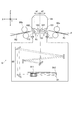
読取部9は、図1及び図3に示すように、搬送経路よりも下方に設けられ、読取部9よりも搬送方向上流側に設けられた上流搬送経路R1から搬送された用紙P上に形成された画像の読み取りを行う。読取部9により画像の読み取りが行われた用紙Pは、読取部9よりも搬送方向下流側に設けられた下流搬送経路R2から後処理装置g4へと搬送される。読取部9で画像の読み取りが行われる際、搬送経路上に設けられた複数の搬送ローラー(上流側搬送ローラー88a、下流側搬送ローラー88b等)により、用紙Pが所定の速度で読取位置Lを通過するように用紙搬送が行われる。
読取部9は、所定の読取位置Lで用紙P上に形成された画像の読み取りを行う光学式センサーとしてのCCD(Charge Coupled Device)91と、読取位置Lの像をCCD91に導くための光学系92と、読取位置Lを照らすLED(Light Emitting Diode)光源93と、等を備えて構成されている。
As shown in FIGS. 1 and 3, the
The
CCD91は、用紙Pの幅方向(Y方向)における全幅の範囲を読み取り可能なカラーラインセンサーである。CCD91は、CCD取付フレーム911により支持部材912を介して所定の位置に支持されている。
光学系92は、複数のミラーと、複数のレンズと、を備えて構成されている。
読取部9は、上記の構成を備えることにより、読取位置Lを通過する用紙Pの全幅に亘って用紙P上に形成された画像を順次読み取り可能となっている。
The
The
The
本実施形態では、印字位置測定用の基準画像K1は、図4に示すように、十字状の印であり、用紙Pの四隅にそれぞれ1つずつ形成される。制御部1は、読取部9により読み取られた基準画像K1に基づいて、用紙Pのエッジから近接する基準画像K1までの距離A1、B1(図4参照)を測定し、基準画像K1の実際の印字位置を算出する。そして、制御部1は、次回以降本来の印字位置に画像が形成されるように印字位置の調整を行う。
In the present embodiment, the reference image K1 for print position measurement is a cross-shaped mark as shown in FIG. 4 and is formed at each of four corners of the sheet P. The
また、読取部9の上方には、搬送経路を挟むようにして校正部94が設けられている。
校正部94は、画像の読み取りの際に行うシェーディング補正の補正値を決定するための白基準板を備えている。白基準板は、読取位置Lに設けられ、用紙Pの非通過時(例えば、用紙Pと用紙Pの合間等)に間隔を空けてCCD91による読み取りが行われる。
Further, a
The
校正部94の下面には、図3に示すように、読取位置Lを挟んで搬送方向上流側に上流ガイド部材101が、搬送方向下流側に下流ガイド部材102が、それぞれ設けられている。
この上流ガイド部材101及び下流ガイド部材102により、用紙Pの上方への移動を規制して、読取位置Lを通過させることができるようになっている。
On the lower surface of the
By the
読取部9の上面、即ち、用紙の搬送経路側の面には、図3に示すように、読取部9の読取位置Lよりも搬送方向上流側であって上流ガイド部材101と対向する位置に第1上流コロ(上流コロ)111が設けられ、読取位置Lよりも搬送方向下流側であって下流ガイド部材102と対向する位置に第1下流コロ(下流コロ)112が設けられている。第1上流コロ111及び第1下流コロ112は、それぞれ搬送方向と直交する回転軸に挿通され、回転軸を中心として回転可能となっている。
また、第1上流コロ111及び第1下流コロ112は、それぞれコロ駆動部200により上下動可能に構成されている。第1上流コロ111及び第1下流コロ112は、用紙P搬送時に上方に移動することで、用紙Pを上方に押し上げて校正部94の読取面に押し当てることができるようになっている。
On the upper surface of the
In addition, the first upstream roller 111 and the first
コロ駆動部200は、制御部11の制御により、用紙P搬送時に第1上流コロ111及び第1下流コロ112を上方に移動させることで、用紙Pを上方に押し上げて校正部94の読取面に押し当てる動作を行う。このとき、制御部11は、搬送される用紙の紙種(坪量)に基づいて、第1上流コロ111及び第1下流コロ112の高さが所定の高さとなるように、コロ駆動部200を制御する。具体的には、制御部11は、用紙の坪量が大きい場合には、第1上流コロ111及び第1下流コロ112の高さが相対的に低い高さとなるように、コロ駆動部200を制御する。一方、制御部11は、用紙の坪量が小さい場合には、第1上流コロ111及び第1下流コロ112の高さが相対的に高い高さとなるように、コロ駆動部200を制御する。
The
校正部94の上面側には、読取位置Lを挟んで搬送方向上流側であって第1上流コロ111の下流側に第2上流コロ121が、搬送方向下流側であって第1下流コロ112の上流側に第2下流コロ122が、それぞれ設けられている。第2上流コロ121及び第2下流コロ122は、それぞれ搬送方向と直交する回転軸に挿通され、回転軸を中心として回転可能となっている。
この第2上流コロ121及び第2下流コロ122により、用紙P上に形成された画像を読み取るための読取面が形成される。即ち、第2上流コロ121及び第2下流コロ122は、読取部9で画像を読み取る際の用紙高さの基準となっている。また、上記したように、用紙P搬送時には、第1上流コロ111及び第1下流コロ112を上方に移動させて用紙Pを校正部94の読取面(第2上流コロ121及び第2下流コロ122)に押し当てることで、画像を読み取る際の用紙高さを一定の高さに保つことができるようになっている。
On the upper surface side of the
The second
上流搬送経路R1は、搬送方向に対して上方に傾斜して設けられ、読取部9に搬送される用紙に対して上方への押圧力を加えることができるようになっている。下流搬送経路R2は、搬送方向に対して下方に傾斜して設けられ、読取部9より搬送される用紙に対して下方への押圧力を加えることができるようになっている。
The upstream transport path R1 is provided to be inclined upward with respect to the transport direction, and can apply an upward pressing force to the sheet transported to the
矯正部10は、定着処理された用紙の変形を矯正し、用紙面を平面化する。ここで、用紙は定着処理によって変形しやすく、基準画像の読取時に用紙を平面化する必要がある。従って、矯正部10は、図1に示すように、用紙の搬送方向において定着装置86と読取部9の間に配置されている。
The
本発明の画像読取装置は、少なくとも読取部9と、第1上流コロ111と、第1下流コロ112と、印字位置設定部としての制御部1と、を備えて構成される。
The image reading apparatus according to the present invention includes at least a
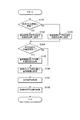
次に、本実施形態に係る画像形成装置Gの動作について、図5のフローチャートを参照して説明する。この動作は、制御部11が、ユーザーによる印字位置調整モードの選択操作を受け付けたことを契機として開始される。 Next, the operation of the image forming apparatus G according to the present embodiment will be described with reference to the flowchart of FIG. This operation is started when the control unit 11 receives a selection operation of the print position adjustment mode by the user.
まず、制御部1は、ユーザーにより予め設定された用紙の紙種設定を読み出して、搬送される用紙が厚紙であるか否かを判定する(ステップS101)。ここで、ユーザーにより予め設定される紙種は、「厚紙」、「通常紙(中斤量)」、「薄紙」である。なお、本実施形態では、坪量が40〜64g/m2の用紙を「薄紙」、65〜199g/m2の用紙を「通常紙」、200〜350g/m2の用紙を「厚紙」と定義する。
制御部1は、搬送される用紙が厚紙であると判定した場合(ステップS101:YES)、印字位置測定用の基準画像の印字位置を厚紙用の位置(厚紙用位置)に設定する(ステップS102)。
一方、制御部1は、搬送される用紙が厚紙でないと判定した場合(ステップS101:NO)、印字位置測定用の基準画像の印字位置をその他の用紙用の位置(他紙用位置)に設定する(ステップS103)。
First, the
When it is determined that the sheet to be conveyed is thick (step S101: YES), the
On the other hand, when determining that the sheet to be conveyed is not thick sheet (step S101: NO), the
本実施形態では、基準画像の印字位置は、用紙の先後端に衝撃が発生するタイミングと読取部9により基準画像が読み取られるタイミングとが重ならない位置に設定される。即ち、制御部1は、本発明の印字位置設定部として機能する。より具体的には、基準画像の印字位置は、用紙の先端から基準画像までの距離A1(図4参照)が、読取部9の読取位置から第1下流コロ112までの距離a1(図3参照)よりも短くなるように、且つ、用紙の後端から基準画像までの距離A2(図4参照)が、読取部9の読取位置から第1上流コロ111までの距離a2(図3参照)よりも短くなるように設定される。
In the present embodiment, the printing position of the reference image is set at a position where the timing at which an impact is generated at the front and rear end of the sheet and the timing at which the
ここで、厚紙用位置は、他紙用位置と比べ、基準画像の印字位置が用紙の内側寄りとなるように設定されている。これは、厚紙の場合、ベルト転写時や転写後の定着ローラー突入時、用紙後端のニップ抜け時等において、用紙のエッジに衝撃が発生しやすく転写ズレに繋がることから、基準画像がにじみやすくなり画像位置が正しく読み取れない虞があるからである。 Here, the position for heavy paper is set such that the printing position of the reference image is closer to the inside of the paper than the position for other paper. This is because, in the case of thick paper, at the time of belt transfer, when the fixing roller enters after the transfer, at the trailing edge of the paper at the time of nip loss, etc., an impact is easily generated at the edge of the paper, leading to transfer deviation. This is because there is a possibility that the image position can not be read correctly.
例えば、読取部9の読取位置Lから15mmの位置に第1下流コロ112が配置されている場合、用紙の坪量が200g/m2以上では印字位置を用紙のエッジから10mmの位置(厚紙用位置)に設定し(ステップS102参照)、200g/m2未満では印字位置を用紙のエッジから5mmの位置(他紙用位置)に設定する(ステップS103参照)。
For example, when the first
次に、制御部1は、ユーザーにより厚紙搬送時の基準画像の印字位置が手動で設定されたか否かを判定する(ステップS104)。
制御部1は、ユーザーにより厚紙搬送時の基準画像の印字位置が手動で設定されたと判定した場合(ステップS104:YES)、ステップS102で設定された基準画像の印字位置に手動設定を反映させる(ステップS105)。例えば、ユーザーにより厚紙搬送時の基準画像の印字位置が8mmに手動で設定されていた場合、印字位置の設定を、用紙のエッジから10mmの位置(厚紙用位置)から8mmの位置に変更する。
一方、制御部1は、ユーザーにより厚紙搬送時の基準画像の印字位置が手動で設定されていないと判定した場合(ステップS104:NO)、ステップS106へと移行する。
Next, the
When the
On the other hand, when the
次に、制御部1は、用紙の搬送を開始し、画像形成部8により、上記で設定された印字位置に基準画像を形成させる(ステップS106)。
次に、制御部1は、読取部9によりステップS106で用紙上に形成された基準画像が読み取られて得られた印字位置を取得する(ステップS107)。
次に、制御部1は、ステップS107で取得した印字位置に応じて画像形成条件を変更し、画像の印字位置を調整する(ステップS108)。
Next, the
Next, the
Next, the
以上のように、本実施形態に係る画像形成装置Gは、読取部9の用紙の搬送経路側の面であって、読取部9の読取位置よりも搬送方向上流側に設けられ、上下動可能に構成された上流コロ(第1上流コロ111)と、読取部9の用紙の搬送経路側の面であって、読取部9の読取位置よりも搬送方向下流側に設けられ、上下動可能に構成された下流コロ(第1下流コロ112)と、用紙の先後端に衝撃が発生するタイミングと読取部9により用紙上に形成された印字位置測定用の基準画像が読み取られるタイミングとが重ならない位置に、基準画像の印字位置を設定する印字位置設定部(制御部1)と、を備える。
従って、本実施形態に係る画像形成装置Gによれば、読取部9による画像読み取り時における衝撃の発生を抑制して用紙の速度変動を抑制することができるので、読取部9による画像位置の読取精度を向上させることが可能となり、画像の印字位置を正確に調整することができる。
As described above, the image forming apparatus G according to the present embodiment is a surface on the sheet conveyance path side of the
Therefore, according to the image forming apparatus G according to the present embodiment, it is possible to suppress the occurrence of the impact upon reading the image by the
また、本実施形態に係る画像形成装置Gによれば、印字位置設定部は、用紙の先端から基準画像までの距離が、読取部9の読取位置から下流コロまでの距離よりも短くなるように、且つ、用紙の後端から基準画像までの距離が、読取部9の読取位置から上流コロまでの距離よりも短くなるように、基準画像の印字位置を設定する。
従って、本実施形態に係る画像形成装置Gによれば、読取部9による画像読み取り時における用紙の先端と下流コロの衝突や用紙の後端のニップ抜け等に起因する衝撃の発生を抑制して用紙の速度変動を抑制することができるので、読取部9による画像位置の読取精度を向上させることが可能となり、画像の印字位置を正確に調整することができる。
Further, according to the image forming apparatus G according to the present embodiment, the printing position setting unit is configured such that the distance from the leading end of the sheet to the reference image is shorter than the distance from the reading position of the
Therefore, according to the image forming apparatus G according to the present embodiment, the occurrence of an impact caused by the collision of the leading end of the sheet and the downstream roller or the omission of the nip at the rear end of the sheet at the time of image reading by the
また、本実施形態に係る画像形成装置Gによれば、印字位置設定部は、画像形成条件に基づいて、基準画像の印字位置を設定する。ここで、画像形成条件とは、例えば、用紙の紙種や、用紙の画像印字領域等である。
例えば、本実施形態に係る画像形成装置Gによれば、印字位置設定部は、用紙の紙種に基づいて、基準画像の印字位置を設定する。具体的には、印字位置設定部は、搬送される用紙が厚紙である場合に、他紙と比べ、基準画像の印字位置を用紙の内側寄りとなるように設定する。
従って、本実施形態に係る画像形成装置Gによれば、用紙のエッジへの衝撃の影響を回避して画像の転写や定着を行うことができるので、基準画像のにじみを抑制することが可能となり、読取部9による画像位置の読取精度を向上させることができる。
Further, according to the image forming apparatus G according to the present embodiment, the print position setting unit sets the print position of the reference image based on the image forming condition. Here, the image forming conditions are, for example, the sheet type of the sheet, the image printing area of the sheet, and the like.
For example, according to the image forming apparatus G according to the present embodiment, the print position setting unit sets the print position of the reference image based on the sheet type of the sheet. Specifically, when the sheet to be conveyed is a thick sheet, the print position setting unit sets the print position of the reference image closer to the inner side of the sheet as compared to other sheets.
Therefore, according to the image forming apparatus G according to the present embodiment, since the image can be transferred and fixed while avoiding the influence of an impact on the edge of the sheet, it is possible to suppress the bleeding of the reference image. The reading accuracy of the image position by the
以上、本発明に係る実施形態に基づいて具体的に説明したが、本発明は上記実施形態に限定されるものではなく、その要旨を逸脱しない範囲で変更可能である。 As mentioned above, although it explained concretely based on the embodiment concerning the present invention, the present invention is not limited to the above-mentioned embodiment, and can be changed in the range which does not deviate from the gist.
例えば、上記実施形態では、搬送される用紙が厚紙である場合に、基準画像の印字位置を他紙と比べて用紙の内側寄りとなるように設定するようにしているが、これに限定されるものではない。即ち、用紙のエッジ近傍にて画像がにじみやすい紙種であればいかなる用紙であってもよく、例えば、搬送される用紙が再生紙、エンボス紙、風切紙等である場合に、基準画像の印字位置を他紙と比べて用紙の内側寄りとなるように設定するようにしてもよい。 For example, in the above embodiment, when the sheet to be conveyed is a thick sheet, the printing position of the reference image is set to be closer to the inner side of the sheet compared to other sheets, but is limited thereto It is not a thing. That is, any paper type may be used as long as the image is likely to bleed near the edge of the paper, for example, when the paper to be conveyed is recycled paper, embossed paper, wind-cut paper, etc., printing of the reference image The position may be set so as to be closer to the inner side of the sheet as compared to other sheets.
また、上記実施形態では、ユーザーにより厚紙搬送時の基準画像の印字位置が手動で設定された場合に、その手動設定を反映させるようにしているが、これに限定されるものではない。例えば、ユーザーにより厚紙搬送時の基準画像の印字位置が手動で設定された場合であっても、自動的に基準画像の印字位置を厚紙用位置(図5のステップS102参照)に設定するようにしてもよい。 Further, in the above embodiment, when the printing position of the reference image at the time of thick sheet conveyance is manually set by the user, the manual setting is reflected, but the present invention is not limited to this. For example, even if the printing position of the reference image at the time of thick sheet conveyance is manually set by the user, the printing position of the reference image is automatically set to the position for thick sheet (see step S102 in FIG. 5). May be
以上のように、印字位置設定部が、紙種が所定の紙種(例えば厚紙)であった場合に、自動的に又はユーザー操作による手動設定に基づいて、基準画像の印字位置を設定することで、状況に応じた印字位置の設定を行うことができるので、目的に適った印字位置の調整を行うことができる。 As described above, when the paper type is a predetermined paper type (for example, thick paper), the printing position setting unit sets the printing position of the reference image automatically or based on the manual setting by the user operation. Since the print position can be set according to the situation, the print position can be adjusted according to the purpose.
また、搬送される用紙の画像印字領域に基づいて、基準画像の印字位置を設定するようにしてもよい。より具体的には、搬送される用紙の画像印字領域が狭いほど、基準画像の印字位置を用紙の内側に設定するようにしてもよい。なお、画像印字領域は、例えば、用紙のサイズ、用紙に形成される画像のサイズ、印字倍率及び印字位置に基づいて算出される。 Further, the print position of the reference image may be set based on the image print area of the sheet to be conveyed. More specifically, the printing position of the reference image may be set to the inside of the sheet as the image printing area of the sheet to be conveyed is narrower. The image printing area is calculated based on, for example, the size of the sheet, the size of the image formed on the sheet, the printing magnification, and the printing position.
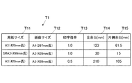
図6に、用紙のサイズ、用紙に形成される画像のサイズ及び印字倍率と余白との関係を示すテーブルT1の一例を示す。テーブルT1は、用紙サイズT11、画像サイズT12、印字倍率T13、搬送方向の全余白T14、搬送方向の片側余白T15のフィールドを有する。なお、図6では、画像を用紙のセンター位置に形成する例を示している。
テーブルT1の1番目のレコードからは、用紙サイズT11が「A3(420mm長)」、画像サイズT12が「A4(297mm長)」、印字倍率T13が「1.0」倍である場合に、搬送方向の全余白T14が「123mm」、搬送方向の片側余白T15が「61.5mm」である旨を読み取ることができる。また、2番目のレコードからは、用紙サイズT11が「SRA3(450mm長)」、画像サイズT12が「A3(420mm長)」、印字倍率T13が「1.0」倍である場合に、搬送方向の全余白T14が「30mm」、搬送方向の片側余白T15が「15mm」である旨を読み取ることができる。また、3番目のレコードからは、用紙サイズT11が「A3(420mm長)」、画像サイズT12が「A3(420mm長)」、印字倍率T13が「0.5」倍である場合に、搬送方向の全余白T14が「210mm」、搬送方向の片側余白T15が「105mm」である旨を読み取ることができる。
FIG. 6 shows an example of a table T1 showing the relationship between the size of a sheet, the size of an image formed on the sheet, and the print magnification and the margin. The table T1 has fields of paper size T11, image size T12, printing magnification T13, full margin T14 in the transport direction, and one-side margin T15 in the transport direction. FIG. 6 shows an example in which an image is formed at the center position of a sheet.
From the first record of the table T1, when the paper size T11 is "A3 (420 mm long)", the image size T12 is "A4 (297 mm long)", and the printing magnification T13 is "1.0" times, It can be read that the full margin T14 in the direction is "123 mm" and the one-side margin T15 in the transport direction is "61.5 mm". Also, from the second record, when the paper size T11 is "SRA3 (450 mm long)", the image size T12 is "A3 (420 mm long)", and the printing magnification T13 is "1.0" times, the transport direction It can be read that the total margin T14 of is 30 mm and the one-side margin T15 in the transport direction is 15 mm. Also, from the third record, when the paper size T11 is "A3 (420 mm long)", the image size T12 is "A3 (420 mm long)", and the print magnification T13 is "0.5" times, the transport direction It is possible to read that the total margin T14 of is “210 mm” and the one-side margin T15 in the transport direction is “105 mm”.
以上のように、印字位置設定部が、用紙の画像印字領域に基づいて、基準画像の印字位置を設定することで、形成される画像に応じた印字位置の設定を行うことができるので、より精度よく印字位置の調整を行うことができる。 As described above, the print position setting unit can set the print position according to the formed image by setting the print position of the reference image based on the image print area of the sheet. The printing position can be adjusted with high accuracy.
特に、印字位置設定部が、画像印字領域が狭いほど、基準画像の印字位置を用紙の内側に設定することで、形成される画像に適した印字位置の設定を行うことができるので、より精度よく印字位置の調整を行うことができる。 In particular, as the print position setting unit sets the print position of the reference image to the inside of the sheet as the image print area is narrower, the print position suitable for the formed image can be set. The print position can be adjusted well.
また、印字位置設定部が、用紙のサイズ、用紙に形成される画像のサイズ、印字倍率及び印字位置に基づいて画像印字領域を算出し、当該算出した画像印字領域に基づいて基準画像の印字位置を設定することで、画像印字領域を正確に抽出して印字位置の設定を行うことができるので、より精度よく印字位置の調整を行うことができる。 Further, the print position setting unit calculates the image print area based on the size of the sheet, the size of the image formed on the sheet, the print magnification, and the print position, and the print position of the reference image based on the calculated image print area. By setting the image printing area, it is possible to extract the image printing area accurately and set the printing position, so that the printing position can be adjusted more accurately.
また、上記実施形態では、搬送経路を挟んで上方に校正部94を、下方に読取部9を、それぞれ配置する構成を採用しているが、これに限定されるものではない。例えば、搬送経路を挟んで上方に読取部9を、下方に校正部94を、それぞれ配置する構成を採用するようにしてもよい。
In the above-described embodiment, the
また、上記実施形態では、読取部9及び校正部94をそれぞれ1つずつ配置する構成を採用しているが、これに限定されるものではない。例えば、読取部9及び校正部94をそれぞれ2つずつ配置する構成を採用するようにしてもよい。この場合、一方は、搬送経路を挟んで上方に校正部94を下方に読取部9をそれぞれ配置する構成を採用し、他方は、搬送経路を挟んで上方に読取部9を下方に校正部94をそれぞれ配置する構成を採用することで、片面ずつ画像を読み取ることができるので、一度の用紙搬送で用紙両面の画像を読み取ることができる。
Further, in the above embodiment, although the configuration in which the
その他、画像形成装置を構成する各装置の細部構成及び各装置の細部動作に関しても、本発明の趣旨を逸脱することのない範囲で適宜変更可能である。 In addition, the detailed configurations of the respective devices constituting the image forming apparatus and the detailed operations of the respective devices can be appropriately modified without departing from the scope of the present invention.
G 画像形成装置
1 制御部(印字位置設定部)
2 記憶部
3 操作部
4 表示部
8 画像形成部
88a 上流側搬送ローラー
88b 下流側搬送ローラー
9 読取部
94 校正部
101 上流ガイド部材
102 下流ガイド部材
111 第1上流コロ(上流コロ)
112 第1下流コロ(下流コロ)
121 第2上流コロ
122 第2下流コロ
R1 上流搬送経路
R2 下流搬送経路
G
112 1st downstream roller (downstream roller)
121 second
Claims (24)
前記読取部の読取位置よりも搬送方向下流側に設けられ、搬送される用紙を前記読取部の読取面に向けて押す下流側押部と、
用紙上に形成される前記基準画像の位置を自動的に設定するとともに、前記用紙上に画像を形成する画像形成部によって前記基準画像を設定された位置に形成させる制御部と、を備え、
前記制御部は、前記用紙の紙種毎に、前記画像形成部に形成させる前記基準画像の印字位置を異なる位置に設定するとともに、
前記用紙の先端から前記用紙上に形成される前記基準画像までの距離が、前記読取部の読取位置から前記下流側押部までの距離よりも短いことを特徴とする画像読取装置。 In an image reading apparatus including a reading unit that reads a reference image formed on a conveyed sheet in order to adjust the print position of the image.
A downstream-side pressing unit which is provided on the downstream side of the reading position of the reading unit in the conveyance direction, and presses a sheet to be conveyed toward the reading surface of the reading unit;
A control unit configured to automatically set the position of the reference image formed on a sheet, and to form the reference image at a set position by an image forming unit that forms an image on the sheet;
The control unit sets the printing position of the reference image to be formed in the image forming unit to a different position for each sheet type of the sheet.
Image reader distance from the tip of the paper to the reference image formed on the sheet, characterized in that not shorter than the distance to the downstream side pressing portion from the reading position of the reading unit.
前記読取部の読取位置よりも搬送方向上流側に設けられ、搬送される用紙を前記読取部の読取面に向けて押す上流側押部と、
用紙上に形成される前記基準画像の位置を自動的に設定するとともに、前記用紙上に画像を形成する画像形成部によって前記基準画像を設定された位置に形成させる制御部と、を備え、
前記制御部は、前記用紙の紙種毎に、前記画像形成部に形成させる前記基準画像の印字位置を異なる位置に設定するとともに、
前記用紙の後端から前記用紙上に形成される前記基準画像までの距離が、前記読取部の読取位置から前記上流側押部までの距離よりも短いことを特徴とする画像読取装置。 In an image reading apparatus including a reading unit that reads a reference image formed on a conveyed sheet in order to adjust the print position of the image.
An upstream-side pressing unit provided on the upstream side in the transport direction with respect to the reading position of the reading unit and pressing a sheet to be transported toward the reading surface of the reading unit;
A control unit configured to automatically set the position of the reference image formed on a sheet, and to form the reference image at a set position by an image forming unit that forms an image on the sheet;
The control unit sets the printing position of the reference image to be formed in the image forming unit to a different position for each sheet type of the sheet.
Image reader distance from the rear end of the paper to the reference image formed on the sheet, characterized in that not shorter than the distance to the upstream pressing portion from the reading position of the reading unit.
前記読取部の読取位置よりも搬送方向下流側に設けられ、搬送される用紙を前記読取部の読取面に向けて押す下流側押部と、A downstream-side pressing unit which is provided on the downstream side of the reading position of the reading unit in the conveyance direction, and presses a sheet to be conveyed toward the reading surface of the reading unit;
用紙上に形成される前記基準画像の位置を自動的に設定するとともに、前記用紙上に画像を形成する画像形成部によって前記基準画像を設定された位置に形成させる制御部と、を備え、A control unit configured to automatically set the position of the reference image formed on a sheet, and to form the reference image at a set position by an image forming unit that forms an image on the sheet;
前記制御部は、前記用紙のサイズ、前記用紙に形成される画像のサイズ、印字倍率及び印字位置に応じて前記基準画像の印字位置を異なる位置に設定するとともに、The control unit sets the print position of the reference image at different positions according to the size of the sheet, the size of the image formed on the sheet, the print magnification, and the print position.
前記用紙の先端から前記用紙上に形成される前記基準画像までの距離が、前記読取部の読取位置から前記下流側押部までの距離よりも短いことを特徴とする画像読取装置。An image reading apparatus, wherein a distance from a leading end of the sheet to the reference image formed on the sheet is shorter than a distance from a reading position of the reading section to the downstream side pressing section.
前記読取部の読取位置よりも搬送方向上流側に設けられ、搬送される用紙を前記読取部の読取面に向けて押す上流側押部と、An upstream-side pressing unit provided on the upstream side in the transport direction with respect to the reading position of the reading unit and pressing a sheet to be transported toward the reading surface of the reading unit;
用紙上に形成される前記基準画像の位置を自動的に設定するとともに、前記用紙上に画像を形成する画像形成部によって前記基準画像を設定された位置に形成させる制御部と、を備え、A control unit configured to automatically set the position of the reference image formed on a sheet, and to form the reference image at a set position by an image forming unit that forms an image on the sheet;
前記制御部は、前記用紙のサイズ、前記用紙に形成される画像のサイズ、印字倍率及び印字位置に応じて前記基準画像の印字位置を異なる位置に設定するとともに、The control unit sets the print position of the reference image at different positions according to the size of the sheet, the size of the image formed on the sheet, the print magnification, and the print position.
前記用紙の後端から前記用紙上に形成される前記基準画像までの距離が、前記読取部の読取位置から前記上流側押部までの距離よりも短いことを特徴とする画像読取装置。An image reading device characterized in that a distance from a rear end of the sheet to the reference image formed on the sheet is shorter than a distance from a reading position of the reading portion to the upstream pressing portion.
前記第2の種類の用紙における前記基準画像の印字位置は、前記第1の種類の用紙における前記基準画像の印字位置よりも、用紙の内側寄りとなるように設定されることを特徴とする請求項1又は2に記載の画像読取装置。 It is possible to transport a first type of sheet and a second type of sheet having a larger basis weight than the first type of sheet,
The printing position of the reference image on the second type of paper is set to be closer to the inner side of the printing position of the reference image on the first type of paper. An image reading apparatus according to claim 1 or 2 .
画像の印字位置の調整を行うため、前記画像形成部により用紙上に形成された基準画像を読み取る読取部と、
前記読取部の読取位置よりも搬送方向下流側に設けられ、搬送される用紙を前記読取部の読取面に向けて押す下流側押部と、
用紙上に形成される前記基準画像の位置を自動的に設定するとともに、前記画像形成部に前記基準画像を設定された位置に形成させる制御部と、を備え、
前記制御部は、前記用紙の紙種毎に、前記画像形成部に形成させる前記基準画像の印字位置を異なる位置に設定するとともに、
前記用紙の先端から前記用紙上に形成される前記基準画像までの距離が、前記読取部の読取位置から前記下流側押部までの距離よりも短いことを特徴とする画像形成装置。 An image forming unit that forms an image based on image data;
A reading unit that reads a reference image formed on a sheet by the image forming unit in order to adjust the print position of the image;
A downstream-side pressing unit which is provided on the downstream side of the reading position of the reading unit in the conveyance direction, and presses a sheet to be conveyed toward the reading surface of the reading unit;
A control unit that automatically sets the position of the reference image formed on a sheet and causes the image forming unit to form the reference image at the set position;
The control unit sets the printing position of the reference image to be formed in the image forming unit to a different position for each sheet type of the sheet.
Image forming apparatus the distance from the tip of the paper to the reference image formed on the sheet, characterized in that not shorter than the distance to the downstream side pressing portion from the reading position of the reading unit.
画像の印字位置の調整を行うため、前記画像形成部により用紙上に形成された基準画像を読み取る読取部と、
前記読取部の読取位置よりも搬送方向上流側に設けられ、搬送される用紙を前記読取部の読取面に向けて押す上流側押部と、
用紙上に形成される前記基準画像の位置を自動的に設定するとともに、前記画像形成部に前記基準画像を設定された位置に形成させる制御部と、を備え、
前記制御部は、前記用紙の紙種毎に、前記画像形成部に形成させる前記基準画像の印字位置を異なる位置に設定するとともに、
前記用紙の後端から前記用紙上に形成される前記基準画像までの距離が、前記読取部の読取位置から前記上流側押部までの距離よりも短いことを特徴とする画像形成装置。 An image forming unit that forms an image based on image data;
A reading unit that reads a reference image formed on a sheet by the image forming unit in order to adjust the print position of the image;
An upstream-side pressing unit provided on the upstream side in the transport direction with respect to the reading position of the reading unit and pressing a sheet to be transported toward the reading surface of the reading unit;
A control unit that automatically sets the position of the reference image formed on a sheet and causes the image forming unit to form the reference image at the set position;
The control unit sets the printing position of the reference image to be formed in the image forming unit to a different position for each sheet type of the sheet.
Image forming apparatus the distance from the rear end of the paper to the reference image formed on the sheet, characterized in that not shorter than the distance to the upstream pressing portion from the reading position of the reading unit.
画像の印字位置の調整を行うため、前記画像形成部により用紙上に形成された基準画像を読み取る読取部と、A reading unit that reads a reference image formed on a sheet by the image forming unit in order to adjust the print position of the image;
前記読取部の読取位置よりも搬送方向下流側に設けられ、搬送される用紙を前記読取部の読取面に向けて押す下流側押部と、A downstream-side pressing unit which is provided on the downstream side of the reading position of the reading unit in the conveyance direction, and presses a sheet to be conveyed toward the reading surface of the reading unit;
用紙上に形成される前記基準画像の位置を自動的に設定するとともに、前記画像形成部に前記基準画像を設定された位置に形成させる制御部と、を備え、A control unit that automatically sets the position of the reference image formed on a sheet and causes the image forming unit to form the reference image at the set position;
前記制御部は、前記用紙のサイズ、前記用紙に形成される画像のサイズ、印字倍率及び印字位置に応じて前記基準画像の印字位置を異なる位置に設定するとともに、The control unit sets the print position of the reference image at different positions according to the size of the sheet, the size of the image formed on the sheet, the print magnification, and the print position.
前記用紙の先端から前記用紙上に形成される前記基準画像までの距離が、前記読取部の読取位置から前記下流側押部までの距離よりも短いことを特徴とする画像形成装置。2. The image forming apparatus according to claim 1, wherein a distance from a leading end of the sheet to the reference image formed on the sheet is shorter than a distance from a reading position of the reading unit to the downstream side pressing unit.
画像の印字位置の調整を行うため、前記画像形成部により用紙上に形成された基準画像を読み取る読取部と、A reading unit that reads a reference image formed on a sheet by the image forming unit in order to adjust the print position of the image;
前記読取部の読取位置よりも搬送方向上流側に設けられ、搬送される用紙を前記読取部の読取面に向けて押す上流側押部と、An upstream-side pressing unit provided on the upstream side in the transport direction with respect to the reading position of the reading unit and pressing a sheet to be transported toward the reading surface of the reading unit;
用紙上に形成される前記基準画像の位置を自動的に設定するとともに、前記画像形成部に前記基準画像を設定された位置に形成させる制御部と、を備え、A control unit that automatically sets the position of the reference image formed on a sheet and causes the image forming unit to form the reference image at the set position;
前記制御部は、前記用紙のサイズ、前記用紙に形成される画像のサイズ、印字倍率及び印字位置に応じて前記基準画像の印字位置を異なる位置に設定するとともに、The control unit sets the print position of the reference image at different positions according to the size of the sheet, the size of the image formed on the sheet, the print magnification, and the print position.
前記用紙の後端から前記用紙上に形成される前記基準画像までの距離が、前記読取部の読取位置から前記上流側押部までの距離よりも短いことを特徴とする画像形成装置。2. The image forming apparatus according to claim 1, wherein a distance from a rear end of the sheet to the reference image formed on the sheet is shorter than a distance from a reading position of the reading section to the upstream pressing section.
前記第2の種類の用紙における前記基準画像の印字位置は、前記第1の種類の用紙における前記基準画像の印字位置よりも、用紙の内側寄りとなるように設定されることを特徴とする請求項13又は14に記載の画像形成装置。The printing position of the reference image on the second type of paper is set to be closer to the inner side of the printing position of the reference image on the first type of paper. Item 15. An image forming apparatus according to item 13 or 14.
Priority Applications (1)
| Application Number | Priority Date | Filing Date | Title |
|---|---|---|---|
| JP2016205611A JP6544334B2 (en) | 2016-10-20 | 2016-10-20 | Image reading apparatus and image forming apparatus |
Applications Claiming Priority (1)
| Application Number | Priority Date | Filing Date | Title |
|---|---|---|---|
| JP2016205611A JP6544334B2 (en) | 2016-10-20 | 2016-10-20 | Image reading apparatus and image forming apparatus |
Related Child Applications (1)
| Application Number | Title | Priority Date | Filing Date |
|---|---|---|---|
| JP2019087560A Division JP6860036B2 (en) | 2019-05-07 | 2019-05-07 | Image reader and image forming device |
Publications (3)
| Publication Number | Publication Date |
|---|---|
| JP2018067813A JP2018067813A (en) | 2018-04-26 |
| JP2018067813A5 JP2018067813A5 (en) | 2019-03-14 |
| JP6544334B2 true JP6544334B2 (en) | 2019-07-17 |
Family
ID=62087369
Family Applications (1)
| Application Number | Title | Priority Date | Filing Date |
|---|---|---|---|
| JP2016205611A Active JP6544334B2 (en) | 2016-10-20 | 2016-10-20 | Image reading apparatus and image forming apparatus |
Country Status (1)
| Country | Link |
|---|---|
| JP (1) | JP6544334B2 (en) |
Families Citing this family (1)
| Publication number | Priority date | Publication date | Assignee | Title |
|---|---|---|---|---|
| JP2020088704A (en) * | 2018-11-29 | 2020-06-04 | コニカミノルタ株式会社 | Image reading apparatus and image formation apparatus |
Family Cites Families (4)
| Publication number | Priority date | Publication date | Assignee | Title |
|---|---|---|---|---|
| JP6044768B2 (en) * | 2012-12-06 | 2016-12-14 | コニカミノルタ株式会社 | Image reading device |
| JP6119425B2 (en) * | 2013-05-28 | 2017-04-26 | コニカミノルタ株式会社 | Image forming apparatus and alignment method |
| JP6323191B2 (en) * | 2014-06-12 | 2018-05-16 | コニカミノルタ株式会社 | Image reading apparatus and image forming apparatus |
| JP6168081B2 (en) * | 2015-02-26 | 2017-07-26 | コニカミノルタ株式会社 | Image forming system, reading apparatus, and image forming apparatus |
-
2016
- 2016-10-20 JP JP2016205611A patent/JP6544334B2/en active Active
Also Published As
| Publication number | Publication date |
|---|---|
| JP2018067813A (en) | 2018-04-26 |
Similar Documents
| Publication | Publication Date | Title |
|---|---|---|
| US9733602B2 (en) | Image forming apparatus capable of performing duplex alignment without producing a waste sheet | |
| JP6323191B2 (en) | Image reading apparatus and image forming apparatus | |
| JP6119425B2 (en) | Image forming apparatus and alignment method | |
| US10200565B2 (en) | Image forming system and reading device | |
| US20120019852A1 (en) | Printing apparatus, method for controlling print quality, and storage medium storing instructions for same | |
| US9307097B2 (en) | Image forming apparatus | |
| US8783683B2 (en) | Image forming apparatus and image forming system | |
| JP7383431B2 (en) | Image forming device | |
| JP6357862B2 (en) | Image reading apparatus and image forming apparatus | |
| JP6544334B2 (en) | Image reading apparatus and image forming apparatus | |
| JP6094383B2 (en) | Image forming apparatus and sheet deformation correcting method | |
| JP7167199B2 (en) | Image reading device and image forming device | |
| JP6841360B2 (en) | Image forming device and image forming system | |
| JP6860036B2 (en) | Image reader and image forming device | |
| US20200177759A1 (en) | Image reading device and image forming apparatus | |
| JP2018142845A (en) | Image reading device and image forming apparatus | |
| JP2018065660A (en) | Image forming apparatus | |
| JP6766537B2 (en) | Reader and image formation system | |
| JP6248793B2 (en) | Image reading apparatus and image forming apparatus | |
| JP7006825B2 (en) | Image forming device and image forming system | |
| JP7092252B2 (en) | Image forming device and image forming system | |
| JP6923096B2 (en) | Image forming device and image forming system | |
| JP2019097029A (en) | Image forming device | |
| US11483450B2 (en) | Image forming apparatus and image reading apparatus | |
| JP6531771B2 (en) | Image reading apparatus and image forming apparatus |
Legal Events
| Date | Code | Title | Description |
|---|---|---|---|
| A621 | Written request for application examination |
Free format text: JAPANESE INTERMEDIATE CODE: A621 Effective date: 20181214 |
|
| A521 | Written amendment |
Free format text: JAPANESE INTERMEDIATE CODE: A523 Effective date: 20190131 |
|
| A131 | Notification of reasons for refusal |
Free format text: JAPANESE INTERMEDIATE CODE: A131 Effective date: 20190226 |
|
| A521 | Written amendment |
Free format text: JAPANESE INTERMEDIATE CODE: A523 Effective date: 20190507 |
|
| TRDD | Decision of grant or rejection written | ||
| A01 | Written decision to grant a patent or to grant a registration (utility model) |
Free format text: JAPANESE INTERMEDIATE CODE: A01 Effective date: 20190521 |
|
| A61 | First payment of annual fees (during grant procedure) |
Free format text: JAPANESE INTERMEDIATE CODE: A61 Effective date: 20190603 |
|
| R150 | Certificate of patent or registration of utility model |
Ref document number: 6544334 Country of ref document: JP Free format text: JAPANESE INTERMEDIATE CODE: R150 |