JP6531771B2 - Image reading apparatus and image forming apparatus - Google Patents
Image reading apparatus and image forming apparatus Download PDFInfo
- Publication number
- JP6531771B2 JP6531771B2 JP2017062802A JP2017062802A JP6531771B2 JP 6531771 B2 JP6531771 B2 JP 6531771B2 JP 2017062802 A JP2017062802 A JP 2017062802A JP 2017062802 A JP2017062802 A JP 2017062802A JP 6531771 B2 JP6531771 B2 JP 6531771B2
- Authority
- JP
- Japan
- Prior art keywords
- unit
- image
- sheet
- conveyance
- reading
- Prior art date
- Legal status (The legal status is an assumption and is not a legal conclusion. Google has not performed a legal analysis and makes no representation as to the accuracy of the status listed.)
- Active
Links
Images


Classifications
-
- H—ELECTRICITY
- H04—ELECTRIC COMMUNICATION TECHNIQUE
- H04N—PICTORIAL COMMUNICATION, e.g. TELEVISION
- H04N1/00—Scanning, transmission or reproduction of documents or the like, e.g. facsimile transmission; Details thereof
- H04N1/04—Scanning arrangements, i.e. arrangements for the displacement of active reading or reproducing elements relative to the original or reproducing medium, or vice versa
- H04N1/12—Scanning arrangements, i.e. arrangements for the displacement of active reading or reproducing elements relative to the original or reproducing medium, or vice versa using the sheet-feed movement or the medium-advance or the drum-rotation movement as the slow scanning component, e.g. arrangements for the main-scanning
- H04N1/126—Arrangements for the main scanning
- H04N1/1275—Arrangements for the main scanning using a solid-state deflector, e.g. an acousto-optic deflector or a semiconductor waveguide device
-
- G—PHYSICS
- G03—PHOTOGRAPHY; CINEMATOGRAPHY; ANALOGOUS TECHNIQUES USING WAVES OTHER THAN OPTICAL WAVES; ELECTROGRAPHY; HOLOGRAPHY
- G03G—ELECTROGRAPHY; ELECTROPHOTOGRAPHY; MAGNETOGRAPHY
- G03G15/00—Apparatus for electrographic processes using a charge pattern
- G03G15/50—Machine control of apparatus for electrographic processes using a charge pattern, e.g. regulating differents parts of the machine, multimode copiers, microprocessor control
- G03G15/5062—Machine control of apparatus for electrographic processes using a charge pattern, e.g. regulating differents parts of the machine, multimode copiers, microprocessor control by measuring the characteristics of an image on the copy material
-
- H—ELECTRICITY
- H04—ELECTRIC COMMUNICATION TECHNIQUE
- H04N—PICTORIAL COMMUNICATION, e.g. TELEVISION
- H04N1/00—Scanning, transmission or reproduction of documents or the like, e.g. facsimile transmission; Details thereof
- H04N1/00519—Constructional details not otherwise provided for, e.g. housings, covers
- H04N1/00549—Counter-measures for mechanical vibration not otherwise provided for
-
- H—ELECTRICITY
- H04—ELECTRIC COMMUNICATION TECHNIQUE
- H04N—PICTORIAL COMMUNICATION, e.g. TELEVISION
- H04N1/00—Scanning, transmission or reproduction of documents or the like, e.g. facsimile transmission; Details thereof
- H04N1/00976—Arrangements for regulating environment, e.g. removing static electricity
- H04N1/00978—Temperature control
- H04N1/00981—Temperature control by forced convection, e.g. using fans
-
- H—ELECTRICITY
- H04—ELECTRIC COMMUNICATION TECHNIQUE
- H04N—PICTORIAL COMMUNICATION, e.g. TELEVISION
- H04N1/00—Scanning, transmission or reproduction of documents or the like, e.g. facsimile transmission; Details thereof
- H04N1/024—Details of scanning heads ; Means for illuminating the original
- H04N1/028—Details of scanning heads ; Means for illuminating the original for picture information pick-up
- H04N1/02815—Means for illuminating the original, not specific to a particular type of pick-up head
- H04N1/0282—Using a single or a few point light sources, e.g. a laser diode
- H04N1/0283—Using a single or a few point light sources, e.g. a laser diode in combination with a light deflecting element, e.g. a rotating mirror
-
- H—ELECTRICITY
- H04—ELECTRIC COMMUNICATION TECHNIQUE
- H04N—PICTORIAL COMMUNICATION, e.g. TELEVISION
- H04N1/00—Scanning, transmission or reproduction of documents or the like, e.g. facsimile transmission; Details thereof
- H04N1/04—Scanning arrangements, i.e. arrangements for the displacement of active reading or reproducing elements relative to the original or reproducing medium, or vice versa
- H04N1/12—Scanning arrangements, i.e. arrangements for the displacement of active reading or reproducing elements relative to the original or reproducing medium, or vice versa using the sheet-feed movement or the medium-advance or the drum-rotation movement as the slow scanning component, e.g. arrangements for the main-scanning
- H04N1/121—Feeding arrangements
-
- H—ELECTRICITY
- H04—ELECTRIC COMMUNICATION TECHNIQUE
- H04N—PICTORIAL COMMUNICATION, e.g. TELEVISION
- H04N1/00—Scanning, transmission or reproduction of documents or the like, e.g. facsimile transmission; Details thereof
- H04N1/40—Picture signal circuits
- H04N1/40056—Circuits for driving or energising particular reading heads or original illumination means
-
- H—ELECTRICITY
- H04—ELECTRIC COMMUNICATION TECHNIQUE
- H04N—PICTORIAL COMMUNICATION, e.g. TELEVISION
- H04N1/00—Scanning, transmission or reproduction of documents or the like, e.g. facsimile transmission; Details thereof
- H04N1/46—Colour picture communication systems
- H04N1/52—Circuits or arrangements for halftone screening
-
- H—ELECTRICITY
- H04—ELECTRIC COMMUNICATION TECHNIQUE
- H04N—PICTORIAL COMMUNICATION, e.g. TELEVISION
- H04N2201/00—Indexing scheme relating to scanning, transmission or reproduction of documents or the like, and to details thereof
- H04N2201/0077—Types of the still picture apparatus
- H04N2201/0094—Multifunctional device, i.e. a device capable of all of reading, reproducing, copying, facsimile transception, file transception
Landscapes
- Engineering & Computer Science (AREA)
- Multimedia (AREA)
- Signal Processing (AREA)
- Physics & Mathematics (AREA)
- General Physics & Mathematics (AREA)
- Microelectronics & Electronic Packaging (AREA)
- Environmental & Geological Engineering (AREA)
- Optics & Photonics (AREA)
- Facsimile Scanning Arrangements (AREA)
- Facsimiles In General (AREA)
- Exposure Or Original Feeding In Electrophotography (AREA)
- Optical Systems Of Projection Type Copiers (AREA)
- Light Sources And Details Of Projection-Printing Devices (AREA)
Description
本発明は、画像読取装置及び当該画像読取装置を備える画像形成装置に関する。 The present invention relates to an image reading apparatus and an image forming apparatus provided with the image reading apparatus.
従来、電子写真方式の画像形成装置は、用紙上に画質調整用の基準画像を形成し、読取部により当該基準画像を読み取って得られた読取値に応じて画像形成条件等を変更し、画質が一定となるように調整している。 Conventionally, an electrophotographic image forming apparatus forms a reference image for image quality adjustment on a sheet, changes an image forming condition and the like according to a read value obtained by reading the reference image by a reading unit, Is adjusted to be constant.
読取部には、イメージセンサー(CCD)、用紙を照らす照明部(LED)、照明部から用紙に照らされた光をイメージセンサーに結像するための光学系(ミラー、レンズ等)が設けられている。
読取部のイメージセンサーやミラーに振動が伝わると、読み取った画像が波打ったり、読み取る位置が変動したりしてしまうため、用紙上に形成された画像を正確に読み取ることができないという課題がある。
The reading unit is provided with an image sensor (CCD), an illumination unit (LED) that illuminates the sheet, and an optical system (mirror, lens, etc.) for imaging light illuminated from the illumination unit onto the sheet on the image sensor There is.
If vibration is transmitted to the image sensor or mirror of the reading unit, the read image may be wavy or the reading position may be changed, so that there is a problem that the image formed on the sheet can not be read accurately. .
読取部の振動源としては、「用紙先端の搬送ガイド等への衝突」、「搬送ローラーへの用紙の突入衝撃及び搬送ローラーから用紙が抜ける衝撃」、「搬送ローラーを駆動するモーター」、「機内冷却用のファンモーター」が挙げられる。
「用紙先端の搬送ガイド等への衝突」と「搬送ローラーへの用紙の突入衝撃及び搬送ローラーから用紙が抜ける衝撃」とについては、用紙の物性(例えば、坪量、剛度等)や用紙サイズ、搬送速度により、振動の程度が大きく変化する。ただし、生産性を考慮すると、搬送速度は速いほどよく、用紙の種類も幅広く使用可能であることが望ましい。
As the vibration source of the reading unit, "collision of the leading end of the sheet to the conveyance guide etc.", "a rush impact of the sheet to the conveyance roller and an impact that the sheet comes off from the conveyance roller", "a motor for driving the conveyance roller" There is a fan motor for cooling.
For "collision of the leading edge of the sheet to the conveyance guide etc." and "impact impact of the sheet on the conveyance roller and the impact of the sheet coming off the conveyance roller", physical properties of the sheet (for example, basis weight, stiffness etc.) and sheet size The degree of vibration changes greatly depending on the transport speed. However, in consideration of productivity, it is preferable that the transport speed be as high as possible, and that the type of paper can be widely used.
そこで、搬送速度が速く且つ厚紙を搬送する場合であっても極力振動を発生させないよう、搬送経路を直線で構成することで、用紙と搬送ガイドとの衝突による振動を低減することができる。また、搬送経路を直線で構成することで、用紙を搬送ローラーで搬送する際の圧接力を小さくすることができるため、搬送ローラーを駆動するモーターに掛かる負荷も小さくなり、振動を抑制することができる。 Therefore, the vibration caused by the collision between the sheet and the conveyance guide can be reduced by configuring the conveyance path as a straight line so that the conveyance speed is high and vibrations are not generated as much as possible even when the thick paper is conveyed. In addition, by configuring the transport path as a straight line, the pressure contact force when transporting the sheet by the transport roller can be reduced, so the load on the motor for driving the transport roller is also reduced, and the vibration can be suppressed. it can.
しかしながら、従来の画像形成装置は、読取部の一部が用紙の搬送経路を構成している(具体的には、読取部の底面に搬送ガイド面が設けられている)ため、読取部と用紙との接触による振動を防ぐことができない。そのため、読取部と他の振動源との接触を極力避けるようにして、読取部の読取精度を確保する必要がある。 However, in the conventional image forming apparatus, a part of the reading unit constitutes a sheet conveyance path (specifically, the conveyance guide surface is provided on the bottom surface of the reading unit). Vibration due to contact with can not be prevented. Therefore, it is necessary to secure the reading accuracy of the reading unit by avoiding contact between the reading unit and another vibration source as much as possible.
ところで、読取部には、LEDやハロゲンランプなどの光源を備える照明部が設けられている。照明部は、発熱があると照度が安定しないという課題がある。そのため、冷却ファンにより光源を冷却する必要がある。
そこで、読取部の筐体に隔壁を設けて2つの区画を形成し、一方に冷却ファンを設置する構成が開示されている(例えば、特許文献1参照)。
By the way, the reading unit is provided with a lighting unit provided with a light source such as an LED or a halogen lamp. The lighting unit has a problem that the illuminance is not stable when heat is generated. Therefore, the light source needs to be cooled by the cooling fan.
Therefore, a configuration is disclosed in which a partition is provided in a housing of a reading unit to form two sections, and a cooling fan is installed in one of the sections (for example, see Patent Document 1).
ところで、冷却ファンは、特許文献1記載の技術のように、照明部を備える読取部の筐体に固定すると、より近くで照明部を冷却することができる。
しかしながら、振動源を有する冷却ファンを読取部の筐体に固定する構成では、ファンの振動が読取部の内部に伝達するという課題が発生する。このような課題は、冷却ファンに限らず、冷却部が振動源を有する構成であるときに発生する。例えば、振動源となるポンプを用いて水を循環させることで対象物を冷却する水冷装置を用いる場合においても、ポンプの振動が読取部の内部に伝達してしまう。
By the way, when the cooling fan is fixed to the housing of the reading unit including the lighting unit as in the technology described in Patent Document 1, the lighting unit can be cooled closer.
However, in the configuration in which the cooling fan having the vibration source is fixed to the housing of the reading unit, a problem occurs that the vibration of the fan is transmitted to the inside of the reading unit. Such a problem occurs when the cooling unit is configured to have a vibration source as well as the cooling fan. For example, even in the case of using a water-cooling device that cools an object by circulating water using a pump serving as a vibration source, the vibration of the pump is transmitted to the inside of the reading unit.
また、冷却ファンや水冷装置などの振動源を有する冷却部を、防振部材を介して読取部の筐体に固定する構成も考えられるが、部品点数が増大してコストアップするという課題がある。
また、ミラーやCCD等、読取部を構成する部品を、防振部材を介して固定する構成も考えられるが、部品点数が増大してコストアップする上、ミラーやCCD等の位置精度を確保することが困難である。
Although a cooling unit having a vibration source such as a cooling fan or a water cooling device may be fixed to the housing of the reading unit via a vibration isolation member, there is a problem that the number of parts increases and the cost increases. .
In addition, although it is conceivable to fix components that constitute the reading unit, such as mirrors and CCDs, via a vibration-proofing member, the number of components is increased to increase the cost, and position accuracy of the mirrors and CCDs is ensured. It is difficult.
本発明は、照明部の照度を安定させつつ、用紙上に形成された画像を正確に読み取ることが可能な画像読取装置及び当該画像読取装置を備える画像形成装置を提供することを目的とする。 An object of the present invention is to provide an image reading apparatus capable of accurately reading an image formed on a sheet while stabilizing the illuminance of the illumination unit, and an image forming apparatus provided with the image reading apparatus.
請求項1に記載の発明は、上記目的を達成するためになされたものであり、
画像読取装置において、
用紙上に形成された画像を所定の読取位置で読み取る読取部と、
前記画像が形成された用紙を前記読取位置を通過するように搬送する搬送部と、
前記読取部内に固定され、前記搬送部により前記読取位置に搬送された用紙を照明する照明部と、
振動源を有し、前記照明部を冷却する冷却部と、
筐体と、
前記読取部及び前記筐体を個別に保持する骨格と、
を備え、
前記冷却部は、前記筐体に保持されていることを特徴とする。
請求項2に記載の発明は、請求項1に記載の画像読取装置において、
前記筐体は、前記搬送部と、前記搬送部を駆動する搬送駆動部と、を保持することを特徴とする。
The invention according to claim 1 is made to achieve the above object,
In the image reader,
A reading unit that reads an image formed on a sheet at a predetermined reading position;
A conveyance unit configured to convey the sheet on which the image is formed so as to pass the reading position;
An illumination unit which is fixed in the reading unit and illuminates the sheet conveyed to the reading position by the conveyance unit;
A cooling unit having a vibration source and cooling the lighting unit;
A housing,
A frame that holds the reading unit and the case separately;
Equipped with
The cooling unit is characterized by being held by the housing.
The invention according to
The housing holds the transport unit and a transport driving unit that drives the transport unit.
請求項3に記載の発明は、請求項1又は2に記載の画像読取装置において、
前記読取部の一部が、前記搬送部が用紙を搬送する搬送経路を構成していることを特徴とする。
The invention according to
Some of the reading unit, the transport unit is characterized in that it constitutes a conveying path for conveying paper.
請求項4に記載の発明は、請求項1〜3のいずれか一項に記載の画像読取装置において、
前記冷却部は、
前記照明部に向けて送風する送風ファンと、
前記送風ファンを駆動し、前記振動源となる送風駆動部と、
を備えることを特徴とする。
The invention according to
The cooling unit is
A blower fan for blowing air toward the lighting unit;
A blower driving unit that drives the blower fan and serves as the vibration source ;
And the like.
請求項5に記載の発明は、請求項1〜3のいずれか一項に記載の画像読取装置において、
前記冷却部は、
前記振動源となるポンプを用いて水を循環させることで前記照明部を冷却する水冷装置
を備えることを特徴とする。
請求項6に記載の発明は、請求項1〜5のいずれか一項に記載の画像読取装置において、
前記搬送部が用紙を搬送する搬送経路は、屈曲形成された屈曲部を含み、
前記屈曲部は、屈曲角度が15°以下であることを特徴とする。
The invention according to
The cooling unit is
A water cooling apparatus for cooling the lighting unit by circulating water using a pump serving as the vibration source
And the like.
The invention according to
The conveyance path along which the conveyance unit conveys the sheet includes a bent portion formed by bending;
The bending portion is characterized in that a bending angle is 15 ° or less.
請求項7に記載の発明は、請求項1〜6のいずれか一項に記載の画像読取装置において、
前記搬送部は、前記読取部による読み取り中の前記用紙を750mm/sec以下の搬送速度で搬送することを特徴とする。
The invention according to
The conveyance unit is characterized in that the sheet being read by the reading unit is conveyed at a conveyance speed of 750 mm / sec or less.
請求項8に記載の発明は、請求項1〜7のいずれか一項に記載の画像読取装置において、
前記搬送部は、坪量が400g/m2以下の前記用紙を搬送することを特徴とする。
The invention according to
The conveyance unit is characterized in that the sheet having a basis weight of 400 g / m 2 or less is conveyed.
請求項9に記載の発明は、
画像形成装置において、
画像データに基づく画像を形成する画像形成部と、
前記画像形成部により用紙上に形成された画像を読み取る請求項1〜8のいずれか一項に記載の画像読取装置と、
を備えることを特徴とする。
The invention according to
In the image forming apparatus
An image forming unit that forms an image based on image data;
The image reading apparatus according to any one of claims 1 to 8 , wherein the image forming unit reads an image formed on a sheet.
And the like.
本発明によれば、照明部の照度を安定させつつ、用紙上に形成された画像を正確に読み取ることができる。 According to the present invention, it is possible to accurately read an image formed on a sheet while stabilizing the illuminance of the illumination unit.
以下、本発明の実施の形態について、図面を参照して詳細に説明する。 Hereinafter, embodiments of the present invention will be described in detail with reference to the drawings.
以下に、本発明を実施するための形態について、図面を用いて説明する。なお、以下の説明において、図1における左右方向をX方向とし、上下方向をZ方向とし、X方向及びZ方向に直交する方向、すなわち、前後方向をY方向とする。 Hereinafter, embodiments of the present invention will be described with reference to the drawings. In the following description, the horizontal direction in FIG. 1 is taken as the X direction, the vertical direction as the Z direction, and the direction orthogonal to the X direction and the Z direction, that is, the front and back direction as the Y direction.
[画像形成装置の構成]
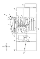
まず、本実施形態に係る画像形成装置Gの構成について説明する。
画像形成装置Gは、図1に示すように、プリントコントローラーg1、給紙ユニットg2、本体ユニットg3、画像読取装置g4及び後処理装置g5を備えている。
[Configuration of image forming apparatus]
First, the configuration of the image forming apparatus G according to the present embodiment will be described.
As shown in FIG. 1, the image forming apparatus G includes a print controller g1, a sheet feeding unit g2, a main body unit g3, an image reading device g4 and a post-processing device g5.
プリントコントローラーg1は、ネットワーク上のコンピューター端末からPDL(Page Description Language)データを受信し、当該PDLデータをラスタライズ処理してビットマップ形式の画像データを生成する。
プリントコントローラーg1は、C(シアン)、M(マジェンタ)、Y(イエロー)及びK(黒)の色ごとに画像データを生成し、本体ユニットg3に出力する。
The print controller g1 receives page description language (PDL) data from a computer terminal on a network, and rasterizes the PDL data to generate bitmap image data.
The print controller g1 generates image data for each color of C (cyan), M (magenta), Y (yellow) and K (black), and outputs the image data to the main unit g3.
給紙ユニットg2は、大容量の給紙トレイを複数備えている。
給紙ユニットg2は、本体ユニットg3により指示された給紙トレイから本体ユニットg3へ用紙を搬送する。
The sheet feeding unit g2 includes a plurality of large-capacity sheet feeding trays.
The sheet feeding unit g2 conveys a sheet from the sheet feeding tray instructed by the main body unit g3 to the main body unit g3.
本体ユニットg3は、スキャナー部6により原稿用紙Dを読み取って得られた画像データ又はプリントコントローラーg1により生成された画像データに基づき、画像形成部8により用紙上に画像を形成する。本体ユニットg3は、画像形成された用紙を画像読取装置g4へ搬送する。
The main body unit g3 forms an image on the sheet by the
画像読取装置g4は、読取部11において、用紙上に形成された基準画像(例えば、色、階調性補正、線幅、カラーレジスト、表裏位置合わせ用)を読み取り、読み取られた画像データを、制御部1に出力する。画像読取装置g4は、読取部11により画像の読み取りが行われた用紙を後処理装置g5へ搬送する。
The image reader g4 reads a reference image (for example, color, gradation correction, line width, color resist, front / back alignment) formed on a sheet by the
後処理装置g5は、画像読取装置g4から搬送された用紙を後処理して排紙する。後処理としては、例えばステイプル処理、パンチ穴開け処理、折り処理、製本処理等が挙げられる。後処理は必須ではなく、後処理装置g5は、本体ユニットg3から指示された場合のみ実行する。後処理が無い場合、後処理装置g5は搬送された用紙をそのまま排紙する。 The post-processing device g5 post-processes and discharges the sheet conveyed from the image reading device g4. Examples of the post-processing include staple processing, punching processing, folding processing, bookbinding processing, and the like. The post-processing is not essential, and the post-processing device g5 is executed only when instructed by the main unit g3. If there is no post-processing, the post-processing device g5 discharges the conveyed sheet as it is.
[本体ユニットの構成]
次に、本体ユニットg3の構成について説明する。
本体ユニットg3は、図1及び図2に示すように、制御部1と、記憶部2と、操作部3と、表示部4と、通信部5と、自動原稿搬送部61と、スキャナー部6と、画像処理装置7と、画像形成部8と、矯正部9と、給紙トレイg31と、を備えて構成されている。
[Configuration of main unit]
Next, the configuration of the main unit g3 will be described.
As shown in FIGS. 1 and 2, the
制御部1は、CPU、RAM等を備えている。制御部1は、記憶部2に記憶されているプログラムを読み出し、当該プログラムに従って画像形成装置Gの各部を制御する。
例えば、制御部1は、ジョブの設定に従い、給紙ユニットg2又は給紙トレイg31により用紙を給紙させる。また、制御部1は、画像処理装置7により画像データを補正及び画像処理させて、画像形成部8により画像を形成させる。また、制御部1は、ジョブの設定に後処理の設定が含まれる場合、後処理装置g5に指示して後処理を行わせる。
The control unit 1 includes a CPU, a RAM, and the like. The control unit 1 reads a program stored in the
For example, the control unit 1 causes the sheet feeding unit g2 or the sheet feeding tray g31 to feed a sheet according to the setting of the job. Further, the control unit 1 causes the
記憶部2は、制御部1が読み取り可能なプログラム、ファイル等を記憶している。記憶部2としては、例えばハードディスク、ROM等の記憶媒体を用いることができる。また、記憶部2は、画質調整用の基準画像のデータを記憶している。
The
操作部3は、操作キーや表示部4と一体に構成されたタッチパネル等を備え、これらの操作に応じた操作信号を制御部1に出力する。ユーザーは、操作部3により、ジョブの設定、処理内容の変更等の指示を入力することができる。
表示部4は、LCD(Liquid Crystal Display)等であることができ、制御部1の指示に従って操作画面等を表示する。
通信部5は、制御部1からの指示に従い、ネットワーク上のコンピューター、例えばサーバー又は他の画像形成装置と通信する。
The
The
The
自動原稿搬送部61は、原稿用紙Dを載置する載置トレイや原稿用紙Dを搬送する機構及び搬送ローラー等を備えて構成され、原稿用紙Dを所定の搬送経路に搬送する。
スキャナー部6は、光源や反射鏡等の光学系を備えて構成され、所定の搬送経路を搬送された原稿用紙D又はプラテンガラスに載置された原稿用紙Dの画像を読み取って、R(赤)、G(緑)及びB(青)の色ごとの画像データを生成し、画像処理装置7に出力する。
The automatic
The
画像処理装置7は、スキャナー部6又はプリントコントローラーg1から入力された画像データを補正し、画像処理を施して、画像形成部8に出力する。
画像処理装置7は、図2に示すように、色変換部71、階調補正部72及び中間調処理部73を備えている。
The
As shown in FIG. 2, the
色変換部71は、スキャナー部6から出力されたR、G及びBの各色の画像データを色変換処理し、C、M、Y及びKの各色の画像データを出力する。
色変換部71は、色補正のため、プリントコントローラーg1から出力されたC、M、Y及びKの各色の画像データを色変換処理し、色補正されたC、M、Y及びKの各色の画像データを出力することもできる。
色変換部71は、色変換処理時、R、G及びBの各色の階調値に対して、色変換後のC、M、Y及びKの各色の階調値が定められたLUTを用いる。色変換部71は、色補正時、C、M、Y及びKの各色の階調値に対して、色補正後のC、M、Y及びKの階調値が定められたLUTを用いる。
The
The
The
階調補正部72は、色変換部71又はプリントコントローラーg1から出力された画像データの階調を補正する。
階調補正部72は、階調の補正時、画像の階調特性が目標の階調特性に一致するように、各階調値に対応する補正値が定められたLUTを用いる。階調補正部72は、階調補正用のLUTから、画像データの各画素の階調値に対応する補正値を得て、補正値からなる画像データを出力する。
The
At the time of tone correction, the
中間調処理部73は、階調補正部72から出力された画像データを中間調処理する。中間調処理は、例えばディザマトリクスを用いたスクリーン処理、誤差拡散処理等である。
中間調処理部73は、中間調処理後の画像データを画像形成部8に出力する。
The
The
画像形成部8は、画像処理装置7から出力された画像データに基づき、用紙上に画像を形成する。
画像形成部8は、図1に示すように、C、M、Y及びKの色ごとに、露光部81、感光体82及び現像部83を、1セットずつ備えて構成されている。また、画像形成部8は、中間転写ベルト84、2次転写ローラー85、定着装置86を備えて構成されている。
The
As shown in FIG. 1, the
露光部81は、発光素子としてLD(Laser Diode)を備えている。露光部81は、画像データに基づいてLDを駆動し、帯電する感光体82上にレーザー光を照射して露光する。現像部83は、帯電する現像ローラーにより感光体82上にトナーを供給し、露光により感光体82上に形成された静電潜像を現像する。
このようにして4つの感光体82上に各色のトナーで形成された画像は、各感光体82から中間転写ベルト84上に順次重ねて転写される。これにより、中間転写ベルト84上にカラー画像が形成される。中間転写ベルト84は、複数のローラーに巻き回された無端ベルトであり、各ローラーの回転に従って回転する。
The
The images formed with the toners of the respective colors on the four
2次転写ローラー85は、中間転写ベルト84上のカラー画像を、給紙ユニットg2又は給紙トレイg31から給紙された用紙上に転写する。定着装置86は、転写後の用紙を加熱及び加圧して定着処理する。
The
矯正部9は、定着処理された用紙の変形を矯正し、用紙面を平面化する。ここで、用紙は定着処理によって変形しやすく、基準画像の読取時に用紙を平面化する必要がある。したがって、矯正部9は、図1に示すように、用紙の搬送方向において定着装置86と読取部11の間に配置されている。
The
[画像読取装置の構成]
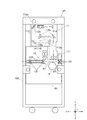
次に、画像読取装置g4の構成について説明する。
画像読取装置g4は、読取部11と、校正部12と、用紙搬送部13と、冷却部14と、を備えて構成されている。
[Configuration of image reader]
Next, the configuration of the image reading device g4 will be described.
The image reading device g4 includes a
読取部11は、用紙搬送部13により搬送経路R1を搬送される用紙上に形成された画像を所定の読取位置で読み取る。
読取部11は、図1及び図3に示すように、照明部111と、光学系112と、CCD(Charge Coupled Device)113と、を備えて構成されている。照明部111、光学系112及びCCD113は、いずれも読取部11の筐体内に固定されている。
The
As shown in FIGS. 1 and 3, the
照明部111は、LED(Light Emitting Diode)やハロゲンランプなどの光源を備え、搬送ローラー131により読取部11による読取位置に搬送された用紙を照明する。
光学系112は、複数(本実施形態では5つ)のミラー112aと、レンズ112bと、を備え、照明部111から用紙に照らされた光(読取位置の像)をCCD91に結像させる。
CCD113は、所定の読取位置で用紙上に形成された画像の読み取りを行う。CCD113は、用紙の幅方向(Y方向)における全幅の範囲を読み取り可能なカラーラインセンサーである。
The
The
The
読取部11は、上記の構成を備えることにより、読取位置を通過する用紙の全幅に亘って用紙上に形成された画像を順次読み取り可能となっている。例えば、本実施形態では、読取部11において、用紙上に形成された基準画像(例えば、色、階調性補正、線幅、カラーレジスト、表裏位置合わせ用)を読み取り、読み取られた画像データを本体エンジン、コントローラー、用紙搬送部等にフィードバックして、補正処理が行われる。
By having the above-described configuration, the
校正部12は、搬送経路R1の下方であって、読取部11と対向する位置に設けられている。校正部12は、画像の読み取りの際に行うシェーディング補正の補正値を決定するための白基準板を備えている。白基準板は、読取位置に設けられ、用紙の非通過時(例えば、用紙と用紙の合間等)に間隔を空けてCCD113による読み取りが行われる。
The
用紙搬送部13は、図2及び図4に示すように、搬送ローラー131と、駆動モーター132と、搬送ガイド133と、を備えて構成されている。
搬送ローラー(搬送部)131は、搬送経路R1上に複数設けられ、搬送経路R1に沿って用紙を搬送する。
駆動モーター(搬送駆動部)132は、制御部1の指示にしたがって、搬送ローラー131を駆動する。駆動モーター132は、搬送ローラー131よりも用紙の幅方向(Y方向)奥側に設けられている。
搬送ガイド133は、搬送経路R1上に複数設けられ、搬送ローラー131により搬送される用紙の搬送を案内する。
As shown in FIGS. 2 and 4, the
A plurality of conveyance rollers (conveyance units) 131 are provided on the conveyance path R1, and convey the sheet along the conveyance path R1.
The drive motor (conveyance drive unit) 132 drives the
A plurality of conveyance guides 133 are provided on the conveyance path R <b> 1 and guides conveyance of the sheet conveyed by the
用紙搬送部13は、読取部11で画像の読み取りが行われる際、搬送経路R1上に設けられた複数の搬送ローラー131により、用紙が所定の速度で読取部11による読取位置を通過するように、用紙搬送を行う。用紙搬送部13は、読取部11により画像の読み取りが行われた用紙を、後処理装置g5へと搬送する。
The
冷却部14は、図2及び図4に示すように、所定の方向に送風可能な送風ファン141と、送風ファン141を駆動する駆動モーター(送風駆動部)142と、を備えて構成されている。駆動モーター142は、送風ファン141よりも用紙の幅方向(Y方向)奥側に設けられている。
冷却部14は、送風ファン141が照明部111を向くように、搬送筐体101に固定されている。これにより、冷却部14は、照明部111に向けて送風することができるので、照明部111を冷却することができる。
As shown in FIGS. 2 and 4, the cooling
The cooling
搬送経路R1は、図4に示すように、複数の搬送ガイド133及び読取部11の底面等により、略直線状に構成される。搬送経路R1は、画像が形成された用紙を読取位置へと案内するとともに、読取部11により画像が読み取られた用紙を排出方向へと案内する。
As shown in FIG. 4, the transport route R <b> 1 is formed substantially linearly by the plurality of transport guides 133 and the bottom surface of the
画像読取装置g4の構成のうち、読取部11を除く、校正部12、用紙搬送部13(搬送ローラー131及び駆動モーター132)、冷却部14及び搬送経路R1は、搬送筐体101に固定され、保持されている。
また、読取部11及び搬送筐体101は、骨格102に個別に固定され、保持されている。
上記の構成を備えることで、用紙と搬送ガイド133や搬送ローラー131との衝突時に発生する振動が、搬送筐体101→骨格102→読取部11の順に伝搬するので、読取部11の伝わるまでの距離を十分確保することが可能となり、振動を十分に減衰させることができる。
Of the configuration of the image reading device g4, the
In addition, the
With the above configuration, the vibration generated at the time of collision between the sheet and the
[画像形成装置の用紙搬送制御]
次に、本実施形態に係る画像形成装置Gの用紙搬送制御について説明する。
本実施形態では、読取部11による読み取り中の用紙の搬送速度が750mm/sec以下であることが好ましい。これは、読取部11による読み取り中の用紙の搬送速度が速くなればなるほど、用紙と搬送ガイド133や搬送ローラー131との衝突時に発生する振動が強くなるからである。用紙の搬送速度を上記の範囲内とすることで、用紙と搬送ガイド133や搬送ローラー131との衝突時に発生する振動を抑制することができる。したがって、本実施形態では、制御部1が、読取部11による読み取り中の用紙の搬送速度が750mm/secとなるように駆動モーター132を制御することで、搬送ローラー131が、読取部11による読み取り中の用紙を750mm/sec以下の搬送速度で搬送するようにしている。
[Sheet conveyance control of image forming apparatus]
Next, sheet conveyance control of the image forming apparatus G according to the present embodiment will be described.
In the present embodiment, the conveyance speed of the sheet being read by the
また、本実施形態では、搬送される用紙の坪量が400g/m2以下であることが好ましい。これは、搬送される用紙の坪量が大きくなればなるほど、用紙と搬送ガイド133や搬送ローラー131との衝突時に発生する振動が強くなるからである。用紙の坪量を上記の範囲内とすることで、用紙と搬送ガイド133や搬送ローラー131との衝突時に発生する振動を抑制することができる。したがって、本実施形態では、搬送ローラー131が、坪量が400g/m2以下の用紙を搬送するようにしている。
Further, in the present embodiment, it is preferable that the basis weight of the transported sheet is 400 g / m 2 or less. This is because the larger the basis weight of the sheet to be conveyed, the stronger the vibration generated at the time of the collision between the sheet and the
[効果]
以上のように、本実施形態に係る画像形成装置Gの画像読取装置g4は、用紙上に形成された画像を所定の読取位置で読み取る読取部11と、画像が形成された用紙を読取位置へと案内するとともに、読取部11により画像が読み取られた用紙を排出方向へと案内する搬送経路R1と、搬送経路R1に沿って用紙を搬送する搬送部(搬送ローラー131)と、搬送部を駆動する搬送駆動部(駆動モーター132)と、搬送経路R1、搬送部及び搬送駆動部を保持する搬送筐体101と、読取部11内に固定され、搬送部により読取位置に搬送された用紙を照明する照明部111と、照明部111を冷却する冷却部14と、読取部11及び搬送筐体101を個別に固定する骨格102と、を備える。また、冷却部14は、搬送筐体101に固定されている。
したがって、本実施形態に係る画像読取装置g4によれば、照明部111を冷却することができるので、照明部111の照度を安定させることができる。また、用紙と搬送ガイド133や搬送ローラー131との衝突時に発生する振動が、搬送筐体101→骨格102→読取部11の順に伝搬するので、振動が読取部11に伝わるまでの距離を十分確保することが可能となり、振動を十分に減衰させることができる。よって、照明部111の照度を安定させつつ、用紙上に形成された画像を正確に読み取ることができる。
[effect]
As described above, the image reading device g4 of the image forming apparatus G according to this embodiment reads the image formed on the sheet at the predetermined reading position, and the sheet on which the image is formed to the reading position And guides the sheet on which the image is read by the
Therefore, according to the image reading device g4 according to the present embodiment, since the
また、本実施形態に係る画像読取装置g4によれば、読取部11は、一部が搬送経路R1を構成している。
したがって、本実施形態に係る画像読取装置g4によれば、読取部11と用紙との接触により読取部11に振動が伝わるケースであっても、他の振動源から伝わる振動を減衰させることで、用紙上に形成された画像を正確に読み取ることができる。
Further, according to the image reading device g4 according to the present embodiment, a part of the
Therefore, according to the image reading apparatus g4 according to the present embodiment, even in the case where the vibration is transmitted to the
また、本実施形態に係る画像読取装置g4によれば、冷却部14は、照明部111に向けて送風する送風ファン141と、送風ファン141を駆動する送風駆動部(駆動モーター142)と、を備える。
したがって、本実施形態に係る画像読取装置g4によれば、振動源となる駆動モーター142から読取部11に振動が伝わるまでの距離を十分確保することができるので、振動を十分に減衰させることが可能となり、用紙上に形成された画像を正確に読み取ることができる。
Further, according to the image reading device g4 according to the present embodiment, the cooling
Therefore, according to the image reading device g4 according to the present embodiment, a sufficient distance until the vibration is transmitted from the
また、本実施形態に係る画像読取装置g4によれば、搬送部は、読取部11による読み取り中の用紙を750mm/sec以下の搬送速度で搬送する。
したがって、本実施形態に係る画像読取装置g4によれば、用紙と搬送ガイド133や搬送ローラー131との衝突時に発生する振動を抑制することができるので、用紙上に形成された画像をより正確に読み取ることができる。
Further, according to the image reading device g4 according to the present embodiment, the conveyance unit conveys the sheet being read by the
Therefore, according to the image reading device g4 according to the present embodiment, it is possible to suppress the vibration generated at the time of the collision between the sheet and the
また、本実施形態に係る画像読取装置g4によれば、搬送部は、坪量が400g/m2以下の用紙を搬送する。
したがって、本実施形態に係る画像読取装置g4によれば、用紙と搬送ガイド133や搬送ローラー131との衝突時に発生する振動を抑制することができるので、用紙上に形成された画像をより正確に読み取ることができる。
Further, according to the image reading device g4 according to the present embodiment, the conveyance unit conveys a sheet having a basis weight of 400 g / m 2 or less.
Therefore, according to the image reading device g4 according to the present embodiment, it is possible to suppress the vibration generated at the time of the collision between the sheet and the
以上、本発明に係る実施形態に基づいて具体的に説明したが、本発明は上記実施形態に限定されるものではなく、その要旨を逸脱しない範囲で変更可能である。 As mentioned above, although it explained concretely based on the embodiment concerning the present invention, the present invention is not limited to the above-mentioned embodiment, and can be changed in the range which does not deviate from the gist.
[変形例]
例えば、上記実施形態では、略直線状の搬送経路R1を例示して説明しているが、これに限定されるものではない。すなわち、搬送経路R1内に、屈曲形成された屈曲部を含む構成であってもよい。もっとも、屈曲部は、屈曲角度が15°以下であることが好ましい。これは、屈曲部の屈曲角度が大きくなればなるほど、用紙と屈曲部近傍の搬送ガイド133や搬送ローラー131との衝突時に発生する振動が強くなるからである。特に、屈曲部の屈曲角度を15°以下とすることで、読み取り時における振動による影響を無視することができる程度に、用紙と屈曲部近傍の搬送ガイド133や搬送ローラー131との衝突時に発生する振動を十分抑制することができる。
[Modification]
For example, although the substantially linear transport route R1 is illustrated and described in the above embodiment, the present invention is not limited to this. That is, the configuration may include a bent portion formed to be bent in the transport route R1. However, the bending portion preferably has a bending angle of 15 ° or less. This is because the larger the bending angle of the bent portion, the stronger the vibration generated at the time of the collision between the sheet and the
上記のように、搬送経路R1に、屈曲形成された屈曲部が含まれている場合に、屈曲部の屈曲角度を15°以下とすることで、用紙と屈曲部近傍の搬送ガイド133や搬送ローラー131との衝突時に発生する振動を十分抑制することができるので、用紙上に形成された画像を正確に読み取ることができる。
As described above, when the bent portion formed by bending is included in the conveyance path R1, by setting the bending angle of the bent portion to 15 ° or less, the sheet and the
[その他の変形例]
また、上記実施形態では、冷却部14として、送風ファン141及び駆動モーター142を備える構成を例示して説明しているが、これに限定されるものではない。例えば、ポンプを用いて水を循環させることで、対象物を冷却する水冷装置を用いるようにしてもよい。この場合でも、水冷装置を搬送筐体101に固定することで、ポンプの振動を十分に減衰させることができる。
[Other modifications]
Moreover, in the said embodiment, although the structure provided with the
また、上記実施形態では、読取部11の筐体を、底面側の一部(図中右側)が下方に突出するL字形状に形成しているが、これに限定されるものではない。すなわち、読み取りに必要な光路長を確保できる形状であればいかなる形状であってもよく、例えば、読取部11の筐体を、底面側の一部が下方に突出しない箱状に形成するようにしてもよい。また、読取部11の筐体を、底面側の中央部が下方に突出する凸字形状に形成するようにしてもよい。ただし、読取部11の底面は、搬送経路R1を兼ねることから、用紙との接触による振動の発生を避けるべく、用紙との接触面積が狭い構成(例えば、L字形状や凸字形状の構成)の方がより好ましい。
In the above embodiment, the housing of the
また、上記実施形態では、冷却部14を、読取部11の突出部の搬送方向下流側に設けるようにしているが、これに限定されるものではない。すなわち、冷却部14を、読取部11の突出部の搬送方向上流側に設けるようにしてもよい。なお、読取部11の筐体を箱状に形成するケースでは、搬送方向上流側又は下流側のうち、光源から近い方に設けることが好ましい。
Further, in the above-described embodiment, the cooling
また、上記実施形態では、搬送経路R1を挟んで上方に読取部11を、下方に校正部12を、それぞれ配置する構成を採用しているが、これに限定されるものではない。例えば、搬送経路R1を挟んで上方に校正部12を、下方に読取部11を、それぞれ配置する構成を採用するようにしてもよい。
In the above-described embodiment, the
また、上記実施形態では、読取部11及び校正部12をそれぞれ1つずつ配置する構成を採用しているが、これに限定されるものではない。例えば、読取部11及び校正部12をそれぞれ2つずつ配置する構成を採用するようにしてもよい。この場合、一方は、搬送経路R1を挟んで上方に読取部11を下方に校正部12をそれぞれ配置する構成を採用し、他方は、搬送経路を挟んで上方に校正部12を下方に読取部11をそれぞれ配置する構成を採用することで、片面ずつ画像を読み取ることができるので、一度の用紙搬送で用紙両面の画像を読み取ることができる。
Further, in the above embodiment, although the configuration in which the
その他、画像形成装置を構成する各装置の細部構成及び各装置の細部動作に関しても、本発明の趣旨を逸脱することのない範囲で適宜変更可能である。 In addition, the detailed configurations of the respective devices constituting the image forming apparatus and the detailed operations of the respective devices can be appropriately modified without departing from the scope of the present invention.
G 画像形成装置
g1 プリントコントローラー
g2 給紙ユニット
g3 本体ユニット
1 制御部
2 記憶部
3 操作部
4 表示部
5 通信部
61 自動原稿搬送部
6 スキャナー部
7 画像処理装置
8 画像形成部
9 矯正部
g4 画像読取装置
11 読取部
12 校正部
13 用紙搬送部
131 搬送ローラー(搬送部)
132 駆動モーター(搬送駆動部)
133 搬送ガイド
14 冷却部
141 送風ファン
142 駆動モーター(送風駆動部)
101 搬送筐体
102 骨格
R1 搬送経路
g5 後処理装置
G image forming apparatus g1 print controller g2 sheet feeding unit g3 main unit 1
132 Drive motor (Transport drive unit)
133 Conveying
101
Claims (9)
前記画像が形成された用紙を前記読取位置を通過するように搬送する搬送部と、
前記読取部内に固定され、前記搬送部により前記読取位置に搬送された用紙を照明する照明部と、
振動源を有し、前記照明部を冷却する冷却部と、
筐体と、
前記読取部及び前記筐体を個別に保持する骨格と、
を備え、
前記冷却部は、前記筐体に保持されていることを特徴とする画像読取装置。 A reading unit that reads an image formed on a sheet at a predetermined reading position;
A conveyance unit configured to convey the sheet on which the image is formed so as to pass the reading position;
An illumination unit which is fixed in the reading unit and illuminates the sheet conveyed to the reading position by the conveyance unit;
A cooling unit having a vibration source and cooling the lighting unit;
A housing,
A frame that holds the reading unit and the case separately;
Equipped with
The image reading apparatus, wherein the cooling unit is held by the housing.
前記照明部に向けて送風する送風ファンと、
前記送風ファンを駆動し、前記振動源となる送風駆動部と、
を備えることを特徴とする請求項1〜3のいずれか一項に記載の画像読取装置。 The cooling unit is
A blower fan for blowing air toward the lighting unit;
A blower driving unit that drives the blower fan and serves as the vibration source ;
The image reading apparatus according to any one of claims 1 to 3, further comprising:
前記振動源となるポンプを用いて水を循環させることで前記照明部を冷却する水冷装置A water cooling apparatus for cooling the lighting unit by circulating water using a pump serving as the vibration source
を備えることを特徴とする請求項1〜3のいずれか一項に記載の画像読取装置。The image reading apparatus according to any one of claims 1 to 3, further comprising:
前記屈曲部は、屈曲角度が15°以下であることを特徴とする請求項1〜5のいずれか一項に記載の画像読取装置。 The conveyance path along which the conveyance unit conveys the sheet includes a bent portion formed by bending;
The image reading apparatus according to any one of claims 1 to 5 , wherein the bending portion has a bending angle of 15 ° or less.
前記画像形成部により用紙上に形成された画像を読み取る請求項1〜8のいずれか一項に記載の画像読取装置と、
を備えることを特徴とする画像形成装置。 An image forming unit that forms an image based on image data;
The image reading apparatus according to any one of claims 1 to 8 , wherein the image forming unit reads an image formed on a sheet.
An image forming apparatus comprising:
Priority Applications (3)
| Application Number | Priority Date | Filing Date | Title |
|---|---|---|---|
| JP2017062802A JP6531771B2 (en) | 2017-03-28 | 2017-03-28 | Image reading apparatus and image forming apparatus |
| US15/928,832 US10506126B2 (en) | 2017-03-28 | 2018-03-22 | Image reading apparatus and image forming system |
| CN201810249307.3A CN108668047A (en) | 2017-03-28 | 2018-03-26 | Image read-out and image forming apparatus |
Applications Claiming Priority (1)
| Application Number | Priority Date | Filing Date | Title |
|---|---|---|---|
| JP2017062802A JP6531771B2 (en) | 2017-03-28 | 2017-03-28 | Image reading apparatus and image forming apparatus |
Publications (3)
| Publication Number | Publication Date |
|---|---|
| JP2018166266A JP2018166266A (en) | 2018-10-25 |
| JP2018166266A5 JP2018166266A5 (en) | 2019-03-22 |
| JP6531771B2 true JP6531771B2 (en) | 2019-06-19 |
Family
ID=63670196
Family Applications (1)
| Application Number | Title | Priority Date | Filing Date |
|---|---|---|---|
| JP2017062802A Active JP6531771B2 (en) | 2017-03-28 | 2017-03-28 | Image reading apparatus and image forming apparatus |
Country Status (3)
| Country | Link |
|---|---|
| US (1) | US10506126B2 (en) |
| JP (1) | JP6531771B2 (en) |
| CN (1) | CN108668047A (en) |
Family Cites Families (17)
| Publication number | Priority date | Publication date | Assignee | Title |
|---|---|---|---|---|
| KR950003927A (en) * | 1993-07-27 | 1995-02-17 | 김광호 | Image Forming Device |
| JP2002287066A (en) * | 2001-03-27 | 2002-10-03 | Fuji Photo Film Co Ltd | Light beam cutoff device |
| US6909494B2 (en) * | 2003-02-10 | 2005-06-21 | Canon Kabushiki Kaisha | Image forming apparatus |
| US7051941B2 (en) * | 2003-03-03 | 2006-05-30 | Nisca Corporation | Image reading unit and image reading apparatus |
| JP4598591B2 (en) * | 2005-04-28 | 2010-12-15 | 京セラミタ株式会社 | Paper transport branch device |
| JP4699193B2 (en) * | 2005-09-14 | 2011-06-08 | 株式会社リコー | Image reading apparatus and image forming apparatus |
| JP5004028B2 (en) | 2008-04-25 | 2012-08-22 | ニスカ株式会社 | Image reading device |
| JP5652123B2 (en) * | 2010-10-22 | 2015-01-14 | 富士ゼロックス株式会社 | Detection device, image forming device |
| CN103621053B (en) * | 2011-06-20 | 2016-06-22 | 立志凯株式会社 | Image-reading device |
| JP5542779B2 (en) * | 2011-11-01 | 2014-07-09 | シャープ株式会社 | Image reading device |
| JP5553083B2 (en) * | 2012-04-09 | 2014-07-16 | コニカミノルタ株式会社 | Method for controlling sheet feeding device and image forming system |
| JP5750418B2 (en) * | 2012-09-20 | 2015-07-22 | 京セラドキュメントソリューションズ株式会社 | Sheet conveying apparatus and image forming apparatus provided with the same |
| JP6059508B2 (en) * | 2012-10-30 | 2017-01-11 | ニスカ株式会社 | Illumination apparatus and image reading apparatus using the illumination apparatus |
| JP6359898B2 (en) * | 2014-07-03 | 2018-07-18 | シャープ株式会社 | Illumination apparatus, image reading apparatus, and image forming apparatus including the same |
| US9407780B2 (en) * | 2014-12-11 | 2016-08-02 | Kyocera Document Solutions Inc. | Light scanning device and image forming apparatus including the same |
| US9798138B2 (en) * | 2015-01-30 | 2017-10-24 | Canon Kabushiki Kaisha | Optical scanning device, image forming apparatus, and imaging optical element |
| JP6332161B2 (en) * | 2015-06-22 | 2018-05-30 | コニカミノルタ株式会社 | Image reading apparatus and image forming system |
-
2017
- 2017-03-28 JP JP2017062802A patent/JP6531771B2/en active Active
-
2018
- 2018-03-22 US US15/928,832 patent/US10506126B2/en active Active
- 2018-03-26 CN CN201810249307.3A patent/CN108668047A/en active Pending
Also Published As
| Publication number | Publication date |
|---|---|
| US10506126B2 (en) | 2019-12-10 |
| JP2018166266A (en) | 2018-10-25 |
| CN108668047A (en) | 2018-10-16 |
| US20180288269A1 (en) | 2018-10-04 |
Similar Documents
| Publication | Publication Date | Title |
|---|---|---|
| JP6323191B2 (en) | Image reading apparatus and image forming apparatus | |
| JP5976618B2 (en) | Image forming apparatus | |
| US10200565B2 (en) | Image forming system and reading device | |
| JP2021044697A (en) | Image forming apparatus | |
| JP6350506B2 (en) | Image reading apparatus and image forming system | |
| US8155544B2 (en) | Image forming apparatus and image adjusting method involving a fluctuation-information acquiring unit and a control unit that forms a gradation pattern | |
| JP6540739B2 (en) | Image reading apparatus and image forming apparatus | |
| JP6531771B2 (en) | Image reading apparatus and image forming apparatus | |
| AU2011202939B2 (en) | Detecting device, detecting method, and image forming apparatus | |
| JP7140592B2 (en) | Measuring device, image forming device | |
| US10338511B2 (en) | Reading apparatus and image forming apparatus with guide member to guide sheet from first feeding path to second feeding path | |
| JP6544334B2 (en) | Image reading apparatus and image forming apparatus | |
| US20200296225A1 (en) | Image forming apparatus that uses spectral sensor | |
| JP7167199B2 (en) | Image reading device and image forming device | |
| JP5854820B2 (en) | Image forming apparatus | |
| US20180164726A1 (en) | Image forming apparatus | |
| JP6634889B2 (en) | Image forming device | |
| JP2018142845A (en) | Image reading device and image forming apparatus | |
| JP6344278B2 (en) | Image reading apparatus and image forming apparatus | |
| JP6860036B2 (en) | Image reader and image forming device | |
| US11201985B2 (en) | Information processing apparatus and image forming apparatus to align print positions | |
| US20110044712A1 (en) | Image forming apparatus | |
| JP2015211315A (en) | Image reader and image forming apparatus | |
| JP2011176614A (en) | Image reading apparatus, image processing apparatus, image adjustment method and image for adjustment | |
| JP2017183819A (en) | Optical device and image reader |
Legal Events
| Date | Code | Title | Description |
|---|---|---|---|
| A621 | Written request for application examination |
Free format text: JAPANESE INTERMEDIATE CODE: A621 Effective date: 20181214 |
|
| A521 | Written amendment |
Free format text: JAPANESE INTERMEDIATE CODE: A523 Effective date: 20190207 |
|
| A131 | Notification of reasons for refusal |
Free format text: JAPANESE INTERMEDIATE CODE: A131 Effective date: 20190305 |
|
| A521 | Written amendment |
Free format text: JAPANESE INTERMEDIATE CODE: A523 Effective date: 20190412 |
|
| TRDD | Decision of grant or rejection written | ||
| A01 | Written decision to grant a patent or to grant a registration (utility model) |
Free format text: JAPANESE INTERMEDIATE CODE: A01 Effective date: 20190423 |
|
| A61 | First payment of annual fees (during grant procedure) |
Free format text: JAPANESE INTERMEDIATE CODE: A61 Effective date: 20190506 |
|
| R150 | Certificate of patent or registration of utility model |
Ref document number: 6531771 Country of ref document: JP Free format text: JAPANESE INTERMEDIATE CODE: R150 |