JP5750418B2 - Sheet conveying apparatus and image forming apparatus provided with the same - Google Patents
Sheet conveying apparatus and image forming apparatus provided with the same Download PDFInfo
- Publication number
- JP5750418B2 JP5750418B2 JP2012206927A JP2012206927A JP5750418B2 JP 5750418 B2 JP5750418 B2 JP 5750418B2 JP 2012206927 A JP2012206927 A JP 2012206927A JP 2012206927 A JP2012206927 A JP 2012206927A JP 5750418 B2 JP5750418 B2 JP 5750418B2
- Authority
- JP
- Japan
- Prior art keywords
- sheet
- conveying
- guide
- conveyance
- roller pair
- Prior art date
- Legal status (The legal status is an assumption and is not a legal conclusion. Google has not performed a legal analysis and makes no representation as to the accuracy of the status listed.)
- Expired - Fee Related
Links
Images
Classifications
-
- B—PERFORMING OPERATIONS; TRANSPORTING
- B65—CONVEYING; PACKING; STORING; HANDLING THIN OR FILAMENTARY MATERIAL
- B65H—HANDLING THIN OR FILAMENTARY MATERIAL, e.g. SHEETS, WEBS, CABLES
- B65H5/00—Feeding articles separated from piles; Feeding articles to machines
- B65H5/06—Feeding articles separated from piles; Feeding articles to machines by rollers or balls, e.g. between rollers
- B65H5/068—Feeding articles separated from piles; Feeding articles to machines by rollers or balls, e.g. between rollers between one or more rollers or balls and stationary pressing, supporting or guiding elements
-
- B—PERFORMING OPERATIONS; TRANSPORTING
- B65—CONVEYING; PACKING; STORING; HANDLING THIN OR FILAMENTARY MATERIAL
- B65H—HANDLING THIN OR FILAMENTARY MATERIAL, e.g. SHEETS, WEBS, CABLES
- B65H5/00—Feeding articles separated from piles; Feeding articles to machines
- B65H5/06—Feeding articles separated from piles; Feeding articles to machines by rollers or balls, e.g. between rollers
- B65H5/062—Feeding articles separated from piles; Feeding articles to machines by rollers or balls, e.g. between rollers between rollers or balls
-
- B—PERFORMING OPERATIONS; TRANSPORTING
- B65—CONVEYING; PACKING; STORING; HANDLING THIN OR FILAMENTARY MATERIAL
- B65H—HANDLING THIN OR FILAMENTARY MATERIAL, e.g. SHEETS, WEBS, CABLES
- B65H5/00—Feeding articles separated from piles; Feeding articles to machines
- B65H5/36—Article guides or smoothers, e.g. movable in operation
- B65H5/38—Article guides or smoothers, e.g. movable in operation immovable in operation
-
- B—PERFORMING OPERATIONS; TRANSPORTING
- B65—CONVEYING; PACKING; STORING; HANDLING THIN OR FILAMENTARY MATERIAL
- B65H—HANDLING THIN OR FILAMENTARY MATERIAL, e.g. SHEETS, WEBS, CABLES
- B65H9/00—Registering, e.g. orientating, articles; Devices therefor
-
- B—PERFORMING OPERATIONS; TRANSPORTING
- B65—CONVEYING; PACKING; STORING; HANDLING THIN OR FILAMENTARY MATERIAL
- B65H—HANDLING THIN OR FILAMENTARY MATERIAL, e.g. SHEETS, WEBS, CABLES
- B65H9/00—Registering, e.g. orientating, articles; Devices therefor
- B65H9/004—Deskewing sheet by abutting against a stop, i.e. producing a buckling of the sheet
- B65H9/006—Deskewing sheet by abutting against a stop, i.e. producing a buckling of the sheet the stop being formed by forwarding means in stand-by
-
- B—PERFORMING OPERATIONS; TRANSPORTING
- B65—CONVEYING; PACKING; STORING; HANDLING THIN OR FILAMENTARY MATERIAL
- B65H—HANDLING THIN OR FILAMENTARY MATERIAL, e.g. SHEETS, WEBS, CABLES
- B65H2404/00—Parts for transporting or guiding the handled material
- B65H2404/50—Surface of the elements in contact with the forwarded or guided material
- B65H2404/51—Cross section, i.e. section perpendicular to the direction of displacement
- B65H2404/512—Cross section, i.e. section perpendicular to the direction of displacement concave
-
- B—PERFORMING OPERATIONS; TRANSPORTING
- B65—CONVEYING; PACKING; STORING; HANDLING THIN OR FILAMENTARY MATERIAL
- B65H—HANDLING THIN OR FILAMENTARY MATERIAL, e.g. SHEETS, WEBS, CABLES
- B65H2404/00—Parts for transporting or guiding the handled material
- B65H2404/60—Other elements in face contact with handled material
- B65H2404/61—Longitudinally-extending strips, tubes, plates, or wires
- B65H2404/611—Longitudinally-extending strips, tubes, plates, or wires arranged to form a channel
- B65H2404/6111—Longitudinally-extending strips, tubes, plates, or wires arranged to form a channel and shaped for curvilinear transport path
-
- B—PERFORMING OPERATIONS; TRANSPORTING
- B65—CONVEYING; PACKING; STORING; HANDLING THIN OR FILAMENTARY MATERIAL
- B65H—HANDLING THIN OR FILAMENTARY MATERIAL, e.g. SHEETS, WEBS, CABLES
- B65H2601/00—Problem to be solved or advantage achieved
- B65H2601/50—Diminishing, minimizing or reducing
- B65H2601/52—Diminishing, minimizing or reducing entities relating to handling machine
- B65H2601/521—Noise
Landscapes
- Engineering & Computer Science (AREA)
- Mechanical Engineering (AREA)
- Feeding Of Articles By Means Other Than Belts Or Rollers (AREA)
Description
本発明は、例えば湾曲した搬送路のような、非直線的な部分を含んで設定されたシート搬送路を備えたシート搬送装置、及びこれを備えた画像形成装置に関する。 The present invention relates to a sheet conveying apparatus including a sheet conveying path set to include a non-linear portion such as a curved conveying path, and an image forming apparatus including the sheet conveying apparatus.
プリンター、複写機、ファクシミリ等の画像形成装置においては、装置本体内に、画像形成処理が施されるシートを、給紙部から画像形成部及び定着部を経由して排紙部まで搬送するシート搬送路が備えられている。このシート搬送路は、装置本体内での機器レイアウト上の制限や装置小型化の要請から、U字状に湾曲した部分を含むことが多い。この場合、搬送中のシートの搬送方向先端が、当該湾曲したシート搬送路を画定するガイド面に一旦衝突し、その後、シートはガイド面に倣って搬送される。上記のシートの衝突に伴い、衝撃性音が発生する。このような衝撃性音はユーザーに不快感を与えるものであり、とりわけシート処理枚数が50枚/分を越えるような高速機では、短周期で衝撃性音の発生が繰り返されるため、不快感は一層増大する。 In image forming apparatuses such as printers, copiers, and facsimiles, a sheet that carries an image forming process from the paper feed unit to the paper discharge unit via the image forming unit and the fixing unit in the apparatus main body. A transport path is provided. This sheet conveyance path often includes a U-shaped curved portion because of restrictions on the device layout in the apparatus main body and requests for apparatus miniaturization. In this case, the leading end in the transport direction of the sheet being transported once collides with the guide surface that defines the curved sheet transport path, and then the sheet is transported along the guide surface. Along with the collision of the sheet, an impact sound is generated. Such impulsive sounds are uncomfortable for the user. Especially in high speed machines where the number of sheets processed exceeds 50 sheets / minute, the generation of impulsive sounds is repeated in a short period. Further increase.
従来、シート搬送に伴う騒音を緩和するための技術がいくつか提案されている。特許文献1には、シートの先端をガイドする搬送補助部材を、衝撃吸収部材を用いてガイド面に固定する手法が開示されている。特許文献2には、ガイド面のシート幅方向中央部に凸部を設け、この凸部に樹脂シートを貼り付ける構造が開示されている。特許文献3には、搬送ガイドの先端部分を樹脂シートで覆う構造が開示されている。
Conventionally, several techniques for reducing noise associated with sheet conveyance have been proposed. Patent Document 1 discloses a technique of fixing a conveyance auxiliary member that guides the leading edge of a sheet to a guide surface using an impact absorbing member.
しかしながら、上記特許文献1〜3に開示された対策では、シート先端がガイド面に衝突する際に発する衝撃性音の抑制には不十分である。また、衝撃吸収性を備える他の部材をシート搬送路に追加する必要があるため、部品点数が増加するという問題もある。 However, the countermeasures disclosed in Patent Documents 1 to 3 are insufficient for suppressing impact sound generated when the leading end of the sheet collides with the guide surface. Moreover, since it is necessary to add another member having shock absorption to the sheet conveyance path, there is a problem that the number of parts increases.
本発明の目的は、シートを搬送する際に発生する衝撃性音を可及的に抑制することができるシート搬送装置、及びこれを備えた画像形成装置を提供することにある。 SUMMARY OF THE INVENTION An object of the present invention is to provide a sheet conveying apparatus capable of suppressing impact sound generated when conveying a sheet as much as possible, and an image forming apparatus including the sheet conveying apparatus.
本発明の一局面に係るシート搬送装置は、シートを搬送するシート搬送装置であって、非直線的な部分を含んで設定されたシート搬送路と、前記シート搬送路に配置され、シートを搬送する搬送手段と、前記シート搬送路の前記非直線的な部分に配置され、シートをガイドするガイド平面を有するガイド板と、を備え、前記ガイド平面は、ガイドリブが存在しない平坦な面からなり、前記ガイド板は、前記ガイド平面における前記シート搬送路を搬送されるシートの搬送方向先端のエッジが衝突する領域に、前記衝突により発生する衝撃性音の高周波成分を抑制する薄肉部を備える。 A sheet conveying apparatus according to one aspect of the present invention is a sheet conveying apparatus that conveys a sheet, and is disposed in a sheet conveying path that includes a non-linear portion, and is disposed in the sheet conveying path, and conveys the sheet. And a guide plate that is disposed in the non-linear portion of the sheet conveyance path and has a guide plane that guides the sheet, and the guide plane includes a flat surface on which no guide rib exists, The guide plate includes a thin portion that suppresses a high-frequency component of impact sound generated by the collision in a region where an edge at a leading end in a conveyance direction of the sheet conveyed along the sheet conveyance path on the guide plane collides.
この構成によれば、シート搬送路を搬送されるシートの搬送方向先端は、リブ等を備えない平面からなるガイド平面であって、当該ガイド平面の薄肉部に衝突する。薄肉部にシートの先端が衝突した場合、通常の肉厚を備える部分に比べて衝撃性音の高周波成分が低減される。従って、前記衝撃性音がユーザーに与える不快感を緩和することができる。 According to this configuration, the leading end in the conveyance direction of the sheet conveyed on the sheet conveyance path is a guide plane composed of a plane not provided with a rib or the like, and collides with a thin portion of the guide plane. When the leading edge of the sheet collides with the thin wall portion, the high frequency component of the impact sound is reduced as compared with the portion having a normal wall thickness. Therefore, the unpleasant feeling given to the user by the impact sound can be reduced.
上記構成において、前記シート搬送路の前記非直線的な部分は、U字状に湾曲した搬送路であり、前記ガイド平面は、前記U字状に湾曲した搬送路の外側面を画定していることが望ましい。 In the above configuration, the non-linear portion of the sheet conveying path is a U-shaped curved conveying path, and the guide plane defines an outer surface of the U-shaped curved conveying path. It is desirable.
U字状に湾曲した搬送路の外側面には、シートの搬送方向先端が強く衝突する傾向がある。このような外側面に、前記薄肉部を備えたガイド平面を配置することにより、衝撃性音を効果的に抑制することができる。 There is a tendency that the front end of the sheet in the conveyance direction strongly collides with the outer surface of the conveyance path curved in a U-shape. By disposing a guide plane having the thin portion on such an outer surface, impact sound can be effectively suppressed.
この場合、前記搬送手段は、シートをニップして搬送する搬送ローラー対であって、前記シート搬送路の所定位置に配置された第1搬送ローラー対と、前記第1の搬送ローラー対の上流側に配設される第2の搬送ローラー対とを含み、前記U字状に湾曲した搬送路は、前記第1の搬送ローラー対と前記第2の搬送ローラー対との間に配設されていることが望ましい。 In this case, the conveying unit is a pair of conveying rollers that nip and convey the sheet, and is upstream of the first conveying roller pair disposed at a predetermined position of the sheet conveying path and the first conveying roller pair. The U-shaped curved conveyance path is disposed between the first conveyance roller pair and the second conveyance roller pair. It is desirable.
上記のようなシート搬送路では、第2の搬送ローラー対にニップされて搬送力を与えられたシートの先端が、ガイド平面に衝突し、しかる後、第1搬送ローラー対にニップされ、シート搬送路の下流側に搬送される。このような、シート搬送路における第2の搬送ローラー対と第1の搬送ローラー対との間のシート搬送において、上記構成によれば、衝撃性音を効果的に抑制することができる。 In the sheet conveyance path as described above, the leading edge of the sheet nipped by the second conveyance roller pair and applied with the conveyance force collides with the guide plane, and then is nipped by the first conveyance roller pair to convey the sheet. It is conveyed downstream of the path. In such sheet conveyance between the second conveyance roller pair and the first conveyance roller pair in the sheet conveyance path, according to the above configuration, impact sound can be effectively suppressed.
この構成において、前記U字状に湾曲した搬送路の内側面は、凸形状に湾曲された凸ガイド面を備えたガイド部材の前記凸ガイド面で画定され、前記U字状に湾曲した搬送路の外側面は、前記ガイド板のガイド平面で画定されていることが望ましい。 In this configuration, an inner surface of the U-shaped curved conveying path is defined by the convex guide surface of a guide member having a convex guide surface curved in a convex shape, and the U-shaped curved conveying path. The outer surface of the guide plate is preferably defined by a guide plane of the guide plate.
この構成によれば、シートの先端が第1搬送ローラー対にニップされた後は、当該シートは専ら前記凸ガイド面と摺接するようになり、前記ガイド板のガイド平面とは接触しなくなる。従って、薄肉部にはシートの先端部のみが専ら接触し、シートと薄肉部とが常時接触しなくなる。このため、シートとの摺接に起因する薄肉部の劣化を抑止することができる。 According to this configuration, after the leading edge of the sheet is nipped by the first conveying roller pair, the sheet comes into sliding contact with the convex guide surface exclusively and does not come into contact with the guide plane of the guide plate. Therefore, only the leading end of the sheet is in contact with the thin portion, and the sheet and the thin portion are not always in contact. For this reason, it is possible to suppress the deterioration of the thin portion due to the sliding contact with the sheet.
また、前記第1搬送ローラー対が、シートの搬送を一時的に中断する搬送ローラー対であって、シートが前記第1搬送ローラー対の上流に撓んだ状態で一時的に待機するものであり、前記ガイド板の前記薄肉部には、シートの撓み部も接触することが望ましい。 The first conveyance roller pair is a conveyance roller pair that temporarily interrupts conveyance of the sheet, and temporarily waits in a state where the sheet is bent upstream of the first conveyance roller pair. It is desirable that the thin portion of the guide plate also contacts the bent portion of the sheet.
上記のシート搬送路の構成では、シート搬送が一時的に中断されることによってシートに撓み部が形成され、その撓み部がガイド平面に衝突し、衝撃性音を発生することになる。しかし、当該撓み部が接触する部分が上記薄肉部であるので、その衝撃性音の高周波成分を低減でき、不快感を抑制することができる。 In the above-described configuration of the sheet conveyance path, the sheet conveyance is temporarily interrupted, so that a bent portion is formed on the sheet, and the bent portion collides with the guide plane to generate an impact sound. However, since the part which the said bending part contacts is the said thin part, the high frequency component of the impact sound can be reduced and a discomfort can be suppressed.
上記の構成において、前記ガイド板は、前記薄肉部の搬送方向下流側に厚肉部を備え、前記厚肉部の背面には前記シート搬送路に合流するシートをガイドする背面ガイドが形成されていることが望ましい。
本発明の他の局面に係る画像形成装置は、シートに画像を形成する画像形成部と、前記画像形成部を経由してシートを搬送する上記のシート搬送装置と、を備える。
In the above configuration, the guide plate includes a thick portion on the downstream side in the conveyance direction of the thin portion, and a back guide for guiding a sheet that joins the sheet conveyance path is formed on the back surface of the thick portion. It is desirable.
An image forming apparatus according to another aspect of the present invention includes an image forming unit that forms an image on a sheet, and the above-described sheet conveying device that conveys the sheet via the image forming unit.
本発明によれば、シートを搬送する際に発生する衝撃性音を可及的に抑制することが可能なシート搬送装置、及びこれを備えた画像形成装置を提供することができる。 According to the present invention, it is possible to provide a sheet conveying apparatus capable of suppressing impact sound generated when conveying a sheet as much as possible, and an image forming apparatus including the sheet conveying apparatus.
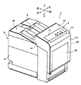
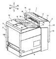
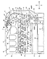
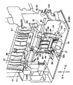
以下、図面に基づいて、本発明の実施形態を詳述する。まず、図1〜図3を参照して、本発明の一実施態様に係るシート搬送装置100を備えた画像形成装置1について説明する。なお、図1〜図3においては、画像形成装置1における上下前後左右の方向を矢印で示している。図1は、画像形成装置1の全体を、その前側の左斜め上方から見た斜視図、図2は、画像形成装置1の全体を、その左側の後斜め上方から見た斜視図、図3は、左側から見た画像形成装置1の内部の構造を模式的に示す図である。
Hereinafter, embodiments of the present invention will be described in detail with reference to the drawings. First, an image forming apparatus 1 including a
ここで、画像形成装置1としては、プリンター、複写機、ファクシミリ、及びこれらの複合機等が例示できるが、以下の説明では、画像形成装置1がプリンターである場合を例に説明する。同図に示す画像形成装置1は、電子写真方式、中間転写方式、タンデム方式を採用した、4色フルカラーの画像形成装置である。 Here, examples of the image forming apparatus 1 include a printer, a copying machine, a facsimile machine, and a multifunction machine of these. However, in the following description, the case where the image forming apparatus 1 is a printer will be described as an example. An image forming apparatus 1 shown in FIG. 1 is a four-color full-color image forming apparatus that employs an electrophotographic system, an intermediate transfer system, and a tandem system.
画像形成装置1は、ほぼ箱型(直方体状)の外形形状を備えた装置本体2と、この装置本体2によって開閉自在に支持された前面カバー3とを備えている。装置本体2は、前面が、前面カバー3によって覆われ、左側面及び右側面が左外装パネル4及び右外装パネル5によって覆われている。装置本体2の後面は、板金製の本体フレーム6の一部である後面板7が露出されている。装置本体2の上面は、前部が前面カバー3によって覆われ、中間部から後部にかけては、後上がりのシート積載面8を有する排紙トレイ10によって覆われている。
The image forming apparatus 1 includes an apparatus
前面カバー3は、前外装パネル11と、この内側に組み込まれた後述のシート搬送部24(図3参照)の一部とによって構成されている。前外装パネル11は、前パネル12と、この上端に続く後上がりの上パネル13と、逆「L」字形の左パネル14及び右パネル15とを含み、これらが一体化された構成を有する。
The front cover 3 is configured by a front
前パネル12には、矩形形状を有する手差しトレイ16が配設されている。手差しトレイ16は、その下端側において装置本体2に回動可能に取り付けられており、装置本体2に対して閉止姿勢と、開放姿勢とを取ることができる。図1は、手差しトレイ16が閉止姿勢の状態を示しており、この場合、手差しトレイ16は前パネル12の一部を構成する。一方、その上端側が前方に引き出された開放姿勢(図6参照)にあっては、手差しトレイ16の上面にシートが載置され、給紙台として利用される。
A
上パネル13には、操作情報の入力を受け付けるための操作パネル17が配置されている。操作パネル17は、画像形成装置1の正面側に立って操作するユーザーが見やすいように、後端側が少し高くなるように緩く傾斜してほぼ上向きに配置されている。操作パネル17には、タッチパネル式の液晶表示部や、各種ボタンが配置されている。ユーザーは、画像形成装置1の正面に立った状態で、この操作パネル17により画像形成装置1に対する各種の操作情報をすることが可能である。左パネル14及び右パネル15は、前面カバー3の内側に構成されたシート搬送部24の一部をそれぞれ左側及び右側から覆うように配設されている。
On the
前面カバー3は、その下端側において装置本体2に揺動自在に支持され、装置本体2に対して開閉自在である。前面カバー3が開放されるとき、前面カバー3の上端側が装置本体2から離間するように開く。左パネル14の上端側でかつ後端側、及び、右パネル15の上端側でかつ後端側には、前面カバー3が開放される際に操作される解除レバー74が配設されている。解除レバー74は、前面カバー3と装置本体2とを係合する図略のロック部材によるロック状態を解除するための部材である。ユーザーは、解除レバー74の上端に配置されたボタン75を手前側に押すことで、前記ロック状態を解除し、前面カバー3を開放することができる。
The front cover 3 is swingably supported by the apparatus
ユーザーは、画像形成装置1の正面側から前面カバー3を手前側に開いて開放することで、シートのジャム処理を行うことが可能である。また、画像形成対象となるシートが収納される給紙カセット25(図3参照)は、同じく正面側から着脱可能である。このように、ユーザーは、操作パネル17を使用しての画像形成装置1の操作全般、ジャムが発生したときのそのジャム処理、及び、給紙カセット25に対するシートの補給等を、すべて画像形成装置1の正面側から行うことができる。
The user can perform jam processing on the sheet by opening the front cover 3 from the front side of the image forming apparatus 1 to the front side and opening it. Further, a paper feed cassette 25 (see FIG. 3) in which a sheet to be image-formed is stored can be detached from the front side. In this way, the user performs all operations of the image forming apparatus 1 using the
次に、図3を参照して、画像形成装置1の内部の構造について説明する。画像形成装置1には、装置本体2の下側から上側かけて順に、シート収納部20、基板収納部21、画像形成部22、トナー補給部23、排紙トレイ10が設けられている。また、装置本体2の前側と、前面カバー3との間には、シート搬送部24が設けられている。
Next, the internal structure of the image forming apparatus 1 will be described with reference to FIG. In the image forming apparatus 1, a
シート収納部20には、給紙カセット25が配設されている。給紙カセット25は、複数枚のシートを積層状態で収納するものであり、この積層状態のシートの先端側(同図中の右側)を上方に付勢するリフト板26を底部に有する。給紙カセット25内の最上位のシートが、ピックアップローラー27によって繰り出される。ピックアップローラー27の下流側には給紙ローラー28及びリタードローラー30からなるローラー対が配置されている。給紙ローラー28及びリタードローラー30は、シートの重送を防止する機能を有し、1枚のシートだけを下流側に給送する。
A
基板収納部21には、画像形成装置1の動作を制御する電子部品が搭載された基板、画像形成装置1の各所に電力を供給するための電力機器、及び、その他の電装品等(不図示)が配設されている。 The substrate storage unit 21 includes a substrate on which electronic components for controlling the operation of the image forming apparatus 1 are mounted, power equipment for supplying power to various parts of the image forming apparatus 1, and other electrical components (not shown). ) Is arranged.
画像形成部22は、シートにトナー画像を形成する処理を行うもので、中間転写ベルト31と、この中間転写ベルト31の回転方向(矢印R31方向)に沿って配置された4つ(4色)の画像形成ステーションとを含む。4つの画像形成ステーションは、イエロー(Y)の画像形成ステーション32、マゼンタ(M)の画像形成ステーション33、シアン(C)の画像形成ステーション34、及び、ブラック(Bk)の画像形成ステーション35からなる。
The image forming unit 22 performs processing to form a toner image on a sheet. The
イエローの画像形成ステーション32は、感光ドラム36と、感光ドラム36の周囲にその回転方向(矢印方向)に沿って配設された、帯電装置37、露光装置38、現像装置40、1次転写ローラー41、ドラムクリーナ42とを含む。感光ドラム36は、その周面に静電潜像及びトナー像を担持するもので、図中の矢印方向に所定のプロセススピードで回転駆動される。帯電装置37は、感光ドラム36の周面を所定の極性及び電位で一様に帯電させる。露光装置38は、パーソナルコンピューター(不図示)等から送信される画像情報に基づくレーザー光を感光ドラム36の周面に照射し、該周面に静電潜像を形成される。現像装置40は、感光ドラム36の周面にトナーを供給し、前記静電潜像を現像して前記周面にトナー像を形成する。
The yellow
中間転写ベルト31は、駆動ローラー43と従動ローラー44とに張架されており、駆動ローラー43の矢印方向の回転によって矢印R31方向に回転する。この中間転写ベルト31を挟んで、感光ドラム36と1次転写ローラー41とによって1次転写部T1が形成されている。感光ドラム36の周面に形成されたイエローのトナー像は、1次転写部T1において中間転写ベルト31上に1次転写される。ドラムクリーナ42は、トナー像の1次転写後に感光ドラム36の周面に残存したトナーを除去する。
The
残りの3色(シアン,マゼンタ,ブラック)の画像形成ステーション33、34、35も、上述のイエローの画像形成ステーション32と同様の構成を備える。これらの画像形成ステーション33、34、35の感光ドラム36の表面にも同様にして、シアン、マゼンタ、ブラックの各色のトナー像が形成され、中間転写ベルト31上の同位置に順次1次転写される。こうして、4色のトナー像は、中間転写ベルト31上で重ね合わされ、フルカラーのトナー像が中間転写ベルト31上に形成される。
The remaining three color (cyan, magenta, and black)
駆動ローラー43に対向して、2次転写ローラー45が配置されている。駆動ローラー43と2次転写ローラー45とは、中間転写ベルト31を挟んで2次転写部T2を形成している。中間転写ベルト31に担持されたフルカラートナー像は、シート搬送部24によって搬送されるシートに、2次転写部T2において2次転写される。トナー像の2次転写後に中間転写ベルト31の表面に残ったトナーは、従動ローラー44の近傍に配置されたベルトクリーナ46によって除去される。
A
トナー補給部23には、各色のトナーをそれぞれ個別に収納した4つのトナーコンテナ、すなわちイエロー、マゼンタ、シアン、ブラックのトナーコンテナ47、48、50、51が配設されている。各色の現像装置40には、トナーの濃度(トナー/現像剤の重量比)を検知するための濃度センサ(不図示)が配設されている。この濃度センサが、現像装置40内のトナー量が所定値よりも少なくなったことを検知したときに、各色のトナーコンテナ47、48、50、51から各色の現像装置40にトナーが補給される。
The
排紙トレイ10は、装置本体2の上面を覆うように形成されている。排紙トレイ10の前後方向の中間部は、後端側が上方に位置するように傾斜しており、後端側はこの中間部に連続するように平らに形成されている。この排紙トレイ10の上面のシート積載面8には、次に説明するシート搬送部24のシート排出口55から後方に向かって排出されたシートが積載される。
The
シート搬送部24は、本実施形態においては、装置本体2の前側と前面カバー3との間に設けられている。シート搬送部24は、下方から上方に向かうシートをガイドするシート搬送路52と、このシート搬送路52よりも前側に配設されて、上方から下方に向かうシートをガイドする反転搬送路53と、手差し給送部54とを有している。反転搬送路53は、上述の前面カバー3の開放によって直接開放されるシート搬送路である。また、シート搬送路52は、前面カバー3の開放により、後述の搬送ユニット73を介して間接的に開放されるシート搬送路である。
In the present embodiment, the
シート搬送路52は、給紙ローラー28の近傍から上方に立ち上がり、後方に凸状にゆるく湾曲しながら上方に延び、中間転写ベルト31の近傍で、湾曲方向を前方に向かえて上方に延び、後方に向けて斜め上方に延びて、シート排出口55に至る。シート搬送路52は、相互に対面する後側ガイド52aと前側ガイド52bとによって構成されており、前側ガイド52bの一部が後述する搬送ユニット73に形成されている。
The
シート搬送路52には、下方から順に、ピックアップローラー27、給紙ローラー28及びリタードローラー30のローラー対、搬送ローラー対56、レジストローラー対57、上述の2次転写部T2を形成する駆動ローラー43及び2次転写ローラー45、定着ローラー対58、搬送ローラー対60、切り換えフラッパ61、排紙ローラー対62が配設されている。定着ローラー対58は、ヒータ(不図示)を内蔵した定着ローラー63と、定着ローラー63に当接されて間に定着ニップ部を構成する加圧ローラー64とを有している。
In the
給紙カセット25から1枚だけ給送されたシートは、搬送ローラー対56、レジストローラー対57によって2次転写部T2まで搬送される。続いてシートには、2次転写部T2において、中間転写ベルト31上の4色のトナー像が一括で2次転写され、前記定着ニップ部へ送られる。シートは、前記定着ニップ部を通過する際に加熱・加圧され、該シートにトナー像が定着される。
A single sheet fed from the
トナー像定着後のシートは、搬送ローラー対60によって切り換えフラッパ61の下面にガイドされて排紙ローラー対62に搬送される。さらに該シートは、排紙ローラー対62によって、背面側を向いたシート排出口55から後方に向けて排出され、排紙トレイ10のシート積載面8上に積載される。なお、図3では、排紙ローラー対62のすぐ下流側に配置された排紙センサのセンサフラグ65が、排出中のシートPによって動作している状態を示している。
The sheet after the toner image is fixed is guided to the lower surface of the switching
反転搬送路53は、シート排出口55の少し上から前側に向かって傾斜して延び、緩やかに湾曲しながら、急勾配で後側に傾斜して延び、下端部において下方に凸状に湾曲しながら、上述のシート搬送路52に合流する。反転搬送路53は、相互に対面する後側ガイド53aと前側ガイド53bとによって構成されている。後側ガイド53aの一部は、搬送ユニット73に形成されている。また、前側ガイド53bは、そのほとんどが外装パネル11の内側(後端側)に組み込まれている。反転搬送路53には、シートの反転搬送時に上流側となる上方から順に、反転ローラー対66、切り換えフラッパ61、第1,第2,第3,第4の反転搬送ローラー対67,68,70,71が配設されている。
The
シートの両面に画像が形成される場合には、切り換えフラッパ61が二点鎖線で示す位置に切り換えられる。表面にトナー像が定着されたシートは、搬送ローラー対60に搬送されて、切り換えフラッパ61の上面に沿って搬送され、さらに反転ローラー対66によって後方に向けて搬送される。そして、シートの後端が搬送ローラー対60を抜けて、反転ローラー対66を抜ける前に反転ローラー対66が逆回転され、シートは第1〜第4の反転搬送ローラー対67,68,70,71によって下方に搬送され、シート搬送路52に搬送される。そして、シートの裏面に、表面のときと同じようにしてトナー像が転写され、定着される。その後、当該シートはシート排出口55から後方に向けて排出されて、排紙トレイ10のシート積載面8に積載される。
When images are formed on both sides of the sheet, the switching
なお、シート搬送部24における搬送ローラー対56のすぐ前側には、手差し給紙ローラー72が配設されている。手差しトレイ16上にセットされたシートは、手差し給紙ローラー72によって、搬送ローラー対56側に向けて給紙される。
A manual
シート搬送部24は、その一部が開閉可能な搬送ユニット73によって構成されている。搬送ユニット73は、シート搬送路52と反転搬送路53との間に配置され、シート搬送路52における前側ガイド52bの一部と、反転搬送路53における後側ガイド53aの一部とを備える。また、搬送ユニット73には、レジストローラー対57の一方のローラー57a、2次転写ローラー45、第3,第4の反転搬送ローラー対70,71のそれぞれの一方のローラー70a,71aを支持している。この搬送ユニット73は、その下端側に揺動中心を有し、装置本体2によって開閉自在に支持されている。搬送ユニット73は、前面カバー3が開放されることにより、上端側が前側に開放されて、シート搬送路52の一部及び反転搬送路53の一部を開放する。
The
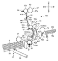
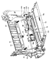
次に、図4〜図8を参照して、本発明の一実施形態に係るシート搬送装置100について説明する。本実施形態では、シート搬送装置100は、給紙カセット25からレジストローラー対57に至るまでのシート搬送路52に適用されている。図4は、シート搬送装置100を模式的に示す図、図5は、シート搬送路52を開放して、給紙ローラー28からレジストローラー対57に至るシート搬送路を示す斜視図、図6は、手差し給紙ローラー72からレジストローラー対57に至るシート搬送路を示す斜視図である。
Next, a
図4を参照して、シート搬送装置100は、レジストローラー対57(第1の搬送ローラー対)と、シートをニップして搬送する搬送ローラー対であって、シート搬送路52の所定位置(レジストローラー対57と給紙ローラー28との間の中間付近の位置)に配置された搬送ローラー対56(搬送手段;第1の搬送ローラー対又は第2の搬送ローラー対)と、搬送ローラー対56の上流側に配設された給紙ローラー28とリタードローラー30とからなるローラー対(搬送手段;第2の搬送ローラー対/以下適宜「給紙ローラー対101」という)及び手差し給紙ローラー72とを備えている。
Referring to FIG. 4, the
上述の通り、シート搬送路52は非直線的な搬送路である。具体的には、給紙ローラー対101と搬送ローラー対56との間において、シート搬送路52は前方に向けて凸となるようにU字状に湾曲しつつ上方に延びている。また、搬送ローラー対56とレジストローラー対57との間においては、逆に後方に向けて凸となるようにU字状に湾曲しつつ上方に延びている。給紙ローラー対101と搬送ローラー対56との間には、シート搬送路52を画定するために、リブ付きガイド板82及び第1ガイド板85(ガイド板)が配置されている。搬送ローラー対56とレジストローラー対57との間には、同じくシート搬送路52を画定するために、第2ガイド板88(ガイド板)が配置されている。
As described above, the
シートPは、給紙カセット25内の底板29上に積層状態で複数枚載置されている。底板29がリフト板26によって上方に付勢されることによって、シートの束の最上位のシートPがピックアップローラー27に当接している。ピックアップローラー27の矢印R27方向の回転によって、シートPは、給紙ローラー28とリタードローラー30との間の分離ニップ部N1に向けて給紙される。
A plurality of sheets P are placed in a stacked state on the
リタードローラー30は、トルクリミッタ80が装着されるとともに、分離ばね(圧縮ばね)81によって付勢され、その周面が給紙ローラー28の表面に当接されて分離ニップ部N1を形成している。リタードローラー30は、トルクリミッタ80の作用により、ピックアップローラー27から分離ニップ部N1に供給されたシートPが1枚だけの場合には、給紙ローラー28の矢印R28方向の回転によって分離ニップ部N1を搬送されるシートPに連れ回りして矢印R30方向に回転する。一方、分離ニップ部N1にシートPが2枚以上同時に供給されてしまった場合には、リタードローラー30は回転を停止して、2枚目以降のシートPを停止させて分離ニップ部N1を通過させない。
The
リブ付きガイド板82は、給紙ローラー対101と搬送ローラー対56との間における、U字状に湾曲したシート搬送路52の内側の側壁を構成している。リブ付きガイド板82は、図3に示すシート搬送路52の後側ガイド52aの一部を構成しており、前方側に向かって凸状に湾曲されたガイド面83(凸ガイド面)を有する。このガイド面83からはガイドリブ84が突設されている。ガイドリブ84は、ガイド板82と同様に、前方側に向かって凸状に湾曲した状態でシート搬送方向に沿って配設されている。また、ガイドリブ84は、シートPの通紙幅方向に複数配設されている(図5参照)。
The rib-equipped
第1ガイド板85は、リブ付きガイド板82に対向して配置され、U字状搬送路の外側の側壁を構成している。第1ガイド板85は、シートをガイドする第1ガイド平面85G(ガイド平面)を備える。第1ガイド平面85Gは、ガイド面83の凸面形状に対応して凹状に湾曲した面であり、当該第1ガイド平面85Gにはガイドリブの類は立設されていない。第1ガイド板85は、シートPの搬送方向先端が衝突する領域に、該衝突により発生する衝突音の高周波成分を抑制する薄肉部86を備えている。この第1ガイド板85については、図7に基づき後記で詳述する。
The
搬送ローラー対56は、ガイド板82、85のペアで形成される搬送路の直ぐ下流側に配置され、矢印R56方向に回転駆動される駆動ローラー56aと、圧縮ばね87によってこの駆動ローラー56aに当接されて従動回転する従動ローラー56bとを含む。駆動ローラー56aの周面と従動ローラー56bの周面とが互いに圧接されることによって、シートPをニップして搬送する搬送ニップ部N2が形成されている。
The
第2ガイド板88は、搬送ローラー対56とその下流側のレジストローラー対57との間における、U字状に湾曲したシート搬送路52の外側の側壁を構成している。第2ガイド板88は、図3に示すシート搬送路52の後側ガイド52aの一部を構成しており、後方側に向かって緩やかな凹状に湾曲された第2ガイド平面88G(ガイド平面)を有する。第2ガイド板88には、搬送されてきたシートPがレジストローラー対57に到達したことを検知する検知センサ91が配設されている。この第2ガイド板88については、図8に基づき後記で詳述する。
The
レジストローラー対57は、駆動ローラー57aと、圧縮ばね92に付勢されて駆動ローラー57aに当接される従動ローラー57bとによって構成されている。駆動ローラー57aと従動ローラー57bとの間には、搬送ニップ部N3が形成されている。レジストローラー対57は、シートPの搬送を一時的に中断してスキュー矯正を行い、2次転写部T2における転写タイミングに合わせてシートPの搬送を再開する。
The
図4及び図6を参照して、手差し給紙ローラー72は、手差しトレイ16からの手差しシートPMの搬送のために配置されたローラーである。手差し給紙ローラー72に対向して、摩擦板721が配置されている。摩擦板721は付勢バネ722によって手差し給紙ローラー72に向けて付勢されており、手差し給紙ローラー72と共に手差しシートPMのピックアップのためのニップ部を形成している。手差し給紙ローラー72の上流側には、手差しトレイ16に積載された手差しシートPMの先端部分を持ち上げる付勢板16aが配置されている。付勢板16aは、付勢バネ161によって上方に付勢されている。
With reference to FIGS. 4 and 6, the manual
上記のシート搬送装置100の構成において、ピックアップローラー27によって給紙カセット25から給紙されたシートPは、給紙ローラー対101によって1枚だけ分離されて、シート搬送路52に送り込まれる。引き続きシートPは、リブ付きガイド板82及び第1ガイド板85にガイドされて、搬送ローラー対56に到達する。なお、手差し給紙ローラー72によって送り出される手差しシートPMは、第1ガイド板85の上方を経由して搬送ローラー対56に向かう。
In the configuration of the
そして、シートP(手差しシートPM)は、搬送ローラー対56により搬送されつつ第2ガイド板88にガイドされて、停止中の(シートの搬送を一時的に中断している)レジストローラー対57のニップ部N3に先端が突き当てられる。シートPは、これにより斜行が矯正される。なお、搬送ローラー対56によって搬送力が与えられているシートPは、レジストローラー対57の上流側において撓んだ状態で待機することになる。
Then, the sheet P (manually fed sheet PM) is guided by the
シートPはその後、図3に示す中間転写ベルト31上に形成されたトナー像が、中間転写ベルト31の矢印R31方向の回転に伴って2次転写部T2に到達するタイミングに合わせて、レジストローラー対57により、2次転写部T2に向けて搬送される。この際、シートPは、レジストローラー対57の下流に配置されたガイド板96(図5及び図6参照)によってガイドされる。2次転写部T2に搬送されたシートPは、上述のように、トナー像が2次転写され、さらに定着された後、排紙トレイ10に排出される。
Thereafter, the sheet P is aligned with the timing at which the toner image formed on the
以上説明したシート搬送装置100において、U字状に湾曲したシート搬送路52の外側面を画定することになる第1ガイド板85の第1ガイド平面85G、及び、第2ガイド板88の第2ガイド平面88Gには、シートPの搬送方向先端が衝突することになる。また、第2ガイド平面88Gには、レジストローラー対57におけるスキュー矯正の際にシートPの撓み部が成長する過程において当該撓み部が衝突することになる。つまり、シートPが第1、第2ガイド平面85G、88Gを通過する際に衝撃性音が発生する。このような衝撃性音はユーザーに不快感を与える。特に、シート処理枚数が50枚/分を越えるような高速機では短周期で衝撃性音が繰り返されるため、不快感は一層増大する。そこで、本実施形態においては、第1ガイド板85及び第2ガイド板88に、上記衝撃性音を緩和するための工夫が施されている。以下、この点につき説明する。
In the
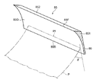
図7は、第1ガイド板85の斜視図である。第1ガイド板85は、左右方向に長い板状の部材からなり、シート搬送路52を通紙される最大サイズのシートPの幅よりも広幅の幅サイズを有する。第1ガイド板85の形成材料としては、樹脂が好適であり、例えばABS(Acrylonitrile butadiene styrene copolymer)樹脂を用いることができる。第1ガイド平面85Gは、第1ガイド板85の上流端縁85Bから下流端縁85Fにかけて、緩やかに凹状に湾曲した湾曲平面である。第1ガイド板85の肉厚は、上流端縁85Bの側が薄肉部86とされ、下流端縁85Fの側が厚肉部851とされている。つまり、第1ガイド板85の概ねシート搬送方向上流側半分が薄肉部86であり、中央部から下流端にかけて、凹曲面に沿って徐々に肉厚が厚くなる厚肉部851である。
FIG. 7 is a perspective view of the
薄肉部86は、シート搬送路52を搬送されるシートPの搬送方向先端Pfが衝突する領域に配置されている。図4も参照して、給紙ローラー対101によってシート搬送路52に送り込まれたシートPは、当該シート搬送路52が前側に凸の形状で上方に延びるU字状搬送路であるため、その搬送方向先端Pfが前記U字状搬送路の外側の側壁を構成する第1ガイド平面85Gに衝突する。先端Pfが第1ガイド平面85Gに衝突する際の入射角θは、シート搬送路52のU字湾曲の程度が大きい程、垂直に近くなる。
The
シートPの先端Pfは、薄肉部86に衝突した後、第1ガイド平面85Gの厚肉部851によってガイドされ、搬送ローラー対56の搬送ニップ部N2へ導かれる。搬送ニップ部N2によってニップされた後、シートPは、その搬送方向下流側が前記搬送ニップ部N2で、搬送方向上流側が給紙ローラー対101の分離ニップ部N1でニップされた状態となる。このとき、シートPは第1ガイド平面85Gに接触せず、前記U字状搬送路の内側の側壁を構成するリブ付きガイド板82のガイドリブ84に摺接する。なお、厚肉部851の背面には、背面ガイド852が形成されている。背面ガイド852は、手差しトレイ16の手差しシートPMが搬送ローラー対56に搬入される際に、当該手差しシートPMをガイドする。
After the front end Pf of the sheet P collides with the
ここで、シートPが、給紙ローラー対101と搬送ローラー対56との間を搬送される際、シートPの一方の面が、凸状に湾曲したガイドリブ84に摺擦されて、搬送擦れ音が発生する。本実施形態では、この搬送擦れ音を低減する工夫も施されている。搬送ローラー対56は、駆動ローラー56aと従動ローラー56bとからなるが、本実施形態では、図5に示すように、シート通紙幅方向に所定間隔をおいて配置される2つのローラーペアを有している。2個の駆動ローラー56aは、ローラー軸95に一体に固定されており、ローラー軸95の軸回りの回転で駆動ローラー56aが回転するローラー体を構成している。ローラー軸95は、その軸方向の左端部95aと右端部95bとが、それぞれ本体フレーム6の左側板6a、右側板6bによって回転自在に支持されている。
Here, when the sheet P is transported between the paper
2個の駆動ローラー56aにおいて、左の駆動ローラー56aの外端面(ローラー軸95の左端部95aに最も近い部分)と、右の駆動ローラー56aの外端面(ローラー軸95の右端部95bに最も近い部分)との間の距離を有効搬送幅と定める。このように定めたとき、ガイドリブ84は、上述の有効搬送幅に対応する領域内に設けられている。本実施形態では、ベース板93上に複数のガイドリブ84を有し、前記有効搬送幅に対応する幅を具備するガイドリブユニット94を、ガイド面83に取り付ける構成を採用している。ガイド面83における有効搬送幅の両外側に位置する領域には、ガイドリブが配置されない平曲面である。このようなリブ付きガイド板82を用いることで、上流側の給紙ローラー対101と、下流側の搬送ローラー対56との間で、搬送ローラー対56によってシートPを引っ張るようにして搬送した場合であっても、シートPは、有効搬送幅内に位置するガイドリブ84に摺擦されるのみで、他のガイドリブには摺擦されることがない。従って、その分だけ従来と比較して搬送擦れ音の発生を低減することができる。
In the two
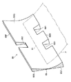
図8は、第2ガイド板88の斜視図である。第2ガイド板88も、左右方向に長い板状の部材からなり、シート搬送路52を通紙される最大サイズのシートPの幅よりも広幅の幅サイズを有する。第2ガイド板88も同様に、樹脂によって形成されることが望ましく、例えばABS樹脂製のものを用いることができる。第2ガイド平面88Gは、第2ガイド板85の上流端縁88Bから下流端縁88Fにかけて、緩やかに凹状に湾曲した湾曲平面である。第2ガイド板88の肉厚は、概ねシート搬送方向の中央部分が薄肉部89とされ、上流端縁88B及び下流端縁88Fの側が厚肉部90A、90Bとされている。つまり、第2ガイド板88の上流端縁88Bから前記中央部分にかけて凹曲面に沿って徐々に肉厚が薄くなり、中央部分から下流端縁88Fにかけて凹曲面に沿って徐々に肉厚が厚くなっている。第2ガイド板88の上流端縁88Bの側には、2組の搬送ローラー対56をシート搬送路52内へ突出させるための切り欠き部881が設けられている。また、下流端縁88Fの側には、検知センサ91をシート搬送路52内へ突出させるための切り欠き部882が設けられている。
FIG. 8 is a perspective view of the
薄肉部89は、搬送ローラー対56によってレジストローラー対57に向けて搬送されるシートP(手差しシートPM)の搬送方向先端Pfが衝突する領域に配置されている。本実施形態におけるシート搬送路52のレイアウトでは、先端Pfが衝突する領域は、第2ガイド板88の概ねシート搬送方向の中央部分なる。このため、薄肉部89は、前記中央部分に配置されている。シートPの先端Pfは、薄肉部89に衝突した後、第2ガイド平面88Gの厚肉部90Bによってガイドされ、停止状態のレジストローラー対57のニップ部N3に突き当たる。その後、搬送ローラー対56によるシートPの搬送が継続されるので、シートPには撓みが生じる。この撓み部が成長して大きくなると、当該撓み部が薄肉部89に衝突することになる。
The thin-
以上の通り、第1ガイド板85及び第2ガイド板88には、シートPの先端Pfが衝突する領域に薄肉部86、89が備えられている。これにより、シートPの衝突により発生する衝撃性音の高周波成分が抑制され、当該衝撃音の音質を改変し、静音化を図ることができる。以下、この点について説明する。
As described above, the
シートのように剛性が低い部材のエッジが、比較的剛性の高い平坦な面に衝突すると、「コツッ」というような衝撃性音が発生する。これは、前記衝突によってシート自身が発する音である。このような衝撃性音には、多くの周波数成分が含まれている。ノイズ全般において、一般に人間がより不快に感じるのは、ノイズに含まれる高周波数成分の音である。従って、非定常性の高い前記衝撃性音に含まれる高周波数成分の音を、構造パラメ−タ(設計因子)の関係性を明らかにして最小化することができれば、ユーザーの不快感も抑制することができる。 When an edge of a member having low rigidity such as a sheet collides with a flat surface having relatively high rigidity, a shocking sound such as “click” is generated. This is a sound generated by the sheet itself due to the collision. Such an impulsive sound includes many frequency components. In general, noise that is generally more unpleasant to humans is high-frequency component sounds contained in noise. Therefore, if the high-frequency component sound included in the impact sound with high non-stationarity can be minimized by clarifying the relationship between the structural parameters (design factors), the user's discomfort is also suppressed. be able to.
衝撃性音が如何なる周波数成分を含むかについては、当該衝撃性音に対してウエーブレット(Wevelet)変換に基づく解析を行うことによって把握することができる。ウエーブレット変換は、シートとガイド板との接触による衝撃性音のような時変する非定常音を、スケール毎(周波数成分)に分解し、その音の特徴を抽出することができる利点がある。 What frequency component the impulsive sound includes can be grasped by performing an analysis based on the wavelet transform on the impulsive sound. Wavelet transform has the advantage that time-varying unsteady sound such as impact sound due to contact between the seat and the guide plate can be decomposed into each scale (frequency component) and the characteristics of the sound can be extracted. .
本発明者は、上記のウエーブレット変換に基づいた衝撃性音の評価を伴った実験の結果、シートとガイド板との衝撃性音に含まれ、衝突角度の変化に依存し、特徴的で、影響度の高い高周波数成分の低減には、シートの先端が衝突する部分においてガイド板を薄肉化が寄与することを見出した。上述した第1ガイド板85及び第2ガイド板88の薄肉部86、89は、当該実験に基づいて得られた構成である。薄肉部86、89は、第1ガイド板85及び第2ガイド板88の他の部分に比較して剛性を低下させるために薄肉化された部分である。例えば、第1ガイド板85及び第2ガイド板88がABS樹脂にて形成されている場合、厚肉部851、90A、90Bの厚さが4mm〜10mm程度であるとすると、薄肉部86、89は1mm〜2mm程度の厚さを有する部分として形成される。1mm厚さのABS樹脂からなる板は、シートPの衝突を充分に受け止めることができる強度及び耐久性を有する。すなわち、薄肉部86、89において剛性を低下させると言っても、容易に変形する程に薄肉化する趣旨ではない。
As a result of the experiment accompanied by the evaluation of the impact sound based on the wavelet transformation described above, the inventor is included in the impact sound of the seat and the guide plate, depends on the change in the collision angle, is characteristic, It has been found that reducing the thickness of the guide plate contributes to the reduction of the high-frequency component having a high influence level at the portion where the leading edge of the sheet collides. The
従来、シートと接触するガイド面は、一般にガイドリブの先端面にて画定されている。すなわち、上記実施形態におけるリブ付きガイド板82のように、基部となるガイド面83からガイドリブ84が立設され、このガイドリブ84の先端にシートが接するガイド板が一般的である。このような一般的なガイド板を、シートの先端が衝突するガイド面に適用した場合、当該ガイド板のシートが衝突する方向の厚さは非常に厚くなる。この場合、衝撃性音の高周波成分を低減することは難しい。
Conventionally, a guide surface that comes into contact with a sheet is generally defined by a tip surface of a guide rib. That is, like the rib-equipped
そこで、本実施形態では、ガイド板(第1ガイド板85及び第2ガイド板88)の、シートの搬送方向先端が衝突する側のガイド面を、ガイドリブ等が存在しない平坦な面(第1ガイド平面85G及び第2ガイド平面88G)としている。第1ガイド平面85G及び第2ガイド平面88Gは、従来のガイドリブの先端によって画定されるガイド面と略同位置に設定される。これに加えて、シートの搬送方向先端が衝突する領域に薄肉部86、89を設けている。かかる工夫によって、衝撃性音の高周波成分は低減される。
Therefore, in the present embodiment, the guide surface of the guide plate (the
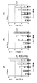
図9は、ABS樹脂製のガイド板のガイド平面にシートの先端を衝突させる実験を行い、このときの衝撃性音の発生状態を示すグラフであって、図9(A)はシートの先端が衝突する領域のガイド板の厚さt=2.5mm、図9(B)はt=2.0mm、図9(C)はt=1.5mmの場合の棒グラフである。各グラフにおいて、横軸はガイド平面に対するシートの入射角θ(図7参照)を示し、縦軸はウエーブレット変換で得られた各レベルのウエーブレット係数のデ−タを2乗和した平均を、エネルギーとして示している。本実験では、シートの線速を300mm/s、シートの入射角θを、30度〜50度まで5度間隔で変更し、各々の場合に発生する衝撃性音を録取した。グラフから明らかな通り、シートの入射角が垂直に近くなる程、全体エネルギーが大きくなることが判る。また、ガイド板の厚さtが薄くなる程、全体エネルギーが小さくなることが判る。 FIG. 9 is a graph showing an impact sound generation state in which an experiment in which the leading edge of the sheet collides with the guide plane of the ABS resin guide plate is shown. FIG. FIG. 9B is a bar graph when the thickness t = 2.5 mm of the guide plate in the collision area, FIG. 9B is t = 2.0 mm, and FIG. 9C is t = 1.5 mm. In each graph, the horizontal axis indicates the incident angle θ of the sheet with respect to the guide plane (see FIG. 7), and the vertical axis indicates an average obtained by summing the squares of the data of the wavelet coefficients at each level obtained by the wavelet transform. Shown as energy. In this experiment, the sheet linear velocity was changed to 300 mm / s, and the sheet incident angle θ was changed from 30 degrees to 50 degrees at intervals of 5 degrees, and impact sound generated in each case was recorded. As is apparent from the graph, it can be seen that as the incident angle of the sheet becomes closer to the vertical, the overall energy increases. It can also be seen that the overall energy decreases as the thickness t of the guide plate decreases.
本実験では、衝撃性音のウエーブレット変換によって、得られた当該衝撃性音の周波数成分を求めた。ここでは、離散ウエーブレット変換による、分解レベル7までの解析を行った。図10に、前記離散ウエーブレット変換で用いたドベシィ8ウエーブレット関数を示す。図9(A)〜(C)において、各棒グラフの内容として分解された低スケ−ル(以後、高周波成分)D1〜PD7を、分解レベル毎のエネルギーで示している。高周波成分D1〜D7のうち、D7が最もシートのガイド板への入射角による衝撃性音への質に対する寄与度が高く、線形的に変化していることがわかる。
In this experiment, the frequency component of the impulsive sound obtained by wavelet conversion of the impulsive sound was obtained. Here, analysis up to
図9(A)〜(C)において、シートの入射角θ=50度の場合を比較すると明らかな通り、レベルD1〜D6についてはさほど変化は認められないものの、高周波成分が支配的なレベルD7の音エネルギーが、ガイド板の厚さt=2.5mm、t=2.0mm、t=1.5mmと減少する程、顕著に低下している。t=1.5mmにおける衝撃性音のエネルギーは、高価な制振樹脂にて形成されたガイド板にシートの先端を衝突させた場合と同レベルまで抑制されたエネルギーである。なお、シートの入射角θ=50度となるシート搬送路は、小型の画像形成装置においてはしばしば採用される湾曲度である。 In FIGS. 9A to 9C, as is apparent from the comparison of the case where the incident angle θ of the sheet is 50 degrees, the level D7 in which the high frequency component is dominant is not observed for the levels D1 to D6. Is significantly reduced as the thickness of the guide plate decreases to t = 2.5 mm, t = 2.0 mm, and t = 1.5 mm. The energy of impact sound at t = 1.5 mm is energy that is suppressed to the same level as when the leading end of the sheet collides with a guide plate made of expensive vibration damping resin. Note that the sheet conveyance path where the incident angle θ of the sheet is 50 degrees is a curvature that is often employed in a small image forming apparatus.
以上の通り、本実施形態のシート搬送装置100によれば、シート搬送路52を搬送されるシートPの搬送方向先端Pfは、リブ等を備えない平面からなる第1ガイド平面85G及び第2ガイド平面88Gであって、これらガイド平面の薄肉部86、89に衝突する。かかる薄肉部86、89にシートPの先端Pfが衝突した場合、上記の実験からサポートされる通り、通常の肉厚を備える部分に比べて衝撃性音の高周波成分が低減される。つまり、シートPの衝突により発生する衝撃性音の特徴的な高周波成分を抑制し、当該衝撃音の音質改善による快音化と、同時にエネルギーの低減による静音化を図ることができる。従って、前記衝撃性音がユーザーに与える不快感を緩和することができる。
As described above, according to the
また、薄肉部86、89を有する第1ガイド平面85G及び第2ガイド平面88Gは、U字状に湾曲したシート搬送路52の外側面を画定している。U字状に湾曲した搬送路の外側面には、シートPの搬送方向先端Pfが強く衝突する傾向がある。このような外側面に、薄肉部86、89を備えた第1ガイド平面85G及び第2ガイド平面88Gが配置されているので、衝撃性音を効果的に抑制することができる。
Further, the
さらに、U字状に湾曲したシート搬送路52の内側面は、凸形状に湾曲された凸ガイド面83を備えたリブ付きガイド板82の前記凸ガイド面83で画定されている。このため、シートPの先端Pfが搬送ローラー対56にニップされた後は、当該シートPは専ら凸ガイド面83(ガイドリブ84)と摺接するようになり、U字状に湾曲したシート搬送路52の外側面を形成する第1ガイド平面85Gとは接触しなくなる。従って、薄肉部86にはシートPの先端Pfのみが専ら接触し、シートPと薄肉部86とは常時接触しない。これにより、シートPとの摺接に起因する薄肉部86の劣化が抑止される。
Further, the inner side surface of the
また、レジストローラー対57の直上流に位置する第2ガイド板88の第2ガイド平面88Gには、シートPの撓み部も接触する。しかし、当該撓み部が接触する部分には薄肉部89が存在する。従って、その衝撃性音の特徴的な高周波成分を低減でき、ユーザーの不快感を抑制することができる。
Further, the bent portion of the sheet P also contacts the
上記実施形態では、本発明を画像形成装置のシート搬送装置に適用した場合について説明した。本発明はこれに限らず、シートを、非直線的な部分を含んで設定されたシート搬送路を通して搬送するシート搬送装置に広く適用することが可能である。 In the above embodiment, the case where the present invention is applied to the sheet conveying apparatus of the image forming apparatus has been described. The present invention is not limited to this, and can be widely applied to a sheet conveying apparatus that conveys a sheet through a sheet conveying path set including a non-linear portion.
1 画像形成装置
100 シート搬送装置
101 給紙ローラー対(搬送手段;第2の搬送ローラー対)
2 装置本体
22 画像形成部
52 シート搬送路
56 搬送ローラー対(搬送手段;第1の搬送ローラー対又は第2の搬送ローラー対)
57 レジストローラー対(搬送手段;第1の搬送ローラー対)
82 リブ付きガイド板(ガイド部材)
83 ガイド面(凸ガイド面)
85 第1ガイド板(ガイド板)
85G 第1ガイド平面
86 薄肉部
88 第2ガイド板(ガイド板)
88G 第2ガイド平面
89 薄肉部
P シート
Pf シートの搬送方向先端
DESCRIPTION OF SYMBOLS 1
2 apparatus main body 22
57 Registration roller pair (conveying means; first conveying roller pair)
82 Guide plate with ribs (guide member)
83 Guide surface (convex guide surface)
85 First guide plate (guide plate)
85G
88G
Claims (7)
非直線的な部分を含んで設定されたシート搬送路と、
前記シート搬送路に配置され、シートを搬送する搬送手段と、
前記シート搬送路の前記非直線的な部分に配置され、シートをガイドするガイド平面を有するガイド板と、を備え、
前記ガイド平面は、ガイドリブが存在しない平坦な面からなり、
前記ガイド板は、前記ガイド平面における前記シート搬送路を搬送されるシートの搬送方向先端のエッジが衝突する領域に、前記衝突により発生する衝撃性音の高周波成分を抑制する薄肉部を備える、シート搬送装置。 A sheet conveying apparatus for conveying a sheet,
A sheet conveyance path set including a non-linear portion;
A conveying means arranged in the sheet conveying path for conveying the sheet;
A guide plate disposed in the non-linear portion of the sheet conveyance path and having a guide plane for guiding the sheet,
The guide plane is a flat surface without guide ribs,
The guide plate includes a thin portion that suppresses a high-frequency component of impact sound generated by the collision in a region where an edge at a front end in a conveyance direction of the sheet conveyed on the sheet conveyance path in the guide plane collides. Conveying device.
前記シート搬送路の前記非直線的な部分は、U字状に湾曲した搬送路であり、
前記ガイド平面は、前記U字状に湾曲した搬送路の外側面を画定している、シート搬送装置。 In the sheet conveying apparatus according to claim 1,
The non-linear part of the sheet conveying path is a U-shaped curved conveying path,
The sheet conveying apparatus, wherein the guide plane defines an outer surface of the conveying path curved in the U shape.
前記搬送手段は、シートをニップして搬送する搬送ローラー対であって、前記シート搬送路の所定位置に配置された第1搬送ローラー対と、前記第1の搬送ローラー対の上流側に配設される第2の搬送ローラー対とを含み、
前記U字状に湾曲した搬送路は、前記第1の搬送ローラー対と前記第2の搬送ローラー対との間に配設されている、シート搬送装置。 In the sheet conveying apparatus according to claim 2,
The conveying means is a pair of conveying rollers that nip and convey a sheet, and is disposed upstream of the first conveying roller pair disposed at a predetermined position of the sheet conveying path and the first conveying roller pair. And a second pair of transport rollers
The U-shaped curved conveying path is a sheet conveying apparatus disposed between the first conveying roller pair and the second conveying roller pair.
前記U字状に湾曲した搬送路の内側面は、凸形状に湾曲された凸ガイド面を備えたガイド部材の前記凸ガイド面で画定され、
前記U字状に湾曲した搬送路の外側面は、前記ガイド板のガイド平面で画定されている、シート搬送装置。 In the sheet conveying apparatus according to claim 3,
An inner surface of the U-shaped curved conveyance path is defined by the convex guide surface of a guide member having a convex guide surface curved in a convex shape,
The sheet conveying apparatus, wherein an outer surface of the U-shaped curved conveyance path is defined by a guide plane of the guide plate.
前記第1搬送ローラー対が、シートの搬送を一時的に中断する搬送ローラー対であって、シートが前記第1搬送ローラー対の上流に撓んだ状態で一時的に待機するものであり、
前記ガイド板の前記薄肉部には、シートの撓み部も接触する、シート搬送装置。 In the sheet conveying apparatus according to claim 3,
The first conveyance roller pair is a conveyance roller pair that temporarily interrupts conveyance of the sheet, and temporarily waits in a state where the sheet is bent upstream of the first conveyance roller pair,
The sheet conveying apparatus, wherein the thin portion of the guide plate is also in contact with a bent portion of the sheet.
前記ガイド板は、前記薄肉部の搬送方向下流側に厚肉部を備え、前記厚肉部の背面には前記シート搬送路に合流するシートをガイドする背面ガイドが形成されている、シート搬送装置。 The guide plate includes a thick part on the downstream side in the transport direction of the thin part, and a back guide for guiding a sheet that joins the sheet transport path is formed on the back of the thick part. .
前記画像形成部を経由してシートを搬送する請求項1〜6のいずれかに記載のシート搬送装置と、
を備えることを特徴とする画像形成装置。 An image forming unit for forming an image on a sheet;
The sheet conveying apparatus according to any one of claims 1 to 6 , which conveys a sheet via the image forming unit,
An image forming apparatus comprising:
Priority Applications (4)
| Application Number | Priority Date | Filing Date | Title |
|---|---|---|---|
| JP2012206927A JP5750418B2 (en) | 2012-09-20 | 2012-09-20 | Sheet conveying apparatus and image forming apparatus provided with the same |
| CN201310428276.5A CN103662895B (en) | 2012-09-20 | 2013-09-18 | Sheet conveying device and possess the image processing system of this device |
| EP13004579.2A EP2711319B1 (en) | 2012-09-20 | 2013-09-19 | Sheet conveying device and image forming apparatus including sheet conveying device |
| US14/031,350 US9290345B2 (en) | 2012-09-20 | 2013-09-19 | Sheet conveying device and image forming apparatus including sheet conveying device |
Applications Claiming Priority (1)
| Application Number | Priority Date | Filing Date | Title |
|---|---|---|---|
| JP2012206927A JP5750418B2 (en) | 2012-09-20 | 2012-09-20 | Sheet conveying apparatus and image forming apparatus provided with the same |
Publications (2)
| Publication Number | Publication Date |
|---|---|
| JP2014061961A JP2014061961A (en) | 2014-04-10 |
| JP5750418B2 true JP5750418B2 (en) | 2015-07-22 |
Family
ID=49301245
Family Applications (1)
| Application Number | Title | Priority Date | Filing Date |
|---|---|---|---|
| JP2012206927A Expired - Fee Related JP5750418B2 (en) | 2012-09-20 | 2012-09-20 | Sheet conveying apparatus and image forming apparatus provided with the same |
Country Status (4)
| Country | Link |
|---|---|
| US (1) | US9290345B2 (en) |
| EP (1) | EP2711319B1 (en) |
| JP (1) | JP5750418B2 (en) |
| CN (1) | CN103662895B (en) |
Families Citing this family (7)
| Publication number | Priority date | Publication date | Assignee | Title |
|---|---|---|---|---|
| JP5994535B2 (en) * | 2012-09-28 | 2016-09-21 | スター精密株式会社 | Paper transport mechanism of printing device |
| JP6116338B2 (en) * | 2013-04-25 | 2017-04-19 | キヤノン株式会社 | Image forming apparatus |
| JP6245110B2 (en) * | 2014-08-13 | 2017-12-13 | 京セラドキュメントソリューションズ株式会社 | Sheet conveying apparatus and image forming apparatus provided with the same |
| US9791814B2 (en) * | 2015-04-09 | 2017-10-17 | Canon Kabushiki Kaisha | Image forming apparatus |
| JP6330728B2 (en) * | 2015-05-25 | 2018-05-30 | 京セラドキュメントソリューションズ株式会社 | Image forming apparatus |
| JP6531771B2 (en) | 2017-03-28 | 2019-06-19 | コニカミノルタ株式会社 | Image reading apparatus and image forming apparatus |
| JP2023068553A (en) * | 2021-11-02 | 2023-05-17 | 富士フイルムビジネスイノベーション株式会社 | Sheet conveyance device and image forming apparatus |
Family Cites Families (25)
| Publication number | Priority date | Publication date | Assignee | Title |
|---|---|---|---|---|
| DE4421611C2 (en) * | 1993-06-21 | 1999-01-14 | Gold Star Co | Laser beam printer |
| JP3827026B2 (en) | 1996-03-04 | 2006-09-27 | シャープ株式会社 | Paper transport device |
| JP3290886B2 (en) * | 1996-04-25 | 2002-06-10 | キヤノン株式会社 | Sheet material transport device |
| JP3616460B2 (en) * | 1996-07-17 | 2005-02-02 | シャープ株式会社 | Sheet transport device |
| JPH10129883A (en) * | 1996-10-30 | 1998-05-19 | Canon Inc | Sheet feeding apparatus and image forming apparatus |
| JP3762849B2 (en) * | 1999-06-15 | 2006-04-05 | 株式会社リコー | Sheet guide device |
| JP3774613B2 (en) * | 2000-02-29 | 2006-05-17 | キヤノン株式会社 | Recording device |
| JP3653473B2 (en) | 2001-02-16 | 2005-05-25 | 京セラミタ株式会社 | Image forming apparatus |
| JP2003246490A (en) * | 2002-02-20 | 2003-09-02 | Ricoh Co Ltd | Sheet conveying device, image forming device, and image reading device |
| JP2006016094A (en) | 2004-06-30 | 2006-01-19 | Konica Minolta Business Technologies Inc | Paper sheet conveying device of image forming device |
| JP4467456B2 (en) * | 2005-03-31 | 2010-05-26 | 京セラミタ株式会社 | Paper transport mechanism of image forming apparatus |
| JP2007106551A (en) * | 2005-10-13 | 2007-04-26 | Ricoh Co Ltd | RECORDING MEDIUM CONVEYING DEVICE, SCANNER DEVICE, AND IMAGE FORMING DEVICE |
| US7802786B2 (en) * | 2007-01-30 | 2010-09-28 | Lite-On Technology Corp. | Duplex automatic document feeder and duplex document scanning method using the same |
| JP5202074B2 (en) * | 2007-04-13 | 2013-06-05 | 京セラドキュメントソリューションズ株式会社 | Sheet conveying apparatus and image forming apparatus provided with the same |
| EP2250027A4 (en) | 2008-03-05 | 2011-03-30 | Silverbrook Res Pty Ltd | Sheet feed assembly defining curved and straight feed path |
| JP4715929B2 (en) * | 2009-01-29 | 2011-07-06 | ブラザー工業株式会社 | Image forming apparatus and sheet conveying apparatus |
| US20100225054A1 (en) * | 2009-03-03 | 2010-09-09 | Silverbrook Research Pty Ltd | Sheet feed assembly defining curved and straight feed path |
| JP2011042464A (en) * | 2009-08-21 | 2011-03-03 | Canon Inc | Sheet carrying device |
| JP5187290B2 (en) * | 2009-09-14 | 2013-04-24 | 富士ゼロックス株式会社 | Guiding device and image forming apparatus |
| JP2011105479A (en) * | 2009-11-19 | 2011-06-02 | Konica Minolta Business Technologies Inc | Paper carrying device and image forming device |
| JP6010959B2 (en) * | 2012-03-26 | 2016-10-19 | ブラザー工業株式会社 | Sheet conveying apparatus and image recording apparatus |
| JP5787854B2 (en) * | 2012-09-21 | 2015-09-30 | 京セラドキュメントソリューションズ株式会社 | Sheet conveying apparatus and image forming apparatus |
| JP5942744B2 (en) * | 2012-09-26 | 2016-06-29 | ブラザー工業株式会社 | Sheet conveying mechanism and image forming apparatus |
| JP5942758B2 (en) * | 2012-09-28 | 2016-06-29 | ブラザー工業株式会社 | Sheet conveying apparatus and inkjet recording apparatus |
| US9280118B2 (en) * | 2013-10-09 | 2016-03-08 | Canon Kabushiki Kaisha | Image forming apparatus |
-
2012
- 2012-09-20 JP JP2012206927A patent/JP5750418B2/en not_active Expired - Fee Related
-
2013
- 2013-09-18 CN CN201310428276.5A patent/CN103662895B/en not_active Expired - Fee Related
- 2013-09-19 US US14/031,350 patent/US9290345B2/en not_active Expired - Fee Related
- 2013-09-19 EP EP13004579.2A patent/EP2711319B1/en not_active Not-in-force
Also Published As
| Publication number | Publication date |
|---|---|
| EP2711319A3 (en) | 2014-04-02 |
| CN103662895A (en) | 2014-03-26 |
| EP2711319A2 (en) | 2014-03-26 |
| US9290345B2 (en) | 2016-03-22 |
| JP2014061961A (en) | 2014-04-10 |
| US20140077443A1 (en) | 2014-03-20 |
| EP2711319B1 (en) | 2016-11-16 |
| CN103662895B (en) | 2016-11-23 |
Similar Documents
| Publication | Publication Date | Title |
|---|---|---|
| JP5750418B2 (en) | Sheet conveying apparatus and image forming apparatus provided with the same | |
| JP5202074B2 (en) | Sheet conveying apparatus and image forming apparatus provided with the same | |
| JP2011178494A (en) | Image forming apparatus | |
| JP4873487B2 (en) | Image forming apparatus | |
| JP2009078887A (en) | Paper feeding device and image forming apparatus | |
| EP2703323A2 (en) | Conveying guide, sheet conveying apparatus, and image forming apparatus | |
| JP2019043718A (en) | Sheet feeding apparatus and image forming apparatus | |
| JP2004029271A (en) | Image forming apparatus | |
| JP5316081B2 (en) | Image forming apparatus | |
| JP5634143B2 (en) | Sheet conveying apparatus and image forming apparatus | |
| JP2017088300A (en) | Sheet conveying apparatus and image forming apparatus provided with the same | |
| JP5980052B2 (en) | Sheet conveying apparatus and image forming apparatus | |
| JP5663508B2 (en) | Sheet conveying apparatus and image forming apparatus including the same | |
| JP2018070289A (en) | Sheet discharge device and image formation forming apparatus | |
| JP4356631B2 (en) | Sheet conveying apparatus and image forming apparatus provided with the same | |
| JP2015086039A (en) | Sheet feeding apparatus and image forming apparatus | |
| JP2007230746A (en) | Image forming device | |
| JP5817478B2 (en) | Paper feeding and conveying apparatus and image forming apparatus | |
| JP2010089900A (en) | Sheet carrying device, sheet length detecting device and image forming device | |
| US20100327521A1 (en) | Image forming apparatus | |
| JP2013075740A (en) | Sheet conveying device and image forming apparatus | |
| JP2016166065A (en) | Sheet conveyance device and image formation apparatus having the same | |
| JP2005350244A (en) | Paper feeding device | |
| JP2011195275A (en) | Image forming device and relay unit | |
| JP2011013375A (en) | Image forming apparatus |
Legal Events
| Date | Code | Title | Description |
|---|---|---|---|
| A621 | Written request for application examination |
Free format text: JAPANESE INTERMEDIATE CODE: A621 Effective date: 20140819 |
|
| A977 | Report on retrieval |
Free format text: JAPANESE INTERMEDIATE CODE: A971007 Effective date: 20141208 |
|
| A131 | Notification of reasons for refusal |
Free format text: JAPANESE INTERMEDIATE CODE: A131 Effective date: 20141217 |
|
| A521 | Request for written amendment filed |
Free format text: JAPANESE INTERMEDIATE CODE: A523 Effective date: 20150212 |
|
| TRDD | Decision of grant or rejection written | ||
| A01 | Written decision to grant a patent or to grant a registration (utility model) |
Free format text: JAPANESE INTERMEDIATE CODE: A01 Effective date: 20150421 |
|
| A61 | First payment of annual fees (during grant procedure) |
Free format text: JAPANESE INTERMEDIATE CODE: A61 Effective date: 20150518 |
|
| R150 | Certificate of patent or registration of utility model |
Ref document number: 5750418 Country of ref document: JP Free format text: JAPANESE INTERMEDIATE CODE: R150 |
|
| LAPS | Cancellation because of no payment of annual fees |