JP6521018B2 - Refrigeration system - Google Patents
Refrigeration system Download PDFInfo
- Publication number
- JP6521018B2 JP6521018B2 JP2017190766A JP2017190766A JP6521018B2 JP 6521018 B2 JP6521018 B2 JP 6521018B2 JP 2017190766 A JP2017190766 A JP 2017190766A JP 2017190766 A JP2017190766 A JP 2017190766A JP 6521018 B2 JP6521018 B2 JP 6521018B2
- Authority
- JP
- Japan
- Prior art keywords
- heat exchanger
- refrigerant
- pipe
- refrigeration
- side heat
- Prior art date
- Legal status (The legal status is an assumption and is not a legal conclusion. Google has not performed a legal analysis and makes no representation as to the accuracy of the status listed.)
- Active
Links
Images


Classifications
-
- F—MECHANICAL ENGINEERING; LIGHTING; HEATING; WEAPONS; BLASTING
- F25—REFRIGERATION OR COOLING; COMBINED HEATING AND REFRIGERATION SYSTEMS; HEAT PUMP SYSTEMS; MANUFACTURE OR STORAGE OF ICE; LIQUEFACTION SOLIDIFICATION OF GASES
- F25B—REFRIGERATION MACHINES, PLANTS OR SYSTEMS; COMBINED HEATING AND REFRIGERATION SYSTEMS; HEAT PUMP SYSTEMS
- F25B1/00—Compression machines, plants or systems with non-reversible cycle
-
- F—MECHANICAL ENGINEERING; LIGHTING; HEATING; WEAPONS; BLASTING
- F25—REFRIGERATION OR COOLING; COMBINED HEATING AND REFRIGERATION SYSTEMS; HEAT PUMP SYSTEMS; MANUFACTURE OR STORAGE OF ICE; LIQUEFACTION SOLIDIFICATION OF GASES
- F25B—REFRIGERATION MACHINES, PLANTS OR SYSTEMS; COMBINED HEATING AND REFRIGERATION SYSTEMS; HEAT PUMP SYSTEMS
- F25B29/00—Combined heating and refrigeration systems, e.g. operating alternately or simultaneously
-
- F—MECHANICAL ENGINEERING; LIGHTING; HEATING; WEAPONS; BLASTING
- F25—REFRIGERATION OR COOLING; COMBINED HEATING AND REFRIGERATION SYSTEMS; HEAT PUMP SYSTEMS; MANUFACTURE OR STORAGE OF ICE; LIQUEFACTION SOLIDIFICATION OF GASES
- F25B—REFRIGERATION MACHINES, PLANTS OR SYSTEMS; COMBINED HEATING AND REFRIGERATION SYSTEMS; HEAT PUMP SYSTEMS
- F25B6/00—Compression machines, plants or systems, with several condenser circuits
- F25B6/02—Compression machines, plants or systems, with several condenser circuits arranged in parallel
Description
本発明は、冷凍装置に関する。 The present invention relates to a refrigeration system.
従来より、冷媒回路を備えた冷凍装置が知られている。 Conventionally, a refrigeration system provided with a refrigerant circuit is known.
特許文献1に開示された冷凍装置は、圧縮機及び熱源側熱交換器を有する熱源ユニットと、利用側熱交換器をそれぞれ有する利用ユニットとが連絡配管で接続される。複数の利用ユニットは、例えば空調ユニットと、複数の冷設ユニットとで構成される。この冷凍装置では、空調ユニットによって暖房が行われると同時に、冷設ユニットによって庫内の冷蔵/冷凍が行われる。
In the refrigeration apparatus disclosed in
より詳細には、この冷凍装置のある運転では、圧縮機で圧縮された冷媒が、空調ユニットの室内熱交換器(第1利用側熱交換器)と、室外熱交換器(熱源側熱交換器)とに送られ、両者で凝縮する。凝縮後の冷媒は、複数の冷設ユニットの熱交換器(第2利用側熱交換器)で蒸発し、圧縮機で再び圧縮される。つまり、この運転では、熱源側熱交換器と第1利用側熱交換器とが凝縮器となり、第2利用側熱交換器が蒸発器となる冷凍サイクルが行われる。 More specifically, in an operation with this refrigeration system, the refrigerant compressed by the compressor is the indoor heat exchanger (first use side heat exchanger) of the air conditioning unit and the outdoor heat exchanger (heat source side heat exchanger) ) And condense with both. The condensed refrigerant is evaporated in the heat exchangers (second use side heat exchangers) of the plurality of cold units, and compressed again in the compressor. That is, in this operation, a refrigeration cycle is performed in which the heat source side heat exchanger and the first usage side heat exchanger become a condenser and the second usage side heat exchanger becomes an evaporator.
上記の運転では、熱源側熱交換器と第1利用側熱交換器との双方が凝縮器となる。このため、これらの凝縮器の内部に液冷媒が溜まっていくと、第2利用側熱交換器に送られる冷媒の量を十分に確保できなくなる可能性がある。従って、例えば冷設ユニットにおける冷媒の蒸発量が不足し、冷設ユニットの冷却能力が低下してしまうという問題が生じる。 In the above operation, both the heat source side heat exchanger and the first usage side heat exchanger become the condenser. For this reason, when the liquid refrigerant is accumulated inside these condensers, there is a possibility that the amount of the refrigerant sent to the second usage-side heat exchanger can not be sufficiently secured. Therefore, for example, the amount of evaporation of the refrigerant in the cooling unit runs short, and the problem arises that the cooling capacity of the cooling unit is reduced.
本発明は、このような課題に着目したものであり、その目的は、熱源側熱交換器及び第1利用側熱交換器における液冷媒の溜まり込みを抑制できる冷凍装置を提供することである。 This invention pays attention to such a subject, The objective is to provide the freezing apparatus which can suppress the retention of the liquid refrigerant in a heat source side heat exchanger and a 1st utilization side heat exchanger.
第1の発明は、圧縮機(13a,13b,13c)、熱源側熱交換器(12)、第1利用側熱交換器(22)、第2利用側熱交換器(32,42)が接続される冷媒回路(2)を備え、前記熱源側熱交換器(12)及び前記第1利用側熱交換器(22)で冷媒がそれぞれ凝縮し且つ前記第2利用側熱交換器(32,42)で冷媒が蒸発する運転が可能な冷凍装置であって、前記冷媒回路(2)には、前記熱源側熱交換器(12)の流出側に設けられる第1流量調節弁(14)と、前記第1利用側熱交換器(22)の流出側に設けられる第2流量調節弁(23)とが接続され、前記運転中に前記熱源側熱交換器(12)及び第1利用側熱交換器(22)に溜まった液冷媒の量を示す指標に基づいて各流量調節弁(14,23)の開度を調節する制御部(100)とを備え、前記冷媒回路(2)には、蒸発器としての第2利用側熱交換器(32,42)の流入側に膨張弁(33,43)が接続され、前記制御部(100)は、前記運転中に前記膨張弁(33,43)の前後の圧力差(ΔP)が所定値よりも低い条件が成立すると、前記膨張弁(33,43)の流入側の冷媒の圧力を増大させることを特徴とする冷凍装置である。 In the first invention, the compressor (13a, 13b, 13c), the heat source side heat exchanger (12), the first use side heat exchanger (22), and the second use side heat exchanger (32, 42) are connected The heat source side heat exchanger (12) and the first usage side heat exchanger (22) to condense the refrigerant and the second usage side heat exchanger (32, 42) And the refrigerant circuit (2) is provided with a first flow control valve (14) provided on the outflow side of the heat source side heat exchanger (12). A second flow control valve (23) provided on the outflow side of the first use side heat exchanger (22) is connected, and the heat source side heat exchanger (12) and the first use side heat exchange are connected during the operation Control unit (100) for adjusting the opening degree of each flow rate control valve (14, 23) based on an index indicating the amount of liquid refrigerant accumulated in the vessel (22), the refrigerant circuit (2) comprising Second interest as an evaporator Expansion valve (33, 43) is connected to the inflow side of the heat exchanger (32, 42), and the control unit (100) controls the pressure difference before and after the expansion valve (33, 43) during the operation. When the condition in which (ΔP) is lower than a predetermined value is satisfied, the pressure of the refrigerant on the inflow side of the expansion valve (33, 43) is increased .
第1の発明では、圧縮機(13a,13b,13c)で圧縮された冷媒が、熱源側熱交換器(12)及び第1利用側熱交換器(22)でそれぞれ放熱し凝縮する。凝縮した冷媒は、第2利用側熱交換器(32,42)で蒸発し、圧縮機(13a,13b,13c)に吸入される。この運転において、制御部(100)は、熱源側熱交換器(12)及び第1利用側熱交換器(22)に溜まった液冷媒の量を示す指標に基づいて、各流量調節弁(14,23)の開度を調節する。 In the first invention, the refrigerant compressed by the compressors (13a, 13b, 13c) radiates heat and condenses in the heat source side heat exchanger (12) and the first usage side heat exchanger (22), respectively. The condensed refrigerant is evaporated in the second use side heat exchanger (32, 42) and is sucked into the compressor (13a, 13b, 13c). In this operation, the control unit (100) controls each flow rate control valve (14) based on the index indicating the amount of liquid refrigerant accumulated in the heat source side heat exchanger (12) and the first usage side heat exchanger (22). , 23) adjust the opening degree.
具体的に、上記の指標により、熱源側熱交換器(12)及び第1利用側熱交換器(22)のうちのどちらが、液冷媒が溜まっている傾向にあるかを把握できる。このため、例えば熱源側熱交換器(12)の液冷媒の量や熱交換器全体に占める液冷媒の割合が大きいときには、熱源側熱交換器(12)を流れる冷媒の流量が増大するように各流量調節弁(14,23)の開度を調節する。これにより、熱源側熱交換器(12)での液冷媒の溜まり込みを回避できる。同様に、例えば第1利用側熱交換器(22)の液冷媒の量や熱交換器全体に占める液冷媒の割合が大きいときには、第1利用側熱交換器(22)を流れる冷媒の流量が増大するように各流量調節弁(14,23)の開度を調節する。これにより、第1利用側熱交換器(22)での液冷媒の溜まり込みを回避できる。 Specifically, it is possible to grasp which of the heat source side heat exchanger (12) and the first usage side heat exchanger (22) tends to have the liquid refrigerant accumulated, by the above-mentioned index. Therefore, for example, when the amount of liquid refrigerant in the heat source side heat exchanger (12) or the ratio of the liquid refrigerant to the entire heat exchanger is large, the flow rate of the refrigerant flowing through the heat source side heat exchanger (12) increases. Adjust the opening of each flow control valve (14, 23). Thereby, the accumulation of the liquid refrigerant in the heat source side heat exchanger (12) can be avoided. Similarly, for example, when the amount of liquid refrigerant in the first use side heat exchanger (22) or the ratio of liquid refrigerant to the entire heat exchanger is large, the flow rate of the refrigerant flowing through the first use side heat exchanger (22) is Adjust the opening of each flow control valve (14, 23) to increase. Thereby, the accumulation of the liquid refrigerant in the first usage-side heat exchanger (22) can be avoided.
以上の制御により、第2利用側熱交換器(32,42)へ供給される冷媒の量を確保できる。従って、第2利用側熱交換器(32,42)の冷却能力の低下を回避できる。 By the above control, the amount of the refrigerant supplied to the second usage side heat exchanger (32, 42) can be secured. Therefore, a reduction in the cooling capacity of the second usage-side heat exchanger (32, 42) can be avoided.
第1の発明では、上記のように各流量調節弁(14,23)の開度を調節することに起因して、膨張弁(33,43)の前後の差圧が小さくなると、膨張弁(33,43)の流入側の冷媒の圧力を増大する制御が行われる。つまり、各流量調節弁(14,23)の開度が比較的小さい条件下で運転が行われると、膨張弁(33,43)の流入側の圧力が比較的小さくなり、該膨張弁(33,43)を通過するための冷媒の差圧を確保できない可能性がある。そうすると、蒸発器となる第2利用側熱交換器(32,42)に冷媒を送ることができず、第2利用側熱交換器(32,42)の冷却能力が低下する。 In the first aspect of the invention, when the differential pressure before and after the expansion valve (33, 43) decreases due to the adjustment of the opening degree of each flow rate control valve (14, 23) as described above, the expansion valve ( Control is performed to increase the pressure of the refrigerant on the inflow side of 33, 43). That is, when the operation is performed under the condition that the opening degree of each flow rate control valve (14, 23) is relatively small, the pressure on the inflow side of the expansion valve (33, 43) becomes relatively small, and the expansion valve (33) , 43) may not be secured. Then, the refrigerant can not be sent to the second usage side heat exchanger (32, 42) serving as the evaporator, and the cooling capacity of the second usage side heat exchanger (32, 42) decreases.
これに対し、本発明では、膨張弁(33,43)の前後の圧力差(ΔP)が所定値より低い条件が成立すると、制御部(100)が膨張弁(33,43)の流入側の圧力を上昇させる制御を行う。これにより、膨張弁(33,43)の前後の圧力差を確保でき、冷媒を第2利用側熱交換器(32,42)へ確実に送ることができる。 On the other hand, in the present invention, when the pressure difference (ΔP) before and after the expansion valve (33, 43) is lower than a predetermined value, the control unit (100) controls the inflow side of the expansion valve (33, 43). Control to raise the pressure. Thereby, the pressure difference before and behind the expansion valve (33, 43) can be secured, and the refrigerant can be reliably sent to the second usage-side heat exchanger (32, 42).
第2の発明は、第1の発明において、前記制御部(100)は、前記熱源側熱交換器(12)及び前記第1利用側熱交換器(22)を流出する冷媒の過冷却度(SC1,SC2)を前記指標として用いるとともに、前記熱源側熱交換器(12)及び前記第1利用側熱交換器(22)のうち前記過冷却度(SC1,SC2)が大きい方に対応する流量調節弁(14,23)の開度を大きくする制御と、前記熱源側熱交換器(12)及び前記第1利用側熱交換器(22)のうち前記過冷却度(SC1,SC2)が小さい方に対応する流量調節弁(14,23)の開度を小さくする制御との少なくとも一方の制御を行うことを特徴とする冷凍装置である。 A second aspect of the invention relates to the first aspect of the invention, wherein the control unit (100) measures the degree of subcooling of the refrigerant flowing out of the heat source side heat exchanger (12) and the first usage side heat exchanger (22). The flow rate corresponding to the larger one of the heat source side heat exchanger (12) and the first usage side heat exchanger (22) with the degree of supercooling (SC1, SC2), while using SC1, SC2) as the index Control to increase the opening degree of the control valve (14, 23), and the subcooling degree (SC1, SC2) of the heat source side heat exchanger (12) and the first use side heat exchanger (22) is smaller At least one of the control for reducing the opening degree of the flow rate control valve (14, 23) corresponding to the flow rate control valve (14, 23).
第2の発明の制御部(100)は、熱源側熱交換器(12)及び第1利用側熱交換器(22)をそれぞれ流出する冷媒の過冷却度(SC1,SC2)を用いる。つまり、冷媒の過冷却度(SC1,SC2)は、熱交換器に溜まり込む液冷媒の量や熱交換器全体に占める液冷媒の割合が多くなると大きくなる。従って、冷媒の過冷却度(SC1,SC2)は、熱源側熱交換器(12)や第1利用側熱交換器(22)に溜まった冷媒の量を示す指標となる。 The control unit (100) of the second invention uses the subcooling degree (SC1, SC2) of the refrigerant flowing out of the heat source side heat exchanger (12) and the first usage side heat exchanger (22). That is, the degree of subcooling (SC1, SC2) of the refrigerant increases as the amount of liquid refrigerant accumulated in the heat exchanger and the ratio of liquid refrigerant to the entire heat exchanger increase. Therefore, the degree of subcooling of the refrigerant (SC1, SC2) is an index indicating the amount of refrigerant accumulated in the heat source side heat exchanger (12) and the first usage side heat exchanger (22).
例えば熱源側熱交換器(12)に対応する冷媒の過冷却度(SC1)が、第1利用側熱交換器(22)に対応する冷媒の過冷却度(SC2)よりも大きい場合、熱源側熱交換器(12)の方に多くの液冷媒が溜まっていると判断できる。そこで、この場合、制御部(100)は、第1流量調節弁(14)の開度を大きくする、又は第2流量調節弁(23)の開度を小さくする、又は両者を同時に行う制御を行う。これにより、熱源側熱交換器(12)を流れる冷媒の流量を増大できるので、該熱源側熱交換器(12)での冷媒の溜まり込みを抑制できる。 For example, when the degree of subcooling (SC1) of the refrigerant corresponding to the heat source side heat exchanger (12) is larger than the degree of subcooling (SC2) of the refrigerant corresponding to the first usage side heat exchanger (22), the heat source side It can be determined that a large amount of liquid refrigerant has accumulated in the heat exchanger (12). Therefore, in this case, the control unit (100) increases the opening degree of the first flow control valve (14), reduces the opening degree of the second flow control valve (23), or performs control for performing both simultaneously. Do. Thus, the flow rate of the refrigerant flowing through the heat source side heat exchanger (12) can be increased, so that the accumulation of the refrigerant in the heat source side heat exchanger (12) can be suppressed.
例えば第1利用側熱交換器(22)に対応する冷媒の過冷却度(SC2)が、熱源側熱交換器(12)に対応する冷媒の過冷却度(SC1)よりも大きい場合、第1利用側熱交換器(22)の方に多くの液冷媒が溜まっていると判断できる。そこで、この場合、制御部(100)は、第2流量調節弁(23)の開度を大きくする、又は第1流量調節弁(14)の開度を小さくする、又は両者を同時に行う制御を行う。これにより、第1利用側熱交換器(22)を流れる冷媒の流量を増大できるので、該第1利用側熱交換器(22)での冷媒の溜まり込みを抑制できる。 For example, when the degree of subcooling (SC2) of the refrigerant corresponding to the first use side heat exchanger (22) is larger than the degree of subcooling (SC1) of the refrigerant corresponding to the heat source side heat exchanger (12), the first It can be determined that a large amount of liquid refrigerant is accumulated in the use side heat exchanger (22). Therefore, in this case, the control unit (100) increases the opening degree of the second flow control valve (23), reduces the opening degree of the first flow control valve (14), or performs control to perform both simultaneously. Do. Thus, the flow rate of the refrigerant flowing through the first usage-side heat exchanger (22) can be increased, so that the accumulation of the refrigerant in the first usage-side heat exchanger (22) can be suppressed.
第3の発明は、第1の発明において、前記制御部(100)は、前記熱源側熱交換器(12)及び前記第1利用側熱交換器(22)を流出する冷媒の温度(T1,T2)を前記指標として用いるとともに、前記熱源側熱交換器(12)及び前記第1利用側熱交換器(22)のうち前記冷媒の温度(T1,T2)が低い方に対応する流量調節弁(14,23)の開度を大きくする制御と、前記熱源側熱交換器(12)及び前記第1利用側熱交換器(22)のうち前記冷媒の温度(T1,T2)が高い方に対応する流量調節弁(14,23)の開度を小さくする制御との少なくとも一方の制御を行うことを特徴とする冷凍装置である。 In a third invention according to the first invention, the controller (100) controls the temperature (T1, T1) of the refrigerant flowing out of the heat source side heat exchanger (12) and the first usage side heat exchanger (22). T2) is used as the index, and a flow control valve corresponding to one of the heat source side heat exchanger (12) and the first usage side heat exchanger (22) having a lower temperature (T1, T2) of the refrigerant (14, 23) to increase the opening degree of the heat source side heat exchanger (12) and the first use side heat exchanger (22), the temperature (T1, T2) of the refrigerant is higher It is a freezing apparatus characterized by performing at least one control with control which makes an opening of corresponding flow control valve (14, 23) small.
第3の発明の制御部(100)は、熱源側熱交換器(12)及び第1利用側熱交換器(22)をそれぞれ流出する冷媒の温度(T1,T2)を用いる。熱源側熱交換器(12)及び第1利用側熱交換器(22)の冷媒の凝縮温度は、冷媒回路(2)の高圧に相当する飽和温度であり、両者は等しいとみなすことができる。このため、各冷媒の温度(T1,T2)は、冷媒の過冷却度を間接的に示す指標となる。即ち、冷媒の温度(T1,T2)が小さいということは、過冷却度が大きいことを意味し、熱交換器に液冷媒が多く溜まっていると判断できる。 The control unit (100) of the third invention uses the temperatures (T1, T2) of the refrigerant flowing out of the heat source side heat exchanger (12) and the first usage side heat exchanger (22). The condensation temperatures of the refrigerants of the heat source side heat exchanger (12) and the first usage side heat exchanger (22) are saturation temperatures corresponding to the high pressure of the refrigerant circuit (2), and both can be regarded as equal. For this reason, the temperature (T1, T2) of each refrigerant is an index indirectly indicating the degree of subcooling of the refrigerant. That is, the fact that the temperature (T1, T2) of the refrigerant is small means that the degree of subcooling is large, and it can be judged that a large amount of liquid refrigerant is accumulated in the heat exchanger.
例えば熱源側熱交換器(12)に対応する冷媒の温度(T1)が、第1利用側熱交換器(22)に対応する冷媒の温度(T2)よりも小さい場合、熱源側熱交換器(12)を流出する冷媒の過冷却度が大きく、熱源側熱交換器(12)の液冷媒の量が大きいと判断できる。そこで、この場合、制御部(100)は、第1流量調節弁(14)の開度を大きくする、又は第2流量調節弁(23)の開度を小さくする、又は両者を同時に行う制御を行う。これにより、熱源側熱交換器(12)を流れる冷媒の流量を増大できるので、該熱源側熱交換器(12)での冷媒の溜まり込みを抑制できる。 For example, if the temperature (T1) of the refrigerant corresponding to the heat source side heat exchanger (12) is smaller than the temperature (T2) of the refrigerant corresponding to the first usage side heat exchanger (22) It can be judged that the degree of supercooling of the refrigerant flowing out of 12) is large, and the amount of liquid refrigerant in the heat source side heat exchanger (12) is large. Therefore, in this case, the control unit (100) increases the opening degree of the first flow control valve (14), reduces the opening degree of the second flow control valve (23), or performs control for performing both simultaneously. Do. Thus, the flow rate of the refrigerant flowing through the heat source side heat exchanger (12) can be increased, so that the accumulation of the refrigerant in the heat source side heat exchanger (12) can be suppressed.
例えば第1利用側熱交換器(22)に対応する冷媒の温度(T2)が、熱源側熱交換器(12)に対応する冷媒の温度(T1)よりも小さい場合、第1利用側熱交換器(22)を流出する冷媒の過冷却度が大きく、第1利用側熱交換器(22)の液冷媒の量が大きいと判断できる。そこで、この場合、制御部(100)は、第2流量調節弁(23)の開度を大きくする、又は第1流量調節弁(14)の開度を小さくする、又は両者を同時に行う制御を行う。これにより、第1利用側熱交換器(22)を流れる冷媒の流量を増大できるので、該第1利用側熱交換器(22)での冷媒の溜まり込みを抑制できる。 For example, when the temperature (T2) of the refrigerant corresponding to the first use side heat exchanger (22) is smaller than the temperature (T1) of the refrigerant corresponding to the heat source side heat exchanger (12), the first use side heat exchange It can be judged that the degree of subcooling of the refrigerant flowing out of the vessel (22) is large, and the amount of liquid refrigerant in the first usage-side heat exchanger (22) is large. Therefore, in this case, the control unit (100) increases the opening degree of the second flow control valve (23), reduces the opening degree of the first flow control valve (14), or performs control to perform both simultaneously. Do. Thus, the flow rate of the refrigerant flowing through the first usage-side heat exchanger (22) can be increased, so that the accumulation of the refrigerant in the first usage-side heat exchanger (22) can be suppressed.
第4の発明は、第1乃至3のいずれか1つの発明において、前記熱源側熱交換器(12)に対応する熱源側ファン(12a)と、前記第1利用側熱交換器(22)に対応する第1利用側ファン(22a)とを備え、前記制御部(100)は、前記条件が成立すると前記熱源側ファン(12a)及び第1利用側ファン(22a)の少なくとも一方の風量を低下させることを特徴とする冷凍装置である。 A fourth invention relates to the heat source side fan (12a) corresponding to the heat source side heat exchanger (12) and the first usage side heat exchanger (22) according to any one of the first to third inventions. The control unit (100) reduces the flow rate of at least one of the heat source fan (12a) and the first usage fan (22a) when the above condition is satisfied. It is a freezing apparatus characterized by making it do.
第4の発明では、膨張弁(33,43)の前後の圧力差(ΔP)が所定値よりも低い条件が成立すると、制御部(100)は、熱源側ファン(12a)及び第1利用側ファン(22a)の少なくとも一方の風量を低下させる。これにより、熱源側熱交換器(12)や第1利用側熱交換器(22)での冷媒の放熱量が小さくなり、冷媒回路(2)の高圧を上昇できる。この結果、膨張弁(33,43)の前後の圧力差(ΔP)を増大できる。 In the fourth aspect of the invention, when the condition that the pressure difference (ΔP) before and after the expansion valve (33, 43) is lower than a predetermined value is satisfied, the control unit (100) controls the heat source fan (12a) and the first use side. Reduce the air volume of at least one of the fans (22a). Thereby, the amount of heat release of the refrigerant in the heat source side heat exchanger (12) and the first usage side heat exchanger (22) becomes small, and the high pressure of the refrigerant circuit (2) can be raised. As a result, the pressure difference (ΔP) before and after the expansion valve (33, 43) can be increased.
第5の発明は、第1乃至第4のいずれか1つの発明において、前記冷媒回路(2)には、前記熱源側熱交換器(12)をバイパスして前記圧縮機(13a,13b,13c)の吐出側と前記膨張弁(33,43)の流入側とを繋ぐバイパス流路(65)が接続され、前記制御部(100)は、前記条件が成立すると、前記圧縮機(13a,13b,13c)の吐出冷媒を前記バイパス流路(65)を介して前記膨張弁(33,43)の流入側へ送ることを特徴とする冷凍装置である。 In a fifth aspect based on the first aspect to the fourth aspect , the heat source side heat exchanger (12) is bypassed to the refrigerant circuit (2) and the compressor (13a, 13b, 13c) is bypassed. A bypass passage (65) connecting the discharge side of the) and the inflow side of the expansion valve (33, 43), and the control unit (100), when the above condition is satisfied, the compressor (13a, 13b) , 13c) are sent to the inflow side of the expansion valve (33, 43) through the bypass flow path (65).
第5の発明では、膨張弁(33,43)の前後の圧力差(ΔP)が所定値よりも低い条件が成立すると、制御部(100)は、圧縮機(13a,13b,13c)の吐出冷媒をバイパス流路(65)を経由して膨張弁(33,43)の流入側へ送る。この結果、膨張弁(33,43)の前後の差圧を増大できる。 In the fifth aspect of the invention, the control unit (100) controls the discharge of the compressor (13a, 13b, 13c) when the pressure difference (ΔP) before and after the expansion valve (33, 43) is lower than a predetermined value. The refrigerant is sent to the inflow side of the expansion valve (33, 43) via the bypass flow passage (65). As a result, the differential pressure before and after the expansion valve (33, 43) can be increased.
本発明によれば、熱源側熱交換器(12)及び第1利用側熱交換器(22)を凝縮器とする運転において、これらの凝縮器に溜まった液冷媒を示す指標に基づいて各流量調節弁(14,23)を調節する。これにより、液冷媒の溜まり込みが大きい方の凝縮器から、液冷媒を速やかに排出できる。この結果、熱源側熱交換器(12)及び第1利用側熱交換器(22)での液冷媒の溜まり込みを抑制でき、第2利用側熱交換器(32,42)の蒸発能力、ないし冷却能力を十分に確保できる。 According to the present invention, in the operation using the heat source side heat exchanger (12) and the first usage side heat exchanger (22) as the condenser, each flow rate is based on the index indicating the liquid refrigerant accumulated in these condensers Adjust the control valve (14, 23). Thereby, the liquid refrigerant can be promptly discharged from the condenser in which the accumulation of the liquid refrigerant is large. As a result, accumulation of liquid refrigerant in the heat source side heat exchanger (12) and the first usage side heat exchanger (22) can be suppressed, and the evaporation capacity of the second usage side heat exchanger (32, 42) Sufficient cooling capacity can be secured.
以下、本発明の実施形態を図面に基づいて詳細に説明する。 Hereinafter, embodiments of the present invention will be described in detail based on the drawings.
《発明の実施形態》
〈冷凍装置の概略構成〉
実施形態に係る冷凍装置(1)は、複数の冷蔵倉庫や冷凍倉庫、及びそれらに隣接する事務所に設けられ、商品の冷蔵や冷凍と室内の空調とを行うものである。
<< Embodiment of the Invention >>
<Schematic Configuration of Refrigeration System>
The refrigeration system (1) according to the embodiment is provided in a plurality of cold storages and freezers and offices adjacent thereto, and performs refrigeration and freezing of goods and indoor air conditioning.
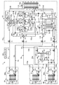
図1に示すように、冷凍装置(1)は、室外に設置される室外ユニット(10)と、室内空間を空調する室内ユニット(20)と、冷蔵倉庫の庫内を冷却する冷蔵ユニット(30)(図では1台のみ表示)と、冷凍倉庫の庫内を冷却する冷凍ユニット(40)(図では1台のみ表示)と、コントローラ(100)とを備えている。冷凍ユニット(40)には、ブースタユニット(45)が接続されている。そして、これらのユニットが接続されて冷媒回路(2)が構成されている。冷媒回路(2)には、大きく分けて、上記室内を空調するための空調系統回路(2a)と、上記冷蔵ユニット(30)及び冷凍ユニット(40)の庫内を冷却するための冷却系統回路(2b)とが形成されている。 As shown in FIG. 1, the refrigeration system (1) comprises an outdoor unit (10) installed outdoors, an indoor unit (20) for air conditioning the indoor space, and a refrigeration unit (30) for cooling the inside of the cold storage warehouse. ) (Only one is shown in the figure), a refrigeration unit (40) (only one is shown in the figure) for cooling the inside of the freezer warehouse, and a controller (100). A booster unit (45) is connected to the refrigeration unit (40). Then, these units are connected to constitute a refrigerant circuit (2). The refrigerant circuit (2) is roughly divided into an air conditioning system circuit (2a) for air conditioning the room, and a cooling system circuit for cooling the inside of the cold storage unit (30) and the freezing unit (40). And (2b) are formed.
室外ユニット(10)には、室外熱交換器(12)を有する熱源側回路としての室外回路(11)が設けられている。室内ユニット(20)には、室内熱交換器(22)を有する室内回路(利用側回路)(21)が設けられている。冷蔵ユニット(30)には、冷蔵熱交換器(32)を有する冷蔵用回路(利用側回路)(31)が設けられている。冷凍ユニット(40)には、冷凍熱交換器(42)を有する冷凍用回路(利用側回路)(41)が設けられている。また、ブースタユニット(45)にはブースタ回路(46)が設けられている。 The outdoor unit (10) is provided with an outdoor circuit (11) as a heat source side circuit having an outdoor heat exchanger (12). The indoor unit (20) is provided with an indoor circuit (use side circuit) (21) having an indoor heat exchanger (22). The refrigeration unit (30) is provided with a refrigeration circuit (use side circuit) (31) having a refrigeration heat exchanger (32). The refrigeration unit (40) is provided with a refrigeration circuit (use side circuit) (41) having a refrigeration heat exchanger (42). The booster unit (45) is provided with a booster circuit (46).
冷凍装置(1)では、室外回路(11)と複数の利用側回路(21,26,31,41)が、第1ガス側連絡配管(51)、第1液側連絡配管(52)、第2ガス側連絡配管(53)、及び第2液側連絡配管(54)からなる4本の連絡配管(51〜54)で互いに接続され、蒸気圧縮式の冷凍サイクルを行う冷媒回路(2)が構成されている。冷蔵用回路(31)と冷凍用回路(41)は並列に接続されている。また、冷凍用回路(41)とブースタ回路(46)は直列に接続されている。 In the refrigeration system (1), the outdoor circuit (11) and the plurality of use side circuits (21, 26, 31, 41) include the first gas side communication pipe (51), the first liquid side communication pipe (52), the first A refrigerant circuit (2) is connected to each other by four connection pipes (51 to 54) consisting of a two gas side connection pipe (53) and a second liquid side connection pipe (54), and performs a vapor compression refrigeration cycle. It is configured. The refrigeration circuit (31) and the refrigeration circuit (41) are connected in parallel. The refrigeration circuit (41) and the booster circuit (46) are connected in series.
第1ガス側連絡配管(51)は、一端が室外回路(11)の第1ガス側閉鎖弁(71)に接続され、他端が室内回路(21)のガス側端に接続されている。第1液側連絡配管(52)は、一端が室外回路(11)の第1液側閉鎖弁(72)に接続され、他端が室内回路(21)の液側端に接続されている。第2ガス側連絡配管(53)は、一端が室外回路(11)の第2ガス側閉鎖弁(73)に接続され、他端が第1分岐ガス管(53a)と第2分岐ガス管(53b)に分岐して冷蔵用回路(31)のガス側端と(ブースタ回路(46)を介して)冷凍用回路(41)のガス側端とに接続されている。第2液側連絡配管(54)は、一端が室外回路(11)の第2液側閉鎖弁(74)に接続され、他端が第1分岐液管(54a)と第2分岐液管(54b)に分岐して冷蔵用回路(31)の液側端と冷凍用回路(41)の液側端に接続されている。
One end of the first gas side connection pipe (51) is connected to the first gas side closing valve (71) of the outdoor circuit (11), and the other end is connected to the gas side end of the indoor circuit (21). One end of the first liquid side communication pipe (52) is connected to the first liquid side closing valve (72) of the outdoor circuit (11), and the other end is connected to the liquid side end of the indoor circuit (21). One end of the second gas side connection pipe (53) is connected to the second gas side closing valve (73) of the outdoor circuit (11), and the other end is connected to the first branch gas pipe (53a) and the second branch gas pipe (
〈室外ユニット〉
室外ユニット(10)は、屋外に設置され、上記室外回路(11)と、該室外回路(11)を収容する室外ケーシング(10a)とを有している。室外回路(11)は、上記室外熱交換器(12)と、圧縮機構(13)と、室外膨張弁(膨張機構)(14)と、レシーバ(15)と、油分離器(16)と、第1,第2及び第3四路切換弁(切り換え機構)(17,18,19)と、上記の4つの閉鎖弁(71,72,73,74)とを備えている。
<Outdoor unit>
The outdoor unit (10) is installed outdoors, and has the outdoor circuit (11) and an outdoor casing (10a) accommodating the outdoor circuit (11). The outdoor circuit (11) includes the outdoor heat exchanger (12), a compression mechanism (13), an outdoor expansion valve (expansion mechanism) (14), a receiver (15), and an oil separator (16). The first, second and third four-way switching valves (switching mechanisms) (17, 18, 19) and the four closing valves (71, 72, 73, 74) described above are provided.
圧縮機構(13)は、第1〜第3圧縮機(13a,13b,13c)を有している。第1〜第3圧縮機(13a,13b,13c)は、いずれも固定スクロール及び可動スクロールが噛み合って圧縮室が形成される全密閉型のスクロール圧縮機である。第1〜第3圧縮機(13a,13b,13c)では、各圧縮室の吸入位置において吸入ポート(図示省略)が開口し、吐出位置において吐出ポート(図示省略)が開口し、中間位置において中間ポート(図示省略)が開口している。 The compression mechanism (13) has first to third compressors (13a, 13b, 13c). The first to third compressors (13a, 13b, 13c) are all hermetic scroll compressors in which a fixed scroll and a movable scroll are engaged to form a compression chamber. In the first to third compressors (13a, 13b, 13c), a suction port (not shown) is opened at the suction position of each compression chamber, a discharge port (not shown) is opened at the discharge position, A port (not shown) is open.
上記第1圧縮機(冷却側圧縮機)(13a)及び第3圧縮機(空調側圧縮機)(13c)は、可変容量型の圧縮機である。つまり、第1圧縮機(13a)及び第3圧縮機(13c)は、インバータ制御によって回転速度が可変に構成されている。一方、第2圧縮機(13b)は、回転速度が一定の固定容量型の圧縮機であり、主に第1圧縮機(13a)の補助に用いられるが、第3圧縮機(13c)の補助に用いることもできる。なお、第2圧縮機(13b)は、可変容量型の圧縮機であってもよい。また、上記第1〜第3圧縮機(13a,13b,13c)には、吸入側に吸入配管(55)が接続される一方、吐出側に吐出配管(56)が接続されている。吐出配管(56)には、異常高圧時に圧縮機(13a,13b,13c)を緊急停止させるための高圧圧力スイッチ(110)が設けられている。 The first compressor (cooling side compressor) (13a) and the third compressor (air conditioning side compressor) (13c) are variable displacement compressors. That is, the rotational speeds of the first compressor (13a) and the third compressor (13c) are configured to be variable by inverter control. On the other hand, the second compressor (13b) is a fixed displacement compressor having a constant rotational speed, and is mainly used for assisting the first compressor (13a), but for assisting the third compressor (13c) It can also be used for The second compressor (13b) may be a variable displacement compressor. Further, a suction pipe (55) is connected to the suction side of the first to third compressors (13a, 13b, 13c), and a discharge pipe (56) is connected to the discharge side. The discharge pipe (56) is provided with a high pressure switch (110) for urgently stopping the compressor (13a, 13b, 13c) under abnormal high pressure.
吸入配管(55)は、流入側が第1流入分岐管(55a)と第2流入分岐管(55b)とに分岐している。第1流入分岐管(55a)は上記第2ガス側閉鎖弁(73)に第3四路切換弁(19)を介して接続される一方、第2流入分岐管(55b)は第2四路切換弁(18)の第2ポート(P2)に接続されている。第1流入分岐管(55a)と第2流入分岐管(55b)は、流入連通管(66)によって互いに接続され、流入連通管(66)には、上記第3圧縮機(空調側圧縮機)(13c)の吸入冷媒量と上記第1圧縮機(冷却側圧縮機)(13a)の吸入冷媒量を調整可能な圧力調整弁(流量調整弁)(67)が設けられている。 The inflow side of the suction pipe (55) branches into a first inflow branch pipe (55a) and a second inflow branch pipe (55b). The first inflow branch pipe (55a) is connected to the second gas side shut-off valve (73) via the third four-way selector valve (19), while the second inflow branch pipe (55b) is connected to the second four path It is connected to the second port (P2) of the switching valve (18). The first inflow branch pipe (55a) and the second inflow branch pipe (55b) are connected to each other by the inflow communication pipe (66), and the third communication compressor (air conditioning side compressor) is connected to the inflow communication pipe (66). A pressure control valve (flow control valve) (67) is provided which can adjust the amount of suction refrigerant of (13c) and the amount of refrigerant suction of the first compressor (cooling side compressor) (13a).
また、吸入配管(55)は、流出側が第1流出分岐管(第1吸入分岐管)(55c)と第2流出分岐管(第2吸入分岐管)(55d)と第3流出分岐管(第3吸入分岐管)(55e)とに分岐している。第1流出分岐管(55c)は上記第1圧縮機(13a)の吸入側端に接続され、第2流出分岐管(55d)は上記第2圧縮機(13b)の吸入側端に接続され、第3流出分岐管(55e)は上記第3圧縮機(13c)の吸入側端に接続されている。 In addition, the suction pipe (55) has a first outflow branch pipe (first suction branch pipe) (55c), a second outflow branch pipe (second suction branch pipe) (55d), and a third outflow branch pipe (third pipe). 3) branch into (intake branch pipe) (55e). The first outflow branch pipe (55c) is connected to the suction side end of the first compressor (13a), and the second outflow branch pipe (55d) is connected to the suction side end of the second compressor (13b), The third outflow branch pipe (55e) is connected to the suction side end of the third compressor (13c).
吐出配管(56)は、流入側が第1流入分岐管(56a)と第2流入分岐管(56b)と第3流入分岐管(56c)とに分岐している。第1流入分岐管(56a)は上記第1圧縮機(13a)の吐出側端に接続され、第2流入分岐管(56b)は上記第2圧縮機(13b)の吐出側端に接続され、第3流入分岐管(56c)は上記第3圧縮機(13c)の吐出側端に接続されている。第1〜第3流入分岐管(56a,56b,56c)には、それぞれに逆止弁(CV1,CV2,CV3)が設けられている。これらの逆止弁(CV1,CV2,CV3)は、第1〜第3圧縮機(13a,13b,13c)から四路切換弁(17,18,19)へ向かう冷媒の流通を許容し、逆方向への冷媒の流通を阻止する。また、吐出配管(56)は、流出側が第1流出分岐管(56d)と第2流出分岐管(56e)と第3流出分岐管(56f)とに分岐している。第1流出分岐管(56d)は第1四路切換弁(17)の第1ポート(P1)に接続され、第2流出分岐管(56e)は第2四路切換弁(18)の第1ポート(P1)に接続され、第3流出分岐管(56f)は第3四路切換弁(19)の第1ポート(P1)に接続されている。 The inflow side of the discharge pipe (56) branches into a first inflow branch pipe (56a), a second inflow branch pipe (56b), and a third inflow branch pipe (56c). The first inflow branch pipe (56a) is connected to the discharge side end of the first compressor (13a), and the second inflow branch pipe (56b) is connected to the discharge side end of the second compressor (13b), The third inflow branch pipe (56c) is connected to the discharge side end of the third compressor (13c). The first to third inflow branch pipes (56a, 56b, 56c) are respectively provided with check valves (CV1, CV2, CV3). These check valves (CV1, CV2, CV3) allow the refrigerant to flow from the first to third compressors (13a, 13b, 13c) to the four-way selector valve (17, 18, 19), and reversely Prevent the flow of refrigerant in the direction. The discharge pipe (56) has an outflow side branched into a first outflow branch pipe (56d), a second outflow branch pipe (56e), and a third outflow branch pipe (56f). The first outflow branch pipe (56d) is connected to the first port (P1) of the first four-way selector valve (17), and the second outflow branch pipe (56e) is connected to the first one of the second four-way selector valve (18). The third outflow branch pipe (56f) is connected to the port (P1), and is connected to the first port (P1) of the third four-way selector valve (19).
油分離器(16)は、吐出配管(56)の中途部に設けられている。油分離器(16)は、第1〜第3圧縮機(13a,13b,13c)から吐出される冷媒に混じった潤滑油を分離し、該潤滑油を第1〜第3圧縮機(13a,13b,13c)に返送する。具体的には、油分離器(16)において冷媒から分離された潤滑油は、油分離器(16)に接続された油戻し配管(50)を介して後述するインジェクション配管(81)の流入端側に返送される。油戻し配管(50)には流量調整弁(48)が設けられている。 The oil separator (16) is provided in the middle of the discharge pipe (56). The oil separator (16) separates the lubricating oil mixed with the refrigerant discharged from the first to third compressors (13a, 13b, 13c), and the lubricating oil is separated from the first to third compressors (13a, 13a, 13c). Return to 13b, 13c). Specifically, the lubricating oil separated from the refrigerant in the oil separator (16) is introduced into the inflow end of an injection pipe (81) described later via an oil return pipe (50) connected to the oil separator (16). It will be returned to the side. The oil return pipe (50) is provided with a flow control valve (48).
第1,第2及び第3四路切換弁(17,18,19)は、第1ポート(P1)が第3ポート(P3)に連通し且つ第2ポート(P2)が第4ポート(P4)に連通する第1状態(図1に実線で示す状態)と、第1ポート(P1)が第4ポート(P4)に連通し且つ第2ポート(P2)が第3ポート(P3)に連通する第2状態(図1に破線で示す状態)とに切り換わる。上記冷凍装置は、この第1,第2及び第3四路切換弁(17,18,19)の切換動作によって、様々な運転を行うことができる。 The first, second and third four-way selector valves (17, 18, 19) communicate the first port (P1) with the third port (P3) and the second port (P2) with the fourth port (P4). And the first port (P1) communicates with the fourth port (P4) and the second port (P2) communicates with the third port (P3). Switching to the second state (indicated by the broken line in FIG. 1). The refrigeration system can perform various operations by the switching operation of the first, second and third four-way selector valves (17, 18, 19).
第1四路切換弁(第1切換弁)(17)の第1ポート(P1)には第1流出分岐管(56d)が接続されている。第1四路切換弁(17)の第2ポート(P2)は、第2四路切換弁(18)の第3ポート(P3)に接続されている。第1四路切換弁(17)の第3ポート(P3)は、冷媒配管を介して第1ガス側閉鎖弁(71)に接続されている。第1四路切換弁(17)の第4ポート(P4)は、室外ガス配管(58)を介して室外熱交換器(12)のガス側端に接続されている。 A first outflow branch pipe (56d) is connected to a first port (P1) of the first four-way selector valve (first selector valve) (17). The second port (P2) of the first four-way selector valve (17) is connected to the third port (P3) of the second four-way selector valve (18). The third port (P3) of the first four-way selector valve (17) is connected to the first gas side shut-off valve (71) via a refrigerant pipe. The fourth port (P4) of the first four-way selector valve (17) is connected to the gas side end of the outdoor heat exchanger (12) via the outdoor gas pipe (58).
第2四路切換弁(第2切換弁)(18)の第1ポート(P1)には第2流出分岐管(56e)が接続されている。第2四路切換弁(18)の第2ポート(P2)は、上述したように第2流入分岐管(55b)に接続されている。第2四路切換弁(18)の第3ポート(P3)は、上述したように第1四路切換弁(17)の第2ポート(P2)に接続されている。第2四路切換弁(18)の第4ポート(P4)は閉鎖された閉鎖ポートになっている。 A second outflow branch pipe (56e) is connected to a first port (P1) of the second four-way selector valve (second selector valve) (18). The second port (P2) of the second four-way selector valve (18) is connected to the second inflow branch pipe (55b) as described above. The third port (P3) of the second four-way selector valve (18) is connected to the second port (P2) of the first four-way selector valve (17) as described above. The fourth port (P4) of the second four-way selector valve (18) is a closed port that is closed.
第3四路切換弁(第3切換弁)(19)の第1ポート(P1)には第3流出分岐管(56f)が接続されている。第3四路切換弁(19)の第2ポート(P2)は、第1流入分岐管(55a)に接続されている。第3四路切換弁(19)の第3ポート(P3)は、開閉弁(64)が設けられた接続配管(65)を介して、レシーバ(15)への冷媒流入管である後述の第2分岐管(79)に接続され、第3四路切換弁(19)の第4ポート(P4)は、冷媒配管を介して第2ガス側閉鎖弁(73)に接続されている。接続配管(65)は、室外熱交換器(12)をバイパスして圧縮機(13a,13b,13c)の吐出側と膨張弁(冷蔵膨張弁(33))の流入側とを繋ぐバイパス流路を構成する。開閉弁(64)は、開度が調節可能な流量調節弁、ないし膨張弁であってもよいし、開閉が切り換えられる電磁開閉弁であってもよい。 A third outflow branch pipe (56f) is connected to the first port (P1) of the third four-way selector valve (third selector valve) (19). The second port (P2) of the third four-way selector valve (19) is connected to the first inflow branch pipe (55a). The third port (P3) of the third four-way selector valve (19) is a refrigerant inflow pipe to the receiver (15) via the connection pipe (65) provided with the on-off valve (64). The second branch pipe (79) is connected, and the fourth port (P4) of the third four-way selector valve (19) is connected to the second gas side shut-off valve (73) via a refrigerant pipe. The connection pipe (65) bypasses the outdoor heat exchanger (12) and connects the discharge side of the compressor (13a, 13b, 13c) and the inflow side of the expansion valve (refrigerated expansion valve (33)) Configure The on-off valve (64) may be a flow control valve whose opening degree can be adjusted, or an expansion valve, or may be a solenoid on-off valve whose opening and closing are switched.
室外熱交換器(12)は、フィン・アンド・チューブ型の熱交換器であり、近傍に室外ファン(12a)が設けられている。この室外熱交換器(12)では、内部を流れる冷媒と室外ファン(12a)が送風する外気との間で熱交換が行われる。室外ファン(12a)は、室外回路(11)と共に室外ケーシング(10a)内に収容されている。 The outdoor heat exchanger (12) is a fin-and-tube type heat exchanger, and an outdoor fan (12a) is provided in the vicinity. In the outdoor heat exchanger (12), heat exchange is performed between the refrigerant flowing inside and the outside air blown by the outdoor fan (12a). The outdoor fan (12a) is accommodated in the outdoor casing (10a) together with the outdoor circuit (11).
室外熱交換器(12)は、詳細は後述する第2暖房冷却運転において、凝縮器となる熱源側熱交換器を構成する。室外ファン(12a)は、熱源側熱交換器である室外熱交換器(12)に対応する熱源側ファンを構成する。 The outdoor heat exchanger (12) constitutes a heat source side heat exchanger to be a condenser in a second heating and cooling operation which will be described in detail later. The outdoor fan (12a) constitutes a heat source side fan corresponding to the outdoor heat exchanger (12) which is a heat source side heat exchanger.
室外熱交換器(12)は、液側端が第1液管(59)を介してレシーバ(15)の頂部に接続されている。レシーバ(15)の底部は、室外熱交換器(12)の底部の凍結防止管(57)と、この凍結防止管(57)に接続された過冷却熱交換器(76)が設けられた第2液管(60)とを介して第2液側閉鎖弁(74)に接続されている。また、第2液管(60)における凍結防止管(57)と過冷却熱交換器(76)との間の部分は、第3液管(62)を介して第1液側閉鎖弁(72)に接続されている。 The outdoor heat exchanger (12) has a liquid side end connected to the top of the receiver (15) via a first liquid pipe (59). The bottom of the receiver (15) is provided with a freeze protection pipe (57) at the bottom of the outdoor heat exchanger (12) and a subcooling heat exchanger (76) connected to the freeze protection pipe (57). It is connected to the second liquid side shut-off valve (74) via the two liquid pipe (60). Further, a portion of the second liquid pipe (60) between the antifreeze pipe (57) and the subcooling heat exchanger (76) is connected to the first liquid side shut-off valve (72) through the third liquid pipe (62). )It is connected to the.
第1液管(59)には室外膨張弁(14)が設けられている。室外膨張弁(14)は、開度が調節可能な電子膨張弁によって構成されている。室外膨張弁(14)は、詳細は後述する第2暖房冷却運転において、凝縮器となる室外熱交換器(12)の流出側に設けられる第1流量調節弁を構成する。 An outdoor expansion valve (14) is provided in the first liquid pipe (59). The outdoor expansion valve (14) is configured by an electronic expansion valve whose opening degree can be adjusted. The outdoor expansion valve (14) constitutes a first flow rate control valve provided on the outflow side of the outdoor heat exchanger (12) serving as a condenser in a second heating / cooling operation described later in detail.
第1液管(59)及び第3液管(62)には、それぞれ逆止弁(CV4,CV5)が設けられている。第1液管(59)の逆止弁(CV4)は、室外熱交換器(12)からレシーバ(15)の頂部へ向かう冷媒の流通を許容し、逆方向への冷媒の流通を阻止する。第3液管(60)の逆止弁(CV5)は、凍結防止管(57)から第1液側閉鎖弁(72)に向かう冷媒の流通を許容し、逆方向への冷媒の流通を阻止する。 The first liquid pipe (59) and the third liquid pipe (62) are provided with check valves (CV4, CV5), respectively. The check valve (CV4) of the first liquid pipe (59) allows the refrigerant to flow from the outdoor heat exchanger (12) to the top of the receiver (15) and prevents the refrigerant from flowing in the reverse direction. The check valve (CV5) of the third liquid pipe (60) allows the refrigerant to flow from the antifreeze pipe (57) toward the first liquid side shut-off valve (72) and prevents the refrigerant from flowing in the reverse direction Do.
第1液管(59)と第2液管(60)との間には、バイパス管(61)が設けられている。バイパス管(61)は、一端が第1液管(59)の逆止弁(CV4)の上流側に接続され、他端が第2液管(60)の逆止弁(CV9)の上流側に接続されている。バイパス管(61)には逆止弁(CV8)が設けられ、室外熱交換器(12)へ向かう冷媒の流れを許容し、逆方向への冷媒の流れを禁止する。バイパス管(61)と第2液側閉鎖弁(74)との間には、バイパス管(61)から第2液側閉鎖弁(74)へ向かう冷媒の流れを許容し、逆方向への冷媒の流れを禁止する逆止弁(CV9)が設けられている。 A bypass pipe (61) is provided between the first liquid pipe (59) and the second liquid pipe (60). One end of the bypass pipe (61) is connected to the upstream side of the check valve (CV4) in the first liquid pipe (59), and the other end is upstream of the check valve (CV9) in the second liquid pipe (60). It is connected to the. The bypass pipe (61) is provided with a check valve (CV8) to allow the flow of the refrigerant toward the outdoor heat exchanger (12) and to prohibit the flow of the refrigerant in the reverse direction. Between the bypass pipe (61) and the second liquid side shut-off valve (74), allow the flow of the refrigerant from the bypass pipe (61) to the second liquid side shut-off valve (74). A check valve (CV9) for inhibiting the flow of
過冷却熱交換器(76)は、高圧側流路(76a)と低圧側流路(76b)とを備えている。過冷却熱交換器(76)は、高圧側流路(76a)及び低圧側流路(76b)を流れる冷媒同士が熱交換して高圧側流路(76a)の冷媒が過冷却されるように構成されている。低圧側流路(76b)は、第2液管(60)の逆止弁(CV9)の上流側と後述するインジェクション配管(81)の流入端とを接続する第1分岐管(77)の一部を構成している。第1分岐管(77)の低圧側流路(76b)の上流側には過冷却用膨張弁(78)が設けられている。過冷却用膨張弁(78)は、開度が調節可能な電子膨張弁で構成されている。 The subcooling heat exchanger (76) includes a high pressure side flow passage (76a) and a low pressure side flow passage (76b). In the subcooling heat exchanger (76), the refrigerant flowing in the high pressure side flow passage (76a) and the low pressure side flow passage (76b) exchanges heat so that the refrigerant in the high pressure side flow passage (76a) is supercooled. It is configured. The low pressure side flow passage (76b) is one of first branch pipes (77) for connecting the upstream side of the check valve (CV9) of the second liquid pipe (60) and the inflow end of the injection pipe (81) described later. Make up the department. An overcooling expansion valve (78) is provided on the upstream side of the low pressure side flow passage (76b) of the first branch pipe (77). The subcooling expansion valve (78) is composed of an electronic expansion valve whose opening degree can be adjusted.
第3液管(62)の逆止弁(CV5)の下流側と第1液管(59)の逆止弁(CV4)の下流側との間には、第2分岐管(79)が設けられている。第2分岐管(79)には、逆止弁(CV6)が設けられている。逆止弁(CV6)は、第2液管(60)から第1液管(59)へ向かう冷媒の流通を許容し、逆方向への冷媒の流通を阻止する。 A second branch pipe (79) is provided between the downstream side of the check valve (CV5) of the third liquid pipe (62) and the downstream side of the check valve (CV4) of the first liquid pipe (59) It is done. The second branch pipe (79) is provided with a check valve (CV6). The check valve (CV6) allows the flow of the refrigerant from the second liquid pipe (60) to the first liquid pipe (59), and prevents the flow of the refrigerant in the reverse direction.
室外回路(11)には、逆サイクルデフロスト運転時の冷媒戻り配管(80)が設けられている。冷媒戻り配管(80)は、一端が第2液側閉鎖弁(74)とバイパス管(61)との間に接続され、他端が第2分岐管(79)に第1液管(59)と接続配管(65)との間で接続されている。冷媒戻り配管(80)には、レシーバ(15)へ向かう冷媒の流れを許容し、逆方向への冷媒の流れを禁止する逆止弁(CV10)が設けられている。 The outdoor circuit (11) is provided with a refrigerant return pipe (80) during reverse cycle defrost operation. One end of the refrigerant return pipe (80) is connected between the second liquid side closing valve (74) and the bypass pipe (61), and the other end is connected to the second branch pipe (79) as the first liquid pipe (59) And connection piping (65) are connected. The refrigerant return pipe (80) is provided with a check valve (CV10) which allows the flow of the refrigerant toward the receiver (15) and prohibits the flow of the refrigerant in the reverse direction.
インジェクション配管(81)は、上述のように流入端が上記第1分岐管(77)に接続され、流出端は3つに分岐している。具体的には、インジェクション配管(81)の流出端は、第1〜第3インジェクション管(81a,81b,81c)に分岐している。各インジェクション管(81a,81b,81c)は、各圧縮機(13a,13b,13c)の中間圧の圧縮室に連通する中間圧ポートに接続されている。第1インジェクション管(81a)には第1膨張弁(82a)が、第2インジェクション管(81b)には第2膨張弁(82b)が、第3インジェクション管(81c)には第3膨張弁(82c)がそれぞれ接続される。各膨張弁(82a,82b,82c)は、開度可変の電子膨張弁によって構成されている。各インジェクション管(81a,81b,81c)は、過冷却熱交換器(76)から各圧縮機(13a,13b,13c)の中間圧の圧縮室へガス冷媒を導入するインジェクション回路を構成している。 As described above, the inflow end of the injection pipe (81) is connected to the first branch pipe (77), and the outflow end is branched into three. Specifically, the outflow end of the injection pipe (81) is branched into first to third injection pipes (81a, 81b, 81c). Each injection pipe (81a, 81b, 81c) is connected to an intermediate pressure port communicating with a compression chamber at an intermediate pressure of each compressor (13a, 13b, 13c). The first expansion valve (82a) is for the first injection pipe (81a), the second expansion valve (82b) for the second injection pipe (81b), and the third expansion valve (for the third injection pipe (81c). 82c) are connected respectively. Each expansion valve (82a, 82b, 82c) is comprised by the electronic expansion valve of opening degree variable. Each injection pipe (81a, 81b, 81c) constitutes an injection circuit for introducing the gas refrigerant from the subcooling heat exchanger (76) into the compression chamber at an intermediate pressure of each compressor (13a, 13b, 13c) .
室外回路(11)には、各種センサが設けられている。例えば、吐出配管(56)には、各圧縮機(13a,13b,13c)の吐出冷媒の温度をそれぞれ検出する吐出温度センサ(111a, 111b, 111c)と、各圧縮機(13a,13b,13c)の吐出冷媒の圧力を検出する吐出圧力センサ(112)とが設けられている。これらの吐出温度センサ(111a,111b, 111c)は、第1圧縮機(13a)に対応する第1吐出温度センサ(111a)と、第2圧縮機(13b)に対応する第2吐出温度センサ(111b)と、第3圧縮機(13c)に対応する第3吐出温度センサ(111c)とで構成される。また、吸入配管(55)には、各圧縮機(13a,13b,13c)の吸入冷媒の温度を検出する吸入温度センサ(113)と、各圧縮機(13a,13b,13c)の吸入冷媒の圧力を検出する吸入圧力センサ(114)が設けられている。 Various sensors are provided in the outdoor circuit (11). For example, the discharge piping (56) includes discharge temperature sensors (111a, 111b, 111c) for detecting the temperatures of the refrigerant discharged from the compressors (13a, 13b, 13c), and the compressors (13a, 13b, 13c). And a discharge pressure sensor (112) for detecting the pressure of the discharge refrigerant. The discharge temperature sensors (111a, 111b, 111c) correspond to the first discharge temperature sensor (111a) corresponding to the first compressor (13a) and the second discharge temperature sensor (111) corresponding to the second compressor (13b). And 111b) and a third discharge temperature sensor (111c) corresponding to the third compressor (13c). In the suction pipe (55), a suction temperature sensor (113) for detecting the temperature of the suction refrigerant of each compressor (13a, 13b, 13c) and the suction refrigerant of each compressor (13a, 13b, 13c) A suction pressure sensor (114) is provided to detect pressure.
室外熱交換器(12)の近傍には、室外の外気温度を検出する室外温度センサ(115)が設けられている。室外熱交換器(12)の液側端部には、第1温度センサ(118)が設けられている。過冷却熱交換器(76)の低圧側流路(76b)の下流側には、圧力センサ(117)が設けられている。また、第2液管(60)には、レシーバ(15)の圧力を検出する圧力センサ(119)が設けられている。これらのセンサの検出値は、後述するコントローラ(100)に入力される。 In the vicinity of the outdoor heat exchanger (12), an outdoor temperature sensor (115) for detecting the outdoor air temperature outside the room is provided. A first temperature sensor (118) is provided at the liquid side end of the outdoor heat exchanger (12). A pressure sensor (117) is provided downstream of the low pressure side flow passage (76b) of the subcooling heat exchanger (76). Further, the second liquid pipe (60) is provided with a pressure sensor (119) for detecting the pressure of the receiver (15). The detection values of these sensors are input to a controller (100) described later.
詳細は後述する第2暖房冷却運転では、吐出圧力センサ(112)及び第1温度センサ(118)の検出値に基づいて室外熱交換器(12)を流出する液冷媒の過冷却度(SC1)が求められる。つまり、吐出圧力センサ(112)で検出される冷媒の吐出圧力(Pd)は、室外熱交換器(12)を流れる冷媒の圧力に相当する。従って、この吐出圧力(Pd)に対応する飽和温度が、室外熱交換器(12)の凝縮温度(Te1)となる。従って、この凝縮温度(Te1)から、第1温度センサ(118)で検出した冷媒の温度(T1)を差し引くことで、室外熱交換器(12)を流出する冷媒の過冷却度(SC1)(SC1=Te1−T1)を求めることができる。 In the second heating / cooling operation, the details of which will be described later, the degree of supercooling (SC1) of the liquid refrigerant flowing out of the outdoor heat exchanger (12) based on the detected values of the discharge pressure sensor (112) and the first temperature sensor (118). Is required. That is, the discharge pressure (Pd) of the refrigerant detected by the discharge pressure sensor (112) corresponds to the pressure of the refrigerant flowing through the outdoor heat exchanger (12). Therefore, the saturation temperature corresponding to the discharge pressure (Pd) is the condensation temperature (Te1) of the outdoor heat exchanger (12). Therefore, by subtracting the temperature (T1) of the refrigerant detected by the first temperature sensor (118) from the condensation temperature (Te1), the degree of subcooling (SC1) of the refrigerant flowing out of the outdoor heat exchanger (12) (SC1) SC1 = Te1-T1) can be obtained.
〈室内ユニット〉
室内ユニット(20)は、室内に設置され、室内回路(21)と、室内回路(21)を収容する室内ケーシング(20a)とを有している。室内回路(21)は、ガス側端が第1ガス側連絡配管(51)に接続され、液側端が第1液側連絡配管(52)に接続されている。室内回路(21)には、ガス側端から順に、室内熱交換器(22)及び室内膨張弁(膨張機構)(23)が設けられている。室内熱交換器(22)は、クロスフィン式のフィン・アンド・チューブ型熱交換器によって構成され、近傍に室内ファン(22a)が設けられている。室内ファン(22a)は、室内回路(21)と共に室内ケーシング(20a)内に収容されている。室内熱交換器(22)では、内部を流れる冷媒と室内ファン(22a)が送風する室内空気との間で熱交換が行われる。
<Indoor unit>
The indoor unit (20) is installed indoors and has an indoor circuit (21) and an indoor casing (20a) that accommodates the indoor circuit (21). The indoor circuit (21) has a gas side end connected to the first gas side communication pipe (51) and a liquid side end connected to the first liquid side communication pipe (52). The indoor heat exchanger (22) and the indoor expansion valve (expansion mechanism) (23) are provided in the indoor circuit (21) in order from the gas side end. The indoor heat exchanger (22) is constituted by a cross fin type fin-and-tube heat exchanger, and an indoor fan (22a) is provided in the vicinity. The indoor fan (22a) is housed in the indoor casing (20a) together with the indoor circuit (21). In the indoor heat exchanger (22), heat exchange is performed between the refrigerant flowing inside and the indoor air blown by the indoor fan (22a).
室内膨張弁(23)は、開度が調節可能な電子膨張弁によって構成されている。室内熱交換器(22)の近傍には、室内空気の温度を検出する室内温度センサ(121)が設けられている。室内回路(21)では、室内熱交換器(22)の伝熱管に、第2温度センサ(122)が設けられている。また、室内回路(21)におけるガス側端の近傍に、蒸発温度センサ(123)が設けられている。 The indoor expansion valve (23) is constituted by an electronic expansion valve whose opening degree can be adjusted. In the vicinity of the indoor heat exchanger (22), an indoor temperature sensor (121) for detecting the temperature of the indoor air is provided. In the indoor circuit (21), a heat transfer pipe of the indoor heat exchanger (22) is provided with a second temperature sensor (122). Further, an evaporation temperature sensor (123) is provided in the vicinity of the gas side end of the indoor circuit (21).
室内熱交換器(22)は、詳細は後述する第2暖房冷却運転において、凝縮器としての第1利用側熱交換器を構成する。 The indoor heat exchanger (22) constitutes a first usage-side heat exchanger as a condenser in a second heating / cooling operation which will be described in detail later.
詳細は後述する第2暖房冷却運転では、吐出圧力センサ(112)及び第2温度センサ(122)の検出値に基づいて室外熱交換器(12)を流出する液冷媒の過冷却度(SC2)が求められる。つまり、吐出圧力センサ(112)で検出される冷媒の吐出圧力(Pd)は、室内熱交換器(22)を流れる冷媒の圧力に相当する。従って、この吐出圧力(Pd)に対応する飽和温度が、室内熱交換器(22)の凝縮温度(Te2)(Te2≒Te1)となる。従って、この凝縮温度(Te2)から、第2温度センサ(122)で検出した冷媒の温度(T2)を差し引くことで、室外熱交換器(12)を流出する冷媒の過冷却度(SC2)(SC2=Te2−T2)を求めることができる。 In the second heating / cooling operation, the details of which will be described later, the degree of supercooling (SC2) of the liquid refrigerant flowing out of the outdoor heat exchanger (12) based on the detection values of the discharge pressure sensor (112) and the second temperature sensor (122). Is required. That is, the discharge pressure (Pd) of the refrigerant detected by the discharge pressure sensor (112) corresponds to the pressure of the refrigerant flowing through the indoor heat exchanger (22). Therefore, the saturation temperature corresponding to the discharge pressure (Pd) is the condensation temperature (Te2) (Te2 ≒ Te1) of the indoor heat exchanger (22). Therefore, by subtracting the temperature (T2) of the refrigerant detected by the second temperature sensor (122) from the condensation temperature (Te2), the degree of supercooling of the refrigerant flowing out of the outdoor heat exchanger (12) (SC2) SC2 = Te2-T2) can be obtained.
〈冷蔵ユニット〉
冷蔵ユニット(30)は、上記冷蔵用回路(31)と、該冷蔵用回路(31)を収容する冷蔵庫(30a)とを有している。
<Colder unit>
The refrigeration unit (30) has the refrigeration circuit (31) and a refrigerator (30a) for accommodating the refrigeration circuit (31).
冷蔵ユニット(30)の冷蔵用回路(31)は、ガス側端が第2ガス側連絡配管(53)の第1分岐ガス管(53a)に接続され、液側端が第2液側連絡配管(54)の第1分岐液管(54a)に接続されている。冷蔵用回路(31)には、ガス側端から順に、冷蔵熱交換器(32)及び冷蔵膨張弁(膨張機構)(33)が設けられている。冷蔵熱交換器(32)は、クロスフィン式のフィン・アンド・チューブ型熱交換器によって構成され、近傍に庫内ファン(32a)が設けられている。庫内ファン(32a)は、冷蔵用回路(31)と共に冷蔵庫(30a)内に収容されている。冷蔵熱交換器(32)では、内部を流れる冷媒と庫内ファン(32a)が送風する冷蔵庫(30a)内の庫内空気との間で熱交換が行われる。冷蔵膨張弁(33)は、開度が調節可能な電子膨張弁により構成されている。また、冷蔵熱交換器(32)の近傍には、庫内空気の温度を検出する庫内温度センサ(131)が設けられている。また、冷蔵熱交換器(32)の伝熱管に、蒸発温度センサ(132)が設けられている。また、冷蔵用回路(31)におけるガス側端の近傍に、ガス温度センサ(133)が設けられている。 In the refrigeration circuit (31) of the refrigeration unit (30), the gas side end is connected to the first branch gas pipe (53a) of the second gas side communication pipe (53), and the liquid side end is the second liquid side communication pipe It is connected to the first branched liquid pipe (54a) of (54). The refrigeration circuit (31) is provided with a refrigeration heat exchanger (32) and a refrigeration expansion valve (expansion mechanism) (33) in this order from the gas side end. The cold storage heat exchanger (32) is constituted by a cross fin type fin-and-tube heat exchanger, and an internal fan (32a) is provided in the vicinity. The internal fan (32a) is housed in the refrigerator (30a) together with the circuit for refrigeration (31). In the refrigeration heat exchanger (32), heat exchange is performed between the refrigerant flowing inside and the air inside the refrigerator (30a) which the inside fan (32a) blows. The cold storage expansion valve (33) is constituted by an electronic expansion valve whose opening degree can be adjusted. Further, an in-compartment temperature sensor (131) for detecting the temperature of the in-compartment air is provided in the vicinity of the cold storage heat exchanger (32). Moreover, the evaporation temperature sensor (132) is provided in the heat transfer tube of the refrigeration heat exchanger (32). In addition, a gas temperature sensor (133) is provided in the vicinity of the gas side end of the refrigeration circuit (31).
冷蔵熱交換器(32)は、詳細は後述する第2暖房冷却運転において、蒸発器となる第2利用側熱交換器を構成する。 The refrigeration heat exchanger (32) constitutes a second usage-side heat exchanger as an evaporator in a second heating and cooling operation which will be described in detail later.
〈冷凍ユニット〉
冷凍ユニット(40)は、上記冷凍用回路(41)と、該冷凍用回路(41)を収容する冷凍庫(40a)とを有している。
<Freezing unit>
The refrigeration unit (40) includes the refrigeration circuit (41) and a freezer (40a) that accommodates the refrigeration circuit (41).
冷凍ユニット(40)の冷凍用回路(41)は、ガス側端が後述するブースタユニット(45)を介して第2ガス側連絡配管(53)の第1分岐ガス管(53a)に接続され、液側端が第2液側連絡配管(54)の第1分岐液管(54a)に接続されている。冷凍用回路(41)には、ガス側端から順に、冷凍熱交換器(42)及び冷凍膨張弁(膨張機構)(43)が設けられている。冷凍熱交換器(42)は、クロスフィン式のフィン・アンド・チューブ型熱交換器によって構成され、近傍に庫内ファン(42a)が設けられている。庫内ファン(42a)は、冷凍用回路(41)と共に冷凍庫(40a)内に収容されている。冷凍熱交換器(42)では、内部を流れる冷媒と庫内ファン(42a)が送風する冷凍庫(40a)内の庫内空気との間で熱交換が行われる。冷凍膨張弁(43)は、開度が調節可能な電子膨張弁により構成されている。冷凍熱交換器(42)の近傍には、庫内空気の温度を検出する庫内温度センサ(141)が設けられている。また、冷凍熱交換器(42)の伝熱管に、蒸発温度センサ(142)が設けられている。冷凍用回路(41)におけるガス側端の近傍に、ガス温度センサ(143)が設けられている。 The refrigeration circuit (41) of the refrigeration unit (40) is connected at the gas side end to the first branch gas pipe (53a) of the second gas side connection pipe (53) via a booster unit (45) described later, The liquid side end is connected to the first branched liquid pipe (54a) of the second liquid side communication pipe (54). The refrigeration circuit (41) is provided with a refrigeration heat exchanger (42) and a refrigeration expansion valve (expansion mechanism) (43) in this order from the gas side end. The refrigeration heat exchanger (42) is constituted by a cross fin type fin-and-tube heat exchanger, and an internal fan (42a) is provided in the vicinity. The internal fan (42a) is accommodated in the freezer (40a) together with the circuit for refrigeration (41). In the refrigeration heat exchanger (42), heat exchange is performed between the refrigerant flowing inside and the air inside the freezer (40a) which the inside fan (42a) blows. The refrigeration expansion valve (43) is constituted by an electronic expansion valve whose opening degree can be adjusted. An in-compartment temperature sensor (141) for detecting the temperature of the in-compartment air is provided in the vicinity of the refrigeration heat exchanger (42). Further, an evaporation temperature sensor (142) is provided in the heat transfer pipe of the refrigeration heat exchanger (42). A gas temperature sensor (143) is provided near the gas side end of the refrigeration circuit (41).
冷凍熱交換器(42)は、詳細は後述する第2暖房冷却運転において、蒸発器となる第2利用側熱交換器を構成する。 The refrigeration heat exchanger (42) constitutes a second usage-side heat exchanger as an evaporator in a second heating and cooling operation which will be described in detail later.
〈ブースタユニット〉
ブースタ回路(46)には、運転容量が可変のブースタ圧縮機(47)が設けられている。ブースタ圧縮機(47)の吐出管(91)には、ブースタ圧縮機(47)側から順に、油分離器(92)、高圧圧力スイッチ(93)、逆止弁(CV11)が設けられている。油分離器(92)には、キャピラリーチューブ(95)が設けられた油戻し管(96)が接続されている。また、ブースタ回路(46)には、ブースタ圧縮機(47)をバイパスするバイパス管(97)が設けられている。バイパス管(97)には、逆止弁(CV12)が設けられている。
<Booster unit>
The booster circuit (46) is provided with a booster compressor (47) whose operating capacity is variable. The discharge pipe (91) of the booster compressor (47) is provided with an oil separator (92), a high pressure switch (93) and a check valve (CV11) in this order from the booster compressor (47) side . An oil return pipe (96) provided with a capillary tube (95) is connected to the oil separator (92). The booster circuit (46) is also provided with a bypass pipe (97) for bypassing the booster compressor (47). The bypass pipe (97) is provided with a check valve (CV12).
第2分岐ガス管(53b)と第2分岐液管(54b)は、ブースタユニット(45)内で接続管(98)により接続される。接続管(98)には調整弁(99)が設けられている。 The second branch gas pipe (53b) and the second branch liquid pipe (54b) are connected by the connection pipe (98) in the booster unit (45). The connecting pipe (98) is provided with a control valve (99).
〈コントローラ〉
コントローラ(100)(制御部)は、マイクロコンピュータと、該マイクロコンピュータを動作させるためのソフトウエアを格納するメモリディバイス(具体的には半導体メモリ)とを用いて構成されている。コントローラ(100)は、冷凍装置(1)の各機器を制御する。
<controller>
The controller (100) (control unit) is configured using a microcomputer and a memory device (specifically, a semiconductor memory) that stores software for operating the microcomputer. The controller (100) controls each device of the refrigeration system (1).
コントローラ(100)による各機器の制御により、冷凍装置(1)の各運転が切り換えられる。冷凍装置(1)は、室内ユニット(20)で室内を冷房する冷房運転と、室内ユニット(20)で室内を暖房する暖房運転とを行う。 Each operation of the refrigeration system (1) is switched by control of each device by the controller (100). The refrigeration system (1) performs a cooling operation to cool the room with the indoor unit (20) and a heating operation to heat the room with the indoor unit (20).
冷房運転では、室内ユニット(20)で室内空気を冷却すると同時に冷蔵ユニット(30)及び冷凍ユニット(40)で庫内空気を冷却する冷房冷却運転を含む。暖房運転は、第1暖房冷却運転、第2暖房冷却運転、及び第3暖房冷却運転を含む。第1暖房冷却運転では、室外熱交換器(12)が実質的に停止状態となると同時に冷蔵ユニット(30)及び冷凍ユニット(40)で庫内空気を冷却する。第2暖房冷却運転では、室外熱交換器(12)が凝縮器になると同時に冷蔵ユニット(30)及び冷凍ユニット(40)で庫内空気を冷却する。第3暖房冷却運転では、室外熱交換器(12)が蒸発器になると同時に冷蔵ユニット(30)及び冷凍ユニット(40)で庫内空気を冷却する。 In the cooling operation, the cooling operation includes cooling the room air by the indoor unit (20) and simultaneously cooling the air in the cold storage unit (30) and the freezing unit (40). The heating operation includes a first heating / cooling operation, a second heating / cooling operation, and a third heating / cooling operation. In the first heating / cooling operation, the indoor heat is cooled by the refrigeration unit (30) and the refrigeration unit (40) at the same time when the outdoor heat exchanger (12) is substantially stopped. In the second heating / cooling operation, the outdoor heat exchanger (12) becomes a condenser and at the same time cools the internal air by the refrigeration unit (30) and the refrigeration unit (40). In the third heating and cooling operation, the outdoor heat exchanger (12) becomes an evaporator and simultaneously cools the internal air by the refrigeration unit (30) and the refrigeration unit (40).
また、冷房運転及び暖房運転では、冷蔵ユニット(30)の冷蔵熱交換器(32)を除霜するデフロスト運転がそれぞれ実行される。 Further, in the cooling operation and the heating operation, the defrosting operation for defrosting the refrigeration heat exchanger (32) of the refrigeration unit (30) is executed respectively.
コントローラ(100)は、第2暖房冷却運転において、室外熱交換器(12)及び室内熱交換器(22)に溜まった液冷媒の量を示す指標に基づいて、室外膨張弁(14)の開度を調節する制御を行う。本実施形態のコントローラ(100)は、上記液冷媒の指標として、室外熱交換器(12)及び室内熱交換器(22)を流出する冷媒の過冷却度(SC1,SC2)をそれぞれ用いる。 The controller (100) opens the outdoor expansion valve (14) based on the index indicating the amount of liquid refrigerant accumulated in the outdoor heat exchanger (12) and the indoor heat exchanger (22) in the second heating / cooling operation. Control to adjust the degree. The controller (100) of the present embodiment uses the subcooling degree (SC1, SC2) of the refrigerant flowing out of the outdoor heat exchanger (12) and the indoor heat exchanger (22) as an index of the liquid refrigerant.
図8に示すように、コントローラ(100)は、入力部(101)、演算部(102)、判定部(103)、及び出力部(104)を有している。 As shown in FIG. 8, the controller (100) includes an input unit (101), an arithmetic unit (102), a determination unit (103), and an output unit (104).
入力部(101)には、各センサの検出値や各機器の状態を示す信号が入力される。より詳細には、本実施形態の入力部(101)には、第2暖房冷却運転において、吐出圧力センサ(112)で検出した冷媒の吐出圧力(Pd)と、第1温度センサ(118)で検出した冷媒の温度(T1)(室外熱交換器(12)を流出する冷媒の温度)と、第2温度センサ(122)で検出した冷媒の温度(T2)(室内熱交換器(22)を流出する冷媒の温度)とが入力される。 A signal indicating the detection value of each sensor or the state of each device is input to the input unit (101). More specifically, in the input portion (101) of the present embodiment, the discharge pressure (Pd) of the refrigerant detected by the discharge pressure sensor (112) in the second heating and cooling operation and the first temperature sensor (118) The detected refrigerant temperature (T1) (the temperature of the refrigerant flowing out of the outdoor heat exchanger (12)) and the temperature of the refrigerant detected by the second temperature sensor (122) (T2) (the indoor heat exchanger (22) The temperature of the refrigerant flowing out is input.
演算部(102)は、入力部(101)に入力された検出値に基づいて、室外熱交換器(12)に対応する過冷却度((SC1)、第1過冷却度ともいう)と、室内熱交換器(22)に対応する過冷却度((SC2)、第2過冷却度ともいう)とを算出する。ここで、第1過冷却度(SC1)は、吐出圧力(Pd)に対応する飽和温度(室外熱交換器(12)の冷媒の凝縮温度(Te1))から室外熱交換器(12)を流出する冷媒の温度(T1)を差し引くことで得られる。また、第2過冷却度(SC2)は、吐出圧力(Pd)に対応する飽和温度(室内熱交換器(22)の冷媒の凝縮温度(Te2))から室内熱交換器(22)を流出する冷媒の温度(T2)を差し引くことで得られる。 The calculation unit (102) determines, based on the detected value input to the input unit (101), a degree of subcooling ((SC1), also referred to as a first degree of subcooling) corresponding to the outdoor heat exchanger (12); The degree of subcooling (also referred to as (SC2), second degree of subcooling) corresponding to the indoor heat exchanger (22) is calculated. Here, the first degree of subcooling (SC1) flows the outdoor heat exchanger (12) from the saturation temperature (the condensation temperature (Te1) of the refrigerant of the outdoor heat exchanger (12)) corresponding to the discharge pressure (Pd) Obtained by subtracting the temperature (T1) of the refrigerant to be used. In addition, the second degree of subcooling (SC2) flows out of the indoor heat exchanger (22) from the saturation temperature (condensing temperature (Te2) of the refrigerant of the indoor heat exchanger (22)) corresponding to the discharge pressure (Pd) It is obtained by subtracting the temperature (T2) of the refrigerant.
判定部(103)は、演算部(102)で求めた第1過冷却度(SC1)及び第2過冷却度(SC2)に基づき、室外膨張弁(14)及び室内膨張弁(23)の開度を調節するための判定を行う。この判定では、第1過冷却度(SC1)及び第2過冷却度(SC2)の大小を比較する(詳細は後述する)。 The determination unit (103) opens the outdoor expansion valve (14) and the indoor expansion valve (23) based on the first degree of subcooling (SC1) and the second degree of subcooling (SC2) obtained by the calculation unit (102). Make a decision to adjust the degree. In this determination, the magnitudes of the first degree of subcooling (SC1) and the second degree of subcooling (SC2) are compared (the details will be described later).
出力部(104)は、判定部(103)の判定結果に基づいて、室外膨張弁(14)の開度を制御するための信号を出力する。 The output unit (104) outputs a signal for controlling the opening degree of the outdoor expansion valve (14) based on the determination result of the determination unit (103).
−運転動作−
冷凍装置(1)では、冷房冷却運転、第1暖房冷却運転、第2暖房冷却運転、第3暖房冷却運転の各運転モードが、各四路切換弁(17,18,19)を切り換えることにより実行される。
-Driving operation-
In the refrigeration system (1), each operation mode of the cooling / cooling operation, the first heating / cooling operation, the second heating / cooling operation, and the third heating / cooling operation is switched by switching the four-way switching valves (17, 18, 19). To be executed.
〈冷房冷却運転〉
図2に示す冷房冷却運転は、室内ユニット(20)の冷房と冷蔵ユニット(30)及び冷凍ユニット(40)の冷却を行う運転である。コントローラ(100)は、第1,第2四路切換弁(17,18)を第2状態に切り換え、第3四路切換弁(19)を第1状態に切り換え、室外膨張弁(14)を全開状態に制御し、冷蔵膨張弁(33)、冷凍膨張弁(43)及び室内膨張弁(23)の開度を適宜調節する。また、開閉弁(64)と圧力調整弁(67)は全閉に制御される。
<Cooling cooling operation>
The cooling operation shown in FIG. 2 is an operation for cooling the indoor unit (20) and cooling the refrigeration unit (30) and the refrigeration unit (40). The controller (100) switches the first and second four-way selector valves (17, 18) to the second state, switches the third four-way selector valve (19) to the first state, and the outdoor expansion valve (14). It controls to a fully open state, and adjusts the opening degree of a refrigeration expansion valve (33), a freezing expansion valve (43), and an indoor expansion valve (23) suitably. Further, the on-off valve (64) and the pressure control valve (67) are controlled to be fully closed.
冷媒回路(2)では以下のように冷媒が循環する。 In the refrigerant circuit (2), the refrigerant circulates as follows.
第1〜第3圧縮機(13a,13b,13c)で圧縮された冷媒は、吐出配管(56)において合流してから油分離器(16)において潤滑油が分離され、第1四路切換弁(17)及び室外ガス配管(58)を通過して室外熱交換器(12)に流入する。室外熱交換器(12)では、冷媒が室外空気に放熱して凝縮する。室外熱交換器(12)で凝縮した液冷媒は、第1液管(59)を介してレシーバ(15)に流入し、該レシーバ(15)に貯留される。 The refrigerant compressed by the first to third compressors (13a, 13b, 13c) merges in the discharge pipe (56) and then the lubricating oil is separated in the oil separator (16), and the first four-way switching valve (17) and the outdoor gas pipe (58) to flow into the outdoor heat exchanger (12). In the outdoor heat exchanger (12), the refrigerant releases heat to the outdoor air and condenses. The liquid refrigerant condensed in the outdoor heat exchanger (12) flows into the receiver (15) through the first liquid pipe (59) and is stored in the receiver (15).
レシーバ(15)に貯留された液冷媒は、レシーバ(15)から流出して凍結防止管(57)を通過し、第2液管(60)を第1液側閉鎖弁(72)及び第2液側閉鎖弁(74)に向かって分流する。その際に、液冷媒は過冷却熱交換器(76)を通過する。 The liquid refrigerant stored in the receiver (15) flows out of the receiver (15) and passes through the antifreeze pipe (57), and the second liquid pipe (60) is subjected to the first liquid side shut-off valve (72) and the second It diverts towards the liquid side shutoff valve (74). At that time, the liquid refrigerant passes through the subcooling heat exchanger (76).
高圧の液冷媒は、過冷却熱交換器(76)の高圧側流路(76a)に流入する。一方、過冷却熱交換器(76)の低圧側流路(76b)には高圧側流路(76a)を通過後に第2液管(60)から第1分岐管(77)に分岐して過冷却用膨張弁(78)で減圧された冷媒が流入する。低圧側流路(76b)を流れる冷媒は、高圧側流路(76a)を流れる高圧の液冷媒と熱交換して蒸発する一方、高圧側流路(76a)の高圧の液冷媒は、低圧側流路(76b)の冷媒に放熱することによって過冷却状態となる。第2液側閉鎖弁(74)を通過した冷媒は、第2液側連絡配管(54)に流入する。第1液側閉鎖弁(72)を通過した冷媒は、第1液側連絡配管(52)に流入する。蒸発した低圧側流路(76b)の冷媒は、インジェクション配管(81)に流入する。 The high pressure liquid refrigerant flows into the high pressure side flow passage (76a) of the subcooling heat exchanger (76). On the other hand, after passing through the high pressure side channel (76a), the low pressure side channel (76b) of the subcooling heat exchanger (76) branches from the second liquid pipe (60) to the first branch pipe (77) and The refrigerant whose pressure is reduced by the cooling expansion valve (78) flows in. The refrigerant flowing in the low pressure side flow passage (76b) exchanges heat with the high pressure liquid refrigerant flowing in the high pressure side flow passage (76a) and evaporates, while the high pressure liquid refrigerant in the high pressure side flow passage (76a) is evaporated on the low pressure side The heat is released to the refrigerant of the flow path (76 b) to be a supercooled state. The refrigerant that has passed through the second liquid side shut-off valve (74) flows into the second liquid side communication pipe (54). The refrigerant that has passed through the first liquid side shut-off valve (72) flows into the first liquid side communication pipe (52). The evaporated refrigerant in the low pressure side channel (76b) flows into the injection pipe (81).
第2液側連絡配管(54)に流入した液冷媒は、2つに分流して第1分岐液管(54a)及び第2分岐液管(54b)のそれぞれに流入する。第1分岐液管(54a)に流入した液冷媒は、冷蔵ユニット(30)の冷蔵用回路(31)に流入する一方、第2分岐液管(54b)に流入した液冷媒は、冷凍ユニット(40)の冷凍用回路(41)に流入する。冷蔵用回路(31)及び冷凍用回路(41)に流入した液冷媒は、冷蔵膨張弁(33)及び冷凍膨張弁(43)で減圧された後、冷蔵熱交換器(32)及び冷凍熱交換器(42)に流入する。冷蔵熱交換器(32)及び冷凍熱交換器(42)では、冷媒が庫内空気から吸熱して蒸発する。その結果、庫内空気が冷却される。 The liquid refrigerant flowing into the second liquid side communication pipe (54) is branched into two and flows into each of the first branched liquid pipe (54a) and the second branched liquid pipe (54b). The liquid refrigerant flowing into the first branched liquid pipe (54a) flows into the refrigeration circuit (31) of the refrigerating unit (30), while the liquid refrigerant flowing into the second branched liquid pipe (54b) 40) flows into the refrigeration circuit (41). The liquid refrigerant that has flowed into the refrigeration circuit (31) and the refrigeration circuit (41) is depressurized by the refrigeration expansion valve (33) and the refrigeration expansion valve (43), and then the refrigeration heat exchanger (32) and the refrigeration heat exchange Flow into the vessel (42). In the refrigeration heat exchanger (32) and the refrigeration heat exchanger (42), the refrigerant absorbs heat from the air in the storage and evaporates. As a result, the internal air is cooled.
冷蔵熱交換器(32)で蒸発した冷媒は、冷蔵用回路(31)から第2ガス側連絡配管(53)の第1分岐ガス管(53a)に流入する。冷凍熱交換器(42)で蒸発した冷媒は、冷凍用回路(41)からブースタ回路(46)を介して第2ガス側連絡配管(53)の第2分岐ガス管(53b)に流入する。第2ガス側連絡配管(53)において合流した冷媒は、第2ガス側閉鎖弁(73)を通過した後、第3四路切換弁(19)を介して吸入配管(55)の第1流入分岐管(55a)に流入する。 The refrigerant evaporated in the refrigeration heat exchanger (32) flows from the refrigeration circuit (31) into the first branch gas pipe (53a) of the second gas side connection pipe (53). The refrigerant evaporated in the refrigeration heat exchanger (42) flows from the refrigeration circuit (41) into the second branch gas pipe (53b) of the second gas side connection pipe (53) through the booster circuit (46). The refrigerant joined in the second gas side connection pipe (53) passes through the second gas side shut-off valve (73), and then the first inflow of the suction pipe (55) through the third four-way selector valve (19) It flows into the branch pipe (55a).
一方、第1液側連絡配管(52)に流入した液冷媒は、室内膨張弁(23)で減圧された後、室内熱交換器(22)に流入する。室内熱交換器(22)では、冷媒が室内空気から吸熱して蒸発する。その結果、室内空気が冷却される。室内熱交換器(22)で蒸発した冷媒は、第1ガス側連絡配管(51)、第1四路切換弁(17)、及び第2四路切換弁(18)を通過して吸入配管(55)の第2流入分岐管(55b)に流入する。 On the other hand, the liquid refrigerant that has flowed into the first liquid side communication pipe (52) is reduced in pressure by the indoor expansion valve (23), and then flows into the indoor heat exchanger (22). In the indoor heat exchanger (22), the refrigerant absorbs heat from room air and evaporates. As a result, the room air is cooled. The refrigerant evaporated in the indoor heat exchanger (22) passes through the first gas side connection pipe (51), the first four-way selector valve (17), and the second four-way selector valve (18) and 55) flows into the second inflow branch pipe (55b).
上述のようにして吸入配管(55)の第1流入分岐管(55a)及び第2流入分岐管(55b)のそれぞれに流入した冷媒は、合流した後、第1流出分岐管(55c)、第2流出分岐管(55d)及び第3流出分岐管(55e)にそれぞれ分流する。そして、第1〜第3流出分岐管(55c,55d,55e)に流入した冷媒は、それぞれ対応する第1〜第3圧縮機(13a,13b,13c)に吸入されて圧縮される(3台の圧縮機をすべて運転している場合)。 The refrigerant flowing into each of the first inflow branch pipe (55a) and the second inflow branch pipe (55b) of the suction pipe (55) as described above merges, and then the first outflow branch pipe (55c), the first inflow branch pipe 2) Divide into the outflow branch pipe (55d) and the third outflow branch pipe (55e) respectively. Then, the refrigerant flowing into the first to third outflow branch pipes (55c, 55d, 55e) is drawn into the corresponding first to third compressors (13a, 13b, 13c) and compressed (three units) If all the compressors are in operation).
一方、インジェクション配管(81)に流入した冷媒は、第1〜第3インジェクション管(81a,81b,81c)に分流した後、対応する第1〜第3圧縮機(13a,13b,13c)の中間圧の圧縮室に導入される。これにより、第1〜第3圧縮機(13a,13b,13c)の吐出ガス温度が低下する。また、油分離器(16)において第1〜第3圧縮機(13a,13b,13c)の吐出冷媒から分離された潤滑油は、油戻し配管(50)を通ってインジェクション配管(81)に返送される。 On the other hand, the refrigerant flowing into the injection pipe (81) is branched to the first to third injection pipes (81a, 81b, 81c), and then the middle of the corresponding first to third compressors (13a, 13b, 13c) The pressure is introduced into the compression chamber. Thereby, the discharge gas temperature of the first to third compressors (13a, 13b, 13c) decreases. In addition, the lubricating oil separated from the refrigerant discharged from the first to third compressors (13a, 13b, 13c) in the oil separator (16) is returned to the injection pipe (81) through the oil return pipe (50) Be done.
〈第1暖房冷却運転〉
図3に示す第1暖房冷却運転は、室外熱交換器(12)を用いずに、室内ユニット(20)の暖房と冷蔵ユニット(30)及び冷凍ユニット(40)の冷却を行う運転である。第1冷房冷却運転では、冷蔵ユニット(30)及び冷凍ユニット(40)の冷却能力(蒸発熱量)と、室内ユニット(20)の暖房能力(凝縮熱量)とがバランスし、100%の熱回収が行われる。
<First heating / cooling operation>
The first heating / cooling operation shown in FIG. 3 is an operation for heating the indoor unit (20) and cooling the refrigeration unit (30) and the refrigeration unit (40) without using the outdoor heat exchanger (12). In the first cooling operation, the cooling capacity (heat of vaporization) of the cold storage unit (30) and the freezing unit (40) and the heating capacity (heat of condensation) of the indoor unit (20) are balanced, and 100% heat recovery is achieved. To be done.
コントローラ(100)は、第1四路切換弁(17)及び第3四路切換弁(19)を第1状態に切り換えると共に第2四路切換弁(18)を第2状態に切り換え、室外膨張弁(14)を全閉状態に制御し、冷蔵膨張弁(33)及び冷凍膨張弁(43)を所定開度に制御し、室内膨張弁(23)の開度を全開状態に制御する。また、圧力調整弁(67)の開度は全開に制御され、開閉弁(64)は全閉に制御される。 The controller (100) switches the first four-way selector valve (17) and the third four-way selector valve (19) to the first state and switches the second four-way selector valve (18) to the second state to perform outdoor expansion. The valve (14) is controlled to the fully closed state, the refrigeration expansion valve (33) and the freezing expansion valve (43) are controlled to the predetermined opening degree, and the opening degree of the indoor expansion valve (23) is controlled to the fully open state. Further, the opening degree of the pressure control valve (67) is controlled to be fully open, and the on-off valve (64) is controlled to be fully closed.
冷媒回路(2)では以下のように冷媒が循環する。 In the refrigerant circuit (2), the refrigerant circulates as follows.
第1〜第3圧縮機(13a,13b,13c)で圧縮された冷媒は、吐出配管(56)において合流してから油分離器(16)において潤滑油が分離され、第1四路切換弁(17)、及び第1ガス側連絡配管(51)を通過して室内熱交換器(22)に流入する。室内熱交換器(22)では、冷媒が室内空気に放熱して凝縮する。室内熱交換器(22)で凝縮した液冷媒は、第1液側連絡配管(52)を流れる。 The refrigerant compressed by the first to third compressors (13a, 13b, 13c) merges in the discharge pipe (56) and then the lubricating oil is separated in the oil separator (16), and the first four-way switching valve (17) and the first gas side communication pipe (51) to flow into the indoor heat exchanger (22). In the indoor heat exchanger (22), the refrigerant releases heat to room air and condenses. The liquid refrigerant condensed in the indoor heat exchanger (22) flows through the first liquid side communication pipe (52).
第1液側連絡配管(52)を流れる液冷媒は、室外ユニット(10)に流入し、第2分岐管(79)を通ってレシーバ(15)へ流入する。レシーバ(15)の冷媒は凍結防止管(57)を通過して第2液管(60)を流れ、さらに過冷却熱交換器(76)を通って第2液側連絡配管(54)に流入する。 The liquid refrigerant flowing through the first liquid side communication pipe (52) flows into the outdoor unit (10), and flows into the receiver (15) through the second branch pipe (79). The refrigerant of the receiver (15) passes through the antifreeze pipe (57), flows through the second liquid pipe (60), and further flows through the subcooling heat exchanger (76) into the second liquid side communication pipe (54) Do.
第2液側連絡配管(54)に流入した液冷媒は、2つに分岐して第1分岐液管(54a)及び第2分岐液管(54b)のそれぞれに流入する。第1分岐液管(54a)に流入した液冷媒は、冷蔵ユニット(30)の冷蔵用回路(31)に流入する一方、第2分岐液管(54b)に流入した液冷媒は、冷凍ユニット(40)の冷凍用回路(41)に流入する。冷蔵用回路(31)及び冷凍用回路(41)に流入した液冷媒は、冷蔵膨張弁(33)及び冷凍膨張弁(43)で減圧された後、冷蔵熱交換器(32)及び冷凍熱交換器(42)に流入する。冷蔵熱交換器(32)及び冷凍熱交換器(42)では、冷媒が庫内空気から吸熱して蒸発する。その結果、庫内空気が冷却される。 The liquid refrigerant flowing into the second liquid side communication pipe (54) branches into two and flows into the first branched liquid pipe (54a) and the second branched liquid pipe (54b). The liquid refrigerant flowing into the first branched liquid pipe (54a) flows into the refrigeration circuit (31) of the refrigerating unit (30), while the liquid refrigerant flowing into the second branched liquid pipe (54b) 40) flows into the refrigeration circuit (41). The liquid refrigerant that has flowed into the refrigeration circuit (31) and the refrigeration circuit (41) is depressurized by the refrigeration expansion valve (33) and the refrigeration expansion valve (43), and then the refrigeration heat exchanger (32) and the refrigeration heat exchange Flow into the vessel (42). In the refrigeration heat exchanger (32) and the refrigeration heat exchanger (42), the refrigerant absorbs heat from the air in the storage and evaporates. As a result, the internal air is cooled.
冷蔵熱交換器(32)で蒸発した冷媒は、冷蔵用回路(31)から第2ガス側連絡配管(53)の第1分岐ガス管(53a)に流入する。冷凍熱交換器(42)で蒸発した冷媒は、冷凍用回路(41)からブースタ回路(46)を介して第2ガス側連絡配管(53)の第2分岐ガス管(53b)に流入する。第2ガス側連絡配管(53)において合流した冷媒は、第2ガス側閉鎖弁(73)を通過した後、第3四路切換弁(19)を介して吸入配管(55)の第1流入分岐管(55a)に流入する。 The refrigerant evaporated in the refrigeration heat exchanger (32) flows from the refrigeration circuit (31) into the first branch gas pipe (53a) of the second gas side connection pipe (53). The refrigerant evaporated in the refrigeration heat exchanger (42) flows from the refrigeration circuit (41) into the second branch gas pipe (53b) of the second gas side connection pipe (53) through the booster circuit (46). The refrigerant joined in the second gas side connection pipe (53) passes through the second gas side shut-off valve (73), and then the first inflow of the suction pipe (55) through the third four-way selector valve (19) It flows into the branch pipe (55a).
上述のようにして吸入配管(55)の第1流入分岐管(55a)に流入した冷媒は、第1流出分岐管(55c)、第2流出分岐管(55d)及び第3流出分岐管(55e)にそれぞれ分流する。そして、第1〜第3流出分岐管(55c,55d,55e)に流入した冷媒は、それぞれ対応する第1〜第3圧縮機(13a,13b,13c)に吸入されて圧縮される。 The refrigerant flowing into the first inflow branch pipe (55a) of the suction pipe (55) as described above is the first outflow branch pipe (55c), the second outflow branch pipe (55d), and the third outflow branch pipe (55e). I divide into each). Then, the refrigerant flowing into the first to third outflow branch pipes (55c, 55d, 55e) is sucked into the corresponding first to third compressors (13a, 13b, 13c) and compressed.
この第1暖房冷却運転におけるインジェクション配管(81)による第1〜第3圧縮機(13a,13b,13c)への中間圧冷媒の注入は、冷房冷却運転時と基本的に同様に行われる。 The injection of the intermediate pressure refrigerant into the first to third compressors (13a, 13b, 13c) by the injection piping (81) in the first heating / cooling operation is basically performed similarly to the cooling / cooling operation.
〈第2暖房冷却運転〉
図4に示す第2暖房冷却運転は、第1暖房冷却運転の際に室内ユニット(20)の暖房能力が余る場合に、室外熱交換器(12)を凝縮器として用いて室内ユニット(20)の暖房と冷蔵ユニット(30)及び冷凍ユニット(40)の冷却とを行う運転である。つまり、第2暖房冷却運転では、冷蔵ユニット(30)及び冷凍ユニット(40)の冷却能力(蒸発熱量)と、室内ユニット(20)の暖房能力(凝縮熱量)とがバランスせず、余る凝縮熱を室外熱交換器(12)で室外に放出する。
<Second heating / cooling operation>
In the second heating / cooling operation shown in FIG. 4, when the heating capacity of the indoor unit (20) remains in the first heating / cooling operation, the indoor unit (20) using the outdoor heat exchanger (12) as a condenser Heating and cooling of the refrigeration unit (30) and the refrigeration unit (40). That is, in the second heating and cooling operation, the cooling capacity (heat of evaporation) of the refrigeration unit (30) and the refrigeration unit (40) and the heating capacity (heat of condensation) of the indoor unit (20) are not balanced, Are released to the outside with the outdoor heat exchanger (12).
コントローラ(100)は、第1四路切換弁(17),第2四路切換弁(18)及び第3四路切換弁(19)を第1状態に切り換える。また、室外膨張弁(14)、室内膨張弁(23)、冷蔵膨張弁(33)、及び冷凍膨張弁(43)を所定開度に制御する。また、圧力調整弁(67)は全開に制御され、開閉弁(64)は原則として全閉に制御される。 The controller (100) switches the first four-way switching valve (17), the second four-way switching valve (18) and the third four-way switching valve (19) to the first state. Further, the outdoor expansion valve (14), the indoor expansion valve (23), the cold storage expansion valve (33), and the freezing expansion valve (43) are controlled to a predetermined opening degree. Also, the pressure control valve (67) is controlled to be fully open, and the on-off valve (64) is controlled to be fully closed in principle.
冷媒回路(2)では以下のように冷媒が循環する。 In the refrigerant circuit (2), the refrigerant circulates as follows.
第1〜第3圧縮機(13a,13b,13c)で圧縮された冷媒は、吐出配管(56)において合流してから油分離器(16)において潤滑油が分離された後、2つに分流する。分流した冷媒の一方は第2四路切換弁(18)、第1四路切換弁(17)及び室外ガス配管(58)を介して室外熱交換器(12)に流入し、他方は第1四路切換弁(17)、及び第1ガス側連絡配管(51)を通過して室内熱交換器(22)に流入する。 The refrigerant compressed by the first to third compressors (13a, 13b, 13c) is split into two after the lubricating oil is separated in the oil separator (16) after joining in the discharge pipe (56) Do. One of the branched refrigerant flows into the outdoor heat exchanger (12) through the second four-way selector valve (18), the first four-way selector valve (17) and the outdoor gas pipe (58), and the other is the first one. It flows into the indoor heat exchanger (22) through the four-way switching valve (17) and the first gas side connection pipe (51).
室外熱交換器(12)では、冷媒が室外空気に放熱して凝縮する。室外熱交換器(12)で凝縮した液冷媒は、レシーバ(15)に流入する。室内熱交換器(22)では、冷媒が室内空気に放熱して凝縮する。室内熱交換器(22)で凝縮した液冷媒は、第1液側連絡配管(52)を流れる。 In the outdoor heat exchanger (12), the refrigerant releases heat to the outdoor air and condenses. The liquid refrigerant condensed by the outdoor heat exchanger (12) flows into the receiver (15). In the indoor heat exchanger (22), the refrigerant releases heat to room air and condenses. The liquid refrigerant condensed in the indoor heat exchanger (22) flows through the first liquid side communication pipe (52).
第1液側連絡配管(52)を流れる液冷媒は、室外ユニット(10)に流入し、第2分岐管(79)を通ってレシーバ(15)へ流入する。レシーバ(15)で合流した冷媒は凍結防止管(57)を通過して第2液管(60)を流れ、さらに過冷却熱交換器(76)を通って第2液側連絡配管(54)に流入する。 The liquid refrigerant flowing through the first liquid side communication pipe (52) flows into the outdoor unit (10), and flows into the receiver (15) through the second branch pipe (79). The refrigerant joined at the receiver (15) passes through the antifreeze pipe (57), flows through the second liquid pipe (60), and further passes through the subcooling heat exchanger (76) to carry out the second liquid side communication pipe (54) Flow into
第2液側連絡配管(54)に流入した液冷媒は、2つに分流して第1分岐液管(54a)及び第2分岐液管(54b)のそれぞれに流入する。第1分岐液管(54a)に流入した液冷媒は、冷蔵ユニット(30)の冷蔵用回路(31)に流入する一方、第2分岐液管(54b)に流入した液冷媒は、冷凍ユニット(40)の冷凍用回路(41)に流入する。冷蔵用回路(31)及び冷凍用回路(41)に流入した液冷媒は、冷蔵膨張弁(33)及び冷凍膨張弁(43)で減圧された後、冷蔵熱交換器(32)及び冷凍熱交換器(42)に流入する。冷蔵熱交換器(32)及び冷凍熱交換器(42)では、冷媒が庫内空気から吸熱して蒸発する。その結果、庫内空気が冷却される。 The liquid refrigerant flowing into the second liquid side communication pipe (54) is branched into two and flows into each of the first branched liquid pipe (54a) and the second branched liquid pipe (54b). The liquid refrigerant flowing into the first branched liquid pipe (54a) flows into the refrigeration circuit (31) of the refrigerating unit (30), while the liquid refrigerant flowing into the second branched liquid pipe (54b) 40) flows into the refrigeration circuit (41). The liquid refrigerant that has flowed into the refrigeration circuit (31) and the refrigeration circuit (41) is depressurized by the refrigeration expansion valve (33) and the refrigeration expansion valve (43), and then the refrigeration heat exchanger (32) and the refrigeration heat exchange Flow into the vessel (42). In the refrigeration heat exchanger (32) and the refrigeration heat exchanger (42), the refrigerant absorbs heat from the air in the storage and evaporates. As a result, the internal air is cooled.
冷蔵熱交換器(32)で蒸発した冷媒は、冷蔵用回路(31)から第2ガス側連絡配管(53)の第1分岐ガス管(53a)に流入する。冷凍熱交換器(42)で蒸発した冷媒は、冷凍用回路(41)からブースタ回路(46)を介して第2ガス側連絡配管(53)の第2分岐ガス管(53b)に流入する。第2ガス側連絡配管(53)において合流した冷媒は、第2ガス側閉鎖弁(73)を通過した後、第3四路切換弁(19)を介して吸入配管(55)の第1流入分岐管(55a)に流入する。 The refrigerant evaporated in the refrigeration heat exchanger (32) flows from the refrigeration circuit (31) into the first branch gas pipe (53a) of the second gas side connection pipe (53). The refrigerant evaporated in the refrigeration heat exchanger (42) flows from the refrigeration circuit (41) into the second branch gas pipe (53b) of the second gas side connection pipe (53) through the booster circuit (46). The refrigerant joined in the second gas side connection pipe (53) passes through the second gas side shut-off valve (73), and then the first inflow of the suction pipe (55) through the third four-way selector valve (19) It flows into the branch pipe (55a).
上述のようにして吸入配管(55)の第1流入分岐管(55a)に流入した冷媒は、第1流出分岐管(55c)、第2流出分岐管(55d)、及び第3流出分岐管(55e)にそれぞれ分流する。そして、第1〜第3流出分岐管(55c,55d,55e)に流入した冷媒は、それぞれ対応する第1〜第3圧縮機(13a,13b,13c)に吸入されて圧縮される。 The refrigerant that has flowed into the first inflow branch pipe (55a) of the suction pipe (55) as described above includes the first outflow branch pipe (55c), the second outflow branch pipe (55d), and the third outflow branch pipe ( Each is diverted to 55e). Then, the refrigerant flowing into the first to third outflow branch pipes (55c, 55d, 55e) is sucked into the corresponding first to third compressors (13a, 13b, 13c) and compressed.
第2暖房冷却運転におけるインジェクション配管(81)による第1〜第3圧縮機(13a,13b,13c)への中間圧冷媒の注入は、冷房冷却運転時と基本的に同様に行われる。 The injection of the intermediate pressure refrigerant into the first to third compressors (13a, 13b, 13c) by the injection piping (81) in the second heating / cooling operation is basically performed similarly to the cooling / cooling operation.
〈第3暖房冷却運転〉
図5に示す第3暖房冷却運転は、第1暖房冷却運転の際に室内ユニット(20)の暖房能力が不足する場合に、室外熱交換器(12)を蒸発器として用いて室内ユニット(20)の暖房と冷蔵ユニット(30)及び冷凍ユニット(40)の冷却を行う運転である。つまり、第3暖房冷却運転では、冷蔵ユニット(30)及び冷凍ユニット(40)の冷却能力(蒸発熱量)と、室内ユニット(20)の暖房能力(凝縮熱量)とがバランスせず、不足する蒸発熱を室外熱交換器(12)において吸収する。
<Third heating and cooling operation>
In the third heating / cooling operation shown in FIG. 5, when the heating capacity of the indoor unit (20) runs short during the first heating / cooling operation, the outdoor unit (20) is used as an evaporator and the indoor unit (20) is used. Operation of cooling the refrigeration unit (30) and the refrigeration unit (40). That is, in the third heating and cooling operation, the cooling capacity (heat of evaporation) of the refrigeration unit (30) and the refrigeration unit (40) and the heating capacity (heat of condensation) of the indoor unit (20) are not balanced, and evaporation is insufficient. Heat is absorbed in the outdoor heat exchanger (12).
コントローラ(100)は、第1四路切換弁(17)及び第3四路切換弁(19)を第1状態に切り換え、第2四路切換弁(18)を第2状態に切り換え、室外膨張弁(14)の開度を適宜調整する。また、冷蔵膨張弁(33)及び冷凍膨張弁(43)を所定開度に制御し、室内膨張弁(23)の開度を全開状態に制御する。また、開閉弁(64)と圧力調整弁(67)の開度は全閉状態に制御される。 The controller (100) switches the first four-way switching valve (17) and the third four-way switching valve (19) to the first state, switches the second four-way switching valve (18) to the second state, and performs outdoor expansion Adjust the opening of the valve (14) appropriately. Further, the refrigeration expansion valve (33) and the freezing expansion valve (43) are controlled to a predetermined opening degree, and the opening degree of the indoor expansion valve (23) is controlled to a fully open state. In addition, the opening degree of the on-off valve (64) and the pressure control valve (67) is controlled to the fully closed state.
冷媒回路(2)では以下のように冷媒が循環する。 In the refrigerant circuit (2), the refrigerant circulates as follows.
第1〜第3圧縮機(13a,13b,13c)で圧縮された冷媒は、吐出配管(56)において合流してから油分離器(16)において潤滑油が分離された後、第1四路切換弁(17)、及び第1ガス側連絡配管(51)を通過して室内熱交換器(22)に流入する。室内熱交換器(22)では、冷媒が室内空気に放熱して凝縮する。室内熱交換器(22)で凝縮した液冷媒は、第1液側連絡配管(52)を流れる。 After the refrigerant compressed by the first to third compressors (13a, 13b, 13c) merges in the discharge pipe (56) and then the lubricating oil is separated in the oil separator (16), the first four paths It flows into the indoor heat exchanger (22) through the switching valve (17) and the first gas side connection pipe (51). In the indoor heat exchanger (22), the refrigerant releases heat to room air and condenses. The liquid refrigerant condensed in the indoor heat exchanger (22) flows through the first liquid side communication pipe (52).
第1液側連絡配管(52)を流れる液冷媒は、室外ユニット(10)に流入し、第2分岐管(79)を通ってレシーバ(15)へ流入する。レシーバ(15)に流入した液冷媒は、レシーバ(15)から流出して第2液管(60)を流れ、過冷却熱交換器(76)を通ってから第2液側連絡配管(54)とバイパス管(61)に分流する。 The liquid refrigerant flowing through the first liquid side communication pipe (52) flows into the outdoor unit (10), and flows into the receiver (15) through the second branch pipe (79). The liquid refrigerant that has flowed into the receiver (15) flows out of the receiver (15), flows through the second liquid pipe (60), passes through the subcooling heat exchanger (76), and then the second liquid side communication pipe (54) And divert to the bypass pipe (61).
第2液側連絡配管(54)に流入した液冷媒は、2つに分岐して第1分岐液管(54a)及び第2分岐液管(54b)のそれぞれに流入する。第1分岐液管(54a)に流入した液冷媒は、冷蔵ユニット(30)の冷蔵用回路(31)に流入する。第2分岐液管(54b)に流入した液冷媒は、冷凍ユニット(40)の冷凍用回路(41)に流入する。冷蔵用回路(31)及び冷凍用回路(41)に流入した液冷媒は、冷蔵膨張弁(33)及び冷凍膨張弁(43)で減圧された後、冷蔵熱交換器(32)及び冷凍熱交換器(42)に流入する。冷蔵熱交換器(32)及び冷凍熱交換器(42)では、冷媒が庫内空気から吸熱して蒸発する。その結果、庫内空気が冷却される。 The liquid refrigerant flowing into the second liquid side communication pipe (54) branches into two and flows into the first branched liquid pipe (54a) and the second branched liquid pipe (54b). The liquid refrigerant flowing into the first branched liquid pipe (54a) flows into the refrigeration circuit (31) of the refrigeration unit (30). The liquid refrigerant flowing into the second branched liquid pipe (54b) flows into the refrigeration circuit (41) of the refrigeration unit (40). The liquid refrigerant that has flowed into the refrigeration circuit (31) and the refrigeration circuit (41) is depressurized by the refrigeration expansion valve (33) and the refrigeration expansion valve (43), and then the refrigeration heat exchanger (32) and the refrigeration heat exchange Flow into the vessel (42). In the refrigeration heat exchanger (32) and the refrigeration heat exchanger (42), the refrigerant absorbs heat from the air in the storage and evaporates. As a result, the internal air is cooled.
冷蔵熱交換器(32)で蒸発した冷媒は、冷蔵用回路(31)から第2ガス側連絡配管(53)の第1分岐ガス管(53a)に流入する。冷凍熱交換器(42)で蒸発した冷媒は、冷凍用回路(41)からブースタ回路(46)を介して第2ガス側連絡配管(53)の第2分岐ガス管(53b)に流入する。第2ガス側連絡配管(53)において合流した冷媒は、第2ガス側閉鎖弁(73)を通過した後、第3四路切換弁(19)を介して吸入配管(55)の第1流入分岐管(55a)に流入する。 The refrigerant evaporated in the refrigeration heat exchanger (32) flows from the refrigeration circuit (31) into the first branch gas pipe (53a) of the second gas side connection pipe (53). The refrigerant evaporated in the refrigeration heat exchanger (42) flows from the refrigeration circuit (41) into the second branch gas pipe (53b) of the second gas side connection pipe (53) through the booster circuit (46). The refrigerant joined in the second gas side connection pipe (53) passes through the second gas side shut-off valve (73), and then the first inflow of the suction pipe (55) through the third four-way selector valve (19) It flows into the branch pipe (55a).
上述のようにして吸入配管(55)の第1流入分岐管(55a)に流入した冷媒は、第1流出分岐管(55c)及び第2流出分岐管(55d)にそれぞれ分流する。そして、第1,第2流出分岐管(55c,55d)に流入した冷媒は、それぞれ対応する第1,第2圧縮機(13a,13b)に吸入されて圧縮される。 The refrigerant flowing into the first inflow branch pipe (55a) of the suction pipe (55) as described above is branched into the first outflow branch pipe (55c) and the second outflow branch pipe (55d). Then, the refrigerant flowing into the first and second outflow branch pipes (55c, 55d) is sucked into the corresponding first and second compressors (13a, 13b) and compressed.
一方、レシーバ(15)及び過冷却熱交換器(76)を流出してからバイパス管(61)に流入した液冷媒は、室外膨張弁(14)で減圧された後、室外熱交換器(12)に流入する。室外熱交換器(12)では、冷媒が室外空気から吸熱して蒸発する。室外熱交換器(12)で蒸発した冷媒は、室外ガス配管(58)、第1四路切換弁(17)及び第2四路切換弁(18)を介して吸入配管(55)の第2流入分岐管(55b)に流入する。第2流入分岐管(55b)に流入した冷媒は、第3流出分岐管(55e)を通り、第3圧縮機(13c)に吸入されて圧縮される。 On the other hand, the liquid refrigerant that has flowed out of the receiver (15) and the subcooling heat exchanger (76) and then flows into the bypass pipe (61) is decompressed by the outdoor expansion valve (14), and then the outdoor heat exchanger (12 Flows into the In the outdoor heat exchanger (12), the refrigerant absorbs heat from the outdoor air and evaporates. The refrigerant evaporated in the outdoor heat exchanger (12) is passed through the outdoor gas pipe (58), the first four-way selector valve (17) and the second four-way selector valve (18), and the second refrigerant in the suction piping (55). It flows into the inflow branch pipe (55b). The refrigerant flowing into the second inflow branch pipe (55b) passes through the third outflow branch pipe (55e), is sucked into the third compressor (13c), and is compressed.
第3暖房冷却運転におけるインジェクション配管(81)による第1〜第3圧縮機(13a,13b,13c)への中間圧冷媒の注入は、冷房冷却運転時と基本的に同様に行われる。 The injection of the intermediate pressure refrigerant into the first to third compressors (13a, 13b, 13c) by the injection piping (81) in the third heating / cooling operation is basically performed similarly to the cooling / cooling operation.
〈デフロスト運転〉
上述した冷房運転や暖房運転では、冷蔵熱交換器(32)に付着した霜を融かすデフロスト運転が行われる。
<Defrost operation>
In the cooling operation and the heating operation described above, the defrost operation is performed to melt the frost adhering to the cold storage heat exchanger (32).
〈冷房時のデフロスト運転〉
図6に示す冷房時のデフロスト運転では、室内を冷房すると同時に、冷蔵庫(30a)の冷蔵熱交換器(32)に付着した霜が除去される。コントローラ(100)は、第1四路切換弁(17),第2四路切換弁(18)及び第3四路切換弁(19)を第2状態に切り換え、室外膨張弁(14)を全開状態に制御し、室内膨張弁(23)の開度を適宜調節し、冷蔵膨張弁(33)の開度を全閉にする。また、コントローラ(100)は、冷凍膨張弁(43)と開閉弁(64)を全閉に制御し、圧力調整弁(67)を全開に制御し、ブースタユニット(45)を停止状態とする。
<Defrost operation at the time of cooling>
In the defrosting operation at the time of cooling shown in FIG. 6, the room is cooled and, at the same time, the frost adhering to the refrigerator heat exchanger (32) of the refrigerator (30a) is removed. The controller (100) switches the first four-way selector valve (17), the second four-way selector valve (18) and the third four-way selector valve (19) to the second state, and fully opens the outdoor expansion valve (14). It controls to a state, adjusts the opening degree of a room expansion valve (23) suitably, and makes the opening degree of a refrigeration expansion valve (33) fully closed. The controller (100) controls the refrigeration expansion valve (43) and the open / close valve (64) to fully close, controls the pressure control valve (67) to fully open, and stops the booster unit (45).
冷媒回路(2)では以下のように冷媒が循環する。 In the refrigerant circuit (2), the refrigerant circulates as follows.
第1〜第3圧縮機(13a,13b,13c)で圧縮された冷媒は、吐出配管(56)において合流してから油分離器(16)において潤滑油が分離され、第1流出分岐管(56d)と第3流出分岐管(56f)に分流する。 The refrigerant compressed by the first to third compressors (13a, 13b, 13c) merges in the discharge pipe (56) and then the lubricating oil is separated in the oil separator (16), and the first outflow branch pipe ( It branches into 56d) and the 3rd outflow branch pipe (56f).
第1流出分岐管(56d)を流れる冷媒は、第1四路切換弁(17)及び室外ガス配管(58)を通過して室外熱交換器(12)に流入する。室外熱交換器(12)では、冷媒が室外空気に放熱して凝縮する。室外熱交換器(12)で凝縮した液冷媒は、第1液管(59)を介してレシーバ(15)に流入し、該レシーバ(15)に貯留される。 The refrigerant flowing through the first outflow branch pipe (56d) passes through the first four-way selector valve (17) and the outdoor gas pipe (58) to flow into the outdoor heat exchanger (12). In the outdoor heat exchanger (12), the refrigerant releases heat to the outdoor air and condenses. The liquid refrigerant condensed in the outdoor heat exchanger (12) flows into the receiver (15) through the first liquid pipe (59) and is stored in the receiver (15).
吐出配管(56)の第3流出分岐管(56f)に流入した冷媒は、第2ガス側連絡配管(53)の第1分岐ガス管(53a)を通って冷蔵熱交換器(31)へ流入し、冷蔵熱交換器(31)に付着した霜に熱を与えて霜を溶かす。冷蔵熱交換器(31)から流出した冷媒は、第2液側連絡配管(54)の第1分岐液管(54a)を流れて室外ユニット(10)へ流入し、冷媒戻り配管(80)を通ってレシーバ(15)に流入し、室外熱交換器(12)からレシーバ(15)へ流入した冷媒と合流する。 The refrigerant that has flowed into the third outflow branch pipe (56f) of the discharge pipe (56) flows into the refrigeration heat exchanger (31) through the first branch gas pipe (53a) of the second gas side connection pipe (53) Heat the frost adhering to the refrigerated heat exchanger (31) to melt the frost. The refrigerant flowing out of the refrigeration heat exchanger (31) flows through the first branch liquid pipe (54a) of the second liquid side communication pipe (54) to flow into the outdoor unit (10), and the refrigerant return pipe (80) It passes through to the receiver (15) and joins with the refrigerant flowing from the outdoor heat exchanger (12) to the receiver (15).
レシーバ(15)に貯留された液冷媒は、レシーバ(15)から流出して凍結防止管(57)を通過し、第3液管(62)を介して第1液側連絡配管(52)に流入する。 The liquid refrigerant stored in the receiver (15) flows out of the receiver (15), passes through the antifreeze pipe (57), and passes through the third liquid pipe (62) to the first liquid side communication pipe (52). To flow.
第1液側連絡配管(52)に流入した冷媒は、室内膨張弁(23)で減圧された後、室内熱交換器(22)に流入する。室内熱交換器(22)では、冷媒が室内空気から吸熱して蒸発する。その結果、室内空気が冷却される。室内熱交換器(22)で蒸発した冷媒は、第1ガス側連絡配管(51)、第1四路切換弁(17)及び第2四路切換弁(18)を通過して吸入配管(55)の第2流入分岐管(55b)に流入する。 The refrigerant flowing into the first liquid side communication pipe (52) is depressurized by the indoor expansion valve (23) and then flows into the indoor heat exchanger (22). In the indoor heat exchanger (22), the refrigerant absorbs heat from room air and evaporates. As a result, the room air is cooled. The refrigerant evaporated in the indoor heat exchanger (22) passes through the first gas side connection pipe (51), the first four way selector valve (17) and the second four way selector valve (18), and is drawn to the suction piping (55). Flows into the second inflow branch pipe (55b).
上述のようにして吸入配管(55)の第2流入分岐管(55b)に流入した冷媒は、第1流出分岐管(55c)、第2流出分岐管(55d)及び第3流出分岐管(55e)にそれぞれ分流する。そして、第1〜第3流出分岐管(55c,55d,55e)に流入した冷媒は、それぞれ対応する第1〜第3圧縮機(13a,13b,13c)に吸入されて圧縮される。 The refrigerant flowing into the second inflow branch pipe (55b) of the suction pipe (55) as described above is the first outflow branch pipe (55c), the second outflow branch pipe (55d), and the third outflow branch pipe (55e). I divide into each). Then, the refrigerant flowing into the first to third outflow branch pipes (55c, 55d, 55e) is sucked into the corresponding first to third compressors (13a, 13b, 13c) and compressed.
〈暖房時のデフロスト運転〉
図7に示す暖房時のデフロスト運転では、室内を暖房すると同時に、冷蔵庫(30a)の冷蔵熱交換器(32)に付着した霜が除去される。コントローラ(100)は、第1四路切換弁(17)を第1状態に切り換え、第2四路切換弁(18)及び第3四路切換弁(19)を第2状態に切り換え、室外膨張弁(14)の開度を適宜調節し、室内膨張弁(23)と冷蔵膨張弁(33)の開度を全開にする。また、コントローラ(100)は、冷凍膨張弁(43)と開閉弁(64)を全閉に制御し、圧力調整弁(67)を全開に制御し、ブースタユニット(45)を停止状態とする。
<Defrost operation at heating>
In the defrosting operation at the time of heating shown in FIG. 7, simultaneously with heating the room, the frost adhering to the chilled heat exchanger (32) of the refrigerator (30a) is removed. The controller (100) switches the first four-way switching valve (17) to the first state, switches the second four-way switching valve (18) and the third four-way switching valve (19) to the second state, and performs outdoor expansion. The opening degree of the valve (14) is appropriately adjusted, and the opening degree of the indoor expansion valve (23) and the cold storage expansion valve (33) is fully opened. The controller (100) controls the refrigeration expansion valve (43) and the open / close valve (64) to fully close, controls the pressure control valve (67) to fully open, and stops the booster unit (45).
冷媒回路(2)では以下のように冷媒が循環する。 In the refrigerant circuit (2), the refrigerant circulates as follows.
第1〜第3圧縮機(13a,13b,13c)で圧縮された冷媒は、吐出配管(56)において合流してから油分離器(16)において潤滑油が分離され、第1流出分岐管(56d)と第3流出分岐管(56f)に分流する。 The refrigerant compressed by the first to third compressors (13a, 13b, 13c) merges in the discharge pipe (56) and then the lubricating oil is separated in the oil separator (16), and the first outflow branch pipe ( It branches into 56d) and the 3rd outflow branch pipe (56f).
第1流出分岐管(56d)を流れる冷媒は、第1四路切換弁(17)、及び第1ガス側連絡配管(51)を通過して室内熱交換器(22)に流入する。室内熱交換器(22)では、冷媒が室内空気に放熱して凝縮する。室内熱交換器(22)で凝縮した液冷媒は、第1液側連絡配管(52)を流れる。第1液側連絡配管(52)を流れる液冷媒は、室外ユニット(10)に流入し、第2分岐管(79)を通ってレシーバ(15)へ流入する。 The refrigerant flowing through the first outflow branch pipe (56d) flows into the indoor heat exchanger (22) through the first four-way selector valve (17) and the first gas side connection pipe (51). In the indoor heat exchanger (22), the refrigerant releases heat to room air and condenses. The liquid refrigerant condensed in the indoor heat exchanger (22) flows through the first liquid side communication pipe (52). The liquid refrigerant flowing through the first liquid side communication pipe (52) flows into the outdoor unit (10), and flows into the receiver (15) through the second branch pipe (79).
吐出配管(56)の第3流出分岐管(56f)に流入した冷媒は、第2ガス側連絡配管(53)の第1分岐ガス管(53a)を通って冷蔵熱交換器(31)へ流入し、冷蔵熱交換器(31)に付着した霜に熱を与えて霜を溶かす。冷蔵熱交換器(31)から流出した冷媒は、第2液側連絡配管(54)の第1分岐液管(54a)を流れて室外ユニット(10)へ流入し、冷媒戻り配管(80)を通ってレシーバ(15)に流入し、室内熱交換器(22)からレシーバ(15)へ流入した冷媒と合流する。 The refrigerant that has flowed into the third outflow branch pipe (56f) of the discharge pipe (56) flows into the refrigeration heat exchanger (31) through the first branch gas pipe (53a) of the second gas side connection pipe (53) Heat the frost adhering to the refrigerated heat exchanger (31) to melt the frost. The refrigerant flowing out of the refrigeration heat exchanger (31) flows through the first branch liquid pipe (54a) of the second liquid side communication pipe (54) to flow into the outdoor unit (10), and the refrigerant return pipe (80) It passes through to the receiver (15) and joins with the refrigerant flowing from the indoor heat exchanger (22) to the receiver (15).
レシーバ(15)に流入した液冷媒は、レシーバ(15)から流出して第2液管(60)を流れ、過冷却熱交換器(76)を通ってからバイパス管(61)に流入する。過冷却熱交換器(76)を流出してからバイパス管(61)に流入した冷媒は、室外膨張弁(14)で減圧された後、室外熱交換器(12)に流入する。室外熱交換器(12)では、冷媒が室外空気から吸熱して蒸発する。室外熱交換器(12)で蒸発した冷媒は、室外ガス配管(58)、第1四路切換弁(17)及び第2四路切換弁(18)を介して吸入配管(55)の第2流入分岐管(55b)に流入する。 The liquid refrigerant flowing into the receiver (15) flows out of the receiver (15), flows through the second liquid pipe (60), passes through the subcooling heat exchanger (76), and then flows into the bypass pipe (61). The refrigerant flowing out of the subcooling heat exchanger (76) and flowing into the bypass pipe (61) is depressurized by the outdoor expansion valve (14), and then flows into the outdoor heat exchanger (12). In the outdoor heat exchanger (12), the refrigerant absorbs heat from the outdoor air and evaporates. The refrigerant evaporated in the outdoor heat exchanger (12) is passed through the outdoor gas pipe (58), the first four-way selector valve (17) and the second four-way selector valve (18), and the second refrigerant in the suction piping (55). It flows into the inflow branch pipe (55b).
上述のようにして吸入配管(55)の第2流入分岐管(55b)に流入した冷媒は、第1流出分岐管(55c)、第2流出分岐管(55d)及び第3流出分岐管(55e)にそれぞれ分流する。そして、第1〜第3流出分岐管(55c,55d,55e)に流入した冷媒は、それぞれ対応する第1〜第3圧縮機(13a,13b,13c)に吸入されて圧縮される。 The refrigerant flowing into the second inflow branch pipe (55b) of the suction pipe (55) as described above is the first outflow branch pipe (55c), the second outflow branch pipe (55d), and the third outflow branch pipe (55e). I divide into each). Then, the refrigerant flowing into the first to third outflow branch pipes (55c, 55d, 55e) is sucked into the corresponding first to third compressors (13a, 13b, 13c) and compressed.
〈第2暖房冷却運転時において蒸発能力の低下を抑制するための制御〉
上述したように、第2暖房冷却運転では、室外熱交換器(12)及び室内熱交換器(22)が凝縮器となり、冷蔵熱交換器(32)及び冷凍熱交換器(42)が蒸発器となる冷凍サイクルが行われる。この第2暖房冷却運転において、室外熱交換器(12)や室内熱交換器(22)に多くの液冷媒が溜まり込んでしまうと、冷蔵熱交換器(32)及び冷凍熱交換器(42)に供給される冷媒の量が不足し、冷蔵熱交換器(32)や冷凍熱交換器(42)の蒸発能力が低下してしまうおそれがある。
<Control to suppress the decrease in evaporation capacity during the second heating and cooling operation>
As described above, in the second heating and cooling operation, the outdoor heat exchanger (12) and the indoor heat exchanger (22) become a condenser, and the cold storage heat exchanger (32) and the refrigeration heat exchanger (42) become an evaporator. A refrigeration cycle is performed. In the second heating and cooling operation, when a large amount of liquid refrigerant is accumulated in the outdoor heat exchanger (12) and the indoor heat exchanger (22), the refrigeration heat exchanger (32) and the freezing heat exchanger (42) The amount of refrigerant supplied to the engine may be insufficient, and the evaporation capacity of the refrigeration heat exchanger (32) or the freezing heat exchanger (42) may be reduced.
そこで、本実施形態の第2暖房冷却運転では、室外熱交換器(12)及び室内熱交換器(22)のうち液冷媒が多く溜まっていると判断される方の熱交換器から、液冷媒を排出するように、各流量調節弁(室外膨張弁(14)及び室内膨張弁(23))の開度を調節する制御が行われる。この制御の詳細について図9のフローチャートを参照しながら説明する。 Therefore, in the second heating / cooling operation of the present embodiment, the liquid refrigerant from the heat exchanger among the outdoor heat exchanger (12) and the indoor heat exchanger (22) which is judged to be a large amount of liquid refrigerant is accumulated Control is performed to adjust the opening degree of each flow rate control valve (the outdoor expansion valve (14) and the indoor expansion valve (23)) so as to discharge the The details of this control will be described with reference to the flowchart of FIG.
第2暖房冷却運転では、ステップST11及びステップST13において、判定部(103)が第1過冷却度(SC1)と第2過冷却度(SC2)の大小関係の比較を行う。ステップST11において、室外熱交換器(12)に対応する第1過冷却度(SC1)が室内熱交換器(22)に対応する第2過冷却度(SC2)よりも大きい場合、室外膨張弁(14)の開度を所定開度(例えば10パルス)大きくする(ST12)。つまり、SC1>SC2の条件が成立する場合、室外熱交換器(12)の全体に占める液冷媒の割合が大きく、室外熱交換器(12)に多くの液冷媒が溜まっていると判断できる。そこで、ST11の条件が成立する場合、ステップST12へ移行し、室外膨張弁(14)の開度を大きくする。この結果、室外熱交換器(12)側の冷媒の流路の抵抗が小さくなり、室外熱交換器(12)の冷媒の流量が大きくなる。これにより、室外熱交換器(12)に溜まった液冷媒を排出できる。 In the second heating / cooling operation, the determination unit (103) compares the magnitude relationship between the first degree of subcooling (SC1) and the second degree of subcooling (SC2) in step ST11 and step ST13. In step ST11, when the first degree of subcooling (SC1) corresponding to the outdoor heat exchanger (12) is larger than the second degree of subcooling (SC2) corresponding to the indoor heat exchanger (22), the outdoor expansion valve ( 14) is increased by a predetermined opening (for example, 10 pulses) (ST12). That is, when the condition of SC1> SC2 is satisfied, it can be determined that the proportion of the liquid refrigerant in the entire outdoor heat exchanger (12) is large, and a large amount of liquid refrigerant is accumulated in the outdoor heat exchanger (12). Therefore, when the condition of ST11 is satisfied, the process proceeds to step ST12, and the opening degree of the outdoor expansion valve (14) is increased. As a result, the resistance of the flow path of the refrigerant on the outdoor heat exchanger (12) side decreases, and the flow rate of the refrigerant in the outdoor heat exchanger (12) increases. Thereby, the liquid refrigerant accumulated in the outdoor heat exchanger (12) can be discharged.
一方、ステップST13において、室内熱交換器(22)に対応する第2過冷却度(SC2)が室外熱交換器(12)に対応する第1過冷却度(SC1)よりも大きい場合、室外膨張弁(14)の開度を所定開度(例えば10パルス)小さくする(ST14)。つまり、SC2>SC1の条件が成立する場合、室内熱交換器(22)の全体に占める液冷媒の割合が大きく、室内熱交換器(22)に多くの液冷媒が溜まっていると判断できる。そこで、ST13の条件が成立する場合、ステップST14へ移行し、室外膨張弁(14)の開度を小さくする。この結果、室外熱交換器(12)側の冷媒の流路の抵抗が大きくなり、室内熱交換器(22)の冷媒の流量が大きくなる。これにより、室内熱交換器(22)に溜まった液冷媒を排出できる。 On the other hand, when the second degree of subcooling (SC2) corresponding to the indoor heat exchanger (22) is larger than the first degree of subcooling (SC1) corresponding to the outdoor heat exchanger (12) in step ST13, the outdoor expansion is performed. The opening degree of the valve (14) is reduced by a predetermined opening degree (for example, 10 pulses) (ST14). That is, when the condition of SC2> SC1 is satisfied, it can be determined that the ratio of the liquid refrigerant to the whole of the indoor heat exchanger (22) is large, and a large amount of liquid refrigerant is accumulated in the indoor heat exchanger (22). Therefore, when the condition of ST13 is satisfied, the process proceeds to step ST14, and the opening degree of the outdoor expansion valve (14) is reduced. As a result, the resistance of the flow path of the refrigerant on the outdoor heat exchanger (12) side increases, and the flow rate of the refrigerant in the indoor heat exchanger (22) increases. Thereby, the liquid refrigerant accumulated in the indoor heat exchanger (22) can be discharged.
このように室外膨張弁(14)の開度を制御することで、室内熱交換器(22)及び室外熱交換器(12)のうち液冷媒が多く溜まっている方の熱交換器から、液冷媒を速やかに排出できる。この結果、蒸発器となる冷蔵熱交換器(32)や冷凍熱交換器(42)に送られる冷媒の量を十分に確保できる。 By controlling the degree of opening of the outdoor expansion valve (14) in this manner, the heat exchanger from which the liquid refrigerant is accumulated in the indoor heat exchanger (22) or the outdoor heat exchanger (12) The refrigerant can be discharged quickly. As a result, it is possible to secure a sufficient amount of refrigerant to be sent to the refrigeration heat exchanger (32) or the freezing heat exchanger (42) as the evaporator.
一方、このように室外膨張弁(14)の開度を適宜調節すると、室外膨張弁(14)及び室内膨張弁(23)の下流側の液ラインの圧力が過剰に低くなる可能性もある。このように液ラインの圧力が低下すると、例えば冷蔵膨張弁(33)の前後の圧力差が小さくなり、冷蔵膨張弁(33)を冷媒が通過するための圧力差を十分に確保できない可能性がある。そこで、本実施形態では、冷蔵膨張弁(33)の前後の圧力差が所定値よりも低い場合に、該冷蔵膨張弁(33)の流入側(液ライン)の冷媒の圧力を増大させる制御を行う。 On the other hand, if the opening degree of the outdoor expansion valve (14) is appropriately adjusted as described above, the pressure of the liquid lines on the downstream side of the outdoor expansion valve (14) and the indoor expansion valve (23) may be excessively low. When the pressure in the liquid line decreases in this manner, for example, the pressure difference before and after the cold storage expansion valve (33) decreases, and the pressure difference for the refrigerant to pass through the cold storage expansion valve (33) may not be sufficiently secured. is there. Therefore, in the present embodiment, when the pressure difference before and after the cold storage expansion valve (33) is lower than a predetermined value, control to increase the pressure of the refrigerant on the inflow side (liquid line) of the cold storage expansion valve (33) is performed. Do.
具体的には、ステップST15において、圧力差(ΔP)が所定値よりも小さいか否かの判定が行われる。ここで、圧力差(ΔP)は、冷蔵膨張弁(33)の前後の圧力差である。冷蔵膨張弁(33)の流入側の圧力は、例えば第2液管(60)の圧力センサ(119)の検出値によって得ることができる。また、冷蔵膨張弁(33)の流出側の圧力は、冷蔵熱交換器(32)の蒸発圧力に相当する。この蒸発圧力は、冷蔵熱交換器(32)の蒸発温度センサ(123)の検出温度に相当する飽和圧力である。 Specifically, in step ST15, it is determined whether the pressure difference (ΔP) is smaller than a predetermined value. Here, the pressure difference (ΔP) is a pressure difference before and after the refrigeration expansion valve (33). The pressure on the inflow side of the refrigeration expansion valve (33) can be obtained, for example, by the detection value of the pressure sensor (119) of the second liquid pipe (60). Further, the pressure on the outflow side of the refrigeration expansion valve (33) corresponds to the evaporation pressure of the refrigeration heat exchanger (32). The evaporation pressure is a saturation pressure corresponding to the temperature detected by the evaporation temperature sensor (123) of the cold storage heat exchanger (32).
ステップST15において、圧力差(ΔP)が所定値よりも低い場合、冷蔵膨張弁(33)を通過する冷媒の圧力が不足していると判断できる。そこで、この条件が成立する場合、本実施形態のコントローラ(100)は、室外ファン(12a)の風量を増大させる制御を行う。室外ファン(12a)の風量が小さくなると、冷媒回路(2)の高圧圧力が上昇するため、冷蔵膨張弁(33)の流入側の圧力も上昇する。この結果、圧力差(ΔP)を増大でき、冷蔵膨張弁(33)を通過する冷媒の圧力を確保できる。 In step ST15, when the pressure difference (ΔP) is lower than a predetermined value, it can be determined that the pressure of the refrigerant passing through the refrigeration expansion valve (33) is insufficient. Therefore, when this condition is satisfied, the controller (100) of the present embodiment performs control to increase the air volume of the outdoor fan (12a). When the air volume of the outdoor fan (12a) decreases, the high pressure of the refrigerant circuit (2) increases, so the pressure on the inflow side of the refrigeration expansion valve (33) also increases. As a result, the pressure difference (ΔP) can be increased, and the pressure of the refrigerant passing through the refrigeration expansion valve (33) can be secured.
−実施形態の効果−
上記実施形態では、室外熱交換器(12)及び室内熱交換器(22)が凝縮器となる第2暖房冷却運転において、室外熱交換器(12)及び室内熱交換器(22)のうち過冷却度が大きい方の熱交換器に対応する室外膨張弁(14)の開度を大きくする。これにより、室外熱交換器(12)や室内熱交換器(22)に溜まった液冷媒を速やかに排出でき、冷蔵熱交換器(32)や冷凍熱交換器(42)へ供給される冷媒の量を十分に確保できる。この結果、冷蔵熱交換器(32)や冷凍熱交換器(42)の蒸発能力、ひいては冷却能力を十分に確保でき、冷凍装置(1)の信頼性を向上できる。
-Effect of the embodiment-
In the above embodiment, in the second heating / cooling operation in which the outdoor heat exchanger (12) and the indoor heat exchanger (22) are condensers, an excess of the outdoor heat exchanger (12) and the indoor heat exchanger (22) The opening degree of the outdoor expansion valve (14) corresponding to the heat exchanger with the larger degree of cooling is increased. Thereby, the liquid refrigerant accumulated in the outdoor heat exchanger (12) and the indoor heat exchanger (22) can be discharged quickly, and the refrigerant supplied to the cold storage heat exchanger (32) and the refrigeration heat exchanger (42) Sufficient amount can be secured. As a result, the evaporation capacity and hence the cooling capacity of the refrigeration heat exchanger (32) and the freezing heat exchanger (42) can be sufficiently secured, and the reliability of the refrigeration system (1) can be improved.
上記実施形態では、室外に設けられる室外膨張弁(14)の開度を制御するため、室外熱交換器(12)を流れる冷媒の流量が変化したとしても、室内の暖房には直接的な影響がない。従って、室内の暖房の快適性を確保できる。 In the above embodiment, in order to control the opening degree of the outdoor expansion valve (14) provided outdoors, even if the flow rate of the refrigerant flowing through the outdoor heat exchanger (12) changes, the indoor heating is directly affected. There is no Therefore, the comfort of indoor heating can be secured.
上記実施形態では、冷蔵膨張弁(33)の前後の圧力差(ΔP)が小さい条件下において、室外ファン(12a)の風量を低下させる。これにより、冷蔵膨張弁(33)を冷媒が流れるための差圧を速やかに確保でき、冷蔵熱交換器(32)に冷媒を供給できる。この結果、冷凍装置(1)の信頼性を更に向上できる。 In the above embodiment, the air volume of the outdoor fan (12a) is reduced under the condition that the pressure difference (ΔP) before and after the cold storage expansion valve (33) is small. Thereby, the differential pressure for the refrigerant to flow through the refrigeration expansion valve (33) can be promptly secured, and the refrigerant can be supplied to the refrigeration heat exchanger (32). As a result, the reliability of the refrigeration system (1) can be further improved.
このように室外ファン(12a)の風量を低下させたとしても、室内の暖房には直接的な影響がない。従って、室内の暖房の快適性を確保できる。 Thus, even if the air volume of the outdoor fan (12a) is reduced, there is no direct influence on the heating of the room. Therefore, the comfort of indoor heating can be secured.
《変形例》
上記実施形態においては、以下のような変形例の構成としてもよい。
<< Modification >>
The above embodiment may be configured as the following modification.
〈変形例1〉
上記実施形態のコントローラ(100)は、第1過冷却度(SC1)が第2過冷却度(SC2)よりも大きい条件(第1条件)が成立すると、第1流量調節弁としての室外膨張弁(14)の開度を増大させている。また、上記実施形態のコントローラ(100)は、第2過冷却度(SC2)が第1過冷却度(SC1)よりも大きい条件(第2条件)が成立すると、第1流量調節弁としての室外膨張弁(14)の開度を減少させている。
Modified Example 1
The controller (100) of the above embodiment, when the condition (first condition) that the first degree of subcooling (SC1) is larger than the second degree of subcooling (SC2) holds, the outdoor expansion valve as the first flow rate control valve The opening of (14) is increased. In addition, the controller (100) of the above embodiment, when the condition (second condition) that the second degree of subcooling (SC2) is larger than the first degree of subcooling (SC1), is performed outside the first flow rate control valve. The opening degree of the expansion valve (14) is reduced.
しかし、図10に示すように、変形例1のコントローラ(100)は、第1条件が成立する場合に、第1流量調節弁としての室外膨張弁(14)の開度を増大させ(ステップST12)、且つ第2流量調節弁としての室内膨張弁(23)の開度を減少させる(ステップST17)。これにより、室外熱交換器(12)側により多くの冷媒を流すことができ、室外熱交換器(12)の内部の液冷媒を速やかに排出できる。 However, as shown in FIG. 10, when the first condition is satisfied, the controller (100) of the modified example 1 increases the opening degree of the outdoor expansion valve (14) as the first flow rate adjustment valve (step ST12) And the opening degree of the indoor expansion valve (23) as the second flow rate adjustment valve (step ST17). As a result, more refrigerant can be allowed to flow to the outdoor heat exchanger (12) side, and liquid refrigerant inside the outdoor heat exchanger (12) can be discharged quickly.
同様に、変形例1のコントローラ(100)は、第2条件が成立する場合に、第1流量調節弁としての室外膨張弁(14)の開度を減少させ(ステップST14)、且つ第2流量調節弁(23)としての室内膨張弁(23)の開度を増大させる(ステップST18)。これにより、室内熱交換器(22)側により多くの冷媒を流すことができ、室内熱交換器(22)の内部の液冷媒を速やかに排出できる。
Similarly, when the second condition is satisfied, the controller (100) of the
〈変形例2〉
図示は省略するが、変形例2のコントローラ(100)は、第1過冷却度(SC1)が第2過冷却度(SC2)よりも大きい条件(第1条件)が成立すると、第2流量調節弁としての室内膨張弁(23)の開度を減少させる一方、第1流量調節弁としての室外膨張弁(14)の開度は調節しない。この制御によっても、室外熱交換器(12)の内部の液冷媒を排出できる。同様に、変形例2のコントローラ(100)は、第2過冷却度(SC2)が第1過冷却度(SC1)よりも大きい条件(第2条件)が成立すると、第2流量調節弁としての室内膨張弁(23)の開度を増大させる一方、第1流量調節弁としての室外膨張弁(14)の開度は調節しない。この制御によっても、室内熱交換器(22)の内部の液冷媒を排出できる。
<
Although the illustration is omitted, the controller (100) of the modified example 2 adjusts the second flow rate when the condition (first condition) that the first degree of subcooling (SC1) is larger than the second degree of subcooling (SC2) is satisfied. While reducing the opening degree of the indoor expansion valve (23) as a valve, the opening degree of the outdoor expansion valve (14) as a 1st flow control valve is not adjusted. Also by this control, the liquid refrigerant in the outdoor heat exchanger (12) can be discharged. Similarly, when the second degree of subcooling (SC2) is larger than the first degree of subcooling (SC1) (the second condition), the controller (100) of the second modification can serve as a second flow rate control valve. While increasing the opening degree of the indoor expansion valve (23), the opening degree of the outdoor expansion valve (14) as the first flow rate adjustment valve is not adjusted. Also by this control, the liquid refrigerant in the indoor heat exchanger (22) can be discharged.
〈変形例3〉
変形例3は、液冷媒を示す指標が上述した各形態と異なる。図11に示すように、変形例3では、室外熱交換器(12)を流出する冷媒の温度((T1)、以下、第1冷媒温度ともいう)と、室内熱交換器(22)を流出する冷媒の温度((T2)、以下、第2冷媒温度ともいう)とが、上記指標として用いられる。変形例3では、判定部(103)が、第1温度センサ(118)で検出した第1冷媒温度(T1)と、第2温度センサ(122)で検出した第2冷媒温度(T2)との大小の比較を行う。
<Modification 3>
In the third modification, the index indicating the liquid refrigerant is different from the above-described embodiments. As shown in FIG. 11, in the third modification, the temperature of the refrigerant flowing out of the outdoor heat exchanger (12) (hereinafter, also referred to as the first refrigerant temperature) and the temperature of the indoor heat exchanger (22) flow out. The temperature ((T2), hereinafter also referred to as second refrigerant temperature) of the refrigerant to be used is used as the index. In the third modification, the determination unit (103) comprises the first refrigerant temperature (T1) detected by the first temperature sensor (118) and the second refrigerant temperature (T2) detected by the second temperature sensor (122). Make a large and small comparison.
つまり、室外熱交換器(12)の凝縮温度(Te1)と、室内熱交換器(22)の凝縮温度(Te2)とは、上述したように等しいとみなすことができる。このため、第2冷媒温度(T2)が第1冷媒温度(T2)よりも高い場合、実質的には第1過冷却度(SC1)が第2過冷却度(SC2)よりも大きいと判断できる。また、第1冷媒温度(T1)が第2冷媒温度(T2)よりも高い場合、実質的には第2過冷却度(SC2)が第1過冷却度(SC1)よりも小さいと判断できる。 That is, the condensation temperature (Te1) of the outdoor heat exchanger (12) and the condensation temperature (Te2) of the indoor heat exchanger (22) can be regarded as equal as described above. Therefore, when the second refrigerant temperature (T2) is higher than the first refrigerant temperature (T2), it can be determined that the first degree of subcooling (SC1) is substantially larger than the second degree of subcooling (SC2). . When the first refrigerant temperature (T1) is higher than the second refrigerant temperature (T2), it can be determined that the second degree of subcooling (SC2) is substantially smaller than the first degree of subcooling (SC1).
そこで、変形例3では、ステップS21において、第2冷媒温度(T2)が第1冷媒温度(T1)よりも高い条件(第3条件)が成立する場合に、室外熱交換器(12)の過冷却度が大きく、室外熱交換器(12)に液冷媒が溜まっていると判断し、室外膨張弁(14)の開度を増大させる(ステップST12)。また、ステップST23において、第1冷媒温度(T1)が第2冷媒温度(T2)よりも高い条件(第4条件)が成立する場合に、室内熱交換器(22)の過冷却度が大きく、室内熱交換器(22)に液冷媒が溜まっていると判断し、室外膨張弁(14)の開度を減少させる(ステップST14)。 Therefore, in the third modification, when the condition (third condition) in which the second refrigerant temperature (T2) is higher than the first refrigerant temperature (T1) is satisfied in step S21, the excess of the outdoor heat exchanger (12) occurs. It is determined that the degree of cooling is large and the liquid refrigerant is accumulated in the outdoor heat exchanger (12), and the opening degree of the outdoor expansion valve (14) is increased (step ST12). In step ST23, when the first refrigerant temperature (T1) is higher than the second refrigerant temperature (T2) (fourth condition), the degree of subcooling of the indoor heat exchanger (22) is large, It is determined that the liquid refrigerant is accumulated in the indoor heat exchanger (22), and the opening degree of the outdoor expansion valve (14) is decreased (step ST14).
〈変形例4〉
変形例4は、液冷媒を示す指標が上述した各形態と異なる。変形例4では、室外熱交換器(12)を流出した冷媒の圧力((P1)、以下、第1冷媒圧力ともいう)と、室内熱交換器(22)を流出した冷媒の圧力((P2)、以下、第2冷媒圧力ともいう)とが、上記指標として用いられる。
<Modification 4>
In the fourth modification, the index indicating the liquid refrigerant is different from the above-described embodiments. In the fourth modification, the pressure of the refrigerant flowing out of the outdoor heat exchanger (12) (hereinafter, also referred to as a first refrigerant pressure) and the pressure of the refrigerant flowing out of the indoor heat exchanger (22 (P2) Hereinafter, also referred to as second refrigerant pressure) is used as the index.
具体的には、図12に示す変形例4の冷媒回路(2)の室外回路(11)には、第1圧力センサ(151)と第2圧力センサ(152)とが設けられる。第1圧力センサ(151)は、第1液管(59)と第2分岐管(79)の合流部(C)を基準とした場合に、第1液管(59)における合流部(C)のやや上流側に設けられる。第2圧力センサ(152)は、第2分岐管(79)のうち合流部(C)のやや上流側に設けられる。合流部(C)から第1圧力センサ(151)までの配管長L1と、合流部(C)から第2圧力センサ(152)までの配管長L2とは概ね等しくなっている。第1圧力センサ(151)は、室外熱交換器(12)を流出した冷媒の圧力((P1)、以下、第1冷媒圧力ともいう)を検出する。第2圧力センサ(152)は、室内熱交換器(22)を流出した冷媒の圧力((P2)、以下、第2冷媒圧力ともいう)を検出する。 Specifically, the outdoor circuit (11) of the refrigerant circuit (2) of the fourth modification shown in FIG. 12 is provided with a first pressure sensor (151) and a second pressure sensor (152). The first pressure sensor (151) is a junction (C) in the first liquid pipe (59) based on the junction (C) of the first liquid pipe (59) and the second branch pipe (79). It is provided slightly upstream of the The second pressure sensor (152) is provided slightly upstream of the junction (C) in the second branch pipe (79). The pipe length L1 from the junction (C) to the first pressure sensor (151) and the pipe length L2 from the junction (C) to the second pressure sensor (152) are substantially equal. The first pressure sensor (151) detects the pressure ((P1), hereinafter also referred to as a first refrigerant pressure) of the refrigerant flowing out of the outdoor heat exchanger (12). The second pressure sensor (152) detects the pressure ((P2), hereinafter also referred to as a second refrigerant pressure) of the refrigerant flowing out of the indoor heat exchanger (22).
変形例4の判定部(103)は、第2冷媒圧力(P2)が第1冷媒圧力(P1)よりも大きくなると、室外熱交換器(12)に液冷媒が溜まっていると判断する。逆に、第1冷媒圧力(P1)が第2冷媒圧力(P2)よりも大きくなると、室内熱交換器(22)に液冷媒が溜まっていると判断する。この点について詳細に説明する。 When the second refrigerant pressure (P2) becomes larger than the first refrigerant pressure (P1), the determination unit (103) of the fourth modification example determines that the liquid refrigerant is accumulated in the outdoor heat exchanger (12). Conversely, when the first refrigerant pressure (P1) becomes higher than the second refrigerant pressure (P2), it is determined that the liquid refrigerant is accumulated in the indoor heat exchanger (22). This point will be described in detail.
第1圧力センサ(151)から合流部(C)までを冷媒が流れる際の圧力降下((ΔPd1)、第1圧力降下ともいう)は、第1冷媒圧力(P1)と、合流部(C)での冷媒の圧力(Pc)との差分(P1−Pc)で表すことができる。一方、第2圧力センサ(152)から合流部(C)までを冷媒が流れる際の圧力降下((ΔPd2)、第2圧力降下ともいう)は、第2冷媒圧力(P2)と、合流部(C)での冷媒の圧力(PC)との差分(P2-Pc)で表すことができる。ここで、例えば室外熱交換器(12)側に液冷媒が溜まると、第1圧力センサ(151)から合流部(C)までを流れる液冷媒の流量が小さくなり、第1圧力降下(ΔPd1)が第2圧力降下(ΔPd2)よりも小さくなる。ここで、圧力降下を求める両者の差分(P1−Pc)、(P2−Pc)の式において、合流部(C)の圧力(Pc)は互いに等しい。従って、室外熱交換器(12)に液冷媒が溜まり込んだ状態では、第2冷媒圧力(P2)が第1冷媒圧力(P1)よりも大きくなる。逆に、室内熱交換器(22)に液冷媒が溜まり込んだ状態では、第1冷媒圧力(P1)が第2冷媒圧力(P2)よりも大きくなる。 The pressure drop (also referred to as (ΔPd1) or first pressure drop) when the refrigerant flows from the first pressure sensor (151) to the junction (C) is the first refrigerant pressure (P1) and the junction (C) It can be expressed as the difference (P1-Pc) from the pressure (Pc) of the refrigerant at On the other hand, the pressure drop (also referred to as (ΔPd2) or second pressure drop) when the refrigerant flows from the second pressure sensor (152) to the junction (C) is the second refrigerant pressure (P2) and the junction ( It can be represented by the difference (P2-Pc) from the pressure (PC) of the refrigerant in C). Here, for example, when the liquid refrigerant is accumulated on the outdoor heat exchanger (12) side, the flow rate of the liquid refrigerant flowing from the first pressure sensor (151) to the junction (C) becomes small, and the first pressure drop (ΔPd1) Is smaller than the second pressure drop (ΔPd2). Here, in the equations (P1-Pc) and (P2-Pc) of the difference between the two for obtaining the pressure drop, the pressure (Pc) at the junction (C) is equal to each other. Therefore, in the state where the liquid refrigerant is accumulated in the outdoor heat exchanger (12), the second refrigerant pressure (P2) becomes larger than the first refrigerant pressure (P1). Conversely, in the state where the liquid refrigerant is accumulated in the indoor heat exchanger (22), the first refrigerant pressure (P1) becomes larger than the second refrigerant pressure (P2).
そこで、変形例4では、図13に示すステップS31において、第2冷媒圧力(P2)が第1冷媒圧力(P1)よりも高い条件(第5条件)が成立する場合に、室外熱交換器(12)に液冷媒が溜まっていると判断し、室外膨張弁(14)の開度を増大させる(ステップST12)。また、ステップST33において、第1冷媒圧力(P1)が第2冷媒圧力(P2)よりも高い条件(第6条件)が成立する場合に、室内熱交換器(22)に液冷媒が溜まっていると判断し、室外膨張弁(14)の開度を減少させる(ステップST14)。 Therefore, in the modification 4, when the condition (fifth condition) in which the second refrigerant pressure (P2) is higher than the first refrigerant pressure (P1) is satisfied in step S31 shown in FIG. It is determined that the liquid refrigerant is accumulated in 12), and the opening degree of the outdoor expansion valve (14) is increased (step ST12). In step ST33, when the condition (sixth condition) that the first refrigerant pressure (P1) is higher than the second refrigerant pressure (P2) is satisfied, the liquid refrigerant is accumulated in the indoor heat exchanger (22) Then, the opening degree of the outdoor expansion valve (14) is decreased (step ST14).
〈変形例5〉
上述した各形態では、冷蔵膨張弁(33)の前後の圧力差(ΔP)が所定値よりも小さい場合に室外ファン(12a)の風量を低下させる。これに対し、変形例5では、冷蔵膨張弁(33)の前後の圧力差(ΔP)が所定値よりも小さい場合に、圧縮機(13a,13b,13c)の吐出冷媒を接続配管(65)を介して冷蔵膨張弁(33)の流入側へ送る(図15を参照)。具体的には、図14のステップST15において、冷蔵膨張弁(33)の前後の圧力差(ΔP)が所定値よりも小さい場合に、閉状態であった開閉弁(64)を開状態とする。これにより、圧縮機(13a,13b,13c)の吐出冷媒の一部は第3流出分岐管(56f)、第3四路切換弁(19)、及び接続配管(65)を流れ、冷蔵膨張弁(33)の流入側の液ラインへ送られる。この結果、冷蔵膨張弁(33)の流入側の圧力が増大し、ひいては圧力差(ΔP)が大きくなる。従って、冷蔵膨張弁(33)を通過する冷媒の圧力を十分に確保できる。
<
In each embodiment described above, the air volume of the outdoor fan (12a) is reduced when the pressure difference (ΔP) before and after the cold storage expansion valve (33) is smaller than a predetermined value. On the other hand, in the fifth modification, the discharge refrigerant of the compressor (13a, 13b, 13c) is connected to the connecting pipe (65) when the pressure difference (.DELTA.P) before and after the cold storage expansion valve (33) is smaller than a predetermined value. Through the inflow side of the refrigeration expansion valve (33) (see FIG. 15). Specifically, when the pressure difference (ΔP) before and after the cold storage expansion valve (33) is smaller than a predetermined value in step ST15 of FIG. 14, the open / close valve (64) in the closed state is opened. . As a result, a part of the refrigerant discharged from the compressor (13a, 13b, 13c) flows through the third outflow branch pipe (56f), the third four-way selector valve (19), and the connection pipe (65). It is sent to the liquid line on the inflow side of (33). As a result, the pressure on the inflow side of the refrigeration expansion valve (33) increases, and the pressure difference (ΔP) increases. Therefore, the pressure of the refrigerant passing through the refrigeration expansion valve (33) can be sufficiently secured.
《その他の実施形態》
図16に示すように、上記実施形態において、給湯ユニット(25)を付与してもよい。この例では、室内ユニット(20)と並列に給湯ユニット(25)が設けられている。給湯ユニット(25)は、室内に設置され、給湯回路(26)と該給湯回路(26)を収容する給湯ケーシング(25a)とを有している。給湯回路(26)は、ガス側端が第1ガス側連絡配管(51)に接続され、液側端が第1液側連絡配管(52)に接続されている。給湯回路(26)には、ガス側端から順に、給湯熱交換器(27)及び給湯膨張弁(膨張機構)(28)が設けられている。給湯熱交換器(27)は、冷媒回路(2)の冷媒が流れる冷媒通路(27a)と、温水回路(29)の水が流れる水通路(27b)とを有し、冷媒と水とが熱交換をする熱交換器である。この例では、暖房運転時において、給湯熱交換器(27)が凝縮器となることで、水通路(27b)を流れる水が加熱される。この結果、温水回路(29)において温水が生成される。
<< Other Embodiments >>
As shown in FIG. 16, in the above embodiment, a hot water supply unit (25) may be provided. In this example, a hot water supply unit (25) is provided in parallel with the indoor unit (20). The hot water supply unit (25) is installed indoors and has a hot water supply circuit (26) and a hot water supply casing (25a) accommodating the hot water supply circuit (26). The hot water supply circuit (26) has a gas side end connected to the first gas side communication pipe (51) and a liquid side end connected to the first liquid side communication pipe (52). The hot water supply heat exchanger (27) and the hot water supply expansion valve (expansion mechanism) (28) are provided in the hot water supply circuit (26) in order from the gas side end. The hot water supply heat exchanger (27) has a refrigerant passage (27a) through which the refrigerant of the refrigerant circuit (2) flows, and a water passage (27b) through which the water of the hot water circuit (29) flows. It is a heat exchanger to exchange. In this example, the water flowing through the water passage (27b) is heated by the hot water supply heat exchanger (27) becoming a condenser during the heating operation. As a result, hot water is generated in the hot water circuit (29).
上記実施形態の冷媒回路(2)は、連絡配管が4本のいわゆる4管式である。しかし、連絡配管が4本のいわゆる3管式において本発明を適用することもできる。 The refrigerant circuit (2) of the above embodiment is a so-called four-tube type having four connection pipes. However, the present invention can also be applied to a so-called three-tube type having four connecting pipes.
室外熱交換器(12)の冷媒の凝縮温度、及び流出する冷媒の温度とから第1過冷却度(SC1)を求めてもよい。同様に、室内熱交換器(22)の冷媒の凝縮温度、及び流出する冷媒の温度とから第2過冷却度(SC2)を求めてもよい。 The first degree of subcooling (SC1) may be determined from the condensation temperature of the refrigerant of the outdoor heat exchanger (12) and the temperature of the refrigerant flowing out. Similarly, the second degree of subcooling (SC2) may be determined from the condensation temperature of the refrigerant in the indoor heat exchanger (22) and the temperature of the refrigerant flowing out.
図8等のステップST15において、冷蔵膨張弁(33)でなく、冷凍膨張弁(43)の前後の圧力差(ΔP)を検出し、この圧力差(ΔP)が所定値よりも小さい場合に、室外ファン(12a)の風量を低下させたり、バイパス流路(65)を開放したりしてもよい。また、室内ファン(22a)の風量を低下させることで圧力差(ΔP)を増大させることもできる。 In step ST15 of FIG. 8 etc., not the cold storage expansion valve (33) but the pressure difference (ΔP) before and after the freezing expansion valve (43) is detected, and when this pressure difference (ΔP) is smaller than a predetermined value, The air volume of the outdoor fan (12a) may be reduced, or the bypass flow path (65) may be opened. The pressure difference (ΔP) can also be increased by reducing the air volume of the indoor fan (22a).
上述した実施形態、変形例、及びその他の実施形態の各構成は、冷凍装置(1)の機能を損なわない限りにおいて、適宜組み合わせることができる。 Each composition of the embodiment, modification, and other embodiments mentioned above can be combined suitably, as long as the function of refrigeration apparatus (1) is not spoiled.
本発明は、冷凍装置について有用である。 The present invention is useful for refrigeration systems.
2 冷媒回路
12 室外熱交換器(熱源側熱交換器)
12a 室外ファン(熱源側ファン)
13a 第1圧縮機(圧縮機)
13b 第2圧縮機(圧縮機)
13c 第3圧縮機(圧縮機)
14 室外膨張弁(第1流量調節弁)
22 室内熱交換器(第1利用側熱交換器)
22a 室内ファン(第1利用側ファン)
23 室内膨張弁(第2流量調節弁)
32 冷蔵熱交換器(第2利用側熱交換器)
42 冷凍熱交換器(第2利用側熱交換器)
33 冷蔵膨張弁(膨張弁)
43 冷凍膨張弁(膨張弁)
65 接続配管(バイパス流路)
100 コントローラ(制御部)
2
12a Outdoor fan (heat source side fan)
13a 1st compressor (compressor)
13b Second compressor (compressor)
13c Third compressor (compressor)
14 Outdoor expansion valve (1st flow control valve)
22 Indoor Heat Exchanger (First Use Side Heat Exchanger)
22a Indoor fan (1st user side fan)
23 Indoor expansion valve (2nd flow control valve)
32 Refrigerated Heat Exchanger (Second Use Side Heat Exchanger)
42 Freeze Heat Exchanger (Second Use Side Heat Exchanger)
33 Refrigerated expansion valve (expansion valve)
43 Refrigerant expansion valve (expansion valve)
65 Connection piping (bypass flow path)
100 controller (control unit)
Claims (5)
前記冷媒回路(2)には、前記熱源側熱交換器(12)の流出側に設けられる第1流量調節弁(14)と、前記第1利用側熱交換器(22)の流出側に設けられる第2流量調節弁(23)とが接続され、
前記運転中に前記熱源側熱交換器(12)及び第1利用側熱交換器(22)に溜まった液冷媒の量を示す指標に基づいて各流量調節弁(14,23)の開度を調節する制御部(100)とを備え、
前記冷媒回路(2)には、蒸発器としての第2利用側熱交換器(32,42)の流入側に膨張弁(33,43)が接続され、
前記制御部(100)は、前記運転中に前記膨張弁(33,43)の前後の圧力差(ΔP)が所定値よりも低い条件が成立すると、前記膨張弁(33,43)の流入側の冷媒の圧力を増大させることを特徴とする冷凍装置。 Refrigerant circuit (2) to which a compressor (13a, 13b, 13c), a heat source side heat exchanger (12), a first use side heat exchanger (22), and a second use side heat exchanger (32, 42) are connected The refrigerant is condensed in the heat source side heat exchanger (12) and the first usage side heat exchanger (22), and the refrigerant is evaporated in the second usage side heat exchanger (32, 42). It is a refrigeration system that can be operated,
The refrigerant circuit (2) includes a first flow control valve (14) provided on the outlet side of the heat source side heat exchanger (12) and an outlet side of the first use side heat exchanger (22). And the second flow control valve (23)
The opening degree of each flow rate control valve (14, 23) is determined based on the index indicating the amount of liquid refrigerant accumulated in the heat source side heat exchanger (12) and the first usage side heat exchanger (22) during the operation. with control unit for adjusting the (100),
In the refrigerant circuit (2), an expansion valve (33, 43) is connected to the inflow side of a second use side heat exchanger (32, 42) as an evaporator,
The control unit (100) is configured to control the inflow side of the expansion valve (33, 43) when a condition in which the pressure difference (ΔP) before and after the expansion valve (33, 43) is lower than a predetermined value is satisfied during the operation. A refrigeration apparatus characterized by increasing the pressure of the refrigerant .
前記制御部(100)は、
前記熱源側熱交換器(12)及び前記第1利用側熱交換器(22)を流出する冷媒の過冷却度(SC1,SC2)を前記指標として用いるとともに、
前記熱源側熱交換器(12)及び前記第1利用側熱交換器(22)のうち前記過冷却度(SC1,SC2)が大きい方に対応する流量調節弁(14,23)の開度を大きくする制御と、前記熱源側熱交換器(12)及び前記第1利用側熱交換器(22)のうち前記過冷却度(SC1,SC2)が小さい方に対応する流量調節弁(14,23)の開度を小さくする制御との少なくとも一方の制御を行うことを特徴とする冷凍装置。 In claim 1,
The control unit (100)
While using the degree of supercooling (SC1, SC2) of the refrigerant flowing out of the heat source side heat exchanger (12) and the first usage side heat exchanger (22) as the index,
Of the heat source side heat exchanger (12) and the first usage side heat exchanger (22), the opening degree of the flow control valve (14, 23) corresponding to the larger one of the subcooling degree (SC1, SC2) The flow control valve (14, 23) corresponding to the control for increasing the size and the smaller one of the subcooling degree (SC1, SC2) of the heat source side heat exchanger (12) and the first usage side heat exchanger (22). A refrigeration apparatus characterized by performing at least one control with the control to reduce the opening degree of.
前記制御部(100)は、
前記熱源側熱交換器(12)及び前記第1利用側熱交換器(22)を流出する冷媒の温度(T1,T2)を前記指標として用いるとともに、
前記熱源側熱交換器(12)及び前記第1利用側熱交換器(22)のうち前記冷媒の温度(T1,T2)が低い方に対応する流量調節弁(14,23)の開度を大きくする制御と、前記熱源側熱交換器(12)及び前記第1利用側熱交換器(22)のうち前記冷媒の温度(T1,T2)が高い方に対応する流量調節弁(14,23)の開度を小さくする制御との少なくとも一方の制御を行うことを特徴とする冷凍装置。 In claim 1,
The control unit (100)
The temperature (T1, T2) of the refrigerant flowing out of the heat source side heat exchanger (12) and the first usage side heat exchanger (22) is used as the index,
Of the heat source side heat exchanger (12) and the first usage side heat exchanger (22), the opening degree of the flow rate control valve (14, 23) corresponding to the one where the temperature (T1, T2) of the refrigerant is lower The flow rate control valve (14, 23) corresponding to the control for increasing the temperature and the temperature (T1, T2) of the refrigerant among the heat source side heat exchanger (12) and the first usage side heat exchanger (22). A refrigeration apparatus characterized by performing at least one control with the control to reduce the opening degree of.
前記熱源側熱交換器(12)に対応する熱源側ファン(12a)と、
前記第1利用側熱交換器(22)に対応する第1利用側ファン(22a)とを備え、
前記制御部(100)は、前記条件が成立すると前記熱源側ファン(12a)及び第1利用側ファン(22a)の少なくとも一方の風量を低下させることを特徴とする冷凍装置。 In any one of claims 1 to 3 ,
A heat source side fan (12a) corresponding to the heat source side heat exchanger (12);
And a first use side fan (22a) corresponding to the first use side heat exchanger (22),
The control unit (100) reduces the air volume of at least one of the heat source fan (12a) and the first usage fan (22a) when the condition is satisfied.
前記冷媒回路(2)には、前記熱源側熱交換器(12)をバイパスして前記圧縮機(13a,13b,13c)の吐出側と前記膨張弁(33,43)の流入側とを繋ぐバイパス流路(65)が接続され、
前記制御部(100)は、前記条件が成立すると、前記圧縮機(13a,13b,13c)の吐出冷媒を前記バイパス流路(65)を介して前記膨張弁(33,43)の流入側へ送ることを特徴とする冷凍装置。 In any one of claims 1 to 4 ,
In the refrigerant circuit (2), the heat source side heat exchanger (12) is bypassed to connect the discharge side of the compressor (13a, 13b, 13c) and the inflow side of the expansion valve (33, 43) The bypass channel (65) is connected,
When the above condition is satisfied, the control unit (100) moves the refrigerant discharged from the compressor (13a, 13b, 13c) to the inflow side of the expansion valve (33, 43) via the bypass flow passage (65). A refrigeration apparatus characterized by sending.
Priority Applications (2)
| Application Number | Priority Date | Filing Date | Title |
|---|---|---|---|
| JP2017190766A JP6521018B2 (en) | 2017-09-29 | 2017-09-29 | Refrigeration system |
| PCT/JP2018/035980 WO2019065855A1 (en) | 2017-09-29 | 2018-09-27 | Refrigeration device |
Applications Claiming Priority (1)
| Application Number | Priority Date | Filing Date | Title |
|---|---|---|---|
| JP2017190766A JP6521018B2 (en) | 2017-09-29 | 2017-09-29 | Refrigeration system |
Publications (2)
| Publication Number | Publication Date |
|---|---|
| JP2019066087A JP2019066087A (en) | 2019-04-25 |
| JP6521018B2 true JP6521018B2 (en) | 2019-05-29 |
Family
ID=65902004
Family Applications (1)
| Application Number | Title | Priority Date | Filing Date |
|---|---|---|---|
| JP2017190766A Active JP6521018B2 (en) | 2017-09-29 | 2017-09-29 | Refrigeration system |
Country Status (2)
| Country | Link |
|---|---|
| JP (1) | JP6521018B2 (en) |
| WO (1) | WO2019065855A1 (en) |
Family Cites Families (4)
| Publication number | Priority date | Publication date | Assignee | Title |
|---|---|---|---|---|
| JP5213372B2 (en) * | 2007-07-09 | 2013-06-19 | 三菱電機株式会社 | Air conditioner |
| JP5316074B2 (en) * | 2009-02-24 | 2013-10-16 | ダイキン工業株式会社 | Heat pump system |
| JP2017142017A (en) * | 2016-02-10 | 2017-08-17 | 株式会社富士通ゼネラル | Air conditioner |
| JP6716960B2 (en) * | 2016-03-01 | 2020-07-01 | 株式会社富士通ゼネラル | Air conditioner |
-
2017
- 2017-09-29 JP JP2017190766A patent/JP6521018B2/en active Active
-
2018
- 2018-09-27 WO PCT/JP2018/035980 patent/WO2019065855A1/en active Application Filing
Also Published As
| Publication number | Publication date |
|---|---|
| WO2019065855A1 (en) | 2019-04-04 |
| JP2019066087A (en) | 2019-04-25 |
Similar Documents
| Publication | Publication Date | Title |
|---|---|---|
| EP1659348B1 (en) | Freezing apparatus | |
| US7752864B2 (en) | Refrigeration apparatus | |
| JP4001171B2 (en) | Refrigeration equipment | |
| AU2005268121B2 (en) | Refrigerating apparatus | |
| EP2314954B1 (en) | Refrigeration device | |
| JP6508394B2 (en) | Refrigeration system | |
| JP2019066086A (en) | Refrigeration device | |
| JP2007232265A (en) | Refrigeration unit | |
| JP2018173197A (en) | Refrigeration device | |
| WO2019065856A1 (en) | Refrigeration device | |
| JP2010002112A (en) | Refrigerating device | |
| JP6521018B2 (en) | Refrigeration system | |
| JP2009293887A (en) | Refrigerating device | |
| JP4023386B2 (en) | Refrigeration equipment | |
| WO2021065156A1 (en) | Heat source unit and refrigeration device | |
| JP6823681B2 (en) | Refrigeration equipment | |
| JP2019066088A (en) | Refrigeration device | |
| JP4284823B2 (en) | Refrigeration equipment | |
| JP2009115336A (en) | Refrigeration system | |
| JP2007298188A (en) | Refrigerating device | |
| JP2006300507A (en) | Refrigeration device | |
| JP2021032441A (en) | Refrigeration unit and intermediate unit | |
| JP6849037B1 (en) | Heat source unit, freezing equipment, and supercooling unit | |
| JP5790367B2 (en) | Refrigeration equipment | |
| JP6787465B1 (en) | Heat source unit and refrigeration equipment |
Legal Events
| Date | Code | Title | Description |
|---|---|---|---|
| A521 | Written amendment |
Free format text: JAPANESE INTERMEDIATE CODE: A523 Effective date: 20190128 |
|
| TRDD | Decision of grant or rejection written | ||
| A01 | Written decision to grant a patent or to grant a registration (utility model) |
Free format text: JAPANESE INTERMEDIATE CODE: A01 Effective date: 20190402 |
|
| A61 | First payment of annual fees (during grant procedure) |
Free format text: JAPANESE INTERMEDIATE CODE: A61 Effective date: 20190415 |
|
| R151 | Written notification of patent or utility model registration |
Ref document number: 6521018 Country of ref document: JP Free format text: JAPANESE INTERMEDIATE CODE: R151 |