JP2019066088A - Refrigeration device - Google Patents
Refrigeration device Download PDFInfo
- Publication number
- JP2019066088A JP2019066088A JP2017190767A JP2017190767A JP2019066088A JP 2019066088 A JP2019066088 A JP 2019066088A JP 2017190767 A JP2017190767 A JP 2017190767A JP 2017190767 A JP2017190767 A JP 2017190767A JP 2019066088 A JP2019066088 A JP 2019066088A
- Authority
- JP
- Japan
- Prior art keywords
- refrigerant
- pipe
- valve
- compressor
- heat exchanger
- Prior art date
- Legal status (The legal status is an assumption and is not a legal conclusion. Google has not performed a legal analysis and makes no representation as to the accuracy of the status listed.)
- Pending
Links
Images


Abstract
Description
本発明は、冷凍装置に関する。 The present invention relates to a refrigeration system.
従来より、冷媒回路を備えた冷凍装置が知られている。 Conventionally, a refrigeration system provided with a refrigerant circuit is known.
特許文献1に開示された冷凍装置には、熱源ユニット、空調ユニット、及び冷設ユニットが設けられる。冷凍装置では、空調ユニットによって室内の空調が行われると同時に、冷設ユニットによって庫内の冷蔵等が行われる。
The refrigeration system disclosed in
より詳細には、この冷凍装置では、冷房運転、暖房運転、デフロスト運転などが切り換えて行われる。例えばある冷房運転では、圧縮機で圧縮された冷媒が、熱源ユニットの熱交換器で凝縮する。凝縮後の冷媒は、空調ユニットの熱交換器と、冷設ユニットの熱交換器とでそれぞれ蒸発する。また、ある暖房運転では、圧縮機で圧縮された冷媒が、空調ユニットの熱交換器で凝縮する。凝縮後の冷媒は、冷設ユニットの熱交換器で蒸発する。また、あるデフロスト運転では、圧縮機で圧縮された冷媒が、冷設ユニットの熱交換器で凝縮し、この熱交換器の除霜に利用される。凝縮後の冷媒は、例えば熱源ユニットの熱交換器で蒸発する。これらの運転の切り換えは、冷媒回路の切換機構(四方切換弁)により冷媒の流路が切り換えられることで実現される。 More specifically, in this refrigeration system, the cooling operation, the heating operation, the defrost operation, and the like are switched. For example, in a cooling operation, the refrigerant compressed by the compressor condenses in the heat exchanger of the heat source unit. The refrigerant after condensation evaporates respectively in the heat exchanger of the air conditioning unit and the heat exchanger of the cooling unit. Moreover, in a certain heating operation, the refrigerant compressed by the compressor is condensed by the heat exchanger of the air conditioning unit. The condensed refrigerant evaporates in the heat exchanger of the cooling unit. Moreover, in a certain defrost operation, the refrigerant compressed by the compressor is condensed by the heat exchanger of the cold unit and is used for defrosting of this heat exchanger. The condensed refrigerant evaporates, for example, in the heat exchanger of the heat source unit. The switching of these operations is realized by switching the flow path of the refrigerant by the switching mechanism (four-way switching valve) of the refrigerant circuit.
また、同文献の冷凍装置の冷媒回路には、液ラインの冷媒を圧縮機に導入するためのインジェクション配管が接続される。上述した各運転では、液ラインの冷媒がインジェクション配管を介して圧縮機の圧縮室へ適宜供給される。これにより、圧縮機の吐出温度が過剰に高くなることを防止できる。 Moreover, the injection piping for introduce | transducing the refrigerant | coolant of a liquid line into a compressor is connected to the refrigerant circuit of the freezing apparatus of the literature. In each operation mentioned above, the refrigerant of a fluid line is suitably supplied to the compression chamber of a compressor via injection piping. This can prevent the discharge temperature of the compressor from becoming excessively high.
上述した冷凍装置の各運転を切り換える際には、凝縮器及び蒸発器となる熱交換器が変更されることがある。このような運転の切り換えにより、例えばこれまで凝縮器であった熱交換器が蒸発器となると、蒸発器で十分に冷媒が蒸発せず、圧縮機の吸入過熱度も定常の運転時より小さくなる。 When switching the operation of the above-described refrigeration system, the heat exchangers serving as the condenser and the evaporator may be changed. When the heat exchanger, which has been a condenser until now, becomes an evaporator due to such switching of operation, for example, the refrigerant does not evaporate sufficiently in the evaporator, and the suction superheat degree of the compressor also becomes smaller than that in steady operation. .
一方、このように圧縮機の吸入過熱度が低い状況下で、インジェクション配管から圧縮機へ冷媒を継続して導入すると、圧縮機の内部の冷媒が湿り状態(液冷媒の割合が高い状態)になってしまう。このような状況では、圧縮機の内部の液冷媒が潤滑油(冷凍機油)に溶け込み易くなる。これにより、潤滑油が冷媒によって希釈され、潤滑油の粘性が低下し、ひいては圧縮機の摺動部の潤滑不良を招くという問題が生じる。 On the other hand, when the refrigerant is continuously introduced from the injection pipe to the compressor under such a condition where the suction superheat degree of the compressor is low, the refrigerant inside the compressor becomes wet (state of high ratio of liquid refrigerant) turn into. In such a situation, the liquid refrigerant inside the compressor easily dissolves into the lubricating oil (refrigerant oil). As a result, the lubricating oil is diluted by the refrigerant, and the viscosity of the lubricating oil is reduced, which causes a problem that the sliding portion of the compressor may be poorly lubricated.
本発明は、このような課題に着目したものであり、その目的は、切換機構により冷媒の流路を切り換える際、インジェクション動作に起因して圧縮機の内部の冷媒が湿り状態になることを回避できる冷凍装置を提供することである。 The present invention focuses on such problems, and its object is to prevent the refrigerant in the compressor from becoming wet due to the injection operation when switching the refrigerant flow path by the switching mechanism. It is possible to provide a refrigeration system that can
第1の発明は、圧縮機(13a,13b,13c)と、複数の熱交換器(12,22,32)と、液ライン(60)の冷媒を前記圧縮機(13a,13b,13c)に導入するインジェクション配管(81)と、前記インジェクション配管(81)から前記圧縮機(13a,13b,13c)への冷媒の導入量を調節する流量調節弁(78)と、凝縮器及び蒸発器となる前記熱交換器(12,22,32)を変更するように冷媒の流路を切り換える切換機構(17,18,19)とが設けられる冷媒回路(2)を備えた冷凍装置であって、前記切換機構(17,18,19)の切換動作に連動して、前記流量調節弁(78)を全閉とする、又は該流量調節弁(78)の開度を所定開度まで小さくする弁動作を実行させる制御部(100)を備えていることを特徴とする冷凍装置である。 The first invention relates to a compressor (13a, 13b, 13c), a plurality of heat exchangers (12, 22, 32), and a refrigerant of a liquid line (60) in the compressor (13a, 13b, 13c) The injection pipe (81) to be introduced, the flow rate control valve (78) for adjusting the amount of refrigerant introduced from the injection pipe (81) to the compressor (13a, 13b, 13c), the condenser and the evaporator A refrigeration system comprising: a refrigerant circuit (2) provided with a switching mechanism (17, 18, 19) for switching the flow path of the refrigerant so as to change the heat exchanger (12, 22, 32); Valve operation to fully close the flow rate control valve (78) or reduce the opening degree of the flow rate control valve (78) to a predetermined opening degree in conjunction with the switching operation of the switching mechanism (17, 18, 19) And a control unit (100) for performing the control.
第1の発明では、切換機構(17,18,19)が冷媒の流路を切り換える切換動作を実行することで、凝縮器及び蒸発器となる熱交換器(12,22,32)が変更される。この際、制御部(100)は、切換機構(17,18,19)の切換動作のタイミングに連動して次の弁動作を実行させる。弁動作では、インジェクション配管(81)の流量調節弁(78)を全閉とする、又は該流量調節弁(78)の開度を所定開度まで小さくする。従って、切換機構(17,18,19)が切換動作を行う際には、インジェクション配管(81)から圧縮機(13a,13b,13c)へ冷媒が全く又はほとんど導入されない。この結果、切換動作の実行に起因して圧縮機(13a,13b,13c)の吸入過熱度が小さくなったとしても、圧縮機(13a,13b,13c)の内部の冷媒が湿り状態となることを抑制できる。 In the first invention, the switching mechanism (17, 18, 19) performs the switching operation of switching the flow path of the refrigerant, thereby changing the heat exchangers (12, 22, 32) to be the condenser and the evaporator. Ru. At this time, the control unit (100) interlocks with the timing of the switching operation of the switching mechanism (17, 18, 19) to execute the next valve operation. In the valve operation, the flow control valve (78) of the injection pipe (81) is fully closed, or the opening of the flow control valve (78) is reduced to a predetermined opening. Therefore, when the switching mechanism (17, 18, 19) performs the switching operation, no or almost no refrigerant is introduced from the injection pipe (81) to the compressor (13a, 13b, 13c). As a result, even if the degree of suction superheat of the compressor (13a, 13b, 13c) decreases due to the execution of the switching operation, the refrigerant inside the compressor (13a, 13b, 13c) becomes wet. Can be suppressed.
第2の発明は、第1の発明において、前記制御部(100)は、前記弁動作の後、前記圧縮機(13a,13b,13c)の吐出冷媒の温度が所定の第1温度を越えるまで、前記流量調節弁(78)の開度をそのまま維持させることを特徴とする冷凍装置である。 In a second aspect based on the first aspect, the controller (100) controls the temperature of the refrigerant discharged from the compressor (13a, 13b, 13c) to exceed a predetermined first temperature after the valve operation. The refrigeration system is characterized in that the opening degree of the flow rate control valve (78) is maintained as it is.
第2の発明では、弁動作により流量調節弁(78)が全閉、又はその開度が所定開度まで小さくなった後、圧縮機(13a,13b,13c)から吐出される冷媒の温度が所定の第1温度を越えるまでの間、流量調節弁(78)の開度がそのまま維持される。このため、圧縮機(13a,13b,13c)の吐出冷媒の温度が比較的低く、冷媒が湿り状態となり易い状況下では、液ライン(60)の冷媒が圧縮機(13a,13b,13c)に全く、又はほとんど導入されない。この結果、圧縮機(13a,13b,13c)の内部の冷媒が湿り状態となることを抑制できる。 In the second aspect of the invention, the temperature of the refrigerant discharged from the compressor (13a, 13b, 13c) after the flow control valve (78) is fully closed or the opening degree thereof is reduced to a predetermined opening degree by the valve operation. The degree of opening of the flow rate control valve (78) is maintained until the predetermined first temperature is exceeded. For this reason, under the condition that the temperature of the refrigerant discharged from the compressor (13a, 13b, 13c) is relatively low and the refrigerant tends to be wet, the refrigerant in the liquid line (60) is transferred to the compressor (13a, 13b, 13c) No or little introduced. As a result, the refrigerant in the compressor (13a, 13b, 13c) can be prevented from becoming wet.
第3の発明は、第2の発明において、前記制御部(100)は、前記弁動作の後、前記圧縮機(13a,13b,13c)の吐出冷媒の温度が前記第1温度より大きい第2温度を越えると、前記流量調節弁(78)の開度を大きくすることを特徴とする冷凍装置である。 According to a third aspect of the present invention, in the second aspect, the controller (100) is configured such that the temperature of the refrigerant discharged from the compressor (13a, 13b, 13c) is greater than the first temperature after the valve operation. When the temperature is exceeded, the opening degree of the flow rate control valve (78) is increased.
第3の発明では、弁動作の後、圧縮機(13a,13b,13c)の吐出冷媒の温度が所定の第2温度を越えると、流量調節弁(78)の開度が大きくなる。弁動作の後、冷媒回路(2)の高低差圧が大きくなっていくと、圧縮機(13a,13b,13c)の吸入過熱度も大きくなり、圧縮機(13a,13b,13c)の吐出冷媒の温度も上昇していく。これに伴い、圧縮機(13a,13b,13c)の吐出冷媒の温度が第2温度を越えると、流量調節弁(78)の開度が大きくなり、インジェクション配管(81)から圧縮機(13a,13b,13c)へ導入される冷媒の量が増大する。この結果、圧縮機(13a,13b,13c)の吐出冷媒の温度、あるいは過熱度が過剰に高くなってしまうことを未然に回避でき、圧縮機(13a,13b,13c)を確実に保護できる。 In the third aspect of the invention, when the temperature of the refrigerant discharged from the compressor (13a, 13b, 13c) exceeds the predetermined second temperature after the valve operation, the opening degree of the flow rate control valve (78) becomes large. After the valve operation, as the differential pressure of the refrigerant circuit (2) increases, the degree of suction superheat of the compressor (13a, 13b, 13c) also increases, and the refrigerant discharged from the compressor (13a, 13b, 13c) Temperature also rises. Accordingly, when the temperature of the refrigerant discharged from the compressor (13a, 13b, 13c) exceeds the second temperature, the opening degree of the flow rate control valve (78) becomes large, and the injection pipe (81) The amount of refrigerant introduced to 13b, 13c) increases. As a result, it is possible to prevent in advance the temperature or the degree of superheat of the refrigerant discharged from the compressor (13a, 13b, 13c) from becoming excessively high, and the compressor (13a, 13b, 13c) can be protected surely.
第4の発明は、第1乃至3の発明のいずれか1つにおいて、前記制御部(100)は、前記切換機構(17,18,19)の切換動作を実行させた後、前記冷媒回路(2)の高低差圧が所定値より大きくなることを示す条件が成立すると、前記圧縮機(13a,13b,13c)の吐出冷媒の温度が所定の目標温度に近づくように、前記流量調節弁(78)の開度を調節することを特徴とする冷凍装置である。 In a fourth invention according to any one of the first to third inventions, the control unit (100) performs the switching operation of the switching mechanism (17, 18, 19), and then the refrigerant circuit ( When the condition that indicates that the differential pressure between 2) and 3) becomes larger than a predetermined value is satisfied, the flow rate control valve (the flow control valve () is set so that the temperature of the refrigerant discharged from the compressor (13a, 13b, 13c) approaches a predetermined target temperature. It is a freezing apparatus characterized by adjusting an opening of 78).
ここでいう「目標値」は、1つの値であってもよいし、ある程度の幅をもった所定の数値範囲であってもよい。 The “target value” referred to here may be a single value or a predetermined numerical range having a certain degree of width.
第4の発明では、切換機構(17,18,19)の切換動作の後に冷媒回路(2)の高低差圧が所定値より大きくなると、圧縮機(13a,13b,13c)の吐出冷媒の温度が目標値に近づくように、流量調節弁(78)の開度が調節される。切換機構(17,18,19)の切換動作を実行した後、冷媒回路(2)の高低差圧が十分に安定するまでの間に、このような制御を行うと、圧縮機(13a,13b,13c)の吐出冷媒の温度がハンチングし、流量調節弁(78)の開度を適切に制御できない可能性がある。この結果、圧縮機(13a,13b,13c)の吐出冷媒の温度や過熱度が過剰に大きくなったり、圧縮機(13a,13b,13c)の内部の湿り状態を助長したりする可能性がある。これに対し、本発明では、冷媒回路(2)の高低差圧が十分に大きくなり、該高低差圧が安定してから、このような流量調節弁(78)の制御が行われるため、流量調節弁(78)の開度が大きく変化することを防止できる。 In the fourth invention, when the differential pressure of the refrigerant circuit (2) becomes larger than a predetermined value after the switching operation of the switching mechanism (17, 18, 19), the temperature of the refrigerant discharged from the compressor (13a, 13b, 13c) The opening degree of the flow control valve (78) is adjusted so that the value approaches the target value. If such control is performed after the switching operation of the switching mechanism (17, 18, 19) is performed until the differential pressure of the refrigerant circuit (2) is sufficiently stabilized, the compressor (13a, 13b) , 13c) may cause hunting of the temperature of the discharged refrigerant, and the opening degree of the flow rate control valve (78) may not be properly controlled. As a result, the temperature and the degree of superheat of the refrigerant discharged from the compressor (13a, 13b, 13c) may be excessively increased, or the wet state inside the compressor (13a, 13b, 13c) may be promoted. . On the other hand, in the present invention, since the differential pressure of the refrigerant circuit (2) is sufficiently large and the differential pressure of pressure is stabilized, the flow rate control valve (78) is controlled as described above. A large change in the opening degree of the control valve (78) can be prevented.
本発明によれば、切換機構(17,18,19)により冷媒の流路が切り換えられたタイミングに連動してインジェクション配管(81)の流量調節弁(78)の開度を小さく、あるいは全閉とするので、圧縮機(13a,13b,13c)の内部の冷媒が湿り状態となってしまうことを確実に回避できる。この結果、圧縮機(13a,13b,13c)の潤滑油に液冷媒が溶け込むことに起因して、圧縮機(13a,13b,13c)の内部の摺動部で潤滑不良を招くことを回避できる。この結果、冷凍装置の信頼性を確保できる。 According to the present invention, the opening degree of the flow rate control valve (78) of the injection pipe (81) is reduced or interlocked in conjunction with the timing when the refrigerant flow path is switched by the switching mechanism (17, 18, 19). Thus, the refrigerant in the compressor (13a, 13b, 13c) can be reliably prevented from becoming wet. As a result, it is possible to prevent the occurrence of lubrication failure in the sliding portion inside the compressor (13a, 13b, 13c) due to the liquid refrigerant being dissolved in the lubricating oil of the compressor (13a, 13b, 13c) . As a result, the reliability of the refrigeration system can be secured.
以下、本発明の実施形態について図面を参照しながら説明する。なお、以下の実施形態は、本質的に好ましい例示であって、本発明、その適用物、あるいはその用途の範囲を制限することを意図するものではない。 Hereinafter, embodiments of the present invention will be described with reference to the drawings. The following embodiments are essentially preferred examples, and are not intended to limit the scope of the present invention, its applications, or its applications.
《発明の実施形態》
〈冷凍装置の概略構成〉
実施形態に係る冷凍装置(1)は、冷蔵倉庫及びそれらに隣接する事務所に設けられ、商品の冷蔵と室内の空調とを行うものである。
<< Embodiment of the Invention >>
<Schematic Configuration of Refrigeration System>
The refrigeration system (1) according to the embodiment is provided in a cold storage warehouse and an office adjacent thereto, and performs refrigeration of goods and air conditioning of the room.
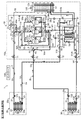
図1に示すように、冷凍装置(1)は、室外に設置される室外ユニット(10)と、室内空間を空調する室内ユニット(20)と、冷蔵倉庫の庫内を冷却する冷蔵ユニット(30)と、コントローラ(100)とを備えている。なお、室内ユニット(20)及び冷蔵ユニット(30)の数量は、1つに限らず、2つ以上であってもよい。そして、これらのユニットが接続されて冷媒回路(2)が構成されている。冷媒回路(2)には、大きく分けて、上記室内を空調するための空調系統回路(2a)と、上記冷蔵ユニット(30)及び冷凍ユニット(40)の庫内を冷却するための冷却系統回路(2b)とが形成されている。 As shown in FIG. 1, the refrigeration system (1) comprises an outdoor unit (10) installed outdoors, an indoor unit (20) for air conditioning the indoor space, and a refrigeration unit (30) for cooling the inside of the cold storage warehouse. And a controller (100). The number of the indoor units (20) and the refrigeration unit (30) is not limited to one, and may be two or more. Then, these units are connected to constitute a refrigerant circuit (2). The refrigerant circuit (2) is roughly divided into an air conditioning system circuit (2a) for air conditioning the room, and a cooling system circuit for cooling the inside of the cold storage unit (30) and the freezing unit (40). And (2b) are formed.
室外ユニット(10)には、室外熱交換器(12)を有する熱源側回路としての室外回路(11)が設けられている。室内ユニット(20)には、室内熱交換器(22)を有する室内回路(21)(利用側回路)が設けられている。冷蔵ユニット(30)には、冷蔵熱交換器(32)を有する冷蔵用回路(31)(利用側回路)が設けられている。 The outdoor unit (10) is provided with an outdoor circuit (11) as a heat source side circuit having an outdoor heat exchanger (12). The indoor unit (20) is provided with an indoor circuit (21) (use side circuit) having an indoor heat exchanger (22). The refrigeration unit (30) is provided with a refrigeration circuit (31) (use-side circuit) having a refrigeration heat exchanger (32).
冷凍装置(1)では、室外回路(11)と複数の利用側回路(21,31)が、第1ガス側連絡配管(51)、第1液側連絡配管(52)、第2ガス側連絡配管(53)、及び第2液側連絡配管(54)からなる4本の連絡配管(51〜54)で互いに接続され、蒸気圧縮式の冷凍サイクルを行う冷媒回路(2)が構成されている。 In the refrigeration system (1), the outdoor circuit (11) and the plurality of use side circuits (21, 31) are the first gas side communication pipe (51), the first liquid side communication pipe (52), the second gas side communication The refrigerant circuit (2) is connected to each other by four connecting pipes (51 to 54) consisting of a pipe (53) and a second liquid side connecting pipe (54), and a refrigerant circuit (2) performing a vapor compression refrigeration cycle is configured. .
第1ガス側連絡配管(51)は、一端が室外回路(11)の第1ガス側閉鎖弁(71)に接続され、他端が室内回路(21)のガス側端に接続されている。第1液側連絡配管(52)は、一端が室外回路(11)の第1液側閉鎖弁(72)に接続され、他端が室内回路(21)の液側端に接続されている。第2ガス側連絡配管(53)は、一端が室外回路(11)の第2ガス側閉鎖弁(73)に接続され、他端が冷蔵用回路(31)のガス側端に接続されている。第2液側連絡配管(54)は、一端が室外回路(11)の第2液側閉鎖弁(74)に接続され、他端が冷蔵用回路(31)の液側端に接続されている。 One end of the first gas side connection pipe (51) is connected to the first gas side closing valve (71) of the outdoor circuit (11), and the other end is connected to the gas side end of the indoor circuit (21). One end of the first liquid side communication pipe (52) is connected to the first liquid side closing valve (72) of the outdoor circuit (11), and the other end is connected to the liquid side end of the indoor circuit (21). One end of the second gas side communication pipe (53) is connected to the second gas side closing valve (73) of the outdoor circuit (11), and the other end is connected to the gas side end of the refrigeration circuit (31) . One end of the second liquid side communication pipe (54) is connected to the second liquid side closing valve (74) of the outdoor circuit (11), and the other end is connected to the liquid side end of the refrigeration circuit (31) .
〈室外ユニット〉
室外ユニット(10)は、屋外に設置され、上記室外回路(11)と、該室外回路(11)を収容する室外ケーシング(10a)とを有している。室外回路(11)は、上記室外熱交換器(12)と、圧縮機構(13)と、室外膨張弁(14)(膨張機構)と、レシーバ(15)と、油分離器(16)と、第1,第2及び第3四路切換弁(17,18,19)(切換機構)と、上記の4つの閉鎖弁(71,72,73,74)とを備えている。
<Outdoor unit>
The outdoor unit (10) is installed outdoors, and has the outdoor circuit (11) and an outdoor casing (10a) accommodating the outdoor circuit (11). The outdoor circuit (11) includes the outdoor heat exchanger (12), a compression mechanism (13), an outdoor expansion valve (14) (expansion mechanism), a receiver (15), and an oil separator (16). The first, second and third four-way selector valves (17, 18, 19) (switching mechanism) and the above-mentioned four closing valves (71, 72, 73, 74) are provided.
圧縮機構(13)は、第1〜第3圧縮機(13a,13b,13c)を有している。第1〜第3圧縮機(13a,13b,13c)は、いずれも固定スクロール及び可動スクロールが噛み合って圧縮室が形成される全密閉型のスクロール圧縮機である。第1〜第3圧縮機(13a,13b,13c)では、各圧縮室の吸入位置において吸入ポート(図示省略)が開口し、吐出位置において吐出ポート(図示省略)が開口し、中間位置において中間ポート(図示省略)が開口している。 The compression mechanism (13) has first to third compressors (13a, 13b, 13c). The first to third compressors (13a, 13b, 13c) are all hermetic scroll compressors in which a fixed scroll and a movable scroll are engaged to form a compression chamber. In the first to third compressors (13a, 13b, 13c), a suction port (not shown) is opened at the suction position of each compression chamber, a discharge port (not shown) is opened at the discharge position, A port (not shown) is open.
上記第1圧縮機(冷却側圧縮機)(13a)及び第3圧縮機(空調側圧縮機)(13c)は、可変容量型の圧縮機である。つまり、第1圧縮機(13a)及び第3圧縮機(13c)は、インバータ制御によって回転速度が可変に構成されている。一方、第2圧縮機(13b)は、回転速度が一定の固定容量型の圧縮機であり、主に第1圧縮機(13a)の補助に用いられるが、第3圧縮機(13c)の補助に用いることもできる。なお、第2圧縮機(13b)は、可変容量型の圧縮機であってもよい。また、上記第1〜第3圧縮機(13a,13b,13c)には、吸入側に吸入配管(55)が接続される一方、吐出側に吐出配管(56)が接続されている。吐出配管(56)には、異常高圧時に圧縮機(13a,13b,13c)を緊急停止させるための高圧圧力スイッチ(110)が設けられている。 The first compressor (cooling side compressor) (13a) and the third compressor (air conditioning side compressor) (13c) are variable displacement compressors. That is, the rotational speeds of the first compressor (13a) and the third compressor (13c) are configured to be variable by inverter control. On the other hand, the second compressor (13b) is a fixed displacement compressor having a constant rotational speed, and is mainly used for assisting the first compressor (13a), but for assisting the third compressor (13c) It can also be used for The second compressor (13b) may be a variable displacement compressor. Further, a suction pipe (55) is connected to the suction side of the first to third compressors (13a, 13b, 13c), and a discharge pipe (56) is connected to the discharge side. The discharge pipe (56) is provided with a high pressure switch (110) for urgently stopping the compressor (13a, 13b, 13c) under abnormal high pressure.
吸入配管(55)は、流入側が第1流入分岐管(55a)と第2流入分岐管(55b)とに分岐している。第1流入分岐管(55a)は上記第2ガス側閉鎖弁(73)に第3四路切換弁(19)を介して接続される一方、第2流入分岐管(55b)は第2四路切換弁(18)の第2ポート(P2)に接続されている。第1流入分岐管(55a)と第2流入分岐管(55b)は、流入連通管(66)によって互いに接続され、流入連通管(66)には、上記第3圧縮機(空調側圧縮機)(13c)の吸入冷媒量と上記第1圧縮機(冷却側圧縮機)(13a)の吸入冷媒量を調整可能な圧力調整弁(67)(流量調整弁)が設けられている。 The inflow side of the suction pipe (55) branches into a first inflow branch pipe (55a) and a second inflow branch pipe (55b). The first inflow branch pipe (55a) is connected to the second gas side shut-off valve (73) via the third four-way selector valve (19), while the second inflow branch pipe (55b) is connected to the second four path It is connected to the second port (P2) of the switching valve (18). The first inflow branch pipe (55a) and the second inflow branch pipe (55b) are connected to each other by the inflow communication pipe (66), and the third communication compressor (air conditioning side compressor) is connected to the inflow communication pipe (66). A pressure control valve (67) (flow rate control valve) is provided which can adjust the amount of refrigerant drawn in (13c) and the amount of refrigerant drawn in the first compressor (cooling side compressor) (13a).
また、吸入配管(55)は、流出側が第1流出分岐管(55c)(第1吸入分岐管)と第2流出分岐管(55d)(第2吸入分岐管)と第3流出分岐管(55e)(第3吸入分岐管)とに分岐している。第1流出分岐管(55c)は上記第1圧縮機(13a)の吸入側端に接続され、第2流出分岐管(55d)は上記第2圧縮機(13b)の吸入側端に接続され、第3流出分岐管(55e)は上記第3圧縮機(13c)の吸入側端に接続されている。 The suction pipe (55) has a first outflow branch pipe (55c) (first suction branch pipe), a second outflow branch pipe (55d) (second suction branch pipe), and a third outflow branch pipe (55e) on the outflow side. ) (The third suction branch pipe). The first outflow branch pipe (55c) is connected to the suction side end of the first compressor (13a), and the second outflow branch pipe (55d) is connected to the suction side end of the second compressor (13b), The third outflow branch pipe (55e) is connected to the suction side end of the third compressor (13c).
吐出配管(56)は、流入側が第1流入分岐管(56a)と第2流入分岐管(56b)と第3流入分岐管(56c)とに分岐している。第1流入分岐管(56a)は上記第1圧縮機(13a)の吐出側端に接続され、第2流入分岐管(56b)は上記第2圧縮機(13b)の吐出側端に接続され、第3流入分岐管(56c)は上記第3圧縮機(13c)の吐出側端に接続されている。第1〜第3流入分岐管(56a,56b,56c)には、それぞれに逆止弁(CV1,CV2,CV3)が設けられている。これらの逆止弁(CV1,CV2,CV3)は、第1〜第3圧縮機(13a,13b,13c)から四路切換弁(17,18,19)へ向かう冷媒の流通を許容し、逆方向への冷媒の流通を阻止する。また、吐出配管(56)は、流出側が第1流出分岐管(56d)と第2流出分岐管(56e)と第3流出分岐管(56f)とに分岐している。第1流出分岐管(56d)は第1四路切換弁(17)の第1ポート(P1)に接続され、第2流出分岐管(56e)は第2四路切換弁(18)の第1ポート(P1)に接続され、第3流出分岐管(56f)は第3四路切換弁(19)の第1ポート(P1)に接続されている。 The inflow side of the discharge pipe (56) branches into a first inflow branch pipe (56a), a second inflow branch pipe (56b), and a third inflow branch pipe (56c). The first inflow branch pipe (56a) is connected to the discharge side end of the first compressor (13a), and the second inflow branch pipe (56b) is connected to the discharge side end of the second compressor (13b), The third inflow branch pipe (56c) is connected to the discharge side end of the third compressor (13c). The first to third inflow branch pipes (56a, 56b, 56c) are respectively provided with check valves (CV1, CV2, CV3). These check valves (CV1, CV2, CV3) allow the refrigerant to flow from the first to third compressors (13a, 13b, 13c) to the four-way selector valve (17, 18, 19), and reversely Prevent the flow of refrigerant in the direction. The discharge pipe (56) has an outflow side branched into a first outflow branch pipe (56d), a second outflow branch pipe (56e), and a third outflow branch pipe (56f). The first outflow branch pipe (56d) is connected to the first port (P1) of the first four-way selector valve (17), and the second outflow branch pipe (56e) is connected to the first one of the second four-way selector valve (18). The third outflow branch pipe (56f) is connected to the port (P1), and is connected to the first port (P1) of the third four-way selector valve (19).
油分離器(16)は、吐出配管(56)の中途部に設けられている。油分離器(16)は、第1〜第3圧縮機(13a,13b,13c)から吐出される冷媒に混じった潤滑油を分離し、該潤滑油を第1〜第3圧縮機(13a,13b,13c)に返送する。具体的には、油分離器(16)において冷媒から分離された潤滑油は、油分離器(16)に接続された油戻し配管(50)を介して後述するインジェクション配管(81)の流入端側に返送される。油戻し配管(50)には流量調整弁(48)が設けられている。 The oil separator (16) is provided in the middle of the discharge pipe (56). The oil separator (16) separates the lubricating oil mixed with the refrigerant discharged from the first to third compressors (13a, 13b, 13c), and the lubricating oil is separated from the first to third compressors (13a, 13a, 13c). Return to 13b, 13c). Specifically, the lubricating oil separated from the refrigerant in the oil separator (16) is introduced into the inflow end of an injection pipe (81) described later via an oil return pipe (50) connected to the oil separator (16). It will be returned to the side. The oil return pipe (50) is provided with a flow control valve (48).
第1,第2及び第3四路切換弁(17,18,19)は、第1ポート(P1)が第3ポート(P3)に連通し且つ第2ポート(P2)が第4ポート(P4)に連通する第1状態(図1に実線で示す状態)と、第1ポート(P1)が第4ポート(P4)に連通し且つ第2ポート(P2)が第3ポート(P3)に連通する第2状態(図1に破線で示す状態)とに切り換わる。上記冷凍装置は、この第1,第2及び第3四路切換弁(17,18,19)の切換動作によって、様々な運転を行うことができる。 The first, second and third four-way selector valves (17, 18, 19) communicate the first port (P1) with the third port (P3) and the second port (P2) with the fourth port (P4). And the first port (P1) communicates with the fourth port (P4) and the second port (P2) communicates with the third port (P3). Switching to the second state (indicated by the broken line in FIG. 1). The refrigeration system can perform various operations by the switching operation of the first, second and third four-way selector valves (17, 18, 19).
第1四路切換弁(17)の第1ポート(P1)には第1流出分岐管(56d)が接続されている。第1四路切換弁(17)の第2ポート(P2)は、第2四路切換弁(18)の第3ポート(P3)に接続されている。第1四路切換弁(17)の第3ポート(P3)は、冷媒配管を介して第1ガス側閉鎖弁(71)に接続されている。第1四路切換弁(17)の第4ポート(P4)は、室外ガス配管(58)を介して室外熱交換器(12)のガス側端に接続されている。 A first outflow branch pipe (56d) is connected to a first port (P1) of the first four-way selector valve (17). The second port (P2) of the first four-way selector valve (17) is connected to the third port (P3) of the second four-way selector valve (18). The third port (P3) of the first four-way selector valve (17) is connected to the first gas side shut-off valve (71) via a refrigerant pipe. The fourth port (P4) of the first four-way selector valve (17) is connected to the gas side end of the outdoor heat exchanger (12) via the outdoor gas pipe (58).
第2四路切換弁(18)の第1ポート(P1)には第2流出分岐管(56e)が接続されている。第2四路切換弁(18)の第2ポート(P2)は、上述したように第2流入分岐管(55b)に接続されている。第2四路切換弁(18)の第3ポート(P3)は、上述したように第1四路切換弁(17)の第2ポート(P2)に接続されている。第2四路切換弁(18)の第4ポート(P4)は閉鎖された閉鎖ポートになっている。 A second outflow branch pipe (56e) is connected to a first port (P1) of the second four-way selector valve (18). The second port (P2) of the second four-way selector valve (18) is connected to the second inflow branch pipe (55b) as described above. The third port (P3) of the second four-way selector valve (18) is connected to the second port (P2) of the first four-way selector valve (17) as described above. The fourth port (P4) of the second four-way selector valve (18) is a closed port that is closed.
第3四路切換弁(19)の第1ポート(P1)には第3流出分岐管(56f)が接続されている。第3四路切換弁(19)の第2ポート(P2)は、第1流入分岐管(55a)に接続されている。第3四路切換弁(19)の第3ポート(P3)は、開閉弁(64)が設けられた接続配管(65)を介して、レシーバ(15)への冷媒流入管である後述の第4液管(79)に接続され、第3四路切換弁(19)の第4ポート(P4)は、冷媒配管を介して第2ガス側閉鎖弁(73)に接続されている。 A third outflow branch pipe (56f) is connected to a first port (P1) of the third four-way selector valve (19). The second port (P2) of the third four-way selector valve (19) is connected to the first inflow branch pipe (55a). The third port (P3) of the third four-way selector valve (19) is a refrigerant inflow pipe to the receiver (15) via the connection pipe (65) provided with the on-off valve (64). It is connected to the four liquid pipe (79), and the fourth port (P4) of the third four-way selector valve (19) is connected to the second gas side closing valve (73) via the refrigerant pipe.
室外熱交換器(12)は、フィン・アンド・チューブ型の熱交換器であり、近傍に室外ファン(12a)が設けられている。この室外熱交換器(12)では、内部を流れる冷媒と室外ファン(12a)が送風する外気との間で熱交換が行われる。室外ファン(12a)は、室外回路(11)と共に室外ケーシング(10a)内に収容されている。 The outdoor heat exchanger (12) is a fin-and-tube type heat exchanger, and an outdoor fan (12a) is provided in the vicinity. In the outdoor heat exchanger (12), heat exchange is performed between the refrigerant flowing inside and the outside air blown by the outdoor fan (12a). The outdoor fan (12a) is accommodated in the outdoor casing (10a) together with the outdoor circuit (11).
室外熱交換器(12)は、液側端が第1液管(59)を介してレシーバ(15)の頂部に接続されている。レシーバ(15)の底部は、レシーバ(15)の底部は、室外熱交換器(12)の底部の凍結防止管(57)と、この凍結防止管(57)に接続された過冷却熱交換器(76)が設けられた第2液管(60)とを介して第2液側閉鎖弁(74)に接続されている。また、第2液管(60)における凍結防止管(57)と過冷却熱交換器(76)との間の部分は、第3液管(62)を介して第1液側閉鎖弁(72)に接続されている。 The outdoor heat exchanger (12) has a liquid side end connected to the top of the receiver (15) via a first liquid pipe (59). The bottom of the receiver (15), the bottom of the receiver (15), the antifreeze pipe (57) at the bottom of the outdoor heat exchanger (12), and the supercooling heat exchanger connected to the antifreeze pipe (57) It is connected to the 2nd liquid side closing valve (74) via the 2nd liquid pipe (60) in which (76) was provided. Further, a portion of the second liquid pipe (60) between the antifreeze pipe (57) and the subcooling heat exchanger (76) is connected to the first liquid side shut-off valve (72) through the third liquid pipe (62). )It is connected to the.
第1液管(59)には室外膨張弁(14)が設けられている。室外膨張弁(14)は、開度が調節可能な電子膨張弁によって構成されている。 An outdoor expansion valve (14) is provided in the first liquid pipe (59). The outdoor expansion valve (14) is configured by an electronic expansion valve whose opening degree can be adjusted.
第1液管(59)及び第3液管(62)には、には、それぞれ逆止弁(CV4,CV5)が設けられている。第1液管(59)の逆止弁(CV4)は、室外熱交換器(12)からレシーバ(15)の頂部へ向かう冷媒の流通を許容し、逆方向への冷媒の流通を阻止する。第3液管(60)の逆止弁(CV5)は、凍結防止管(57)から第1液側閉鎖弁(72)に向かう冷媒の流通を許容し、逆方向への冷媒の流通を阻止する。 The first liquid pipe (59) and the third liquid pipe (62) are provided with check valves (CV4, CV5), respectively. The check valve (CV4) of the first liquid pipe (59) allows the refrigerant to flow from the outdoor heat exchanger (12) to the top of the receiver (15) and prevents the refrigerant from flowing in the reverse direction. The check valve (CV5) of the third liquid pipe (60) allows the refrigerant to flow from the antifreeze pipe (57) toward the first liquid side shut-off valve (72) and prevents the refrigerant from flowing in the reverse direction Do.
第1液管(59)と第2液管(60)との間には、バイパス管(61)が設けられている。バイパス管(61)は、一端が第1液管(59)の逆止弁(CV4)の上流側に接続され、他端が第2液管(60)の(CV9)の上流側に接続されている。バイパス管(61)には逆止弁(CV8)が設けられ、室外熱交換器(12)へ向かう冷媒の流れを許容し、逆方向への冷媒の流れを禁止する。バイパス管(61)と第2液側閉鎖弁(74)との間には、バイパス管(61)から第2液側閉鎖弁(74)へ向かう冷媒の流れを許容し、逆方向への冷媒の流れを禁止する逆止弁(CV9)が設けられている。 A bypass pipe (61) is provided between the first liquid pipe (59) and the second liquid pipe (60). One end of the bypass pipe (61) is connected to the upstream side of the check valve (CV4) of the first liquid pipe (59), and the other end is connected to the upstream side of (CV9) of the second liquid pipe (60) ing. The bypass pipe (61) is provided with a check valve (CV8) to allow the flow of the refrigerant toward the outdoor heat exchanger (12) and to prohibit the flow of the refrigerant in the reverse direction. Between the bypass pipe (61) and the second liquid side shut-off valve (74), allow the flow of the refrigerant from the bypass pipe (61) to the second liquid side shut-off valve (74). A check valve (CV9) for inhibiting the flow of
過冷却熱交換器(76)は、高圧側流路(76a)と低圧側流路(76b)とを備えている。過冷却熱交換器(76)は、高圧側流路(76a)及び低圧側流路(76b)を流れる冷媒同士が熱交換して高圧側流路(76a)の冷媒が過冷却されるように構成されている。低圧側流路(76b)は、詳細は後述するインジェクション配管(81)の主管(77)の一部を構成している。 The subcooling heat exchanger (76) includes a high pressure side flow passage (76a) and a low pressure side flow passage (76b). In the subcooling heat exchanger (76), the refrigerant flowing in the high pressure side flow passage (76a) and the low pressure side flow passage (76b) exchanges heat so that the refrigerant in the high pressure side flow passage (76a) is supercooled. It is configured. The low pressure side flow passage (76b) constitutes a part of a main pipe (77) of an injection pipe (81) which will be described in detail later.
主管(77)の低圧側流路(76b)の上流側には流量調節弁(78)が設けられている。流量調節弁(78)は、開度が調節可能な電子膨張弁で構成されている。流量調節弁(78)は、インジェクション配管(81)を流れる冷媒の流量を調節する流量調節弁を構成する。第2液管(60)は、液冷媒が流れる液ラインの一部を構成する。 A flow rate control valve (78) is provided on the upstream side of the low pressure side channel (76b) of the main pipe (77). The flow rate control valve (78) is composed of an electronic expansion valve whose opening degree can be adjusted. The flow rate control valve (78) constitutes a flow rate control valve that controls the flow rate of the refrigerant flowing through the injection pipe (81). The second liquid pipe (60) constitutes a part of a liquid line through which the liquid refrigerant flows.
第3液管(62)の逆止弁(CV5)の下流側と第1液管(59)の逆止弁(CV4)の下流側との間には、第4液管(79)が設けられている。第4液管(79)には、逆止弁(CV6)が設けられている。逆止弁(CV6)は、第2液管(60)から第1液管(59)へ向かう冷媒の流通を許容し、逆方向への冷媒の流通を阻止する。 A fourth liquid pipe (79) is provided between the downstream side of the check valve (CV5) of the third liquid pipe (62) and the downstream side of the check valve (CV4) of the first liquid pipe (59). It is done. The fourth liquid pipe (79) is provided with a check valve (CV6). The check valve (CV6) allows the flow of the refrigerant from the second liquid pipe (60) to the first liquid pipe (59), and prevents the flow of the refrigerant in the reverse direction.
室外回路(11)には、逆サイクルデフロスト運転時の冷媒戻り配管(80)が設けられている。冷媒戻り配管(80)は、一端が第2液側閉鎖弁(74)とバイパス管(61)との間に接続され、他端が第4液管(79)における第1液管(59)と接続配管(65)との間で接続されている。冷媒戻り配管(80)には、レシーバ(15)へ向かう冷媒の流れを許容し、逆方向への冷媒の流れを禁止する逆止弁(CV10)が設けられている。 The outdoor circuit (11) is provided with a refrigerant return pipe (80) during reverse cycle defrost operation. One end of the refrigerant return pipe (80) is connected between the second liquid side closing valve (74) and the bypass pipe (61), and the other end is a first liquid pipe (59) in the fourth liquid pipe (79). And connection piping (65) are connected. The refrigerant return pipe (80) is provided with a check valve (CV10) which allows the flow of the refrigerant toward the receiver (15) and prohibits the flow of the refrigerant in the reverse direction.
インジェクション配管(81)は、液ラインである第2液管(60)に繋がる主管(77)と、該主管(77)の流出端から分岐する第1〜第3インジェクション管(81a,81b,81c)とを有している。各インジェクション管(81a,81b,81c)は、各圧縮機(13a,13b,13c)の中間圧の圧縮室に連通する中間圧ポートに接続されている。第1インジェクション管(81a)には第1膨張弁(82a)が、第2インジェクション管(81b)には第2膨張弁(82b)が、第3インジェクション管(81c)には第3膨張弁(82c)がそれぞれ接続される。各膨張弁(82a,82b,82c)は、開度可変の電子膨張弁によって構成されている。各インジェクション管(81a,81b,81c)は、過冷却熱交換器(76)から各圧縮機(13a,13b,13c)の中間圧の圧縮室へガス冷媒を導入するインジェクション回路を構成している。 The injection pipe (81) includes a main pipe (77) connected to a second liquid pipe (60) which is a liquid line, and first to third injection pipes (81a, 81b, 81c) branched from the outflow end of the main pipe (77). And. Each injection pipe (81a, 81b, 81c) is connected to an intermediate pressure port communicating with a compression chamber at an intermediate pressure of each compressor (13a, 13b, 13c). The first expansion valve (82a) is for the first injection pipe (81a), the second expansion valve (82b) for the second injection pipe (81b), and the third expansion valve (for the third injection pipe (81c). 82c) are connected respectively. Each expansion valve (82a, 82b, 82c) is comprised by the electronic expansion valve of opening degree variable. Each injection pipe (81a, 81b, 81c) constitutes an injection circuit for introducing the gas refrigerant from the subcooling heat exchanger (76) into the compression chamber at an intermediate pressure of each compressor (13a, 13b, 13c) .
室外回路(11)には、各種センサが設けられている。例えば、吐出配管(56)には、各圧縮機(13a,13b,13c)の吐出冷媒の温度をそれぞれ検出する吐出温度センサ(111a, 111b,
111c)と、各圧縮機(13a,13b,13c)の吐出冷媒の圧力を検出する吐出圧力センサ(112)とが設けられている。これらの吐出温度センサ(111a,111b, 111c)は、第1圧縮機(13a)に対応する第1吐出温度センサ(111a)と、第2圧縮機(13b)に対応する第2吐出温度センサ(111b)と、第3圧縮機(13c)に対応する第3吐出温度センサ(111c)とで構成される。また、吸入配管(55)には、各圧縮機(13a,13b,13c)の吸入冷媒の温度を検出する吸入温度センサ(113)と、各圧縮機(13a,13b,13c)の吸入冷媒の圧力を検出する吸入圧力センサ(114)が設けられている。
Various sensors are provided in the outdoor circuit (11). For example, in the discharge pipe (56), discharge temperature sensors (111a, 111b,
111c) and a discharge pressure sensor (112) for detecting the pressure of the refrigerant discharged from each of the compressors (13a, 13b, 13c). The discharge temperature sensors (111a, 111b, 111c) correspond to the first discharge temperature sensor (111a) corresponding to the first compressor (13a) and the second discharge temperature sensor (111) corresponding to the second compressor (13b). And 111b) and a third discharge temperature sensor (111c) corresponding to the third compressor (13c). In the suction pipe (55), a suction temperature sensor (113) for detecting the temperature of the suction refrigerant of each compressor (13a, 13b, 13c) and the suction refrigerant of each compressor (13a, 13b, 13c) A suction pressure sensor (114) is provided to detect pressure.
室外熱交換器(12)の近傍には、室外の外気温度を検出する室外温度センサ(115)が設けられている。室外熱交換器(12)の液側端部には、第1温度センサ(118)が設けられている。主管(77)には、圧力センサ(117)が設けられている。また、第2液管(60)には、レシーバ(15)の圧力を検出する圧力センサ(119)が設けられている。これらのセンサの検出値は、後述するコントローラ(100)に入力される。 In the vicinity of the outdoor heat exchanger (12), an outdoor temperature sensor (115) for detecting the outdoor air temperature outside the room is provided. A first temperature sensor (118) is provided at the liquid side end of the outdoor heat exchanger (12). The main pipe (77) is provided with a pressure sensor (117). Further, the second liquid pipe (60) is provided with a pressure sensor (119) for detecting the pressure of the receiver (15). The detection values of these sensors are input to a controller (100) described later.
〈室内ユニット〉
室内ユニット(20)は、室内に設置され、室内回路(21)と、室内回路(21)を収容する室内ケーシング(20a)とを有している。室内回路(21)は、ガス側端が第1ガス側連絡配管(51)に接続され、液側端が第1液側連絡配管(52)に接続されている。室内回路(21)には、ガス側端から順に、室内熱交換器(22)及び室内膨張弁(23)(膨張機構)が設けられている。室内熱交換器(22)は、クロスフィン式のフィン・アンド・チューブ型熱交換器によって構成され、近傍に室内ファン(22a)が設けられている。室内ファン(22a)は、室内回路(21)と共に室内ケーシング(20a)内に収容されている。室内熱交換器(22)では、内部を流れる冷媒と室内ファン(22a)が送風する室内空気との間で熱交換が行われる。
<Indoor unit>
The indoor unit (20) is installed indoors and has an indoor circuit (21) and an indoor casing (20a) that accommodates the indoor circuit (21). The indoor circuit (21) has a gas side end connected to the first gas side communication pipe (51) and a liquid side end connected to the first liquid side communication pipe (52). The indoor heat exchanger (22) and the indoor expansion valve (23) (expansion mechanism) are provided in the indoor circuit (21) in order from the gas side end. The indoor heat exchanger (22) is constituted by a cross fin type fin-and-tube heat exchanger, and an indoor fan (22a) is provided in the vicinity. The indoor fan (22a) is housed in the indoor casing (20a) together with the indoor circuit (21). In the indoor heat exchanger (22), heat exchange is performed between the refrigerant flowing inside and the indoor air blown by the indoor fan (22a).
室内膨張弁(23)は、開度が調節可能な電子膨張弁によって構成されている。室内熱交換器(22)の近傍には、室内空気の温度を検出する室内温度センサ(121)が設けられている。室内回路(21)では、室内熱交換器(22)の伝熱管に、第2温度センサ(122)が設けられている。また、室内回路(21)におけるガス側端の近傍に、蒸発温度センサ(123)が設けられている。 The indoor expansion valve (23) is constituted by an electronic expansion valve whose opening degree can be adjusted. In the vicinity of the indoor heat exchanger (22), an indoor temperature sensor (121) for detecting the temperature of the indoor air is provided. In the indoor circuit (21), a heat transfer pipe of the indoor heat exchanger (22) is provided with a second temperature sensor (122). Further, an evaporation temperature sensor (123) is provided in the vicinity of the gas side end of the indoor circuit (21).
〈冷蔵ユニット〉
冷蔵ユニット(30)は、上記冷蔵用回路(31)と、該冷蔵用回路(31)を収容する冷蔵庫(30a)とを有している。
<Colder unit>
The refrigeration unit (30) has the refrigeration circuit (31) and a refrigerator (30a) for accommodating the refrigeration circuit (31).
冷蔵ユニット(30)の冷蔵用回路(31)は、ガス側端が第2ガス側連絡配管(53)の第1分岐ガス管(53a)に接続され、液側端が第2液側連絡配管(54)の第1分岐液管(54a)に接続されている。冷蔵用回路(31)には、ガス側端から順に、冷蔵熱交換器(32)及び冷蔵膨張弁(33)(膨張機構)が設けられている。冷蔵熱交換器(32)は、クロスフィン式のフィン・アンド・チューブ型熱交換器によって構成され、近傍に庫内ファン(32a)が設けられている。庫内ファン(32a)は、冷蔵用回路(31)と共に冷蔵庫(30a)内に収容されている。冷蔵熱交換器(32)では、内部を流れる冷媒と庫内ファン(32a)が送風する冷蔵庫(30a)内の庫内空気との間で熱交換が行われる。冷蔵膨張弁(33)は、開度が調節可能な電子膨張弁により構成されている。また、冷蔵熱交換器(32)の近傍には、庫内空気の温度を検出する庫内温度センサ(131)が設けられている。また、冷蔵熱交換器(32)の伝熱管に、蒸発温度センサ(132)が設けられている。また、冷蔵用回路(31)におけるガス側端の近傍に、ガス温度センサ(133)が設けられている。 In the refrigeration circuit (31) of the refrigeration unit (30), the gas side end is connected to the first branch gas pipe (53a) of the second gas side communication pipe (53), and the liquid side end is the second liquid side communication pipe It is connected to the first branched liquid pipe (54a) of (54). The refrigeration circuit (31) is provided with a refrigeration heat exchanger (32) and a refrigeration expansion valve (33) (expansion mechanism) in this order from the gas side end. The cold storage heat exchanger (32) is constituted by a cross fin type fin-and-tube heat exchanger, and an internal fan (32a) is provided in the vicinity. The internal fan (32a) is housed in the refrigerator (30a) together with the circuit for refrigeration (31). In the refrigeration heat exchanger (32), heat exchange is performed between the refrigerant flowing inside and the air inside the refrigerator (30a) which the inside fan (32a) blows. The cold storage expansion valve (33) is constituted by an electronic expansion valve whose opening degree can be adjusted. Further, an in-compartment temperature sensor (131) for detecting the temperature of the in-compartment air is provided in the vicinity of the cold storage heat exchanger (32). Moreover, the evaporation temperature sensor (132) is provided in the heat transfer tube of the refrigeration heat exchanger (32). In addition, a gas temperature sensor (133) is provided in the vicinity of the gas side end of the refrigeration circuit (31).
〈コントローラ〉
コントローラ(100)(制御部)は、マイクロコンピュータと、該マイクロコンピュータを動作させるためのソフトウエアを格納するメモリディバイス(具体的には半導体メモリ)とを用いて構成されている。コントローラ(100)は、冷凍装置(1)の各機器を制御する。
<controller>
The controller (100) (control unit) is configured using a microcomputer and a memory device (specifically, a semiconductor memory) that stores software for operating the microcomputer. The controller (100) controls each device of the refrigeration system (1).
コントローラ(100)による各機器の制御により、冷凍装置(1)の各運転が切り換えられる。冷凍装置(1)は、室内ユニット(20)で室内を冷房する冷房運転と、室内ユニット(20)で室内を暖房する暖房運転とを行う。 Each operation of the refrigeration system (1) is switched by control of each device by the controller (100). The refrigeration system (1) performs a cooling operation to cool the room with the indoor unit (20) and a heating operation to heat the room with the indoor unit (20).
冷房運転では、室内ユニット(20)で室内空気を冷却すると同時に冷蔵ユニット(30)及び冷凍ユニット(40)で庫内空気を冷却する冷房冷却運転を含む。暖房運転は、第1暖房冷却運転、第2暖房冷却運転、及び第3暖房冷却運転を含む。第1暖房冷却運転では、室外熱交換器(12)が実質的に停止状態となると同時に冷蔵ユニット(30)で庫内空気を冷却する。第2暖房冷却運転では、室外熱交換器(12)が凝縮器になると同時に冷蔵ユニット(30)で庫内空気を冷却する。第3暖房冷却運転では、室外熱交換器(12)が蒸発器になると同時に冷蔵ユニット(30)で庫内空気を冷却する。 In the cooling operation, the cooling operation includes cooling the room air by the indoor unit (20) and simultaneously cooling the air in the cold storage unit (30) and the freezing unit (40). The heating operation includes a first heating / cooling operation, a second heating / cooling operation, and a third heating / cooling operation. In the first heating / cooling operation, the outdoor heat exchanger (12) is substantially stopped and, at the same time, the inside air is cooled by the refrigeration unit (30). In the second heating and cooling operation, the outdoor heat exchanger (12) becomes a condenser and at the same time, the refrigeration unit (30) cools the internal air. In the third heating and cooling operation, the outdoor heat exchanger (12) becomes an evaporator and at the same time, the refrigeration unit (30) cools the air in the cold storage.
また、冷房運転及び暖房運転では、冷蔵ユニット(30)の冷蔵熱交換器(32)を除霜するデフロスト運転がそれぞれ実行される。 Further, in the cooling operation and the heating operation, the defrosting operation for defrosting the refrigeration heat exchanger (32) of the refrigeration unit (30) is executed respectively.
図8に示すように、コントローラ(100)は、入力部(101)、演算部(102)、判定部(103)、及び出力部(104)を有している。 As shown in FIG. 8, the controller (100) includes an input unit (101), an arithmetic unit (102), a determination unit (103), and an output unit (104).
入力部(101)には、各センサの検出値や各機器の状態を示す信号が入力される。より詳細には、本実施形態の入力部(101)には、吐出圧力センサ(112)で検出した吐出冷媒の圧力と、吐出温度センサ(111a,111b,111c)で検出される各吐出冷媒の温度と、吸入圧力センサ(114)で検出される吸入冷媒の圧力が検出される。 A signal indicating the detection value of each sensor or the state of each device is input to the input unit (101). More specifically, in the input section (101) of the present embodiment, the pressure of the discharge refrigerant detected by the discharge pressure sensor (112) and the pressure of each discharge refrigerant detected by the discharge temperature sensor (111a, 111b, 111c) The temperature and the pressure of the suction refrigerant detected by the suction pressure sensor (114) are detected.
演算部(102)は、各センサの検出値に基づいて、流量調節弁(78)の開度を調節するための指標を求める。具体的に、演算部(102)は、運転中の圧縮機(13a,13b,13c)に対応する吐出冷媒の温度(Td)を求める。ここで、吐出冷媒の温度(Td)は、第1吐出温度センサ(111a)、第2吐出温度センサ(111b)、及び第3吐出温度センサ(111c)の検出温度に基づいて求めることができる。 The calculation unit (102) obtains an index for adjusting the opening degree of the flow rate control valve (78) based on the detection value of each sensor. Specifically, the calculation unit (102) obtains the temperature (Td) of the discharged refrigerant corresponding to the operating compressor (13a, 13b, 13c). Here, the temperature (Td) of the discharge refrigerant can be obtained based on the temperatures detected by the first discharge temperature sensor (111a), the second discharge temperature sensor (111b), and the third discharge temperature sensor (111c).
また、演算部(102)は、この吐出冷媒の温度(Td)と、吐出冷媒の圧力に相当する飽和温度とに基づいて、運転中の圧縮機(13a,13b,13c)に対応する吐出冷媒の吐出過熱度(TdSH)を算出する。更に、演算部(102)は、冷媒回路(2)の高圧圧力と低圧圧力との差(高低差圧(ΔP))を差算出する。この高低差圧(ΔP)は、吐出圧力センサ(112)で検出した吐出冷媒の圧力と、吸入圧力センサ(114)で検出した吸入冷媒の圧力との差で得られる。 In addition, the calculation unit (102) calculates the discharge refrigerant corresponding to the operating compressor (13a, 13b, 13c) based on the temperature (Td) of the discharge refrigerant and the saturation temperature corresponding to the pressure of the discharge refrigerant. Calculate the discharge superheat degree (TdSH) of Furthermore, the calculation unit (102) calculates a difference between the high pressure and the low pressure of the refrigerant circuit (2) (high-low differential pressure (ΔP)). The level difference pressure (ΔP) is obtained by the difference between the pressure of the discharge refrigerant detected by the discharge pressure sensor (112) and the pressure of the suction refrigerant detected by the suction pressure sensor (114).
判定部(103)は、上述した各指標(吐出温度(Td)、吐出過熱度(TdSH)、及び高低差圧ΔP)と、所定値とを比較して、流量調節弁(78)の開度を調節するための制御を行う(詳細は後述する)。 The determination unit (103) compares the above-mentioned indexes (discharge temperature (Td), discharge superheat degree (TdSH), and differential pressure ΔP) with a predetermined value, and the opening degree of the flow rate control valve (78) Control to adjust (described later in detail).
−運転動作−
冷凍装置(1)では、冷房冷却運転、第1暖房冷却運転、第2暖房冷却運転、第3暖房冷却運転の各運転モードが、各四路切換弁(17,18,19)を切り換えることにより実行される。
-Driving operation-
In the refrigeration system (1), each operation mode of the cooling / cooling operation, the first heating / cooling operation, the second heating / cooling operation, and the third heating / cooling operation is switched by switching the four-way switching valves (17, 18, 19). To be executed.
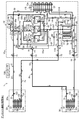
〈冷房冷却運転〉
図2に示す冷房冷却運転は、室内ユニット(20)の冷房と冷蔵ユニット(30)の冷却を行う運転である。コントローラ(100)は、第1,第2四路切換弁(17,18)を第2状態に切り換え、第3四路切換弁(19)を第1状態に切り換え、室外膨張弁(14)を全開状態に制御し、冷蔵膨張弁(33)、及び室内膨張弁(23)の開度を適宜調節する。また、開閉弁(64)と圧力調整弁(67)は全閉に制御される。
<Cooling cooling operation>
The cooling operation shown in FIG. 2 is an operation for cooling the indoor unit (20) and cooling the refrigeration unit (30). The controller (100) switches the first and second four-way selector valves (17, 18) to the second state, switches the third four-way selector valve (19) to the first state, and the outdoor expansion valve (14). It controls to a fully open state and adjusts the opening degree of a refrigeration expansion valve (33) and an indoor expansion valve (23) suitably. Further, the on-off valve (64) and the pressure control valve (67) are controlled to be fully closed.
冷媒回路(2)では以下のように冷媒が循環する。 In the refrigerant circuit (2), the refrigerant circulates as follows.
第1〜第3圧縮機(13a,13b,13c)で圧縮された冷媒は、吐出配管(56)において合流してから油分離器(16)において潤滑油が分離され、第1四路切換弁(17)及び室外ガス配管(58)を通過して室外熱交換器(12)に流入する。室外熱交換器(12)では、冷媒が室外空気に放熱して凝縮する。室外熱交換器(12)で凝縮した液冷媒は、第1液管(59)を介してレシーバ(15)に流入し、該レシーバ(15)に貯留される。 The refrigerant compressed by the first to third compressors (13a, 13b, 13c) merges in the discharge pipe (56) and then the lubricating oil is separated in the oil separator (16), and the first four-way switching valve (17) and the outdoor gas pipe (58) to flow into the outdoor heat exchanger (12). In the outdoor heat exchanger (12), the refrigerant releases heat to the outdoor air and condenses. The liquid refrigerant condensed in the outdoor heat exchanger (12) flows into the receiver (15) through the first liquid pipe (59) and is stored in the receiver (15).
レシーバ(15)に貯留された液冷媒は、レシーバ(15)から流出して凍結防止管(57)を通過し、第2液管(60)を第1液側閉鎖弁(72)及び第2液側閉鎖弁(74)に向かって分流する。その際に、液冷媒は過冷却熱交換器(76)を通過する。 The liquid refrigerant stored in the receiver (15) flows out of the receiver (15) and passes through the antifreeze pipe (57), and the second liquid pipe (60) is subjected to the first liquid side shut-off valve (72) and the second It diverts towards the liquid side shutoff valve (74). At that time, the liquid refrigerant passes through the subcooling heat exchanger (76).
高圧の液冷媒は、過冷却熱交換器(76)の高圧側流路(76a)に流入する。一方、過冷却熱交換器(76)の低圧側流路(76b)には高圧側流路(76a)を通過後に第2液管(60)から主管(77)に分岐して流量調節弁(78)で減圧された冷媒が流入する。低圧側流路(76b)を流れる冷媒は、高圧側流路(76a)を流れる高圧の液冷媒と熱交換して蒸発する一方、高圧側流路(76a)の高圧の液冷媒は、低圧側流路(76b)の冷媒に放熱することによって過冷却状態となる。第2液側閉鎖弁(74)を通過した冷媒は、第2液側連絡配管(54)に流入する。第1液側閉鎖弁(72)を通過した冷媒は、第1液側連絡配管(52)に流入する。蒸発した低圧側流路(76b)の冷媒は、インジェクション配管(81)に流入する。 The high pressure liquid refrigerant flows into the high pressure side flow passage (76a) of the subcooling heat exchanger (76). On the other hand, after passing through the high pressure side flow path (76a) to the low pressure side flow path (76b) of the subcooling heat exchanger (76), the second liquid pipe (60) is branched to the main pipe (77) The refrigerant depressurized in 78) flows in. The refrigerant flowing in the low pressure side flow passage (76b) exchanges heat with the high pressure liquid refrigerant flowing in the high pressure side flow passage (76a) and evaporates, while the high pressure liquid refrigerant in the high pressure side flow passage (76a) is evaporated on the low pressure side The heat is released to the refrigerant of the flow path (76 b) to be a supercooled state. The refrigerant that has passed through the second liquid side shut-off valve (74) flows into the second liquid side communication pipe (54). The refrigerant that has passed through the first liquid side shut-off valve (72) flows into the first liquid side communication pipe (52). The evaporated refrigerant in the low pressure side channel (76b) flows into the injection pipe (81).
第2液側連絡配管(54)に流入した液冷媒は、冷蔵ユニット(30)の冷蔵用回路(31)に流入する。冷蔵用回路(31)に流入した液冷媒は、冷蔵膨張弁(33)で減圧された後、冷蔵熱交換器(32)に流入する。冷蔵熱交換器(32)では、冷媒が庫内空気から吸熱して蒸発する。その結果、庫内空気が冷却される。 The liquid refrigerant flowing into the second liquid side communication pipe (54) flows into the refrigeration circuit (31) of the refrigeration unit (30). The liquid refrigerant that has flowed into the refrigeration circuit (31) is depressurized by the refrigeration expansion valve (33) and then flows into the refrigeration heat exchanger (32). In the refrigeration heat exchanger (32), the refrigerant absorbs heat from the air in the storage and evaporates. As a result, the internal air is cooled.
冷蔵熱交換器(32)で蒸発した冷媒は、冷蔵用回路(31)から第2ガス側連絡配管(53)に流入する。この冷媒は、第2ガス側閉鎖弁(73)を通過した後、第3四路切換弁(19)を介して吸入配管(55)の第1流入分岐管(55a)に流入する。 The refrigerant evaporated in the refrigeration heat exchanger (32) flows from the refrigeration circuit (31) into the second gas side communication pipe (53). After passing through the second gas side shut-off valve (73), the refrigerant flows into the first inflow branch pipe (55a) of the suction pipe (55) through the third four-way selector valve (19).
一方、第1液側連絡配管(52)に流入した液冷媒は、室内膨張弁(23)で減圧された後、室内熱交換器(22)に流入する。室内熱交換器(22)では、冷媒が室内空気から吸熱して蒸発する。その結果、室内空気が冷却される。室内熱交換器(22)で蒸発した冷媒は、第1ガス側連絡配管(51)、第1四路切換弁(17)、及び第2四路切換弁(18)を通過して吸入配管(55)の第2流入分岐管(55b)に流入する。 On the other hand, the liquid refrigerant that has flowed into the first liquid side communication pipe (52) is reduced in pressure by the indoor expansion valve (23), and then flows into the indoor heat exchanger (22). In the indoor heat exchanger (22), the refrigerant absorbs heat from room air and evaporates. As a result, the room air is cooled. The refrigerant evaporated in the indoor heat exchanger (22) passes through the first gas side connection pipe (51), the first four-way selector valve (17), and the second four-way selector valve (18) and 55) flows into the second inflow branch pipe (55b).
上述のようにして吸入配管(55)の第1流入分岐管(55a)及び第2流入分岐管(55b)のそれぞれに流入した冷媒は、合流した後、第1流出分岐管(55c)、第2流出分岐管(55d)及び第3流出分岐管(55e)にそれぞれ分流する。そして、第1〜第3流出分岐管(55c,55d,55e)に流入した冷媒は、それぞれ対応する第1〜第3圧縮機(13a,13b,13c)に吸入されて圧縮される(3台の圧縮機をすべて運転している場合)。 The refrigerant flowing into each of the first inflow branch pipe (55a) and the second inflow branch pipe (55b) of the suction pipe (55) as described above merges, and then the first outflow branch pipe (55c), the first inflow branch pipe 2) Divide into the outflow branch pipe (55d) and the third outflow branch pipe (55e) respectively. Then, the refrigerant flowing into the first to third outflow branch pipes (55c, 55d, 55e) is drawn into the corresponding first to third compressors (13a, 13b, 13c) and compressed (three units) If all the compressors are in operation).
一方、インジェクション配管(81)に流入した冷媒は、第1〜第3インジェクション管(81a,81b,81c)に分流した後、対応する第1〜第3圧縮機(13a,13b,13c)の中間圧の圧縮室に導入される。これにより、第1〜第3圧縮機(13a,13b,13c)の吐出ガス温度が低下する。また、油分離器(16)において第1〜第3圧縮機(13a,13b,13c)の吐出冷媒から分離された潤滑油は、油戻し配管(50)を通ってインジェクション配管(81)に返送される。 On the other hand, the refrigerant flowing into the injection pipe (81) is branched to the first to third injection pipes (81a, 81b, 81c), and then the middle of the corresponding first to third compressors (13a, 13b, 13c) The pressure is introduced into the compression chamber. Thereby, the discharge gas temperature of the first to third compressors (13a, 13b, 13c) decreases. In addition, the lubricating oil separated from the refrigerant discharged from the first to third compressors (13a, 13b, 13c) in the oil separator (16) is returned to the injection pipe (81) through the oil return pipe (50) Be done.
〈第1暖房冷却運転〉
図3に示す第1暖房冷却運転は、室外熱交換器(12)を用いずに、室内ユニット(20)の暖房と冷蔵ユニット(30)の冷却を行う運転である。第1冷房冷却運転では、冷蔵ユニット(30)の冷却能力(蒸発熱量)と、室内ユニット(20)の暖房能力(凝縮熱量)とがバランスし、100%の熱回収が行われる。
<First heating / cooling operation>
The first heating and cooling operation shown in FIG. 3 is an operation for heating the indoor unit (20) and cooling the refrigeration unit (30) without using the outdoor heat exchanger (12). In the first cooling / cooling operation, the cooling capacity (heat of evaporation) of the cold storage unit (30) and the heating capacity (heat of condensation) of the indoor unit (20) are balanced, and 100% heat recovery is performed.
コントローラ(100)は、第1四路切換弁(17)及び第3四路切換弁(19)を第1状態に切り換えると共に第2四路切換弁(18)を第2状態に切り換え、室外膨張弁(14)を全閉状態に制御し、冷蔵膨張弁(33)を所定開度に制御し、室内膨張弁(23)の開度を全開状態に制御する。また、圧力調整弁(67)の開度は全開に制御され、開閉弁(64)は全閉に制御される。 The controller (100) switches the first four-way selector valve (17) and the third four-way selector valve (19) to the first state and switches the second four-way selector valve (18) to the second state to perform outdoor expansion. The valve (14) is controlled to the fully closed state, the refrigeration expansion valve (33) is controlled to the predetermined opening degree, and the opening degree of the indoor expansion valve (23) is controlled to the fully opened state. Further, the opening degree of the pressure control valve (67) is controlled to be fully open, and the on-off valve (64) is controlled to be fully closed.
冷媒回路(2)では以下のように冷媒が循環する。 In the refrigerant circuit (2), the refrigerant circulates as follows.
第1〜第3圧縮機(13a,13b,13c)で圧縮された冷媒は、吐出配管(56)において合流してから油分離器(16)において潤滑油が分離され、第1四路切換弁(17)、及び第1ガス側連絡配管(51)を通過して室内熱交換器(22)に流入する。室内熱交換器(22)では、冷媒が室内空気に放熱して凝縮する。室内熱交換器(22)で凝縮した液冷媒は、第1液側連絡配管(52)を流れる。 The refrigerant compressed by the first to third compressors (13a, 13b, 13c) merges in the discharge pipe (56) and then the lubricating oil is separated in the oil separator (16), and the first four-way switching valve (17) and the first gas side communication pipe (51) to flow into the indoor heat exchanger (22). In the indoor heat exchanger (22), the refrigerant releases heat to room air and condenses. The liquid refrigerant condensed in the indoor heat exchanger (22) flows through the first liquid side communication pipe (52).
第1液側連絡配管(52)を流れる液冷媒は、室外ユニット(10)に流入し、第4液管(79)を通ってレシーバ(15)へ流入する。レシーバ(15)の冷媒は凍結防止管(57)を通過して第2液管(60)を流れ、さらに過冷却熱交換器(76)を通って第2液側連絡配管(54)に流入する。 The liquid refrigerant flowing through the first liquid side communication pipe (52) flows into the outdoor unit (10), and flows into the receiver (15) through the fourth liquid pipe (79). The refrigerant of the receiver (15) passes through the antifreeze pipe (57), flows through the second liquid pipe (60), and further flows through the subcooling heat exchanger (76) into the second liquid side communication pipe (54) Do.
第2液側連絡配管(54)に流入した液冷媒は、冷蔵ユニット(30)の冷蔵用回路(31)に流入する。冷蔵用回路(31)に流入した液冷媒は、冷蔵膨張弁(33)で減圧された後、冷蔵熱交換器(32)に流入する。冷蔵熱交換器(32)では、冷媒が庫内空気から吸熱して蒸発する。その結果、庫内空気が冷却される。 The liquid refrigerant flowing into the second liquid side communication pipe (54) flows into the refrigeration circuit (31) of the refrigeration unit (30). The liquid refrigerant that has flowed into the refrigeration circuit (31) is depressurized by the refrigeration expansion valve (33) and then flows into the refrigeration heat exchanger (32). In the refrigeration heat exchanger (32), the refrigerant absorbs heat from the air in the storage and evaporates. As a result, the internal air is cooled.
冷蔵熱交換器(32)で蒸発した冷媒は、冷蔵用回路(31)から第2ガス側連絡配管(53)に流入する。この冷媒は、第2ガス側閉鎖弁(73)を通過した後、第3四路切換弁(19)を介して吸入配管(55)の第1流入分岐管(55a)に流入する。 The refrigerant evaporated in the refrigeration heat exchanger (32) flows from the refrigeration circuit (31) into the second gas side communication pipe (53). After passing through the second gas side shut-off valve (73), the refrigerant flows into the first inflow branch pipe (55a) of the suction pipe (55) through the third four-way selector valve (19).
上述のようにして吸入配管(55)の第1流入分岐管(55a)に流入した冷媒は、第1流出分岐管(55c)、第2流出分岐管(55d)及び第3流出分岐管(55e)にそれぞれ分流する。そして、第1〜第3流出分岐管(55c,55d,55e)に流入した冷媒は、それぞれ対応する第1〜第3圧縮機(13a,13b,13c)に吸入されて圧縮される。 The refrigerant flowing into the first inflow branch pipe (55a) of the suction pipe (55) as described above is the first outflow branch pipe (55c), the second outflow branch pipe (55d), and the third outflow branch pipe (55e). I divide into each). Then, the refrigerant flowing into the first to third outflow branch pipes (55c, 55d, 55e) is sucked into the corresponding first to third compressors (13a, 13b, 13c) and compressed.
この第1暖房冷却運転におけるインジェクション配管(81)による第1〜第3圧縮機(13a,13b,13c)への中間圧冷媒の注入は、冷房冷却運転時と基本的に同様に行われる。 The injection of the intermediate pressure refrigerant into the first to third compressors (13a, 13b, 13c) by the injection piping (81) in the first heating / cooling operation is basically performed similarly to the cooling / cooling operation.
〈第2暖房冷却運転〉
図4に示す第2暖房冷却運転は、第1暖房冷却運転の際に室内ユニット(20)の暖房能力が余る場合に、室外熱交換器(12)を凝縮器として用いて室内ユニット(20)の暖房と冷蔵ユニット(30)の冷却とを行う運転である。つまり、第2暖房冷却運転では、冷蔵ユニット(30)の冷却能力(蒸発熱量)と、室内ユニット(20)の暖房能力(凝縮熱量)とがバランスせず、余る凝縮熱を室外熱交換器(12)で室外に放出する。
<Second heating / cooling operation>
In the second heating / cooling operation shown in FIG. 4, when the heating capacity of the indoor unit (20) remains in the first heating / cooling operation, the indoor unit (20) using the outdoor heat exchanger (12) as a condenser Operation of the heating and cooling of the refrigeration unit (30). That is, in the second heating and cooling operation, the cooling capacity (heat of vaporization) of the refrigeration unit (30) and the heating capacity (heat of condensation) of the indoor unit (20) are not balanced, and excess condensation heat is Release to the outside in 12).
コントローラ(100)は、第1四路切換弁(17),第2四路切換弁(18)及び第3四路切換弁(19)を第1状態に切り換える。また、室外膨張弁(14)、室内膨張弁(23)、及び冷蔵膨張弁(33)を所定開度に制御する。また、圧力調整弁(67)は全開に制御され、開閉弁(64)は原則として全閉に制御される。 The controller (100) switches the first four-way switching valve (17), the second four-way switching valve (18) and the third four-way switching valve (19) to the first state. Further, the outdoor expansion valve (14), the indoor expansion valve (23), and the cold storage expansion valve (33) are controlled to a predetermined opening degree. Also, the pressure control valve (67) is controlled to be fully open, and the on-off valve (64) is controlled to be fully closed in principle.
冷媒回路(2)では以下のように冷媒が循環する。 In the refrigerant circuit (2), the refrigerant circulates as follows.
第1〜第3圧縮機(13a,13b,13c)で圧縮された冷媒は、吐出配管(56)において合流してから油分離器(16)において潤滑油が分離された後、2つに分流する。分流した冷媒の一方は第2四路切換弁(18)、第1四路切換弁(17)及び室外ガス配管(58)を介して室外熱交換器(12)に流入し、他方は第1四路切換弁(17)、及び第1ガス側連絡配管(51)を通過して室内熱交換器(22)に流入する。 The refrigerant compressed by the first to third compressors (13a, 13b, 13c) is split into two after the lubricating oil is separated in the oil separator (16) after joining in the discharge pipe (56) Do. One of the branched refrigerant flows into the outdoor heat exchanger (12) through the second four-way selector valve (18), the first four-way selector valve (17) and the outdoor gas pipe (58), and the other is the first one. It flows into the indoor heat exchanger (22) through the four-way switching valve (17) and the first gas side connection pipe (51).
室外熱交換器(12)では、冷媒が室外空気に放熱して凝縮する。室外熱交換器(12)で凝縮した液冷媒は、レシーバ(15)に流入する。室内熱交換器(22)では、冷媒が室内空気に放熱して凝縮する。室内熱交換器(22)で凝縮した液冷媒は、第1液側連絡配管(52)を流れる。 In the outdoor heat exchanger (12), the refrigerant releases heat to the outdoor air and condenses. The liquid refrigerant condensed by the outdoor heat exchanger (12) flows into the receiver (15). In the indoor heat exchanger (22), the refrigerant releases heat to room air and condenses. The liquid refrigerant condensed in the indoor heat exchanger (22) flows through the first liquid side communication pipe (52).
第1液側連絡配管(52)を流れる液冷媒は、室外ユニット(10)に流入し、第4液管(79)を通ってレシーバ(15)へ流入する。レシーバ(15)で合流した冷媒は凍結防止管(57)を通過して第2液管(60)を流れ、さらに過冷却熱交換器(76)を通って第2液側連絡配管(54)に流入する。 The liquid refrigerant flowing through the first liquid side communication pipe (52) flows into the outdoor unit (10), and flows into the receiver (15) through the fourth liquid pipe (79). The refrigerant joined at the receiver (15) passes through the antifreeze pipe (57), flows through the second liquid pipe (60), and further passes through the subcooling heat exchanger (76) to carry out the second liquid side communication pipe (54) Flow into
第2液側連絡配管(54)に流入した液冷媒は、冷蔵ユニット(30)の冷蔵用回路(31)に流入する。冷蔵用回路(31)に流入した液冷媒は、冷蔵膨張弁(33)で減圧された後、冷蔵熱交換器(32)に流入する。冷蔵熱交換器(32)では、冷媒が庫内空気から吸熱して蒸発する。その結果、庫内空気が冷却される。 The liquid refrigerant flowing into the second liquid side communication pipe (54) flows into the refrigeration circuit (31) of the refrigeration unit (30). The liquid refrigerant that has flowed into the refrigeration circuit (31) is depressurized by the refrigeration expansion valve (33) and then flows into the refrigeration heat exchanger (32). In the refrigeration heat exchanger (32), the refrigerant absorbs heat from the air in the storage and evaporates. As a result, the internal air is cooled.
冷蔵熱交換器(32)で蒸発した冷媒は、冷蔵用回路(31)から第2ガス側連絡配管(53)に流入する。この冷媒は、第2ガス側閉鎖弁(73)を通過した後、第3四路切換弁(19)を介して吸入配管(55)の第1流入分岐管(55a)に流入する。 The refrigerant evaporated in the refrigeration heat exchanger (32) flows from the refrigeration circuit (31) into the second gas side communication pipe (53). After passing through the second gas side shut-off valve (73), the refrigerant flows into the first inflow branch pipe (55a) of the suction pipe (55) through the third four-way selector valve (19).
上述のようにして吸入配管(55)の第1流入分岐管(55a)に流入した冷媒は、第1流出分岐管(55c)、第2流出分岐管(55d)、及び第3流出分岐管(55e)にそれぞれ分流する。そして、第1〜第3流出分岐管(55c,55d,55e)に流入した冷媒は、それぞれ対応する第1〜第3圧縮機(13a,13b,13c)に吸入されて圧縮される。 The refrigerant that has flowed into the first inflow branch pipe (55a) of the suction pipe (55) as described above includes the first outflow branch pipe (55c), the second outflow branch pipe (55d), and the third outflow branch pipe ( Each is diverted to 55e). Then, the refrigerant flowing into the first to third outflow branch pipes (55c, 55d, 55e) is sucked into the corresponding first to third compressors (13a, 13b, 13c) and compressed.
第2暖房冷却運転におけるインジェクション配管(81)による第1〜第3圧縮機(13a,13b,13c)への中間圧冷媒の注入は、冷房冷却運転時と基本的に同様に行われる。 The injection of the intermediate pressure refrigerant into the first to third compressors (13a, 13b, 13c) by the injection piping (81) in the second heating / cooling operation is basically performed similarly to the cooling / cooling operation.
〈第3暖房冷却運転〉
図5に示す第3暖房冷却運転は、第1暖房冷却運転の際に室内ユニット(20)の暖房能力が不足する場合に、室外熱交換器(12)を蒸発器として用いて室内ユニット(20)の暖房と冷蔵ユニット(30)の冷却を行う運転である。つまり、第3暖房冷却運転では、冷蔵ユニット(30)の冷却能力(蒸発熱量)と、室内ユニット(20)の暖房能力(凝縮熱量)とがバランスせず、不足する蒸発熱を室外熱交換器(12)において吸収する。
<Third heating and cooling operation>
In the third heating / cooling operation shown in FIG. 5, when the heating capacity of the indoor unit (20) runs short during the first heating / cooling operation, the outdoor unit (20) is used as an evaporator and the indoor unit (20) is used. Operation of cooling the refrigeration unit (30). That is, in the third heating and cooling operation, the cooling capacity (heat of evaporation) of the refrigeration unit (30) and the heating capacity (heat of condensation) of the indoor unit (20) are not balanced, and the evaporation heat that runs short is an outdoor heat exchanger Absorb in (12).
コントローラ(100)は、第1四路切換弁(17)及び第3四路切換弁(19)を第1状態に切り換え、第2四路切換弁(18)を第2状態に切り換え、室外膨張弁(14)の開度を適宜調整する。また、冷蔵膨張弁(33)を所定開度に制御し、室内膨張弁(23)の開度を全開状態に制御する。また、開閉弁(64)と圧力調整弁(67)の開度は全閉状態に制御される。 The controller (100) switches the first four-way switching valve (17) and the third four-way switching valve (19) to the first state, switches the second four-way switching valve (18) to the second state, and performs outdoor expansion Adjust the opening of the valve (14) appropriately. Further, the refrigeration expansion valve (33) is controlled to a predetermined opening degree, and the opening degree of the indoor expansion valve (23) is controlled to a fully open state. In addition, the opening degree of the on-off valve (64) and the pressure control valve (67) is controlled to the fully closed state.
冷媒回路(2)では以下のように冷媒が循環する。 In the refrigerant circuit (2), the refrigerant circulates as follows.
第1〜第3圧縮機(13a,13b,13c)で圧縮された冷媒は、吐出配管(56)において合流してから油分離器(16)において潤滑油が分離された後、第1四路切換弁(17)、及び第1ガス側連絡配管(51)を通過して室内熱交換器(22)に流入する。室内熱交換器(22)では、冷媒が室内空気に放熱して凝縮する。室内熱交換器(22)で凝縮した液冷媒は、第1液側連絡配管(52)を流れる。 After the refrigerant compressed by the first to third compressors (13a, 13b, 13c) merges in the discharge pipe (56) and then the lubricating oil is separated in the oil separator (16), the first four paths It flows into the indoor heat exchanger (22) through the switching valve (17) and the first gas side connection pipe (51). In the indoor heat exchanger (22), the refrigerant releases heat to room air and condenses. The liquid refrigerant condensed in the indoor heat exchanger (22) flows through the first liquid side communication pipe (52).
第1液側連絡配管(52)を流れる液冷媒は、室外ユニット(10)に流入し、第4液管(79)を通ってレシーバ(15)へ流入する。レシーバ(15)に流入した液冷媒は、レシーバ(15)から流出して第2液管(60)を流れ、過冷却熱交換器(76)を通ってから第2液側連絡配管(54)とバイパス管(61)に分流する。 The liquid refrigerant flowing through the first liquid side communication pipe (52) flows into the outdoor unit (10), and flows into the receiver (15) through the fourth liquid pipe (79). The liquid refrigerant that has flowed into the receiver (15) flows out of the receiver (15), flows through the second liquid pipe (60), passes through the subcooling heat exchanger (76), and then the second liquid side communication pipe (54) And divert to the bypass pipe (61).
第2液側連絡配管(54)に流入した液冷媒は、冷蔵ユニット(30)の冷蔵用回路(31)に流入する。冷蔵用回路(31)に流入した液冷媒は、冷蔵膨張弁(33)で減圧された後、冷蔵熱交換器(32)に流入する。冷蔵熱交換器(32)では、冷媒が庫内空気から吸熱して蒸発する。その結果、庫内空気が冷却される。 The liquid refrigerant flowing into the second liquid side communication pipe (54) flows into the refrigeration circuit (31) of the refrigeration unit (30). The liquid refrigerant that has flowed into the refrigeration circuit (31) is depressurized by the refrigeration expansion valve (33) and then flows into the refrigeration heat exchanger (32). In the refrigeration heat exchanger (32), the refrigerant absorbs heat from the air in the storage and evaporates. As a result, the internal air is cooled.
冷蔵熱交換器(32)で蒸発した冷媒は、冷蔵用回路(31)から第2ガス側連絡配管(53)に流入する。この冷媒は、第2ガス側閉鎖弁(73)を通過した後、第3四路切換弁(19)を介して吸入配管(55)の第1流入分岐管(55a)に流入する。 The refrigerant evaporated in the refrigeration heat exchanger (32) flows from the refrigeration circuit (31) into the second gas side communication pipe (53). After passing through the second gas side shut-off valve (73), the refrigerant flows into the first inflow branch pipe (55a) of the suction pipe (55) through the third four-way selector valve (19).
上述のようにして吸入配管(55)の第1流入分岐管(55a)に流入した冷媒は、第1流出分岐管(55c)及び第2流出分岐管(55d)にそれぞれ分流する。そして、第1,第2流出分岐管(55c,55d)に流入した冷媒は、それぞれ対応する第1,第2圧縮機(13a,13b)に吸入されて圧縮される。 The refrigerant flowing into the first inflow branch pipe (55a) of the suction pipe (55) as described above is branched into the first outflow branch pipe (55c) and the second outflow branch pipe (55d). Then, the refrigerant flowing into the first and second outflow branch pipes (55c, 55d) is sucked into the corresponding first and second compressors (13a, 13b) and compressed.
一方、レシーバ(15)及び過冷却熱交換器(76)を流出してからバイパス管(61)に流入した液冷媒は、室外膨張弁(14)で減圧された後、室外熱交換器(12)に流入する。室外熱交換器(12)では、冷媒が室外空気から吸熱して蒸発する。室外熱交換器(12)で蒸発した冷媒は、室外ガス配管(58)、第1四路切換弁(17)及び第2四路切換弁(18)を介して吸入配管(55)の第2流入分岐管(55b)に流入する。第2流入分岐管(55b)に流入した冷媒は、第3流出分岐管(55e)を通り、第3圧縮機(13c)に吸入されて圧縮される。 On the other hand, the liquid refrigerant that has flowed out of the receiver (15) and the subcooling heat exchanger (76) and then flows into the bypass pipe (61) is decompressed by the outdoor expansion valve (14), and then the outdoor heat exchanger (12 Flows into the In the outdoor heat exchanger (12), the refrigerant absorbs heat from the outdoor air and evaporates. The refrigerant evaporated in the outdoor heat exchanger (12) is passed through the outdoor gas pipe (58), the first four-way selector valve (17) and the second four-way selector valve (18), and the second refrigerant in the suction piping (55). It flows into the inflow branch pipe (55b). The refrigerant flowing into the second inflow branch pipe (55b) passes through the third outflow branch pipe (55e), is sucked into the third compressor (13c), and is compressed.
〈デフロスト運転〉
上述した冷房運転や暖房運転では、冷蔵熱交換器(32)に付着した霜を融かすデフロスト運転が行われる。
<Defrost operation>
In the cooling operation and the heating operation described above, the defrost operation is performed to melt the frost adhering to the cold storage heat exchanger (32).
〈冷房時のデフロスト運転〉
図6に示す冷房時のデフロスト運転では、室内を冷房すると同時に、冷蔵庫(30a)の冷蔵熱交換器(32)に付着した霜が除去される。コントローラ(100)は、第1四路切換弁(17),第2四路切換弁(18)及び第3四路切換弁(19)を第2状態に切り換え、室外膨張弁(14)を全開状態に制御し、室内膨張弁(23)の開度を適宜調節し、冷蔵膨張弁(33)の開度を全閉にする。また、コントローラ(100)は、開閉弁(64)を全閉に制御し、圧力調整弁(67)を全開に制御する。
<Defrost operation at the time of cooling>
In the defrosting operation at the time of cooling shown in FIG. 6, the room is cooled and, at the same time, the frost adhering to the refrigerator heat exchanger (32) of the refrigerator (30a) is removed. The controller (100) switches the first four-way selector valve (17), the second four-way selector valve (18) and the third four-way selector valve (19) to the second state, and fully opens the outdoor expansion valve (14). It controls to a state, adjusts the opening degree of a room expansion valve (23) suitably, and makes the opening degree of a refrigeration expansion valve (33) fully closed. The controller (100) controls the on-off valve (64) to be fully closed and controls the pressure regulating valve (67) to be fully open.
冷媒回路(2)では以下のように冷媒が循環する。 In the refrigerant circuit (2), the refrigerant circulates as follows.
第1〜第3圧縮機(13a,13b,13c)で圧縮された冷媒は、吐出配管(56)において合流してから油分離器(16)において潤滑油が分離され、第1流出分岐管(56d)と第3流出分岐管(56f)に分流する。 The refrigerant compressed by the first to third compressors (13a, 13b, 13c) merges in the discharge pipe (56) and then the lubricating oil is separated in the oil separator (16), and the first outflow branch pipe ( It branches into 56d) and the 3rd outflow branch pipe (56f).
第1流出分岐管(56d)を流れる冷媒は、第1四路切換弁(17)及び室外ガス配管(58)を通過して室外熱交換器(12)に流入する。室外熱交換器(12)では、冷媒が室外空気に放熱して凝縮する。室外熱交換器(12)で凝縮した液冷媒は、第1液管(59)を介してレシーバ(15)に流入し、該レシーバ(15)に貯留される。 The refrigerant flowing through the first outflow branch pipe (56d) passes through the first four-way selector valve (17) and the outdoor gas pipe (58) to flow into the outdoor heat exchanger (12). In the outdoor heat exchanger (12), the refrigerant releases heat to the outdoor air and condenses. The liquid refrigerant condensed in the outdoor heat exchanger (12) flows into the receiver (15) through the first liquid pipe (59) and is stored in the receiver (15).
吐出配管(56)の第3流出分岐管(56f)に流入した冷媒は、第2ガス側連絡配管(53)を通って冷蔵熱交換器(31)へ流入し、冷蔵熱交換器(31)に付着した霜に熱を与えて霜を溶かす。冷蔵熱交換器(31)から流出した冷媒は、第2液側連絡配管(54)を流れて室外ユニット(10)へ流入し、冷媒戻り配管(80)を通ってレシーバ(15)に流入し、室外熱交換器(12)からレシーバ(15)へ流入した冷媒と合流する。 The refrigerant that has flowed into the third outflow branch pipe (56f) of the discharge pipe (56) flows into the cold storage heat exchanger (31) through the second gas side connection pipe (53), and the cold storage heat exchanger (31) Apply heat to the frost that has adhered to it to melt the frost. The refrigerant flowing out of the refrigeration heat exchanger (31) flows through the second liquid side communication pipe (54) into the outdoor unit (10), and through the refrigerant return pipe (80) into the receiver (15). And merge with the refrigerant flowing from the outdoor heat exchanger (12) to the receiver (15).
レシーバ(15)に貯留された液冷媒は、レシーバ(15)から流出して凍結防止管(57)を通過し、第3液管(62)を介して第1液側連絡配管(52)に流入する。 The liquid refrigerant stored in the receiver (15) flows out of the receiver (15), passes through the antifreeze pipe (57), and passes through the third liquid pipe (62) to the first liquid side communication pipe (52). To flow.
第1液側連絡配管(52)に流入した冷媒は、室内膨張弁(23)で減圧された後、室内熱交換器(22)に流入する。室内熱交換器(22)では、冷媒が室内空気から吸熱して蒸発する。その結果、室内空気が冷却される。室内熱交換器(22)で蒸発した冷媒は、第1ガス側連絡配管(51)、第1四路切換弁(17)及び第2四路切換弁(18)を通過して吸入配管(55)の第2流入分岐管(55b)に流入する。 The refrigerant flowing into the first liquid side communication pipe (52) is depressurized by the indoor expansion valve (23) and then flows into the indoor heat exchanger (22). In the indoor heat exchanger (22), the refrigerant absorbs heat from room air and evaporates. As a result, the room air is cooled. The refrigerant evaporated in the indoor heat exchanger (22) passes through the first gas side connection pipe (51), the first four way selector valve (17) and the second four way selector valve (18), and is drawn to the suction piping (55). Flows into the second inflow branch pipe (55b).
上述のようにして吸入配管(55)の第2流入分岐管(55b)に流入した冷媒は、第1流出分岐管(55c)、第2流出分岐管(55d)及び第3流出分岐管(55e)にそれぞれ分流する。そして、第1〜第3流出分岐管(55c,55d,55e)に流入した冷媒は、それぞれ対応する第1〜第3圧縮機(13a,13b,13c)に吸入されて圧縮される。 The refrigerant flowing into the second inflow branch pipe (55b) of the suction pipe (55) as described above is the first outflow branch pipe (55c), the second outflow branch pipe (55d), and the third outflow branch pipe (55e). I divide into each). Then, the refrigerant flowing into the first to third outflow branch pipes (55c, 55d, 55e) is sucked into the corresponding first to third compressors (13a, 13b, 13c) and compressed.
〈暖房時のデフロスト運転〉
図7に示す暖房時のデフロスト運転では、室内を暖房すると同時に、冷蔵庫(30a)の冷蔵熱交換器(32)に付着した霜が除去される。コントローラ(100)は、第1四路切換弁(17)を第1状態に切り換え、第2四路切換弁(18)及び第3四路切換弁(19)を第2状態に切り換え、室外膨張弁(14)の開度を適宜調節し、室内膨張弁(23)と冷蔵膨張弁(33)の開度を全開にする。また、コントローラ(100)は、冷開閉弁(64)を全閉に制御し、圧力調整弁(67)を全開に制御する。
<Defrost operation at heating>
In the defrosting operation at the time of heating shown in FIG. 7, simultaneously with heating the room, the frost adhering to the chilled heat exchanger (32) of the refrigerator (30a) is removed. The controller (100) switches the first four-way switching valve (17) to the first state, switches the second four-way switching valve (18) and the third four-way switching valve (19) to the second state, and performs outdoor expansion. The opening degree of the valve (14) is appropriately adjusted, and the opening degree of the indoor expansion valve (23) and the cold storage expansion valve (33) is fully opened. Further, the controller (100) controls the cold on-off valve (64) to be fully closed and controls the pressure regulating valve (67) to be fully open.
冷媒回路(2)では以下のように冷媒が循環する。 In the refrigerant circuit (2), the refrigerant circulates as follows.
第1〜第3圧縮機(13a,13b,13c)で圧縮された冷媒は、吐出配管(56)において合流してから油分離器(16)において潤滑油が分離され、第1流出分岐管(56d)と第3流出分岐管(56f)に分流する。 The refrigerant compressed by the first to third compressors (13a, 13b, 13c) merges in the discharge pipe (56) and then the lubricating oil is separated in the oil separator (16), and the first outflow branch pipe ( It branches into 56d) and the 3rd outflow branch pipe (56f).
第1流出分岐管(56d)を流れる冷媒は、第1四路切換弁(17)、及び第1ガス側連絡配管(51)を通過して室内熱交換器(22)に流入する。室内熱交換器(22)では、冷媒が室内空気に放熱して凝縮する。室内熱交換器(22)で凝縮した液冷媒は、第1液側連絡配管(52)を流れる。第1液側連絡配管(52)を流れる液冷媒は、室外ユニット(10)に流入し、第4液管(79)を通ってレシーバ(15)へ流入する。 The refrigerant flowing through the first outflow branch pipe (56d) flows into the indoor heat exchanger (22) through the first four-way selector valve (17) and the first gas side connection pipe (51). In the indoor heat exchanger (22), the refrigerant releases heat to room air and condenses. The liquid refrigerant condensed in the indoor heat exchanger (22) flows through the first liquid side communication pipe (52). The liquid refrigerant flowing through the first liquid side communication pipe (52) flows into the outdoor unit (10), and flows into the receiver (15) through the fourth liquid pipe (79).
吐出配管(56)の第3流出分岐管(56f)に流入した冷媒は、第2ガス側連絡配管(53)を通って冷蔵熱交換器(31)へ流入し、冷蔵熱交換器(31)に付着した霜に熱を与えて霜を溶かす。冷蔵熱交換器(31)から流出した冷媒は、第2液側連絡配管(54)を流れて室外ユニット(10)へ流入し、冷媒戻り配管(80)を通ってレシーバ(15)に流入し、室内熱交換器(22)からレシーバ(15)へ流入した冷媒と合流する。 The refrigerant that has flowed into the third outflow branch pipe (56f) of the discharge pipe (56) flows into the cold storage heat exchanger (31) through the second gas side connection pipe (53), and the cold storage heat exchanger (31) Apply heat to the frost that has adhered to it to melt the frost. The refrigerant flowing out of the refrigeration heat exchanger (31) flows through the second liquid side communication pipe (54) into the outdoor unit (10), and through the refrigerant return pipe (80) into the receiver (15). And merge with the refrigerant flowing from the indoor heat exchanger (22) to the receiver (15).
レシーバ(15)に流入した液冷媒は、レシーバ(15)から流出して第2液管(60)を流れ、過冷却熱交換器(76)を通ってからバイパス管(61)に流入する。過冷却熱交換器(76)を流出してからバイパス管(61)に流入した冷媒は、室外膨張弁(14)で減圧された後、室外熱交換器(12)に流入する。室外熱交換器(12)では、冷媒が室外空気から吸熱して蒸発する。室外熱交換器(12)で蒸発した冷媒は、室外ガス配管(58)、第1四路切換弁(17)及び第2四路切換弁(18)を介して吸入配管(55)の第2流入分岐管(55b)に流入する。 The liquid refrigerant flowing into the receiver (15) flows out of the receiver (15), flows through the second liquid pipe (60), passes through the subcooling heat exchanger (76), and then flows into the bypass pipe (61). The refrigerant flowing out of the subcooling heat exchanger (76) and flowing into the bypass pipe (61) is depressurized by the outdoor expansion valve (14), and then flows into the outdoor heat exchanger (12). In the outdoor heat exchanger (12), the refrigerant absorbs heat from the outdoor air and evaporates. The refrigerant evaporated in the outdoor heat exchanger (12) is passed through the outdoor gas pipe (58), the first four-way selector valve (17) and the second four-way selector valve (18), and the second refrigerant in the suction piping (55). It flows into the inflow branch pipe (55b).
上述のようにして吸入配管(55)の第2流入分岐管(55b)に流入した冷媒は、第1流出分岐管(55c)、第2流出分岐管(55d)及び第3流出分岐管(55e)にそれぞれ分流する。そして、第1〜第3流出分岐管(55c,55d,55e)に流入した冷媒は、それぞれ対応する第1〜第3圧縮機(13a,13b,13c)に吸入されて圧縮される。 The refrigerant flowing into the second inflow branch pipe (55b) of the suction pipe (55) as described above is the first outflow branch pipe (55c), the second outflow branch pipe (55d), and the third outflow branch pipe (55e). I divide into each). Then, the refrigerant flowing into the first to third outflow branch pipes (55c, 55d, 55e) is sucked into the corresponding first to third compressors (13a, 13b, 13c) and compressed.
〈運転の切り換えに伴う流量調節弁の制御〉
上述した各運転を切り換える場合には、各四方切換弁(17,18,19)の状態を切り換えて冷媒の流路を変更する切換動作が行われる。各四方切換弁(17,18,19)の切換動作が行われると、凝縮器及び蒸発器となる熱交換器が変更され、冷媒回路(2)の高低差圧が小さくなる。それにも拘わらず、インジェクション配管(81)から圧縮機(13a,13b,13c)へ液冷媒を導入すると、運転中の圧縮機(13a,13b,13c)の内部の冷媒が湿り気味になってしまうという問題があった。この点について詳細に説明する。
<Control of flow control valve accompanying switching of operation>
When switching each operation mentioned above, the switching operation | movement which switches the state of each four-way switching valve (17, 18, 19) and changes the flow path of a refrigerant | coolant is performed. When the switching operation of each four-way switching valve (17, 18, 19) is performed, the heat exchanger serving as the condenser and the evaporator is changed, and the differential pressure of the refrigerant circuit (2) decreases. Nevertheless, when the liquid refrigerant is introduced from the injection pipe (81) to the compressor (13a, 13b, 13c), the refrigerant inside the compressor (13a, 13b, 13c) in operation becomes moist There was a problem that. This point will be described in detail.
例えば上述した第2暖房運転(図4)から暖房時のデフロスト運転(図7)に運転を切り換える場合、各四方切換弁(17,18,19)の切換動作により、蒸発器であった冷蔵熱交換器(32)が凝縮器に変更され、凝縮器であった室外熱交換器(12)が蒸発器となる。この切換動作の直後には、冷媒回路(2)の高低差圧が小さくなり、室外熱交換器(12)の蒸発圧力、及び蒸発温度が高くなる。従って、室外熱交換器(12)で液冷媒を十分に蒸発させることができず、圧縮機(13a,13b,13c)の吸入冷媒の吸入過熱度が小さくなることがある。 For example, when the operation is switched from the second heating operation described above (FIG. 4) to the defrost operation during heating (FIG. 7), refrigeration heat that was an evaporator due to the switching operation of each four-way switching valve (17, 18, 19) The exchanger (32) is changed to a condenser, and the outdoor heat exchanger (12), which was a condenser, becomes an evaporator. Immediately after this switching operation, the differential pressure of the refrigerant circuit (2) decreases, and the evaporation pressure and the evaporation temperature of the outdoor heat exchanger (12) increase. Therefore, the liquid refrigerant can not be evaporated sufficiently by the outdoor heat exchanger (12), and the degree of suction superheat of the refrigerant drawn into the compressor (13a, 13b, 13c) may be reduced.
吸入冷媒の吸入過熱度が小さいにも拘わらず、インジェクション配管(81)から圧縮機(13a,13b,13c)へ液冷媒を導入すると、圧縮機(13a,13b,13c)の内部の冷媒が湿り状態になり易い。この場合、圧縮機(13a,13b,13c)の潤滑油に液冷媒が溶け込み、潤滑油が希釈される。この結果、潤滑油の粘性が低下し、圧縮機(13a,13b,13c)の摺動部の潤滑不良を招くという問題が生じる。そこで、本実施形態では、このような不具合を回避するために、各四方切換弁(17,18,19)の切換動作に連動して、次のような流量調節弁(78)の制御が行われる。この制御について図9を参照しながら説明する。 When the liquid refrigerant is introduced from the injection pipe (81) to the compressor (13a, 13b, 13c) despite the small degree of suction superheat of the drawn refrigerant, the refrigerant in the compressor (13a, 13b, 13c) becomes wet. It is easy to be in the state. In this case, the liquid refrigerant dissolves in the lubricating oil of the compressor (13a, 13b, 13c) and the lubricating oil is diluted. As a result, the viscosity of the lubricating oil is lowered, which causes a problem that lubrication failure of the sliding portion of the compressor (13a, 13b, 13c) occurs. Therefore, in the present embodiment, in order to avoid such a problem, the control of the flow control valve (78) as described below is performed in conjunction with the switching operation of each four-way switching valve (17, 18, 19). It will be. This control will be described with reference to FIG.
ステップST11において切換機構(各四路切換弁(17,18,19))の切換動作が実行されると、ステップST12において流量調節弁(78)(流量調節弁)が全閉される。具体的には、コントローラ(100)は、各四路切換弁(17,18,19)を切り換えるための制御信号をt1のタイミングで出力するとともに、流量調節弁(78)の開度を全閉とする制御信号をt2のタイミングで出力する。ここで、t2はt1と同時、又はt1よりも僅かに遅れたタイミングである。 When the switching operation of the switching mechanism (each four-way selector valve (17, 18, 19)) is executed in step ST11, the flow control valve (78) (flow control valve) is fully closed in step ST12. Specifically, the controller (100) outputs a control signal for switching each four-way switching valve (17, 18, 19) at the timing of t1, and the opening degree of the flow rate control valve (78) is fully closed. The control signal to be output is output at the timing of t2. Here, t2 is timing that is simultaneous with t1 or slightly behind t1.
なお、四方切換弁(17,18,19)の切換動作の開始時には、少なくとも運転中の圧縮機(13a,13b,13c)に対応する膨張弁(82a,82b,82c)が所定開度で開放される。また、四方切換弁(17,18,19)の切換動作の開始時には、冷媒回路(2)の冷媒の循環量が最小となるように圧縮機構(13)を制御するのが好ましい。この場合には、複数の圧縮機(13a,13b,13c)のうちの1台の圧縮機(例えば第1圧縮機(13a))のみを運転する。あるいは、回転速度が可変な圧縮機(13a,13c)の回転数を最小とする。 At the start of the switching operation of the four-way switching valve (17, 18, 19), the expansion valve (82a, 82b, 82c) corresponding to at least the operating compressor (13a, 13b, 13c) is opened at a predetermined opening. Be done. Further, at the start of the switching operation of the four-way switching valve (17, 18, 19), it is preferable to control the compression mechanism (13) so as to minimize the circulating amount of the refrigerant in the refrigerant circuit (2). In this case, only one compressor (for example, the first compressor (13a)) of the plurality of compressors (13a, 13b, 13c) is operated. Alternatively, the number of rotations of the compressor (13a, 13c) whose rotational speed is variable is minimized.
ステップST12において、流量調節弁(78)が全閉になると、インジェクション配管(81)の主管(77)が閉鎖される。従って、液ライン(第2液管(60))の液冷媒がインジェクション配管(81)を介して圧縮機(13a,13b,13c)に導入されない。これにより、切換動作に起因して圧縮機(13a,13b,13c)の内部の冷媒が湿り状態となることを回避できる。 In step ST12, when the flow control valve (78) is fully closed, the main pipe (77) of the injection pipe (81) is closed. Therefore, the liquid refrigerant in the liquid line (second liquid pipe (60)) is not introduced into the compressor (13a, 13b, 13c) through the injection pipe (81). Thereby, it can be avoided that the refrigerant in the compressor (13a, 13b, 13c) becomes wet due to the switching operation.
なお、ステップST12において、流量調節弁(78)の開度を小さくする(厳密には、最小開度とする)ことで、インジェクション配管(81)の冷媒の流量を制限するようにしてもよい。こうすると、インジェクション配管(81)から圧縮機(13a,13b,13c)へほとんど冷媒が導入されない。従って、四路切換弁(17,18,19)の切換動作に起因して圧縮機(13a,13b,13c)の内部の冷媒が湿り状態となることを回避できる。 In step ST12, the flow rate of the refrigerant in the injection pipe (81) may be limited by reducing the opening degree of the flow rate control valve (78) (strictly, setting it as the minimum opening degree). In this case, almost no refrigerant is introduced from the injection pipe (81) to the compressor (13a, 13b, 13c). Therefore, it is possible to prevent the refrigerant in the compressor (13a, 13b, 13c) from becoming wet due to the switching operation of the four-way switching valve (17, 18, 19).
ステップST13へ移行すると、判定部(103)が、吐出過熱度(TdSH)及び吐出温度(Td)に基づいて、圧縮機(13a,13b,13c)の内部の冷媒の湿り易い状態にあるか否かを判定する。具体的には、ステップST13では、圧縮機(13a,13b,13c)の吐出過熱度(TdSH)が所定値(X)(例えば5℃)よりも大きい条件(第1条件)、及び吐出温度(Td)が所定の第1温度(T1)(例えば50℃)よりも高い条件(第2条件)の判定が行われる。本実施形態では、第1条件及び第2条件のいずれかがが成立すると、ステップST15へ移行し、そうでない場合にはステップST14に移行する。つまり、第1条件及び第2条件が成立しない場合、圧縮機(13a,13b,13c)の吸入過熱度が小さく、冷媒が湿りやすい状態であると判断できる。従って、この場合には、ステップST14へ移行し、流量調節弁(78)の開度をそのままの固定開度に維持する。 In step ST13, the determination unit (103) determines whether the refrigerant in the compressor (13a, 13b, 13c) is easily wetted based on the degree of discharge superheat (TdSH) and the discharge temperature (Td). Determine if Specifically, in step ST13, the condition (first condition) where the discharge superheat degree (TdSH) of the compressor (13a, 13b, 13c) is larger than a predetermined value (X) (for example, 5 ° C.) The determination of the condition (second condition) in which Td) is higher than a predetermined first temperature (T1) (for example, 50 ° C.) is performed. In the present embodiment, when either the first condition or the second condition is satisfied, the process proceeds to step ST15, and otherwise proceeds to step ST14. That is, when the first condition and the second condition are not satisfied, it can be determined that the suction superheat degree of the compressor (13a, 13b, 13c) is small and the refrigerant is easily wet. Therefore, in this case, the process proceeds to step ST14, and the opening degree of the flow rate adjusting valve (78) is maintained at the fixed opening degree as it is.
一方、第1条件及び第2条件のいずれかが成立する場合、圧縮機(13a,13b,13c)の吸入冷媒の過熱度が増大し、圧縮機(13a,13b,13c)の内部の冷媒が乾き気味になっていると判断できる。従って、この場合には、ステップST15へ移行し、流量調節弁(78)の開度を変更するための判定が行われる。なお、ステップST13の判定では、第1条件のみの判定や、第2条件のみの判定を行うこともできる。また、ステップST13では、第1条件と第2条件の双方が成立するか否かを判定してもよい。 On the other hand, when either the first condition or the second condition is satisfied, the degree of superheat of the refrigerant drawn into the compressor (13a, 13b, 13c) is increased, and the refrigerant in the compressor (13a, 13b, 13c) is It can be judged that the food has become dry. Therefore, in this case, the process proceeds to step ST15, and determination for changing the opening degree of the flow rate control valve (78) is performed. In the determination of step ST13, it is also possible to determine only the first condition or only the second condition. Further, in step ST13, it may be determined whether or not both the first condition and the second condition are satisfied.
ステップST15へ移行すると、吐出冷媒の温度(Td)が所定の第2温度(T2)(例えば100℃)よりも高い条件(第3条件)が成立するか否かの判定が行われる。ここで、第2温度(T2)は上記第1温度(T1)よりも高い温度に所定値に設定される。ステップST15において第3条件が成立すると、圧縮機(13a,13b,13c)の吐出冷媒の温度(Td)ないし吐出過熱度(TdSH)が過剰に大きいと判断できる。そこで、この場合には、ステップST16に移行し、流量調節弁(78)の開度を所定開度だけ強制的に大きくする。この結果、インジェクション配管(81)から運転中の圧縮機(13a,13b,13c)に液冷媒が導入されるため、吐出冷媒の温度(Td)ないし吐出過熱度(TdSH)が過剰に大きくなることを速やかに回避できる。 In step ST15, it is determined whether the condition (third condition) that the temperature (Td) of the discharged refrigerant is higher than a predetermined second temperature (T2) (for example, 100 ° C.) is satisfied. Here, the second temperature (T2) is set to a predetermined value higher than the first temperature (T1). If the third condition is satisfied in step ST15, it can be determined that the temperature (Td) to the discharge superheat degree (TdSH) of the refrigerant discharged from the compressor (13a, 13b, 13c) are excessively large. Therefore, in this case, the process proceeds to step ST16, and the opening degree of the flow rate control valve (78) is forcibly increased by a predetermined opening degree. As a result, since the liquid refrigerant is introduced from the injection pipe (81) to the compressor (13a, 13b, 13c) in operation, the temperature (Td) to the degree of discharge superheat (TdSH) of the discharged refrigerant become excessively large. Can be avoided quickly.
一方、ステップST15に移行したものの、第3条件が成立しない場合、吐出冷媒の温度Td)ないし吐出過熱度(TdSH)が適正な範囲にあると判断できる。そこで、この場合には、ステップST17に移行する。ステップST17に移行すると、吐出温度(Td)が所定の目標温度(例えば90℃)に近づくように、流量調節弁(78)の開度が適宜調節される。なお、ステップST17においては、吐出過熱度(TdSH)が目標の過熱度に近づくように流量調節弁(78)の開度を調節してもよい。 On the other hand, if the third condition is not satisfied although the process proceeds to step ST15, it can be determined that the temperature Td of the discharged refrigerant or the degree of discharge superheat (TdSH) is in an appropriate range. Therefore, in this case, the process proceeds to step ST17. At step ST17, the opening degree of the flow rate control valve (78) is appropriately adjusted so that the discharge temperature (Td) approaches a predetermined target temperature (for example, 90 ° C.). In step ST17, the opening degree of the flow rate control valve (78) may be adjusted so that the discharge superheat degree (TdSH) approaches the target superheat degree.
切換動作が実行されてからしばらくすると、冷媒回路(2)の高低差圧(ΔP)が上昇するとともに、目標の高低差圧に近づいていく。冷媒回路(2)の高低差圧(ΔP)が所定値(Ps)を越える条件(第4条件)が成立すると、ステップST19へ移行する。つまり、第4条件が成立する場合、四路切換弁(17,18,19)の切換動作が完全に終了し、冷媒回路(2)の高低差圧(ΔP)も安定且つ十分に確保されたと判断できる。従って、第4条件が成立すると、流量調節弁(78)の開度を制限する制御が終了し、吐出温度(Td)が目標温度に近づくように、流量調節弁(78)の開度が適宜調節される。つまり、第4条件が成立すると、定常の運転時におけるインジェクション動作が行われる。 After a while after the switching operation is performed, the differential pressure (ΔP) of the refrigerant circuit (2) rises and approaches the target differential pressure. If the condition (the fourth condition) that the differential pressure (ΔP) of the refrigerant circuit (2) exceeds the predetermined value (Ps) is satisfied, the process proceeds to step ST19. That is, when the fourth condition is satisfied, the switching operation of the four-way switching valve (17, 18, 19) is completely completed, and the differential pressure (ΔP) of the refrigerant circuit (2) is also stably and sufficiently secured. It can be judged. Therefore, when the fourth condition is satisfied, the control for limiting the opening of the flow control valve (78) is ended, and the opening of the flow control valve (78) is appropriately adjusted so that the discharge temperature (Td) approaches the target temperature. It is adjusted. That is, when the fourth condition is satisfied, the injection operation in steady operation is performed.
また、第4条件が成立した後には、冷媒回路(2)の冷媒の循環量を徐々に増大する制御を行うのが好ましい。この制御は、圧縮機(13a,13b,13c)の運転台数を増大させる、あるいは回転速度が可変な圧縮機(13a,13c)の回転数を徐々に増大させることで実現される。 Further, after the fourth condition is satisfied, it is preferable to perform control to gradually increase the circulating amount of the refrigerant in the refrigerant circuit (2). This control is realized by increasing the number of compressors (13a, 13b, 13c) operated or gradually increasing the number of revolutions of the compressor (13a, 13c) whose rotational speed is variable.
−実施形態の効果−
上記実施形態によれば、四方切換弁(17,18,19)(切換機構)の切換動作が実行されると同時、又はその直後に流量調節弁(78)が全閉状態となる。従って、圧縮機(13a,13b,13c)の吸入過熱度が低くなり易い状況において、インジェクション配管(81)から圧縮機(13a,13b,13c)へ液冷媒が導入されることを確実に回避できる。この結果、圧縮機(13a,13b,13c)の内部の冷媒が湿り状態となることに起因して、摺動部の潤滑不良を招くことを確実に回避できる。
-Effect of the embodiment-
According to the above embodiment, the flow control valve (78) is fully closed at the same time as or immediately after the switching operation of the four-way switching valve (17, 18, 19) (switching mechanism) is performed. Therefore, it is possible to reliably prevent the liquid refrigerant from being introduced from the injection pipe (81) to the compressor (13a, 13b, 13c) when the suction superheat degree of the compressor (13a, 13b, 13c) tends to be low. . As a result, it is possible to reliably avoid causing a lubrication failure of the sliding portion due to the refrigerant in the compressor (13a, 13b, 13c) becoming wet.
上記実施形態によれば、ステップST13において吐出冷媒の温度(Td)がある程度高くなる、あるいは吐出過熱度(TdSH)がある程度大きくなるまでの間、流量調節弁(78)の閉状態がそのまま維持される。従って、圧縮機(13a,13b,13c)の内部の冷媒が湿り状態になることを確実に抑制できる。 According to the above embodiment, the closed state of the flow rate control valve (78) is maintained as it is until the temperature (Td) of the discharged refrigerant rises to a certain extent or the degree of discharge superheat (TdSH) increases to a certain extent in step ST13. Ru. Therefore, the refrigerant in the compressor (13a, 13b, 13c) can be reliably suppressed from becoming wet.
上記実施形態によれば、吐出冷媒の温度(Td)が過剰に高くなると、流量調節弁(78)の開度を強制的に大きくする。このため、吐出冷媒の温度(Td)が過剰に高くなることを確実に抑制でき、圧縮機(13a,13b,13c)を保護できる。 According to the above embodiment, when the temperature (Td) of the discharged refrigerant becomes excessively high, the opening degree of the flow rate control valve (78) is forcibly increased. Therefore, the temperature (Td) of the discharged refrigerant can be reliably suppressed from becoming excessively high, and the compressors (13a, 13b, 13c) can be protected.
上記実施形態によれば、高低差圧(ΔP)が所定値を越えると、吐出冷媒の温度(Td)が目標温度に近づくように流量調節弁(78)の開度を調節する。つまり、本実施形態では、冷媒回路(2)の高低差圧が十分に大きくなり、該高低差圧が安定してから、このような流量調節弁(78)の制御を行う。従って、吐出温度(Td)の変動に起因して流量調節弁(78)の開度が大きく変化することを防止できる。 According to the above embodiment, when the differential pressure (ΔP) exceeds the predetermined value, the opening degree of the flow rate control valve (78) is adjusted so that the temperature (Td) of the discharged refrigerant approaches the target temperature. That is, in the present embodiment, after the differential pressure in the refrigerant circuit (2) becomes sufficiently large and the differential pressure becomes stable, the flow rate control valve (78) is controlled. Accordingly, it is possible to prevent a large change in the opening degree of the flow rate control valve (78) due to the fluctuation of the discharge temperature (Td).
《その他の実施形態》
上記実施形態の冷凍装置(1)は、室内ユニット(10)と冷蔵ユニット(30)とを有するものである。しかし、冷凍装置(1)は、庫内の冷凍を行う冷凍ユニットを有するものであってもよい。また、冷凍装置(1)は、給湯ユニットを有し、給湯ユニットの給湯熱交換器(凝縮器)で水を加熱する構成であってもよい。
<< Other Embodiments >>
The refrigeration system (1) of the above embodiment has an indoor unit (10) and a refrigeration unit (30). However, the refrigeration system (1) may have a refrigeration unit that performs refrigeration inside the refrigerator. The refrigeration system (1) may have a hot water supply unit, and may be configured to heat water with a hot water supply heat exchanger (condenser) of the hot water supply unit.
冷凍装置(1)は、冷蔵ユニットや冷凍ユニットのみを有する冷設専用機であってもよい。例えば冷設専用機であれば、四方切換弁(切換機構)の切換動作により、冷却運転とデフロスト運転とが切り換えられる。つまり、冷却運転では、室外熱交換器が凝縮器となり、冷蔵熱交換器が蒸発器となる冷凍サイクルが行われ、デフロスト運転では、冷蔵熱交換器が凝縮器となり、室外熱交換器が蒸発器となる冷凍サイクル(逆サイクル)が行われる。この構成においても、上記実施形態と同様、切換機構の切換動作に連動してインジェクション配管の流量調節弁を閉じる、又は小さくする。これにより、圧縮機の内部の冷媒が湿り状態となることを回避できる。 The refrigeration system (1) may be a dedicated cold apparatus having only a refrigeration unit or a refrigeration unit. For example, in the case of a cold-only machine, the cooling operation and the defrost operation are switched by the switching operation of the four-way switching valve (switching mechanism). That is, in the cooling operation, a refrigeration cycle is performed in which the outdoor heat exchanger is a condenser and the refrigeration heat exchanger is an evaporator. In the defrosting operation, the refrigeration heat exchanger is a condenser and the outdoor heat exchanger is an evaporator. A refrigeration cycle (reverse cycle) is performed. Also in this configuration, the flow control valve of the injection pipe is closed or reduced in conjunction with the switching operation of the switching mechanism as in the above embodiment. This can prevent the refrigerant in the compressor from becoming wet.
上記実施形態のインジェクション配管(81)の終端は、圧縮機(13a,13b,13c)の中間圧ポート(中間圧の圧縮室)に接続されている。しかし、インジェクション配管(81)の終端は、圧縮機(13a,13b,13c)の吸入ポート、ないし吸入配管に接続されてもよい。つまり、インジェクション配管(81)は、液ラインの冷媒を圧縮機(13a,13b,13c)の吸入側へ導入するものであってもよい。 The end of the injection pipe (81) of the above embodiment is connected to the intermediate pressure port (intermediate pressure compression chamber) of the compressor (13a, 13b, 13c). However, the end of the injection pipe (81) may be connected to the suction port of the compressor (13a, 13b, 13c) or to the suction pipe. That is, the injection pipe (81) may introduce the refrigerant in the liquid line to the suction side of the compressor (13a, 13b, 13c).
上記実施形態の圧縮機(13a,13b,13c)の台数は単なる例示であり、1台、2台、又は4台以上であってもよい。 The number of compressors (13a, 13b, 13c) in the above embodiment is merely an example, and may be one, two, or four or more.
上記実施形態の冷凍装置(1)は、連絡配管が4本のいわゆる4管方式であるが、連絡配管が3本のいわゆる3管方式であってもよい。 The refrigeration system (1) of the above embodiment is a so-called four-pipe system in which four connection pipes are provided, but it may be a so-called three-pipe system in which three connection pipes are provided.
本発明は、冷凍装置について有用である。 The present invention is useful for refrigeration systems.
1 冷凍装置
2 冷媒回路
12 室内熱交換器(熱交換器)
13a 第1圧縮機(圧縮機)
13b 第2圧縮機(圧縮機)
13c 第3圧縮機(圧縮機)
17 第1四方切換弁(切換機構)
18 第2四方切換弁(切換機構)
19 第3四方切換弁(切換機構)
60 第2液管(液ライン)
78 流量調節弁
81 インジェクション配管
100 コントローラ(制御部)
1
13a 1st compressor (compressor)
13b Second compressor (compressor)
13c Third compressor (compressor)
17 1st 4 way switching valve (switching mechanism)
18 2nd 4 way switching valve (switching mechanism)
19 3rd 4 way switching valve (switching mechanism)
60 2nd liquid pipe (liquid line)
78
Claims (4)
複数の熱交換器(12,22,32)と、
液ライン(60)の冷媒を前記圧縮機(13a,13b,13c)に導入するインジェクション配管(81)と、
前記インジェクション配管(81)から前記圧縮機(13a,13b,13c)への冷媒の導入量を調節する流量調節弁(78)と、
凝縮器及び蒸発器となる前記熱交換器(12,22,32)を変更するように冷媒の流路を切り換える切換機構(17,18,19)とが設けられる冷媒回路(2)を備えた冷凍装置であって、
前記切換機構(17,18,19)の切換動作に連動して、前記流量調節弁(78)を全閉とする、又は該流量調節弁(78)の開度を所定開度まで小さくする弁動作を実行させる制御部(100)を備えていることを特徴とする冷凍装置。 A compressor (13a, 13b, 13c),
A plurality of heat exchangers (12, 22, 32),
An injection pipe (81) for introducing the refrigerant in the liquid line (60) into the compressor (13a, 13b, 13c);
A flow control valve (78) for adjusting the amount of refrigerant introduced from the injection pipe (81) to the compressor (13a, 13b, 13c);
A refrigerant circuit (2) provided with a switching mechanism (17, 18, 19) for switching the refrigerant flow path so as to change the heat exchanger (12, 22, 32) to be a condenser and an evaporator A refrigeration system,
In conjunction with the switching operation of the switching mechanism (17, 18, 19), the flow rate control valve (78) is fully closed or a valve which reduces the opening degree of the flow rate control valve (78) to a predetermined opening degree A refrigeration apparatus comprising a control unit (100) for performing an operation.
前記制御部(100)は、前記弁動作の後、前記圧縮機(13a,13b,13c)の吐出冷媒の温度が所定の第1温度を越えるまで、前記流量調節弁(78)の開度をそのまま維持させることを特徴とする冷凍装置。 In claim 1,
After the valve operation, the control unit (100) sets the opening degree of the flow rate control valve (78) until the temperature of the refrigerant discharged from the compressor (13a, 13b, 13c) exceeds a predetermined first temperature. A refrigeration apparatus characterized in that it is maintained as it is.
前記制御部(100)は、前記弁動作の後、前記圧縮機(13a,13b,13c)の吐出冷媒の温度が前記第1温度より大きい第2温度を越えると、前記流量調節弁(78)の開度を大きくすることを特徴とする冷凍装置。 In claim 2,
When the temperature of the refrigerant discharged from the compressor (13a, 13b, 13c) exceeds a second temperature higher than the first temperature after the valve operation, the control unit (100) controls the flow rate control valve (78). A refrigeration apparatus characterized in that the opening degree of
前記制御部(100)は、前記切換機構(17,18,19)の切換動作を実行させた後、前記冷媒回路(2)の高低差圧が所定値より大きくなることを示す条件が成立すると、前記圧縮機(13a,13b,13c)の吐出冷媒の温度が所定の目標温度に近づくように、前記流量調節弁(78)の開度を調節することを特徴とする冷凍装置。 In any one of claims 1 to 3,
The control unit (100) executes the switching operation of the switching mechanism (17, 18, 19), and then a condition indicating that the differential pressure of the refrigerant circuit (2) becomes larger than a predetermined value is satisfied. A refrigeration apparatus, wherein the opening degree of the flow rate control valve (78) is adjusted so that the temperature of the refrigerant discharged from the compressor (13a, 13b, 13c) approaches a predetermined target temperature.
Priority Applications (1)
| Application Number | Priority Date | Filing Date | Title |
|---|---|---|---|
| JP2017190767A JP2019066088A (en) | 2017-09-29 | 2017-09-29 | Refrigeration device |
Applications Claiming Priority (1)
| Application Number | Priority Date | Filing Date | Title |
|---|---|---|---|
| JP2017190767A JP2019066088A (en) | 2017-09-29 | 2017-09-29 | Refrigeration device |
Publications (1)
| Publication Number | Publication Date |
|---|---|
| JP2019066088A true JP2019066088A (en) | 2019-04-25 |
Family
ID=66340404
Family Applications (1)
| Application Number | Title | Priority Date | Filing Date |
|---|---|---|---|
| JP2017190767A Pending JP2019066088A (en) | 2017-09-29 | 2017-09-29 | Refrigeration device |
Country Status (1)
| Country | Link |
|---|---|
| JP (1) | JP2019066088A (en) |
Cited By (1)
| Publication number | Priority date | Publication date | Assignee | Title |
|---|---|---|---|---|
| EP3715059A1 (en) | 2019-03-29 | 2020-09-30 | Seiko Epson Corporation | Horizontal articulated robot |
-
2017
- 2017-09-29 JP JP2017190767A patent/JP2019066088A/en active Pending
Cited By (1)
| Publication number | Priority date | Publication date | Assignee | Title |
|---|---|---|---|---|
| EP3715059A1 (en) | 2019-03-29 | 2020-09-30 | Seiko Epson Corporation | Horizontal articulated robot |
Similar Documents
| Publication | Publication Date | Title |
|---|---|---|
| EP1659348B1 (en) | Freezing apparatus | |
| JP5992089B2 (en) | Air conditioner | |
| JP2007057220A (en) | Refrigeration device | |
| WO2017138108A1 (en) | Air conditioning device | |
| EP2314954B1 (en) | Refrigeration device | |
| JP2007139244A (en) | Refrigeration device | |
| JP6052456B2 (en) | Refrigeration equipment | |
| JPWO2019053876A1 (en) | Air conditioner | |
| JP5734205B2 (en) | Air conditioner | |
| JP6508394B2 (en) | Refrigeration system | |
| JP2010203673A (en) | Air conditioner | |
| JP5872052B2 (en) | Air conditioner | |
| JP2019066086A (en) | Refrigeration device | |
| JP4720641B2 (en) | Refrigeration equipment | |
| JP2018173197A (en) | Refrigeration device | |
| JP2010002112A (en) | Refrigerating device | |
| JP2015068571A (en) | Refrigeration unit | |
| WO2019065856A1 (en) | Refrigeration device | |
| JP2019066088A (en) | Refrigeration device | |
| JP2009293887A (en) | Refrigerating device | |
| KR101692243B1 (en) | Heat pump with cascade refrigerating cycle | |
| CN111919073B (en) | Refrigerating device | |
| JP2009115336A (en) | Refrigeration system | |
| WO2020208805A1 (en) | Air-conditioning device | |
| JP6521018B2 (en) | Refrigeration system |