JP6512402B2 - Antenna device, wireless communication device, and radar device - Google Patents
Antenna device, wireless communication device, and radar device Download PDFInfo
- Publication number
- JP6512402B2 JP6512402B2 JP2015102842A JP2015102842A JP6512402B2 JP 6512402 B2 JP6512402 B2 JP 6512402B2 JP 2015102842 A JP2015102842 A JP 2015102842A JP 2015102842 A JP2015102842 A JP 2015102842A JP 6512402 B2 JP6512402 B2 JP 6512402B2
- Authority
- JP
- Japan
- Prior art keywords
- conductor
- ebg
- antenna
- conductor layer
- disposed
- Prior art date
- Legal status (The legal status is an assumption and is not a legal conclusion. Google has not performed a legal analysis and makes no representation as to the accuracy of the status listed.)
- Expired - Fee Related
Links
Images


Classifications
-
- H—ELECTRICITY
- H01—ELECTRIC ELEMENTS
- H01Q—ANTENNAS, i.e. RADIO AERIALS
- H01Q1/00—Details of, or arrangements associated with, antennas
- H01Q1/48—Earthing means; Earth screens; Counterpoises
-
- H—ELECTRICITY
- H01—ELECTRIC ELEMENTS
- H01Q—ANTENNAS, i.e. RADIO AERIALS
- H01Q1/00—Details of, or arrangements associated with, antennas
- H01Q1/50—Structural association of antennas with earthing switches, lead-in devices or lightning protectors
-
- G—PHYSICS
- G01—MEASURING; TESTING
- G01S—RADIO DIRECTION-FINDING; RADIO NAVIGATION; DETERMINING DISTANCE OR VELOCITY BY USE OF RADIO WAVES; LOCATING OR PRESENCE-DETECTING BY USE OF THE REFLECTION OR RERADIATION OF RADIO WAVES; ANALOGOUS ARRANGEMENTS USING OTHER WAVES
- G01S7/00—Details of systems according to groups G01S13/00, G01S15/00, G01S17/00
- G01S7/003—Transmission of data between radar, sonar or lidar systems and remote stations
- G01S7/006—Transmission of data between radar, sonar or lidar systems and remote stations using shared front-end circuitry, e.g. antennas
-
- H—ELECTRICITY
- H01—ELECTRIC ELEMENTS
- H01Q—ANTENNAS, i.e. RADIO AERIALS
- H01Q1/00—Details of, or arrangements associated with, antennas
- H01Q1/12—Supports; Mounting means
- H01Q1/22—Supports; Mounting means by structural association with other equipment or articles
- H01Q1/24—Supports; Mounting means by structural association with other equipment or articles with receiving set
- H01Q1/241—Supports; Mounting means by structural association with other equipment or articles with receiving set used in mobile communications, e.g. GSM
- H01Q1/242—Supports; Mounting means by structural association with other equipment or articles with receiving set used in mobile communications, e.g. GSM specially adapted for hand-held use
- H01Q1/243—Supports; Mounting means by structural association with other equipment or articles with receiving set used in mobile communications, e.g. GSM specially adapted for hand-held use with built-in antennas
-
- H—ELECTRICITY
- H01—ELECTRIC ELEMENTS
- H01Q—ANTENNAS, i.e. RADIO AERIALS
- H01Q1/00—Details of, or arrangements associated with, antennas
- H01Q1/36—Structural form of radiating elements, e.g. cone, spiral, umbrella; Particular materials used therewith
- H01Q1/38—Structural form of radiating elements, e.g. cone, spiral, umbrella; Particular materials used therewith formed by a conductive layer on an insulating support
-
- H—ELECTRICITY
- H01—ELECTRIC ELEMENTS
- H01Q—ANTENNAS, i.e. RADIO AERIALS
- H01Q1/00—Details of, or arrangements associated with, antennas
- H01Q1/52—Means for reducing coupling between antennas; Means for reducing coupling between an antenna and another structure
- H01Q1/521—Means for reducing coupling between antennas; Means for reducing coupling between an antenna and another structure reducing the coupling between adjacent antennas
- H01Q1/525—Means for reducing coupling between antennas; Means for reducing coupling between an antenna and another structure reducing the coupling between adjacent antennas between emitting and receiving antennas
-
- H—ELECTRICITY
- H01—ELECTRIC ELEMENTS
- H01Q—ANTENNAS, i.e. RADIO AERIALS
- H01Q15/00—Devices for reflection, refraction, diffraction or polarisation of waves radiated from an antenna, e.g. quasi-optical devices
- H01Q15/0006—Devices acting selectively as reflecting surface, as diffracting or as refracting device, e.g. frequency filtering or angular spatial filtering devices
- H01Q15/006—Selective devices having photonic band gap materials or materials of which the material properties are frequency dependent, e.g. perforated substrates, high-impedance surfaces
- H01Q15/008—Selective devices having photonic band gap materials or materials of which the material properties are frequency dependent, e.g. perforated substrates, high-impedance surfaces said selective devices having Sievenpipers' mushroom elements
-
- H—ELECTRICITY
- H01—ELECTRIC ELEMENTS
- H01Q—ANTENNAS, i.e. RADIO AERIALS
- H01Q21/00—Antenna arrays or systems
- H01Q21/06—Arrays of individually energised antenna units similarly polarised and spaced apart
Landscapes
- Engineering & Computer Science (AREA)
- Computer Networks & Wireless Communication (AREA)
- Physics & Mathematics (AREA)
- Optics & Photonics (AREA)
- Radar, Positioning & Navigation (AREA)
- Remote Sensing (AREA)
- General Physics & Mathematics (AREA)
- Variable-Direction Aerials And Aerial Arrays (AREA)
- Waveguide Aerials (AREA)
- Details Of Aerials (AREA)
- Radar Systems Or Details Thereof (AREA)
Description
本開示は、複数のアンテナ素子と、EBG(Electromagnetic Band Gap)構造部とを備えたアンテナ装置に関する。本開示は、また、そのようなアンテナ装置を備えた無線通信装置及びレーダ装置に関する。 The present disclosure relates to an antenna apparatus provided with a plurality of antenna elements and an EBG (Electromagnetic Band Gap) structure. The present disclosure also relates to a wireless communication device and a radar device provided with such an antenna device.
従来、複数のアンテナ素子を備えてミリ波帯域で動作するアンテナ装置においてアンテナ素子間のアイソレーションを確保するために、EBG構造部を用いることが知られている(特許文献1〜3を参照)。EBG構造部は、所定の周波数(反共振周波数)において高インピーダンスになり、従って、EBG構造部を備えたアンテナ装置は、この周波数においてアンテナ素子間のアイソレーションを高くすることができる。
Conventionally, it is known to use an EBG structure in order to secure isolation between antenna elements in an antenna apparatus having a plurality of antenna elements and operating in a millimeter wave band (see
EBG構造部の一例として、誘電体基板上に形成された複数のパッチ導体、複数のビア導体、及び接地導体を含むマッシュルーム型の導体を含むものが知られている。マッシュルーム型EBG構造部の性能は、ビア導体の直径、パッチ導体の最小寸法、などに依存する。従来のEBG構造部によれば、アンテナ素子間のアイソレーションを高くするようにEBG構造部の寸法を最適化するとき、限られた周波数帯域幅においてのみ高いアイソレーションが実現される。従って、EBG構造部を用いても、所望の広い周波数帯域幅にわたって十分に高いアイソレーションを確保することが困難な場合がある。 As one example of the EBG structure, one including a plurality of patch conductors formed on a dielectric substrate, a plurality of via conductors, and a mushroom type conductor including a ground conductor is known. The performance of the mushroom EBG structure depends on the diameter of the via conductor, the minimum dimension of the patch conductor, and the like. According to the conventional EBG structure, when the dimensions of the EBG structure are optimized to increase the isolation between the antenna elements, high isolation is realized only in a limited frequency bandwidth. Therefore, even with the EBG structure, it may be difficult to ensure sufficiently high isolation over the desired wide frequency bandwidth.
一方、EBG構造部の反共振周波数を変化させるために追加の部品等を設けると、アンテナ装置の寸法が増大し、従ってコストも増大する。 On the other hand, if additional components etc. are provided to change the anti-resonance frequency of the EBG structure, the dimensions of the antenna device increase and thus the cost also increases.
本開示の目的は、以上の課題を解決し、EBG構造部を備えたアンテナ装置であって、周波数調整のために余分な部品を必要とせず、アンテナ装置を大型化せず、広い周波数帯域幅にわたって高いアイソレーションを確保できるアンテナ装置を提供することにある。 The object of the present disclosure is to solve the above problems and to provide an antenna device having an EBG structure, which does not require an extra component for frequency adjustment, does not increase the size of the antenna device, and has a wide frequency bandwidth. It is an object of the present invention to provide an antenna device capable of securing high isolation over the
本開示の目的は、さらに、そのようなアンテナ装置を備えた無線通信装置及びレーダ装置を提供することにある。 Another object of the present disclosure is to provide a wireless communication device and a radar device provided with such an antenna device.
本開示の一態様に係るアンテナ装置は、
誘電体層と、前記誘電体層の両面に形成された第1及び第2の導体層とを有する基板と、
前記第1の導体層に配置された第1及び第2のアンテナ素子と、
前記第2の導体層に配置された第1の接地導体と、
前記基板上において前記第1及び第2のアンテナ素子の間に配置されたEBG(Electromagnetic Band Gap)構造部と、を備えるアンテナ装置において、
前記EBG構造部は、
前記第1の導体層に配置され、前記第1の接地導体との電磁的結合を有する複数の第1のパッチ導体を含む第1のEBG部分と、
前記第2の導体層に配置され、前記第1の接地導体との電磁的結合を有する複数の第2のパッチ導体を含む第2のEBG部分と、を含み、
前記複数の第1のパッチ導体は、前記第1の導体層において、前記第1及び第2のアンテナ素子を結ぶ線分に交差するように延在する複数の第1の列に沿って配置され、
前記第1のEBG部分は、前記基板をそれぞれ貫通し、前記複数の第1のパッチ導体を前記第1の接地導体にそれぞれ接続する複数のビア導体をさらに備え、
前記複数の第2のパッチ導体は、前記第2の導体層において、前記第1のアンテナ素子に対向する領域及び前記第2のアンテナ素子に対向する領域を結ぶ線分に交差するように延在する複数の第2の列に沿って配置され、
前記第2のEBG部分は、前記複数の第2のパッチ導体にそれぞれ接続された複数のスタブ導体をさらに備える。
本開示の別の一態様に係るアンテナ装置は、
誘電体層と、前記誘電体層の両面に形成された第1及び第2の導体層とを有する基板と、
前記第1の導体層に配置された第1及び第2のアンテナ素子と、
前記第2の導体層に配置された第1の接地導体と、
前記基板上において前記第1及び第2のアンテナ素子の間に配置されたEBG(Electromagnetic Band Gap)構造部と、を備えるアンテナ装置において、
前記EBG構造部は、
前記第1の導体層に配置され、前記第1の接地導体との電磁的結合を有する複数の第1のパッチ導体を含む第1のEBG部分と、
前記第2の導体層に配置され、前記第1の接地導体との電磁的結合を有する複数の第2のパッチ導体を含む第2のEBG部分と、を含み、
前記基板は、前記第1の導体層とは逆の側に前記第2の導体層から所定距離を有して、前記第2の導体層に平行に形成された第3の導体層をさらに備え、
前記アンテナ装置は、前記第3の導体層に配置された第2の接地導体をさらに備える。
本開示のさらに別の一態様に係るアンテナ装置は、
誘電体層と、前記誘電体層の両面に形成された第1及び第2の導体層とを有する基板と、
前記第1の導体層に配置された第1及び第2のアンテナ素子と、
前記第2の導体層に配置された第1の接地導体と、
前記基板上において前記第1及び第2のアンテナ素子の間に配置されたEBG(Electromagnetic Band Gap)構造部と、を備えるアンテナ装置において、
前記EBG構造部は、
前記第1の導体層に配置され、前記第1の接地導体との電磁的結合を有する複数の第1のパッチ導体を含む第1のEBG部分と、
前記第2の導体層に配置され、前記第1の接地導体との電磁的結合を有する複数の第2のパッチ導体を含む第2のEBG部分と、を含み、
前記複数の第1のパッチ導体は、前記第1の導体層において、前記第1及び第2のアンテナ素子を結ぶ線分に交差するように延在する複数の第1の列に沿って配置され、
前記複数の第2のパッチ導体は、前記第2の導体層において、前記第1のアンテナ素子に対向する領域及び前記第2のアンテナ素子に対向する領域を結ぶ線分に交差するように延在する複数の第2の列に沿って配置され、
前記複数の第1の列と前記複数の第2の列とは、前記誘電体層の両面に対する垂線上の点から見たときに互い違いになるように配置される。
本開示のさらに別の一態様に係るアンテナ装置は、
誘電体層と、前記誘電体層の両面に形成された第1及び第2の導体層とを有する基板と、
前記第1の導体層に配置された第1及び第2のアンテナ素子と、
前記第2の導体層に配置された第1の接地導体と、
前記基板上において前記第1及び第2のアンテナ素子の間に配置されたEBG(Electromagnetic Band Gap)構造部と、を備えるアンテナ装置において、
前記EBG構造部は、
前記第1の導体層に配置され、前記第1の接地導体との電磁的結合を有する複数の第1のパッチ導体を含む第1のEBG部分と、
前記第2の導体層に配置され、前記第1の接地導体との電磁的結合を有する複数の第2のパッチ導体を含む第2のEBG部分と、を含み、
前記複数の第2のパッチ導体は、前記第2の導体層において、前記第1のアンテナ素子に対向する領域及び前記第2のアンテナ素子に対向する領域を結ぶ線分に交差するように延在する複数の第2の列に沿って配置され、
前記第2のEBG部分は、前記複数の第2のパッチ導体と前記第1の接地導体とを接続する複数のスタブ導体をさらに備える。
An antenna device according to an aspect of the present disclosure is
A substrate having a dielectric layer and first and second conductor layers formed on both sides of the dielectric layer;
First and second antenna elements disposed in the first conductor layer;
A first ground conductor disposed in the second conductor layer;
In the antenna device and a EBG (Electromagnetic Band Gap) structure disposed between said first and second antenna elements in the substrate,
The EBG structure is
A first EBG portion including a plurality of first patch conductors disposed in the first conductor layer and having an electromagnetic coupling with the first ground conductor;
Disposed on the second conductive layer, viewed contains a second EBG portion including a plurality of second patch conductor, a having an electromagnetic coupling between the first ground conductor,
The plurality of first patch conductors are arranged in the first conductor layer along a plurality of first columns extending to intersect line segments connecting the first and second antenna elements. ,
The first EBG portion further comprises a plurality of via conductors respectively penetrating the substrate and connecting the plurality of first patch conductors to the first ground conductor,
The plurality of second patch conductors extend so as to intersect a line segment connecting a region facing the first antenna element and a region facing the second antenna element in the second conductor layer. Are arranged along a plurality of second columns,
The second EBG portion further comprises a plurality of stub conductors respectively connected to the plurality of second patch conductors.
An antenna device according to another aspect of the present disclosure is
A substrate having a dielectric layer and first and second conductor layers formed on both sides of the dielectric layer;
First and second antenna elements disposed in the first conductor layer;
A first ground conductor disposed in the second conductor layer;
An antenna device comprising: an EBG (Electromagnetic Band Gap) structure portion disposed between the first and second antenna elements on the substrate;
The EBG structure is
A first EBG portion including a plurality of first patch conductors disposed in the first conductor layer and having an electromagnetic coupling with the first ground conductor;
A second EBG portion disposed in the second conductor layer and including a plurality of second patch conductors having electromagnetic coupling with the first ground conductor;
The substrate further includes a third conductor layer formed in parallel with the second conductor layer at a predetermined distance from the second conductor layer on the side opposite to the first conductor layer. ,
The antenna device further includes a second ground conductor disposed in the third conductor layer.
An antenna device according to still another aspect of the present disclosure is
A substrate having a dielectric layer and first and second conductor layers formed on both sides of the dielectric layer;
First and second antenna elements disposed in the first conductor layer;
A first ground conductor disposed in the second conductor layer;
An antenna device comprising: an EBG (Electromagnetic Band Gap) structure portion disposed between the first and second antenna elements on the substrate;
The EBG structure is
A first EBG portion including a plurality of first patch conductors disposed in the first conductor layer and having an electromagnetic coupling with the first ground conductor;
A second EBG portion disposed in the second conductor layer and including a plurality of second patch conductors having electromagnetic coupling with the first ground conductor;
The plurality of first patch conductors are arranged in the first conductor layer along a plurality of first columns extending to intersect line segments connecting the first and second antenna elements. ,
The plurality of second patch conductors extend so as to intersect a line segment connecting a region facing the first antenna element and a region facing the second antenna element in the second conductor layer. Are arranged along a plurality of second columns,
The plurality of first rows and the plurality of second rows are arranged to be staggered when viewed from a point perpendicular to both sides of the dielectric layer.
An antenna device according to still another aspect of the present disclosure is
A substrate having a dielectric layer and first and second conductor layers formed on both sides of the dielectric layer;
First and second antenna elements disposed in the first conductor layer;
A first ground conductor disposed in the second conductor layer;
An antenna device comprising: an EBG (Electromagnetic Band Gap) structure portion disposed between the first and second antenna elements on the substrate;
The EBG structure is
A first EBG portion including a plurality of first patch conductors disposed in the first conductor layer and having an electromagnetic coupling with the first ground conductor;
A second EBG portion disposed in the second conductor layer and including a plurality of second patch conductors having electromagnetic coupling with the first ground conductor;
The plurality of second patch conductors extend so as to intersect a line segment connecting a region facing the first antenna element and a region facing the second antenna element in the second conductor layer. Are arranged along a plurality of second columns,
The second EBG portion further includes a plurality of stub conductors connecting the plurality of second patch conductors and the first ground conductor.
本開示のアンテナ装置によれば、EBG構造部を備えたアンテナ装置であって、周波数調整のために余分な部品を必要とせず、アンテナ装置を大型化せず、広い周波数帯域幅にわたって高いアイソレーションを確保できるアンテナ装置を提供することができる。 According to the antenna device of the present disclosure, the antenna device includes the EBG structure, which does not require extra components for frequency adjustment, does not increase the size of the antenna device, and achieves high isolation over a wide frequency bandwidth. Can provide an antenna device capable of securing the
以下、図面を参照して、実施形態に係るアンテナ装置について説明する。以下の説明では、同様の構成要素は同じ符号で示す。 The antenna device according to the embodiment will be described below with reference to the drawings. In the following description, similar components are denoted by the same reference numerals.
第1の実施形態.
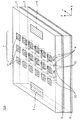
図1は、第1の実施形態に係るアンテナ装置100の構成を示す斜視図である。図2は、図1のアンテナ装置100における第1の導体層の構成を示す上面図である。図3は、図1のアンテナ装置100における第2の導体層の構成を示す上面図である。図4は、図1のアンテナ装置100における第3の導体層の構成を示す上面図である。図5は、図2のA−A’線におけるアンテナ装置100の構成を示す断面図である。
First Embodiment
FIG. 1 is a perspective view showing the configuration of the
アンテナ装置100は、誘電体層1及び2と、誘電体層1の上面に形成された第1の導体層と、誘電体層1及び2間に形成された第2の導体層と、誘電体層2の下面に形成された第3の導体層とを有する基板を備える。言い換えると、第1及び第2の導体層は誘電体層1の両面に形成され、第3の導体層は、第1の導体層とは逆の側に第2の導体層から所定距離を有して、第2の導体層に平行に形成される。アンテナ装置100は、さらに、第1の導体層に配置された第1のアンテナ素子3(受信アンテナ)及び第2のアンテナ素子4(送信アンテナ)と、第2の導体層に配置された第1の接地導体5と、第3の導体層に配置された第2の接地導体6と、基板上においてアンテナ素子3及び4間に配置されたEBG構造部7とを備える。例えば、アンテナ素子3は受信アンテナとして動作し、アンテナ素子4は送信アンテナとして動作してもよい。
誘電体層1及び2は、例えば、ポリフェニレンエーテル又はポリテトラフルオロエチレンなどであってもよい。
The
EBG構造部7は、第1の導体層に配置され、接地導体5との電磁的結合を有する複数の第1のパッチ導体11を含む第1のEBG部分と、第2の導体層に配置され、接地導体5との電磁的結合を有する複数の第2のパッチ導体13を含む第2のEBG部分とを含む。複数のパッチ導体13は接地導体6との電磁的結合も有する。
The
図1の例では、各パッチ導体11及び13は正方形形状を有する。しかしながら、各パッチ導体11及び13は、正方形に限らず、三角形、六角形、長方形、などの任意の形状であってもよい。
In the example of FIG. 1, each
図2に示すように、複数のパッチ導体11は、第1の導体層において、アンテナ素子3及び4を結ぶ線分に交差するように延在する複数の第1の列(図2のY方向の列)に沿って配置される。第1のEBG部分は、基板の誘電体層1をそれぞれ貫通し、複数のパッチ導体11を接地導体5にそれぞれ接続する複数のビア導体12をさらに備える。このように、第1のEBG部分はマッシュルーム型のEBG構造部である。本明細書では、第1のEBG部分のパッチ導体11及びビア導体12の各列を、EBGセグメント7−1a,7−1b,7−1cという。
As shown in FIG. 2, the plurality of
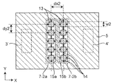
図3に示すように、複数のパッチ導体13は、第2の導体層において、アンテナ素子3に対向する領域3’及びアンテナ素子4に対向する領域4’を結ぶ線分に交差するように延在する複数の第2の列に沿って配置される。第2のEBG部分は、複数のパッチ導体13にそれぞれ接続された複数のスタブ導体14をさらに備える。複数のスタブ導体14は、例えば、図3のX方向又はY方向に沿って配置される。複数のスタブ導体14は、接地導体5に短絡されていてもよく、接地導体5に短絡されることなく開放端を有してもよい。第2の導体層には、パッチ導体13及びスタブ導体14を内部に形成するためのスロット15a及び15bが設けられる。このように、第2のEBG部分はビアレスEBG構造部である。本明細書では、第2のEBG部分のパッチ導体13及びスタブ導体14の各列を、EBGセグメント7−2a,7−2bという。
As shown in FIG. 3, the plurality of
EBGセグメント7−1a,7−1b,7−1c(特に、各ビア導体12が接地導体5に接続される位置)と、EBGセグメント7−2a,7−2bとは、上から見たときに互い違いになるように配置される。
EBG segments 7-1a, 7-1b, 7-1c (in particular, positions where each via
EBGセグメント7−1a,7−1b,7−1cは、例えば、アンテナ素子3及び4間のアイソレーションを高くしようとする周波数帯域であるアイソレーション帯域の中心周波数に対応する波長にわたって互いに離隔して互いに平行に設けられる。EBGセグメント7−2a,7−2bもまた、例えば、アイソレーション帯域の中心周波数に対応する波長にわたって互いに離隔して互いに平行に設けられる。EBGセグメント7−1a,7−1b,7−1c間の距離はこれに限らず、EBGセグメント7−1a,7−1b,7−1cは、アイソレーション帯域の中心周波数に対応する波長の0.8〜1.2倍のうちの1つの長さにわたって互いに離隔して互いに平行に設けられてもよい。同様に、EBGセグメント7−2a,7−2b間の距離はこれに限らず、EBGセグメント7−2a,7−2bは、アイソレーション帯域の中心周波数に対応する波長の0.8〜1.2倍のうちの1つの長さにわたって互いに離隔して互いに平行に設けられてもよい。
The EBG segments 7-1a, 7-1b, 7-1c are, for example, separated from one another over the wavelength corresponding to the center frequency of the isolation band, which is a frequency band in which the isolation between the
図2において、「w1」はパッチ導体11の辺の長さを示し、「dx1」はX方向に互いに隣接するパッチ導体11の中心間の距離(又はEBGセグメント7−1a,7−1b,7−1c間の距離)を示し、「dy1」はY方向に互いに隣接するパッチ導体11の中心間の距離を示す。図3において、「w2」はパッチ導体13の辺の長さを示し、「dx2」はX方向に互いに隣接するパッチ導体13の中心間の距離(又はEBGセグメント7−2a,7−2b間の距離)を示し、「dy2」はY方向に互いに隣接するパッチ導体13の中心間の距離を示す。図5において、「dz1」はパッチ導体11と接地導体5との間の距離(又はビア導体12の長さ)を示し、「dz2」は接地導体5,6間の距離を示す。また、ビア導体12は直径φを有する。
In FIG. 2, “w1” indicates the side length of the
第1のEBG部分は基板の表面に露出し、第2のEBG部分は基板の内部に設けられるので、それらの特性は互いに異なる。第1のEBG部分及び第2のEBG部分に必要な特性に応じて、パッチ導体11,13の個数、辺の長さw1,w2、及び距離dy1,dy2は互いに異なっていてもよい。
Since the first EBG portion is exposed on the surface of the substrate and the second EBG portion is provided inside the substrate, their properties are different from each other. The number of
図1のアンテナ装置100は、例えばミリ波帯域で動作する。しかしながら、図1のアンテナ装置100は、ミリ波帯域に限らず、アイソレーション帯域を生じるようにEBG構造部7を設計可能な任意の周波数で動作してもよい。
The
複数のスタブ導体14は、所望のアイソレーション特性に応じて、接地導体5に短絡されてもよい。
The plurality of
第2のEBG部分と接地導体5との電磁的結合を変化させることにより、第2のEBG部分のアイソレーション帯域を低域側もしくは高域側に拡張させることができる。
By changing the electromagnetic coupling between the second EBG portion and the
図1のアンテナ装置100によれば、周波数調整のために余分な部品を必要とせず、アンテナ装置を大型化せず、広い周波数帯域幅にわたって高いアイソレーションを確保することができる。
According to the
図6は、第1の実施形態の変形例に係るアンテナ装置101の構成を示す斜視図である。所望のアイソレーション特性によっては、図1のアンテナ装置100の接地導体6及び誘電体層2を省略してもよい。
FIG. 6 is a perspective view showing the configuration of an
次に、図7〜図14を参照して、図1のアンテナ装置100の動作について説明する。
The operation of the
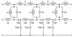
図7は、図1のアンテナ装置100のEBG構造部7の詳細構成を示す拡大図である。図8は、図7のEBG構造部7の等価回路図である。図7において、「L」はパッチ導体11のインダクタンスを示し、「Ls」はビア導体12のインダクタンスを示し、「Lg」は、パッチ導体11に対向していない部分(EBG構造部7の外部)における接地導体5のインダクタンスを示し、「Lgx」は、パッチ導体13及びスタブ導体14のインダクタンスを示す。さらに、「C」は互いに隣接するパッチ導体11間の容量を示し、「Cs」はパッチ導体11と接地導体5との間の容量を示す。また「Cgx」は、パッチ導体13及びスタブ導体14と接地導体5との間の容量を示し、「Cgy」は、パッチ導体13及びスタブ導体14と接地導体6との間の容量を示す。
FIG. 7 is an enlarged view showing the detailed configuration of the
EBG構造部7の反共振周波数は、EBG構造部7を構成する各部分の容量及びインダクタンスによって決まる。パッチ導体11のインダクタンスLは、パッチ導体11の寸法(例えば、辺の長さw1)に依存する。パッチ導体11間の容量Cは、パッチ導体11の中心間の距離dx1,dy1に依存する。パッチ導体11と接地導体5との間の容量Csは、パッチ導体11の面積と、パッチ導体11と接地導体5との間の距離dz1とに依存する。ビア導体12のインダクタンスLsは、ビア導体の直径φ及び長さdz1に依存する。ビア導体の直径φ及び長さdz1は、プロセス上の制約を受けるので、実質的に固定値である。従って、プロセス上の制約を考慮してアンテナ設計時に変更可能なパラメータは、パッチ導体11の辺の長さw1及びパッチ導体11の中心間の距離dx1,dy1のみである。
The antiresonance frequency of the
EBG構造部のアイソレーション効果を高める平易な方法として、EBG構造部を多段化することが知られている。多段EBG構造部は、例えば、複数の基板を備え、これらの基板を貫通するように複数のビア導体が設けられる。しかしながら、各基板においてビア導体を設けた部分には他の部品及び配線を設けることができないので、アンテナ装置の寸法が増大し、従ってコストも増大する。このため、EBG構造部の余分な多段化をすることなく、EBG構造部のアイソレーション効果を高めることが望まれる。 As a simple method for enhancing the isolation effect of the EBG structure, it is known to multistage the EBG structure. The multistage EBG structure includes, for example, a plurality of substrates, and a plurality of via conductors are provided to penetrate the substrates. However, since it is not possible to provide other parts and wiring in the portion provided with the via conductor in each substrate, the size of the antenna device is increased and hence the cost is also increased. For this reason, it is desirable to enhance the isolation effect of the EBG structure without extra multistage formation of the EBG structure.
次に、図9〜図14を参照して、図1のアンテナ装置100のシミュレーション結果について説明する。
Next, with reference to FIGS. 9-14, the simulation result of the
図9は、第1の比較例に係るアンテナ装置200の構成を示す斜視図である。図9のアンテナ装置200は、図1のアンテナ装置100からEBG構造部7を除去した構成を有する。
FIG. 9 is a perspective view showing the configuration of the
図10は、第2の比較例に係るアンテナ装置201の構成を示す斜視図である。図10のアンテナ装置201は、図1のアンテナ装置100から第2のEBG部分(パッチ導体13、スタブ導体14、及びスロット15a,15b)を除去した構成を有する。
FIG. 10 is a perspective view showing a configuration of an
以下のパラメータを設定してシミュレーションを行った。誘電体層1の厚さはdz1=0.254mmであり、誘電体層2の厚さはdz2=0.3mmであった。誘電体層1,2の比誘電率はεr=3.0であり、誘電正接はtanδ=0.0058であった。アンテナ素子3及び4は、0.91mm×0.91mmの正方形のパッチアンテナであった。アンテナ素子3及び4は、X方向に13.2mmの距離(中心間の距離)を有して配置された。アイソレーション帯域の中心周波数は79GHzであった。
The simulation was performed with the following parameters set. The thickness of the
図11は、比較例に係るアンテナ装置200及び201における周波数特性のグラフである。比較例に係るアンテナ装置200は、図9の構成(EBG構造部なし)を有する。比較例に係るアンテナ装置201は、図10の構成(パッチ導体11及びスタブ導体12のみを備えるEBG構造部)を有する。比較例に係るアンテナ装置201のEGB構造部は、X方向に3個かつY方向に85個のパッチ導体11を含み、アンテナ素子3及び4の中間に配置された。パッチ導体11の辺の長さをw1=0.61mmに固定し、Y方向に互いに隣接するパッチ導体11の中心間の距離をdy1=0.71mmに固定した。ビア導体12の直径はφ=0.25mmであり、長さはdz1=0.254mmであった。比較例に係るアンテナ装置201では、EBGセグメント7−1a,7−1b,7−1c間の距離dx1を変化させ、距離dx1は、アイソレーション帯域の中心周波数79GHzに対応する波長λ(2.2mm)又は約λ/4(0.7mm)に設定された。距離dx1を最適化することにより、容量C及びインダクタンスLgが劇的に減少し、アンテナ素子3及び4の相互インピーダンスが高くなる。図11によれば、距離dx1を最適化することにより(dx1=λ)、高いアイソレーションを達成できることがわかる。
FIG. 11 is a graph of frequency characteristics of the
図11によれば、比較例に係るアンテナ装置201において距離dx1=λに設定したとき、アイソレーション帯域の中心周波数79GHzを含む非常に狭いアイソレーション帯域においてのみ高いアイソレーションが達成されている。従って、高いアイソレーションを達成しながら、アイソレーション帯域を広帯域化することが望まれる。
According to FIG. 11, when the distance dx1 = λ is set in the
図12は、実施例に係るアンテナ装置100及び比較例に係るアンテナ装置201における周波数特性のグラフである。比較例に係るアンテナ装置201は、図10の構成(パッチ導体11及びビア導体12のみを備えるEBG構造部)を有し、距離dx1は、アイソレーション帯域の中心周波数79GHzに対応する波長λ(2.2mm)に設定された。実施例に係るアンテナ装置100は、図1の構成を有し、第1のEBG部分(パッチ導体11及びビア導体12)及び第2のEBG部分(パッチ導体13及びスタブ導体14)を含むEBG構造部7は、アンテナ素子3及び4の中間に配置された。実施例に係るアンテナ装置100の第1のEBG部分は、比較例に係るアンテナ装置201のEBG構造部と同様に構成された。実施例に係るアンテナ装置100の第2のEBG部分は、X方向に2個かつY方向に42個のパッチ導体13を配置した。パッチ導体13の辺の長さをw2=1.05mmに固定し、Y方向に互いに隣接するパッチ導体13の中心間の距離をdy2=1.15mmに固定した。パッチ導体13から接地導体5までの距離は0.2mmであった。スタブ導体14の長さを0.1mmとし、スタブ導体14は接地導体5に短絡されることなく開放端を有し、スタブ導体14の開放端から接地導体5までの距離を0.1mmとした。実施例に係るアンテナ装置100では、距離dx1,dx2は、アイソレーション帯域の中心周波数79GHzに対応する波長λ(2.2mm)に設定された。図12によれば、比較例に係るアンテナ装置201に第2のEBG部分(パッチ導体13、スタブ導体14、及びスロット15a,15b)を追加することにより、アイソレーション帯域が広帯域化されていることがわかる。図12によれば、特に、アイソレーション帯域の中心周波数79GHzよりも低域側において、アイソレーションが向上している。
FIG. 12 is a graph of frequency characteristics in the
EBG構造部7は、磁気壁として動作し、アンテナ素子3、4間における表面波の伝搬を抑制する。第2のEBG部分(パッチ導体13、スタブ導体14、及びスロット15a,15b)は、第1のEBG部分のみを備える比較例に係るアンテナ装置201よりも、アイソレーション帯域を低域側又は広域側に広げるように構成することができる。第2のEBG部分を備えることにより、比較例に係るアンテナ装置201よりも、アンテナ素子3,4間のクロストークを確実に低減することができる。
The
図1のアンテナ装置100によれば、第1のEBG部分及び第2のEBG部分の両方を備え、距離dx1,dx2をアイソレーション帯域の中心周波数79GHzに対応する波長λに設定することにより、比較例に係るアンテナ装置200及び201よりもアイソレーション帯域を劇的に広帯域化することが可能となる。
According to the
距離dx1,dx2はアイソレーション帯域の中心周波数79GHzに対応する波長λに限らず、1λの近傍の長さであればよい。図13及び図14を参照して、距離dx1及びdx2の周波数特性への影響についてさらに説明する。 The distances dx1 and dx2 are not limited to the wavelength λ corresponding to the center frequency 79 GHz of the isolation band, and may be a length near 1λ. The influence of the distances dx1 and dx2 on the frequency characteristics will be further described with reference to FIGS. 13 and 14.
図13は、比較例に係るアンテナ装置201における周波数特性のグラフである。図14は、比較例に係るアンテナ装置201における周波数特性のグラフである。シミュレーションの簡単化のために、図1のアンテナ装置100ではなく、図10のアンテナ装置201を用いた。EBGセグメント7−1a,7−1b,7−1c間の距離dx1を変化させ、距離dx1は、0.8λ、0.9λ、1λ、1.1λ、又は1.2λに設定された。図13及び図14によれば、距離dx1が1λの近傍の0.8λ〜1.2λの長さであっても、高いアイソレーションを確保できることがわかる。図13及び図14の結果は、図1のアンテナ装置100にも同様にあてはまる。
FIG. 13 is a graph of frequency characteristics in the
第2の実施形態.
図15は、第2の実施形態に係る無線通信装置の構成を示すブロック図である。図15の無線通信装置は、図1を参照して説明したアンテナ装置100と、無線通信回路111と、信号処理回路112とを備える。無線通信回路111は、信号処理回路112から送られたベースバンド信号を変調した無線信号をアンテナ装置100から放射し、アンテナ装置100で受信された無線信号を復調したベースバンド信号を信号処理回路112に送る。
Second embodiment.
FIG. 15 is a block diagram showing the configuration of the wireless communication apparatus according to the second embodiment. The wireless communication apparatus of FIG. 15 includes the
第3の実施形態.
図16は、第3の実施形態に係るレーダ装置の構成を示すブロック図である。図16の無線通信装置は、図1を参照して説明したアンテナ装置100と、レーダ送受信回路121と、信号処理回路122と、表示装置123とを備える。レーダ送受信回路121は、信号処理回路122の制御下でレーダ波をアンテナ装置100から放射し、目標物で反射されてアンテナ装置100に入射したレーダ波を受信する。信号処理回路122は、レーダ波の伝搬時間、周波数変化、などに基づいて、アンテナ装置100から目標物までの距離、速度、などを決定し、その結果を表示装置123に表示する。
Third embodiment.
FIG. 16 is a block diagram showing the configuration of a radar system according to the third embodiment. The wireless communication apparatus of FIG. 16 includes the
各実施形態のアンテナ装置100によれば、アイソレーションを向上させ、且つ、アイソレーション帯域を劇的に広帯域化することが可能となる。
According to the
本開示の態様に係るアンテナ装置、無線通信装置、及びレーダ装置は、以下の構成を備えたことを特徴とする。 An antenna device, a wireless communication device, and a radar device according to an aspect of the present disclosure are characterized by having the following configurations.
第1の態様に係るアンテナ装置は、
誘電体層と、前記誘電体層の両面に形成された第1及び第2の導体層とを有する基板と、
前記第1の導体層に配置された第1及び第2のアンテナ素子と、
前記第2の導体層に配置された第1の接地導体と、
前記基板上において前記第1及び第2のアンテナ素子の間に配置されたEBG(Electromagnetic Band Gap)構造部とを備えるアンテナ装置において、
前記EBG構造部は、
前記第1の導体層に配置され、前記第1の接地導体との電磁的結合を有する複数の第1のパッチ導体を含む第1のEBG部分と、
前記第2の導体層に配置され、前記第1の接地導体との電磁的結合を有する複数の第2のパッチ導体を含む第2のEBG部分とを含む。
The antenna device according to the first aspect is
A substrate having a dielectric layer and first and second conductor layers formed on both sides of the dielectric layer;
First and second antenna elements disposed in the first conductor layer;
A first ground conductor disposed in the second conductor layer;
An antenna device comprising: an electromagnetic band gap (EBG) structure portion disposed between the first and second antenna elements on the substrate;
The EBG structure is
A first EBG portion including a plurality of first patch conductors disposed in the first conductor layer and having an electromagnetic coupling with the first ground conductor;
And a second EBG portion including a plurality of second patch conductors disposed in the second conductor layer and having an electromagnetic coupling with the first ground conductor.
第2の態様に係るアンテナ装置は、第1の態様に係るアンテナ装置において、
前記複数の第1のパッチ導体は、前記第1の導体層において、前記第1及び第2のアンテナ素子を結ぶ線分に交差するように延在する複数の第1の列に沿って配置され、
前記第1のEBG部分は、前記基板をそれぞれ貫通し、前記複数の第1のパッチ導体を前記第1の接地導体にそれぞれ接続する複数のビア導体をさらに備える。
An antenna device according to a second aspect is the antenna device according to the first aspect, wherein
The plurality of first patch conductors are arranged in the first conductor layer along a plurality of first columns extending to intersect line segments connecting the first and second antenna elements. ,
The first EBG portion further comprises a plurality of via conductors respectively penetrating the substrate and connecting the plurality of first patch conductors to the first ground conductor.
第3の態様に係るアンテナ装置は、第2の態様に係るアンテナ装置において、
前記複数の第2のパッチ導体は、前記第2の導体層において、前記第1のアンテナ素子に対向する領域及び前記第2のアンテナ素子に対向する領域を結ぶ線分に交差するように延在する複数の第2の列に沿って配置され、
前記第2のEBG部分は、前記複数の第2のパッチ導体にそれぞれ接続された複数のスタブ導体をさらに備える。
An antenna device according to a third aspect is the antenna device according to the second aspect, wherein
The plurality of second patch conductors extend so as to intersect a line segment connecting a region facing the first antenna element and a region facing the second antenna element in the second conductor layer. Are arranged along a plurality of second columns,
The second EBG portion further comprises a plurality of stub conductors respectively connected to the plurality of second patch conductors.
第4の態様に係るアンテナ装置は、第3の態様に係るアンテナ装置において、
前記複数の第1の列は、前記第1及び第2のアンテナ素子間のアイソレーションを高くしようとする周波数帯域であるアイソレーション帯域の中心周波数に対応する波長の0.8〜1.2倍のうちの1つの長さにわたって互いに離隔して互いに平行に設けられ、
前記複数の第2の列は、前記アイソレーション帯域の中心周波数に対応する波長の0.8〜1.2倍のうちの1つの長さにわたって互いに離隔して互いに平行に設けられる。
An antenna device according to a fourth aspect is the antenna device according to the third aspect, wherein
The plurality of first columns are 0.8 to 1.2 times the wavelength corresponding to the center frequency of the isolation band which is a frequency band in which the isolation between the first and second antenna elements is to be increased. Provided parallel to one another, spaced apart over a length of one of
The plurality of second columns are spaced apart and parallel to one another over a length of one of 0.8 to 1.2 times the wavelength corresponding to the center frequency of the isolation band.
第5の態様に係るアンテナ装置は、第1〜第4のうちの1つの態様に係るアンテナ装置において、
前記基板は、前記第1の導体層とは逆の側に前記第2の導体層から所定距離を有して、前記第2の導体層に平行に形成された第3の導体層をさらに備え、
前記アンテナ装置は、前記第3の導体層に配置された第2の接地導体をさらに備える。
An antenna device according to a fifth aspect is the antenna device according to one of the first to fourth aspects, wherein
The substrate further includes a third conductor layer formed in parallel with the second conductor layer at a predetermined distance from the second conductor layer on the side opposite to the first conductor layer. ,
The antenna device further includes a second ground conductor disposed in the third conductor layer.
第6の態様に係る無線通信装置は、
第1〜第5のうちの1つの態様に係るアンテナ装置と、
無線通信回路とを備える。
The wireless communication apparatus according to the sixth aspect is
An antenna device according to one of the first to fifth aspects;
And a wireless communication circuit.
第7の態様に係るレーダ装置は、
第1〜第5のうちの1つの態様に係るアンテナ装置と、
レーダ送受信回路とを備える。
The radar device according to the seventh aspect is
An antenna device according to one of the first to fifth aspects;
And a radar transmission / reception circuit.
本開示の態様に係るアンテナ装置は、ミリ波帯で動作するアンテナ装置、無線通信装置、及びレーダ装置として利用可能である。 An antenna device according to an aspect of the present disclosure can be used as an antenna device operating in a millimeter wave band, a wireless communication device, and a radar device.
1,2…誘電体層、
3…アンテナ素子、
4…アンテナ素子、
5,6…接地導体、
7…EBG構造部、
7−1a,7−1b,7−1c,7−2a,7−2b…EBGセグメント、
11…パッチ導体、
12…ビア導体、
13…パッチ導体、
14…スタブ導体、
15a,15b…スロット、
100,101…アンテナ装置、
111…無線通信回路、
112…信号処理回路、
121…レーダ送受信回路、
122…信号処理回路、
123…表示装置。
1, 2 ... dielectric layer,
3 ... antenna element,
4 ... antenna element,
5, 6 ... Ground conductor,
7 ... EBG structure part,
7-1a, 7-1b, 7-1c, 7-2a, 7-2b ... EBG segments,
11 ... patch conductor,
12 ... via conductor,
13 ... patch conductor,
14: Stub conductor,
15a, 15b ... slots,
100, 101 ... antenna device,
111 ... wireless communication circuit,
112: Signal processing circuit,
121: Radar transmission / reception circuit,
122: Signal processing circuit,
123 ... display device.
Claims (7)
前記第1の導体層に配置された第1及び第2のアンテナ素子と、
前記第2の導体層に配置された第1の接地導体と、
前記基板上において前記第1及び第2のアンテナ素子の間に配置されたEBG(Electromagnetic Band Gap)構造部と、を備えるアンテナ装置において、
前記EBG構造部は、
前記第1の導体層に配置され、前記第1の接地導体との電磁的結合を有する複数の第1のパッチ導体を含む第1のEBG部分と、
前記第2の導体層に配置され、前記第1の接地導体との電磁的結合を有する複数の第2のパッチ導体を含む第2のEBG部分と、を含み、
前記複数の第1のパッチ導体は、前記第1の導体層において、前記第1及び第2のアンテナ素子を結ぶ線分に交差するように延在する複数の第1の列に沿って配置され、
前記第1のEBG部分は、前記基板をそれぞれ貫通し、前記複数の第1のパッチ導体を前記第1の接地導体にそれぞれ接続する複数のビア導体をさらに備え、
前記複数の第2のパッチ導体は、前記第2の導体層において、前記第1のアンテナ素子に対向する領域及び前記第2のアンテナ素子に対向する領域を結ぶ線分に交差するように延在する複数の第2の列に沿って配置され、
前記第2のEBG部分は、前記複数の第2のパッチ導体にそれぞれ接続された複数のスタブ導体をさらに備える、
アンテナ装置。 A substrate having a dielectric layer and first and second conductor layers formed on both sides of the dielectric layer;
First and second antenna elements disposed in the first conductor layer;
A first ground conductor disposed in the second conductor layer;
An antenna device comprising: an EBG (Electromagnetic Band Gap) structure portion disposed between the first and second antenna elements on the substrate;
The EBG structure is
A first EBG portion including a plurality of first patch conductors disposed in the first conductor layer and having an electromagnetic coupling with the first ground conductor;
A second EBG portion disposed in the second conductor layer and including a plurality of second patch conductors having electromagnetic coupling with the first ground conductor;
The plurality of first patch conductors are arranged in the first conductor layer along a plurality of first columns extending to intersect line segments connecting the first and second antenna elements. ,
The first EBG portion further comprises a plurality of via conductors respectively penetrating the substrate and connecting the plurality of first patch conductors to the first ground conductor,
The plurality of second patch conductors extend so as to intersect a line segment connecting a region facing the first antenna element and a region facing the second antenna element in the second conductor layer. Are arranged along a plurality of second columns,
The second EBG portion further comprises a plurality of stub conductors respectively connected to the plurality of second patch conductors ,
Antenna equipment.
前記複数の第2の列は、前記アイソレーション帯域の中心周波数に対応する波長の0.8〜1.2倍のうちの1つの長さにわたって互いに離隔して互いに平行に設けられる、
請求項1に記載のアンテナ装置。 The plurality of first columns are 0.8 to 1.2 times the wavelength corresponding to the center frequency of the isolation band which is a frequency band in which the isolation between the first and second antenna elements is to be increased. Provided parallel to one another, spaced apart over a length of one of
The plurality of second columns are provided parallel to each other, spaced apart from each other over a length of one of 0.8 to 1.2 times a wavelength corresponding to a center frequency of the isolation band.
The antenna device according to claim 1 .
前記第1の導体層に配置された第1及び第2のアンテナ素子と、
前記第2の導体層に配置された第1の接地導体と、
前記基板上において前記第1及び第2のアンテナ素子の間に配置されたEBG(Electromagnetic Band Gap)構造部と、を備えるアンテナ装置において、
前記EBG構造部は、
前記第1の導体層に配置され、前記第1の接地導体との電磁的結合を有する複数の第1のパッチ導体を含む第1のEBG部分と、
前記第2の導体層に配置され、前記第1の接地導体との電磁的結合を有する複数の第2のパッチ導体を含む第2のEBG部分と、を含み、
前記基板は、前記第1の導体層とは逆の側に前記第2の導体層から所定距離を有して、前記第2の導体層に平行に形成された第3の導体層をさらに備え、
前記アンテナ装置は、前記第3の導体層に配置された第2の接地導体をさらに備える、
アンテナ装置。 A substrate having a dielectric layer and first and second conductor layers formed on both sides of the dielectric layer;
First and second antenna elements disposed in the first conductor layer;
A first ground conductor disposed in the second conductor layer;
An antenna device comprising: an EBG (Electromagnetic Band Gap) structure portion disposed between the first and second antenna elements on the substrate;
The EBG structure is
A first EBG portion including a plurality of first patch conductors disposed in the first conductor layer and having an electromagnetic coupling with the first ground conductor;
A second EBG portion disposed in the second conductor layer and including a plurality of second patch conductors having electromagnetic coupling with the first ground conductor;
The substrate further includes a third conductor layer formed in parallel with the second conductor layer at a predetermined distance from the second conductor layer on the side opposite to the first conductor layer. ,
The antenna device further comprises a second ground conductor disposed in the third conductor layer ,
Antenna equipment.
前記第1の導体層に配置された第1及び第2のアンテナ素子と、
前記第2の導体層に配置された第1の接地導体と、
前記基板上において前記第1及び第2のアンテナ素子の間に配置されたEBG(Electromagnetic Band Gap)構造部と、を備えるアンテナ装置において、
前記EBG構造部は、
前記第1の導体層に配置され、前記第1の接地導体との電磁的結合を有する複数の第1のパッチ導体を含む第1のEBG部分と、
前記第2の導体層に配置され、前記第1の接地導体との電磁的結合を有する複数の第2のパッチ導体を含む第2のEBG部分と、を含み、
前記複数の第1のパッチ導体は、前記第1の導体層において、前記第1及び第2のアンテナ素子を結ぶ線分に交差するように延在する複数の第1の列に沿って配置され、
前記複数の第2のパッチ導体は、前記第2の導体層において、前記第1のアンテナ素子に対向する領域及び前記第2のアンテナ素子に対向する領域を結ぶ線分に交差するように延在する複数の第2の列に沿って配置され、
前記複数の第1の列と前記複数の第2の列とは、前記誘電体層の両面に対する垂線上の点から見たときに互い違いになるように配置される、
アンテナ装置。 A substrate having a dielectric layer and first and second conductor layers formed on both sides of the dielectric layer;
First and second antenna elements disposed in the first conductor layer;
A first ground conductor disposed in the second conductor layer;
An antenna device comprising: an EBG (Electromagnetic Band Gap) structure portion disposed between the first and second antenna elements on the substrate;
The EBG structure is
A first EBG portion including a plurality of first patch conductors disposed in the first conductor layer and having an electromagnetic coupling with the first ground conductor;
A second EBG portion disposed in the second conductor layer and including a plurality of second patch conductors having electromagnetic coupling with the first ground conductor;
The plurality of first patch conductors are arranged in the first conductor layer along a plurality of first columns extending to intersect line segments connecting the first and second antenna elements. ,
The plurality of second patch conductors extend so as to intersect a line segment connecting a region facing the first antenna element and a region facing the second antenna element in the second conductor layer. Are arranged along a plurality of second columns,
The plurality of first rows and the plurality of second rows are arranged to be staggered when viewed from a point perpendicular to both sides of the dielectric layer ,
Antenna equipment.
前記第1の導体層に配置された第1及び第2のアンテナ素子と、
前記第2の導体層に配置された第1の接地導体と、
前記基板上において前記第1及び第2のアンテナ素子の間に配置されたEBG(Electromagnetic Band Gap)構造部と、を備えるアンテナ装置において、
前記EBG構造部は、
前記第1の導体層に配置され、前記第1の接地導体との電磁的結合を有する複数の第1のパッチ導体を含む第1のEBG部分と、
前記第2の導体層に配置され、前記第1の接地導体との電磁的結合を有する複数の第2のパッチ導体を含む第2のEBG部分と、を含み、
前記複数の第2のパッチ導体は、前記第2の導体層において、前記第1のアンテナ素子に対向する領域及び前記第2のアンテナ素子に対向する領域を結ぶ線分に交差するように延在する複数の第2の列に沿って配置され、
前記第2のEBG部分は、前記複数の第2のパッチ導体と前記第1の接地導体とを接続する複数のスタブ導体をさらに備える、
アンテナ装置。 A substrate having a dielectric layer and first and second conductor layers formed on both sides of the dielectric layer;
First and second antenna elements disposed in the first conductor layer;
A first ground conductor disposed in the second conductor layer;
An antenna device comprising: an EBG (Electromagnetic Band Gap) structure portion disposed between the first and second antenna elements on the substrate;
The EBG structure is
A first EBG portion including a plurality of first patch conductors disposed in the first conductor layer and having an electromagnetic coupling with the first ground conductor;
A second EBG portion disposed in the second conductor layer and including a plurality of second patch conductors having electromagnetic coupling with the first ground conductor;
The plurality of second patch conductors extend so as to intersect a line segment connecting a region facing the first antenna element and a region facing the second antenna element in the second conductor layer. Are arranged along a plurality of second columns,
The second EBG portion further comprises a plurality of stub conductors connecting the plurality of second patch conductors and the first ground conductor .
Antenna equipment.
無線通信回路と、を備える、
無線通信装置。 The antenna device according to any one of claims 1 to 5 ;
It includes a wireless communication circuit, a,
Wireless communication device.
レーダ送受信回路と、を備える、
レーダ装置。 The antenna device according to any one of claims 1 to 5 ;
It includes a radar transceiver circuit, a,
Radar equipment.
Priority Applications (4)
| Application Number | Priority Date | Filing Date | Title |
|---|---|---|---|
| JP2015102842A JP6512402B2 (en) | 2015-05-20 | 2015-05-20 | Antenna device, wireless communication device, and radar device |
| CN201610128515.9A CN106169645A (en) | 2015-05-20 | 2016-03-08 | Antenna assembly, radio communication device and radar installations |
| EP16166767.0A EP3096402B1 (en) | 2015-05-20 | 2016-04-25 | Antenna device, wireless communication apparatus, and radar apparatus |
| US15/140,275 US10014572B2 (en) | 2015-05-20 | 2016-04-27 | Antenna device, wireless communication apparatus, and radar apparatus |
Applications Claiming Priority (1)
| Application Number | Priority Date | Filing Date | Title |
|---|---|---|---|
| JP2015102842A JP6512402B2 (en) | 2015-05-20 | 2015-05-20 | Antenna device, wireless communication device, and radar device |
Publications (3)
| Publication Number | Publication Date |
|---|---|
| JP2016220029A JP2016220029A (en) | 2016-12-22 |
| JP2016220029A5 JP2016220029A5 (en) | 2018-02-15 |
| JP6512402B2 true JP6512402B2 (en) | 2019-05-15 |
Family
ID=55808482
Family Applications (1)
| Application Number | Title | Priority Date | Filing Date |
|---|---|---|---|
| JP2015102842A Expired - Fee Related JP6512402B2 (en) | 2015-05-20 | 2015-05-20 | Antenna device, wireless communication device, and radar device |
Country Status (4)
| Country | Link |
|---|---|
| US (1) | US10014572B2 (en) |
| EP (1) | EP3096402B1 (en) |
| JP (1) | JP6512402B2 (en) |
| CN (1) | CN106169645A (en) |
Families Citing this family (50)
| Publication number | Priority date | Publication date | Assignee | Title |
|---|---|---|---|---|
| US9680202B2 (en) * | 2013-06-05 | 2017-06-13 | Apple Inc. | Electronic devices with antenna windows on opposing housing surfaces |
| WO2018119944A1 (en) * | 2016-12-29 | 2018-07-05 | 深圳天珑无线科技有限公司 | Multi-input multi-output antenna system and mobile terminal |
| JP2018129623A (en) * | 2017-02-07 | 2018-08-16 | パナソニック株式会社 | Module, radio communication device, and radar device |
| JP6822926B2 (en) * | 2017-04-24 | 2021-01-27 | 株式会社Soken | Antenna device |
| NL2020017B1 (en) * | 2017-04-25 | 2018-11-05 | The Antenna Company International N V | EBG structure, EBG component, and antenna device |
| USD856313S1 (en) | 2017-04-25 | 2019-08-13 | The Antenna Company International N.V. | Dual port antenna |
| WO2018199753A1 (en) * | 2017-04-25 | 2018-11-01 | The Antenna Company International N.V. | Ebg structure, ebg component, and antenna device |
| EP3616255B8 (en) * | 2017-04-25 | 2023-10-25 | The Antenna Company International N.V. | Ebg structure, ebg component, and antenna device |
| USD883962S1 (en) | 2017-04-25 | 2020-05-12 | The Antenna Company International N.V. | Dual port antenna assembly |
| KR102348241B1 (en) * | 2017-05-30 | 2022-01-10 | 삼성전자주식회사 | Antenna array and electronic device for including the same |
| WO2018235593A1 (en) | 2017-06-23 | 2018-12-27 | 株式会社ソシオネクスト | Antenna device |
| WO2019066176A1 (en) | 2017-09-27 | 2019-04-04 | 엘지전자 주식회사 | Electronic device |
| KR101986170B1 (en) * | 2017-09-27 | 2019-06-07 | 엘지전자 주식회사 | Electronic device |
| US10886622B1 (en) * | 2017-10-05 | 2021-01-05 | Hrl Laboratories, Llc | Tunable antenna isolators |
| JP6954376B2 (en) * | 2017-12-28 | 2021-10-27 | 株式会社村田製作所 | Antenna array and antenna module |
| KR20190083588A (en) * | 2018-01-04 | 2019-07-12 | 삼성전자주식회사 | Electromagnetic band-gap sturcture and electronic device with the same |
| US11233310B2 (en) * | 2018-01-29 | 2022-01-25 | The Boeing Company | Low-profile conformal antenna |
| CN110120582B (en) * | 2018-02-06 | 2022-03-11 | 德尔福技术有限公司 | Antenna device |
| US11217904B2 (en) | 2018-02-06 | 2022-01-04 | Aptiv Technologies Limited | Wide angle coverage antenna with parasitic elements |
| WO2019193793A1 (en) * | 2018-04-06 | 2019-10-10 | パナソニックIpマネジメント株式会社 | Antenna device and electronic device |
| US10965030B2 (en) * | 2018-04-30 | 2021-03-30 | Samsung Electro-Mechanics Co., Ltd. | Antenna apparatus |
| CN108767449B (en) * | 2018-06-15 | 2020-12-15 | 京信通信技术(广州)有限公司 | Multi-system fusion antenna based on AMC structure |
| JP7064600B2 (en) * | 2018-08-24 | 2022-05-10 | 京セラ株式会社 | Structures, antennas, wireless communication modules, and wireless communication equipment |
| WO2020040230A1 (en) * | 2018-08-24 | 2020-02-27 | 京セラ株式会社 | Structure, antenna, wireless communication module, and wireless communication device |
| EP3843215B1 (en) * | 2018-08-24 | 2023-11-22 | Kyocera Corporation | Structure, antenna, wireless communication module, and wireless communication device |
| US10957985B2 (en) | 2018-09-28 | 2021-03-23 | Apple Inc. | Electronic devices having antenna module isolation structures |
| CN113519091B (en) * | 2019-03-04 | 2022-10-25 | 株式会社村田制作所 | Communication device |
| US11355838B2 (en) * | 2019-03-18 | 2022-06-07 | Infineon Technologies Ag | Integration of EBG structures (single layer/multi-layer) for isolation enhancement in multilayer embedded packaging technology at mmWave |
| CN112290234A (en) * | 2019-07-24 | 2021-01-29 | 台达电子工业股份有限公司 | Communication device |
| CN112290235A (en) | 2019-07-24 | 2021-01-29 | 台达电子工业股份有限公司 | Antenna array |
| TWI718599B (en) * | 2019-07-24 | 2021-02-11 | 台達電子工業股份有限公司 | Communication device |
| US11316283B2 (en) | 2019-07-24 | 2022-04-26 | Delta Electronics, Inc. | Dual polarized antenna |
| US11276933B2 (en) | 2019-11-06 | 2022-03-15 | The Boeing Company | High-gain antenna with cavity between feed line and ground plane |
| WO2021095934A1 (en) * | 2019-11-15 | 2021-05-20 | 엘지전자 주식회사 | Electronic device provided with 5g antenna |
| JP6926174B2 (en) * | 2019-11-26 | 2021-08-25 | 京セラ株式会社 | Antennas, wireless communication modules and wireless communication devices |
| CN114982063A (en) * | 2020-01-16 | 2022-08-30 | 三星电子株式会社 | Antenna module including floating radiator in communication system and electronic device including the same |
| US11165149B2 (en) * | 2020-01-30 | 2021-11-02 | Aptiv Technologies Limited | Electromagnetic band gap structure (EBG) |
| KR20210158199A (en) * | 2020-06-23 | 2021-12-30 | 삼성전자주식회사 | Electronic device comprising ultra wide band antenna and method thereof |
| US11870507B2 (en) | 2020-10-23 | 2024-01-09 | Samsung Electronics Co., Ltd. | Wireless board-to-board interconnect for high-rate wireless data transmission |
| KR102652651B1 (en) * | 2020-12-08 | 2024-03-28 | 국민대학교산학협력단 | Emi scanning apparatus |
| KR102644328B1 (en) * | 2020-12-08 | 2024-03-05 | 국민대학교산학협력단 | Emi scanning probe |
| CN112928473B (en) * | 2021-02-01 | 2022-06-24 | 重庆邮电大学 | MIMO array antenna and processing method thereof |
| IL282938B2 (en) * | 2021-05-04 | 2023-04-01 | Elbit Systems Ew And Sigint Elisra Ltd | Antenna-based radio detection systems and methods |
| US20230052803A1 (en) * | 2021-07-29 | 2023-02-16 | Samsung Electronics Co., Ltd. | Low-profile frequency-selective antenna isolation enhancement for dual-polarized massive mimo antenna array |
| CN115732931A (en) * | 2021-09-01 | 2023-03-03 | 台达电子工业股份有限公司 | Antenna array device |
| US20230253702A1 (en) * | 2022-02-10 | 2023-08-10 | Swiftlink Technologies Co., Ltd. | Periodic Mode-Selective Structure for Surface Wave Scattering Mitigation in Millimeter Wave Antenna Arrays |
| US11616300B1 (en) * | 2022-02-15 | 2023-03-28 | Nantenna LLC | Miniature broadband antenna assembly |
| CN114759341B (en) * | 2022-03-25 | 2023-06-30 | 杭州海康威视数字技术股份有限公司 | Bandgap structure, antenna assembly, printed circuit board and radar sensor |
| US12021319B2 (en) * | 2022-04-19 | 2024-06-25 | Meta Platforms Technologies, Llc | Distributed monopole antenna for enhanced cross-body link |
| CN117060065B (en) * | 2023-09-13 | 2024-05-17 | 南京林业大学 | Millimeter wave super-surface antenna |
Family Cites Families (16)
| Publication number | Priority date | Publication date | Assignee | Title |
|---|---|---|---|---|
| GB0013156D0 (en) * | 2000-06-01 | 2000-07-19 | Koninkl Philips Electronics Nv | Dual band patch antenna |
| US6628242B1 (en) * | 2000-08-23 | 2003-09-30 | Innovative Technology Licensing, Llc | High impedence structures for multifrequency antennas and waveguides |
| CN1914766B (en) * | 2004-02-10 | 2012-09-05 | 艾利森电话股份有限公司 | Tunable arrangements |
| US7215301B2 (en) * | 2004-09-08 | 2007-05-08 | Georgia Tech Research Corporation | Electromagnetic bandgap structure for isolation in mixed-signal systems |
| JP2007166115A (en) * | 2005-12-12 | 2007-06-28 | Matsushita Electric Ind Co Ltd | Antenna device |
| US7683854B2 (en) * | 2006-02-09 | 2010-03-23 | Raytheon Company | Tunable impedance surface and method for fabricating a tunable impedance surface |
| JP4650302B2 (en) * | 2006-03-07 | 2011-03-16 | 三菱電機株式会社 | Array antenna |
| DE102006012452B4 (en) * | 2006-03-17 | 2010-10-28 | Imst Gmbh | PBG structure with boundary |
| JP4722968B2 (en) * | 2007-06-22 | 2011-07-13 | サムソン エレクトロ−メカニックス カンパニーリミテッド. | Electromagnetic band gap structure and printed circuit board |
| WO2009082003A1 (en) * | 2007-12-26 | 2009-07-02 | Nec Corporation | Electromagnetic band gap element, and antenna and filter using the same |
| WO2009107684A1 (en) * | 2008-02-26 | 2009-09-03 | 旭硝子株式会社 | Artificial medium |
| JP5112204B2 (en) * | 2008-07-15 | 2013-01-09 | 原田工業株式会社 | Antenna device capable of suppressing mutual coupling between antenna elements |
| JP5135178B2 (en) * | 2008-11-25 | 2013-01-30 | 株式会社東芝 | ANTENNA DEVICE AND WIRELESS COMMUNICATION DEVICE |
| WO2010125784A1 (en) * | 2009-04-30 | 2010-11-04 | 日本電気株式会社 | Structural body, printed board, antenna, transmission line waveguide converter, array antenna, and electronic device |
| JP5212949B2 (en) | 2009-09-02 | 2013-06-19 | カシオ計算機株式会社 | Small variable beam microwave antenna |
| US9357633B2 (en) * | 2010-03-08 | 2016-05-31 | Nec Corporation | Structure, wiring board, and method of manufacturing wiring board |
-
2015
- 2015-05-20 JP JP2015102842A patent/JP6512402B2/en not_active Expired - Fee Related
-
2016
- 2016-03-08 CN CN201610128515.9A patent/CN106169645A/en active Pending
- 2016-04-25 EP EP16166767.0A patent/EP3096402B1/en not_active Not-in-force
- 2016-04-27 US US15/140,275 patent/US10014572B2/en not_active Expired - Fee Related
Also Published As
| Publication number | Publication date |
|---|---|
| CN106169645A (en) | 2016-11-30 |
| US20160344093A1 (en) | 2016-11-24 |
| EP3096402B1 (en) | 2018-09-19 |
| JP2016220029A (en) | 2016-12-22 |
| US10014572B2 (en) | 2018-07-03 |
| EP3096402A1 (en) | 2016-11-23 |
Similar Documents
| Publication | Publication Date | Title |
|---|---|---|
| JP6512402B2 (en) | Antenna device, wireless communication device, and radar device | |
| JP6569915B2 (en) | Antenna and antenna module including the same | |
| US10122074B2 (en) | Antenna device using EBG structure, wireless communication device, and radar device | |
| US20180226727A1 (en) | Module, wireless communication apparatus, and radar apparatus | |
| JP6395984B2 (en) | Array antenna device | |
| RU2576592C2 (en) | Broadband microstrip antennae and antenna arrays | |
| JP2016220029A5 (en) | ||
| US10965020B2 (en) | Antenna device | |
| US10333214B2 (en) | Antenna radiating elements and sparse array antennas and method for producing an antenna radiating element | |
| US8830135B2 (en) | Dipole antenna element with independently tunable sleeve | |
| RU2589488C2 (en) | Array of waveguide-horn radiators, methods of building arrays of waveguide-horn radiators and antenna systems | |
| US20180145420A1 (en) | Wideband antenna radiating element and method for producing wideband antenna radiating element | |
| JP4623105B2 (en) | Broadcast receiving antenna device | |
| US7652631B2 (en) | Ultra-wideband antenna array with additional low-frequency resonance | |
| KR102276509B1 (en) | Antenna and antenna module having the same | |
| JP6490319B1 (en) | Array antenna device and communication device | |
| JP2016105584A (en) | Antenna device, radio communication device and rader device | |
| CN112074991A (en) | Substrate integrated waveguide antenna | |
| US20140285391A1 (en) | Low-band reflector for dual band directional antenna | |
| KR20160125307A (en) | Antenna substrate | |
| JP6591906B2 (en) | Antenna board | |
| RU2716859C1 (en) | Low-profile broadband high-impedance magnetodielectric structure | |
| JP6690586B2 (en) | Microwave equipment | |
| KR101775516B1 (en) | Crpa array antenna | |
| CN116073112A (en) | Antenna and base station device |
Legal Events
| Date | Code | Title | Description |
|---|---|---|---|
| A521 | Request for written amendment filed |
Free format text: JAPANESE INTERMEDIATE CODE: A523 Effective date: 20180105 |
|
| A621 | Written request for application examination |
Free format text: JAPANESE INTERMEDIATE CODE: A621 Effective date: 20180105 |
|
| A977 | Report on retrieval |
Free format text: JAPANESE INTERMEDIATE CODE: A971007 Effective date: 20181121 |
|
| A131 | Notification of reasons for refusal |
Free format text: JAPANESE INTERMEDIATE CODE: A131 Effective date: 20181204 |
|
| A521 | Request for written amendment filed |
Free format text: JAPANESE INTERMEDIATE CODE: A523 Effective date: 20181207 |
|
| TRDD | Decision of grant or rejection written | ||
| A01 | Written decision to grant a patent or to grant a registration (utility model) |
Free format text: JAPANESE INTERMEDIATE CODE: A01 Effective date: 20190319 |
|
| A61 | First payment of annual fees (during grant procedure) |
Free format text: JAPANESE INTERMEDIATE CODE: A61 Effective date: 20190326 |
|
| R151 | Written notification of patent or utility model registration |
Ref document number: 6512402 Country of ref document: JP Free format text: JAPANESE INTERMEDIATE CODE: R151 |
|
| LAPS | Cancellation because of no payment of annual fees |