JP6510207B2 - Partial heating device for reinforcing material - Google Patents
Partial heating device for reinforcing material Download PDFInfo
- Publication number
- JP6510207B2 JP6510207B2 JP2014200509A JP2014200509A JP6510207B2 JP 6510207 B2 JP6510207 B2 JP 6510207B2 JP 2014200509 A JP2014200509 A JP 2014200509A JP 2014200509 A JP2014200509 A JP 2014200509A JP 6510207 B2 JP6510207 B2 JP 6510207B2
- Authority
- JP
- Japan
- Prior art keywords
- heating
- reinforcing
- heating device
- longitudinal direction
- reinforcing bar
- Prior art date
- Legal status (The legal status is an assumption and is not a legal conclusion. Google has not performed a legal analysis and makes no representation as to the accuracy of the status listed.)
- Active
Links
- 238000010438 heat treatment Methods 0.000 title claims description 156
- 239000012779 reinforcing material Substances 0.000 title claims description 26
- 239000000463 material Substances 0.000 claims description 66
- 230000003014 reinforcing effect Effects 0.000 claims description 49
- 238000001816 cooling Methods 0.000 claims description 26
- 229910001294 Reinforcing steel Inorganic materials 0.000 claims description 24
- 239000002826 coolant Substances 0.000 claims description 18
- 230000000694 effects Effects 0.000 description 8
- 230000007704 transition Effects 0.000 description 8
- 238000004519 manufacturing process Methods 0.000 description 6
- 238000010791 quenching Methods 0.000 description 6
- 230000000171 quenching effect Effects 0.000 description 6
- 230000006698 induction Effects 0.000 description 5
- 238000005452 bending Methods 0.000 description 3
- 230000002787 reinforcement Effects 0.000 description 3
- 238000012423 maintenance Methods 0.000 description 2
- 238000004904 shortening Methods 0.000 description 2
- 238000011144 upstream manufacturing Methods 0.000 description 2
- 229910000831 Steel Inorganic materials 0.000 description 1
- 230000008859 change Effects 0.000 description 1
- 239000012809 cooling fluid Substances 0.000 description 1
- 239000000112 cooling gas Substances 0.000 description 1
- 239000000498 cooling water Substances 0.000 description 1
- 239000011261 inert gas Substances 0.000 description 1
- 238000005304 joining Methods 0.000 description 1
- 239000000203 mixture Substances 0.000 description 1
- 238000012986 modification Methods 0.000 description 1
- 230000004048 modification Effects 0.000 description 1
- 230000005855 radiation Effects 0.000 description 1
- 239000010959 steel Substances 0.000 description 1
- XLYOFNOQVPJJNP-UHFFFAOYSA-N water Substances O XLYOFNOQVPJJNP-UHFFFAOYSA-N 0.000 description 1
- 238000003466 welding Methods 0.000 description 1
Images


Landscapes
- Reinforcement Elements For Buildings (AREA)
- General Induction Heating (AREA)
- Tunnel Furnaces (AREA)
Description
本発明は、鉄筋材料の部分加熱装置に関する。 The present invention relates to a partial heating device for reinforcing material.
従来、柱用の主筋と、柱用の主筋と接合される梁用の主筋とを備えた鉄筋構造が知られている。
このような鉄筋構造の梁用の主筋として、所定強度を有する普通強度部分と、所定強度よりも高い強度の高強度部分とを備えた鉄筋を用いることが知られている(例えば、特許文献1参照)。このような鉄筋では、普通強度部分が長手方向の両側に形成され、高強度部分が長手方向の中央に形成され、他の同様な鉄筋と接合して主筋を構成する場合には、端部の普通強度部分どうしが溶接等によって接合される。そして、梁用に構成された主筋は、高強度部分が柱用の主筋との接合部分に位置するように配筋される。
Conventionally, a reinforcing bar structure having a main bar for a column and a main bar for a beam joined to the main bar for a column is known.
It is known to use a reinforcing bar having a normal strength portion having a predetermined strength and a high strength portion having a strength higher than the predetermined strength as main bars for beams of such a reinforcing bar structure (for example, Patent Document 1) reference). In such reinforcing bars, normal strength portions are formed on both sides in the longitudinal direction, high strength portions are formed in the center in the longitudinal direction, and when joining with other similar reinforcing bars to form a main bar, Ordinary strength parts are joined together by welding or the like. Then, the main bar configured for the beam is arranged such that the high strength portion is located at the junction with the main bar for the column.
特許文献1に記載のように、一本の鉄筋で強度の異なる部分を有している場合、そのような鉄筋は、全体が普通強度とされた鉄筋材料の一部、すなわち高強度を付与したい部分に熱処理を施すことで製造される。一般に鉄筋材料を焼き入れするには、加熱コイルに鉄筋材料を挿入することが行われる。
しかしながら、普通強度部分と高強度部分との強度差を大きくしようとすると、熱処理の条件によっては、熱処理が普通強度部分に与える影響が大きくなってしまい、普通強度部分と高強度部分との間の強度移行部分が長く形成されてしまうなど、普通強度部分の長さを十分に確保できないという課題がある。
As described in
However, when attempting to increase the difference in strength between the normal strength portion and the high strength portion, depending on the heat treatment conditions, the effect of the heat treatment on the normal strength portion increases, and the difference between the normal strength portion and the high strength portion There is a problem that the length of the normal strength portion can not be sufficiently secured because the strength transition portion is formed long.
本発明の目的は、強度移行部分の長さを短くすることで普通強度部分と高強度部分とを確実に設けることができる鉄筋材料の部分加熱装置を提供することにある。 An object of the present invention is to provide a partial heating device for reinforcing steel material, in which a normal strength portion and a high strength portion can be reliably provided by shortening the length of the strength transition portion.
本発明の鉄筋材料の部分加熱装置は、鉄筋材料の長手方向の一部を加熱部分として加熱する加熱手段と、前記加熱手段を通過させるように複数の前記鉄筋材料を搬送する搬送手段と、前記加熱手段で加熱された前記加熱部分を冷却する冷却手段と、を備え、前記搬送手段による搬送方向は、前記鉄筋材料の長手方向と直交する方向であり、前記加熱手段は、前記鉄筋材料を挟んで配置される一対の加熱炉を有していることを特徴とする。
この構成の本発明によれば、加熱手段での加熱を伴う熱処理により、加熱部分が高強度部分として形成され、隣接部分を含むその他の大部分が普通強度部分として形成されるため、熱処理時の熱影響を普通強度部分まで及び難くでき、高強度部分と普通強度部分との間に形成される強度移行部分の長さを短くできて前記目的を達成できる。また、このことにより、高強度部分と普通強度部分との互いの境界を明確化でき、使い勝手が良好な鉄筋を製造することが可能である。さらに、加熱部分を冷却手段で冷却することで、加熱部分に焼き入れ等の熱処理を施すことができ、より高い強度の高強度部分を確実に形成できる。
しかも、搬送手段によって複数の鉄筋材料が連続的または間欠的に加熱手段に搬送されるので、一本の中で強度の異なる高強度部分と普通強度部分とを有した鉄筋を効率的に量産できる。その上、加熱部分を冷却手段で冷却することで、加熱部分に焼き入れ等の熱処理を施すことができ、より高い強度の高強度部分を確実に形成できる。さらに、搬送方向と鉄筋材料の長手方向とが直交しているから、短い搬送距離を搬送する中で多くの鉄筋を製造でき、装置の小型化と鉄筋の量産との両方を実現可能である。
The partial heating apparatus for reinforcing steel material according to the present invention comprises heating means for heating a part of the reinforcing steel material in the longitudinal direction as a heating portion, conveying means for conveying a plurality of the reinforcing steel materials to pass the heating means, and And cooling means for cooling the heated portion heated by the heating means , wherein the conveying direction by the conveying means is a direction orthogonal to the longitudinal direction of the reinforcing bar material, and the heating means sandwiches the reinforcing bar material And a pair of heating furnaces .
According to the present invention of this configuration, the heat treatment accompanied by heating by the heating means forms the heated portion as the high strength portion and most of the other portions including the adjacent portion as the normal strength portion. The thermal effect can be reduced to the normal strength part, and the length of the strength transition part formed between the high strength part and the normal strength part can be shortened to achieve the above object. In addition, this makes it possible to clarify the boundary between the high-strength portion and the normal-strength portion, and it is possible to manufacture a rebar which is easy to use. Furthermore, by cooling the heated portion by the cooling means, heat treatment such as quenching can be performed on the heated portion, and a high strength portion of higher strength can be formed with certainty.
In addition, since a plurality of reinforcing steel materials are continuously or intermittently conveyed to the heating means by the conveying means, it is possible to efficiently mass-produce reinforcing bars having high-strength portions and normal-strength portions which have different strengths in one. . In addition, by cooling the heated portion by the cooling means, heat treatment such as quenching can be performed on the heated portion, and a high strength portion with higher strength can be formed with certainty. Furthermore, since the transport direction and the longitudinal direction of the reinforcing bar material are orthogonal to each other, it is possible to manufacture many reinforcing bars while transporting a short transport distance, and it is possible to realize both the miniaturization of the device and the mass production of the reinforcing bars.
本発明において、前記鉄筋材料の前記加熱部分から外れた隣接部分への当該加熱部分からの熱伝導を制御する熱伝導制御手段を備えていることが好ましい。
この構成の本発明では、加熱部分から隣接部分への熱伝導が熱伝導制御手段によって制御されるので、加熱手段で加熱された鉄筋材料においては、高強度部分と普通強度部分との互いの境界を一層明確にできる。
In the present invention, it is preferable to include heat conduction control means for controlling the heat conduction from the heating portion to the adjacent portion of the reinforcing bar material which is deviated from the heating portion.
In the present invention of this configuration, since the heat conduction from the heating portion to the adjacent portion is controlled by the heat conduction control means, in the reinforcing bar material heated by the heating means, the boundaries between the high strength portion and the ordinary strength portion mutually Can be made clearer.
本発明において、前記熱伝導制御手段は、前記隣接部分を冷却媒体で冷却するように構成されているか、または前記加熱部分よりも低い温度に前記隣接部分を加熱するように構成されていることが好ましい。
ここで、「加熱部分よりも低い温度」とは具体的には、焼き入れされない温度のことをいう。
この構成の本発明では、隣接部分を低温に冷却したり、加熱部分よりも低い温度に加熱したりするので、加熱部分から隣接部分への熱伝導を効果的に抑制するように制御できる。
In the present invention, the heat conduction control means is configured to cool the adjacent portion with a cooling medium, or to heat the adjacent portion to a temperature lower than that of the heating portion. preferable.
Here, "a temperature lower than the heating portion" specifically refers to a temperature which is not hardened.
In the present invention of this configuration, the adjacent part is cooled to a low temperature or heated to a temperature lower than the heating part, so that the heat conduction from the heating part to the adjacent part can be controlled effectively.
本発明において、前記加熱手段は、前記鉄筋材料の長手方向の中央側に対応して設けられ、前記搬送手段は、前記鉄筋材料の長手方向の両端側を保持する保持部を有していてもよい。
この構成の本発明では、長手方向の中央側に高強度部分が形成され、両端側に普通強度部分が形成された鉄筋を製造できるとともに、保持部が加熱手段で加熱されることがなく、搬送手段を良好な状態に維持できる。
In the present invention, the heating means is provided corresponding to the central side in the longitudinal direction of the reinforcing bar material, and the conveying means has holding portions for holding both end sides in the longitudinal direction of the reinforcing bar material Good.
In the present invention of this configuration, it is possible to manufacture a reinforcing bar in which a high strength portion is formed on the central side in the longitudinal direction and a normal strength portion is formed on both ends, and the holding portion is not heated by the heating means. The means can be maintained in good condition.
本発明において、前記加熱手段は、前記鉄筋材料の長手方向の両端側に対応して設けられ、前記搬送手段は、前記鉄筋材料の長手方向の中央側を保持する保持部を有していてもよい。
この構成の本発明では、長手方向の中央側に普通度部分が形成され、両端側に高強度部分が形成された鉄筋を製造できるとともに、やはり保持部が加熱手段で加熱されることがなく、搬送手段を良好な状態に維持できる。
In the present invention, the heating means may be provided corresponding to both end sides in the longitudinal direction of the reinforcing bar material, and the conveying means may have a holding portion for holding the central side in the longitudinal direction of the reinforcing bar material Good.
In the present invention of this configuration, the normality portion is formed on the central side in the longitudinal direction, and the reinforcing bar having the high strength portions formed on both ends can be manufactured, and also the holding portion is not heated by the heating means. The transport means can be maintained in good condition.
本発明によれば、強度移行部分の長さを短くすることで普通強度部分と高強度部分とを確実に設けることができる。 According to the present invention, the normal strength portion and the high strength portion can be reliably provided by shortening the length of the strength transition portion.
<第1実施形態>
[部分加熱装置の概略全体説明]
以下、本発明の第1実施形態に係る部分加熱装置1を図面に基づいて説明する。
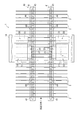
図1ないし図3において、部分加熱装置1は、所定の長さ寸法、断面寸法、強度の鋼棒からなる鉄筋材料2の一部を加熱することにより、一本の中で強度の異なる部分を有した鉄筋3を製造する装置である。具体的に、本実施形態での鉄筋3は、長手方向の中央側に高強度部分3Aを有し、両端側に普通強度部分3B,3Bを有している(図3参照)。
First Embodiment
[Overview of Partial Heating Device]
Hereinafter, a
In FIG. 1 to FIG. 3, the
図1、図2に示すように、部分加熱装置1は、鉄筋材料2の長手方向の一部である中央側を加熱部分として加熱する加熱手段10と、鉄筋材料2の加熱部分から外れた隣接部分への当該加熱部分からの熱伝導を制御する熱伝導制御手段20と、加熱手段10で加熱された加熱部分を冷却する冷却手段30と、各手段10,20,30を通過させるように複数の鉄筋材料2を連続的または間欠的に搬送する搬送手段40とを備え、各手段10,20,30,40をトンネル状のフレーム1Aで覆った構成である。
As shown in FIG. 1 and FIG. 2, the
[加熱手段の説明]
加熱手段10は、鉄筋材料2の長手方向の中央側に対応して設けられ、搬送手段40によって搬送される複数の鉄筋材料2の中央側の加熱部分を所定時間同時に加熱する構成である。このような加熱手段10としては、鉄筋材料2の上方および下方にそれぞれ配置された抵抗加熱炉、赤外線加熱炉や誘導加熱炉等の一対の加熱炉11を備えている。上方の加熱炉11がフレーム1Aの天井面に固定され、下方の加熱炉11が床面に設置されている。
[Description of heating means]
The heating means 10 is provided corresponding to the central side in the longitudinal direction of the reinforcing
加熱手段10による加熱部分の加熱温度は、加熱炉11の炉の温度として約1000℃であり、加熱される加熱部分の温度としては、700℃以上、望ましくは約900℃である。
The heating temperature of the heating portion by the heating means 10 is about 1000 ° C. as the temperature of the furnace of the
なお、加熱炉11として誘導加熱炉を採用する場合、鉄筋材料2の長手方向に対して当該鉄筋材料2の搬送方向(図1,図2での図中左から右へ向かう方向)が直交していることにより、搬送される鉄筋材料2を加熱コイル内に通すことが困難であることから、加熱コイルと鉄筋材料2とが上下に近接対向する構造の誘導加熱炉が用いられる。
When an induction heating furnace is employed as the
[熱伝導制御手段の説明]
熱伝導制御手段20は、加熱手段10における鉄筋材料2の長手方向に沿った両側に配置されており、冷却媒体を鉄筋材料2の加熱部分に隣接した隣接部分に直接あてて当該隣接部分を冷却し、加熱された加熱部分からの熱が隣接部分を含む鉄筋材料2の両側に伝導するのを抑制するように制御する。これらの熱伝導制御手段20としては、鉄筋材料2の上方に配置され、隣接部分に冷却媒体を供給する冷却媒体供給部21と、鉄筋材料2の下方に配置され、供給された冷却媒体を回収等する冷却媒体受け22とを備えている。冷却媒体供給部21がフレーム1Aの天井面に固定され、下方の冷却媒体受け22が床面に設置されている。
[Description of heat conduction control means]
The heat conduction control means 20 is disposed on both sides of the reinforcing
冷却媒体としては、水や油などの冷却液、空気や不活性ガスなどの冷却気体等である。熱伝導制御手段20には、それらの冷却媒体を温度調整しながら循環させる図示しない循環装置が接続されている。 The cooling medium is a cooling fluid such as water or oil, or a cooling gas such as air or an inert gas. The heat conduction control means 20 is connected to a circulation device (not shown) that circulates the cooling medium while adjusting its temperature.
熱伝導制御手段20による隣接部分の冷却温度は、隣接部分の温度として、鉄筋材料2の組成に変化が生じない温度、すなわち焼き入れされない温度であり、望ましくは500℃以下である。
The cooling temperature of the adjacent portion by the heat conduction control means 20 is a temperature at which no change occurs in the composition of the reinforcing
[冷却手段の説明]
冷却手段30は、加熱された加熱部分を冷却して焼き入れ等の熱処理を行う手段であり、高温となった加熱部分を冷却可能なように加熱手段10の下流側に近接して配置されている。このような冷却手段30も、熱伝導制御手段20と同様、鉄筋材料2の上方に配置され、冷却水等の冷却媒体を加熱部分に直接供給する冷却媒体供給部31と、下方に配置され、冷却媒体を回収等する冷却媒体受け32とを備えている。また同様に、冷却媒体供給部31がフレーム1Aの天井面に固定され、下方の冷却媒体受け32が床面に設置されている。
[Description of cooling means]
The
加熱部分が冷却手段30で冷却され、熱処理されることで得られる鉄筋3では、図3に示すように、加熱部分が高強度部分3Aとして形成され、加熱部分の両側の隣接部分を含む他の大部分が普通強度部分3Bとして形成され、高強度部分3Aと普通強度部分3Bとの間の僅かな領域が強度的な移行部分である強度移行部分3Cとして形成される。つまり、本実施形態の部分加熱装置1は、加熱手段10と冷却手段30とを備えることで、部分熱処理装置として機能する。
In the reinforcing
高強度部分3Aの強度は、685MPa以上である。普通強度部分3Bの強度は、鉄筋材料2が有している所定の強度で、490MPa以下である。そして、強度移行部分3Cは、490MPaから685MPaへ移行する強度勾配を有しており、その長さは鉄筋3の直径程度である。また、JIS規格によれば、普通強度部分3Bの降伏点または0.2%耐力は、JIS3112で規定されている通であり、高強度部分3Aの降伏点または0.2%耐力は、普通強度部分3Bのそれよりも大きい。
The strength of the
[搬送手段の説明]
搬送手段40は、鉄筋材料2の供給方向に沿って延設された2条のコンベア式の移送装置41,41を備えている。各移送装置41は、例えば、鉄筋材料2の両側に対応した位置に互いに離間し、かつ互いに平行に配置され、図示しない電動モータ等の駆動源により互いに同期して駆動される駆動側スプロケット42A、アイドラーとしての従動側スプロケット42B、各スプロケット42A,42Bに掛け回された無端状のコンベアチェーン43、コンベアチェーン43に取り付けられ、鉄筋材料2の端部を保持する複数の保持部44を有している。
[Description of transport means]
The transport means 40 includes two conveyor
また、搬送手段40において、一対の移送装置41の間には、これら移送装置41と平行な2条の支持レール45,45が設けられ、鉄筋材料2を支持レール45で下方から支持することにより、鉄筋材料2が撓むのを防止している。支持レール45は、各手段10,20,30とは平面視において重ならない位置に配置されている。
Further, in the transport means 40, two
[部分加熱装置の動作説明]
以上に説明した部分加熱装置1の動作について、以下に説明する。
先ず、部分加熱装置1の上流側(鉄筋材料2の供給方向の上流側)において、図示しない搬入装置により、鉄筋材料2を一旦停止状態にある搬送手段40の移送装置41上に搬入する。搬入が完了すると、移送装置41が所定時間作動し、搬入された鉄筋材料2を搬送方向へ搬送すると同時に、搬入装置による次の鉄筋材料2の搬入を可能にする。ただし、このような動作を所定時間毎に間欠的にではなく、連続的に行うようにしてもよい。
[Description of operation of partial heating device]
The operation of the
First, on the upstream side of the partial heating device 1 (upstream side in the supply direction of the reinforcing steel material 2), the reinforcing
以上の動作が繰り返されることで、複数の鉄筋材料2が加熱手段10および熱伝導制御手段20の通過位置に達すると、当該熱伝導制御手段20が隣接部分を冷却しながら、加熱手段10が鉄筋材料2の加熱部分を加熱する。加熱された鉄筋材料2が冷却手段30に達すると、冷却手段30が加熱部分を急冷し、焼き入れ等の熱処理を完了させる。これにより、高強度部分3Aおよび普通強度部分3Bを有した鉄筋3を得る。得られた鉄筋3は、搬送手段40の最下流まで十分に自然冷却されながら送られた後、ここから図示しない搬出装置にて所定位置に搬出される。
When the plurality of reinforcing
[第1実施形態の効果]
以上の本実施形態によれば、以下の効果がある。
(1)すなわち、部分加熱装置1では、加熱手段10での加熱を伴う熱処理により、加熱部分を高強度部分3Aとして形成され、隣接部分を含むその他の大部分を普通強度部分3Bとして形成されるため、熱処理時の熱影響を普通強度部分3Bまで及び難くでき、高強度部分3Aと普通強度部分3Bとの間に形成される強度移行部分3Cの長さを短くできる。また、このことにより、高強度部分3Aと普通強度部分3Bとの互いの境界を明確にでき、使い勝手が良好な鉄筋3を製造することができる。
[Effect of First Embodiment]
According to the above-described embodiment, the following effects can be obtained.
(1) That is, in the
(2)そして、加熱手段10で加熱された鉄筋材料2においては、加熱部分から隣接部分への熱伝導が熱伝導制御手段20によって制御されるから、高強度部分3Aと普通強度部分3Bとの互いの境界を一層明確にできる。
この際、熱伝導制御手段20は、隣接部分を冷却媒体で冷却するように構成されているので、隣接部分を低温に確実に冷却でき、加熱部分からの熱伝導を効果的に抑制するように制御できる。
(2) And, in the reinforcing
At this time, since the heat conduction control means 20 is configured to cool the adjacent part with the cooling medium, the adjacent part can be reliably cooled to a low temperature, so that the heat conduction from the heating part is effectively suppressed. It can control.
(3)搬送手段40によって複数の鉄筋材料2が連続的または間欠的に各手段10,20,30に搬送されるので、一本の中で強度の異なる高強度部分3Aと普通強度部分3Bとを有した鉄筋3を効率的に量産できる。さらに、搬送方向と鉄筋材料2の長手方向とが直交しているから、短い搬送距離を搬送する中で多くの鉄筋3を製造でき、装置1の小型化と鉄筋3の量産との両方を実現できる。
(3) Since the plurality of reinforcing
(4)加熱手段10が鉄筋材料2の長手方向の中央側に対応して設けられ、搬送手段40が鉄筋材料2の両端側を保持する保持部44を有しているため、長手方向の中央側に高強度部分3Aが形成され、両端側に普通強度部分3Bが形成された鉄筋3を製造できるとともに、両端側の保持部44は中央側の加熱手段10で加熱されることがなく、搬送手段40を良好な状態に維持でき、メンテナンス等に要する手間やコストを削減できる。
(4) Since the heating means 10 is provided corresponding to the center side in the longitudinal direction of the reinforcing
(5)加熱手段10で加熱された加熱部分を冷却する冷却手段30を備えているから、加熱部分を冷却手段30で冷却することで、加熱部分に焼き入れ等の熱処理を施すことができ、より高い強度の高強度部分を確実に形成できる。 (5) Since the cooling means 30 for cooling the heating part heated by the heating means 10 is provided, the heating part can be subjected to heat treatment such as quenching by cooling the heating part by the cooling means 30. It is possible to reliably form a high strength part of higher strength.
<第2実施形態>
図4には、本発明の第2実施形態に係る部分加熱装置1の平面図が示されている。図4では、前述した第1実施形態と同一の手段や装置等に関しては同一の符号を用いることとし、ここでのそれら同一の手段や装置等の説明を省略または簡略化する。
Second Embodiment
A plan view of a
図4において、本実施形態の部分加熱装置1では、加熱手段10および冷却手段30がそれぞれ、鉄筋材料2の両端側に対応して配置され、両端側の加熱部を加熱、冷却し、熱処理できるように構成されている。従って、熱伝導制御手段20は、両端側の加熱部分からの熱伝導を制御するために、一対の加熱手段10の間、すなわち鉄筋材料2の中央側に対応した位置で、当該加熱手段10に隣接して配置されている。これに対して、一対の移送装置41は、一対の加熱手段10の間に配置され、鉄筋材料2の中央側に対応した位置を保持する保持部44を有している。このことで移送装置41は、両端側の加熱手段10と平面視にて重ならない位置に配置されている。
In FIG. 4, in the
本実施形態によれば、第1実施形態とは構成が異なるが、第1実施形態の(1)ないし(3)、(5)と同様な効果を奏するうえ、(4)の効果に代えて、以下の(6)の効果がある。
(6)すなわち、加熱手段10が鉄筋材料2の長手方向の両端側に対応して設けられ、搬送手段40が鉄筋材料2の中央側を保持する保持部44を有しているため、長手方向の両端側に高強度部分が形成され、中央側に普通強度部分が形成された鉄筋3を製造できるとともに、中央側の保持部44は両端側の加熱手段10で加熱されることがなく、搬送手段40を良好な状態に維持でき、メンテナンス等に要する手間やコストを削減できる。
According to the present embodiment, although the configuration is different from that of the first embodiment, the same effects as (1) to (3) and (5) of the first embodiment can be obtained, and in place of the effect of (4) There are the following effects (6).
(6) That is, since the heating means 10 is provided corresponding to both end sides in the longitudinal direction of the reinforcing
なお、本発明は前述の各実施形態に限定されるものではなく、本発明の目的を達成できる範囲での変形、改良等は本発明に含まれるものである。 Note that the present invention is not limited to the above-described embodiments, and modifications, improvements, and the like in the range in which the object of the present invention can be achieved are included in the present invention.
前記実施形態では、熱伝導制御手段20が隣接部分に冷却媒体を直接供給する構成であったが、これに限定されず、例えば、鉄筋材料2よりも熱伝導性に優れた材料にて把持部材を構成し、当該鉄筋材料2の隣接部分を当該把持部材で把持することで、加熱部からの熱を把持部材を通して逃がし、隣接部分を含む他の部分に伝導するのを制御してもよい。
In the embodiment, the heat conduction control means 20 is configured to directly supply the cooling medium to the adjacent part, but the invention is not limited thereto. For example, the holding member is made of a material having a heat conductivity better than the reinforcing
前記実施形態の熱伝導制御手段20によれば、加熱手段10で加熱された加熱部分から隣接部分側への熱伝導や隣接部分側での放熱は免れず、加熱部分の温度も下がり易い状況にあるが、そのような熱伝導制御手段20に代えて、隣接部分を加熱部分よりも低い温度、具体的には焼き入れ温度よりも低い温度に加熱する加熱炉等で構成された熱伝導制御手段を用いてもよい。このような熱伝導制御手段によれば、隣接部分も所定温度に加熱されるので、加熱部分と隣接部分での温度勾配が小さくなり、加熱部分から隣接部分側への熱伝導を制御できて、高強度部分3Aと普通強度部分3Bとの互いの境界を明確にできるうえ、加熱部分の温度が下がり難くなり、加熱部分を迅速に加熱できる。
According to the heat conduction control means 20 of the embodiment, the heat conduction from the heating portion heated by the heating means 10 to the adjacent portion side and the heat radiation at the adjacent portion side can not be avoided, and the temperature of the heating portion tends to fall. However, instead of such heat conduction control means 20, a heat conduction control means comprising a heating furnace or the like for heating the adjacent part to a temperature lower than that of the heating part, specifically to a temperature lower than the quenching temperature. May be used. According to such a heat conduction control means, since the adjacent part is also heated to a predetermined temperature, the temperature gradient between the heating part and the adjacent part becomes small, and the heat conduction from the heating part to the adjacent part side can be controlled, The boundary between the
前記実施形態では、鉄筋材料2の長手方向と搬送方向とが直交していたが、互いに平行であってもよい。このような場合には、加熱コイル内を通過するように鉄筋材料を搬送でき、加熱手段として、誘導加熱炉を好適に用いることができる。また、このような場合でも、複数の誘導加熱炉を搬送方向と直交する方向に並設することで、複数の鉄筋材料を同時に搬送し、加熱できるようにすることが望ましく、こうすることで強度の異なる部分を有した鉄筋を効率的に量産することができる。
In the said embodiment, although the longitudinal direction of the reinforcing
前記実施形態では、鉄筋材料2として直線状のものを例示したが、高強度部分となる加熱部分に対応する位置で予め折り曲げられた鉄筋材料を用いてもよい。つまり、第1実施形態の場合では、長手方向の中央側で折り曲げられた鉄筋材料を用い、第2実施形態の場合では、長手方向の両端側で所定長さの余長を有した状態に折り曲げられた鉄筋材料を用いてもよい。この際、折曲角度としては、90°、135°、180°で、鉄筋材料の直径の数倍の曲げR(アール)を有することが一般的である。
In the said embodiment, although the linear thing was illustrated as the
その他、部分加熱装置の加熱手段や熱伝導制御手段等の具体的な構成や配置位置等は、前記実施異形態に限定されず、その実施にあたって任意に決められてよい。 In addition, the specific configuration, arrangement position, and the like of the heating means and heat conduction control means of the partial heating device are not limited to the above-described embodiment, but may be arbitrarily determined in implementation.
本発明は、鉄筋材料の一部を加熱したり、加熱、冷却することで熱処理を施したりする部分加熱装置に利用できる。 INDUSTRIAL APPLICABILITY The present invention can be used for a partial heating device that applies heat treatment by heating a part of reinforcing steel material, heating, and cooling.
1…部分加熱装置、2…鉄筋材料、3…鉄筋、3A…高強度部分、3B…普通強度部分、10…加熱手段、20…熱伝導制御手段、30…冷却手段、40…搬送手段、44…保持部。
DESCRIPTION OF
Claims (5)
前記搬送手段による搬送方向は、前記鉄筋材料の長手方向と直交する方向であり、
前記加熱手段は、前記鉄筋材料を挟んで配置される一対の加熱炉を有している
ことを特徴とする鉄筋材料の部分加熱装置。 A heating means for heating a part of the reinforcing material in the longitudinal direction as a heating portion, a conveying means for conveying a plurality of the reinforcing steel materials so as to pass the heating means, and a cooling of the heated part heated by the heating means Cooling means, and
The conveyance direction by the conveyance means is a direction orthogonal to the longitudinal direction of the reinforcing bar material,
The partial heating device for reinforcing steel material, the heating means includes a pair of heating furnaces disposed so as to sandwich the reinforcing steel material.
前記鉄筋材料の前記加熱部分から外れた隣接部分への当該加熱部分からの熱伝導を制御する熱伝導制御手段を備えていることを特徴とする鉄筋材料の部分加熱装置。 In the partial heating device for reinforcing material according to claim 1,
A partial heating device for reinforcing steel material, comprising heat conduction control means for controlling the heat conduction from the heating part to the adjacent part of the reinforcing steel material which has deviated from the heating part.
前記熱伝導制御手段は、前記隣接部分を冷却媒体で冷却するように構成されているか、または前記加熱部分よりも低い温度に前記隣接部分を加熱するように構成されている
ことを特徴とする鉄筋材料の部分加熱装置。 In the partial heating device for reinforcing material according to claim 2,
The heat conduction control means is configured to cool the adjacent portion with a cooling medium, or is configured to heat the adjacent portion to a temperature lower than the heating portion. Partial heating device for materials.
前記加熱手段は、前記鉄筋材料の長手方向の中央側に対応して設けられ、前記搬送手段は、前記鉄筋材料の長手方向の両端側を保持する保持部を有している
ことを特徴とする鉄筋材料の部分加熱装置。 In the partial heating device of the reinforcing material according to any one of claims 1 to 3 ,
The heating means is provided corresponding to the central side in the longitudinal direction of the reinforcing bar material, and the conveying means has holding portions for holding the both end sides in the longitudinal direction of the reinforcing bar material. Partial heating device for rebar material.
前記加熱手段は、前記鉄筋材料の長手方向の両端側に対応して設けられ、前記搬送手段は、前記鉄筋材料の長手方向の中央側を保持する保持部を有している
ことを特徴とする鉄筋材料の部分加熱装置。 In the partial heating device of the reinforcing material according to any one of claims 1 to 3 ,
The heating means is provided corresponding to both end sides in the longitudinal direction of the reinforcing bar material, and the conveying means has a holding portion for holding the central side in the longitudinal direction of the reinforcing bar material. Partial heating device for rebar material.
Priority Applications (1)
| Application Number | Priority Date | Filing Date | Title |
|---|---|---|---|
| JP2014200509A JP6510207B2 (en) | 2014-09-30 | 2014-09-30 | Partial heating device for reinforcing material |
Applications Claiming Priority (1)
| Application Number | Priority Date | Filing Date | Title |
|---|---|---|---|
| JP2014200509A JP6510207B2 (en) | 2014-09-30 | 2014-09-30 | Partial heating device for reinforcing material |
Publications (2)
| Publication Number | Publication Date |
|---|---|
| JP2016072094A JP2016072094A (en) | 2016-05-09 |
| JP6510207B2 true JP6510207B2 (en) | 2019-05-08 |
Family
ID=55864890
Family Applications (1)
| Application Number | Title | Priority Date | Filing Date |
|---|---|---|---|
| JP2014200509A Active JP6510207B2 (en) | 2014-09-30 | 2014-09-30 | Partial heating device for reinforcing material |
Country Status (1)
| Country | Link |
|---|---|
| JP (1) | JP6510207B2 (en) |
Families Citing this family (2)
| Publication number | Priority date | Publication date | Assignee | Title |
|---|---|---|---|---|
| JP6728001B2 (en) * | 2016-09-14 | 2020-07-22 | 高周波熱錬株式会社 | Rebar marking device |
| JP7029985B2 (en) * | 2018-03-12 | 2022-03-04 | 高周波熱錬株式会社 | Reinforcing bar marking device and reinforcing bar |
Family Cites Families (4)
| Publication number | Priority date | Publication date | Assignee | Title |
|---|---|---|---|---|
| JPS5333947U (en) * | 1976-08-30 | 1978-03-24 | ||
| JPS60156691U (en) * | 1984-03-29 | 1985-10-18 | 株式会社東芝 | induction heating device |
| JP2002371317A (en) * | 2001-06-19 | 2002-12-26 | Fuji Electronics Industry Co Ltd | Device and method for induction hardening of axial workpiece |
| JP6023476B2 (en) * | 2012-06-08 | 2016-11-09 | 高周波熱錬株式会社 | Rebar structure |
-
2014
- 2014-09-30 JP JP2014200509A patent/JP6510207B2/en active Active
Also Published As
| Publication number | Publication date |
|---|---|
| JP2016072094A (en) | 2016-05-09 |
Similar Documents
| Publication | Publication Date | Title |
|---|---|---|
| RU2014103103A (en) | METHOD FOR HEATING THE FITTING ITEM FOR THE NEXT HAZARDING UNDER THE PRESS, AND ALSO THE THREAD FURNACE FOR THE HEATING OF THE ZONE HEATED UP TO THE TEMPERATURE OF THE FITTING ITEM UP TO A HIGH TEMPERATURE | |
| JP6211364B2 (en) | Heat treatment method for ring member and heat treatment equipment for ring member | |
| JP6510207B2 (en) | Partial heating device for reinforcing material | |
| TW201433640A (en) | Handling device | |
| JP2009538263A5 (en) | ||
| RU2020113320A (en) | METHOD FOR CONNECTING STEEL RAILS WITH ADJUSTABLE WELDING HEAT SUPPLY | |
| TWI574833B (en) | Steel plate heating method and steel plate heating device | |
| ES2861445T3 (en) | Hot press device | |
| JP4373883B2 (en) | Induction heat treatment method and induction heat treatment apparatus | |
| TWI568690B (en) | And a glass-molded body | |
| JP2018532882A (en) | Method for producing starting materials for producing metal parts having regions of different strength | |
| JP2008024966A (en) | Method for controlling furnace temperature in continuous type heating furnace, and method for producing steel material | |
| WO2007088439A3 (en) | Gas-fired furnace for continuous heating of metal bars | |
| JP2005330504A (en) | Partial heat treatment method for member to be heat-treated and device therefor | |
| WO2018061325A1 (en) | Chain type transport device | |
| JP7118637B2 (en) | High frequency induction heating device | |
| US1795819A (en) | Heat-treating furnace | |
| US20160353527A1 (en) | Customized Retainer for Induction Heating Coil | |
| EP1718118A4 (en) | Method and device for induction heating and hardening apparatus | |
| KR101917441B1 (en) | Rolling device | |
| JP2005325422A (en) | Method for partially heat-treating member to be heat-treated, and apparatus therefor | |
| JP2016176627A (en) | Heating device | |
| JP2009174037A (en) | High-frequency heating coil of induction heater | |
| JP2005126746A (en) | Device for heating small-diameter metal bar material, heating and cooling apparatus and heat treatment method | |
| RU2007104311A (en) | METHOD FOR THERMAL TREATMENT OF PRODUCTS FROM HIGH-STRENGTH MARTENSITY-AGING STEELS |
Legal Events
| Date | Code | Title | Description |
|---|---|---|---|
| A621 | Written request for application examination |
Free format text: JAPANESE INTERMEDIATE CODE: A621 Effective date: 20170705 |
|
| A977 | Report on retrieval |
Free format text: JAPANESE INTERMEDIATE CODE: A971007 Effective date: 20180720 |
|
| A131 | Notification of reasons for refusal |
Free format text: JAPANESE INTERMEDIATE CODE: A131 Effective date: 20180731 |
|
| A521 | Request for written amendment filed |
Free format text: JAPANESE INTERMEDIATE CODE: A523 Effective date: 20180925 |
|
| TRDD | Decision of grant or rejection written | ||
| A01 | Written decision to grant a patent or to grant a registration (utility model) |
Free format text: JAPANESE INTERMEDIATE CODE: A01 Effective date: 20190312 |
|
| A61 | First payment of annual fees (during grant procedure) |
Free format text: JAPANESE INTERMEDIATE CODE: A61 Effective date: 20190404 |
|
| R150 | Certificate of patent or registration of utility model |
Ref document number: 6510207 Country of ref document: JP Free format text: JAPANESE INTERMEDIATE CODE: R150 |
|
| R250 | Receipt of annual fees |
Free format text: JAPANESE INTERMEDIATE CODE: R250 |
|
| R250 | Receipt of annual fees |
Free format text: JAPANESE INTERMEDIATE CODE: R250 |
|
| R250 | Receipt of annual fees |
Free format text: JAPANESE INTERMEDIATE CODE: R250 |