WO2018061325A1 - Chain type transport device - Google Patents
Chain type transport device Download PDFInfo
- Publication number
- WO2018061325A1 WO2018061325A1 PCT/JP2017/021092 JP2017021092W WO2018061325A1 WO 2018061325 A1 WO2018061325 A1 WO 2018061325A1 JP 2017021092 W JP2017021092 W JP 2017021092W WO 2018061325 A1 WO2018061325 A1 WO 2018061325A1
- Authority
- WO
- WIPO (PCT)
- Prior art keywords
- arm
- rod
- chain type
- pair
- type conveying
- Prior art date
Links
Images


Classifications
-
- B—PERFORMING OPERATIONS; TRANSPORTING
- B65—CONVEYING; PACKING; STORING; HANDLING THIN OR FILAMENTARY MATERIAL
- B65G—TRANSPORT OR STORAGE DEVICES, e.g. CONVEYORS FOR LOADING OR TIPPING, SHOP CONVEYOR SYSTEMS OR PNEUMATIC TUBE CONVEYORS
- B65G17/00—Conveyors having an endless traction element, e.g. a chain, transmitting movement to a continuous or substantially-continuous load-carrying surface or to a series of individual load-carriers; Endless-chain conveyors in which the chains form the load-carrying surface
- B65G17/06—Conveyors having an endless traction element, e.g. a chain, transmitting movement to a continuous or substantially-continuous load-carrying surface or to a series of individual load-carriers; Endless-chain conveyors in which the chains form the load-carrying surface having a load-carrying surface formed by a series of interconnected, e.g. longitudinal, links, plates, or platforms
-
- B—PERFORMING OPERATIONS; TRANSPORTING
- B65—CONVEYING; PACKING; STORING; HANDLING THIN OR FILAMENTARY MATERIAL
- B65G—TRANSPORT OR STORAGE DEVICES, e.g. CONVEYORS FOR LOADING OR TIPPING, SHOP CONVEYOR SYSTEMS OR PNEUMATIC TUBE CONVEYORS
- B65G17/00—Conveyors having an endless traction element, e.g. a chain, transmitting movement to a continuous or substantially-continuous load-carrying surface or to a series of individual load-carriers; Endless-chain conveyors in which the chains form the load-carrying surface
- B65G17/30—Details; Auxiliary devices
- B65G17/32—Individual load-carriers
-
- C—CHEMISTRY; METALLURGY
- C21—METALLURGY OF IRON
- C21D—MODIFYING THE PHYSICAL STRUCTURE OF FERROUS METALS; GENERAL DEVICES FOR HEAT TREATMENT OF FERROUS OR NON-FERROUS METALS OR ALLOYS; MAKING METAL MALLEABLE, e.g. BY DECARBURISATION OR TEMPERING
- C21D1/00—General methods or devices for heat treatment, e.g. annealing, hardening, quenching or tempering
-
- F—MECHANICAL ENGINEERING; LIGHTING; HEATING; WEAPONS; BLASTING
- F27—FURNACES; KILNS; OVENS; RETORTS
- F27B—FURNACES, KILNS, OVENS, OR RETORTS IN GENERAL; OPEN SINTERING OR LIKE APPARATUS
- F27B9/00—Furnaces through which the charge is moved mechanically, e.g. of tunnel type; Similar furnaces in which the charge moves by gravity
- F27B9/14—Furnaces through which the charge is moved mechanically, e.g. of tunnel type; Similar furnaces in which the charge moves by gravity characterised by the path of the charge during treatment; characterised by the means by which the charge is moved during treatment
- F27B9/20—Furnaces through which the charge is moved mechanically, e.g. of tunnel type; Similar furnaces in which the charge moves by gravity characterised by the path of the charge during treatment; characterised by the means by which the charge is moved during treatment the charge moving in a substantially straight path tunnel furnace
- F27B9/24—Furnaces through which the charge is moved mechanically, e.g. of tunnel type; Similar furnaces in which the charge moves by gravity characterised by the path of the charge during treatment; characterised by the means by which the charge is moved during treatment the charge moving in a substantially straight path tunnel furnace being carried by a conveyor
-
- C—CHEMISTRY; METALLURGY
- C21—METALLURGY OF IRON
- C21D—MODIFYING THE PHYSICAL STRUCTURE OF FERROUS METALS; GENERAL DEVICES FOR HEAT TREATMENT OF FERROUS OR NON-FERROUS METALS OR ALLOYS; MAKING METAL MALLEABLE, e.g. BY DECARBURISATION OR TEMPERING
- C21D9/00—Heat treatment, e.g. annealing, hardening, quenching or tempering, adapted for particular articles; Furnaces therefor
- C21D9/32—Heat treatment, e.g. annealing, hardening, quenching or tempering, adapted for particular articles; Furnaces therefor for gear wheels, worm wheels, or the like
Definitions
- the present invention relates to a chain type conveying apparatus for conveying a workpiece to be heat-treated in a heat treatment furnace.
- a transport device that transports a workpiece to be heat-treated in a heat treatment furnace for example, a transport device that transports the work on a mesh belt and transports the inside of the heat treatment furnace is known (see, for example, Patent Document 1). It is known to be formed by a plurality of generally flat metal wire spirals having an upper transport surface, a lower surface and side edges, each extending across the belt (e.g. 2).
- a transport device that transports a slat plate with rollers attached to both ends by roller guides provided at both ends in the width direction, and transports the workpieces side by side on the slat plate (see, for example, Patent Document 3).
- support rods that extend the rotation shafts of the endless chain pieces installed at both ends of the cradle for receiving goods are fitted to both ends of the pipe-shaped conveyance rod, and the endless chain is driven to drive the endless chain.
- a conveying device that pushes and conveys a cradle is known (see Patent Document 4).
- the mesh belt is made of a metal wire, heat resistance is ensured, but a large amount of wire is required to obtain sufficient strength. Since the mesh belt is made finer, the front and back air permeability cannot be sufficiently obtained, and in the case of a transfer device using a slat plate, no air permeability from the lower side of the work is obtained. . For this reason, in any case, it is difficult to heat-treat the workpiece uniformly. In addition, for example, when transporting a workpiece having a protruding portion such as a gear with a shaft, it is difficult to transport the workpiece while maintaining the same posture on a plane such as a mesh belt or a slat plate. There is.
- the present invention was devised in view of the above-described conventional problems, and an object thereof is to provide a chain type conveying apparatus capable of more uniform heat treatment of a workpiece.
- a chain type conveying apparatus is a chain type conveying apparatus that conveys a workpiece to be heat-treated, and a pair of chains that are arranged along the conveying direction and spaced apart from each other, and spans between the pair of chains. And a plurality of spanning rods that circulate together with the pair of chains, and a plurality of arms that are provided on the spanning rod along the transport direction and on which the workpiece is placed. To do.
- the pair of chains each have a protruding rod protruding in a direction facing each other
- the bridge rod has an insertion portion into which the protruding rod is inserted at both ends, and one end is It is fixed to the projecting rod, and the other end is inserted so as to be relatively movable in the longitudinal direction of the spanning rod.
- the arm is provided across two different connecting rods, attached to one of the connecting rods, and placed on the other connecting rod.
- the arm has a rotation support end, and the rotation support end is rotatably attached to the bridge rod.
- the arm is mounted on the other bridge rod so as to be relatively movable in the transport direction.
- a plurality of arm pairs each including two arms on which a single workpiece is placed and spaced apart in the longitudinal direction of the spanning rod are provided in the transport direction.
- the two matching arm pairs are characterized in that two arms forming the other arm pair are arranged between the two arms forming one arm pair.
- the workpiece can be heated from the entire circumference, the workpiece can be uniformly heat-treated, and the measures against the hot elongation of the mechanism can be improved.
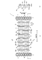
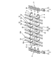
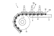
- FIG. 1 is an explanatory diagram for explaining a chain-type transport device according to the present embodiment, where (a) is a plan view showing a part of the chain-type transport device in the transport direction, and (b) is a view taken along line BB in FIG. FIG. It is a partially exploded perspective view which shows the structure of the chain type conveying apparatus which concerns on this embodiment.
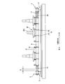
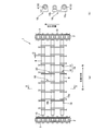
- FIG. 2 is a partial cross-sectional view taken along line AA in FIG. It is a perspective view which shows the structure of the roller chain of the chain type conveying apparatus shown in FIG. It is a figure which shows the sprocket periphery of the drive side of the chain type conveying apparatus which concerns on this embodiment.
- a chain type conveying device for conveying the inside of a heat treatment furnace to heat-treat a gear with a shaft as a workpiece
- the interior of the heat treatment furnace is made an atmosphere of uniform temperature by a heater and a circulation fan (both not shown) installed therein.
- the chain type conveying apparatus 1 As shown in FIG. 1 to FIG. 3, the chain type conveying apparatus 1 according to the present embodiment is arranged at intervals in a direction intersecting with the conveying direction (hereinafter referred to as the intersecting direction) and extends along the conveying direction.
- Two rails 2 a pair of endless roller chains 3 that are guided by each rail 2 and move on each rail 2, a plurality of spanning rods 4 spanned between the pair of endless roller chains 3, and auxiliary And a pipe 23.
- the roller chain 3 is separated from each other between two opposed inner plates 5 by two cylindrical bushes 7 into which two rollers 6 are inserted.
- the two inner plates 5 are connected to the bush 7 and are provided with through-holes 8 therethrough, and two adjacent inner links.
- 9 has two shaft portions 10 inserted into one of the bushes 7, and a plurality of outer links 12 each connecting the two shaft portions 10 with an outer plate 11 are connected to each other to be endless. ing.
- the two shaft portions 10 are each extended in a direction in which the two roller chains 3 face each other, and the two shaft portions 10 included in the outer link 12 correspond to protruding rods.
- the shaft portion 10 is a stepped pin that is inserted from one side of the roller chain 3 and protrudes to the opposite side (indicated by ⁇ in the figure), and then crimped (indicated by ⁇ in the figure).
- the shaft portion 10 itself can also be rotated so that the inner plate 5 and the outer plate 11 can be bent while sandwiching the entire inner link 9 and outer link 12 (indicated by ⁇ in the figure).
- the two rails 2 are configured such that a plate-like rail body 14 is provided on a pedestal 13 so as to stand vertically along the transport direction.
- the thickness of the plate-like rail body 14 is narrower than the distance between the inner plates 5 of the inner links 9 constituting the roller chain 3.
- the two roller chains 3 are wound around a sprocket 15 provided on the end side of each rail 2 and driven by a driving device (not shown) provided with the sprocket 15.
- the roller 6 rolls on the rail 2 while being guided by the opposed inner plate 5 and outer plate 11 while the roller 6 rolls.
- a guide 22 is provided on the outer peripheral side of the sprocket 15 at the end of the chain type conveying device 1.
- a spanning rod 4 is spanned on each of the shaft portions 10 provided on the two roller chains 3 and extending opposite to each other, and the span is spanned between the two roller chains 3.
- the transfer rods 4 are arranged at equal intervals in the transport direction. Further, an auxiliary pipe 23 for temperature adjustment is disposed between the spanning rods 4.
- Each bridging rod 4 has a cylindrical shape penetrating in the longitudinal direction, and two shaft portions 10 facing each other are inserted from both ends.
- One of the two shaft portions 10 inserted in the spanning rod 4 is connected together with the spanning rod 4 by a split pin 17 penetrating in the diameter direction of the spanning rod 4, and the other is a rail.
- the shaft portion 10 is engaged so as to be movable in the insertion / removal direction in a state where it is not restricted by 2 or the like, that is, in a state having a gap S as shown in FIG.
- forms the cylinder shape is equivalent to an insertion part.
- the auxiliary pipe 23 also has the same mounting structure as the spanning rod 4.
- the plurality of connecting rods 4 and the auxiliary pipes 23 provided between the two roller chains 3 are different in the side where the ends connected by the split pins 17 between the adjacent connecting rods 4 and the auxiliary pipes 23 are located. To do. That is, the plurality of spanning rods 4 and the auxiliary pipes 23 arranged in the transport direction are alternately arranged with the bridging rods 4 and the auxiliary pipes 23 connected by the split pins 17 on one end side. ing.
- the bridge rod 4 and the auxiliary pipe 23 are movable on one side in the insertion / removal direction, even if the bridge rod 4 and the auxiliary pipe 23 are heated and extended due to heating in the heat treatment furnace, they Since it can be absorbed by the movement, the hot elongation does not affect the driving of the roller chain 3.
- Each bridging rod 4 has a workpiece (an exemplary gear) W that is transported in a unified manner on either the front side or the rear side of the two shaft portions 10 of the outer link 12 in the transport direction.
- a plurality of arms 18 on which are mounted is rotatably provided.
- the arm 18 is a plate-like member in which one end portion in the longitudinal direction is rotatably provided on the bridge rod 4.
- the arm 18 is welded to the bridge rod 4 (indicated by D in the figure), so that all the arms 18 can be simultaneously rolled.
- the arm 18 (18c, 18d) which is rotated with the shaft portion 10 of the chain 3 or halved by processing the groove 16 in the bridge rod 4 as shown in FIGS. 8 (b) and 8 (c).
- the arm 18 can be individually rotated by being sandwiched between the two and welded with the both inserted into the groove 16 (indicated by F in the figure).
- the position in the crossing direction can also be fixed.
- the arm 18 When the roller rod 3 is driven to move the transfer rod 4, the arm 18 is arranged in the longitudinal direction along the transfer direction, and the transfer rod 4 provided with the arm 18 is rearward in the transfer direction.
- the other end side in the longitudinal direction is placed on another bridging rod 4 provided with the arm 18 located on the side.
- the upper edge of the arm 18 is substantially horizontal.
- the bridging rod 4 is bridged between all the opposed shaft portions 10, but there may be a bridging rod 4 in which the arm 18 is not provided. Since the arm 18 is merely mounted on the other end side in the transport direction not attached to the shaft portion 10 without being fixed to the bridge rod 4, the arm 18 is heated in the longitudinal direction by heating in the heat treatment furnace. However, the driving of the roller chain 3 is not affected.
- each of the arms 18 provided in each bridging rod 4 are arranged at appropriate intervals in the longitudinal direction of the bridging rod 4, that is, in the crossing direction substantially perpendicular to the transport direction. More specifically, each of the arms 18 provided on two adjacent connecting rods 4 of the connecting rods 4 provided with the arms 18 is provided on one connecting rod 4. A proximity portion 20 is arranged such that the rotation support end 18a side of the arm 18 and the placement support end 18b side of the arm 18 provided on the other spanning rod 4 are close to each other in the crossing direction. It is provided at intervals in the crossing direction.
- each bridging rod 4 the rotation support end 18 a of one arm 18 and the mounting support end 18 b of the other arm 18 are not in contact with each other even if the bridging rod 4 extends in the crossing direction.
- G (see FIG. 1) is provided, and the proximity portions 20 are provided at a plurality of positions at intervals in the crossing direction.
- the adjacent part 20 in the adjacent part 20 mutually adjacent
- the proximity portion 20a located on the most end side (for example, the left side in FIG. 1) of a certain spanning rod 4 it is on the left side of the rotation support end 18a of the arm 18 provided on the spanning rod 4.
- the mounting support end 18b of the adjacent spanning rod 4 is located.
- the placement support end 18b of the adjacent spanning rod 4 is positioned on the right side of the rotation support end 18a of the arm 18 provided on the spanning rod 4. Yes.
- the placement support end 18b of the adjacent spanning rod 4 is located on the left side of the rotation support end 18a of the arm 18 provided on the spanning rod 4. Yes.
- the plurality of adjacent portions 20 provided in the intersecting direction are provided with the rotation support end 18a of the arm 18 included in the bridge rod 4 and the placement support end 18b of the arm 18 included in the adjacent bridge rod 4. The positions are alternately interchanged.
- the gear W is placed and conveyed on an arm pair 19 composed of two arms 18 arranged at intervals in the longitudinal direction of the bridge rod 4.
- a plurality of arm pairs 19 are provided in the transport direction, and two arm pairs 19 adjacent in the transport direction are two arms 18 forming the other arm pair 19 between two arms 18 forming one arm pair 19. 18 is arranged.
- the chain-type transport device 1 transports the shaft-equipped gear W for heat treatment, as shown in FIG.
- a gear W crosses over the arm 18 and the shaft Wa can be inserted between the bridging rods 4 adjacent to each other in the conveying direction so as to be placed along the vertical direction.
- the problem can be solved and maintained in the same posture on the plane.
- the two arms 18 arranged across the gear W correspond to the arm pair 19, and the space H between the arm pair 19 is a guideline for placing the gear W, which is a workpiece, on the chain type conveyance device 1. It can be placed by hand or robot.
- any gear W can be made to have uniform processing conditions.
- the gears W on the arms 18 provided on the plurality of spanning rods 4 that move together with the roller chain 3 that is driven and circulated by the driving device are heated while being transported, and are moved to the transport device or the like in the next process. .
- the plurality of transfer rods 4 that are bridged between a pair of roller chains 3 that are spaced apart from each other and circulate together with the pair of roller chains 3 are heat-treated. Since the arm 18 on which the gear W is mounted is provided, the portion on which the gear W is mounted is opened in the vertical direction. Since the gear W is transported on the heater 16 by the chain transport device 1, heat treatment can be performed efficiently. Further, since the portion where the gear W is placed is opened in the vertical direction, even if the gear W is provided with the axis Wa, the gear W is substantially arranged by arranging the axis Wa in the vertical direction. It is possible to arrange with the same posture. For this reason, it is possible to heat-process the some gear W mounted on the chain type conveying apparatus 1 more uniformly.
- roller chains 3 two shaft portions 10 projecting in opposite directions are inserted into both end portions of the bridging rod 4, one end portion is fixed by the split pin 17, and the other Since the end portion is inserted so as to be relatively movable in the longitudinal direction of the bridging rod 4, even if the bridging rod 4 expands due to heat of heat treatment or contracts again after the expansion, the roller chain 3 is sprocketed. 15 or it is possible to prevent an excessive load from acting on the rail 2 or the like.
- the transfer rod 4 can be removed simply by removing the split pin 17, so that the transfer is performed by changing the shape of the arm 18 depending on the shape of the gear (workpiece) W.
- the rod 4 can be easily replaced.
- the gear W can be disposed in a stable state. At this time, the arm 18 is attached to one of the two spanning rods 4 and freely rotates, so that the circulating roller chain 3 can be smoothly wound around the sprocket 15.
- the arm 18 Since the arm 18 is pivotally attached to the bridge rod 4 at the leading end in the conveying direction, the arm 18 is suspended from the bridge rod 4 below the rail 2 by the sprocket 15. It is possible to dispose the mounting support end 18b of the arm 18 on the bridge rod 4 located on the rear side in the transport direction simply by pulling up to the upper side of the rail 2.
- the auxiliary pipe 23 is heated and stored in a heat treatment furnace, and has an effect that the gear W can be heated uniformly by applying radiant heat to the gear (work) W from below. Depending on the distribution, it may be replaced with a different thickness.
- the auxiliary pipe 23 does not need to be installed, and in this way, the area of the space H can be widened, and the projecting portion Wa has a large area and a long work W. Even if it exists, it can arrange
- the pair of arms 18 on which the gear W is placed has been described.
- the pair of arms has a rotation support end and a placement support. You may connect with the connection material 24 by the edge. In this case, it is possible to further stabilize the placement of the gear W.
- the position where the gear W is placed is recognized as a rectangular portion formed by the pair of arms, the connecting portion, and the bridge rod. This makes it easy to automate the process of placing a workpiece such as a gear.
Abstract
[Problem] To provide a chain type transport device which enables a workpiece to be heated all around, the workpiece to be uniformly heat-treated, and a countermeasure against the thermal elongation of the mechanism to be improved. [Solution] Provided is a chain type transport device 1 for transporting a workpiece (gear) to be heat treated, wherein the chain type transport device 1 has a pair of chains 3, 3 extending in the transport direction and arranged at a distance from each other; a plurality of bridging rods 4 mounted across the pair of chains and circulating with the pair of chains; and a plurality of arms 18 which are mounted to the bridging rods so as to extend in the transport direction and on which the workpiece is placed.
Description
本発明は、熱処理するワークを熱処理炉内で搬送するチェーン式搬送装置に関する。
The present invention relates to a chain type conveying apparatus for conveying a workpiece to be heat-treated in a heat treatment furnace.
熱処理するワークを熱処理炉内で搬送する搬送装置としては、例えば、ワークをメッシュベルトに乗せて熱処理炉内を搬送する搬送装置が知られており(例えば、特許文献1参照)、そのメッシュベルトとして、上部搬送面、下部面及び側縁を有し、各々がベルトを横断して伸長する概ね平らな金属製の複数のワイヤー渦巻線により形成されていることが知られている(例えば、特許文献2参照)。
As a transport device that transports a workpiece to be heat-treated in a heat treatment furnace, for example, a transport device that transports the work on a mesh belt and transports the inside of the heat treatment furnace is known (see, for example, Patent Document 1). It is known to be formed by a plurality of generally flat metal wire spirals having an upper transport surface, a lower surface and side edges, each extending across the belt (e.g. 2).
また、幅方向の両端に設けられたローラーガイドにより、両端にローラーを付けたスラット板を搬送し、スラット板上にワークを並べて搬送する搬送装置が知られている(例えば、特許文献3参照)。また、商品を受容する受台の両端に配備されたエンドレスチェーンのコマの回転軸を延長した支持棒を、パイプ状の搬送棒の両端に嵌合し、エンドレスチェーンを駆動することにより搬送棒で受台を押して搬送させる搬送装置が知られている(特許文献4参照)。
In addition, a transport device is known that transports a slat plate with rollers attached to both ends by roller guides provided at both ends in the width direction, and transports the workpieces side by side on the slat plate (see, for example, Patent Document 3). . In addition, support rods that extend the rotation shafts of the endless chain pieces installed at both ends of the cradle for receiving goods are fitted to both ends of the pipe-shaped conveyance rod, and the endless chain is driven to drive the endless chain. A conveying device that pushes and conveys a cradle is known (see Patent Document 4).
上記のようにメッシュベルトを用いた搬送装置の場合には、メッシュベルトが金属製のワイヤーにより構成されているので、耐熱性は確保されているが、十分な強度を得るために大量のワイヤーが用いられるためメッシュベルトの目が細かくなることにより、表裏方向の通気性が十分に得られず、スラット板を用いた搬送装置の場合には、ワークの下側からの通気性が全く得られない。このため、いずれの場合であっても、ワークを均一に熱処理することが難しい。また、例えば、軸付きの歯車のように突出部を有するワークを搬送する場合には、メッシュベルトやスラット板のような平面上にワークを同一の姿勢を維持させて搬送することが難しいという課題がある。
In the case of the transport device using the mesh belt as described above, since the mesh belt is made of a metal wire, heat resistance is ensured, but a large amount of wire is required to obtain sufficient strength. Since the mesh belt is made finer, the front and back air permeability cannot be sufficiently obtained, and in the case of a transfer device using a slat plate, no air permeability from the lower side of the work is obtained. . For this reason, in any case, it is difficult to heat-treat the workpiece uniformly. In addition, for example, when transporting a workpiece having a protruding portion such as a gear with a shaft, it is difficult to transport the workpiece while maintaining the same posture on a plane such as a mesh belt or a slat plate. There is.
本発明は上記従来の課題に鑑みて創案されたものであって、ワークのより均一な熱処理が可能なチェーン式搬送装置を提供することを目的とする。
The present invention was devised in view of the above-described conventional problems, and an object thereof is to provide a chain type conveying apparatus capable of more uniform heat treatment of a workpiece.
本発明にかかるチェーン式搬送装置は、熱処理するワークを搬送するチェーン式搬送装置であって、搬送方向に沿うとともに互いに間隔を隔てて配置された一対のチェーンと、前記一対のチェーン間に架け渡されて前記一対のチェーンとともに循環する複数の架け渡しロッドと、前記架け渡しロッドに前記搬送方向に沿って設けられ前記ワークが載置される複数のアームと、を有していることを特徴とする。
A chain type conveying apparatus according to the present invention is a chain type conveying apparatus that conveys a workpiece to be heat-treated, and a pair of chains that are arranged along the conveying direction and spaced apart from each other, and spans between the pair of chains. And a plurality of spanning rods that circulate together with the pair of chains, and a plurality of arms that are provided on the spanning rod along the transport direction and on which the workpiece is placed. To do.
また、前記一対のチェーンは、互いに対向する方向に突出された突出ロッドを各々有し、前記架け渡しロッドは、両端部に前記突出ロッドが挿入される挿入部を有し、一方の端部が前記突出ロッドに固定され、他方の端部は前記架け渡しロッドの長手方向に相対移動可能に挿入されていることを特徴とする。
Further, the pair of chains each have a protruding rod protruding in a direction facing each other, the bridge rod has an insertion portion into which the protruding rod is inserted at both ends, and one end is It is fixed to the projecting rod, and the other end is inserted so as to be relatively movable in the longitudinal direction of the spanning rod.
また、前記アームは、互いに異なる2本の前記架け渡しロッドに渡って設けられ、一方の前記架け渡しロッドに取り付けられ、他方の前記架け渡しロッド上に載置されることを特徴とする。
Further, the arm is provided across two different connecting rods, attached to one of the connecting rods, and placed on the other connecting rod.
また、前記アームは、回動支持端を有し、当該回動支持端が前記架け渡しロッドに回動自在に取り付けられていることを特徴とする。
The arm has a rotation support end, and the rotation support end is rotatably attached to the bridge rod.
また、前記アームは、前記他方の架け渡しロッドと、搬送方向において相対移動可能に載せられていることを特徴とする。
Further, the arm is mounted on the other bridge rod so as to be relatively movable in the transport direction.
また、前記架け渡しロッドの長手方向に間隔を隔てて配置され単一の前記ワークが載置される2つの前記アームからなるアーム対が、前記搬送方向に複数設けられており、搬送方向において隣り合う2つの前記アーム対は、一方の前記アーム対をなす2つの前記アーム間に、他方の前記アーム対をなす2つのアームが配置されることを特徴とする。
In addition, a plurality of arm pairs each including two arms on which a single workpiece is placed and spaced apart in the longitudinal direction of the spanning rod are provided in the transport direction. The two matching arm pairs are characterized in that two arms forming the other arm pair are arranged between the two arms forming one arm pair.
本発明によれば、ワークを全周から加熱できて、ワークの均一な熱処理が可能であって、機構の熱延び対策も改善することができる。
According to the present invention, the workpiece can be heated from the entire circumference, the workpiece can be uniformly heat-treated, and the measures against the hot elongation of the mechanism can be improved.
以下に、本発明にかかるチェーン式搬送装置の好適な一実施形態を、添付図面を参照して詳細に説明する。
Hereinafter, a preferred embodiment of a chain type conveying apparatus according to the present invention will be described in detail with reference to the accompanying drawings.
本実施形態では、例えば、ワークとしての軸付の歯車を熱処理すべく熱処理炉内を搬送するためのチェーン式搬送装置を例に挙げて説明する。熱処理炉内は、その内部に設置したヒーターと循環ファン(共に図示せず)によって、均一な温度の雰囲気とされている。図1~図3に示すように、本実施形態に係るチェーン式搬送装置1は、搬送方向と交差する方向(以下、交差方向という)に互いに間隔を隔てて配置され、搬送方向に沿って延びる2本のレール2と、各々のレール2に案内されて各レール2上を移動する一対の無端ローラーチェーン3と、一対の無端ローラーチェーン3間に掛け渡される複数の架け渡しロッド4と、補助パイプ23とを有している。
In the present embodiment, for example, a chain type conveying device for conveying the inside of a heat treatment furnace to heat-treat a gear with a shaft as a workpiece will be described as an example. The interior of the heat treatment furnace is made an atmosphere of uniform temperature by a heater and a circulation fan (both not shown) installed therein. As shown in FIG. 1 to FIG. 3, the chain type conveying apparatus 1 according to the present embodiment is arranged at intervals in a direction intersecting with the conveying direction (hereinafter referred to as the intersecting direction) and extends along the conveying direction. Two rails 2, a pair of endless roller chains 3 that are guided by each rail 2 and move on each rail 2, a plurality of spanning rods 4 spanned between the pair of endless roller chains 3, and auxiliary And a pipe 23.
ローラーチェーン3は、図4に示すように、対向して間隔を隔てた2枚の内プレート5間が、2つのローラー6が各々挿通された2本の筒状をなすブッシュ7により、互いに間隔を隔てた位置にて連結されており、2枚の内プレート5にはブッシュ7と連通すると共に貫通する貫通孔8が設けられて構成された複数の内リンク9と、隣り合う2つの内リンク9の各々一方のブッシュ7に挿通される2本の軸部10を有し、2本の軸部10をそれぞれ外プレート11で連結する複数の外リンク12とが連ねられて無端状に構成されている。2本の軸部10は、2本のローラーチェーン3が互いに対向する方向に各々延出されており、外リンク12が備える2本の軸部10が突出ロッドに相当する。軸部10は、段付きのピンであり、ローラーチェーン3の一方側から挿入されて反対側へ突出させた後(図中、αで示す)、カシメ加工(図中、βで示す)等を行って内リンク9及び外リンク12全体を挟みつつ、内プレート5と外プレート11が屈曲できるように、かつ軸部10自体も回動可能とされる(図中、γで示す)。
As shown in FIG. 4, the roller chain 3 is separated from each other between two opposed inner plates 5 by two cylindrical bushes 7 into which two rollers 6 are inserted. The two inner plates 5 are connected to the bush 7 and are provided with through-holes 8 therethrough, and two adjacent inner links. 9 has two shaft portions 10 inserted into one of the bushes 7, and a plurality of outer links 12 each connecting the two shaft portions 10 with an outer plate 11 are connected to each other to be endless. ing. The two shaft portions 10 are each extended in a direction in which the two roller chains 3 face each other, and the two shaft portions 10 included in the outer link 12 correspond to protruding rods. The shaft portion 10 is a stepped pin that is inserted from one side of the roller chain 3 and protrudes to the opposite side (indicated by α in the figure), and then crimped (indicated by β in the figure). The shaft portion 10 itself can also be rotated so that the inner plate 5 and the outer plate 11 can be bent while sandwiching the entire inner link 9 and outer link 12 (indicated by γ in the figure).
2本のレール2は、台座13上に搬送方向に沿って鉛直に立設されている板状をなすレール体14が設けられて構成されている。板状をなすレール体14の厚みは、ローラーチェーン3を構成する内リンク9の内プレート5間の間隔より狭く形成されている。
The two rails 2 are configured such that a plate-like rail body 14 is provided on a pedestal 13 so as to stand vertically along the transport direction. The thickness of the plate-like rail body 14 is narrower than the distance between the inner plates 5 of the inner links 9 constituting the roller chain 3.
図5に示すように、2本のローラーチェーン3は、各レール2の端部側に設けられたスプロケット15に巻きつけられ、スプロケット15が設けられている駆動装置(不図示)により駆動されて、ローラー6が転動しつつレール2上を各ローラーチェーン3が有し対向する内プレート5及び外プレート11に案内されて移動する。また、チェーン式搬送装置1の端部には、スプロケット15の外周側にガイド22が設けられている。
As shown in FIG. 5, the two roller chains 3 are wound around a sprocket 15 provided on the end side of each rail 2 and driven by a driving device (not shown) provided with the sprocket 15. The roller 6 rolls on the rail 2 while being guided by the opposed inner plate 5 and outer plate 11 while the roller 6 rolls. Further, a guide 22 is provided on the outer peripheral side of the sprocket 15 at the end of the chain type conveying device 1.
2本のローラーチェーン3に設けられ互いに対向して延出されている軸部10には各々、架け渡しロッド4が架け渡されており、2本のローラーチェーン3間に架け渡されている架け渡しロッド4は、搬送方向において等間隔に配置されている。また、掛け渡しロッド4の間には、温度調整用の補助パイプ23が配置されている。
A spanning rod 4 is spanned on each of the shaft portions 10 provided on the two roller chains 3 and extending opposite to each other, and the span is spanned between the two roller chains 3. The transfer rods 4 are arranged at equal intervals in the transport direction. Further, an auxiliary pipe 23 for temperature adjustment is disposed between the spanning rods 4.
各架け渡しロッド4は、長手方向に貫通する筒状をなしており、対向している2本の軸部10が両端からそれぞれ挿入されている。架け渡しロッド4に挿入されている2本の軸部10のうちの一方は、架け渡しロッド4とともに、架け渡しロッド4の直径方向に貫通する割りピン17により連結されており、他方は、レール2等により規制されていない状態、すなわち図3に示すように隙間Sを有している状態で、軸部10が挿抜方向に移動可能に係合されている。ここで、筒状をなす架け渡しロッド4の貫通している部位が挿入部に相当する。補助パイプ23も、掛け渡しロッド4と同様の取付構造である。
Each bridging rod 4 has a cylindrical shape penetrating in the longitudinal direction, and two shaft portions 10 facing each other are inserted from both ends. One of the two shaft portions 10 inserted in the spanning rod 4 is connected together with the spanning rod 4 by a split pin 17 penetrating in the diameter direction of the spanning rod 4, and the other is a rail. The shaft portion 10 is engaged so as to be movable in the insertion / removal direction in a state where it is not restricted by 2 or the like, that is, in a state having a gap S as shown in FIG. Here, the site | part which the spanning rod 4 which makes | forms the cylinder shape is equivalent to an insertion part. The auxiliary pipe 23 also has the same mounting structure as the spanning rod 4.
2本のローラーチェーン3間に設けられている複数の架け渡しロッド4及び補助パイプ23は、隣り合う架け渡しロッド4及び補助パイプ23同士において割りピン17により連結されている端が位置する側が相違する。すなわち、搬送方向に並べられている複数の架け渡しロッド4及び補助パイプ23は、一方の端側において割りピン17にて連結されている架け渡しロッド4と、補助パイプ23とが交互に配置されている。
The plurality of connecting rods 4 and the auxiliary pipes 23 provided between the two roller chains 3 are different in the side where the ends connected by the split pins 17 between the adjacent connecting rods 4 and the auxiliary pipes 23 are located. To do. That is, the plurality of spanning rods 4 and the auxiliary pipes 23 arranged in the transport direction are alternately arranged with the bridging rods 4 and the auxiliary pipes 23 connected by the split pins 17 on one end side. ing.
このように架け渡しロッド4と補助パイプ23とは、片側が挿抜方向に移動可能となっているので、熱処理炉内の加熱によって架け渡しロッド4及び補助パイプ23が熱延びしても、それらの移動によって吸収できるため、熱延びがローラーチェーン3駆動に影響することがない。
As described above, since the bridge rod 4 and the auxiliary pipe 23 are movable on one side in the insertion / removal direction, even if the bridge rod 4 and the auxiliary pipe 23 are heated and extended due to heating in the heat treatment furnace, they Since it can be absorbed by the movement, the hot elongation does not affect the driving of the roller chain 3.
各架け渡しロッド4には、外リンク12が有する2本の軸部10のうちの、搬送方向における先方側または後方側のいずれかに統一されて、搬送されるワーク(例示としての歯車)Wが載置される複数のアーム18が回動自在に設けられている。アーム18は、長手方向における一方の端部が架け渡しロッド4に回動自在に設けられている板状の部材である。アーム18を回動自在にするには、図8(a)に示すように、架け渡しロッド4にアーム18を溶接する(図中、Dで示す)ことで、全部のアーム18を同時に、ローラーチェーン3の軸部10と共に回動させたり、あるいは、図8(b),(c)に示すように、架け渡しロッド4に溝16を加工し、半割りとしたアーム18(18c,18d)で挟んで両者を溝16に挿入した状態で溶接する(図中、Fで示す)ことで、アーム18を個別に回動させることができ、そしてこれにより、架け渡しロッド4に対し、アーム18の交差方向における位置も固定することができる。
Each bridging rod 4 has a workpiece (an exemplary gear) W that is transported in a unified manner on either the front side or the rear side of the two shaft portions 10 of the outer link 12 in the transport direction. A plurality of arms 18 on which are mounted is rotatably provided. The arm 18 is a plate-like member in which one end portion in the longitudinal direction is rotatably provided on the bridge rod 4. In order to make the arm 18 turnable, as shown in FIG. 8 (a), the arm 18 is welded to the bridge rod 4 (indicated by D in the figure), so that all the arms 18 can be simultaneously rolled. The arm 18 (18c, 18d) which is rotated with the shaft portion 10 of the chain 3 or halved by processing the groove 16 in the bridge rod 4 as shown in FIGS. 8 (b) and 8 (c). The arm 18 can be individually rotated by being sandwiched between the two and welded with the both inserted into the groove 16 (indicated by F in the figure). The position in the crossing direction can also be fixed.
ローラーチェーン3が駆動されて架け渡しロッド4が移動するときに、アーム18は、長手方向が搬送方向に沿って配置され、当該アーム18が設けられている架け渡しロッド4の、搬送方向において後方側に位置してアーム18が設けられている他の架け渡しロッド4上に長手方向における他端側が載置される。このとき、アーム18の長手方向における他端側が架け渡しロッド4に載置された状態で、アーム18の上縁はほぼ水平をなしている。
When the roller rod 3 is driven to move the transfer rod 4, the arm 18 is arranged in the longitudinal direction along the transfer direction, and the transfer rod 4 provided with the arm 18 is rearward in the transfer direction. The other end side in the longitudinal direction is placed on another bridging rod 4 provided with the arm 18 located on the side. At this time, with the other end side in the longitudinal direction of the arm 18 placed on the bridge rod 4, the upper edge of the arm 18 is substantially horizontal.
本実施形態においては、全ての対向する軸部10間に架け渡しロッド4が架け渡されているが、アーム18が設けられていない架け渡しロッド4があっても良い。アーム18は、軸部10に取り付けられていない搬送方向他端側が架け渡しロッド4に固定されずに載置されているだけなので、熱処理炉内の加熱によって当該アーム18が長手方向に熱延びしても、ローラーチェーン3の駆動に影響することがない。
In this embodiment, the bridging rod 4 is bridged between all the opposed shaft portions 10, but there may be a bridging rod 4 in which the arm 18 is not provided. Since the arm 18 is merely mounted on the other end side in the transport direction not attached to the shaft portion 10 without being fixed to the bridge rod 4, the arm 18 is heated in the longitudinal direction by heating in the heat treatment furnace. However, the driving of the roller chain 3 is not affected.
また、各架け渡しロッド4に設けられている複数のアーム18は、架け渡しロッド4の長手方向、すなわち搬送方向とほぼ直角する交差方向において適宜間隔を隔てて配置されている。より具体的には、アーム18が設けられている架け渡しロッド4のうちの隣り合う2本の架け渡しロッド4にそれぞれ設けられている各アーム18同士において、一方の架け渡しロッド4に設けられているアーム18の回動支持端18a側と、他方の架け渡しロッド4に設けられているアーム18の載置支持端18b側とが、交差方向において近接するように配置される近接部20が交差方向に間隔を隔てて設けられている。すなわち、各架け渡しロッド4においては、一のアーム18の回動支持端18aと他のアーム18の載置支持端18bとは、架け渡しロッド4が交差方向に熱延びしても接触しない間隙G(図1参照)を空けて、近接部20が、交差方向において、互いに間隔を隔てて複数個所に設けられている。
Further, the plurality of arms 18 provided in each bridging rod 4 are arranged at appropriate intervals in the longitudinal direction of the bridging rod 4, that is, in the crossing direction substantially perpendicular to the transport direction. More specifically, each of the arms 18 provided on two adjacent connecting rods 4 of the connecting rods 4 provided with the arms 18 is provided on one connecting rod 4. A proximity portion 20 is arranged such that the rotation support end 18a side of the arm 18 and the placement support end 18b side of the arm 18 provided on the other spanning rod 4 are close to each other in the crossing direction. It is provided at intervals in the crossing direction. That is, in each bridging rod 4, the rotation support end 18 a of one arm 18 and the mounting support end 18 b of the other arm 18 are not in contact with each other even if the bridging rod 4 extends in the crossing direction. G (see FIG. 1) is provided, and the proximity portions 20 are provided at a plurality of positions at intervals in the crossing direction.
そして、交差方向にて互いに隣り合う近接部20においては、一のアーム18の回動支持端18aに対する他のアーム18の載置支持端18bの、交差方向における位置が異なるように配置されている。たとえば、ある架け渡しロッド4の最も一方の端側(例えば、図1において左側)に位置する近接部20aでは、当該架け渡しロッド4に設けられているアーム18の回動支持端18aの左側に、隣り合う架け渡しロッド4の載置支持端18bが位置している。左端から2番目に位置する近接部20bでは、当該架け渡しロッド4に設けられているアーム18の回動支持端18aの右側に、隣り合う架け渡しロッド4の載置支持端18bが位置している。左端から3番目に位置する近接部20cでは、当該架け渡しロッド4に設けられているアーム18の回動支持端18aの左側に、隣り合う架け渡しロッド4の載置支持端18bが位置している。このように、交差方向に複数設けられている近接部20は、当該架け渡しロッド4が有するアーム18の回動支持端18aと、隣の架け渡しロッド4が有するアーム18の載置支持端18bとの位置が、交互に入れ替わるように構成されている。
And in the adjacent part 20 mutually adjacent | abutted in the cross direction, it arrange | positions so that the position in the cross direction of the mounting support end 18b of the other arm 18 with respect to the rotation support end 18a of the one arm 18 may differ. . For example, in the proximity portion 20a located on the most end side (for example, the left side in FIG. 1) of a certain spanning rod 4, it is on the left side of the rotation support end 18a of the arm 18 provided on the spanning rod 4. The mounting support end 18b of the adjacent spanning rod 4 is located. In the proximity portion 20b located second from the left end, the placement support end 18b of the adjacent spanning rod 4 is positioned on the right side of the rotation support end 18a of the arm 18 provided on the spanning rod 4. Yes. In the proximity portion 20c located third from the left end, the placement support end 18b of the adjacent spanning rod 4 is located on the left side of the rotation support end 18a of the arm 18 provided on the spanning rod 4. Yes. As described above, the plurality of adjacent portions 20 provided in the intersecting direction are provided with the rotation support end 18a of the arm 18 included in the bridge rod 4 and the placement support end 18b of the arm 18 included in the adjacent bridge rod 4. The positions are alternately interchanged.
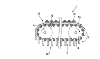
歯車Wは、架け渡しロッド4の長手方向に間隔を隔てて配置される2本のアーム18からなるアーム対19の上に載置されて搬送される。アーム対19は、搬送方向に複数設けられており、搬送方向において隣り合う2つのアーム対19は、一方のアーム対19をなす2つのアーム18間に、他方のアーム対19をなす2つのアーム18が配置されている。
The gear W is placed and conveyed on an arm pair 19 composed of two arms 18 arranged at intervals in the longitudinal direction of the bridge rod 4. A plurality of arm pairs 19 are provided in the transport direction, and two arm pairs 19 adjacent in the transport direction are two arms 18 forming the other arm pair 19 between two arms 18 forming one arm pair 19. 18 is arranged.
例えば、本実施形態のチェーン式搬送装置1にて、軸付の歯車Wに熱処理を施すために搬送する際には、図3に示すように、歯車Wを、交差方向において互いに隣り合う2つのアーム18に歯車Wが渡り、軸Waが、搬送方向に隣り合う架け渡しロッド4間に挿入されて鉛直に沿うように載せることができ、軸Waのような突出のあるワークでも、上記従来の課題を解消して、平面上に同一の姿勢で維持させることができる。このとき、歯車Wを渡らせて配置する2つのアーム18がアーム対19に相当し、アーム対19の間の空間Hは、ワークである歯車Wを、チェーン式搬送装置1に載せるときの目安となり、人手やロボットなどで整列して載せることができる。これにより、どの歯車Wも、処理される条件を均一にできるようになる。
For example, when the chain-type transport device 1 according to the present embodiment transports the shaft-equipped gear W for heat treatment, as shown in FIG. A gear W crosses over the arm 18 and the shaft Wa can be inserted between the bridging rods 4 adjacent to each other in the conveying direction so as to be placed along the vertical direction. The problem can be solved and maintained in the same posture on the plane. At this time, the two arms 18 arranged across the gear W correspond to the arm pair 19, and the space H between the arm pair 19 is a guideline for placing the gear W, which is a workpiece, on the chain type conveyance device 1. It can be placed by hand or robot. As a result, any gear W can be made to have uniform processing conditions.
駆動装置により駆動されて循環されるローラーチェーン3と共に移動する複数の架け渡しロッド4に設けられたアーム18上の歯車Wは、搬送されつつ加熱処理され、次工程の搬送装置等に移動される。
The gears W on the arms 18 provided on the plurality of spanning rods 4 that move together with the roller chain 3 that is driven and circulated by the driving device are heated while being transported, and are moved to the transport device or the like in the next process. .
図9に示すように、歯車Wが取り除かれたアーム18は、駆動装置と反対側に設けられているスプロケット15’により折り返されるローラーチェーン3とともに搬送方向と反対側に移動される際に、回動して架け渡しロッド4から垂れ下がりつつ移動する(図中、Rで示す)。そして、再び駆動側のスプロケット15によりレール2上に移動される際に、アーム18が回動しながら搬送方向における後方側に位置する架け渡しロッド4上に載置される。再び水平に配置されたアーム18上には、熱処理前の新たな歯車Wが載置されて搬送される。
As shown in FIG. 9, when the arm 18 from which the gear W has been removed is moved to the opposite side to the conveying direction together with the roller chain 3 turned back by the sprocket 15 'provided on the opposite side to the drive device, It moves and moves down from the bridge rod 4 (indicated by R in the figure). And when it moves on the rail 2 again by the drive side sprocket 15, the arm 18 is placed on the bridge rod 4 located on the rear side in the transport direction while rotating. A new gear W before the heat treatment is placed and transported on the arm 18 that is arranged horizontally again.
本実施形態のチェーン式搬送装置1によれば、互いに間隔を隔てて配置された一対のローラーチェーン3間に架け渡されて一対のローラーチェーン3とともに循環する複数の架け渡しロッド4に、熱処理される歯車Wが載置されるアーム18が設けられているので、歯車Wが載置される部位は、上下方向に開放されている。このチェーン式搬送装置1により歯車Wがヒーター16上を搬送されるので、効率よく熱処理することが可能である。また、歯車Wが載置される部位が上下方向に開放されていることにより、歯車Wが軸Waを備えていたとしても、軸Waを上下方向に向けて配置することにより、歯車Wをほぼ同じ姿勢にて配置することが可能である。このため、チェーン式搬送装置1上に載置された複数の歯車Wを、より均一に熱処理することが可能である。
According to the chain type conveying apparatus 1 of the present embodiment, the plurality of transfer rods 4 that are bridged between a pair of roller chains 3 that are spaced apart from each other and circulate together with the pair of roller chains 3 are heat-treated. Since the arm 18 on which the gear W is mounted is provided, the portion on which the gear W is mounted is opened in the vertical direction. Since the gear W is transported on the heater 16 by the chain transport device 1, heat treatment can be performed efficiently. Further, since the portion where the gear W is placed is opened in the vertical direction, even if the gear W is provided with the axis Wa, the gear W is substantially arranged by arranging the axis Wa in the vertical direction. It is possible to arrange with the same posture. For this reason, it is possible to heat-process the some gear W mounted on the chain type conveying apparatus 1 more uniformly.
また、一対のローラーチェーン3は、互いに対向する方向に突出された2本の軸部10が、架け渡しロッド4の両端部に挿入され、一方の端部が割りピン17により固定され、他方の端部が架け渡しロッド4の長手方向に相対移動可能に挿入されているので、熱処理の熱により架け渡しロッド4が伸長したとしても、また、伸長後再び収縮したとしても、ローラーチェーン3がスプロケット15から外れる、或いは、レール2等に押圧されて過大な負荷が作用することを防止することが可能である。
Further, in the pair of roller chains 3, two shaft portions 10 projecting in opposite directions are inserted into both end portions of the bridging rod 4, one end portion is fixed by the split pin 17, and the other Since the end portion is inserted so as to be relatively movable in the longitudinal direction of the bridging rod 4, even if the bridging rod 4 expands due to heat of heat treatment or contracts again after the expansion, the roller chain 3 is sprocketed. 15 or it is possible to prevent an excessive load from acting on the rail 2 or the like.
また、割りピン17とは反対側のローラーチェーン3を外せば、割りピン17を取り外すだけで、架け渡しロッド4を外せるので、歯車(ワーク)Wの形状によってアーム18の形状を変更した架け渡しロッド4に容易に交換することができる。
Also, if the roller chain 3 on the side opposite to the split pin 17 is removed, the transfer rod 4 can be removed simply by removing the split pin 17, so that the transfer is performed by changing the shape of the arm 18 depending on the shape of the gear (workpiece) W. The rod 4 can be easily replaced.
また、アーム18は、互いに異なる2本の架け渡しロッド4に渡って設けられているので、安定した状態で歯車Wを配置することが可能である。このとき、アーム18は、2本の架け渡しロッド4のうちの一方に取り付けられ、自由に回動するので、循環するローラーチェーン3をスプロケット15に滑らかに巻きつけることが可能である。
In addition, since the arm 18 is provided across two different bridge rods 4, the gear W can be disposed in a stable state. At this time, the arm 18 is attached to one of the two spanning rods 4 and freely rotates, so that the circulating roller chain 3 can be smoothly wound around the sprocket 15.
また、アーム18は、搬送方向における先行側の端が架け渡しロッド4に回動自在に取り付けられているので、レール2の下側にて架け渡しロッド4に垂れ下がっている状態から、スプロケット15によりレール2の上側に引き上げられるだけで、アーム18の載置支持端18bを搬送方向における後方側に位置する架け渡しロッド4上に配置することが可能である。
Since the arm 18 is pivotally attached to the bridge rod 4 at the leading end in the conveying direction, the arm 18 is suspended from the bridge rod 4 below the rail 2 by the sprocket 15. It is possible to dispose the mounting support end 18b of the arm 18 on the bridge rod 4 located on the rear side in the transport direction simply by pulling up to the upper side of the rail 2.
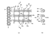
上記実施形態においては、アーム18の一方の端部を回動自在に支持し、他端部を隣り合う架け渡しロッド4上に載置する例について説明したが、レール2の下側でアーム18が垂れ下がることが邪魔になる場合には、レール2の下側全域にガイド22を設けたり、図6に示すように、他端部側にアーム18の長手方向に相対移動可能な係合部21にて係合させて、垂れ下がらないようにしておいてもよい。この場合には、隣り合う2本の架け渡しロッド4からアーム18の両端部が離れることなく、ローラーチェーン3とともにスムーズに循環させることが可能である。
In the above-described embodiment, an example in which one end portion of the arm 18 is rotatably supported and the other end portion is placed on the adjacent spanning rod 4 has been described. In the case where it poses a hindrance, the guide 22 is provided in the entire lower side of the rail 2, or the engaging portion 21 that is relatively movable in the longitudinal direction of the arm 18 on the other end side as shown in FIG. It is also possible to engage with each other so as not to hang down. In this case, both ends of the arm 18 can be smoothly circulated together with the roller chain 3 without leaving the two adjacent connecting rods 4.
なお、補助パイプ23は、熱処理炉内で加熱・蓄熱され、歯車(ワーク)Wに、下部から輻射熱を与えて歯車Wを均一に加熱することができるという効果があり、ワークWの形状や温度分布によって、太さの違うものと交換しても良い。
The auxiliary pipe 23 is heated and stored in a heat treatment furnace, and has an effect that the gear W can be heated uniformly by applying radiant heat to the gear (work) W from below. Depending on the distribution, it may be replaced with a different thickness.
また、図7に示すように、補助パイプ23は、設置しなくても良く、このようにすれば、空間Hの面積を広くすることができ、突出部Waの面積が広くて長いワークWであっても、平面上に同じ姿勢で配置することができる。
Further, as shown in FIG. 7, the auxiliary pipe 23 does not need to be installed, and in this way, the area of the space H can be widened, and the projecting portion Wa has a large area and a long work W. Even if it exists, it can arrange | position with the same attitude | position on a plane.
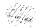
また、上記実施形態においては、歯車Wが載置される一対のアーム18が連結されていない例について説明したが、図10に示すように、対をなすアームが回動支持端及び載置支持端にて連結材24で連結されていても構わない。この場合には、歯車Wの載置をより安定させることが可能である。また、例えば、ロボットなどを使用して歯車をアーム上に載置する際に、歯車Wを載置する位置を、一対のアーム、連結部、及び架け渡しロッドが形成する矩形状の部位として認識させることが可能となり、歯車等のワークを載置する工程の自動化が容易となる。
In the above-described embodiment, the example in which the pair of arms 18 on which the gear W is placed is not connected has been described. However, as shown in FIG. 10, the pair of arms has a rotation support end and a placement support. You may connect with the connection material 24 by the edge. In this case, it is possible to further stabilize the placement of the gear W. Further, for example, when a gear is placed on an arm using a robot or the like, the position where the gear W is placed is recognized as a rectangular portion formed by the pair of arms, the connecting portion, and the bridge rod. This makes it easy to automate the process of placing a workpiece such as a gear.
また、上記実施形態は、本発明の理解を容易にするためのものであり、本発明を限定して解釈するためのものではない。本発明は、その趣旨を逸脱することなく、変更、改良され得ると共に、本発明にはその等価物が含まれることはいうまでもない。
Further, the above embodiment is for facilitating the understanding of the present invention, and is not for limiting the interpretation of the present invention. The present invention can be changed and improved without departing from the gist thereof, and it is needless to say that the present invention includes equivalents thereof.
1 チェーン式搬送装置
2 レール
3 ローラーチェーン
4 架け渡しロッド
5 内プレート
6 ローラー
7 ブッシュ
8 貫通孔
9 内リンク
10 軸部
11 外プレート
12 外リンク
13 台座
14 レール体
15,15’ スプロケット
16 溝
17 割りピン
18 アーム
18a 回動支持端
18b 載置支持端
18c,18d 半割りしたアーム
19 アーム対
20,20a,20b,20c 近接部
21 係合部
22 ガイド
23 補助パイプ
24 連結材
G 間隙
H 空間
S 隙間
W 歯車
Wa 軸 DESCRIPTION OFSYMBOLS 1 Chain type conveying apparatus 2 Rail 3 Roller chain 4 Transfer rod 5 Inner plate 6 Roller 7 Bush 8 Through-hole 9 Inner link 10 Shaft part 11 Outer plate 12 Outer link 13 Base 14 Rail body 15, 15 'Sprocket 16 Groove 17 Split Pin 18 Arm 18a Rotation support end 18b Placement support end 18c, 18d Half split arm 19 Arm pair 20, 20a, 20b, 20c Proximity part 21 Engagement part 22 Guide 23 Auxiliary pipe 24 Connecting material G Gap H Space S Gap W gear Wa shaft
2 レール
3 ローラーチェーン
4 架け渡しロッド
5 内プレート
6 ローラー
7 ブッシュ
8 貫通孔
9 内リンク
10 軸部
11 外プレート
12 外リンク
13 台座
14 レール体
15,15’ スプロケット
16 溝
17 割りピン
18 アーム
18a 回動支持端
18b 載置支持端
18c,18d 半割りしたアーム
19 アーム対
20,20a,20b,20c 近接部
21 係合部
22 ガイド
23 補助パイプ
24 連結材
G 間隙
H 空間
S 隙間
W 歯車
Wa 軸 DESCRIPTION OF
Claims (6)
- 熱処理するワークを搬送するチェーン式搬送装置であって、
搬送方向に沿うとともに互いに間隔を隔てて配置された一対のチェーンと、
前記一対のチェーン間に架け渡されて前記一対のチェーンとともに循環する複数の架け渡しロッドと、
前記架け渡しロッドに前記搬送方向に沿って設けられ前記ワークが載置される複数のアームと、
を有していることを特徴とするチェーン式搬送装置。 A chain type conveying device for conveying a workpiece to be heat-treated,
A pair of chains arranged along the conveying direction and spaced apart from each other;
A plurality of spanning rods that are spanned between the pair of chains and circulate with the pair of chains;
A plurality of arms provided along the transport direction on the bridge rod and on which the workpiece is placed;
A chain type conveying apparatus characterized by comprising: - 前記一対のチェーンは、互いに対向する方向に突出された突出ロッドを各々有し、
前記架け渡しロッドは、両端部に前記突出ロッドが挿入される挿入部を有し、一方の端部が前記突出ロッドに固定され、他方の端部は前記架け渡しロッドの長手方向に相対移動可能に挿入されていることを特徴とする請求項1に記載のチェーン式搬送装置。 Each of the pair of chains has protruding rods protruding in directions facing each other,
The spanning rod has an insertion portion into which the projecting rod is inserted at both ends, one end is fixed to the projecting rod, and the other end is relatively movable in the longitudinal direction of the spanning rod The chain type conveying device according to claim 1, wherein the chain type conveying device is inserted into the chain type conveying device. - 前記アームは、互いに異なる2本の前記架け渡しロッドに渡って設けられ、一方の前記架け渡しロッドに取り付けられ、他方の前記架け渡しロッド上に載置されることを特徴とする請求項1または請求項2に記載のチェーン式搬送装置。 2. The arm according to claim 1, wherein the arm is provided across two different bridging rods, is attached to one of the bridging rods, and is placed on the other bridging rod. The chain type conveying apparatus according to claim 2.
- 前記アームは、回動支持端を有し、当該回動支持端が前記架け渡しロッドに回動自在に取り付けられていることを特徴とする請求項3に記載のチェーン式搬送装置。 The chain-type transport device according to claim 3, wherein the arm has a rotation support end, and the rotation support end is rotatably attached to the bridge rod.
- 前記アームは、前記他方の架け渡しロッドと、搬送方向において相対移動可能に載せられていることを特徴とする請求項3に記載のチェーン式搬送装置。 The chain type conveying device according to claim 3, wherein the arm is mounted on the other bridge rod so as to be relatively movable in the conveying direction.
- 前記架け渡しロッドの長手方向に間隔を隔てて配置され単一の前記ワークが載置される2つの前記アームからなるアーム対が、前記搬送方向に複数設けられており、
搬送方向において隣り合う2つの前記アーム対は、一方の前記アーム対をなす2つの前記アーム間に、他方の前記アーム対をなす2つのアームが配置されることを特徴とする請求項1~5のいずれかに記載のチェーン式搬送装置。 A plurality of arm pairs each including two arms on which a single workpiece is placed and spaced apart in the longitudinal direction of the spanning rod are provided in the transport direction;
The two arm pairs adjacent to each other in the transport direction are arranged such that two arms forming the other arm pair are arranged between the two arms forming one arm pair. The chain type conveying apparatus according to any one of the above.
Applications Claiming Priority (2)
| Application Number | Priority Date | Filing Date | Title |
|---|---|---|---|
| JP2016190751A JP2018052685A (en) | 2016-09-29 | 2016-09-29 | Chain-type conveying device |
| JP2016-190751 | 2016-09-29 |
Publications (1)
| Publication Number | Publication Date |
|---|---|
| WO2018061325A1 true WO2018061325A1 (en) | 2018-04-05 |
Family
ID=61759381
Family Applications (1)
| Application Number | Title | Priority Date | Filing Date |
|---|---|---|---|
| PCT/JP2017/021092 WO2018061325A1 (en) | 2016-09-29 | 2017-06-07 | Chain type transport device |
Country Status (2)
| Country | Link |
|---|---|
| JP (1) | JP2018052685A (en) |
| WO (1) | WO2018061325A1 (en) |
Cited By (2)
| Publication number | Priority date | Publication date | Assignee | Title |
|---|---|---|---|---|
| WO2021235012A1 (en) * | 2020-05-22 | 2021-11-25 | 東洋製罐グループエンジニアリング株式会社 | Container transport mechanism |
| JP2021183538A (en) * | 2020-05-22 | 2021-12-02 | 東洋製罐グループエンジニアリング株式会社 | Container conveyance mechanism |
Citations (5)
| Publication number | Priority date | Publication date | Assignee | Title |
|---|---|---|---|---|
| JPS514083U (en) * | 1974-06-25 | 1976-01-13 | ||
| JPS5220068U (en) * | 1975-07-31 | 1977-02-12 | ||
| JPH03113310U (en) * | 1990-03-06 | 1991-11-19 | ||
| US20100282577A1 (en) * | 2009-05-08 | 2010-11-11 | Alit S.R.L. | Link of a side chain for conveyor belts |
| JP2013245106A (en) * | 2012-05-29 | 2013-12-09 | Maruyasu Kikai Kk | Hook type carrying conveyor |
-
2016
- 2016-09-29 JP JP2016190751A patent/JP2018052685A/en active Pending
-
2017
- 2017-06-07 WO PCT/JP2017/021092 patent/WO2018061325A1/en active Application Filing
Patent Citations (5)
| Publication number | Priority date | Publication date | Assignee | Title |
|---|---|---|---|---|
| JPS514083U (en) * | 1974-06-25 | 1976-01-13 | ||
| JPS5220068U (en) * | 1975-07-31 | 1977-02-12 | ||
| JPH03113310U (en) * | 1990-03-06 | 1991-11-19 | ||
| US20100282577A1 (en) * | 2009-05-08 | 2010-11-11 | Alit S.R.L. | Link of a side chain for conveyor belts |
| JP2013245106A (en) * | 2012-05-29 | 2013-12-09 | Maruyasu Kikai Kk | Hook type carrying conveyor |
Cited By (3)
| Publication number | Priority date | Publication date | Assignee | Title |
|---|---|---|---|---|
| WO2021235012A1 (en) * | 2020-05-22 | 2021-11-25 | 東洋製罐グループエンジニアリング株式会社 | Container transport mechanism |
| JP2021183538A (en) * | 2020-05-22 | 2021-12-02 | 東洋製罐グループエンジニアリング株式会社 | Container conveyance mechanism |
| JP7394700B2 (en) | 2020-05-22 | 2023-12-08 | 東洋製罐グループエンジニアリング株式会社 | Container transport mechanism |
Also Published As
| Publication number | Publication date |
|---|---|
| JP2018052685A (en) | 2018-04-05 |
Similar Documents
| Publication | Publication Date | Title |
|---|---|---|
| US10925436B2 (en) | Roller conveyor oven for heating while rotating and conveying a multiplicity of cylindrical food items thereon | |
| WO2018061325A1 (en) | Chain type transport device | |
| US3880276A (en) | Conveyor chain | |
| JP6214620B2 (en) | Sheet material drawing machine | |
| KR101169709B1 (en) | Apparatus for heat treating steel pipe | |
| US20150000154A1 (en) | Dryer having woven wire belt conveyor system | |
| EP0960863B1 (en) | Furnace for the continuous heat treatment of glass containers | |
| JPS6210935B2 (en) | ||
| KR100670158B1 (en) | High frequency - heat treatment apparatus of horizontally feeding type | |
| JP6933875B2 (en) | Food roasting device | |
| JP5762679B2 (en) | Hot air drying equipment for food dough | |
| JPH07148540A (en) | Work cooling device in forging equipment | |
| JP2008150188A (en) | Wire-mesh conveyor belt and conveyance machine for food manufacturing device | |
| JP4477473B2 (en) | Conveying machine for food manufacturing apparatus, hot air drying apparatus and baking apparatus using the conveying machine | |
| JP4970135B2 (en) | Food processing apparatus and food processing method | |
| JP6643893B2 (en) | Nori grilling equipment | |
| CN100444707C (en) | Heating device | |
| JP2004203551A5 (en) | ||
| JP2018052685A5 (en) | ||
| JP2006131357A5 (en) | ||
| KR101093234B1 (en) | Apparatus for quenching | |
| JP7118637B2 (en) | High frequency induction heating device | |
| JP2008185231A (en) | Roller hearth type heat treatment furnace | |
| JPH10250816A (en) | Net conveyor | |
| JP6759562B2 (en) | Work transfer device |
Legal Events
| Date | Code | Title | Description |
|---|---|---|---|
| DPE2 | Request for preliminary examination filed before expiration of 19th month from priority date (pct application filed from 20040101) | ||
| 121 | Ep: the epo has been informed by wipo that ep was designated in this application |
Ref document number: 17855284 Country of ref document: EP Kind code of ref document: A1 |
|
| NENP | Non-entry into the national phase |
Ref country code: DE |
|
| 122 | Ep: pct application non-entry in european phase |
Ref document number: 17855284 Country of ref document: EP Kind code of ref document: A1 |