JP6502633B2 - Substrate processing method and substrate processing apparatus - Google Patents
Substrate processing method and substrate processing apparatus Download PDFInfo
- Publication number
- JP6502633B2 JP6502633B2 JP2014170205A JP2014170205A JP6502633B2 JP 6502633 B2 JP6502633 B2 JP 6502633B2 JP 2014170205 A JP2014170205 A JP 2014170205A JP 2014170205 A JP2014170205 A JP 2014170205A JP 6502633 B2 JP6502633 B2 JP 6502633B2
- Authority
- JP
- Japan
- Prior art keywords
- substrate
- etching
- phosphoric acid
- solution
- hydrofluoric acid
- Prior art date
- Legal status (The legal status is an assumption and is not a legal conclusion. Google has not performed a legal analysis and makes no representation as to the accuracy of the status listed.)
- Active
Links
Images


Classifications
-
- H—ELECTRICITY
- H10—SEMICONDUCTOR DEVICES; ELECTRIC SOLID-STATE DEVICES NOT OTHERWISE PROVIDED FOR
- H10P—GENERIC PROCESSES OR APPARATUS FOR THE MANUFACTURE OR TREATMENT OF DEVICES COVERED BY CLASS H10
- H10P50/00—Etching of wafers, substrates or parts of devices
- H10P50/60—Wet etching
- H10P50/64—Wet etching of semiconductor materials
- H10P50/642—Chemical etching
-
- H—ELECTRICITY
- H10—SEMICONDUCTOR DEVICES; ELECTRIC SOLID-STATE DEVICES NOT OTHERWISE PROVIDED FOR
- H10P—GENERIC PROCESSES OR APPARATUS FOR THE MANUFACTURE OR TREATMENT OF DEVICES COVERED BY CLASS H10
- H10P50/00—Etching of wafers, substrates or parts of devices
- H10P50/20—Dry etching; Plasma etching; Reactive-ion etching
- H10P50/28—Dry etching; Plasma etching; Reactive-ion etching of insulating materials
- H10P50/282—Dry etching; Plasma etching; Reactive-ion etching of insulating materials of inorganic materials
- H10P50/283—Dry etching; Plasma etching; Reactive-ion etching of insulating materials of inorganic materials by chemical means
-
- H—ELECTRICITY
- H10—SEMICONDUCTOR DEVICES; ELECTRIC SOLID-STATE DEVICES NOT OTHERWISE PROVIDED FOR
- H10P—GENERIC PROCESSES OR APPARATUS FOR THE MANUFACTURE OR TREATMENT OF DEVICES COVERED BY CLASS H10
- H10P14/00—Formation of materials, e.g. in the shape of layers or pillars
- H10P14/20—Formation of materials, e.g. in the shape of layers or pillars of semiconductor materials
- H10P14/34—Deposited materials, e.g. layers
- H10P14/3402—Deposited materials, e.g. layers characterised by the chemical composition
- H10P14/3414—Deposited materials, e.g. layers characterised by the chemical composition being group IIIA-VIA materials
- H10P14/3416—Nitrides
-
- H—ELECTRICITY
- H10—SEMICONDUCTOR DEVICES; ELECTRIC SOLID-STATE DEVICES NOT OTHERWISE PROVIDED FOR
- H10P—GENERIC PROCESSES OR APPARATUS FOR THE MANUFACTURE OR TREATMENT OF DEVICES COVERED BY CLASS H10
- H10P72/00—Handling or holding of wafers, substrates or devices during manufacture or treatment thereof
- H10P72/04—Apparatus for manufacture or treatment
- H10P72/0402—Apparatus for fluid treatment
- H10P72/0418—Apparatus for fluid treatment for etching
- H10P72/0422—Apparatus for fluid treatment for etching for wet etching
- H10P72/0424—Apparatus for fluid treatment for etching for wet etching using mainly spraying means, e.g. nozzles
-
- H—ELECTRICITY
- H10—SEMICONDUCTOR DEVICES; ELECTRIC SOLID-STATE DEVICES NOT OTHERWISE PROVIDED FOR
- H10P—GENERIC PROCESSES OR APPARATUS FOR THE MANUFACTURE OR TREATMENT OF DEVICES COVERED BY CLASS H10
- H10P72/00—Handling or holding of wafers, substrates or devices during manufacture or treatment thereof
- H10P72/70—Handling or holding of wafers, substrates or devices during manufacture or treatment thereof for supporting or gripping
- H10P72/76—Handling or holding of wafers, substrates or devices during manufacture or treatment thereof for supporting or gripping using mechanical means, e.g. clamps or pinches
- H10P72/7604—Handling or holding of wafers, substrates or devices during manufacture or treatment thereof for supporting or gripping using mechanical means, e.g. clamps or pinches the wafers being placed on a susceptor, stage or support
- H10P72/7618—Handling or holding of wafers, substrates or devices during manufacture or treatment thereof for supporting or gripping using mechanical means, e.g. clamps or pinches the wafers being placed on a susceptor, stage or support characterised by a movable susceptor, stage or support, others than those only rotating on their own vertical axis, e.g. susceptors on a rotating carrousel
-
- H—ELECTRICITY
- H10—SEMICONDUCTOR DEVICES; ELECTRIC SOLID-STATE DEVICES NOT OTHERWISE PROVIDED FOR
- H10P—GENERIC PROCESSES OR APPARATUS FOR THE MANUFACTURE OR TREATMENT OF DEVICES COVERED BY CLASS H10
- H10P95/00—Generic processes or apparatus for manufacture or treatments not covered by the other groups of this subclass
- H10P95/90—Thermal treatments, e.g. annealing or sintering
Landscapes
- Weting (AREA)
- Chemical & Material Sciences (AREA)
- Chemical Kinetics & Catalysis (AREA)
- General Chemical & Material Sciences (AREA)
- Cleaning Or Drying Semiconductors (AREA)
Description
本件発明は、窒化膜が形成されたシリコン製の基板をリン酸を含むエッチング液により処理する基板処理方法及び装置に関する。 The present invention relates to a substrate processing method and apparatus for processing a silicon substrate on which a nitride film is formed with an etching solution containing phosphoric acid.
従来、窒化膜(Si3N4)及び酸化膜(SiO2)が形成されたシリコン製の半導体ウェーハ(基板)をリン酸(H3PO4)を含むエッチング液により処理する基板処理方法が提案されている(特許文献1参照)。この基板処理方法では、エッチング槽に溜められたリン酸(H3PO4)を含むエッチング液中に複数の半導体ウェーハを投入して、その複数の半導体ウェーハのそれぞれに対するエッチング処理が一括的に行われる。このエッチング処理ではエッチング液中のリン酸が触媒として作用して半導体ウェーハの窒化膜(Si3N4)が除去される。 Conventionally, a substrate processing method has been proposed in which a silicon semiconductor wafer (substrate) on which a nitride film (Si 3 N 4 ) and an oxide film (SiO 2 ) are formed is treated with an etching solution containing phosphoric acid (H 3 PO 4 ) (See Patent Document 1). In this substrate processing method, a plurality of semiconductor wafers are put into an etching solution containing phosphoric acid (H 3 PO 4 ) stored in an etching tank, and etching processes for each of the plurality of semiconductor wafers are performed collectively. It will be. In this etching process, phosphoric acid in the etching solution acts as a catalyst to remove the nitride film (Si 3 N 4 ) of the semiconductor wafer.
そして、前記エッチング処理が行われてエッチング処理槽内に残った使用済みエッチング液が受け槽を介して再生装置の処理槽に移される。使用済みエッチング液が溜められた処理槽内に、前記使用済みエッチング液の量に対して適量のフッ酸溶液(HF)が添加される。処理槽内では、比較的高温の所定の温度環境のもとで、前記エッチング処理により除去された窒化物に基づく成分を含む使用済みエッチング液とフッ酸溶液(HF)とが混ざり合って反応し、リン酸(H3PO4)が再生される。この再生されたリン酸(H3PO4)が前記エッチング処理に使用されるべきエッチング液に戻される。 Then, the etching treatment is performed, and the used etching solution remaining in the etching treatment tank is transferred to the treatment tank of the regenerating apparatus through the receiving tank. An appropriate amount of hydrofluoric acid solution (HF) is added to the amount of the used etching solution in the processing bath in which the used etching solution is stored. In the processing bath, under a relatively high temperature and predetermined temperature environment, the used etching solution containing the nitride-based component removed by the etching process mixes with the hydrofluoric acid solution (HF) to react. , Phosphoric acid (H 3 PO 4 ) is regenerated. The regenerated phosphoric acid (H 3 PO 4 ) is returned to the etchant to be used for the etching process.
このような基板処理方法によれば、エッチング処理後に残る使用済みエッチング液からリン酸が再生され、そのリン酸がエッチング処理に使用されるべきエッチング液に戻されるので、リン酸を有効に利用しつつ、窒化膜を除去するための半導体ウェーハに対するエッチング処理を継続して行うことができる。 According to such a substrate processing method, since phosphoric acid is regenerated from the used etching solution remaining after the etching process and the phosphoric acid is returned to the etching solution to be used for the etching process, phosphoric acid is effectively used. At the same time, the etching process can be continued on the semiconductor wafer for removing the nitride film.
しかしながら、上述した基板処理方法では、多くの基板に対するエッチング処理を一括で行うための大きなエッチング槽が必要であり、また、そのような多くの基板に対するエッチング処理を一括して行うほどの多くの量の使用済みエッチング液を処理槽に溜めてその処理槽にフッ酸溶液を適量添加し、比較的高い温度の所定の温度環境のもとで、使用済みエッチング液とフッ酸溶液とを反応させるので、多くの量の使用済みエッチング液とそれに対して多くの量のフッ酸溶液を所定の温度環境に保つための設備が大がかりになる。また、1回で再生されるリン酸の量は多くなるものの、処理槽内において多くの量の使用済みエッチング液全体とフッ酸溶液全体とが効率よく反応し得るように混ざるまでに比較的長い時間を要し、必ずしも効率的にリン酸の再生ができるものとはいえない。 However, the above-described substrate processing method requires a large etching bath for performing etching on a large number of substrates at one time, and a large amount of etching treatment on such a large number of substrates at one time. The spent etching solution is stored in a processing bath, and a proper amount of hydrofluoric acid solution is added to the processing bath, and the spent etching solution and the hydrofluoric acid solution are reacted under a relatively high temperature and a predetermined temperature environment. The equipment for maintaining a large amount of used etching solution and the large amount of hydrofluoric acid solution in a predetermined temperature environment is bulky. In addition, although the amount of phosphoric acid regenerated at one time increases, it is relatively long before mixing so that a large amount of the whole used etching solution and the whole hydrofluoric acid solution can efficiently react in the processing tank. It takes time, and it can not always be said that phosphoric acid can be regenerated efficiently.
本発明はこのような事情に鑑みてなされたもので、できる限り大きな設備を用いることなく、エッチング処理とともに、そのエッチング処理に戻すことのできるリン酸をより効率的に再生することのできる基板処理方法及び基板処理装置を提供するものである。 The present invention has been made in view of such circumstances, and it is possible to more efficiently regenerate phosphoric acid that can be returned to the etching process together with the etching process without using as large equipment as possible. A method and a substrate processing apparatus are provided.
本発明に係る基板処理方法は、
基板を回転させる基板スピン機構と、前記基板スピン機構によって回転される前記基板の表面にエッチング液を供給するエッチング液供給機構と、前記回転する基板の表面に供給される前記エッチング液が前記基板の表面から飛散した後の使用済みエッチング液を溜める液溜め部と、を有するエッチング処理部を用いて、窒化膜が形成されたシリコン製の基板をリン酸を含むエッチング液により処理する基板処理方法であって、
1枚ずつ供給される前記基板のそれぞれを前記基板スピン機構で回転させ、前記回転する前記基板に前記エッチング液供給機構から前記エッチング液を供給して前記基板に対するエッチング処理を行い、窒化膜を除去するエッチング処理ステップと、
前記エッチング処理ステップにて1枚ずつ所定枚数の前記基板を処理した分の使用済みエッチング液と、フッ酸溶液とを、前記液溜め部にて混合してリン酸を再生するリン酸再生ステップと、
前記リン酸再生ステップにより得られたリン酸を前記エッチング処理ステップにて使用されるべきエッチング液に戻すリン酸回収ステップとを有し、
前記リン酸再生ステップは、前記使用済みエッチング液と前記フッ酸溶液とを、それらのうちの少なくともいずれか一方を霧状または蒸気状にして混合する構成となる。
The substrate processing method according to the present invention is
A substrate spin mechanism for rotating a substrate, an etchant supply mechanism for supplying an etchant to the surface of the substrate rotated by the substrate spin mechanism, and the etchant supplied to the surface of the rotating substrate are for the substrate. A substrate processing method for processing a silicon substrate on which a nitride film is formed with an etching solution containing phosphoric acid using an etching processing unit having a liquid storage unit for storing used etching solution after scattering from the surface. There,
Each of the substrates supplied one by one is rotated by the substrate spin mechanism, and the etching solution is supplied to the rotating substrate from the etchant supply mechanism to etch the substrate, thereby removing the nitride film. Etching process steps,
A phosphoric acid regenerating step of regenerating phosphoric acid by mixing a used etching solution for treating a predetermined number of the substrates one by one in the etching step and a hydrofluoric acid solution in the liquid reservoir ; ,
And a phosphoric acid recovery step of returning the phosphoric acid obtained by the phosphoric acid regeneration step to the etching solution to be used in the etching step.
The phosphoric acid regeneration step is configured to mix the used etching solution and the hydrofluoric acid solution in a form of mist or vapor of at least one of them.
本発明に係る基板処理装置は、
窒化膜が形成されたシリコン製の基板をリン酸を含むエッチング液により処理する基板処理装置であって、
1枚ずつ供給される基板のそれぞれを回転させる基板スピン機構と、前記基板スピン機構によって回転される前記基板の表面に前記エッチング液を供給するエッチング液供給機構と、前記回転する基板の表面に供給される前記エッチング液が前記基板の表面から飛散した後の使用済みエッチング液を溜める液溜め部とを有し、前記基板に前記エッチング液を供給して前記基板に対するエッチング処理を行い、窒化膜を除去するエッチング処理部と、
前記液溜め部にフッ酸溶液を供給するフッ酸供給機構を有し、前記使用済みエッチング液と、前記フッ酸溶液とを、前記液溜め部にて混合してリン酸を再生するリン酸再生部と、
前記リン酸再生部により得られたリン酸を前記エッチング処理部にて使用されるべきエッチング液に戻すリン酸回収部と、
を有し、
前記リン酸再生部は、前記使用済みエッチング液と前記フッ酸溶液とを、それらのうちの少なくともいずれか一方を霧状または蒸気状にして混合する構成となる。
The substrate processing apparatus according to the present invention is
A substrate processing apparatus for processing a silicon substrate on which a nitride film is formed with an etching solution containing phosphoric acid,
A substrate spin mechanism for rotating each of the substrates supplied one by one, an etching liquid supply mechanism for supplying the etching solution to the surface of the substrate rotated by the substrate spin mechanism, and a supply to the surface of the rotating substrate And the liquid storage portion for storing used etching liquid after the etching liquid is scattered from the surface of the substrate, the etching liquid is supplied to the substrate to perform etching processing on the substrate, and a nitride film is formed. An etched portion to be removed,
A hydrofluoric acid supply mechanism for supplying hydrofluoric acid solution to the liquid reservoir, wherein the spent etching solution, and the hydrofluoric acid solution and mixed to phosphoric acid regeneration to regenerate phosphoric acid in the liquid reservoir Department,
A phosphoric acid recovery unit for returning the phosphoric acid obtained by the phosphoric acid regeneration unit to an etching solution to be used in the etching processing unit ;
Have
The phosphoric acid regeneration unit is configured to mix the used etching solution and the hydrofluoric acid solution in a form of mist or vapor of at least one of them.
本発明に係る基板処理方法及び基板処理装置によれば、できる限り大きな設備を用いることなく、エッチング処理とともに、そのエッチング処理に戻すことのできるリン酸をより効率的に再生することができる。 According to the substrate processing method and the substrate processing apparatus according to the present invention, it is possible to more efficiently regenerate the phosphoric acid that can be returned to the etching process together with the etching process without using as large equipment as possible.
以下、本発明の実施の形態について図面を用いて説明する。 Hereinafter, embodiments of the present invention will be described using the drawings.
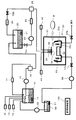
本発明の第1の実施の形態に係る基板処理装置は、図1に示すように構成される。 The substrate processing apparatus according to the first embodiment of the present invention is configured as shown in FIG.
図1において、基板処理装置は、エッチング液生成槽10、エッチング液貯留槽20、スピン処理ユニット30(エッチング処理部、リン酸再生部)、及びリン酸回収槽50(リン酸回収部)を有している。また、基板処理装置は、リン酸供給部12、水供給部13及びシリカ供給部14を有している。リン酸供給部12が所定濃度のリン酸溶液(H3PO4)を、水供給部13が純水(H2O)を、シリカ供給部14がコロイダルシリカ(SiO2)を、それぞれエッチング液生成槽10に供給する。エッチング液生成槽10にはヒータユニット11が設けられている。エッチング液生成槽10において、リン酸供給部12、水供給部13及びシリカ供給部14からそれぞれ適量供給されるリン酸溶液(H3PO4)、純水(H2O)及びコロイダルシリカ(SiO2)が混合され、ヒータユニット11による加熱によって所定の温度に維持される。所定の温度環境のもとでリン酸溶液(H3PO4)、純水(H2O)及びコロイダルシリカ(SiO2)が混合されて、リン酸及びシリコン成分を含むエッチング液が生成される。
In FIG. 1, the substrate processing apparatus has an etching
なお、シリカ供給部14から適量のコロイダルシリカ(SiO2)をエッチング液(リン酸溶液)に添加してエッチング液中のシリコン濃度を調整することにより、エッチング処理される半導体ウェーハに形成された窒化膜(Si3N4)と酸化膜(SiO2)との選択比を所定範囲に維持するようにしている。
The silicon nitride formed on the semiconductor wafer to be etched by adding an appropriate amount of colloidal silica (SiO 2 ) to the etching solution (phosphoric acid solution) from the
エッチング液生成槽10に対して循環経路が設けられ、その循環経路中に、ポンプ15、切替え弁16及び濃度検出器17が設けられている。この循環経路には更にヒータ(図示略)が設けられており、ポンプ15の動作によって、エッチング液生成槽10内のエッチング液が所定温度に維持された状態で切替え弁16及び濃度検出器17を介してエッチング液生成槽10に戻される。このようなエッチング液の循環により、エッチング液生成槽10内では、前記リン酸溶液(H3PO4)、純水(H2O)及びコロイダルシリカ(SiO2)が撹拌混合される。また、循環経路中に設けられた濃度検出器17による濃度検出情報に基づいて、生成されるエッチング液中のリン酸濃度が管理制御装置100によって監視される。切替え弁16は、前記循環経路と、エッチング液生成槽10からエッチング液貯留槽20への経路とを切り換える。切替え弁16によってエッチング液貯留槽20側の経路に切り替えられた状態でのポンプ15の動作によって、エッチング液生成槽10で生成されるエッチング液がエッチング液貯留槽20に供給されて溜められる。
A circulation path is provided for the etching
エッチング液貯留槽20には、ヒータユニット21が設けられ、エッチング液生成槽10から供給されて溜められたエッチング液が所定温度に維持される。エッチング液貯留槽20に対して循環経路が設けられている。この循環経路中には、開閉弁22a、ポンプ23、流量計24、切替え弁25、開閉弁22b及び冷却器26が設けられている。また、図示されてはいないが、循環経路のポンプ23と切替え弁25との間の経路部分にはヒータが設けられている。開閉弁22a,22bが開放された状態で、エッチング液貯留槽20に所定温度に維持されつつ溜められたエッチング液が、ポンプ23の動作により、循環経路(流量計24、切替え弁25、冷却器26)を通ってエッチング液貯留槽20に戻される。このようなエッチング液の循環により、エッチング液貯留槽20に溜められるエッチング液の温度及び濃度が一定条件に調整される。切替え弁25は、前記循環経路と、エッチング液貯留槽20からスピン処理ユニット30への経路とを切り換える。切替え弁25によってスピン処理ユニット30側の経路に切り替えられた状態でのポンプ23の動作によって、エッチング液貯留槽20に溜められたエッチング液がスピン処理ユニット30に供給される。
A
スピン処理ユニット30(エッチング処理部、リン酸再生部)は処理室31を有し、処理室31内に、半導体ウェーハWを回転させる基板スピン機構32が設けられるとともに、基板スピン機構32に対向するよう配置されたエッチング液噴出ノズル34(エッチング液供給機構)、リンス液噴出ノズル35及びフッ酸噴出ノズル36が設けられている。また、処理室31内に、基板スピン機構32の周囲に配置されるようにセパレートカップ機構33(液溜め部)が設けられている。セパレートカップ機構33は、内側液溜めカップ33c及びその外側に配置された外側液溜めカップ33aを有し、内側液溜めカップ33cと外側液溜めカップ33aとの境界部にセパレータ33bが設けられている。セパレータ33bは、アクチュエータ(図示略)によって所定の範囲内において上昇動及び下降動を行う。エッチング液噴出ノズル34には、前述したエッチング液貯留槽20から切替え弁25を介してスピン処理ユニット30側に延びる経路が接続されている。また、基板処理装置は、リンス液供給部41及びフッ酸供給部42を有しており、リンス液供給部41からリンス液(例えば、純水)がリンス液噴出ノズル35に供給され、フッ酸供給部42から所定濃度のフッ酸溶液(HF)がフッ酸噴出ノズル36(フッ酸供給機構)に供給される。
The spin processing unit 30 (etching processing unit, phosphoric acid regenerating unit) has a
内側液溜めカップ33cから延びる経路が開閉弁37a及びポンプ38を介してリン酸回収槽50に至っている。また、外側液溜めカップ33aから延びる経路が開閉弁37bを介して廃液槽(図示略)に至っている。
A path extending from the inner
後述するようなリン酸再生の処理によりスピン処理ユニット30(リン酸再生部)の内側液溜めカップ33cに溜まったリン酸溶液(H3PO4)が、ポンプ38の動作により開閉弁37aを介してリン酸回収槽50に供給される。リン酸回収槽50にはヒータユニット51が設けられており、リン酸回収槽50に溜められたリン酸溶液が所定温度に維持される。リン酸回収槽50からエッチング液生成槽10にポンプ52を介して経路が延びており、ポンプ52の動作によって、リン酸回収槽50からリン酸溶液がその経路を通ってエッチング液生成槽10に戻される。
The phosphoric acid solution (H 3 PO 4 ) accumulated in the inner
なお、前述したようなエッチング液の温度、流量、濃度等の管理とともに、各ポンプ、各種弁、各切替え弁、各種ヒータの動作、スピン処理ユニット30の動作及びスピン処理ユニット30に対する半導体ウェーハWの供給及び排出を行う機構等の各部の動作は、管理制御装置100によって制御される。
In addition to managing the temperature, flow rate, and concentration of the etching solution as described above, the operation of each pump, various valves, each switching valve, various heaters, operation of
上述した基板処理装置では、管理制御装置100での管理及び制御のもと、次のようにして半導体ウェーハWに対する処理が行われる。
In the substrate processing apparatus described above, processing on the semiconductor wafer W is performed as follows, under management and control in the
エッチング液生成槽10においてリン酸溶液(H3PO4)、純水(H2O)及びコロイダルシリカ(SiO2)が混ざり合って生成されるエッチング液が、高い温度(例えば、160℃程度)に調整されつつ、所定のタイミングでエッチング液貯留槽20に移される。これにより、エッチング液貯留槽20は、常時、エッチング液が溜められた状態にある。エッチング液貯留槽20に溜められたエッチング液は高い温度(例えば、160℃程度)に調整されており、その高い温度に調整されたエッチング液がスピン処理ユニット30に供給される。
The etching solution produced by mixing phosphoric acid solution (H 3 PO 4 ), pure water (H 2 O) and colloidal silica (SiO 2 ) in the etching
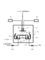
スピン処理ユニット30(処理室31)では、1枚ずつ半導体ウェーハWが供給され、その供給されたそれぞれの半導体ウェーハWに対してエッチング処理が行われる。具体的には、図2に示すように、供給された半導体ウェーハWが基板スピン機構32にセットされ、基板スピン機構32によって半導体ウェーハWが回転される。半導体ウェーハWが回転している状態で、エッチング液貯留槽20から供給される高い温度(例えば、160℃程度)に調整されたエッチング液がエッチング液噴出ノズル34から噴出する。エッチング液噴出ノズル34から噴出するエッチング液が回転する半導体ウェーハWの表面に与えられ、半導体ウェーハWに対するエッチング処理が行われる。
In the spin processing unit 30 (processing chamber 31), the semiconductor wafers W are supplied one by one and the etching processing is performed on each of the supplied semiconductor wafers W. Specifically, as shown in FIG. 2, the supplied semiconductor wafer W is set in the
そのエッチング処理では、高温のエッチング液(リン酸H3PO4、コロイダルシリカSiO2、H2Oを含む)が半導体ウェーハWに作用して、リン酸溶液の存在下で水蒸気(H2O)と窒化膜(Si3N4)とが反応し、窒化膜(Si3N4)が除去されてリン酸アンモニウム([NH4 +]3[PO4 3-])及び二水素ケイ酸(H2SiO3)が析出される。そして、前記エッチング処理に供されたエッチング液、即ち、使用済みエッチング液LETC(リン酸アンモニウム([NH4 +]3[PO4 3-])及び二水素ケイ酸(H2SiO3)を含む)が、半導体ウェーハWの回転によって飛散し、その飛散したエッチング液LETCが上昇位置に調整されたセパレータ33bによって内側液溜めカップ33cに導かれて、溜められる。
In the etching process, a high temperature etching solution (containing phosphoric acid H 3 PO 4 , colloidal silica SiO 2 , and H 2 O) acts on the semiconductor wafer W to generate water vapor (H 2 O) in the presence of a phosphoric acid solution. a nitride film (Si 3 N 4) and reacts, nitride film (Si 3 N 4) is removed ammonium phosphate ([NH 4 +] 3 [ PO 4 3-]) and dihydrogen silicate (H 2 SiO 3 ) is deposited. The etching solution used for the etching process, that is, the used etching solution LETC (ammonium phosphate ([NH 4 + ] 3 [PO 4 3- ]) and dihydrogen silicic acid (H 2 SiO 3 ) Is scattered by the rotation of the semiconductor wafer W, and the scattered etchant LETC is guided to the inner
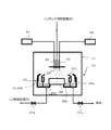
このようにして1枚の半導体ウェーハWに対するエッチング処理が終了すると、エッチング液噴出ノズル34からのエッチング液の噴出が止められ、図3に示すように、セパレータ33bが下降位置に調整された状態で、リンス液供給部41から供給されるリンス液(例えば、純水)がリンス液噴出ノズル35から噴出する。リンス液噴出ノズル35から噴出するリンス液によって回転する半導体ウェーハWの表面が洗浄される。基板スピン機構32によって高速に回転する半導体ウェーハWを洗浄して飛散するリンス液が、内側液溜めカップ33cを越えて、外側液溜めカップ33aに、内側液溜めカップ33cに既に溜められた使用済みエッチング液LETCとは分離されて回収される。
Thus, when the etching process on one semiconductor wafer W is completed, the ejection of the etching liquid from the etching
半導体ウェーハWのリンス処理が終了すると、リンス液噴出ノズル35からのリンス液の噴出が止められ、その半導体ウェーハWは、乾燥等の工程を経て処理室31から退出させられる。そして、処理室31内は、1枚の半導体ウェーハWを処理した分の使用済みエッチング液LETCが内側液溜めカップ33cに溜められた状態になる。
When the rinsing process of the semiconductor wafer W is completed, the ejection of the rinse liquid from the rinse
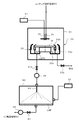
その後、図4に示すように、内側液溜めカップ33cに溜められた、1枚の半導体ウェーハを処理した分の使用済みエッチング液LETCの量に対して適量のフッ酸溶液(HF)がフッ酸供給部42から供給されてフッ酸噴出ノズル36から噴出する。前記1枚の半導体ウェーハWを処理した分の使用済みエッチング液LETCに対して供給されるフッ酸溶液(HF)の量は、予め実験等によって決定される。
フッ酸噴出ノズル36から噴出するフッ酸溶液(HF)は、高温(例えば、160℃程度)の使用済みエッチング液LETCが溜められて高温環境となる内側液溜めカップ33cに、霧状に、あるいは、その高温環境によって一部または全部が蒸気になって与えられる。内側液溜めカップ33cでは、使用済みエッチング液LETC(リン酸アンモニウム([NH4 +]3[PO4 3-])及び二水素ケイ酸(H2SiO3)を含む)とフッ酸溶液(HF)とが所定の高温環境のもとで混合して反応し、フッ化物成分が気散(気体状になって発散する)してリン酸(H3PO4)が溶液として再生される。
Thereafter, as shown in FIG. 4, an appropriate amount of hydrofluoric acid solution (HF) is hydrofluoric acid with respect to the amount of used etching solution LETC corresponding to the amount of processed one semiconductor wafer stored in the inner
The hydrofluoric acid solution (HF) jetted from the hydrofluoric
上述したようにスピン処理ユニット30(処理室31)の内側液溜めカップ33cにおいて再生されたリン酸溶液(H3PO4)が、開閉弁37aが開放された状態でポンプ38(図1参照)が動作することにより、リン酸回収槽50に供給される。前述したリン酸溶液(H3PO4)の再生処理及びそのリン酸溶液のスピン処理ユニット30(内側液溜めカップ33c)からリン酸回収槽50への転送は、1枚の半導体ウェーハWのエッチング処理が終了する毎に行われる。そして、リン酸回収槽50に順次溜められるリン酸溶液(H3PO4)は、ヒータユニット51によって所定の温度に調整されつつ、所定のタイミングでのポンプ52の動作によって、エッチング液生成槽10に戻される。
As described above, the phosphoric acid solution (H 3 PO 4 ) regenerated in the inner
上述した基板処理装置によれば、バッチ式のような大きなエッチング槽を必要とせず、スピン処理ユニット30によって1枚ずつ半導体ウェーハWのエッチング処理を行うことができる。また、スピン処理ユニット30において半導体ウェーハWのエッチング処理が終了した後に、内側液溜めカップ33cに溜められた1枚の半導体ウェーハWを処理した分の使用済みエッチング液LETCに、その使用済みエッチング液LETCの量に対して適量のフッ酸溶液が与えられるので、別途大きな設備を用いることなく、スピン処理ユニット30を利用して1枚の半導体ウェーハを処理した分の使用済みエッチング液LETCと適量のフッ酸溶液とを効率的に反応させてリン酸(H3PO4)を再生することができる。特に、もともと高温(例えば、160℃程度)に調整された使用済みエッチング液LETCは内側液溜めカップ33cにおいても高い温度状態にあるので、フッ酸溶液を霧状または蒸気状にして与えることで、使用済みエッチング液LETC及びフッ酸溶液の反応性が高くなる。そして、高温状態の使用済みエッチング液LETCが溜められた内側液溜めカップ33c内の高温環境によって反応後のフッ化物成分(例えば、H2SiF6)やアンモニア成分(NH3)が即座に気散し易くなり、更に効率的にリン酸を再生することができる。
According to the substrate processing apparatus described above, the
なお、前述した第1の実施の形態(図2〜図4参照)に係る基板処理装置では、スピン処理ユニット30の内側液溜めカップ33cに溜められた1枚の半導体ウェーハWを処理した分の使用済みエッチング液LETCに、その使用済みエッチング液LETCの量に対して適量のフッ酸溶液が与えられたが、本発明は、これに限定されない。例えば、スピン処理ユニット30において2枚以上の所定枚数の半導体ウェーハWが1枚ずつ順次エッチング処理される過程で内側液溜めカップ33cに溜められた使用済みエッチング液LETCに、その所定枚数の半導体ウェーハWのエッチング処理に要したその使用済みエッチング液LETCの量に対して適量のフッ酸溶液を与えるようにすることもできる。なお、前記所定枚数は、当該所定枚数の半導体ウェーハWをエッチング処理した分の使用済みエッチング液LETCとその使用済みエッチング液LETCの量に対する適量のフッ酸溶液LHFとを混ぜた全体の量が内側液溜めカップ33cの容量を越えない範囲で定められる。
In the substrate processing apparatus according to the first embodiment (see FIGS. 2 to 4) described above, the portion obtained by processing one semiconductor wafer W stored in the inner
このように、1枚ずつ所定枚数の半導体ウェーハWを処理した使用済みエッチング液LETCにその使用済みエッチング液LETCの量に対して適量のフッ酸溶液を混ぜる場合、前記所定枚数の半導体ウェーハWのエッチング処理が完了するまで、スピン処理ユニット30の内側液溜めカップ33cに使用済みエッチング液LETCが順次溜められていく。このため、フッ酸溶液を添加するまでに内側液溜めカップ33cの前記使用済みエッチング液LETCの温度が低下してしまうのを防止する観点から、内側液溜めカップ33cにヒータを設けることが好ましい。
As described above, in the case where the hydrofluoric acid solution is mixed with the used etching solution LETC in which the predetermined number of semiconductor wafers W are processed one by one with respect to the amount of the used etching solution LETC, the predetermined number of semiconductor wafers W The used etchant LETC is sequentially stored in the inner
上述した基板処理装置では、例えば、図5に示すようにして、スピン処理ユニット30内でリン酸溶液(H3PO4)を再生することもできる(第1の実施の形態の変形例)。 In the substrate processing apparatus described above, for example, as shown in FIG. 5, the phosphoric acid solution (H 3 PO 4 ) can also be regenerated in the spin processing unit 30 (a modification of the first embodiment).
スピン処理ユニット30において、セパレータ33bが上昇位置に調整された状態で、内側液溜めカップ33cに、1枚の半導体ウェーハWを処理した分の使用済みエッチング液の量に対して適量のフッ酸溶液LHF(HF)が予め溜められる。この状態で、スピン処理ユニット30において、基板スピン機構32によって回転される半導体ウェーハWにエッチング液貯留槽20から供給される高い温度(例えば、160℃程度)に調整されたエッチング液がエッチング液噴出ノズル34からかけられて半導体ウェーハWのエッチング処理が行われる。その過程で、回転する半導体ウェーハWの表面から飛散する使用済みエッチング液が、既にフッ酸溶液LHF(HF)が溜められた内側液溜めカップ33cに入り、内側液溜めカップ33cにおいて使用済みエッチング液LETCとフッ酸溶液LHFとが混ざり合って前述したのと同様に反応し、リン酸(H3PO4)が再生される。
In the
このように、スピン処理ユニット30の内側液溜めカップ33c内で少量の使用済みエッチング液(1枚の基板を処理する分の使用済みエッチング液)と少量のフッ酸とが反応するようにしているので、別途大きな設備を用いることなく、スピン処理ユニット30を利用して1枚の半導体ウェーハを処理した分の使用済みエッチング液と適量のフッ酸溶液LHFとを効率的に反応させてリン酸(H3PO4)を再生することができる。特に、内側液溜めカップ33cに溜められたフッ酸溶液LHFに対して高い温度の使用済みエッチング液が与えられるので、使用済みエッチング液LETC及びフッ酸溶液の反応性が高く、高温状態の使用済みエッチング液LETCの噴出により作られた高温環境によってフッ化物成分やアンモニア成分が即座に気散し易くなり、更に、効率的にリン酸を再生することができる。
Thus, a small amount of used etching solution (a used etching solution for processing a single substrate) and a small amount of hydrofluoric acid are made to react in the inner
なお、前述した変形例に係る基板処理装置(図5参照)では、スピン処理ユニット30の内側液溜めカップ33cに1枚の半導体ウェーハWを処理した分の使用済みエッチング液LETCの量に対して適量のフッ酸溶液LHFが予め溜められていたが、本発明は、これに限定されない。例えば、スピン処理ユニット30の内側液溜めカップ33cに、2枚以上の所定枚数の半導体ウェーハWを処理した分の使用済みエッチング液LETCの量に対して適量のフッ酸溶液LHFを予め溜めておき、所定枚数の半導体ウェーハWの処理が終了するまで、1枚ずつ半導体ウェーハWを処理する毎に、その使用済みエッチング液LETCを内側液溜めカップ33cに溜められた前記フッ酸溶液LHFに与えるようにすることもできる。前記所定枚数は、当該所定枚数の半導体ウェーハWを処理した使用済みエッチング液LETCの量に対して適量のフッ酸溶液LHFと当該使用済みエッチング液LETCとを混ぜた全体の量が内側液溜めカップ33cの容量を越えない範囲で定められる。
In the substrate processing apparatus (see FIG. 5) according to the modification described above, the amount of used etching solution LETC corresponding to the processing of one semiconductor wafer W in the inner
本発明の第2の実施の形態に係る基板処理装置の要部は、図6に示すように構成される。この基板処理装置では、スピン処理ユニット30内でリン酸の再生が行われるのではなく、スピン処理ユニット30の外部でリン酸の再生が行われる。
The main part of the substrate processing apparatus according to the second embodiment of the present invention is configured as shown in FIG. In this substrate processing apparatus, regeneration of phosphoric acid is not performed in the
図6において、スピン処理ユニット30の後段に再生処理槽60が設けられている。再生処理槽60には、使用済みエッチング液噴出ノズル63(使用済みエッチング供給機構)が設けられている。使用済みエッチング液噴出ノズル63には、スピン処理ユニット30の内側液溜めカップ33cから延びる経路が接続されており、その経路に開閉弁37a及びポンプ38が設けられている。また、再生処理槽60とリン酸回収槽50(図1参照)が経路によって接続され、その経路中に開閉弁61及びポンプ62が設けられている。この基板処理装置は、前述した例(図1参照)と同様に、フッ酸供給部42(フッ酸供給機構)を有しており、このフッ酸供給部42からフッ酸溶液(HF)が、スピン処理ユニット30ではなく、再生処理槽60に供給される。
In FIG. 6, a
なお、フッ酸供給部42からフッ酸溶液(HF)が再生処理槽60に供給されるので、スピン処理ユニット30には、前述した例(図1参照)のようにフッ酸噴出ノズル36が設けられてはいない。また、この基板処理装置は、図1に示す例と同様に、エッチング液を生成する機構(エッチング液生成槽10、リン酸供給部12、水供給部13、シリカ供給部14を含む)、エッチング液を溜めてスピン処理ユニット30に送る機構(エッチング液貯留槽20を含む)、再生されたリン酸溶液を溜めてエッチング液生成槽10に戻す機構(リン酸回収槽50を含む)を有している。
Since the hydrofluoric acid solution (HF) is supplied to the
上述した本発明の第2の実施の形態に係る基板処理装置では、1枚の半導体ウェーハWを処理する分のエッチング液の量に対するフッ酸溶液LHF(HF)の量は、例えば、半導体ウェーハWに形成される窒化膜(Si3N4)を処理したときに、エッチング液中に溶け込んだSi成分の濃度に対してフッ素(F)の当量が6倍程度となるような量(適量)に決められ、そのような量(適量)のフッ酸溶液LHF(HF)が予め再生処理槽60に溜められている。この状態で、スピン処理ユニット30において半導体ウェーハWのエッチング処理が終了すると、開閉弁37aが開状態に切換えられ、ポンプ38の動作により、内側液溜めカップ33cに溜まった高温状態(例えば、160℃程度)の使用済みエッチング液LETCが再生処理槽60に供給される。再生処理層60では、スピン処理ユニット30から供給される使用済みエッチング液LETCが使用済みエッチング液噴出ノズル63から噴出する。その高温状態の使用済みエッチング液は、霧状に、あるいは、その高温によって一部または全部が蒸気状になって、再生処理槽60に溜められたフッ酸溶液LHFに与えられる。再生処理槽60では、使用済みエッチング液LETCとフッ酸溶液LHFとが所定の高温環境のもとで混合して反応し、フッ化物成分やアンモニア成分が気散してリン酸(H3PO4)が再生される。
In the substrate processing apparatus according to the second embodiment of the present invention, the amount of the hydrofluoric acid solution LHF (HF) with respect to the amount of the etching solution for processing one semiconductor wafer W is, for example, the semiconductor wafer W When the nitride film (Si 3 N 4 ) formed on the substrate is processed, the equivalent amount of fluorine (F) is about 6 times the concentration of the Si component dissolved in the etching solution (appropriate amount) Such amount (appropriate amount) of hydrofluoric acid solution LHF (HF) is determined in advance and stored in the
なお、適量のフッ酸溶液(HF)は、再生処理槽60においてできるだけ広い表面積の状態で、かつ、できるだけ浅い状態で溜められることが、使用済みエッチング液LETCとフッ酸溶液LHFとが混合し易いという点で好ましい。
It should be noted that it is easy to mix the used etching solution LETC and the hydrofluoric acid solution LHF that an appropriate amount of hydrofluoric acid solution (HF) is stored in the
再生処理槽60における使用済みエッチング液LETCとフッ酸溶液LHFとの混合によってリン酸の再生がなされたと見込まれるタイミングで開閉弁61が開放され、再生処理槽60において再生されたリン酸溶液(H3PO4)は、ポンプ62の動作により、リン酸回収槽50(図1参照)に供給される。そして、前述したのと同様に、リン酸回収槽50からエッチング液生成槽10に戻される。開閉弁61の開放タイミングは、予め実験等で決定される。
The on-off
このような基板処理装置によれば、第1の実施の形態(図1乃至図4参照)と同様に、バッチ式のような大きなエッチング槽を必要とせず、スピン処理ユニット30によって1枚ずつ半導体ウェーハWのエッチング処理を行うことができる。また、予めフッ酸溶液LHFが溜められた再生処理槽60にスピン処理ユニット30の内側液溜めカップ33cに溜められた1枚の半導体ウェーハWを処理した分の量の使用済みエッチング液LETCが供給され、再生処理槽60において、使用済みエッチング液LETCとフッ酸溶液LHFとが反応してリン酸が再生されるので、1枚分の半導体ウェーハWを処理した分の使用済みエッチング液LETCとそれに対して適量のフッ酸溶液LHFを溜めることのできる程度の大きさの再生処理槽60を用いて、使用済みエッチング液LETCとフッ酸溶液LHFとを効率的に反応させて、リン酸を再生することができる。特に、再生処理槽60に溜められたフッ酸溶液LHFに高い温度の使用済みエッチング液LETCを霧状または蒸気状にして与えているので、使用済みエッチング液LETC及びフッ酸溶液LHFの反応性が高く、高温状態の使用済みエッチング液LETCの噴出により作り出される高温環境によってフッ化物成分やアンモニア成分が即座に気散し易くなり、更に、効率的にリン酸を再生することができる。
According to such a substrate processing apparatus, as in the first embodiment (see FIGS. 1 to 4), the
なお、前述した第2の実施の形態(図6参照)に係る基板処理装置では、スピン処理ユニット30の内側液溜めカップ33cに溜められた1枚の半導体ウェーハWを処理した分の使用済みエッチング液LETCを、再生処理槽60に溜められた前記使用済みエッチング液LETCに対して適量のフッ酸溶液LHFに、霧状または蒸気状にして与えているが、本発明は、これに限定されない。例えば、2枚以上の所定枚数の半導体ウェーハWをエッチング処理した分の使用済みエッチング液LETCの量に対して適量のフッ酸溶液を予め再生処理槽60に溜めておき、スピン処理ユニット30において前記所定枚数の半導体ウェーハWが1枚ずつ順次エッチング処理される過程で内側液溜めカップ33cに溜められた使用済みエッチング液LETCを霧状または蒸気状にして再生処理槽60に溜められた前記フッ酸溶液に与えるようにすることもできる。前記所定枚数は、当該所定枚数の半導体ウェーハWのエッチング処理した分の使用済みエッチング液LETCの量が内側液溜めカップ33cの容量を越えない範囲で定められる。
In the substrate processing apparatus according to the second embodiment (see FIG. 6) described above, the used etching of the processed semiconductor wafer W stored in the inner
この場合も、内側液溜めカップ33cに予め溜められた使用済みエッチング液LETCの温度低下を防止する観点から、内側液溜めカップ33cにヒータを設けることが好ましい。
Also in this case, it is preferable to provide a heater in the inner
また、前述した第2の実施の形態に係る基板処理装置では、再生処理槽60内に予めフッ酸溶液LHF(HF)を溜めておき、スピン処理ユニット30の内側液溜めカップ33cに溜められた使用済みエッチング液LETCを霧状または蒸気状にして再生処理槽60内に噴出するようにしたが、本発明は、これに限られない。例えば、スピン処理ユニット30の内側液溜めカップ33cに溜められた使用済みエッチング液LETCを予め再生処理槽60に供給して溜めておき、この状態で、フッ酸溶液LHFを霧状または蒸気状にして再生処理槽60内に噴出するようにしてもよい。この場合も、1枚の半導体ウェーハを処理した分の使用済みエッチング液LETCは、再生処理槽60においてできるだけ広い表面積の状態で、かつ、できるだけ浅い状態で溜められることが、使用済みエッチング液LETCとフッ酸溶液LHFとが混合し易いという点で好ましい。
Further, in the substrate processing apparatus according to the second embodiment described above, the hydrofluoric acid solution LHF (HF) is stored in advance in the
本発明の第3の実施の形態に係る基板処理装置の要部は、図7に示すように構成される。この基板処理装置も、スピン処理ユニット30内でリン酸の再生が行われるのではなく、スピン処理ユニット30の外部に設けられた再生処理槽60においてリン酸の再生が行われる。図7に示す要部を備えた基板処理装置は、再生処理槽60にフッ酸噴出ノズル64(フッ酸供給機構)が設けられている点で、第2の実施の形態に係る基板処理装置(図6参照)で異なっている。
The main part of the substrate processing apparatus according to the third embodiment of the present invention is configured as shown in FIG. Also in this substrate processing apparatus, regeneration of phosphoric acid is not performed in the
このような基板処理装置では、スピン処理ユニット30において半導体ウェーハWのエッチング処理が終了すると、開閉弁37aが開状態に切換えられ、ポンプ38の動作により、内側液溜めカップ33cに溜まった使用済みエッチング液LETCが再生処理槽60に供給される。また、同時に、フッ酸供給部42からフッ酸溶液(HF)が再生処理槽60に供給される。再生処理槽60では、スピン処理ユニット30から供給される高温状態(例えば、160℃程度)の使用済みエッチング液LETCが使用済みエッチング液噴出ノズル63から霧状に、あるいは、その高温によって一部または全部が蒸気状になって噴出し、同時に、フッ酸供給部42から供給されるフッ酸溶液(HF)がフッ酸ノズル64から、液状にて、好ましくは霧状になって、噴出する。そして、高温状態の霧状または蒸気状の使用済みエッチング液LETCと、その高温状態の使用済みエッチング液LETCが噴出することにより作られる高温環境によって全部または一部が蒸気化するフッ酸溶液とがその高温環境のもとで混ざり合って反応し、フッ化物成分やアンモニア成分が気散してリン酸(H3PO4)が再生される。
In such a substrate processing apparatus, when the etching processing of the semiconductor wafer W is completed in the
なお、霧状となる用済みエッチング液LETC及びフッ酸溶液(HF)のそれぞれの粒径は、できるだけ小さいことが、混合し易く、高い反応性を呈し得るという点で好ましい。 In addition, it is preferable that the particle diameter of the spent etching solution LETC and the hydrofluoric acid solution (HF) in the form of a mist be as small as possible because they can be easily mixed and can exhibit high reactivity.
このような基板処理装置によれば、第1の実施の形態(図1乃至図4参照)及び第2の実施の形態(図6参照)と同様に、バッチ式のような大きなエッチング槽を必要とせず、スピン処理ユニット30によって1枚ずつ半導体ウェーハWのエッチング処理を行うことができる。また、再生処理槽60において、スピン処理ユニット30の内側液溜めカップ33cに溜められた1枚の半導体ウェーハWを処理した分の量の使用済みエッチング液LETCとそのエッチング液の量に対して適量のフッ酸溶液LHFとが霧状または蒸気状になって反応してリン酸が再生されるので、第2の実施の形態と同様に、比較的小さい再生処理槽60を用いて、使用済みエッチング液LETCとフッ酸溶液LHFとを効率的に反応させて、リン酸を再生することができる。特に、再生処理槽60に霧状または蒸気状の使用済みエッチング液LETCとフッ酸溶液LHFとが所定の高温環境で混合されているので、反応性が高く、高温環境によってフッ化物成分やアンモニア成分が即座に気散し易くなり、更に、効率的に反応させてリン酸を再生することができる。
According to such a substrate processing apparatus, as in the first embodiment (see FIGS. 1 to 4) and the second embodiment (see FIG. 6), a large etching bath such as a batch type is required. Instead, the
なお、前述した第3の実施の形態(図7参照)に係る基板処理装置では、スピン処理ユニット30の内側液溜めカップ33cに溜められた1枚の半導体ウェーハWを処理した分の使用済みエッチング液LETCと、その使用済みエッチング液LETCの量に対して適量のフッ酸溶液LHFとが、再生処理槽60内で、霧状または蒸気状にて混ざり合って反応するものであったが、本発明はこれに限定されない。例えば、スピン処理ユニット30において2枚以上の所定枚数の半導体ウェーハWが1枚ずつ順次エッチング処理される過程で内側液溜めカップ33cに溜められた使用済みエッチング液LETCと、その使用済みエッチング液LETCの量に対して適量のフッ酸溶液LHFとが、再生処理槽60内で、霧状または蒸気状にて混ざり合って反応するものであってもよい。前記所定枚数は、当該所定枚数の半導体ウェーハWのエッチング処理した分の使用済みエッチング液LETCの量が内側液溜めカップ33cの容量を越えない範囲で定められる。
In the substrate processing apparatus according to the third embodiment (see FIG. 7) described above, the used etching for processing one semiconductor wafer W stored in the inner
この場合も、内側液溜めカップ33cに予め溜められた使用済みエッチング液LETCの温度低下を防止する観点から、内側液溜めカップ33cにヒータを設けることが好ましい。
Also in this case, it is preferable to provide a heater in the inner
本発明の第4の実施の形態に係る基板処理装置の要部は、図8に示すように構成される。この基板処理装置は、前述した各基板処理装置のように、半導体ウェーハWを1枚ずつ処理する枚葉式のものではなく、複数の半導体ウェーハWを一括して処理するバッチ式のものである。 The main part of the substrate processing apparatus according to the fourth embodiment of the present invention is configured as shown in FIG. This substrate processing apparatus is not a single-wafer type that processes semiconductor wafers W one by one like the above-described substrate processing apparatuses, but is a batch type that collectively processes a plurality of semiconductor wafers W. .
図8において、この基板処理装置は、バッチ処理槽70(エッチング処理部)と、再生処理槽80とを有している。バッチ処理槽70は、リン酸溶液(H3PO4)、純水(H2O)及びコロイダルシリカ(SiO2)を混合してエッチング液を生成するエッチング液生成槽(図1におけるエッチング液生成槽10に相当)に接続されている。そして、バッチ処理槽70には、所定の枚数の半導体ウェーハWをエッチング処理するに十分なエッチング液がエッチング生成槽から供給されて溜められる。バッチ処理槽70にはヒータユニット71が設けられ、溜められたエッチング液が所定の温度に維持される。
In FIG. 8, the substrate processing apparatus includes a batch processing tank 70 (etching processing unit) and a
基板処理装置は、更に、フッ酸供給部84を有している。再生処理槽80には、使用済みエッチング液噴出ノズル81及びフッ酸噴出ノズル82が設けられている。使用済みエッチング液噴出ノズル81はバッチ処理槽70と開閉弁72を介して接続され、フッ酸噴出ノズル82はフッ酸供給部84に接続されている。また、再生処理槽80の底部から延びる2つの経路のうち一方は、開閉弁86aを介してリン酸回収槽(図1に示すリン酸回収槽50に相当)に接続され、他方は、開閉弁86bを介して廃液槽に接続されている。
The substrate processing apparatus further includes a hydrofluoric
このような基板処理装置では、バッチ処理槽70において、所定枚数の半導体ウェーハWに対するエッチング処理が一括的に行われる。所定の枚数を単位として行われる半導体ウェーハWに対するエッチング処理が繰り返し行われる過程で、例えば、各半導体ウェーハWのエッチングレートが所定範囲に維持されるように、エッチング液生成槽から新たに生成されるエッチング液が所定のタイミングでバッチ処理槽70に供給される。また、開閉弁72が所定のタイミングで所定時間開放されることによりバッチ処理槽70から使用済みエッチング液LETCが再生処理槽80に供給される。
In such a substrate processing apparatus, etching processing is collectively performed on a predetermined number of semiconductor wafers W in the
再生処理槽80では、バッチ処理槽70から所定のタイミングで所定時間供給される高温状態(例えば、160℃程度)の使用済みエッチング液LETCが使用済みエッチング液噴出ノズル81から霧状に、あるいは、その高温によって一部または全部が蒸気状になって噴出し、それに同期して、フッ酸供給部84から供給されるフッ酸溶液LHFがフッ酸噴出ノズル82から、液状にて、好ましくは霧状になって噴出する。そして、それら霧状または蒸気状の使用済みエッチング液LETCと、その高温状態の使用済みエッチング液LETCが噴出することにより作られる高温環境によって全部または一部が蒸気化するフッ酸溶液LHFとがその高温環境のもとで混ざり合って反応し、フッ化物成分やアンモニア成分が気散してリン酸(H3PO4)が再生される。
In the
再生処理槽80において再生されたリン酸溶液は、リン酸回収槽に供給され、リン酸回収槽から更にエッチング液生成槽に戻される。
The phosphoric acid solution regenerated in the
上述した基板処理装置によれば、バッチ処理槽70において所定枚数の半導体ウェーハWの一括的なエッチング処理に多くの量のエッチング液を用いたとしても、再生処理槽80において使用済みエッチング液LETCとフッ酸溶液LHFとが霧状または蒸気状にて混合し、反応し合うので、複数の半導体ウェーハWに対するエッチング処理後の全ての量の使用済みエッチング液LETCとフッ酸溶液LHFとを溜めて反応させる設備を用いることなく、使用済みエッチング液とフッ酸溶液とを効率的に反応させてリン酸を再生することができる。
According to the substrate processing apparatus described above, even if a large amount of etching solution is used for batch etching processing of a predetermined number of semiconductor wafers W in the
なお、第2の実施の形態(図6参照)、第3の実施の形態(図7参照)及び第4の実施の形態(図8参照)では、使用済みエッチング液噴出ノズル63、81から使用済みエッチング液LETCが霧状または蒸気状になって噴出するものであったが、使用済みエッチング液LETCは、霧状や蒸気状になることなく、液状のまま噴出するものであってもよい。
In the second embodiment (see FIG. 6), the third embodiment (see FIG. 7) and the fourth embodiment (see FIG. 8), the used
10 エッチング液生成槽
11 ヒータユニット
12 リン酸供給部
13 水供給部
14 シリカ供給部
15 ポンプ
16 切替え弁
17 濃度検出器
20 エッチング液貯留槽
21 ヒータユニット
22a、22b 開閉弁
23 ポンプ
24 流量計
25 切替え弁
26 冷却器
30 スピン処理ユニット
31 処理室
32 基板スピン機構
33 セパレートカップ機構
34 エッチング液噴出ノズル
35 リンス液噴出ノズル
36 フッ酸噴出ノズル
37a、37b 開閉弁
38 ポンプ
41 リンス液供給部
42 フッ酸供給部
50 リン酸回収槽
51 ヒータユニット
52 ポンプ
60 再生処理槽
61 開閉弁
62 ポンプ
63 使用済みエッチング液噴出ノズル
64 フッ酸噴出ノズル
70 バッチ処理槽
71 ヒータユニット
80 再生処理槽
81 使用済みエッチング液噴出ノズル
82 フッ酸噴出ノズル
84 フッ酸供給部
86a、86b 開閉弁
DESCRIPTION OF
Claims (8)
1枚ずつ供給される前記基板のそれぞれを前記基板スピン機構で回転させ、前記回転する前記基板に前記エッチング液供給機構から前記エッチング液を供給して前記基板に対するエッチング処理を行い、窒化膜を除去するエッチング処理ステップと、
前記エッチング処理ステップにて1枚ずつ所定枚数の前記基板を処理した分の使用済みエッチング液と、フッ酸溶液とを、前記液溜め部にて混合してリン酸を再生するリン酸再生ステップと、
前記リン酸再生ステップにより得られたリン酸を前記エッチング処理ステップにて使用されるべきエッチング液に戻すリン酸回収ステップとを有し、
前記リン酸再生ステップは、前記使用済みエッチング液と前記フッ酸溶液とを、それらのうちの少なくともいずれか一方を霧状または蒸気状にして混合する基板処理方法。 A substrate spin mechanism for rotating a substrate, an etchant supply mechanism for supplying an etchant to the surface of the substrate rotated by the substrate spin mechanism, and the etchant supplied to the surface of the rotating substrate are for the substrate. A substrate processing method for processing a silicon substrate on which a nitride film is formed with an etching solution containing phosphoric acid using an etching processing unit having a liquid storage unit for storing used etching solution after scattering from the surface. There,
Each of the substrates supplied one by one is rotated by the substrate spin mechanism, and the etching solution is supplied to the rotating substrate from the etchant supply mechanism to etch the substrate, thereby removing the nitride film. Etching process steps,
A phosphoric acid regenerating step of regenerating phosphoric acid by mixing a used etching solution for treating a predetermined number of the substrates one by one in the etching step and a hydrofluoric acid solution in the liquid reservoir ; ,
And a phosphoric acid recovery step of returning the phosphoric acid obtained by the phosphoric acid regeneration step to the etching solution to be used in the etching step.
The said phosphoric acid reproduction | regeneration step mixes the said used etching liquid and the said hydrofluoric acid solution, making at least any one of them misty or vaporous, and mixing them.
1枚ずつ供給される基板のそれぞれを回転させる基板スピン機構と、前記基板スピン機構によって回転される前記基板の表面に前記エッチング液を供給するエッチング液供給機構と、前記回転する基板の表面に供給される前記エッチング液が前記基板の表面から飛散した後の使用済みエッチング液を溜める液溜め部とを有し、前記基板に前記エッチング液を供給して前記基板に対するエッチング処理を行い、窒化膜を除去するエッチング処理部と、
前記液溜め部にフッ酸溶液を供給するフッ酸供給機構を有し、前記使用済みエッチング液と、前記フッ酸溶液とを、前記液溜め部にて混合してリン酸を再生するリン酸再生部と、
前記リン酸再生部により得られたリン酸を前記エッチング処理部にて使用されるべきエッチング液に戻すリン酸回収部と、
を有し、
前記リン酸再生部は、前記使用済みエッチング液と前記フッ酸溶液とを、それらのうちの少なくともいずれか一方を霧状または蒸気状にして混合する基板処理装置。 A substrate processing apparatus for processing a silicon substrate on which a nitride film is formed with an etching solution containing phosphoric acid,
A substrate spin mechanism for rotating each of the substrates supplied one by one, an etching liquid supply mechanism for supplying the etching solution to the surface of the substrate rotated by the substrate spin mechanism, and a supply to the surface of the rotating substrate And the liquid storage portion for storing used etching liquid after the etching liquid is scattered from the surface of the substrate, the etching liquid is supplied to the substrate to perform etching processing on the substrate, and a nitride film is formed. An etched portion to be removed,
A hydrofluoric acid supply mechanism for supplying hydrofluoric acid solution to the liquid reservoir, wherein the spent etching solution, and the hydrofluoric acid solution and mixed to phosphoric acid regeneration to regenerate phosphoric acid in the liquid reservoir Department,
A phosphoric acid recovery unit for returning the phosphoric acid obtained by the phosphoric acid regeneration unit to an etching solution to be used in the etching processing unit ;
Have
The said phosphoric acid reproduction | regeneration part is a substrate processing apparatus which makes the said used etching liquid and the said hydrofluoric acid solution misty or vapor-like and mixes at least any one of them.
Priority Applications (7)
| Application Number | Priority Date | Filing Date | Title |
|---|---|---|---|
| JP2014170205A JP6502633B2 (en) | 2013-09-30 | 2014-08-25 | Substrate processing method and substrate processing apparatus |
| TW103130267A TWI539516B (en) | 2013-09-30 | 2014-09-02 | Substrate processing method and substrate processing device |
| US14/490,939 US10319602B2 (en) | 2013-09-30 | 2014-09-19 | Substrate treatment method and substrate treatment apparatus |
| CN201410504744.7A CN104517827B (en) | 2013-09-30 | 2014-09-26 | Substrate processing method and substrate processing apparatus |
| CN201710432802.3A CN107256842B (en) | 2013-09-30 | 2014-09-26 | Substrate processing method and substrate processing apparatus |
| KR20140130302A KR20150037632A (en) | 2013-09-30 | 2014-09-29 | Substrate treatment method and substrate treatment device |
| KR1020170027025A KR102129450B1 (en) | 2013-09-30 | 2017-03-02 | Substrate treatment method and substrate treatment device |
Applications Claiming Priority (5)
| Application Number | Priority Date | Filing Date | Title |
|---|---|---|---|
| JP2013205624 | 2013-09-30 | ||
| JP2013205624 | 2013-09-30 | ||
| JP2013259658 | 2013-12-16 | ||
| JP2013259658 | 2013-12-16 | ||
| JP2014170205A JP6502633B2 (en) | 2013-09-30 | 2014-08-25 | Substrate processing method and substrate processing apparatus |
Related Child Applications (1)
| Application Number | Title | Priority Date | Filing Date |
|---|---|---|---|
| JP2017158528A Division JP6352511B2 (en) | 2013-09-30 | 2017-08-21 | Substrate processing equipment |
Publications (3)
| Publication Number | Publication Date |
|---|---|
| JP2015135943A JP2015135943A (en) | 2015-07-27 |
| JP2015135943A5 JP2015135943A5 (en) | 2017-10-05 |
| JP6502633B2 true JP6502633B2 (en) | 2019-04-17 |
Family
ID=52740578
Family Applications (1)
| Application Number | Title | Priority Date | Filing Date |
|---|---|---|---|
| JP2014170205A Active JP6502633B2 (en) | 2013-09-30 | 2014-08-25 | Substrate processing method and substrate processing apparatus |
Country Status (5)
| Country | Link |
|---|---|
| US (1) | US10319602B2 (en) |
| JP (1) | JP6502633B2 (en) |
| KR (2) | KR20150037632A (en) |
| CN (2) | CN104517827B (en) |
| TW (1) | TWI539516B (en) |
Families Citing this family (48)
| Publication number | Priority date | Publication date | Assignee | Title |
|---|---|---|---|---|
| KR102057220B1 (en) * | 2013-02-19 | 2020-01-22 | 삼성전자주식회사 | Chemical supplier, processing apparatus including the chemical supplier and method of processing a substrate using the cleaning apparatus |
| JP6502633B2 (en) * | 2013-09-30 | 2019-04-17 | 芝浦メカトロニクス株式会社 | Substrate processing method and substrate processing apparatus |
| DE102013220810A1 (en) * | 2013-10-15 | 2015-04-16 | Robert Bosch Gmbh | Device for the homogeneous wet-chemical treatment of substrates |
| JP6320869B2 (en) * | 2014-07-29 | 2018-05-09 | 株式会社Screenホールディングス | Substrate processing apparatus and substrate processing method |
| KR101671118B1 (en) | 2014-07-29 | 2016-10-31 | 가부시키가이샤 스크린 홀딩스 | Substrate processing apparatus and substrate processing method |
| JP6359925B2 (en) * | 2014-09-18 | 2018-07-18 | 株式会社Screenホールディングス | Substrate processing equipment |
| JP6383254B2 (en) * | 2014-11-04 | 2018-08-29 | 株式会社東芝 | Processing apparatus and processing method |
| US10283384B2 (en) | 2015-04-27 | 2019-05-07 | Taiwan Semiconductor Manufacturing Co., Ltd. | Method for etching etch layer and wafer etching apparatus |
| KR101757812B1 (en) | 2015-05-29 | 2017-07-14 | 세메스 주식회사 | System for regenerating the phosphoric acid solution, and Apparatus and method for treating substrate |
| CN105065914A (en) * | 2015-07-21 | 2015-11-18 | 武汉新芯集成电路制造有限公司 | Etchant delivering pipeline system and method used in wet etching process |
| TWI619142B (en) * | 2015-09-30 | 2018-03-21 | 芝浦機械電子裝置股份有限公司 | Substrate processing apparatus and substrate processing method |
| KR102498830B1 (en) * | 2015-12-29 | 2023-02-10 | 솔브레인 주식회사 | Method of refining etching composition |
| JP6861039B2 (en) * | 2016-03-30 | 2021-04-21 | 芝浦メカトロニクス株式会社 | Substrate processing equipment and substrate processing method |
| US10325779B2 (en) * | 2016-03-30 | 2019-06-18 | Tokyo Electron Limited | Colloidal silica growth inhibitor and associated method and system |
| TWI738757B (en) * | 2016-04-05 | 2021-09-11 | 美商維克儀器公司 | An apparatus and method to control etch rate through adaptive spiking of chemistry |
| KR101870650B1 (en) * | 2016-08-25 | 2018-06-27 | 세메스 주식회사 | Substrate treating apparatus and substrate treating method |
| CN106783692B (en) * | 2017-01-12 | 2018-01-12 | 广东工业大学 | A kind of processing unit (plant) of micro-structural etching |
| JP6909620B2 (en) * | 2017-04-20 | 2021-07-28 | 株式会社Screenホールディングス | Substrate processing method |
| JP6777704B2 (en) * | 2017-10-20 | 2020-10-28 | 東京エレクトロン株式会社 | Substrate processing equipment, substrate processing method and storage medium |
| KR102264002B1 (en) * | 2017-10-20 | 2021-06-11 | 도쿄엘렉트론가부시키가이샤 | Substrate processing apparatus, substrate processing method and recording medium |
| JP7004144B2 (en) * | 2017-10-25 | 2022-01-21 | 株式会社Screenホールディングス | Board processing equipment and board processing method |
| JP6917868B2 (en) * | 2017-11-15 | 2021-08-11 | 株式会社Screenホールディングス | Board processing method and board processing equipment |
| KR102495512B1 (en) * | 2017-12-26 | 2023-02-06 | 솔브레인 주식회사 | Composition for etching and manufacturing method of semiconductor device using the same |
| JP6976166B2 (en) * | 2017-12-28 | 2021-12-08 | 東京エレクトロン株式会社 | Board processing method and board processing equipment |
| CN108109946A (en) * | 2018-01-16 | 2018-06-01 | 昆山成功环保科技有限公司 | A kind of etching apparatus |
| JP7045199B2 (en) | 2018-01-23 | 2022-03-31 | 株式会社Screenホールディングス | Board processing equipment and board processing method |
| KR20190099814A (en) * | 2018-02-20 | 2019-08-28 | 삼성전자주식회사 | Liquid chemical recycle system, liquid chemical supply system, and method for manufacturing a semiconductor device using the same |
| JP2020035794A (en) * | 2018-08-27 | 2020-03-05 | キオクシア株式会社 | Substrate processing apparatus and method of manufacturing semiconductor device |
| CN109037119B (en) * | 2018-09-13 | 2021-04-09 | 友达光电(昆山)有限公司 | Etching device |
| JP7096112B2 (en) | 2018-09-13 | 2022-07-05 | キオクシア株式会社 | Semiconductor manufacturing equipment and methods for manufacturing semiconductor equipment |
| JP7158249B2 (en) * | 2018-11-09 | 2022-10-21 | 東京エレクトロン株式会社 | SUBSTRATE PROCESSING METHOD, SUBSTRATE PROCESSING APPARATUS, AND STORAGE MEDIUM |
| JP7126927B2 (en) * | 2018-11-16 | 2022-08-29 | 株式会社Screenホールディングス | SUBSTRATE PROCESSING APPARATUS AND SUBSTRATE PROCESSING METHOD |
| JP7203579B2 (en) * | 2018-11-26 | 2023-01-13 | 株式会社Screenホールディングス | Substrate processing equipment |
| JP7190892B2 (en) * | 2018-12-12 | 2022-12-16 | 東京エレクトロン株式会社 | SUBSTRATE PROCESSING APPARATUS AND PROCESSING LIQUID CONCENTRATION METHOD |
| CN109698148B (en) * | 2018-12-27 | 2021-04-13 | 上海华力集成电路制造有限公司 | A kind of pipeline equipment for temperature control of phosphoric acid machine |
| JP2020141006A (en) * | 2019-02-27 | 2020-09-03 | キオクシア株式会社 | Manufacturing method for substrate processing equipment and semiconductor equipment |
| CN118299300A (en) * | 2019-03-15 | 2024-07-05 | 东京毅力科创株式会社 | Substrate processing device and substrate processing method |
| KR102346529B1 (en) * | 2019-06-24 | 2021-12-31 | 세메스 주식회사 | Unit for supplying liquid, Apparatus and Method for treating substrate with the unit |
| JP7391297B2 (en) * | 2019-06-28 | 2023-12-05 | 株式会社Flosfia | Etching processing method and etching processing equipment |
| CN111106041A (en) * | 2019-12-10 | 2020-05-05 | 上海华力集成电路制造有限公司 | Wet etching machine table and recovery method of wet etching liquid medicine |
| CN111354637B (en) * | 2020-02-28 | 2023-07-25 | 通威太阳能(眉山)有限公司 | Method for washing graphite boat by recycling hydrofluoric acid |
| JP7413113B2 (en) * | 2020-03-24 | 2024-01-15 | 株式会社Screenホールディングス | Processing liquid temperature control method, substrate processing method, processing liquid temperature control device, and substrate processing system |
| JP7486372B2 (en) * | 2020-07-29 | 2024-05-17 | 東京エレクトロン株式会社 | Substrate processing apparatus and substrate processing method |
| JP7467279B2 (en) * | 2020-08-18 | 2024-04-15 | キオクシア株式会社 | Chemical application device and viscosity adjustment bottle |
| KR102715366B1 (en) * | 2020-12-18 | 2024-10-10 | 세메스 주식회사 | Apparatus and method for supplying treating liquid |
| KR102869665B1 (en) * | 2021-07-08 | 2025-10-16 | 주식회사 제우스 | Etching apparatus and control method thereof |
| JP7438172B2 (en) * | 2021-09-13 | 2024-02-26 | 芝浦メカトロニクス株式会社 | Feeding device, feeding system |
| CN113943579A (en) * | 2021-10-15 | 2022-01-18 | 中国科学院上海微系统与信息技术研究所 | Combined etching liquid, etching system and etching method |
Family Cites Families (15)
| Publication number | Priority date | Publication date | Assignee | Title |
|---|---|---|---|---|
| JPH04288831A (en) * | 1991-03-18 | 1992-10-13 | Nec Yamagata Ltd | Semiconductor manufacturing apparatus |
| US6086711A (en) * | 1997-10-06 | 2000-07-11 | Nisene Technology Group | Vapor generation system and process |
| US6399517B2 (en) * | 1999-03-30 | 2002-06-04 | Tokyo Electron Limited | Etching method and etching apparatus |
| JP2003215002A (en) * | 2002-01-17 | 2003-07-30 | Dainippon Screen Mfg Co Ltd | Substrate processing apparatus and substrate processing method |
| JP2005064199A (en) * | 2003-08-11 | 2005-03-10 | Seiko Epson Corp | Chemical solution regeneration processing apparatus, semiconductor manufacturing apparatus, chemical solution regeneration processing method, and semiconductor device manufacturing method |
| JP2005079212A (en) * | 2003-08-29 | 2005-03-24 | Trecenti Technologies Inc | Semiconductor manufacturing apparatus and semiconductor device manufacturing method |
| TWI334624B (en) * | 2006-01-30 | 2010-12-11 | Dainippon Screen Mfg | Apparatus for and method for processing substrate |
| JP2008066351A (en) * | 2006-09-05 | 2008-03-21 | Dainippon Screen Mfg Co Ltd | Substrate processing equipment |
| JP4944558B2 (en) * | 2006-10-12 | 2012-06-06 | アプリシアテクノロジー株式会社 | Etching solution regeneration method, etching method and etching apparatus |
| JP4412502B2 (en) * | 2007-02-14 | 2010-02-10 | セイコーエプソン株式会社 | Processing apparatus and method for manufacturing semiconductor device |
| JP4424517B2 (en) * | 2007-02-19 | 2010-03-03 | セイコーエプソン株式会社 | PROCESSING DEVICE AND SEMICONDUCTOR DEVICE MANUFACTURING METHOD |
| JP4358259B2 (en) * | 2007-06-05 | 2009-11-04 | 株式会社東芝 | Semiconductor manufacturing apparatus and semiconductor manufacturing method |
| KR101592058B1 (en) * | 2010-06-03 | 2016-02-05 | 도쿄엘렉트론가부시키가이샤 | Liquid processing apparatus for substrate |
| JP2012074601A (en) * | 2010-09-29 | 2012-04-12 | Dainippon Screen Mfg Co Ltd | Substrate processing apparatus and substrate processing method |
| JP6502633B2 (en) * | 2013-09-30 | 2019-04-17 | 芝浦メカトロニクス株式会社 | Substrate processing method and substrate processing apparatus |
-
2014
- 2014-08-25 JP JP2014170205A patent/JP6502633B2/en active Active
- 2014-09-02 TW TW103130267A patent/TWI539516B/en active
- 2014-09-19 US US14/490,939 patent/US10319602B2/en active Active
- 2014-09-26 CN CN201410504744.7A patent/CN104517827B/en active Active
- 2014-09-26 CN CN201710432802.3A patent/CN107256842B/en active Active
- 2014-09-29 KR KR20140130302A patent/KR20150037632A/en not_active Ceased
-
2017
- 2017-03-02 KR KR1020170027025A patent/KR102129450B1/en active Active
Also Published As
| Publication number | Publication date |
|---|---|
| US20150093906A1 (en) | 2015-04-02 |
| JP2015135943A (en) | 2015-07-27 |
| CN104517827A (en) | 2015-04-15 |
| TW201530646A (en) | 2015-08-01 |
| TWI539516B (en) | 2016-06-21 |
| CN104517827B (en) | 2017-06-27 |
| US10319602B2 (en) | 2019-06-11 |
| CN107256842A (en) | 2017-10-17 |
| KR20170029453A (en) | 2017-03-15 |
| KR102129450B1 (en) | 2020-07-03 |
| KR20150037632A (en) | 2015-04-08 |
| CN107256842B (en) | 2021-06-04 |
Similar Documents
| Publication | Publication Date | Title |
|---|---|---|
| JP6502633B2 (en) | Substrate processing method and substrate processing apparatus | |
| JP6352511B2 (en) | Substrate processing equipment | |
| JP2015135943A5 (en) | ||
| KR102541745B1 (en) | Wet etching method, substrate liquid processing device and storage medium | |
| JP5715981B2 (en) | Substrate processing method and substrate processing apparatus | |
| JP6066899B2 (en) | Wet processing of microelectronic substrates by controlling fluid mixing near the substrate surface | |
| JP2005183937A (en) | Semiconductor device manufacturing method and resist removal cleaning apparatus | |
| CN103153490A (en) | Method and apparatus for drying semiconductor wafer | |
| KR20130121033A (en) | Substrate processing apparatus and substrate processing method | |
| US20170062231A1 (en) | Substrate treatment apparatus, substrate treatment method, and etchant | |
| US20190083918A1 (en) | Manufacturing apparatus and exhaust gas treatment apparatus | |
| KR20180054598A (en) | Substrate processing method, substrate processing apparatus, and storage medium | |
| TW201248705A (en) | Substrate processing system and substrate processing method using the same | |
| US20210118704A1 (en) | Substrate processing apparatus and apparatus cleaning method | |
| US20190385869A1 (en) | Substrate processing apparatus and processing liquid reuse method | |
| KR20190032033A (en) | Method and apparatus for in-situ dry clean processing | |
| US20170338102A1 (en) | Substrate treatment apparatus and substrate treatment method | |
| TW202449869A (en) | Substrate processing method | |
| US11745213B2 (en) | Substrate processing apparatus and apparatus cleaning method | |
| KR20200144200A (en) | Substrate treatment apparatus | |
| CN115136282B (en) | Substrate processing device and substrate processing method | |
| JP5961535B2 (en) | Substrate liquid processing method, substrate liquid processing system, and storage medium | |
| JP2007273806A (en) | Semiconductor substrate cleaning method and cleaning apparatus | |
| JP7065622B2 (en) | Board processing equipment and board processing method | |
| JP4227694B2 (en) | Wafer surface treatment equipment |
Legal Events
| Date | Code | Title | Description |
|---|---|---|---|
| A521 | Request for written amendment filed |
Free format text: JAPANESE INTERMEDIATE CODE: A523 Effective date: 20170821 |
|
| A621 | Written request for application examination |
Free format text: JAPANESE INTERMEDIATE CODE: A621 Effective date: 20170821 |
|
| A977 | Report on retrieval |
Free format text: JAPANESE INTERMEDIATE CODE: A971007 Effective date: 20180525 |
|
| A131 | Notification of reasons for refusal |
Free format text: JAPANESE INTERMEDIATE CODE: A131 Effective date: 20180605 |
|
| A601 | Written request for extension of time |
Free format text: JAPANESE INTERMEDIATE CODE: A601 Effective date: 20180803 |
|
| A521 | Request for written amendment filed |
Free format text: JAPANESE INTERMEDIATE CODE: A523 Effective date: 20181004 |
|
| TRDD | Decision of grant or rejection written | ||
| A01 | Written decision to grant a patent or to grant a registration (utility model) |
Free format text: JAPANESE INTERMEDIATE CODE: A01 Effective date: 20190319 |
|
| A61 | First payment of annual fees (during grant procedure) |
Free format text: JAPANESE INTERMEDIATE CODE: A61 Effective date: 20190322 |
|
| R150 | Certificate of patent or registration of utility model |
Ref document number: 6502633 Country of ref document: JP Free format text: JAPANESE INTERMEDIATE CODE: R150 |