JP7190892B2 - SUBSTRATE PROCESSING APPARATUS AND PROCESSING LIQUID CONCENTRATION METHOD - Google Patents
SUBSTRATE PROCESSING APPARATUS AND PROCESSING LIQUID CONCENTRATION METHOD Download PDFInfo
- Publication number
- JP7190892B2 JP7190892B2 JP2018232113A JP2018232113A JP7190892B2 JP 7190892 B2 JP7190892 B2 JP 7190892B2 JP 2018232113 A JP2018232113 A JP 2018232113A JP 2018232113 A JP2018232113 A JP 2018232113A JP 7190892 B2 JP7190892 B2 JP 7190892B2
- Authority
- JP
- Japan
- Prior art keywords
- phosphoric acid
- aqueous solution
- acid aqueous
- liquid
- processing apparatus
- Prior art date
- Legal status (The legal status is an assumption and is not a legal conclusion. Google has not performed a legal analysis and makes no representation as to the accuracy of the status listed.)
- Active
Links
Images


Classifications
-
- H—ELECTRICITY
- H10—SEMICONDUCTOR DEVICES; ELECTRIC SOLID-STATE DEVICES NOT OTHERWISE PROVIDED FOR
- H10P—GENERIC PROCESSES OR APPARATUS FOR THE MANUFACTURE OR TREATMENT OF DEVICES COVERED BY CLASS H10
- H10P72/00—Handling or holding of wafers, substrates or devices during manufacture or treatment thereof
- H10P72/04—Apparatus for manufacture or treatment
- H10P72/0402—Apparatus for fluid treatment
- H10P72/0418—Apparatus for fluid treatment for etching
-
- H—ELECTRICITY
- H10—SEMICONDUCTOR DEVICES; ELECTRIC SOLID-STATE DEVICES NOT OTHERWISE PROVIDED FOR
- H10P—GENERIC PROCESSES OR APPARATUS FOR THE MANUFACTURE OR TREATMENT OF DEVICES COVERED BY CLASS H10
- H10P72/00—Handling or holding of wafers, substrates or devices during manufacture or treatment thereof
- H10P72/04—Apparatus for manufacture or treatment
- H10P72/0451—Apparatus for manufacturing or treating in a plurality of work-stations
- H10P72/0452—Apparatus for manufacturing or treating in a plurality of work-stations characterised by the layout of the process chambers
- H10P72/0456—Apparatus for manufacturing or treating in a plurality of work-stations characterised by the layout of the process chambers in-line arrangement
-
- H—ELECTRICITY
- H10—SEMICONDUCTOR DEVICES; ELECTRIC SOLID-STATE DEVICES NOT OTHERWISE PROVIDED FOR
- H10P—GENERIC PROCESSES OR APPARATUS FOR THE MANUFACTURE OR TREATMENT OF DEVICES COVERED BY CLASS H10
- H10P72/00—Handling or holding of wafers, substrates or devices during manufacture or treatment thereof
- H10P72/04—Apparatus for manufacture or treatment
- H10P72/0402—Apparatus for fluid treatment
- H10P72/0418—Apparatus for fluid treatment for etching
- H10P72/0422—Apparatus for fluid treatment for etching for wet etching
- H10P72/0424—Apparatus for fluid treatment for etching for wet etching using mainly spraying means, e.g. nozzles
-
- H—ELECTRICITY
- H10—SEMICONDUCTOR DEVICES; ELECTRIC SOLID-STATE DEVICES NOT OTHERWISE PROVIDED FOR
- H10P—GENERIC PROCESSES OR APPARATUS FOR THE MANUFACTURE OR TREATMENT OF DEVICES COVERED BY CLASS H10
- H10P50/00—Etching of wafers, substrates or parts of devices
- H10P50/60—Wet etching
- H10P50/64—Wet etching of semiconductor materials
- H10P50/642—Chemical etching
-
- H—ELECTRICITY
- H10—SEMICONDUCTOR DEVICES; ELECTRIC SOLID-STATE DEVICES NOT OTHERWISE PROVIDED FOR
- H10P—GENERIC PROCESSES OR APPARATUS FOR THE MANUFACTURE OR TREATMENT OF DEVICES COVERED BY CLASS H10
- H10P72/00—Handling or holding of wafers, substrates or devices during manufacture or treatment thereof
- H10P72/04—Apparatus for manufacture or treatment
- H10P72/0402—Apparatus for fluid treatment
- H10P72/0418—Apparatus for fluid treatment for etching
- H10P72/0422—Apparatus for fluid treatment for etching for wet etching
- H10P72/0426—Apparatus for fluid treatment for etching for wet etching with the semiconductor substrates being dipped in baths or vessels
-
- H—ELECTRICITY
- H10—SEMICONDUCTOR DEVICES; ELECTRIC SOLID-STATE DEVICES NOT OTHERWISE PROVIDED FOR
- H10P—GENERIC PROCESSES OR APPARATUS FOR THE MANUFACTURE OR TREATMENT OF DEVICES COVERED BY CLASS H10
- H10P72/00—Handling or holding of wafers, substrates or devices during manufacture or treatment thereof
- H10P72/04—Apparatus for manufacture or treatment
- H10P72/0431—Apparatus for thermal treatment
- H10P72/0436—Apparatus for thermal treatment mainly by radiation
-
- H—ELECTRICITY
- H10—SEMICONDUCTOR DEVICES; ELECTRIC SOLID-STATE DEVICES NOT OTHERWISE PROVIDED FOR
- H10P—GENERIC PROCESSES OR APPARATUS FOR THE MANUFACTURE OR TREATMENT OF DEVICES COVERED BY CLASS H10
- H10P72/00—Handling or holding of wafers, substrates or devices during manufacture or treatment thereof
- H10P72/06—Apparatus for monitoring, sorting, marking, testing or measuring
- H10P72/0602—Temperature monitoring
-
- H—ELECTRICITY
- H10—SEMICONDUCTOR DEVICES; ELECTRIC SOLID-STATE DEVICES NOT OTHERWISE PROVIDED FOR
- H10P—GENERIC PROCESSES OR APPARATUS FOR THE MANUFACTURE OR TREATMENT OF DEVICES COVERED BY CLASS H10
- H10P72/00—Handling or holding of wafers, substrates or devices during manufacture or treatment thereof
- H10P72/06—Apparatus for monitoring, sorting, marking, testing or measuring
- H10P72/0604—Process monitoring, e.g. flow or thickness monitoring
-
- H—ELECTRICITY
- H10—SEMICONDUCTOR DEVICES; ELECTRIC SOLID-STATE DEVICES NOT OTHERWISE PROVIDED FOR
- H10P—GENERIC PROCESSES OR APPARATUS FOR THE MANUFACTURE OR TREATMENT OF DEVICES COVERED BY CLASS H10
- H10P50/00—Etching of wafers, substrates or parts of devices
- H10P50/20—Dry etching; Plasma etching; Reactive-ion etching
- H10P50/28—Dry etching; Plasma etching; Reactive-ion etching of insulating materials
- H10P50/282—Dry etching; Plasma etching; Reactive-ion etching of insulating materials of inorganic materials
- H10P50/283—Dry etching; Plasma etching; Reactive-ion etching of insulating materials of inorganic materials by chemical means
Landscapes
- Weting (AREA)
- Chemical & Material Sciences (AREA)
- Chemical Kinetics & Catalysis (AREA)
- General Chemical & Material Sciences (AREA)
- Cleaning Or Drying Semiconductors (AREA)
Description
開示の実施形態は、基板処理装置および処理液濃縮方法に関する。 The disclosed embodiments relate to a substrate processing apparatus and a processing liquid concentration method.
従来、基板処理装置において、リン酸処理液に基板を浸漬することで、基板上に積層されたシリコン窒化膜(SiN)およびシリコン酸化膜(SiO2)のうち、シリコン窒化膜を選択的にエッチングするエッチング処理を行うことが知られている(特許文献1参照)。 Conventionally, in a substrate processing apparatus, the substrate is immersed in a phosphating solution to selectively etch the silicon nitride film out of the silicon nitride film (SiN) and the silicon oxide film (SiO 2 ) laminated on the substrate. It is known to perform an etching process to remove the film (see Patent Literature 1).
本開示は、リン酸処理液の原料となるリン酸水溶液を所望の濃度に効率よく濃縮させることができる技術を提供する。 The present disclosure provides a technique capable of efficiently concentrating a phosphoric acid aqueous solution, which is a raw material of a phosphating solution, to a desired concentration.
本開示の一態様による基板処理装置は、処理液で基板を処理する処理部と、前記処理部に供給する前記処理液を生成する処理液生成部とを備える。前記処理液生成部は、貯留部と、循環ラインと、加熱部と、ノズルとを有する。貯留部は、前記処理液を貯留する。循環ラインは、前記貯留部に貯留される前記処理液を循環させる。加熱部は、前記処理液を加熱する。ノズルは、前記循環ラインの下流側に設けられ、前記貯留部に貯留される前記処理液の液面上方から前記加熱部で加熱された前記処理液を吐出する吐出口を有する。 A substrate processing apparatus according to one aspect of the present disclosure includes a processing section that processes a substrate with a processing liquid, and a processing liquid generation section that generates the processing liquid to be supplied to the processing section. The treatment liquid generator has a storage section, a circulation line, a heating section, and a nozzle. The storage part stores the processing liquid. A circulation line circulates the processing liquid stored in the storage section. The heating unit heats the treatment liquid. The nozzle is provided on the downstream side of the circulation line and has a discharge port for discharging the processing liquid heated by the heating section from above the surface of the processing liquid stored in the storage section.
本開示によれば、リン酸処理液の原料となるリン酸水溶液を所望の濃度に効率よく濃縮させることができる。 According to the present disclosure, it is possible to efficiently concentrate a phosphoric acid aqueous solution, which is a raw material of a phosphating solution, to a desired concentration.
以下、添付図面を参照して、本願の開示する基板処理装置および処理液濃縮方法の実施形態を詳細に説明する。なお、以下に示す実施形態により本開示が限定されるものではない。また、図面は模式的なものであり、各要素の寸法の関係、各要素の比率などは、現実と異なる場合があることに留意する必要がある。さらに、図面の相互間においても、互いの寸法の関係や比率が異なる部分が含まれている場合がある。 Embodiments of a substrate processing apparatus and a method of concentrating a processing liquid disclosed in the present application will be described in detail below with reference to the accompanying drawings. It should be noted that the present disclosure is not limited by the embodiments shown below. Also, it should be noted that the drawings are schematic, and the relationship of dimensions of each element, the ratio of each element, and the like may differ from reality. Furthermore, even between the drawings, there are cases where portions having different dimensional relationships and ratios are included.
従来、基板処理装置において、リン酸処理液に基板を浸漬することで、基板上に積層されたシリコン窒化膜(SiN)およびシリコン酸化膜(SiO2)のうち、シリコン窒化膜を選択的にエッチングするエッチング処理を行うことが知られている。 Conventionally, in a substrate processing apparatus, the substrate is immersed in a phosphating solution to selectively etch the silicon nitride film out of the silicon nitride film (SiN) and the silicon oxide film (SiO 2 ) laminated on the substrate. It is known to perform an etching process to
また、かかるエッチング処理の効率を改善するために、リン酸処理液の原料となるリン酸水溶液には、市販される濃度(たとえば、85wt%)より高い濃度が求められる場合がある。 In order to improve the efficiency of such etching treatment, the phosphoric acid aqueous solution, which is the raw material of the phosphating solution, is sometimes required to have a concentration higher than the commercially available concentration (for example, 85 wt %).
しかしながら、従来の技術では、リン酸水溶液を所望の濃度に濃縮させるために長い時間がかかっていることから、かかるリン酸水溶液を原料とするリン酸処理液を所望のタイミングで処理槽に供給できない場合がある。これにより、リン酸処理液を用いたエッチング処理のスループットが低下する恐れがある。 However, in the conventional technology, it takes a long time to concentrate the phosphoric acid aqueous solution to the desired concentration, and thus the phosphating solution made from the phosphoric acid aqueous solution cannot be supplied to the treatment tank at the desired timing. Sometimes. This may reduce the throughput of the etching process using the phosphating solution.
そこで、リン酸処理液の原料となるリン酸水溶液を所望の濃度に効率よく濃縮させることが期待されている。 Therefore, it is expected to efficiently concentrate the phosphoric acid aqueous solution, which is the raw material of the phosphating solution, to a desired concentration.
<基板処理装置の構成>
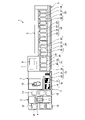
まず、実施形態に係る基板処理装置1の構成について図1を参照して説明する。図1は、基板処理装置1の概略平面図である。なお、以下では、位置関係を明確にするために、互いに直交するX軸、Y軸およびZ軸を規定し、Z軸正方向を鉛直上向き方向とする。
<Configuration of substrate processing apparatus>
First, the configuration of a
図1に示すように、実施形態に係る基板処理装置1は、キャリア搬入出部2と、ロット形成部3と、ロット載置部4と、ロット搬送部5と、ロット処理部6と、制御部7とを有する。
As shown in FIG. 1, the
キャリア搬入出部2は、複数(たとえば、25枚)のウェハWを水平姿勢で上下に並べて収容したキャリア9の搬入、および搬出を行う。
The carrier loading/unloading
キャリア搬入出部2は、キャリアステージ10と、キャリア搬送機構11と、キャリアストック12、13と、キャリア載置台14とを有する。キャリアステージ10は、外部から搬送された複数のキャリア9を載置する。
The carrier loading/
キャリア搬送機構11は、キャリアステージ10と、キャリアストック12、13と、キャリア載置台14との間でキャリア9の搬送を行う。キャリアストック12、13は、キャリア9を一時的に保管する。
The
キャリアストック12は、ロット処理部6で処理される前の複数のウェハWを収容するキャリア9を一時的に保管する。キャリアストック13は、ロット処理部6で処理された複数のウェハWを収容するキャリア9を一時的に保管する。
キャリア載置台14に載置されたキャリア9からは、処理される前の複数のウェハWが後述する基板搬送機構15によりロット処理部6に搬出される。また、キャリア載置台14に載置されたキャリア9には、処理された複数のウェハWが基板搬送機構15によりロット処理部6から搬入される。
From the
処理された複数のウェハWを収容するキャリア9のうち、キャリアステージ10に搬送されたキャリア9は、外部へ搬出される。
Of the
ロット形成部3は、基板搬送機構15を有し、ロットを形成する。このロットは、1または複数のキャリア9に収容されたウェハWを組合せて同時に処理される複数(たとえば、50枚)のウェハWで構成される。
The
なお、ロット形成部3でロットを形成する際には、ウェハWの表面にパターンが形成されている面が互いに向かい合うようにロットを形成してもよく、また、ウェハWの表面にパターンが形成されている面がすべて一方を向くようにロットを形成してもよい。
When forming lots in the
基板搬送機構15は、複数のウェハWを搬送する。基板搬送機構15は、ウェハWの搬送途中でウェハWの姿勢を水平姿勢から垂直姿勢および垂直姿勢から水平姿勢に変更させることができる。
The
基板搬送機構15は、キャリア載置台14に載置されたキャリア9からロット載置部4にウェハWを搬送する。また、基板搬送機構15は、ロット載置部4からキャリア載置台14に載置されたキャリア9にウェハWを搬送する。
The
なお、基板搬送機構15は、複数のウェハWを支持する基板支持部として、処理される前のウェハWを支持する処理前基板支持部と、処理されたウェハWを支持する処理後基板支持部との2種類を有する。これにより、処理される前のウェハWなどに付着したパーティクルなどが処理されたウェハWに転着することを抑制することができる。
The
ロット載置部4は、ロット搬送台16を有し、ロット搬送部5によってロット形成部3とロット処理部6との間で搬送されるロットを一時的に載置(待機)する。ロット搬送台16は、搬入側ロット載置台17と、搬出側ロット載置台18とを有する。
The
搬入側ロット載置台17には、ロット形成部3で形成された処理される前のロットが載置される。搬出側ロット載置台18には、ロット処理部6で処理されたロットが載置される。かかる搬入側ロット載置台17および搬出側ロット載置台18には、1ロット分の複数のウェハWが垂直姿勢で前後に並んで載置される。
A lot formed by the
ロット搬送部5は、ロット搬送機構19を有し、ロット載置部4とロット処理部6との間やロット処理部6の内部でロットの搬送を行う。ロット搬送機構19は、レール20と、移動体21と、基板保持体22とを有する。
The
レール20は、ロット載置部4およびロット処理部6に渡って、X軸方向に沿って配置されている。移動体21は、複数のウェハWを保持しながらレール20に沿って移動可能に構成される。基板保持体22は、移動体21に設けられ、垂直姿勢で前後に並んだ複数のウェハWを保持する。
The
そして、ロット搬送部5は、搬入側ロット載置台17に載置されたロットをロット処理部6に搬送する。また、ロット搬送部5は、ロット処理部6で処理されたロットを搬出側ロット載置台18に搬送する。さらに、ロット搬送部5は、ロット処理部6の内部でロットを搬送する。
The
ロット処理部6は、垂直姿勢で前後に並んだ複数のウェハWを1ロットとして、エッチング処理や洗浄処理、乾燥処理などを行う。ロット処理部6には、2台のエッチング処理装置23と、洗浄処理装置24と、基板保持体洗浄処理装置25と、乾燥処理装置26とが、レール20に沿って並んで設けられる。
The
エッチング処理装置23は、ロットのエッチング処理を行う。洗浄処理装置24は、ロットの洗浄処理を行う。基板保持体洗浄処理装置25は、基板保持体22の洗浄処理を行う。乾燥処理装置26は、ロットの乾燥処理を行う。なお、エッチング処理装置23、洗浄処理装置24、基板保持体洗浄処理装置25および乾燥処理装置26の台数は、図1の例に限られない。
The
エッチング処理装置23は、エッチング用の処理槽27と、リンス用の処理槽28と、基板昇降機構29、30とを有する。処理槽27は、処理部の一例である。処理槽27には、エッチング用の処理液(以下、「エッチング液」とも呼称する。)が貯留される。処理槽27の詳細については後述する。
The
処理槽28には、リンス用の処理液(純水等)が貯留される。基板昇降機構29、30には、ロットを形成する複数のウェハWが垂直姿勢で前後に並んで保持される。
The
エッチング処理装置23は、ロット搬送部5で搬送されたロットを基板昇降機構29で保持し、処理槽27のエッチング液に浸漬させてエッチング処理を行う。エッチング処理は、たとえば、1時間~3時間程度行われる。
The
処理槽27でエッチング処理されたロットは、ロット搬送部5で処理槽28に搬送される。そして、エッチング処理装置23は、搬送されたロットを基板昇降機構30で保持し、処理槽28のリンス液に浸漬させてリンス処理を行う。処理槽28でリンス処理されたロットは、ロット搬送部5で洗浄処理装置24の処理槽31に搬送される。
The lot etched in the
洗浄処理装置24は、洗浄用の処理槽31と、リンス用の処理槽32と、基板昇降機構33、34とを有する。洗浄用の処理槽31には、洗浄用の処理液(たとえば、SC-1(アンモニア、過酸化水素および水の混合液)など)が貯留される。
The cleaning
リンス用の処理槽32には、リンス用の処理液(純水等)が貯留される。基板昇降機構33、34には、1ロット分の複数のウェハWが垂直姿勢で前後に並んで保持される。
A processing liquid for rinsing (pure water or the like) is stored in the
洗浄処理装置24は、ロット搬送部5で搬送されたロットを基板昇降機構33で保持し、処理槽31の洗浄液に浸漬させて洗浄処理を行う。
The
処理槽31で洗浄処理されたロットは、ロット搬送部5で処理槽32に搬送される。そして、洗浄処理装置24は、搬送されたロットを基板昇降機構34で保持し、処理槽32のリンス液に浸漬させてリンス処理を行う。処理槽32でリンス処理されたロットは、ロット搬送部5で乾燥処理装置26の処理槽35に搬送される。
The lot that has been cleaned in the
乾燥処理装置26は、処理槽35と、基板昇降機構36とを有する。処理槽35には、乾燥用の処理ガス(たとえば、IPA(イソプロピルアルコール)など)が供給される。基板昇降機構36には、1ロット分の複数のウェハWが垂直姿勢で前後に並んで保持される。
The drying
乾燥処理装置26は、ロット搬送部5で搬送されたロットを基板昇降機構36で保持し、処理槽35内に供給される乾燥用の処理ガスを用いて乾燥処理を行う。処理槽35で乾燥処理されたロットは、ロット搬送部5でロット載置部4に搬送される。
The drying
基板保持体洗浄処理装置25は、処理槽37を有し、かかる処理槽37に洗浄用の処理液や乾燥ガスを供給可能に構成される。そして、基板保持体洗浄処理装置25は、ロット搬送機構19の基板保持体22に洗浄用の処理液を供給し、さらに乾燥ガスを供給することで、基板保持体22の洗浄処理を行う。
The substrate holder
また、基板処理装置1には、ここまで説明した各部に加えて、リン酸水溶液供給源40a(図2参照)が設けられる。リン酸水溶液供給源40aは、処理液生成部の一例である。かかるリン酸水溶液供給源40aの詳細については後述する。
Further, the
制御部7は、基板処理装置1の各部(キャリア搬入出部2、ロット形成部3、ロット載置部4、ロット搬送部5、ロット処理部6、リン酸水溶液供給源40aなど)の動作を制御する。制御部7は、スイッチや各種センサなどからの信号に基づいて、基板処理装置1の各部の動作を制御する。
The
この制御部7は、たとえばコンピュータであり、コンピュータで読み取り可能な記憶媒体8を有する。記憶媒体8には、基板処理装置1において実行される各種の処理を制御するプログラムが格納される。
This
制御部7は、記憶媒体8に記憶されたプログラムを読み出して実行することによって基板処理装置1の動作を制御する。なお、プログラムは、コンピュータによって読み取り可能な記憶媒体8に記憶されていたものであって、他の記憶媒体から制御部7の記憶媒体8にインストールされたものであってもよい。
The
コンピュータによって読み取り可能な記憶媒体8としては、たとえばハードディスク(HD)、フレキシブルディスク(FD)、コンパクトディスク(CD)、マグネットオプティカルディスク(MO)、メモリカードなどがある。
The computer-
<エッチング用の処理槽の構成>
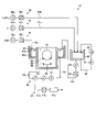
次に、エッチング用の処理槽27について、図2を参照しながら説明する。図2は、実施形態に係るエッチング用の処理槽27の構成を示す概略ブロック図である。
<Structure of Processing Tank for Etching>
Next, the
処理槽27では、所定のエッチング液を用いて、ウェハW上に形成されたシリコン窒化膜(SiN)およびシリコン酸化膜(SiO2)のうち、シリコン窒化膜を選択的にエッチングする。
In the
かかるシリコン窒化膜のエッチング処理では、リン酸(H3PO4)水溶液にシリコン(Si)含有化合物を添加してシリコン濃度を調整した溶液が、エッチング液として用いられる。 In such a silicon nitride film etching process, a solution obtained by adding a silicon (Si)-containing compound to a phosphoric acid (H 3 PO 4 ) aqueous solution to adjust the silicon concentration is used as an etchant.
エッチング液中のシリコン濃度を調整する手法としては、リン酸水溶液L(図3参照)にダミー基板を浸漬させてシリコンを溶解させる方法(シーズニング)や、コロイダルシリカなどのシリコン含有化合物をリン酸水溶液Lに溶解させる方法を用いることができる。また、リン酸水溶液Lにシリコン含有化合物水溶液を添加してシリコン濃度を調整してもよい。 As a method for adjusting the silicon concentration in the etchant, there is a method of immersing the dummy substrate in a phosphoric acid aqueous solution L (see FIG. 3) to dissolve silicon (seasoning), and a silicon-containing compound such as colloidal silica is added to the phosphoric acid aqueous solution. A method of dissolving in L can be used. Alternatively, the silicon concentration may be adjusted by adding a silicon-containing compound aqueous solution to the phosphoric acid aqueous solution L.
エッチング用の処理槽27は、リン酸水溶液供給部40と、シリコン供給部41と、DIW供給部42と、内槽44と、外槽45と、温調タンク46と、エッチング液排出部47とを有する。
The
リン酸水溶液供給部40は、リン酸水溶液供給源40aと、リン酸水溶液供給ライン40bと、流量調整器40cとを有する。
The phosphoric acid aqueous
リン酸水溶液供給源40aは、リン酸濃度が所望の濃度に濃縮されたリン酸水溶液Lを供給する。リン酸水溶液供給ライン40bは、リン酸水溶液供給源40aと温調タンク46とを接続し、リン酸水溶液供給源40aから温調タンク46にリン酸水溶液Lを供給する。
The phosphoric acid aqueous
流量調整器40cは、リン酸水溶液供給ライン40bに設けられ、温調タンク46へ供給されるリン酸水溶液Lの供給量を調整する。流量調整器40cは、開閉弁や流量制御弁、流量計などで構成される。
The
シリコン供給部41は、シリコン供給源41aと、シリコン供給ライン41bと、流量調整器41cとを有する。
The
シリコン供給源41aは、シリコン含有化合物水溶液を貯留するタンクである。シリコン供給ライン41bは、シリコン供給源41aと温調タンク46とを接続し、シリコン供給源41aから温調タンク46にシリコン含有化合物水溶液を供給する。
The
流量調整器41cは、シリコン供給ライン41bに設けられ、温調タンク46へ供給されるシリコン含有化合物水溶液の供給量を調整する。流量調整器41cは、開閉弁や流量制御弁、流量計などで構成される。流量調整器41cによってシリコン含有化合物水溶液の供給量が調整されることで、エッチング液のシリコン濃度が調整される。
The
なお、シリコン供給部41は、シリコン含有化合物水溶液を外槽45に供給可能に構成されてもよい。これにより、シリコン供給部41は、エッチング処理中にエッチング液中のシリコン濃度が低下した場合に、かかるエッチング液のシリコン濃度を直接調整することができる。
The
DIW供給部42は、DIW供給源42aと、DIW供給ライン42bと、流量調整器42cとを有する。DIW供給部42は、エッチング液を加熱することで蒸発した水分を補給するため、外槽45にDIW(DeIonized Water:脱イオン水)を供給する。
The
DIW供給ライン42bは、DIW供給源42aと外槽45とを接続し、DIW供給源42aから外槽45に所定温度のDIWを供給する。
The
流量調整器42cは、DIW供給ライン42bに設けられ、外槽45へ供給されるDIWの供給量を調整する。流量調整器42cは、開閉弁や流量制御弁、流量計などで構成される。流量調整器42cによってDIWの供給量が調整されることで、エッチング液の温度、リン酸濃度およびシリコン濃度が調整される。
The
内槽44は、上部が開放され、エッチング液が上部付近まで供給される。かかる内槽44では、基板昇降機構29で複数のウェハWがエッチング液に浸漬され、ウェハWにエッチング処理が行われる。
The
外槽45は、内槽44の上部周囲に設けられるとともに、上部が開放される。外槽45には、内槽44からオーバーフローしたエッチング液が流入する。また、外槽45には、温調タンク46から予備液が供給され、DIW供給部42からDIWが供給される。
The
外槽45には、温度センサ45aとリン酸濃度センサ45bとが設けられる。温度センサ45aは、エッチング液の温度を検出し、リン酸濃度センサ45bは、エッチング液のリン酸濃度を検出する。温度センサ45aおよびリン酸濃度センサ45bで生成された信号は、制御部7(図1参照)に送信される。
The
外槽45と内槽44とは、循環ライン50によって接続される。循環ライン50の一端は外槽45に接続され、循環ライン50の他端は内槽44内に設置された処理液供給ノズル49に接続される。
The
循環ライン50には、外槽45側から順に、ポンプ51と、ヒーター52と、フィルタ53と、シリコン濃度センサ54とが設けられる。
The
ポンプ51は、外槽45から循環ライン50を経て内槽44に送られるエッチング液の循環流を形成する。また、エッチング液は、内槽44からオーバーフローすることで、再び外槽45へと流出する。このようにして、エッチング液の循環路55が形成される。すなわち、循環路55は、外槽45、循環ライン50および内槽44によって形成される。
The
ヒーター52は、循環ライン50を循環するエッチング液の温度を調整する。循環路55では、内槽44を基準として外槽45がヒーター52よりも上流側に設けられる。
The
フィルタ53は、循環ライン50を循環するエッチング液を濾過する。シリコン濃度センサ54は、循環ライン50を循環するエッチング液中のシリコン濃度を検出する。シリコン濃度センサ54で生成された信号は、制御部7に送信される。
The
温調タンク46では、たとえば、内槽44および外槽45のエッチング液をすべて入れ替える場合に、リン酸水溶液Lとシリコン含有化合物水溶液とが混合された予備液が生成され、貯留される。また、温調タンク46では、たとえば、エッチング処理中にエッチング液の一部を入れ替える場合に、リン酸水溶液Lが予備液として貯留される。
In the
温調タンク46には、温調タンク46内の予備液を循環させる循環ライン60が接続される。循環ライン60には、ポンプ61およびヒーター62が設けられる。ポンプ61は、温調タンク46から循環ライン60を経て温調タンク46に戻る予備液の循環流を形成する。ヒーター62は、循環ライン60を循環する予備液の温度を調整する。
A
また、温調タンク46には、供給ライン63の一端が接続される。供給ライン63の他端は、外槽45に接続される。供給ライン63には、ポンプ64と、流量調整器65とが設けられる。
One end of a
ポンプ64は、温調タンク46から外槽45に予備液を流す。流量調整器65は、外槽45へ供給される予備液の供給量を調整する。流量調整器65は、開閉弁や流量制御弁、流量計などで構成される。流量調整器65によって予備液の供給量が調整されることで、エッチング液の温度、リン酸濃度およびシリコン濃度が調整される。
A
エッチング液排出部47は、エッチング処理で使用されたエッチング液の全部、または一部を入れ替える際にエッチング液を排出する。エッチング液排出部47は、排出ライン47aと、流量調整器47bと、冷却タンク47cとを有する。
The
排出ライン47aは、循環ライン50に接続される。流量調整器47bは、排出ライン47aに設けられ、排出されるエッチング液の排出量を調整する。流量調整器47bは、開閉弁や流量制御弁、流量計などから構成される。
The
冷却タンク47cは、排出ライン47aを流れてきたエッチング液を一時的に貯留するとともに冷却する。冷却タンク47cでは、流量調整器47bによってエッチング液の排出量が調整され、さらに純水が供給されることで、エッチング液の温度、リン酸濃度、シリコン濃度が調整される。
The
<リン酸水溶液供給源の詳細>
つづいて、実施形態に係る処理液生成部の一例であるリン酸水溶液供給源40aの詳細について、図3および図4を参照しながら説明する。図3および図4は、実施形態に係るリン酸水溶液供給源40aの構成を示す概略ブロック図である。なお、図3はタンク100を正面から見た場合の図面であり、図4はタンク100を側面から見た場合の図面である。
<Details of phosphoric acid aqueous solution supply source>
Next, the details of the phosphoric acid aqueous
図3に示すように、実施形態に係るリン酸水溶液供給源40aは、タンク100と、循環ライン110と、ノズル120と、バブリング機構130とを有する。タンク100は、貯留部の一例である。かかるタンク100には、リン酸供給部101と、DIW供給部102とが接続される。
As shown in FIG. 3, the phosphoric acid aqueous
リン酸供給部101は、リン酸供給源101aと、バルブ101bと、流量調整器101cを有し、リン酸供給源101aからバルブ101bおよび流量調整器101cを介してタンク100にリン酸水溶液Lを供給する。これにより、タンク100は、リン酸水溶液Lを貯留する。
The phosphoric
リン酸水溶液Lは、処理液の一例である。実施形態において、リン酸供給部101から供給されるリン酸水溶液Lは、たとえば、市販品でもっとも濃度の高い(たとえば、85wt%)リン酸水溶液である。
The phosphoric acid aqueous solution L is an example of the treatment liquid. In the embodiment, the phosphoric acid aqueous solution L supplied from the phosphoric
DIW供給部102は、DIW供給源102aと、バルブ102bと、流量調整器102cを有し、DIW供給源102aからバルブ102bおよび流量調整器102cを介してタンク100にDIWを供給する。なお、DIW供給源102aは、上述のDIW供給源42aと同じであってもよいし、異なっていてもよい。
The
また、タンク100の上部には、FFU(Fan Filter Unit)103と、吸気ダクト104と、排気ダクト105と、ミストトラップ106とが設けられる。FFU103は、吸気ダクト104、タンク100および排気ダクト105を流れるガスの流れFを形成する。
An FFU (Fan Filter Unit) 103 , an
すなわち、FFU103、吸気ダクト104および排気ダクト105によって、タンク100内にガスの流れFを形成する気流形成機構が構成される。かかる気流形成機構によって形成されるガスの流れFは、タンク100に貯留されるリン酸水溶液Lの液面Laに沿って流れる。
That is, the
ミストトラップ106は、排気ダクト105を介して排出される排気の中から、ガスとタンク100内で発生したミストとを分離する。
The
循環ライン110は、タンク100に貯留されるリン酸水溶液Lを循環させる。かかる循環ライン110は、タンク100の下方から出て、かかるタンク100の上方に戻る循環ラインである。
The
かかる循環ライン110には、タンク100を基準として、上流側から順にポンプ111と、フィルタ112と、ヒータ113と、開閉弁114とが設けられる。ヒータ113は、加熱部の一例である。
The
ポンプ111は、タンク100から出て、循環ライン110を通り、タンク100に戻るリン酸水溶液Lの循環流を形成する。フィルタ112は、循環ライン110内を循環するリン酸水溶液Lに含まれるパーティクルなどの汚染物質を除去する。なお、循環ライン110には、かかるフィルタ112をバイパスするバイパスライン115が設けられ、かかるバイパスライン115には、開閉弁116が設けられる。
Pump 111 forms a circulating flow of aqueous phosphoric acid solution L out of
ヒータ113は、循環ライン110内を循環するリン酸水溶液Lを加熱する。実施形態では、かかるヒータ113でリン酸水溶液Lを加熱することによって、タンク100に貯留されるリン酸水溶液Lを加熱する。これにより、タンク100に貯留されるリン酸水溶液L中の水分を蒸発させることができることから、かかるリン酸水溶液Lを所望の濃度(たとえば、90wt%以上)に濃縮させることができる。
The
たとえば、実施形態では、ヒータ113を制御することにより、タンク100に貯留されるリン酸水溶液Lを、かかるリン酸水溶液Lの沸点以上の温度(たとえば、170℃)に昇温するとよい。
For example, in the embodiment, the
また、循環ライン110には、ヒータ113と開閉弁114との間に分岐部117が設けられ、かかる分岐部117には上述のリン酸水溶液供給ライン40bが接続される。そして、リン酸水溶液供給ライン40bには、上述の流量調整器40cが設けられる。
Further, the
ノズル120は、循環ライン110の下流側に設けられ、タンク100に貯留されるリン酸水溶液Lの液面Laの上方から加熱されたリン酸水溶液Lを吐出する。かかるノズル120は、図4に示すように、水平方向に延在する。
The
また、ノズル120には、リン酸水溶液Lを吐出する複数の吐出口(図示せず)が水平方向に並んで設けられる。そして、ヒータ113で加熱されたリン酸水溶液Lが、かかる複数の吐出口から液面Laに向かって帯状に吐出される。
Further, the
このように、実施形態では、リン酸水溶液Lの濃縮処理において、加熱されたリン酸水溶液Lをノズル120からタンク100の内部に吐出する。これにより、タンク100内の雰囲気とリン酸水溶液Lとの間で形成される気液界面の面積を増加させることができる。
As described above, in the embodiment, the heated aqueous phosphoric acid solution L is discharged from the
したがって、実施形態によれば、リン酸水溶液L中の水分を効率よく蒸発させることができることから、リン酸水溶液Lを所望の濃度に効率よく濃縮させることができる。 Therefore, according to the embodiment, the water in the phosphoric acid aqueous solution L can be efficiently evaporated, so that the phosphoric acid aqueous solution L can be efficiently concentrated to a desired concentration.
また、実施形態では、循環ライン110の内部でポンプ111によって昇圧されたリン酸水溶液Lが、ノズル120から吐出される際に大気圧に急激に減圧される。そして、このように急激に減圧されると、リン酸水溶液Lの沸点が下がることから、リン酸水溶液Lからの水分の蒸発が促進される。
Further, in the embodiment, the phosphoric acid aqueous solution L pressurized by the
したがって、実施形態によれば、リン酸水溶液L中の水分をさらに効率よく蒸発させることができることから、リン酸水溶液Lを所望の濃度にさらに効率よく濃縮させることができる。 Therefore, according to the embodiment, the water content in the phosphoric acid aqueous solution L can be evaporated more efficiently, so that the phosphoric acid aqueous solution L can be more efficiently concentrated to a desired concentration.
また、実施形態では、図3および図4に示すように、ノズル120から吐出されるリン酸水溶液Lは、液面Laに向かって帯状に吐出されている。そして、気流形成機構によって形成されるガスの流れFは、かかる帯状のリン酸水溶液Lを貫くように、ノズル120と液面Laとの間を液面Laに沿うように流れている。
Further, in the embodiment, as shown in FIGS. 3 and 4, the phosphoric acid aqueous solution L discharged from the
このように、タンク100に貯留されるリン酸水溶液Lの液面Laに沿うようにガスの流れFを形成することにより、貯留されるリン酸水溶液Lからの水分の蒸発を促進することができる。したがって、実施形態によれば、リン酸水溶液Lを所望の濃度に効率よく濃縮させることができる。
Thus, by forming the gas flow F along the liquid surface La of the phosphoric acid aqueous solution L stored in the
また、ノズル120から吐出されるリン酸水溶液Lの周囲を流れるようにガスの流れFを形成することにより、吐出されるリン酸水溶液Lからの水分の蒸発を促進することができる。したがって、実施形態によれば、リン酸水溶液Lを所望の濃度に効率よく濃縮させることができる。
Further, by forming the gas flow F so as to flow around the phosphoric acid aqueous solution L discharged from the
なお、気流形成機構によって流れFを形成するガスは、基板処理装置1が設置されている環境の湿度より低い湿度であるとよい。これにより、リン酸水溶液Lからの水分の蒸発をさらに促進することができることから、リン酸水溶液Lを所望の濃度にさらに効率よく濃縮させることができる。
The humidity of the gas forming the flow F by the airflow forming mechanism is preferably lower than the humidity of the environment in which the
また、気流形成機構によって形成されるガスの流れFが帯状のリン酸水溶液Lを貫くように流れることにより、ガスと帯状のリン酸水溶液Lとの接触をさらに促進することができる。これにより、リン酸水溶液Lからの水分の蒸発をさらに促進することができることから、リン酸水溶液Lを所望の濃度にさらに効率よく濃縮させることができる。 In addition, the contact between the gas and the strip-shaped phosphoric acid aqueous solution L can be further promoted by causing the gas flow F formed by the airflow forming mechanism to flow through the strip-shaped phosphoric acid aqueous solution L. As a result, evaporation of water from the phosphoric acid aqueous solution L can be further accelerated, so that the phosphoric acid aqueous solution L can be more efficiently concentrated to a desired concentration.
なお、実施形態では、タンク100に上から順に第1液面センサS1~第4液面センサS4を設けることにより、液面Laの高さを制御している。これにより、タンク100の内部で液面Laがノズル120より高くなることを防止することができる。かかる第1液面センサS1~第4液面センサS4を用いた液面Laの制御については後述する。
In the embodiment, the height of the liquid level La is controlled by providing the
バブリング機構130は、タンク100に貯留されるリン酸水溶液LをバブリングガスBでバブリングする。かかるバブリング機構130は、バブリングガス供給源131と、バルブ132と、流量調整器133と、バブリングノズル134とを有する。
The bubbling
そして、バブリング機構130では、バブリングガス供給源131からバルブ132および流量調整器133を介してバブリングノズル134にバブリングガスBを供給する。バブリングノズル134は、たとえば、タンク100の底部に設けられ、水平方向に延在する。
The bubbling
また、バブリングノズル134には、バブリングガスBを吐出する複数の吐出口(図示せず)が水平方向に並んで設けられる。そして、かかる複数の吐出口からバブリングガスBが吐出されることにより、タンク100に貯留されるリン酸水溶液Lをバブリングすることができる。
Further, the bubbling
このように、実施形態では、タンク100に貯留されるリン酸水溶液LをバブリングガスBでバブリングすることにより、バブリングガスBとリン酸水溶液Lとの間で形成される気液界面の面積を増加させることができる。
Thus, in the embodiment, by bubbling the phosphoric acid aqueous solution L stored in the
したがって、実施形態によれば、リン酸水溶液L中の水分を効率よく蒸発させることができることから、リン酸水溶液Lを所望の濃度に効率よく濃縮させることができる。 Therefore, according to the embodiment, the water in the phosphoric acid aqueous solution L can be efficiently evaporated, so that the phosphoric acid aqueous solution L can be efficiently concentrated to a desired concentration.
なお、バブリングガスBは、基板処理装置1が設置されている環境の湿度より低い湿度であるとよい。これにより、リン酸水溶液Lからの水分の蒸発をさらに促進することができることから、リン酸水溶液Lを所望の濃度にさらに効率よく濃縮させることができる。
The bubbling gas B preferably has a humidity lower than the humidity of the environment in which the
また、実施形態では、図3に示すように、タンク100の底部全面に複数本のバブリングノズル134を配置するとよい。これにより、タンク100に貯留されるリン酸水溶液Lを全体的にバブリングすることができることから、リン酸水溶液Lを所望の濃度にさらに効率よく濃縮させることができる。
Moreover, in the embodiment, as shown in FIG. As a result, the entire phosphoric acid aqueous solution L stored in the
また、実施形態では、タンク100が閉構造であるとよい。すなわち、タンク100の上部が開放されず塞がれているとよい。これにより、タンク100に貯留されるリン酸水溶液Lが沸騰状態であったとしても、かかるリン酸水溶液Lがタンク100の外部に漏れ出すことを抑制することができる。
Further, in the embodiment, the
<リン酸水溶液濃縮処理の詳細>
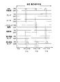
つづいては、実施形態に係るリン酸水溶液濃縮処理の詳細について、図5および図6を参照しながら説明する。図5は、実施形態に係るリン酸水溶液濃縮処理におけるリン酸水溶液供給源40aの各部の挙動パターンの具体例を示すタイミングチャートである。なお、かかるリン酸水溶液供給源40aの各部は、制御部7により制御される。
<Details of phosphoric acid aqueous solution concentration treatment>
Next, details of the phosphoric acid aqueous solution concentration process according to the embodiment will be described with reference to FIGS. 5 and 6. FIG. FIG. 5 is a timing chart showing a specific example of the behavior pattern of each part of the phosphoric acid aqueous
図5に示すように、実施形態に係るリン酸水溶液濃縮処理では、リン酸貯留工程と、温度・濃度調整処理と、供給準備処理とが順に実施される。まず、制御部7は、時間T0からリン酸供給部101を動作させる(ON状態にする)ことにより、リン酸貯留処理を開始する。
As shown in FIG. 5, in the phosphoric acid aqueous solution concentration process according to the embodiment, a phosphoric acid storage process, a temperature/concentration adjustment process, and a supply preparation process are sequentially performed. First, the
そして、タンク100に貯留されるリン酸水溶液Lの液面Laが徐々に上昇し、時間T1で液面Laが所定の第3高さ以上になると、第3液面センサS3からON信号が出力される。さらにリン酸水溶液Lの液面Laが上昇し、時間T2で液面Laが所定の第2高さ以上になると、第2液面センサS2からON信号が出力される。
Then, the liquid level La of the phosphoric acid aqueous solution L stored in the
このように、時間T2で、タンク100に貯留されるリン酸水溶液Lの液面Laが所定の第2高さになると、リン酸貯留処理が完了する。そして、かかる時間T2で、制御部7は、リン酸供給部101の動作を停止させる(OFF状態にする)。
Thus, when the liquid surface La of the phosphoric acid aqueous solution L stored in the
次に、制御部7は、温度・濃度調整処理を実施する。具体的には、制御部7は、時間T2からポンプ111とバブリング機構130とを動作させるとともに、バイパスライン115の開閉弁116を開状態にする(ON状態にする)。これにより、循環ライン110の内部をリン酸水溶液Lが循環するとともに、タンク100に貯留されるリン酸水溶液Lがバブリングされる。
Next, the
そして、制御部7は、循環ライン110内でリン酸水溶液Lが問題なく循環されていることを確認した後、時間T3でヒータ113を動作させる(ON状態にする)。これにより、循環ライン110で循環するリン酸水溶液Lを加熱することができることから、タンク100に貯留されるリン酸水溶液Lを加熱することができる。
Then, after confirming that the phosphoric acid aqueous solution L is circulating in the
なお、ヒータ113の設定温度は、タンク100内で濃縮処理されるリン酸水溶液Lの処理温度より高い温度(たとえば、200℃)にするとよい。また、実施形態におけるリン酸水溶液Lの加熱処理は、循環ライン110に設けられるヒータ113で実施される場合に限られず、タンク100の周囲や内部にヒータを設けることにより実施してもよい。すなわち、実施形態に係る加熱部は、ヒータ113に限られない。
The set temperature of the
一方で、リン酸水溶液Lの加熱処理を循環ライン110に設けられるヒータ113で実施することにより、リン酸水溶液Lを効率よく加熱することができることから、リン酸水溶液Lの濃縮処理を効率よく実施することができる。
On the other hand, since the phosphoric acid aqueous solution L can be efficiently heated by heating the phosphoric acid aqueous solution L with the
また、実施形態では、温度・濃度調整処理を開始する際に開閉弁116を開状態にすることにより、フィルタ112を介さずにバイパスライン115を介してリン酸水溶液Lを循環させる。
Further, in the embodiment, by opening the on-off
これにより、循環ライン110において、フィルタ112で発生する圧力損失を低減することができることから、加熱されたリン酸水溶液Lを効率よく循環させることができる。したがって、実施形態によれば、リン酸水溶液Lを効率よく加熱することができることから、リン酸水溶液Lの濃縮処理を効率よく実施することができる。
As a result, the pressure loss generated by the
なお、リン酸水溶液Lが所望の濃度に濃縮されるまでは、フィルタ112でリン酸水溶液Lを濾過する必要はないことから、バイパスライン115を介してリン酸水溶液Lを循環させたとしても特に問題はない。
Until the phosphoric acid aqueous solution L is concentrated to a desired concentration, it is not necessary to filter the phosphoric acid aqueous solution L with the
そして、タンク100に貯留されるリン酸水溶液Lが濃縮されるにしたがってリン酸水溶液Lの液面Laが低下し、時間T4で液面Laが所定の第2高さより低くなると、第2液面センサS2からOFF信号が出力される。
Then, as the phosphoric acid aqueous solution L stored in the
さらに、タンク100に貯留されるリン酸水溶液Lが濃縮され、時間T5で液面Laが所定の第3高さより低くなると、第3液面センサS3からOFF信号が出力される。この時点で、タンク100に貯留されるリン酸水溶液Lは、所望の濃度に濃縮される。このように、実施形態では、リン酸水溶液Lの濃縮処理を液面Laの高さで管理している。
Further, when the phosphoric acid aqueous solution L stored in the
そして、制御部7は、かかる時間T5で、バブリング機構130を停止させるとともに、バイパスライン115の開閉弁116を閉状態にする(OFF状態にする)。また、制御部7は、時間T5からリン酸供給部101を動作させる(ON状態にする)ことにより、タンク100にリン酸水溶液Lを補充する。
At this time T5, the
そして、タンク100に貯留されるリン酸水溶液Lの液面Laが上昇し、時間T6で液面Laが所定の第3高さ以上になると、第3液面センサS3からON信号が出力される。かかる時間T6で、制御部7は、リン酸供給部101の動作を停止させる(OFF状態にする)。
Then, the liquid level La of the phosphoric acid aqueous solution L stored in the
また、制御部7は、時間T5以降も引き続きポンプ111およびヒータ113を動作させて、ヒータ113で加熱されたリン酸水溶液Lをポンプ111で循環させる。さらに、時間T5から開閉弁116が閉状態になっていることから、制御部7は、循環ライン110で循環するリン酸水溶液Lをフィルタ112で濾過することができる。
Further, after time T5, the
そして、リン酸水溶液Lをフィルタ112で濾過する処理は、時間T5から所定の時間(たとえば、10分間)経過した時間T7まで実施される。実施形態では、かかる濾過処理によって、清浄なリン酸水溶液Lを生成することができる。このように、時間T7で、リン酸水溶液Lが所定の時間濾過されると、温度・濃度調整処理が完了する。
Then, the process of filtering the phosphoric acid aqueous solution L with the
なお、ここまで説明した温度・濃度調整処理では、所望の濃度にリン酸水溶液Lが濃縮された時点(すなわち、時間T5)から、バブリング機構130を停止させるとよい。これにより、タンク100に貯留されるリン酸水溶液Lが所望の濃度を超えて濃縮されることを抑制することができる。
In the temperature/concentration adjustment process described so far, the bubbling
また、温度・濃度調整処理では、所望の濃度にリン酸水溶液Lが濃縮された時点から、バブリング機構130を停止させる場合に限られず、バブリングガスBの流量を低下させてもよい。
In addition, in the temperature/concentration adjustment process, the flow rate of the bubbling gas B may be reduced without being limited to stopping the bubbling
次に、制御部7は、供給準備処理を実施する。具体的には、制御部7は、時間T7からヒータ113の動作を停止させる(OFF状態にする)。すなわち、供給準備処理では、ポンプ111のみが引き続き動作している。
Next, the
そして、かかる供給準備処理は、時間T7から所定の時間(たとえば、5分間)経過した時間T8まで実施される。このように、時間T7から所定の時間経過すると、供給準備処理が完了する。これにより、実施形態に係るリン酸水溶液濃縮処理が完了する。 This supply preparation process is performed until time T8 after a predetermined time (for example, 5 minutes) has elapsed from time T7. In this manner, the supply preparation process is completed after a predetermined time has elapsed from time T7. This completes the phosphoric acid aqueous solution concentration process according to the embodiment.
図6は、実施形態に係る温度・濃度維持処理におけるリン酸水溶液供給源40aの各部の挙動パターンの具体例を示すタイミングチャートである。かかる温度・濃度維持処理は、所望の濃度までリン酸水溶液Lが濃縮された後に、処理槽27でリン酸水溶液Lが使用されない場合に、リン酸水溶液Lを所望の濃度で維持するために実施される処理である。
FIG. 6 is a timing chart showing a specific example of the behavior pattern of each part of the phosphoric acid aqueous
図6に示すように、かかる温度・濃度調整処理において、制御部7は、ポンプ111およびヒータ113を動作させるとともに、開閉弁116を開状態にする(ON状態にする)。これにより、ヒータ113で加熱されたリン酸水溶液Lは、バイパスライン115を介して循環する。
As shown in FIG. 6, in the temperature/concentration adjustment process, the
そして、タンク100に貯留されるリン酸水溶液Lが濃縮され、時間T10で液面Laが所定の第3高さより低くなると、第3液面センサS3からOFF信号が出力される。
Then, when the phosphoric acid aqueous solution L stored in the
この場合、リン酸水溶液Lは所望の濃度を超えて濃縮されていることから、制御部7は、時間T10から所定の時間(たとえば、180秒)経過した時間T11で、DIW供給部102を動作させる(ON状態にする)。これにより、制御部7は、タンク100に貯留されるリン酸水溶液Lを所望の濃度に希釈する。
In this case, since the phosphoric acid aqueous solution L is concentrated beyond the desired concentration, the
このように、第3液面センサS3からOFF信号が出力された後、所定の時間経過してからDIW供給部102を動作させることにより、DIW供給部102の構成部品が過度に動作することを抑制することができる。
In this manner, by operating the
したがって、実施形態によれば、DIW供給部102の構成部品が過度に動作して、かかる構成部品に不具合が生じることを抑制することができる。
Therefore, according to the embodiment, it is possible to prevent the components of the
そして、タンク100に貯留されるリン酸水溶液Lの液面Laが上昇し、時間T12で液面Laが所定の第3高さ以上になると、第3液面センサS3からON信号が出力される。かかる時間T12で、制御部7は、DIW供給部102の動作を停止させる(OFF状態にする)。
Then, the liquid level La of the phosphoric acid aqueous solution L stored in the
以降においては、図6に示すように、液面Laの高さが所定の第3高さより低くなった都度、制御部7は、所定の時間経過した後にDIW供給部102を動作させてDIWを補充し、液面Laの高さを所定の第3高さに維持する。これにより、タンク100に貯留されるリン酸水溶液Lを所望の濃度で維持することができる。
After that, as shown in FIG. 6, every time the liquid level La becomes lower than a predetermined third height, the
なお、ここまで説明した温度・濃度維持処理では、バブリング機構130を停止させる(OFF状態にする)とよい。これにより、タンク100に貯留されるリン酸水溶液Lが所望の濃度を超えて濃縮されることを抑制することができる。
It should be noted that in the temperature/concentration maintenance process described so far, the bubbling
<変形例>
つづいては、実施形態の各種変形例について、図7~図9を参照しながら説明する。図7は、実施形態の変形例1に係るリン酸水溶液供給源40aの構成を示す概略ブロック図である。
<Modification>
Next, various modifications of the embodiment will be described with reference to FIGS. 7 to 9. FIG. FIG. 7 is a schematic block diagram showing the configuration of a phosphoric acid aqueous
図7に示すように、変形例1に係るリン酸水溶液供給源40aでは、タンク100の内部において、ノズル120とリン酸水溶液Lの液面Laとの間に板材121が設けられる。かかる板材121は、たとえば、互いの一部同士が重なるように複数設けられる。
As shown in FIG. 7 , in the phosphoric acid aqueous
そして、変形例1では、かかる板材121に向けてノズル120からリン酸水溶液Lが吐出される。このように、ノズル120から板材121を介してリン酸水溶液Lをタンク100内に吐出することにより、タンク100内の雰囲気とリン酸水溶液Lとの間で形成される気液界面の面積をさらに増加させることができる。
Then, in
したがって、変形例1によれば、リン酸水溶液L中の水分をさらに効率よく蒸発させることができることから、リン酸水溶液Lを所望の濃度にさらに効率よく濃縮させることができる。
Therefore, according to
また、変形例1では、互いの一部同士が重なるように板材121を複数設けることにより、リン酸水溶液Lが板材121に滞留する時間を長くすることができる。したがって、変形例1によれば、リン酸水溶液L中の水分をさらに効率よく蒸発させることができることから、リン酸水溶液Lを所望の濃度にさらに効率よく濃縮させることができる。
Further, in
図8は、実施形態の変形例2に係るリン酸水溶液供給源40aの構成を示す概略ブロック図である。図8に示すように、変形例2に係るリン酸水溶液供給源40aでは、ノズル120とリン酸水溶液Lの液面Laとの間に、板材121としてメッシュ板121Aが設けられる。
FIG. 8 is a schematic block diagram showing the configuration of a phosphoric acid aqueous
そして、変形例2では、かかるメッシュ板121Aに向けてノズル120からリン酸水溶液Lが吐出される。このように、ノズル120からメッシュ板121Aを介してリン酸水溶液Lをタンク100内に吐出することにより、タンク100内の雰囲気とリン酸水溶液Lとの間で形成される気液界面の面積をさらに増加させることができる。
Then, in
したがって、変形例2によれば、リン酸水溶液L中の水分をさらに効率よく蒸発させることができることから、リン酸水溶液Lを所望の濃度にさらに効率よく濃縮させることができる。
Therefore, according to
なお、上述の変形例1および変形例2では、板材121やメッシュ板121Aにヒータを取り付けて、かかるヒータで板材121やメッシュ板121Aを加熱してもよい。これにより、板材121やメッシュ板121Aに滞留するリン酸水溶液Lの蒸発を加速することができることから、リン酸水溶液Lを所望の濃度にさらに効率よく濃縮させることができる。
In addition, in the above-described modified examples 1 and 2, a heater may be attached to the
なお、図7の例では、板材121が複数設けられる例について示したが、板材121は1枚であってもよい。また、図8の例では、メッシュ板121Aが1枚設けられる例について示したが、メッシュ板121Aを複数設けてもよい。
In addition, in the example of FIG. 7 , an example in which a plurality of
図9は、実施形態の変形例3に係るリン酸水溶液供給源40aの構成を示す概略ブロック図である。図9に示すように、変形例3は、リン酸水溶液供給源40aが複数(図では2つ)設けられる供給源ユニット140が構成される例である。
FIG. 9 is a schematic block diagram showing the configuration of a phosphoric acid aqueous
かかる供給源ユニット140において、複数のリン酸水溶液供給源40aは、制御部7によりそれぞれ独立に動作させることができる。また、それぞれのリン酸水溶液供給源40aとリン酸水溶液供給ライン40bとの間には、バルブ141が設けられる。
In the
そして、変形例3では、制御部7が、少なくとも一つのリン酸水溶液供給源40aにおいてリン酸水溶液Lの濃縮処理を実施するとともに、他のリン酸水溶液供給源40aからは、所望の濃度に濃縮されたリン酸水溶液Lを処理槽27(図2参照)に供給する。
Then, in
このように、複数のリン酸水溶液供給源40aでリン酸水溶液Lの濃縮処理と供給処理とを並行して実施することにより、所望の濃度に濃縮されたリン酸水溶液Lを安定して処理槽27に供給することができる。したがって、変形例3によれば、ウェハWのエッチング処理を安定して実施することができる。
In this way, by performing the concentration treatment and the supply treatment of the phosphoric acid aqueous solution L in parallel with the plurality of phosphoric acid aqueous
なお、図9の例では、供給源ユニット140にリン酸水溶液供給源40aが2つ設けられた例について示したが、供給源ユニット140にはリン酸水溶液供給源40aが3つ以上設けられていてもよい。
In the example of FIG. 9, the
実施形態に係る基板処理装置1は、処理液(リン酸水溶液L)で基板(ウェハW)を処理する処理部(処理槽27)と、処理部に供給する処理液を生成する処理液生成部(リン酸水溶液供給源40a)とを備える。処理液生成部(リン酸水溶液供給源40a)は、貯留部(タンク100)と、循環ライン110と、加熱部(ヒータ113)と、ノズル120とを有する。貯留部(タンク100)は、処理液(リン酸水溶液L)を貯留する。循環ライン110は、貯留部(タンク100)に貯留される処理液(リン酸水溶液L)を循環させる。加熱部(ヒータ113)は、処理液(リン酸水溶液L)を加熱する。ノズル120は、循環ライン110の下流側に設けられ、貯留部(タンク100)に貯留される処理液(リン酸水溶液L)の液面La上方から加熱部(ヒータ113)で加熱された処理液を吐出する吐出口を有する。これにより、エッチング液の原料となるリン酸水溶液Lを所望の濃度に効率よく濃縮させることができる。
The
また、実施形態に係る基板処理装置1において、ノズル120は、水平方向に延在し、吐出口は、水平方向に複数並んで設けられる。これにより、ノズル120は、リン酸水溶液Lを帯状に吐出することができる。
Moreover, in the
また、実施形態に係る基板処理装置1において、ノズル120は、貯留部(タンク100)に貯留される処理液(リン酸水溶液L)の液面La上方に向けて処理液を吐出する。これにより、ノズル120から吐出されるリン酸水溶液Lをタンク100にムダなく貯留することができる。
Further, in the
また、実施形態に係る基板処理装置1は、ノズル120と、貯留部(タンク100)に貯留される処理液(リン酸水溶液L)の液面Laとの間にガスの流れFを形成する気流形成機構を備える。これにより、リン酸水溶液Lを所望の濃度に効率よく濃縮させることができる。
Further, the
また、実施形態に係る基板処理装置1において、ガスは、基板処理装置1が設置されている環境の湿度より低い湿度である。これにより、リン酸水溶液Lを所望の濃度にさらに効率よく濃縮させることができる。
Further, in the
また、実施形態に係る基板処理装置1において、ガスの流れFは、吐出口から吐出される帯状の処理液(リン酸水溶液L)を貫くように形成される。これにより、リン酸水溶液Lを所望の濃度にさらに効率よく濃縮させることができる。
Further, in the
また、実施形態に係る基板処理装置1は、ノズル120と、貯留部(タンク100)に貯留される処理液(リン酸水溶液L)の液面Laとの間に設けられる板材121を備える。また、ノズル120は、板材121に向けて処理液(リン酸水溶液L)を吐出する。これにより、リン酸水溶液Lを所望の濃度にさらに効率よく濃縮させることができる。
The
また、実施形態に係る基板処理装置1において、板材121は、一部が重なるように複数設けられる。これにより、リン酸水溶液Lを所望の濃度にさらに効率よく濃縮させることができる。
Moreover, in the
また、実施形態に係る基板処理装置1において、板材121は、メッシュ板121Aである。これにより、リン酸水溶液Lを所望の濃度にさらに効率よく濃縮させることができる。
Moreover, in the
また、実施形態に係る基板処理装置1は、貯留部(タンク100)に貯留される処理液(リン酸水溶液L)をバブリングするバブリング機構130を備える。これにより、リン酸水溶液Lを所望の濃度に効率よく濃縮させることができる。
Further, the
また、実施形態に係る基板処理装置1は、基板処理装置1を制御する制御部7を備える。そして、制御部7は、貯留部(タンク100)に貯留される処理液(リン酸水溶液L)が所定の状態になった場合に、バブリング機構130でバブリングされるバブリングガスBの流量を低下させる。これにより、タンク100に貯留されるリン酸水溶液Lが所望の濃度を超えて濃縮されることを抑制することができる。
Further, the
また、実施形態に係る基板処理装置1は、基板処理装置1を制御する制御部7を備える。循環ライン110は、処理液(リン酸水溶液L)を濾過するフィルタ112と、フィルタ112をバイパスするバイパスライン115と、バイパスライン115を開閉する開閉弁116とを有する。そして、制御部7は、貯留部(タンク100)に貯留される処理液(リン酸水溶液L)が所定の状態になるまでは、開閉弁116を開け、貯留部に貯留される処理液が所定の状態になった場合に、開閉弁116を閉める。これにより、リン酸水溶液Lの濃縮処理を効率よく実施することができる。
Further, the
また、実施形態に係る基板処理装置1において、処理液生成部(リン酸水溶液供給源40a)は、複数設けられる。そして、少なくとも一つの処理液生成部(リン酸水溶液供給源40a)は、処理液(リン酸水溶液L)を循環ライン110で循環させながら加熱部(ヒータ113)で加熱し、他の処理液生成部は、所定の状態になった処理液を処理部(処理槽27)に供給する。これにより、ウェハWのエッチング処理を安定して実施することができる。
Further, in the
実施形態に係る処理液濃縮方法は、循環工程と、加熱工程と、吐出工程とを含む。循環工程は、貯留部(タンク100)に貯留される処理液(リン酸水溶液L)を循環ライン110で循環させる。加熱工程は、処理液(リン酸水溶液L)を加熱する。吐出工程は、循環ライン110の下流側に設けられるノズル120によって、貯留部(タンク100)に貯留される処理液(リン酸水溶液L)の液面La上方から加熱工程で加熱された処理液を吐出する。これにより、エッチング液の原料となるリン酸水溶液Lを所望の濃度に効率よく濃縮させることができる。
A process liquid concentration method according to an embodiment includes a circulation process, a heating process, and a discharge process. In the circulation step, the processing liquid (phosphoric acid aqueous solution L) stored in the storage section (tank 100 ) is circulated through the
以上、本開示の実施形態について説明したが、本開示は上記の実施形態に限定されるものではなく、その趣旨を逸脱しない限りにおいて種々の変更が可能である。たとえば、上記の実施形態では、濃縮処理される処理液の一例としてリン酸水溶液を示したが、濃縮処理される処理液はリン酸水溶液に限られず、加熱することで濃縮させることができる処理液であればどのような処理液であってもよい。 Although the embodiments of the present disclosure have been described above, the present disclosure is not limited to the above-described embodiments, and various modifications can be made without departing from the scope of the present disclosure. For example, in the above embodiment, the phosphoric acid aqueous solution is shown as an example of the treatment liquid to be concentrated, but the treatment liquid to be concentrated is not limited to the phosphoric acid aqueous solution, and the treatment liquid can be concentrated by heating. Any processing liquid may be used.
今回開示された実施形態は全ての点で例示であって制限的なものではないと考えられるべきである。実に、上記した実施形態は多様な形態で具現され得る。また、上記の実施形態は、添付の特許請求の範囲及びその趣旨を逸脱することなく、様々な形態で省略、置換、変更されてもよい。 It should be considered that the embodiments disclosed this time are illustrative in all respects and not restrictive. Indeed, the above-described embodiments may be embodied in many different forms. Also, the above-described embodiments may be omitted, substituted, or modified in various ways without departing from the scope and spirit of the appended claims.
W ウェハ
1 基板処理装置
7 制御部
27 処理槽(処理部の一例)
40a リン酸水溶液供給源(処理液生成部の一例)
100 タンク(貯留部の一例)
110 循環ライン
112 フィルタ
113 ヒータ(加熱部の一例)
120 ノズル
121 板材
121A メッシュ板
130 バブリング機構
B バブリングガス
L リン酸水溶液(処理液の一例)
40a Phosphoric acid aqueous solution supply source (an example of a treatment liquid generation unit)
100 tank (an example of a reservoir)
110
120
Claims (14)
前記処理部に供給する前記処理液を生成する処理液生成部と、
を備え、
前記処理液生成部は、
前記処理液を貯留する貯留部と、
前記貯留部に貯留される前記処理液を循環させる循環ラインと、
前記処理液を加熱する加熱部と、
前記循環ラインの下流側に設けられ、前記貯留部に貯留される前記処理液の液面上方から前記加熱部で加熱された前記処理液を帯状に吐出する吐出口を有するノズルと、
を有する基板処理装置。 a processing unit that processes a substrate with a processing liquid;
a processing liquid generation unit that generates the processing liquid to be supplied to the processing unit;
with
The treatment liquid generation unit is
a reservoir for storing the treatment liquid;
a circulation line for circulating the processing liquid stored in the storage section;
a heating unit that heats the treatment liquid;
a nozzle provided on the downstream side of the circulation line and having a discharge port for discharging the processing liquid heated by the heating section from above the liquid surface of the processing liquid stored in the storage section;
A substrate processing apparatus having
前記吐出口は、水平方向に複数並んで設けられる
請求項1に記載の基板処理装置。 The nozzle extends horizontally,
The substrate processing apparatus according to claim 1 , wherein a plurality of the ejection ports are arranged horizontally.
請求項1または2に記載の基板処理装置。 3. The substrate processing apparatus according to claim 1, wherein the nozzle discharges the processing liquid upward from the surface of the processing liquid stored in the storage section.
請求項1~3のいずれか一つに記載の基板処理装置。 4. The substrate processing apparatus according to any one of claims 1 to 3, further comprising an airflow forming mechanism that forms a gas flow between the nozzle and the surface of the processing liquid stored in the storage section.
請求項4に記載の基板処理装置。 The substrate processing apparatus according to claim 4, wherein the gas has a humidity lower than the humidity of the environment in which the substrate processing apparatus is installed.
請求項4または5に記載の基板処理装置。 6. The substrate processing apparatus according to claim 4, wherein the flow of the gas is formed so as to penetrate the belt-like processing liquid discharged from the discharge port.
前記ノズルは、前記板材に向けて前記処理液を吐出する
請求項1~6のいずれか一つに記載の基板処理装置。 a plate provided between the nozzle and the liquid surface of the treatment liquid stored in the reservoir;
The substrate processing apparatus according to any one of claims 1 to 6, wherein the nozzle discharges the processing liquid toward the plate member.
請求項7に記載の基板処理装置。 The substrate processing apparatus according to claim 7, wherein a plurality of said plate members are provided so as to partially overlap each other.
請求項7または8に記載の基板処理装置。 The substrate processing apparatus according to claim 7 or 8, wherein the plate material is a mesh plate.
請求項1~9のいずれか一つに記載の基板処理装置。 The substrate processing apparatus according to any one of claims 1 to 9, further comprising a bubbling mechanism for bubbling the processing liquid stored in the storage section.
前記制御部は、前記貯留部に貯留される前記処理液が所定の状態になった場合に、前記バブリング機構でバブリングされるバブリングガスの流量を低下させる
請求項10に記載の基板処理装置。 A control unit that controls the substrate processing apparatus,
11. The substrate processing apparatus according to claim 10, wherein the control section reduces the flow rate of the bubbling gas bubbled by the bubbling mechanism when the processing liquid stored in the storage section reaches a predetermined state.
前記循環ラインは、前記処理液を濾過するフィルタと、前記フィルタをバイパスするバイパスラインと、前記バイパスラインを開閉する開閉弁とを有し、
前記制御部は、前記貯留部に貯留される前記処理液が所定の状態になるまでは、前記開閉弁を開け、前記貯留部に貯留される前記処理液が所定の状態になった場合に、前記開閉弁を閉める
請求項1~11のいずれか一つに記載の基板処理装置。 A control unit that controls the substrate processing apparatus,
The circulation line has a filter that filters the processing liquid, a bypass line that bypasses the filter, and an on-off valve that opens and closes the bypass line,
The control unit opens the on-off valve until the processing liquid stored in the storage unit reaches a predetermined state, and when the processing liquid stored in the storage unit reaches a predetermined state, The substrate processing apparatus according to any one of claims 1 to 11, wherein the on-off valve is closed.
少なくとも一つの前記処理液生成部は、前記処理液を前記循環ラインで循環させながら前記加熱部で加熱し、
他の前記処理液生成部は、所定の状態になった前記処理液を前記処理部に供給する
請求項1~12のいずれか一つに記載の基板処理装置。 A plurality of the treatment liquid generation units are provided,
At least one of the treatment liquid generators heats the treatment liquid with the heating part while circulating the treatment liquid in the circulation line,
The substrate processing apparatus according to any one of claims 1 to 12, wherein the other processing liquid generating section supplies the processing liquid in a predetermined state to the processing section.
前記処理液を加熱する加熱工程と、
前記循環ラインの下流側に設けられるノズルによって、前記貯留部に貯留される前記処理液の液面上方から前記加熱工程で加熱された前記処理液を帯状に吐出する吐出工程と、
を含む処理液濃縮方法。 a circulation step of circulating the treatment liquid stored in the storage part in a circulation line;
a heating step of heating the treatment liquid;
a discharging step of discharging the processing liquid heated in the heating step from above the liquid level of the processing liquid stored in the storage portion in a band shape from a nozzle provided downstream of the circulation line;
A process liquid concentration method comprising:
Priority Applications (4)
| Application Number | Priority Date | Filing Date | Title |
|---|---|---|---|
| JP2018232113A JP7190892B2 (en) | 2018-12-12 | 2018-12-12 | SUBSTRATE PROCESSING APPARATUS AND PROCESSING LIQUID CONCENTRATION METHOD |
| KR1020190163528A KR102706170B1 (en) | 2018-12-12 | 2019-12-10 | Substrate processing apparatus and processing liquid concentration method |
| US16/712,405 US11615971B2 (en) | 2018-12-12 | 2019-12-12 | Substrate processing apparatus and processing liquid concentration method |
| CN201911273652.1A CN111312619B (en) | 2018-12-12 | 2019-12-12 | Substrate processing device and processing liquid concentration method |
Applications Claiming Priority (1)
| Application Number | Priority Date | Filing Date | Title |
|---|---|---|---|
| JP2018232113A JP7190892B2 (en) | 2018-12-12 | 2018-12-12 | SUBSTRATE PROCESSING APPARATUS AND PROCESSING LIQUID CONCENTRATION METHOD |
Publications (2)
| Publication Number | Publication Date |
|---|---|
| JP2020096058A JP2020096058A (en) | 2020-06-18 |
| JP7190892B2 true JP7190892B2 (en) | 2022-12-16 |
Family
ID=71072915
Family Applications (1)
| Application Number | Title | Priority Date | Filing Date |
|---|---|---|---|
| JP2018232113A Active JP7190892B2 (en) | 2018-12-12 | 2018-12-12 | SUBSTRATE PROCESSING APPARATUS AND PROCESSING LIQUID CONCENTRATION METHOD |
Country Status (4)
| Country | Link |
|---|---|
| US (1) | US11615971B2 (en) |
| JP (1) | JP7190892B2 (en) |
| KR (1) | KR102706170B1 (en) |
| CN (1) | CN111312619B (en) |
Families Citing this family (13)
| Publication number | Priority date | Publication date | Assignee | Title |
|---|---|---|---|---|
| JP7190892B2 (en) * | 2018-12-12 | 2022-12-16 | 東京エレクトロン株式会社 | SUBSTRATE PROCESSING APPARATUS AND PROCESSING LIQUID CONCENTRATION METHOD |
| KR102759372B1 (en) * | 2019-01-08 | 2025-01-24 | 삼성전자주식회사 | Etchant composition for silicon nitride and method of fabricating semiconductor device |
| US11168978B2 (en) | 2020-01-06 | 2021-11-09 | Tokyo Electron Limited | Hardware improvements and methods for the analysis of a spinning reflective substrates |
| WO2021183332A1 (en) | 2020-03-10 | 2021-09-16 | Tokyo Electron Limited | Long wave infrared thermal sensor for integration into track system |
| JP7413113B2 (en) * | 2020-03-24 | 2024-01-15 | 株式会社Screenホールディングス | Processing liquid temperature control method, substrate processing method, processing liquid temperature control device, and substrate processing system |
| US20240192111A1 (en) * | 2021-04-01 | 2024-06-13 | Tokyo Electron Limited | Substrate liquid-treatment device |
| US11738363B2 (en) | 2021-06-07 | 2023-08-29 | Tokyo Electron Limited | Bath systems and methods thereof |
| JP7748237B2 (en) * | 2021-09-21 | 2025-10-02 | 株式会社Screenホールディングス | Substrate Processing Equipment |
| KR102858828B1 (en) * | 2021-12-14 | 2025-09-12 | 세메스 주식회사 | Apparatus and method for treating a substrate |
| TWI837779B (en) | 2022-03-16 | 2024-04-01 | 日商鎧俠股份有限公司 | Substrate processing equipment |
| WO2024004725A1 (en) * | 2022-07-01 | 2024-01-04 | 東京エレクトロン株式会社 | Substrate treatment apparatus and substrate treatment method |
| JP2024011180A (en) * | 2022-07-14 | 2024-01-25 | 株式会社ダルトン | Cleaning tank, cleaning system and cleaning method |
| JP7809615B2 (en) * | 2022-09-13 | 2026-02-02 | キオクシア株式会社 | Substrate processing apparatus, substrate processing method, and semiconductor device manufacturing method |
Citations (10)
| Publication number | Priority date | Publication date | Assignee | Title |
|---|---|---|---|---|
| JP2003525526A (en) | 2000-02-29 | 2003-08-26 | アドバンスド.テクノロジー.マテリアルス.インコーポレイテッド | An air management system and method for storing chemicals and reducing contamination in semiconductor manufacturing facilities. |
| JP2006186065A (en) | 2004-12-27 | 2006-07-13 | Matsushita Electric Ind Co Ltd | Electronic device cleaning apparatus and electronic device manufacturing method |
| JP2007273791A (en) | 2006-03-31 | 2007-10-18 | Dainippon Screen Mfg Co Ltd | Substrate processing apparatus and substrate processing method |
| JP2008098444A (en) | 2006-10-12 | 2008-04-24 | Apprecia Technology Inc | Etching solution regeneration method, etching method and etching apparatus |
| JP2009272548A (en) | 2008-05-09 | 2009-11-19 | Dainippon Screen Mfg Co Ltd | Substrate treatment apparatus |
| JP2011198895A (en) | 2010-03-18 | 2011-10-06 | Dainippon Screen Mfg Co Ltd | Substrate processing apparatus and substrate processing method |
| JP2014056936A (en) | 2012-09-12 | 2014-03-27 | Dainippon Screen Mfg Co Ltd | Chemical liquid supply device, substrate processing system, and substrate processing method |
| JP2017208418A (en) | 2016-05-17 | 2017-11-24 | 東京エレクトロン株式会社 | Substrate liquid processing apparatus, tank cleaning method, and storage medium |
| JP2018117032A (en) | 2017-01-18 | 2018-07-26 | 株式会社Screenホールディングス | Substrate processing apparatus |
| WO2018168874A1 (en) | 2017-03-15 | 2018-09-20 | 株式会社 東芝 | Etching solution, etching method and method for manufacturing electronic component |
Family Cites Families (30)
| Publication number | Priority date | Publication date | Assignee | Title |
|---|---|---|---|---|
| NL6608226A (en) * | 1965-06-18 | 1966-12-19 | ||
| GB1585855A (en) * | 1977-03-30 | 1981-03-11 | Hitachi Plant Eng & Constr Co | Method and apparatus for crystallisation of solution containing salts |
| JPH065505A (en) * | 1992-06-24 | 1994-01-14 | Nec Corp | Equipment for treatment before application of photoresist |
| TW333658B (en) * | 1996-05-30 | 1998-06-11 | Tokyo Electron Co Ltd | The substrate processing method and substrate processing system |
| US6399517B2 (en) * | 1999-03-30 | 2002-06-04 | Tokyo Electron Limited | Etching method and etching apparatus |
| JP4739142B2 (en) * | 2006-07-28 | 2011-08-03 | 東京エレクトロン株式会社 | Chemical processing apparatus, chemical supply method, and chemical supply program |
| KR100882910B1 (en) * | 2007-07-19 | 2009-02-10 | 삼성모바일디스플레이주식회사 | Etching Device |
| GB2461740B (en) * | 2008-06-23 | 2012-09-19 | Operational Group Ltd | Improvements in and relating to the processing of solvents and/or volatile components or the like |
| KR100991745B1 (en) * | 2008-10-17 | 2010-11-04 | 세메스 주식회사 | Treatment liquid supply device and its high temperature treatment liquid supply method |
| JP5412218B2 (en) * | 2009-09-08 | 2014-02-12 | 株式会社テックインテック | Substrate processing equipment |
| US20120247504A1 (en) * | 2010-10-01 | 2012-10-04 | Waleed Nasr | System and Method for Sub-micron Level Cleaning of Surfaces |
| JP6087063B2 (en) | 2012-05-01 | 2017-03-01 | 東京エレクトロン株式会社 | Etching method, etching apparatus and storage medium |
| JP5652456B2 (en) * | 2012-10-02 | 2015-01-14 | トヨタ自動車株式会社 | Temperature control system and method for estimating the amount of foreign matter clogging |
| JP6061378B2 (en) * | 2012-11-05 | 2017-01-18 | 株式会社Screenホールディングス | Substrate processing equipment |
| JP6352385B2 (en) * | 2013-03-15 | 2018-07-04 | ティーイーエル エフエスアイ,インコーポレイティド | Processing system and method for providing a heated etching solution |
| JP6179192B2 (en) * | 2013-05-27 | 2017-08-16 | 宇部興産株式会社 | Concentrated solution manufacturing method and solution concentration container |
| JP6502633B2 (en) * | 2013-09-30 | 2019-04-17 | 芝浦メカトロニクス株式会社 | Substrate processing method and substrate processing apparatus |
| KR102340465B1 (en) * | 2014-03-11 | 2021-12-16 | 가부시키가이샤 스크린 홀딩스 | Substrate treatment apparatus and substrate treatment method |
| TWI630652B (en) * | 2014-03-17 | 2018-07-21 | SCREEN Holdings Co., Ltd. | Substrate processing apparatus and substrate processing method using substrate processing apparatus |
| KR101671118B1 (en) * | 2014-07-29 | 2016-10-31 | 가부시키가이샤 스크린 홀딩스 | Substrate processing apparatus and substrate processing method |
| JP6359925B2 (en) * | 2014-09-18 | 2018-07-18 | 株式会社Screenホールディングス | Substrate processing equipment |
| JP6356091B2 (en) * | 2015-04-16 | 2018-07-11 | 東京エレクトロン株式会社 | Substrate liquid processing apparatus, heater unit control method, and storage medium |
| JP6732546B2 (en) * | 2016-06-09 | 2020-07-29 | 東京エレクトロン株式会社 | Substrate liquid processing apparatus, substrate liquid processing method and storage medium |
| JP6808423B2 (en) * | 2016-09-28 | 2021-01-06 | 東京エレクトロン株式会社 | Substrate processing equipment and processing liquid supply method |
| JP6857526B2 (en) * | 2017-03-27 | 2021-04-14 | 株式会社Screenホールディングス | Substrate processing equipment and substrate processing method |
| JP6379253B2 (en) * | 2017-05-09 | 2018-08-22 | 株式会社東京精密 | Prober |
| JP6924614B2 (en) * | 2017-05-18 | 2021-08-25 | 株式会社Screenホールディングス | Board processing equipment |
| JP6735718B2 (en) * | 2017-09-28 | 2020-08-05 | 東京エレクトロン株式会社 | Substrate processing apparatus, substrate processing method and program |
| JP6516908B2 (en) * | 2018-07-03 | 2019-05-22 | 東京エレクトロン株式会社 | Etching processing control apparatus using phosphoric acid aqueous solution, etching processing control method using phosphoric acid aqueous solution, and computer readable storage medium storing program for etching substrate with phosphoric acid aqueous solution |
| JP7190892B2 (en) * | 2018-12-12 | 2022-12-16 | 東京エレクトロン株式会社 | SUBSTRATE PROCESSING APPARATUS AND PROCESSING LIQUID CONCENTRATION METHOD |
-
2018
- 2018-12-12 JP JP2018232113A patent/JP7190892B2/en active Active
-
2019
- 2019-12-10 KR KR1020190163528A patent/KR102706170B1/en active Active
- 2019-12-12 US US16/712,405 patent/US11615971B2/en active Active
- 2019-12-12 CN CN201911273652.1A patent/CN111312619B/en active Active
Patent Citations (10)
| Publication number | Priority date | Publication date | Assignee | Title |
|---|---|---|---|---|
| JP2003525526A (en) | 2000-02-29 | 2003-08-26 | アドバンスド.テクノロジー.マテリアルス.インコーポレイテッド | An air management system and method for storing chemicals and reducing contamination in semiconductor manufacturing facilities. |
| JP2006186065A (en) | 2004-12-27 | 2006-07-13 | Matsushita Electric Ind Co Ltd | Electronic device cleaning apparatus and electronic device manufacturing method |
| JP2007273791A (en) | 2006-03-31 | 2007-10-18 | Dainippon Screen Mfg Co Ltd | Substrate processing apparatus and substrate processing method |
| JP2008098444A (en) | 2006-10-12 | 2008-04-24 | Apprecia Technology Inc | Etching solution regeneration method, etching method and etching apparatus |
| JP2009272548A (en) | 2008-05-09 | 2009-11-19 | Dainippon Screen Mfg Co Ltd | Substrate treatment apparatus |
| JP2011198895A (en) | 2010-03-18 | 2011-10-06 | Dainippon Screen Mfg Co Ltd | Substrate processing apparatus and substrate processing method |
| JP2014056936A (en) | 2012-09-12 | 2014-03-27 | Dainippon Screen Mfg Co Ltd | Chemical liquid supply device, substrate processing system, and substrate processing method |
| JP2017208418A (en) | 2016-05-17 | 2017-11-24 | 東京エレクトロン株式会社 | Substrate liquid processing apparatus, tank cleaning method, and storage medium |
| JP2018117032A (en) | 2017-01-18 | 2018-07-26 | 株式会社Screenホールディングス | Substrate processing apparatus |
| WO2018168874A1 (en) | 2017-03-15 | 2018-09-20 | 株式会社 東芝 | Etching solution, etching method and method for manufacturing electronic component |
Also Published As
| Publication number | Publication date |
|---|---|
| US11615971B2 (en) | 2023-03-28 |
| JP2020096058A (en) | 2020-06-18 |
| KR20200072419A (en) | 2020-06-22 |
| CN111312619B (en) | 2024-09-10 |
| US20200194280A1 (en) | 2020-06-18 |
| CN111312619A (en) | 2020-06-19 |
| KR102706170B1 (en) | 2024-09-13 |
Similar Documents
| Publication | Publication Date | Title |
|---|---|---|
| JP7190892B2 (en) | SUBSTRATE PROCESSING APPARATUS AND PROCESSING LIQUID CONCENTRATION METHOD | |
| JP7756761B2 (en) | Substrate Processing System | |
| JP7158249B2 (en) | SUBSTRATE PROCESSING METHOD, SUBSTRATE PROCESSING APPARATUS, AND STORAGE MEDIUM | |
| KR102560934B1 (en) | Substrate processing apparatus, substrate processing method and recording medium | |
| KR20210064061A (en) | Substrate processing apparatus and substrate processing method | |
| JP6434367B2 (en) | Substrate liquid processing apparatus, substrate liquid processing method, and computer readable storage medium storing substrate liquid processing program | |
| JP2022057798A (en) | Substrate processing system and substrate conveyance method | |
| JP2018014470A (en) | Substrate liquid processing apparatus, substrate liquid processing method, and storage medium | |
| JP7058701B2 (en) | Board processing equipment and board processing method | |
| CN100380602C (en) | Substrate processing method and substrate processing device | |
| KR20230133231A (en) | Substrate processing method and substrate processing system | |
| KR102677357B1 (en) | Substrate processing apparatus and processing liquid reuse method | |
| CN112687577B (en) | Substrate processing apparatus and apparatus cleaning method | |
| JP7418261B2 (en) | Substrate processing method and substrate processing apparatus | |
| JP6896129B2 (en) | Board processing equipment, board processing methods and programs | |
| JP2024079047A (en) | SUBSTRATE PROCESSING APPARATUS AND SUBSTRATE PROCESSING METHOD |
Legal Events
| Date | Code | Title | Description |
|---|---|---|---|
| A621 | Written request for application examination |
Free format text: JAPANESE INTERMEDIATE CODE: A621 Effective date: 20210928 |
|
| A977 | Report on retrieval |
Free format text: JAPANESE INTERMEDIATE CODE: A971007 Effective date: 20220728 |
|
| A131 | Notification of reasons for refusal |
Free format text: JAPANESE INTERMEDIATE CODE: A131 Effective date: 20220816 |
|
| A521 | Request for written amendment filed |
Free format text: JAPANESE INTERMEDIATE CODE: A523 Effective date: 20220928 |
|
| TRDD | Decision of grant or rejection written | ||
| A01 | Written decision to grant a patent or to grant a registration (utility model) |
Free format text: JAPANESE INTERMEDIATE CODE: A01 Effective date: 20221108 |
|
| A61 | First payment of annual fees (during grant procedure) |
Free format text: JAPANESE INTERMEDIATE CODE: A61 Effective date: 20221206 |
|
| R150 | Certificate of patent or registration of utility model |
Ref document number: 7190892 Country of ref document: JP Free format text: JAPANESE INTERMEDIATE CODE: R150 |
|
| R250 | Receipt of annual fees |
Free format text: JAPANESE INTERMEDIATE CODE: R250 |