JP6497302B2 - Wiring member with mold part - Google Patents
Wiring member with mold part Download PDFInfo
- Publication number
- JP6497302B2 JP6497302B2 JP2015226525A JP2015226525A JP6497302B2 JP 6497302 B2 JP6497302 B2 JP 6497302B2 JP 2015226525 A JP2015226525 A JP 2015226525A JP 2015226525 A JP2015226525 A JP 2015226525A JP 6497302 B2 JP6497302 B2 JP 6497302B2
- Authority
- JP
- Japan
- Prior art keywords
- mold
- peripheral surface
- conductor
- mold part
- elastic annular
- Prior art date
- Legal status (The legal status is an assumption and is not a legal conclusion. Google has not performed a legal analysis and makes no representation as to the accuracy of the status listed.)
- Active
Links
Images


Classifications
-
- H—ELECTRICITY
- H01—ELECTRIC ELEMENTS
- H01R—ELECTRICALLY-CONDUCTIVE CONNECTIONS; STRUCTURAL ASSOCIATIONS OF A PLURALITY OF MUTUALLY-INSULATED ELECTRICAL CONNECTING ELEMENTS; COUPLING DEVICES; CURRENT COLLECTORS
- H01R4/00—Electrically-conductive connections between two or more conductive members in direct contact, i.e. touching one another; Means for effecting or maintaining such contact; Electrically-conductive connections having two or more spaced connecting locations for conductors and using contact members penetrating insulation
- H01R4/70—Insulation of connections
- H01R4/72—Insulation of connections using a heat shrinking insulating sleeve
-
- H—ELECTRICITY
- H01—ELECTRIC ELEMENTS
- H01B—CABLES; CONDUCTORS; INSULATORS; SELECTION OF MATERIALS FOR THEIR CONDUCTIVE, INSULATING OR DIELECTRIC PROPERTIES
- H01B7/00—Insulated conductors or cables characterised by their form
- H01B7/17—Protection against damage caused by external factors, e.g. sheaths or armouring
- H01B7/28—Protection against damage caused by moisture, corrosion, chemical attack or weather
- H01B7/282—Preventing penetration of fluid, e.g. water or humidity, into conductor or cable
-
- H—ELECTRICITY
- H01—ELECTRIC ELEMENTS
- H01R—ELECTRICALLY-CONDUCTIVE CONNECTIONS; STRUCTURAL ASSOCIATIONS OF A PLURALITY OF MUTUALLY-INSULATED ELECTRICAL CONNECTING ELEMENTS; COUPLING DEVICES; CURRENT COLLECTORS
- H01R4/00—Electrically-conductive connections between two or more conductive members in direct contact, i.e. touching one another; Means for effecting or maintaining such contact; Electrically-conductive connections having two or more spaced connecting locations for conductors and using contact members penetrating insulation
- H01R4/70—Insulation of connections
-
- H—ELECTRICITY
- H02—GENERATION; CONVERSION OR DISTRIBUTION OF ELECTRIC POWER
- H02G—INSTALLATION OF ELECTRIC CABLES OR LINES, OR OF COMBINED OPTICAL AND ELECTRIC CABLES OR LINES
- H02G15/00—Cable fittings
- H02G15/02—Cable terminations
- H02G15/04—Cable-end sealings
- H02G15/043—Cable-end sealings with end caps, e.g. sleeve closed at one end
- H02G15/046—Cable-end sealings with end caps, e.g. sleeve closed at one end with bores or protruding portions allowing passage of cable conductors
-
- H—ELECTRICITY
- H01—ELECTRIC ELEMENTS
- H01R—ELECTRICALLY-CONDUCTIVE CONNECTIONS; STRUCTURAL ASSOCIATIONS OF A PLURALITY OF MUTUALLY-INSULATED ELECTRICAL CONNECTING ELEMENTS; COUPLING DEVICES; CURRENT COLLECTORS
- H01R43/00—Apparatus or processes specially adapted for manufacturing, assembling, maintaining, or repairing of line connectors or current collectors or for joining electric conductors
- H01R43/20—Apparatus or processes specially adapted for manufacturing, assembling, maintaining, or repairing of line connectors or current collectors or for joining electric conductors for assembling or disassembling contact members with insulating base, case or sleeve
- H01R43/24—Assembling by moulding on contact members
Description
本発明は、モールド部を含むモールド部付配線部材に関する。 The present invention relates to a wiring member with a mold part including a mold part.
例えば、特許文献1には、導体と絶縁被覆とを備える絶縁電線の端部に端子が接続された端子付電線と、絶縁電線と端子との接続部を覆うモールド部と、を備えるモールド部付電線が示されている。 For example, Patent Document 1 includes a molded part including a terminal-attached electric wire having a terminal connected to an end of an insulated electric wire provided with a conductor and an insulating coating, and a mold part covering a connection part between the insulated electric wire and the terminal. Electric wires are shown.
しかしながら、特許文献1に示される例では、導体全体に亘って絶縁被覆が密着しているため、絶縁電線の柔軟性に乏しい。 However, in the example shown in Patent Document 1, since the insulation coating is in close contact over the entire conductor, the flexibility of the insulated wire is poor.
本発明は、モールド部を備える配線部材の配線部分の柔軟性を向上させることを目的とする。 An object of this invention is to improve the softness | flexibility of the wiring part of a wiring member provided with a mold part.
第1態様に係るモールド部付配線部材は、線状の導体部と、前記導体部の端部に接続された端子と、一端部側から前記端子が突出し、かつ、他端部側から前記導体部が延出するように前記導体部と前記端子との接続部分を覆うモールド部と、中間部で前記導体部との間に空隙が形成された状態で前記導体部の周囲を覆い、端部で前記モールド部の前記他端部と密着する被覆部材と、を備える。 The wiring member with a mold part according to the first aspect includes a linear conductor part, a terminal connected to an end part of the conductor part, the terminal projecting from one end part side, and the conductor from the other end part side A mold part that covers the connection part between the conductor part and the terminal so that the part extends, and an intermediate part that covers the periphery of the conductor part with a gap formed between the conductor part and an end part. And a covering member in close contact with the other end of the mold part.
第2態様に係るモールド部付配線部材は、第1態様に係るモールド部付配線部材の一態様である。第2態様に係るモールド部付配線部材においては、前記被覆部材の前記端部の外周面と前記モールド部の前記他端部の内周面とが密着している。 The wiring member with mold part according to the second aspect is one aspect of the wiring member with mold part according to the first aspect. In the wiring member with a mold part according to the second aspect, the outer peripheral surface of the end part of the covering member and the inner peripheral surface of the other end part of the mold part are in close contact.
第3態様に係るモールド部付配線部材は、第2態様に係るモールド部付配線部材の一態様である。第3態様に係るモールド部付配線部材は、前記被覆部材の前記端部の外周面と前記モールド部の前記他端部の内周面との間に設けられ、前記被覆部材の前記端部の外周面と前記モールド部の前記他端部の内周面とを密着させる第一接着剤をさらに備える。 The wiring member with mold part according to the third aspect is one aspect of the wiring member with mold part according to the second aspect. The wiring member with a mold according to the third aspect is provided between an outer peripheral surface of the end portion of the covering member and an inner peripheral surface of the other end portion of the mold portion, A first adhesive is further provided to bring the outer peripheral surface into close contact with the inner peripheral surface of the other end of the mold portion.
第4態様に係るモールド部付配線部材は、第1態様から第3態様のいずれか1つに係るモールド部付配線部材の一態様である。第4態様に係るモールド部付配線部材は、前記被覆部材の前記端部の内周面と前記導体部の外周面との間に設けられ、前記被覆部材の前記端部の内周面を前記導体部の外周面に密着させる第二接着剤をさらに備える。 The wiring member with a mold part according to the fourth aspect is one aspect of the wiring member with a mold part according to any one of the first to third aspects. The wiring member with a mold part according to a fourth aspect is provided between an inner peripheral surface of the end portion of the covering member and an outer peripheral surface of the conductor portion, and the inner peripheral surface of the end portion of the covering member is A second adhesive is further provided to be in close contact with the outer peripheral surface of the conductor portion.
第5態様に係るモールド部付配線部材は、第1態様に係るモールド部付配線部材の一態様である。第5態様に係るモールド部付配線部材においては、前記被覆部材は、前記端部に形成された弾性変形可能な部分であり前記モールド部の前記他端部の外周面に内周面が密着する弾性環状部を含む。 The wiring member with mold part according to the fifth aspect is one aspect of the wiring member with mold part according to the first aspect. In the wiring member with a mold part according to the fifth aspect, the covering member is an elastically deformable part formed at the end part, and the inner peripheral surface is in close contact with the outer peripheral surface of the other end part of the mold part. Includes an elastic annulus.
第6態様に係るモールド部付配線部材は、第5態様に係るモールド部付配線部材の一態様である。第6態様に係るモールド部付配線部材においては、前記モールド部には、係止部が形成され、前記弾性環状部のうち前記モールド部側を向く面を前記モールド部に押し付けるように接触する部分を含み、前記弾性環状部のうち前記モールド部側を向く面を前記モールド部に押し付けた状態で前記係止部に係止する被係止部が形成された固定部材をさらに備える。 The wiring member with mold part according to the sixth aspect is one aspect of the wiring member with mold part according to the fifth aspect. In the wiring member with a mold part according to the sixth aspect, a locking part is formed on the mold part, and a part of the elastic annular part that comes into contact with the mold part so as to press the surface facing the mold part side And a fixing member formed with a locked portion that is locked to the locking portion in a state in which a surface of the elastic annular portion facing the mold portion is pressed against the mold portion.
第7態様に係るモールド部付配線部材は、第5態様に係るモールド部付配線部材の一態様である。第7態様に係るモールド部付配線部材においては、前記モールド部には、係止部が形成され、前記弾性環状部のうち前記モールド部側を向く面を前記モールド部に押し付けた状態で前記係止部に係止する被係止部が、前記弾性環状部に形成されている。 The wiring member with mold part according to the seventh aspect is one aspect of the wiring member with mold part according to the fifth aspect. In the wiring member with a mold part according to a seventh aspect, the mold part is formed with a locking part, and the engagement part is pressed in a state where a surface of the elastic annular part facing the mold part side is pressed against the mold part. A locked portion that is locked to the locking portion is formed in the elastic annular portion.
上記の各態様では、被覆部材の中間部で導体部との間に空隙が形成されている。導体部は、モールド部付導電部材の配線部分である。従って、このモールド部付配線部材においては、配線部分の柔軟性に優れる。 In each of the above aspects, a gap is formed between the conductor portion and the intermediate portion of the covering member. A conductor part is a wiring part of a conductive member with a mold part . Therefore, in this wiring member with a mold part, the flexibility of the wiring part is excellent.
第2態様では、被覆部材の前記端部の外周面とモールド部の他端部の内周面とが密着するため、この間から液体が侵入することが抑制される。 In the second aspect, the outer peripheral surface of the end portion of the covering member and the inner peripheral surface of the other end portion of the mold portion are in close contact with each other.
第3態様では、被覆部材の端部の外周面とモールド部の他端部の内周面との間に設けられた第一接着剤によって、被覆部材の端部の外周面とモールド部の他端部の内周面との間から液体が侵入することがより確実に抑制される。 In the third aspect, the first adhesive provided between the outer peripheral surface of the end portion of the covering member and the inner peripheral surface of the other end portion of the mold portion allows the outer peripheral surface of the end portion of the covering member to Intrusion of liquid from between the inner peripheral surface of the end portion is more reliably suppressed.
第4態様では、被覆部材の端部の内周面と導体部の外周面との間に設けられた第二接着剤によって、モールド成形時にモールド部を構成するモールド樹脂が被覆部材の端部から内部に侵入することがより確実に抑制される。 In the fourth aspect, the second adhesive provided between the inner peripheral surface of the end portion of the covering member and the outer peripheral surface of the conductor portion causes the mold resin constituting the mold portion to be removed from the end portion of the covering member at the time of molding. Intrusion into the interior is more reliably suppressed.
第5態様では、弾性環状部の弾性力によって弾性環状部の内周面がモールド部の他端部の外周面に密着するため、弾性環状部の内周面とモールド部の他端部の外周面との間から液体が侵入することがより確実に抑制される。 In the fifth aspect, since the inner peripheral surface of the elastic annular portion is in close contact with the outer peripheral surface of the other end portion of the mold portion by the elastic force of the elastic annular portion, the outer periphery of the inner peripheral surface of the elastic annular portion and the other end portion of the mold portion Intrusion of liquid from between the surfaces is more reliably suppressed.
第6態様では、弾性環状部のうちモールド部側を向く面がモールド部に押し付けられるため、この間から液体が侵入することをより確実に抑制できる。即ち、止水性がより向上する。 In the sixth aspect, since the surface of the elastic annular portion that faces the mold portion is pressed against the mold portion, it is possible to more reliably prevent the liquid from entering from this point. That is, the water stoppage is further improved.
第7態様では、弾性環状部のうちモールド部側を向く面がモールド部に押し付けられるため、この間から液体が侵入することをより確実に抑制できる。即ち、止水性がより向上する。また、モールド部付配線部材を構成する部品点数の増大を抑制できる。 In the seventh aspect, since the surface of the elastic annular portion that faces the mold portion is pressed against the mold portion, it is possible to more reliably suppress the liquid from entering from this point. That is, the water stoppage is further improved. Moreover, the increase in the number of parts which comprise the wiring member with a mold part can be suppressed.
以下、添付の図面を参照しつつ、本発明の実施形態について説明する。以下の実施形態は、本発明を具現化した一例であり、本発明の技術的範囲を限定する事例ではない。 Hereinafter, embodiments of the present invention will be described with reference to the accompanying drawings. The following embodiment is an example embodying the present invention, and is not an example of limiting the technical scope of the present invention.
<第1実施形態>
はじめに、図1,2を参照しつつ、第1実施形態に係るモールド部付配線部材100について説明する。モールド部付配線部材100は、導体部9と端子8とモールド部3と被覆部材4とを備える。なお、ここでは、モールド部付配線部材100は、第一接着剤1と第二接着剤2とをさらに備えている。
<First Embodiment>
First, the
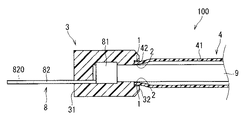
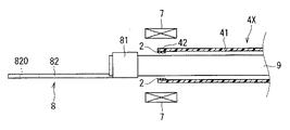
モールド部付配線部材100は、例えば、自動車等の車両に搭載される。図1は、第1実施形態に係るモールド部付配線部材100の側方断面図である。図2は、第1実施形態に係るモールド部付配線部材100の製造方法の一部を説明する説明図である。
The wiring member with
モールド部付配線部材100の各構成の詳細について説明する。まず、導体部9について説明する。
The detail of each structure of the
導体部9は、導電部材であり、例えば、銅又はアルミニウム等主成分とする金属の部材であることが考えられる。また、導体部9は、線状の部材である。導体部9は、例えば、複数の素線が撚り合わされて形成された撚り線である場合又は複数の素線が編まれて形成された編組線である場合等が考えられる。
The
次に端子8について説明する。モールド部付配線部材100においては、端子8は、導体部9の端部に接続されている。端子8は、例えば、銅等を主成分とする金属によって形成された部材である。
Next, the terminal 8 will be described. In the
ここでは、端子8は、導体接続部81と相手側接続部82とを備える。導体接続部81は、導体部9の端部が物理的に接続される部分である。ここでは、導体接続部81は、導体部9の端部に圧着可能な圧着片を含んでいる。そして、モールド部付配線部材100においては、導体接続部81の圧着片が導体部9の端部の周囲を覆う状態でかしめられて、導体接続部81と導体部9とが圧着されている。なお、他の例として、端子と導体部9とが超音波溶接等の溶接によって接続される場合も考えられる。この場合、端子の導体接続部は、例えば、導体部9の端部を溶接可能な平板状に形成されていることが考えられる。
Here, the terminal 8 includes a
また、相手側接続部82は、この端子8の接続相手である相手側部材に接続可能な部分である。ここでは、相手側接続部82には、相手側部材に対しボルト締結を可能にするボルト孔820が形成されている。なお、相手側部材としては、例えば、バッテリー又は金属ボディ(端子台)等が考えられる。
The
次に被覆部材4について説明する。被覆部材4は、中間部41で導体部9との間に空隙が形成された状態で導体部9の周囲を覆い、端部42でモールド部3の他端部32と密着する。
Next, the covering
ここで、被覆部材4が、端部42でモールド部3の他端部32と密着するとは、被覆部材4の端部42とモールド部3に他端部32との間に液体の侵入経路と成り得る隙間が形成されないように、被覆部材4の端部42とモールド部3の他端部32とが直接又は他の部材を介して間接的に接触していることを意味する。
Here, the covering
本実施形態では、被覆部材4の端部42が、モールド部3の他端部32に後述する第一接着剤1によって隙間なく接着されている。詳しくは、被覆部材4の端部42の外周面とモールド部3の他端部32の内周面との間の周方向全体に亘って設けられた第一接着剤1によって被覆部材4の端部42とモールド部3の他端部32とが接着されている。即ち、本実施形態は、第一接着剤1を介して被覆部材4の端部42が、モールド部3の他端部32に密着する場合の事例である。
In the present embodiment, the
しかしながら、他の例として、被覆部材が、第一接着剤を介さず端部でモールド部の他端部と隙間なく接触する場合も考えられる。 However, as another example, it may be considered that the covering member is in contact with the other end portion of the mold portion without a gap at the end portion without the first adhesive.
以下、本実施形態の被覆部材4の詳細について説明する。被覆部材4は、中間部41で導体部9との間に空隙が形成された状態で導体部9の周囲を覆う。ここでは、被覆部材4の延在方向全体に亘って中間部41と導体部9との間に空隙が形成されている。このため、中間部41の内径は、導体部9の外径よりも大きくなるように構成されていることが考えられる。
Hereinafter, the detail of the coating |
一方、図1に示されるように、ここでは、被覆部材4の端部42は、端部42の内周面が導体部9の外周面に密着するように導体部9の周囲を覆う。従って、ここでは、被覆部材4は、比較的内径の大きい中間部41と中間部41よりも内径の小さい端部42とを含んでいる。
On the other hand, as shown in FIG. 1, the
なお、被覆部材の端部が、中間部と同じように導体部との間に空隙が形成された状態で導体部の周囲を覆う場合も考えられる。この場合、例えば、被覆部材は、導体部の外径よりも大きい内径の中間部と、中間部の内径と同じ若しくはそれよりも大きい内径の端部と、を含んでいること等が考えられる。 In addition, the case where the edge part of a coating | coated member covers the circumference | surroundings of a conductor part in the state in which the space | gap was formed between the conductor parts similarly to the intermediate part is also considered. In this case, for example, it is conceivable that the covering member includes an intermediate portion having an inner diameter larger than the outer diameter of the conductor portion and an end portion having an inner diameter equal to or larger than the inner diameter of the intermediate portion.
ここで、被覆部材4の端部42の内周面が、導体部9の外周面に密着するとは、被覆部材4の端部42と導体部9との間に液体の侵入経路と成り得る隙間が形成されないように、被覆部材4の端部42と導体部9とが直接又は他の部材を介して間接的に接触していることを意味する。
Here, the fact that the inner peripheral surface of the
本実施形態では、被覆部材4の端部42が、後述する第二接着剤2によって導体部9に隙間なく接着されている。詳しくは、被覆部材4の端部42の内周面と導体部9の外周面との間の周方向全体に亘って設けられた第二接着剤2によって被覆部材4の端部42と導体部9とが接着されている。即ち、本実施形態は、第二接着剤2を介して被覆部材4の端部42が、導体部9に密着する場合の事例である。
In the present embodiment, the
しかしながら、他の例として、被覆部材の端部が、第二接着剤を介さず導体部と隙間なく接触する場合も考えられる。詳しくは後述する。 However, as another example, a case where the end portion of the covering member contacts the conductor portion without a gap without passing through the second adhesive may be considered. Details will be described later.
ここでは、被覆部材4は、一部が熱収縮した熱収縮チューブにより形成されている。熱収縮チューブは、熱を受けて収縮する熱収縮タイプのチューブである。熱収縮チューブは、例えば、ポリオレフィン系樹脂もしくはナイロン系樹脂などの合成樹脂によって形成された管状の部材である。熱収縮チューブは、押し出し成形によりごく細い管状に成形された樹脂部材が、架橋処理後、加熱された状態で太い管状へ引き伸ばされた後に冷却されることによって得られる。このようにして得られた熱収縮チューブは、加熱された場合、引き伸ばされる前の細い管状まで収縮する形状記憶特性を有する。
Here, the covering
また、ここでは、図2に示されるように、収縮前の熱収縮チューブ4Xの端部42の内周面には、熱可塑性の第二接着剤2が設けられている。なお、第二接着剤2は、収縮前の熱収縮チューブ4Xの端部42の内周面の周方向全体に亘って設けられていることが好ましい。第二接着剤2としては、例えば、変性オレフィン系又はポリエステル系のホットメルト接着剤などが採用されることが考えられる。
In addition, here, as shown in FIG. 2, the thermoplastic
本実施形態では、例えば、以下の手順で被覆部材4が得られる。まず、収縮前の熱収縮チューブ4Xの内部に導体部9が通される。なお、ここでは、導体部9の外径よりも内径が大きい収縮前の熱収縮チューブ4Xが採用される。そして、収縮前の熱収縮チューブ4Xの内部に導体部9が通された状態で、収縮前の熱収縮チューブ4Xのうち端部42のみがヒーター等の加熱部7によって加熱される。これにより、収縮前の熱収縮チューブ4Xのうち端部42のみが収縮する。そして、収縮した端部42の内周面は、第二接着剤2によって、導体部9の外周面に接着される。
In the present embodiment, for example, the covering
なお、他の例として、第二接着剤2が収縮前の熱収縮チューブ4Xの端部42の内周面に設けられておらず、熱収縮チューブ4X自身の収縮力によって端部42が、導体部9の外周面に隙間なく密着する場合等も考えられる。
As another example, the
一方、中間部41は加熱されず、収縮前の状態を保つ。このため、中間部41は、端部42が加熱された後も導体部9の外周面に接触せず、中間部41の内周面と導体部9の外周面との間に空隙が形成される。
On the other hand, the
次にモールド部3について説明する。モールド部3は、モールド部3の一端部31側から端子8が突出し、かつ、モールド部3の他端部32側から導体部9が延出するように導体部9と端子8との接続部分を覆う部材である。モールド部3は、例えば、PBT(ポリブチレンテレフタレート)樹脂、PPS(ポリフェニレンスルファイド)樹脂、PPA(ポリフタルアミド)樹脂、LCP樹脂(液晶ポリマー)、フェノール系、ポリエステル系、ポリアミド系又はエポキシ系の樹脂等により形成された部材であることが考えられる。
Next, the mold part 3 will be described. The mold part 3 is a connecting part between the
ここでは、モールド部3の他端部32が、被覆部材4の端部42の周囲を覆っている。そして、モールド部3の他端部32の内周面と被覆部材4の端部42の外周面との間には、第一接着剤1が設けられ、この第一接着剤1によってモールド部3の他端部32の内周面と被覆部材4の端部42の外周面とが接着されている。即ち、モールド部3の他端部32の内周面と被覆部材4の端部42の外周面とが密着している。なお、第一接着剤1は、例えば、ポリアミド系、変性オレフィン系又はポリエステル系等の接着剤である。
Here, the
以下、モールド部3を成形するモールド成形について説明する。本実施形態では、モールド成形の前に、被覆部材4によって導体部9の周囲を覆う工程が行われる。そして、被覆部材4の端部42の外周面に、第一接着剤1が塗布される等して設けられる。なお、第一接着剤1は、被覆部材4の端部42の外周面全周に亘って設けられることが好ましい。
Hereinafter, mold forming for forming the mold part 3 will be described. In this embodiment, the process of covering the circumference | surroundings of the
その後、被覆部材4によって周囲を覆われた導体部9と端子8との接続部分が、モールド成形が行われる金型の内部に配設される。ここでは、金型の内部には、被覆部材4の端部42から端子8の導体接続部81と相手側接続部82との間の部分までの領域が配設される。そして、金型の内部にモールド部3を形成するモールド樹脂を流し込み、このモールド樹脂が固化することで、端子8と導体部9との接続部分を覆うモールド部3が形成される。
Then, the connection part of the
そして、ここでは、モールド部3を形成するモールド樹脂が、被覆部材4の端部42の外周面に設けられた第一接着剤1によって被覆部材4の端部42の外周面に接着された状態で、即ち、モールド部3を形成するモールド樹脂が被覆部材4の端部42の外周面に密着した状態で固化する。このため、モールド部3と被覆部材4の端部42との間に液体の侵入経路と成り得る隙間が形成されることが抑制される。
Here, the mold resin forming the mold part 3 is adhered to the outer peripheral surface of the
<効果>
本実施形態のモールド部付配線部材100においては、被覆部材4の中間部41と導体部9との間に空隙が形成されているため、導体部9(即ち、モールド部付配線部材100の配線部分)を比較的容易に曲げることができる。従って、このモールド部付配線部材100においては、配線部分の柔軟性に優れる。
<Effect>
In the wiring member with
また、本実施形態では、被覆部材4の端部42の外周面とモールド部3の他端部32の内周面との間に設けられた第一接着剤1によって、被覆部材4の端部42の外周面とモールド部3の他端部32の内周面との間から液体が侵入することがより確実に抑制される。即ち、このモールド部付配線部材100の止水性がより向上する。
In the present embodiment, the end portion of the covering
また、本実施形態では、被覆部材4の端部42の内周面と導体部9の外周面との間に設けられた第二接着剤2によって、モールド成形時にモールド部3を形成するモールド樹脂が被覆部材4の端部42から内部に侵入することをより確実に抑制できる。
Moreover, in this embodiment, the mold resin which forms the mold part 3 at the time of molding by the
また、本実施形態では、モールド部3の他端部32が被覆部材4の端部42の周囲を覆うように形成されている。このため、例えば、被覆部材がモールド部の外周面を覆う場合に比べ、本実施形態ではモールド部3の外形が大きくなることを抑制できる。
In the present embodiment, the
<第2実施形態>
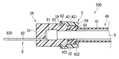
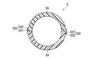
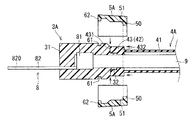
次に図3〜6を参照しつつ、第2実施形態のモールド部付配線部材200について説明する。モールド部付配線部材200は、導体部9と端子8とモールド部3Aと被覆部材4Aと固定部材5とを備える。図3は、モールド部付配線部材200の側方断面図である。図4は、固定部材5の側面図である。図5は、固定部材5の断面図である。図5は、図4のII−II線で切断した断面図である。図6は、モールド部付配線部材200の製造方法の一部を説明する説明図である。図3〜6において、図1,2に示される構成要素と同じ構成要素には、同じ参照符号が付されている。
Second Embodiment
Next, the
本実施形態では、モールド部付配線部材200におけるモールド部3A及び被覆部材4Aが、第1実施形態のモールド部3及び被覆部材4と異なる構成とされている。なお、導体部9及び端子8については、第1実施形態と同様であるため説明を省略する。
In the present embodiment, the
まず、本実施形態におけるモールド部3Aについて説明する。モールド部3Aは、端子8と導体部9との接続部分を覆う部分である。そして、ここでは、図3に示されるように、モールド部3Aの他端部32が、モールド部3Aのうち導体接続部81の周囲を覆う部分から端子8の反対側に突出し、その厚みが比較的薄く形成されている。モールド部3Aの他端部32は、モールド部3Aの他端部32の内周面が導体部9の外周面に接触した状態で、導体部9の周囲を覆っている。また、モールド部3Aの他端部32は、その周囲を後述する被覆部材4Aの端部42によって覆われている。
First, the
また、本実施形態では、モールド部3Aには、係止部61が形成されている。ここでは、係止部61は、モールド部3Aのうち導体接続部81の周囲を覆う比較的大型の部分(即ち、モールド部3Aのうち他端部32以外の部分)の外周面上に形成されている。係止部61は、後述する固定部材5に形成された被係止部62に係止可能な部分である。ここでは、係止部61は、モールド部3Aの外周面上に周方向全体に亘って形成された凹状の凹みである。
In the present embodiment, a locking
次に被覆部材4Aについて説明する。被覆部材4Aは、端部42に形成された弾性変形可能な部分でありモールド部3Aの他端部32の外周面に内周面が密着する弾性環状部43を含む。
Next, the covering
ここでは、弾性環状部43は、自然状態の形状から内径が大きくなるように変形させたときに、自身が有する弾性力によって元の形状に戻ろうとする部分である。即ち、弾性環状部43は、ゴムの性質を示す部分である。第2実施形態では、元の形状に戻ろうとする弾性環状部43の弾性変形によって、被覆部材4Aの端部42(即ち、弾性環状部43)の内周面が、モールド部3Aの他端部32の外周面に密着している。
Here, the elastic
例えば、被覆部材4Aは、端部42でその厚みが分厚くなるように形成されたゴムチューブである場合が考えられる。被覆部材4Aのうち端部42が、中間部41の箇所に比べその厚みが分厚くなるように形成されている場合、端部42(弾性環状部43)の内周面を他端部32の外周面により強く密着させることができる。このような被覆部材4Aは、例えば、金型を用いた一体成型等によって得ることができる。
For example, the case where the covering
本実施形態における弾性環状部43の詳細について説明する。ここでは、弾性環状部43は、上述のように中間部41の箇所よりもその厚みが分厚くなるように形成されている。また、ここでは、弾性環状部43の外径が、中間部41の外径よりも大きくなるように形成されている。そして、弾性環状部43のうち中間部41側の端面(以下、他方側端面432)には、後述する固定部材5の押付面51が接触する。
Details of the elastic
また、ここでは、自然状態の弾性環状部43の内径は、モールド部3Aの他端部32の外径よりも小さくなるように構成されていることが考えられる。この場合、弾性環状部43の内周面がモールド部3Aの他端部32の外周面に強く密着する。
Here, it is considered that the inner diameter of the elastic
なお、本実施形態では、さらに、モールド部3Aの他端部32の他に導体部9の延在方向における一部の外周面にも密着する。即ち、弾性環状部43は、自然状態において弾性環状部43の内径が導体部9の外径よりも小さい部分を含むことが考えられる。この場合、導体部9に対する被覆部材4Aの位置がずれてしまうことをより確実に抑制できる。ちなみに、ここでは、弾性環状部43は、軸方向における全体の部分で、弾性環状部43の内径が導体部9の外径よりも小さい構成とされている。これにより、導体部9の外周面及び導体部9の周囲を覆うモールド部3Aの他端部32の外周面の両方に弾性環状部43の内周面が密着する。
In the present embodiment, in addition to the
なお、他の例として、弾性環状部が、モールド部の他端部の外周面に密着する部分と導体部の外周面に密着する部分とでその内径が異なる構成とされている場合も考えられる。また、さらに他の例として、弾性環状部がモールド部の他端部のみに密着する場合も考えられる。即ち、弾性環状部が、軸方向における全体の部分で自然状態におけるその内径が、導体部の外径よりも大きく、かつ、モールド部の他端部の外径よりも小さくなるように構成されている場合も考えられる。 As another example, the elastic annular portion may be configured such that the inner diameter is different between the portion that is in close contact with the outer peripheral surface of the other end of the mold portion and the portion that is in close contact with the outer peripheral surface of the conductor portion. . As yet another example, a case where the elastic annular portion is in close contact with only the other end portion of the mold portion may be considered. That is, the elastic annular portion is configured so that the inner diameter in the natural state is larger than the outer diameter of the conductor portion and smaller than the outer diameter of the other end portion of the mold portion in the entire axial direction. There are also cases where
次に固定部材5について説明する。固定部材5は、弾性環状部43のうちモールド部3A側を向く面(ここでは、一方側端面431)をモールド部3Aに押し付けるように接触する部分(以下、押付部50)を含む。また、固定部材5には、一方側端面431をモールド部3Aに押し付けた状態で係止部61に係止する被係止部62が形成されている。
Next, the fixing
ここでは、固定部材5は、複数(ここでは、2つ)の固定部材片5Aを含み、複数の固定部材片5Aが合体した状態で弾性環状部43及びモールド部3Aの他端部32側の一部の周囲を覆う環状の部材である。なお、別の例として、固定部材がヒンジで連結された複数の固定部材片を含む場合も考えられる。
Here, the fixing
ここでは、固定部材5には、複数の固定部材片5Aの合体状態を維持する合体維持部500が形成されている。図4,5に示されるように、ここでは、合体維持部500は、係止爪501と係止孔502とを含む。この場合、複数の固定部材片5Aの内周面同士が向き合った状態で相互に近付けられ、その後、係止爪501が係止孔502に収容される。そして、係止孔502に収容された係止爪501が、係止孔502の内縁部に接触し、係りあうことで、2つの固定部材片5Aの合体状態が維持される。
Here, the fixing
本実施形態では、固定部材5は、例えば、弾性環状部43よりも硬い樹脂製の部材であること等が考えられる。弾性環状部43をモールド部3A側に押し付けるためである。
In the present embodiment, for example, the fixing
そして、ここでは、さらに、固定部材5のうち弾性環状部43の周囲を覆う部分の内径が、モールド部3Aの他端部32の周囲を覆う状態の弾性環状部43の外径よりも小さくなるように構成されている。この場合、複数の固定部材片5Aが、複数の固定部材片5A間に弾性環状部43が介在した状態で合体することで、弾性環状部43の径方向に沿って弾性環状部43をモールド部3Aの他端部32側に押し付けることができる。即ち、ここでは、固定部材5によって、弾性環状部43の内周面がモールド部3Aの他端部32の外周面及び導体部9の外周面により密着する。
Here, the inner diameter of the portion of the fixing
そして、固定部材5には、モールド部3Aの外周面上に形成された係止部61に係止可能な被係止部62が形成されている。ここでは、図3,4に示されるように、被係止部62は、固定部材5の軸方向における一方端58側の内周面に形成されている。ここでは、被係止部62は、固定部材5の内周面側において凸状を成し、係止部61内に収容された状態で係止部61に引っ掛かることが可能に形成されている。
And the to-
また、ここでは、図3,4に示されるように、固定部材5の他方端59側には、弾性環状部43の他方側端面432に接触する押付面51が形成された押付部50が形成されている。押付部50は、固定部材5の内周面側において凸状を成す部分である。押付部50の押付面51は、弾性環状部43の一方側端面431がモールド部3Aに接触した状態で、弾性環状部43の他方側端面432をモールド部3A側に向かって押しつける。これにより、弾性環状部43の一方側端面431がモールド部3Aに比較的強く押し付けられ、この間に液体の侵入経路と成り得る隙間が形成されることが抑制される。
Further, as shown in FIGS. 3 and 4, a
ここでは、図6に示されるように、固定部材5が未装着時で、かつ、弾性環状部43の一方側端面431がモールド部3Aに接触した状態のモールド部3A及び被覆部材4Aにおいて、モールド部3Aの一端部31から他端部32に向かう方向(即ち、モールド部3Aの延在方向)におけるモールド部3Aの凹状の係止部61のうち最も一端部31側の部分から弾性環状部43の他方側端面432までの寸法よりも、固定部材5の軸方向における一方端58から押付面51までの寸法が小さくなるように構成されている。この場合、固定部材5が装着されることで、押付部50の押付面51が、弾性環状部43の他方側端面432を比較的強くモールド部3A側に押し付けることが可能である。即ち、弾性環状部43の一方側端面431とモールド部3Aとの間に隙間が形成されることを抑制できる。
Here, as shown in FIG. 6, in the
以下、本実施形態のモールド部付配線部材200を得る方法を説明する。本実施形態では、まず、端子8と導体部9との接続部分を覆うモールド部3Aのモールド成形が行われる。そして、モールド部3Aが形成された後、被覆部材4Aが導体部9及びモールド部3Aの他端部32の周囲を覆うように被せられる。
Hereinafter, a method of obtaining the wiring member with
そして、図6に示されるように、弾性環状部43の一方側端面431がモールド部3Aに接触した状態で、固定部材5が装着される。ここでは、上述のように、固定部材5が未装着時で、かつ、弾性環状部43の一方側端面431がモールド部3Aに接触した状態のモールド部3A及び被覆部材4Aにおいて、モールド部3Aの延在方向におけるモールド部3Aの凹状の係止部61のうち最も一端部31側の部分から弾性環状部43の他方側端面432までの寸法よりも、固定部材5の軸方向における一方端58から押付面51までの寸法が小さくなるように構成されている。このため、ここでは、図6に示されるように、弾性環状部43の他方側端面432をモールド部3A側に押した状態で、弾性環状部43の周囲から複数の固定部材片5Aが近付けられ、固定部材5が装着される。そして、固定部材5の被係止部62とモールド部3Aの係止部61とが係止することで、固定部材5の押付部50の押付面51が弾性環状部43の他方側端面432をモールド部3Aに向かって押しつけた状態が持続する。これにより、弾性環状部43の一方側端面431がモールド部3Aに密着し、この間に液体の侵入経路と成り得る隙間が形成されることが抑制される。
And as FIG. 6 shows, the fixing
本実施形態においても、被覆部材4Aの中間部41と導体部9との間に空隙が形成されているため、導体部9(即ち、モールド部付配線部材200の配線部分)を比較的容易に曲げることができる。従って、このモールド部付配線部材200においては、配線部分の柔軟性に優れる。
Also in the present embodiment, since a gap is formed between the
また、本実施形態では、弾性環状部43の弾性力によって弾性環状部43の内周面がモールド部3Aの他端部32の外周面に密着するため、弾性環状部43の内周面とモールド部3Aの他端部32の外周面との間から液体が侵入することがより確実に抑制される。即ち、モールド部付配線部材200の止水性がより向上する。
Moreover, in this embodiment, since the inner peripheral surface of the elastic
また、本実施形態では、弾性環状部43のうちモールド部3A側を向く面(一方側端面431)がモールド部3Aに押し付けられる。また、弾性環状部43のうちモールド部3A側を向く一方側端面431がモールド部3Aに押し付けられた状態が、係止部61と被係止部62との係止により持続する。従って、この間から液体が侵入することをより確実に抑制できる。即ち、第2実施形態では、接着剤を用いずにモールド部付配線部材200を止水することができる。
Moreover, in this embodiment, the surface (one side end surface 431) which faces the
<第3実施形態>
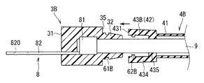
次に図7,8を参照しつつ、第3実施形態のモールド部付配線部材300について説明する。モールド部付配線部材300は、導体部9と端子8とモールド部3Bと被覆部材4Bとを備える。図7は、モールド部付配線部材300の側方断面図である。図8は、モールド部付配線部材300の製造方法の一部を説明する説明図である。図7,8において、図1〜6に示される構成要素と同じ構成要素には、同じ参照符号が付されている。
<Third Embodiment>
Next, the
本実施形態では、モールド部付配線部材300におけるモールド部3B及び被覆部材4Bが、第1,2実施形態のモールド部3,3A及び被覆部材4,4Aと異なる構成とされている。なお、導体部9及び端子8については、第1実施形態及び第2実施形態と同様であるため説明を省略する。
In the present embodiment, the
まず、本実施形態におけるモールド部3Bについて説明する。モールド部3Bは、端子8と導体部9との接続部分を覆う部分である。ここでは、モールド部3Bの他端部32の内周面が導体部9の外周面に接触した状態で、モールド部3Bの他端部32が導体部9の周囲を覆っている。
First, the
ここでは、図7に示されるように、モールド部3Bの他端部32は、モールド部3Bのうち導体接続部81の周囲を覆う部分から端子8の反対側に突出し、その厚みが比較的薄く形成されている。モールド部3Bの他端部32は、その周囲を後述する被覆部材4Bの端部42によって覆われる。また、ここでは、モールド部3Bの他端部32の外周面は、モールド部3Bの一端部31側から他端部32側に向かうにつれ徐々に他端部32の厚みが薄くなるように傾斜する傾斜面を含んでいる。この場合、被覆部材4Bの弾性環状部43Bをモールド部3Bの他端部32に被せる作業をより簡単に行うことができる。
Here, as shown in FIG. 7, the
また、本実施形態では、モールド部3Bには、係止部61Bが形成されている。ここでは、係止部61Bは、モールド部3Bのうち他端部32の外周面上に形成されている。係止部61Bは、後述する弾性環状部43Bに形成された被係止部62Bに係止可能な部分である。ここでは、係止部61Bは、モールド部3Bの外周面上に周方向全体に亘って形成された凹状の凹みである。
Moreover, in this embodiment, the latching | locking
次に被覆部材4Bについて説明する。被覆部材4Bは、端部42に形成された弾性変形可能な部分でありモールド部3Bの他端部32の外周面に内周面が密着する弾性環状部43Bを含む。
Next, the covering
ここでは、弾性環状部43Bは、自然状態の形状から内径が大きくなるように変形させたときに、自身が有する弾性力によって元の形状に戻ろうとする部分である。即ち、弾性環状部43Bは、ゴムの性質を示す部分である。第3実施形態では、元の形状に戻ろうとする弾性環状部43Bの弾性変形によって、被覆部材4Bの端部42(即ち、弾性環状部43B)の内周面が、モールド部3Bの他端部32の外周面に密着している。例えば、被覆部材4Bは、第2実施形態と同様、端部42でその厚みが分厚くなるように形成されたゴムチューブである場合が考えられる。
Here, the elastic
本実施形態における弾性環状部43Bの詳細について説明する。ここでは、弾性環状部43Bは、上述のように中間部41の箇所よりもその厚みが分厚くなるように形成されている。なお、ここでは、弾性環状部43Bの外径が、中間部41の外径よりも大きくなるように形成されている。
Details of the elastic
また、ここでは、図7に示されるように、弾性環状部43Bの内周面は、モールド部3Bの他端部32の他に導体部9の外周面にも密着する。従って、自然状態の弾性環状部43Bの内径は、導体部9の外径よりも小さくなるように構成されていることが考えられる。より具体的には、ここでは、弾性環状部43Bは、自然状態においてモールド部3Bの他端部32の外径よりも小さい部分(第一部分434)と導体部9の外径よりも小さい部分(第二部分435)とを含む。この場合、弾性環状部43Bは、第一部分434でモールド部3Bの他端部32の外周面に密着し、第二部分435で導体部9の外周面に密着する。第一部分434と第二部分435とは、弾性環状部43Bの軸方向において並んで形成されている。この場合、導体部9に対する被覆部材4Bの位置がずれてしまうことをより確実に抑制できる。
Here, as shown in FIG. 7, the inner peripheral surface of the elastic
なお、その他の例として、弾性環状部43Bにおいて第二部分435が省略されている場合、即ち、弾性環状部がモールド部の他端部のみに密着する場合も考えられる。
As another example, a case where the
そして、本実施形態では、弾性環状部43Bには、モールド部3Bの係止部61Bに係止可能な被係止部62Bが形成されている。ここでは、弾性環状部43Bの第一部分434の内周面側に被係止部62Bが形成されている。被係止部62Bは、弾性環状部43Bの内周面側において凸状を成し、係止部61B内に収容された状態で係止部61Bに引っ掛かることが可能に形成されている。
And in this embodiment, the to-
即ち、第3実施形態では、弾性環状部43Bのうちモールド部3B側を向く面(ここでは、一方側端面431)をモールド部3Bに押し付けた状態で係止部61Bに係止する被係止部62Bが、弾性環状部43Bに形成されている。
That is, in the third embodiment, the locked surface that is locked to the locking
また、ここでは、自然状態の弾性環状部43Bの軸方向において一方側端面431から被係止部62Bまでの寸法が、モールド部3Bのうち導体接続部81の周囲を覆う部分の他端部32側の面35から係止部61Bまでの寸法よりも大きくなるように構成されている。このため、係止部61Bと被係止部62Bとが係止した状態で、弾性環状部43Bの一方側端面431がモールド部3Bの面35に強く押し付けられ、この間に隙間が形成されることが抑制される。
Here, the
以下、本実施形態のモールド部付配線部材300を得る方法を説明する。本実施形態では、まず、端子8と導体部9との接続部分を覆うモールド部3Bのモールド成形が行われる。
Hereinafter, a method for obtaining the wiring member with
そして、モールド部3Bが形成された後、被覆部材4Bが導体部9及びモールド部3Bの他端部32の周囲を覆うように被せられる。具体的には、被覆部材4Bが内部に導体部9が挿通された状態で、導体部9の延在方向に沿ってモールド部3B側に移動させられる。
Then, after the
そして、弾性環状部43Bに形成された被係止部62Bを、モールド部3Bの係止部61Bに係止させることで、モールド部3Bと被覆部材4Bとが固定される。このとき、本実施形態では、上述のように、自然状態の弾性環状部43Bの軸方向において一方側端面431から被係止部62Bまでの寸法が、モールド部3Bのうち導体接続部81の周囲を覆う部分の他端部32側の面35から係止部61Bまでの寸法よりも大きくなるように構成されている。そのため、係止部61Bと被係止部62Bとが係止することで、弾性環状部43Bの一方側端面431がモールド部3Bの面35に強く押し付けられる状態が持続する。
And the
また、ここでは、弾性環状部43Bの内周面が、モールド部3Bの他端部32の外周面及び導体部9の外周面に密着する。これにより、導体部9及びモールド部3Bに対する被覆部材4Bの位置ずれてしまうことを抑制できる。
Here, the inner peripheral surface of the elastic
本実施形態においても、被覆部材4Bの中間部41と導体部9との間に空隙が形成されているため、導体部9(即ち、モールド部付配線部材300の配線部分)を比較的容易に曲げることができる。従って、このモールド部付配線部材300においては、配線部分の柔軟性に優れる。
Also in this embodiment, since a gap is formed between the
また、本実施形態では、弾性環状部43Bのうちモールド部3B側を向く一方側端面431がモールド部3Bに押し付けられ、この間に隙間が形成されることが抑制される。また、弾性環状部43Bのうちモールド部3B側を向く一方側端面431がモールド部3Bに押し付けられた状態が、係止部61Bと被係止部62Bとの係止により持続する。その結果、一方側端面431とモールド部3Bとの間から液体が侵入することをより確実に抑制できる。即ち、第3実施形態では、接着剤を用いずにモールド部付配線部材300を止水することができる。
Moreover, in this embodiment, the one
また、第3実施形態では、モールド部付配線部材300を構成する部品点数の増大を抑制できる。
Moreover, in 3rd Embodiment, the increase in the number of parts which comprises the
<応用例>
係止部がモールド部の外周面上で凸状に形成され、被係止部が固定部材の内周面側で又は弾性環状部の内周面側で凹状に形成された構成であってもよい。
<Application example>
Even if the locking portion is formed in a convex shape on the outer peripheral surface of the mold portion, and the locked portion is formed in a concave shape on the inner peripheral surface side of the fixing member or on the inner peripheral surface side of the elastic annular portion Good.
第1実施形態において、被覆部材が熱収縮チューブ以外の部材により形成される場合も考えられる。例えば、被覆部材が、導体部の外径よりも内径が大きいゴムチューブの端部を導体部の外周面に接着することで得られる場合等も考えられる。 In 1st Embodiment, the case where a coating | coated member is formed with members other than a heat contraction tube is also considered. For example, a case where the covering member is obtained by bonding the end of a rubber tube having an inner diameter larger than the outer diameter of the conductor portion to the outer peripheral surface of the conductor portion is also conceivable.
第2実施形態において、固定部材が省略された構成であってもよい。即ち、被覆部材の弾性環状部の弾性力のみで、弾性環状部がモールド部の他端部の外周面に密着して覆う場合も考えられる。 In the second embodiment, the fixing member may be omitted. That is, the elastic annular portion may be in close contact with the outer peripheral surface of the other end portion of the mold portion by only the elastic force of the elastic annular portion of the covering member.
なお、本発明に係るモールド部付配線部材は、各請求項に記載された発明の範囲において、以上に示された各実施形態及び応用例を自由に組み合わせること、或いは、各実施形態及び応用例を適宜、変形する又は一部を省略することによって構成されることも可能である。 In addition, the wiring member with a mold part according to the present invention can be freely combined with each of the embodiments and application examples shown above within the scope of the invention described in each claim, or each embodiment and application example. It is also possible to configure by appropriately modifying or omitting a part.
1 第一接着剤
100 モールド部付配線部材
2 第二接着剤
200 モールド部付配線部材
3 モールド部
300 モールド部付配線部材
31 一端部
32 他端部
3A モールド部
3B モールド部
4 被覆部材
41 中間部
42 端部
43 弾性環状部
4A 被覆部材
4B 被覆部材
5 固定部材
50 押付部
61 係止部
62 被係止部
8 端子
9 導体部
DESCRIPTION OF SYMBOLS 1 1st
Claims (7)
前記導体部の端部に接続された端子と、
一端部側から前記端子が突出し、かつ、他端部側から前記導体部が延出するように前記導体部と前記端子との接続部分を覆うモールド部と、
中間部で前記導体部との間に空隙が形成された状態で前記導体部の周囲を覆い、端部で前記モールド部の前記他端部と密着する被覆部材と、を備える、モールド部付配線部材。 A linear conductor,
A terminal connected to an end of the conductor portion;
A mold part that covers the connection part between the conductor part and the terminal so that the terminal protrudes from one end part side, and the conductor part extends from the other end part side,
A wiring with a mold part, comprising: a covering member that covers the periphery of the conductor part in a state where a gap is formed between the conductor part and an intermediate part, and that is in close contact with the other end part of the mold part at an end part Element.
前記被覆部材の前記端部の外周面と前記モールド部の前記他端部の内周面とが密着している、モールド部付配線部材。 It is a wiring member with a mold part according to claim 1,
A wiring member with a mold part, wherein an outer peripheral surface of the end part of the covering member is in close contact with an inner peripheral surface of the other end part of the mold part.
前記被覆部材の前記端部の外周面と前記モールド部の前記他端部の内周面との間に設けられ、前記被覆部材の前記端部の外周面と前記モールド部の前記他端部の内周面とを密着させる第一接着剤をさらに備える、モールド部付配線部材。 It is a wiring member with a mold part according to claim 2,
Provided between the outer peripheral surface of the end portion of the covering member and the inner peripheral surface of the other end portion of the mold portion, and between the outer peripheral surface of the end portion of the covering member and the other end portion of the mold portion. The wiring member with a mold part further provided with the 1st adhesive agent which closely_contact | adheres to an internal peripheral surface.
前記被覆部材の前記端部の内周面と前記導体部の外周面との間に設けられ、前記被覆部材の前記端部の内周面を前記導体部の外周面に密着させる第二接着剤をさらに備える、モールド部付配線部材。 It is a wiring member with a mold part according to any one of claims 1 to 3,
A second adhesive provided between the inner peripheral surface of the end portion of the covering member and the outer peripheral surface of the conductor portion, and tightly contacts the inner peripheral surface of the end portion of the covering member with the outer peripheral surface of the conductor portion. A wiring member with a mold part, further comprising:
前記被覆部材は、前記端部に形成された弾性変形可能な部分であり前記モールド部の前記他端部の外周面に内周面が密着する弾性環状部を含む、モールド部付配線部材。 It is a wiring member with a mold part according to claim 1,
The said covering member is an elastically deformable part formed in the said edge part, and is a wiring member with a mold part containing the elastic annular part which an inner peripheral surface closely_contact | adheres to the outer peripheral surface of the said other end part of the said mold part.
前記モールド部には、係止部が形成され、
前記弾性環状部のうち前記モールド部側を向く面を前記モールド部に押し付けるように接触する部分を含み、前記弾性環状部のうち前記モールド部側を向く面を前記モールド部に押し付けた状態で前記係止部に係止する被係止部が形成された固定部材をさらに備える、モールド部付配線部材。 It is a wiring member with a mold part according to claim 5,
The mold part is formed with a locking part,
The elastic annular portion includes a portion that comes into contact with the mold portion so that the surface facing the mold portion side is pressed against the mold portion, and the surface facing the mold portion side of the elastic annular portion is pressed against the mold portion. A wiring member with a mold part, further comprising a fixing member in which a locked part to be locked to the locking part is formed.
前記モールド部には、係止部が形成され、
前記弾性環状部のうち前記モールド部側を向く面を前記モールド部に押し付けた状態で前記係止部に係止する被係止部が、前記弾性環状部に形成されている、モールド部付配線部材。 It is a wiring member with a mold part according to claim 5,
The mold part is formed with a locking part,
A wire with a mold part, wherein a locked part that is locked to the locking part in a state where a surface facing the mold part side of the elastic annular part is pressed against the mold part is formed in the elastic annular part. Element.
Priority Applications (4)
| Application Number | Priority Date | Filing Date | Title |
|---|---|---|---|
| JP2015226525A JP6497302B2 (en) | 2015-11-19 | 2015-11-19 | Wiring member with mold part |
| PCT/JP2016/082741 WO2017086182A1 (en) | 2015-11-19 | 2016-11-04 | Wiring member having molded part |
| US15/773,608 US10348002B2 (en) | 2015-11-19 | 2016-11-04 | Wiring member having molded part |
| CN201680065285.4A CN108352631B (en) | 2015-11-19 | 2016-11-04 | Wiring member with molding part |
Applications Claiming Priority (1)
| Application Number | Priority Date | Filing Date | Title |
|---|---|---|---|
| JP2015226525A JP6497302B2 (en) | 2015-11-19 | 2015-11-19 | Wiring member with mold part |
Publications (3)
| Publication Number | Publication Date |
|---|---|
| JP2017097990A JP2017097990A (en) | 2017-06-01 |
| JP2017097990A5 JP2017097990A5 (en) | 2018-05-10 |
| JP6497302B2 true JP6497302B2 (en) | 2019-04-10 |
Family
ID=58718021
Family Applications (1)
| Application Number | Title | Priority Date | Filing Date |
|---|---|---|---|
| JP2015226525A Active JP6497302B2 (en) | 2015-11-19 | 2015-11-19 | Wiring member with mold part |
Country Status (4)
| Country | Link |
|---|---|
| US (1) | US10348002B2 (en) |
| JP (1) | JP6497302B2 (en) |
| CN (1) | CN108352631B (en) |
| WO (1) | WO2017086182A1 (en) |
Families Citing this family (4)
| Publication number | Priority date | Publication date | Assignee | Title |
|---|---|---|---|---|
| CN110678507B (en) | 2017-05-17 | 2022-07-12 | 株式会社新菱 | Method, apparatus and product for producing regenerated carbon fiber bundle, and method for producing regenerated carbon fiber, pulverized product and reinforced resin |
| JP6832446B2 (en) * | 2018-06-01 | 2021-02-24 | 東芝三菱電機産業システム株式会社 | Insulation cover |
| JP7084341B2 (en) * | 2019-03-06 | 2022-06-14 | トヨタ自動車株式会社 | Molding method of connector part |
| JP2020162274A (en) * | 2019-03-26 | 2020-10-01 | 株式会社オートネットワーク技術研究所 | Wire Harness |
Family Cites Families (15)
| Publication number | Priority date | Publication date | Assignee | Title |
|---|---|---|---|---|
| US6666732B1 (en) * | 2001-05-21 | 2003-12-23 | John E. Endacott | Terminal connector |
| JP2005005177A (en) * | 2003-06-13 | 2005-01-06 | Yazaki Corp | Waterproof device between cable and housing |
| US7348489B2 (en) * | 2004-09-15 | 2008-03-25 | Fci Americas Technology, Inc. | Electrical connector for aluminum conductor composite core (ACCC) cable |
| US7344396B2 (en) * | 2005-08-23 | 2008-03-18 | Utilx Corporation | Cable connection assembly |
| JP5029505B2 (en) * | 2008-06-16 | 2012-09-19 | 住友電装株式会社 | Waterproof structure of connector connection |
| ES2373078T3 (en) * | 2009-03-02 | 2012-01-31 | Tyco Electronics Uk Ltd. | TERMINATION OF SCREEN BRAKE FOR DISPLAYED ELECTRICAL CONNECTOR. |
| JP5500384B2 (en) * | 2010-11-05 | 2014-05-21 | 株式会社オートネットワーク技術研究所 | Electric wire with terminal fitting and method of manufacturing electric wire with terminal fitting |
| JP5884134B2 (en) * | 2011-11-25 | 2016-03-15 | 矢崎総業株式会社 | Manufacturing method of wire harness |
| JP5712911B2 (en) * | 2011-12-08 | 2015-05-07 | 株式会社オートネットワーク技術研究所 | Electric wire with terminal and manufacturing method thereof |
| JP5708532B2 (en) | 2012-03-08 | 2015-04-30 | 株式会社オートネットワーク技術研究所 | Electric wire with terminal |
| JP2014146538A (en) * | 2013-01-30 | 2014-08-14 | Yazaki Corp | Terminal waterproof structure |
| DE202013006413U1 (en) * | 2013-07-17 | 2014-10-22 | Leoni Bordnetz-Systeme Gmbh | Device for electrically contacting a shielding of an electrical cable to a housing and prefabricated electrical cable |
| JP6142807B2 (en) * | 2014-01-17 | 2017-06-07 | 株式会社オートネットワーク技術研究所 | Wire Harness |
| JP2015135793A (en) * | 2014-01-20 | 2015-07-27 | 日立金属株式会社 | Sealing structure of cable lead-out part, cable with sensor, and cable with terminal fitting |
| JP6164257B2 (en) * | 2015-07-10 | 2017-07-19 | 株式会社オートネットワーク技術研究所 | Electric wire with mold part and method of manufacturing electric wire with mold part |
-
2015
- 2015-11-19 JP JP2015226525A patent/JP6497302B2/en active Active
-
2016
- 2016-11-04 WO PCT/JP2016/082741 patent/WO2017086182A1/en active Application Filing
- 2016-11-04 CN CN201680065285.4A patent/CN108352631B/en active Active
- 2016-11-04 US US15/773,608 patent/US10348002B2/en active Active
Also Published As
| Publication number | Publication date |
|---|---|
| US20190081418A1 (en) | 2019-03-14 |
| CN108352631A (en) | 2018-07-31 |
| US10348002B2 (en) | 2019-07-09 |
| WO2017086182A1 (en) | 2017-05-26 |
| JP2017097990A (en) | 2017-06-01 |
| CN108352631B (en) | 2020-03-27 |
Similar Documents
| Publication | Publication Date | Title |
|---|---|---|
| JP6164257B2 (en) | Electric wire with mold part and method of manufacturing electric wire with mold part | |
| JP6497302B2 (en) | Wiring member with mold part | |
| US10355373B2 (en) | Crimp terminal and wire with crimp terminal | |
| JP6142807B2 (en) | Wire Harness | |
| US10096986B2 (en) | Device for sealing an electrical connection | |
| JP5742704B2 (en) | Electric wire with terminal | |
| JP6323317B2 (en) | Electric wire with terminal | |
| JP5962589B2 (en) | Electric wire with terminal | |
| JP2016110901A (en) | Connection terminal structure for wiring harness | |
| US10476182B2 (en) | Molded portion-equipped electrical wire | |
| JP2017139151A (en) | Wire with heat-shrinkable tubing | |
| WO2018003499A1 (en) | Electromagnetic shield component and electromagnetic shield component-equipped electric wire | |
| JP6245145B2 (en) | Electric wire with mold part and method of manufacturing electric wire with mold part | |
| JP2014229586A (en) | Wiring harness | |
| JP6112022B2 (en) | Wire with mold | |
| JP6417738B2 (en) | Wire Harness | |
| JP5907119B2 (en) | Wire harness manufacturing method and wire harness | |
| JP6135520B2 (en) | Wire Harness | |
| JP2023127199A (en) | Wiring harness | |
| JP2014229572A (en) | Wire with terminal | |
| JP2015076242A (en) | Wire with terminal | |
| JP2017201603A (en) | Wiring module | |
| JP2013229165A (en) | Waterproof structure of electric wire connecting portion |
Legal Events
| Date | Code | Title | Description |
|---|---|---|---|
| A621 | Written request for application examination |
Free format text: JAPANESE INTERMEDIATE CODE: A621 Effective date: 20180226 |
|
| A521 | Request for written amendment filed |
Free format text: JAPANESE INTERMEDIATE CODE: A523 Effective date: 20180326 |
|
| TRDD | Decision of grant or rejection written | ||
| A01 | Written decision to grant a patent or to grant a registration (utility model) |
Free format text: JAPANESE INTERMEDIATE CODE: A01 Effective date: 20190212 |
|
| A61 | First payment of annual fees (during grant procedure) |
Free format text: JAPANESE INTERMEDIATE CODE: A61 Effective date: 20190225 |
|
| R150 | Certificate of patent or registration of utility model |
Ref document number: 6497302 Country of ref document: JP Free format text: JAPANESE INTERMEDIATE CODE: R150 |