JP2014229572A - Wire with terminal - Google Patents
Wire with terminal Download PDFInfo
- Publication number
- JP2014229572A JP2014229572A JP2013110546A JP2013110546A JP2014229572A JP 2014229572 A JP2014229572 A JP 2014229572A JP 2013110546 A JP2013110546 A JP 2013110546A JP 2013110546 A JP2013110546 A JP 2013110546A JP 2014229572 A JP2014229572 A JP 2014229572A
- Authority
- JP
- Japan
- Prior art keywords
- water stop
- terminal
- wire
- tube
- intermediate portion
- Prior art date
- Legal status (The legal status is an assumption and is not a legal conclusion. Google has not performed a legal analysis and makes no representation as to the accuracy of the status listed.)
- Pending
Links
Images


Abstract
Description
本発明は、絶縁電線と端子金具とを含む端子付電線に関する。 The present invention relates to an electric wire with a terminal including an insulated wire and a terminal fitting.
一般に、自動車などの車両に搭載されるワイヤハーネスは、絶縁電線とその端部に接続された端子金具とを含む端子付電線を備えている。 Generally, the wire harness mounted in vehicles, such as a motor vehicle, is equipped with the electric wire with a terminal containing the insulated wire and the terminal metal fitting connected to the edge part.
端子付電線において、絶縁電線の芯線がアルミニウム線である場合、芯線と圧着端子との接触部が異種金属接触腐食によって腐食しやすい。端子付電線における異種金属接触腐食を防止するためには、絶縁電線の芯線と圧着端子とが接触する部分への液体の浸入を防ぐことが有効である。 In the electric wire with terminal, when the core wire of the insulated wire is an aluminum wire, the contact portion between the core wire and the crimp terminal is likely to be corroded by different metal contact corrosion. In order to prevent different metal contact corrosion in the electric wire with terminal, it is effective to prevent liquid from entering the portion where the core wire of the insulated wire and the crimp terminal are in contact.
例えば、特許文献1に示される端子付電線は、絶縁電線と圧着端子と絶縁電線の芯線への液体の浸入を防ぐ熱収縮タイプの止水チューブとを備える。熱収縮タイプの止水チューブは、熱収縮チューブとその内側面に形成された熱可塑性接着剤の層とを含む2層構造を有している。
For example, a terminal-attached electric wire disclosed in
特許文献1に示される端子付電線において、熱収縮タイプの止水チューブは、絶縁電線におけるインシュレーションバレルが圧着された部分から芯線の先端に亘る領域を圧着端子の外側から覆う。
In the electric wire with a terminal shown in
ところで、端子金具は、芯線の端部が接続される芯線接続部と接続相手に直接接続される接点部との間の板状の中間部を有している。熱収縮タイプの止水チューブは、端子付電線における絶縁電線の絶縁被覆の部分から端子金具の中間部までに亘る領域を覆う。 By the way, the terminal fitting has a plate-shaped intermediate portion between the core wire connecting portion to which the end portion of the core wire is connected and the contact portion directly connected to the connection partner. The heat-shrinkable water stop tube covers a region extending from the insulation coating portion of the insulated wire to the intermediate portion of the terminal fitting in the terminal-attached electric wire.
熱収縮タイプの止水チューブが端子金具を備える端子付電線で用いられた場合、端子金具における板状の中間部の表面と止水チューブの内側面との間に隙間が形成されてしまう場合がある。特に、中間部が幅の広い平板状である場合に隙間が形成されやすい。その隙間は、芯線の部分への液体の浸入経路となる。 When a heat-shrinkable water stop tube is used in a terminal-equipped electric wire with a terminal fitting, a gap may be formed between the surface of the plate-shaped intermediate portion of the terminal fitting and the inner surface of the water stop tube. is there. In particular, a gap is easily formed when the intermediate portion is a wide flat plate. The gap serves as a liquid intrusion path into the core wire portion.
また、中間部の表面と止水チューブの内側面との間に隙間が生じないほどに止水チューブにおける熱可塑性接着剤の量を増やすと、端子付電線における止水チューブの部分、特に、止水チューブにおける絶縁被覆を覆う部分が太くなり過ぎる。 In addition, if the amount of the thermoplastic adhesive in the water stop tube is increased so that there is no gap between the surface of the intermediate portion and the inner surface of the water stop tube, the portion of the water stop tube in the electric wire with terminal, The portion of the water tube that covers the insulation coating becomes too thick.
また、止水チューブを加熱する時間が長過ぎると、止水チューブの最外層が過加熱によってダメージを受ける恐れがある。そのため、仮に止水チューブの接着剤が増量されても、上記のダメージが生じない程度の加熱時間内に、接着剤の全量を止水チューブと端子金具との間の全域に充満させることができない事態も生じ得る。 Moreover, if the time for heating the water stop tube is too long, the outermost layer of the water stop tube may be damaged by overheating. For this reason, even if the adhesive amount of the water stop tube is increased, the entire amount of the adhesive cannot be filled in the entire area between the water stop tube and the terminal fitting within the heating time that does not cause the above damage. Things can happen.
本発明の目的は、端子付電線において、止水チューブの部分が過剰に太くならないようにしつつ端子金具と止水チューブとの間に隙間が形成されることを確実に防ぎ、芯線の腐食を防止することである。 The object of the present invention is to reliably prevent the formation of a gap between the terminal fitting and the water stop tube while preventing the water stop tube portion from becoming excessively thick in the electric wire with terminal, and to prevent corrosion of the core wire. It is to be.
第1態様に係る端子付電線は、絶縁電線と端子金具と止水チューブとを備える。上記端子金具は、上記絶縁電線の芯線の端部が接続された芯線接続部とその芯線接続部に連なる板状の中間部とその中間部に連なり接続相手に直接接続される接点部とを有する。上記止水チューブは、熱収縮チューブとその熱収縮チューブの内側面に形成された熱可塑性の接着剤の層とを含む2層構造を有する。上記止水チューブは、熱を受けて収縮した状態で、上記絶縁電線及び上記端子金具における止水領域に密着してその止水領域を覆う。上記止水領域は、上記絶縁電線及び上記端子金具における上記絶縁電線の絶縁被覆の部分から上記中間部までに亘る領域である。上記止水チューブに、上記接着剤の層が軟化した状態で上記端子金具の上記中間部に押し付けられた跡であるプレス跡が上記中間部を横断して形成されている。 The electric wire with a terminal concerning the 1st mode is provided with an insulated electric wire, a terminal metal fitting, and a water stop tube. The terminal fitting has a core wire connecting portion to which an end portion of the core wire of the insulated wire is connected, a plate-like intermediate portion connected to the core wire connecting portion, and a contact portion connected to the intermediate portion and directly connected to the connection partner. . The water blocking tube has a two-layer structure including a heat shrinkable tube and a thermoplastic adhesive layer formed on the inner surface of the heat shrinkable tube. In the state which received the heat and shrink | contracted, the said water stop tube closely_contact | adheres to the water stop area | region in the said insulated wire and the said terminal metal fitting, and covers the water stop area | region. The said water stop area | region is an area | region ranging from the part of the insulation coating of the said insulated wire in the said insulated wire and the said terminal metal fitting to the said intermediate part. A press mark, which is a mark pressed against the intermediate part of the terminal fitting in a state where the adhesive layer is softened, is formed across the intermediate part in the water stop tube.
第2態様に係る端子付電線は、第1態様に係る端子付電線の一態様である。第2態様に係る端子付電線において、上記止水チューブの上記プレス跡は、上記中間部の全周方向に亘って環状に形成されている。 The electric wire with a terminal concerning the 2nd mode is one mode of the electric wire with a terminal concerning the 1st mode. The electric wire with a terminal concerning the 2nd mode WHEREIN: The said press trace of the said water stop tube is formed cyclically | annularly over the perimeter direction of the said intermediate part.
第3態様に係る端子付電線は、第1態様又は第2態様に係る端子付電線の一態様である。第3態様に係る端子付電線において、上記絶縁電線の上記芯線はアルミニウムを主成分とする部材であり、上記端子金具は銅を主成分とする部材である。 The electric wire with a terminal concerning the 3rd mode is one mode of the electric wire with a terminal concerning the 1st mode or the 2nd mode. The electric wire with a terminal concerning the 3rd mode WHEREIN: The said core wire of the said insulated wire is a member which has aluminum as a main component, and the said terminal metal fitting is a member which has copper as a main component.
上記の各態様において、熱収縮タイプの止水チューブは、止水領域に位置する絶縁電線及び端子金具に密着している。また、止水チューブには、端子金具の板状の中間部、即ち、接点部と芯線接続部との間の部分を横断するプレス跡が形成されている。そのプレス跡は、止水チューブの接着剤の層が軟化した状態で止水チューブが中間部に押し付けられた跡である。 In each of the above aspects, the heat-shrinkable water stop tube is in close contact with the insulated wire and the terminal fitting located in the water stop region. The water stop tube is formed with a press mark traversing the plate-shaped intermediate portion of the terminal fitting, that is, the portion between the contact portion and the core wire connecting portion. The press mark is a mark that the water stop tube is pressed against the intermediate portion in a state where the adhesive layer of the water stop tube is softened.
前述したように、熱収縮タイプの止水チューブは、単に加熱されただけでは板状の中間部との間に隙間が生じやすい。しかしながら、止水チューブが接着剤の層が軟化した状態で板状の中間部に押し付けられると、外側の熱収縮チューブが内側の接着剤の層によって板状の中間部に対して隙間無く接着された状態となる。その結果、端子金具と止水チューブとの間に隙間が形成されることを回避でき、ひいては芯線の腐食を防止できる。 As described above, the heat-shrinkable water-stopping tube is likely to have a gap with the plate-shaped intermediate portion simply by being heated. However, when the water stop tube is pressed against the plate-shaped intermediate portion with the adhesive layer softened, the outer heat shrinkable tube is bonded to the plate-shaped intermediate portion without gaps by the inner adhesive layer. It becomes a state. As a result, it is possible to avoid the formation of a gap between the terminal fitting and the water stop tube, thereby preventing the core wire from being corroded.
また、大量の熱可塑性接着剤が熱収縮チューブの内側面に形成される必要がなく、止水チューブにおける絶縁電線の絶縁被覆を覆う部分が過剰に太くなることもない。 Further, it is not necessary to form a large amount of thermoplastic adhesive on the inner surface of the heat shrinkable tube, and the portion of the water stop tube that covers the insulating coating of the insulated wire does not become excessively thick.
また、第2態様においては、止水チューブのプレス跡が端子金具の中間部の全周方向に亘って環状に形成されている。止水チューブと板状の中間部との間の隙間は、中間部の両主面において生じやすい。そうであっても、プレス跡が中間部の両主面及び両側面に亘って環状に形成されていれば、止水チューブと中間部との間に隙間が形成されることをより確実に防止できる。 Moreover, in the 2nd aspect, the press trace of the water stop tube is formed cyclically | annularly over the perimeter direction of the intermediate part of a terminal metal fitting. A gap between the water stop tube and the plate-shaped intermediate portion is likely to occur on both main surfaces of the intermediate portion. Even so, if the press mark is formed in an annular shape over both the main surface and both side surfaces of the intermediate portion, it is more reliably prevented that a gap is formed between the water stop tube and the intermediate portion. it can.
また、第3態様においては、絶縁電線の芯線と端子金具とが異なる種類の金属材料で構成されている。この構成は、液体が絶縁電線の芯線の部分へ浸入した場合に、異種金属接触腐食が特に生じやすい構成である。そのため、絶縁電線の芯線の部分への液体の浸入を防止できる効果がより顕著となる。 Moreover, in the 3rd aspect, the core wire and terminal metal fitting of an insulated wire are comprised with the kind of different metal material. This configuration is a configuration in which dissimilar metal contact corrosion is particularly likely to occur when the liquid enters the core wire portion of the insulated wire. Therefore, the effect which can prevent the penetration | invasion of the liquid to the part of the core wire of an insulated wire becomes more remarkable.
以下、添付の図面を参照しながら、実施形態について説明する。以下の実施形態は、本発明を具体化した一例であり、本発明の技術的範囲を限定する事例ではない。各実施形態における端子付電線は、自動車などの車両に搭載される。 Hereinafter, embodiments will be described with reference to the accompanying drawings. The following embodiment is an example embodying the present invention, and is not an example of limiting the technical scope of the present invention. The electric wire with terminal in each embodiment is mounted on a vehicle such as an automobile.
<第1実施形態>
まず、図1〜3を参照しつつ、第1実施形態に係る端子付電線1の構成について説明する。端子付電線1は、絶縁電線9と、その端部に取り付けられた端子金具8と、絶縁電線9の端部を覆う熱収縮タイプの止水チューブ3とを備える。
<First Embodiment>
First, the configuration of the terminal-attached
<絶縁電線>
絶縁電線9は、長尺な導体である芯線91と、その芯線91の周囲を覆う絶縁体である絶縁被覆92とを有する。通常、芯線91は、複数の細い素線が撚り合わされた撚り線であるが、芯線91が単線であることも考えられる。
<Insulated wire>
The insulated
端子金具8が取り付けられる絶縁電線9の端部は、予め一定の長さの分の芯線91の周囲から絶縁被覆92が剥がれた状態、即ち、一定の長さ分の芯線91の端部が絶縁被覆92の端から延び出た状態に加工されている。
The end portion of the insulated
端子付電線1において、絶縁電線9の芯線は、例えば、銅又はアルミニウムを主成分とする金属の線材である。
In the terminal-attached
<端子金具>
端子金具8は絶縁電線9の端部に接続されている。端子金具8は、少なくとも接点部81、中間部82及び芯線接続部83を有している。本実施形態における端子金具8は、さらに被覆圧着部84を有している。
<Terminal fitting>
The
被覆圧着部84は、絶縁電線9の絶縁被覆92の部分の端部に圧着される部分である。芯線接続部83は、絶縁電線9の芯線91の端部が接続された部分である。例えば、芯線91の端部は、超音波溶接などの溶接によって芯線接続部83に接続されている。
The
中間部82は、芯線接続部83と接点部81とに連なる板状の部分である。本実施形態における中間部82は平板状である。以下の説明において、中間部82における芯線91が位置する側の主面のことを第一主面、その反対側の主面のことを第二主面と称する。
The
接点部81は、接続相手に直接接続される部分である。接点部81は、芯線接続部83に対し反対側において中間部82に連なっている。本実施形態における接点部81は、平板状の部分である。例えば、接続相手への固定用のネジが通される孔811が、平板状の接点部81に形成されている。
The
端子付電線1において、絶縁電線9の芯線91と端子金具8とがそれぞれ異種の金属で構成されていることが考えられる。例えば、芯線91が、アルミニウム線、即ち、アルミニウムを主成分とする金属(アルミニウムまたはアルミニウム合金)の線材であることが考えられる。一方、端子金具8が、銅もしくは黄銅などの銅合金の基材に、錫(Sn)もしくは錫に銀(Ag)、銅(Cu)、ビスマス(Bi)などが添加された錫合金のメッキが施された部材であることが考えられる。この場合、端子金具8と接触する芯線91は、電解液となる液体が浸入すると腐食しやすい。
In the electric wire with
<止水チューブ>
端子付電線1は、芯線91の腐食を防ぐために液体の浸入を防ぐ止水構造を備えている。端子付電線1における止水構造は止水チューブ3を含む。
<Water stop tube>
The terminal-attached
止水チューブ3は、熱を受けて収縮する熱収縮タイプのチューブである。図2は、収縮前の止水チューブ3を示し、図1は収縮後の止水チューブ3を示している。
The
止水チューブ3は、熱収縮チューブ31とその熱収縮チューブ31の内側面に形成された熱可塑性の接着剤層32とを含む2層構造を有する。
The
なお、熱収縮チューブ31は、例えば、ポリオレフィン系樹脂もしくはナイロン系樹脂などの合成樹脂からなる筒状の部材である。熱収縮チューブ31は、押し出し成形によりごく細い筒状に成形された樹脂部材が、加熱された状態で太い筒状へ引き伸ばされた後に冷却されることによって得られる。このようにして得られた熱収縮チューブ31は、加熱された場合、引き伸ばされる前の細い筒状まで収縮する形状記憶特性を有する。
The heat shrinkable
止水チューブ3は、熱を受けて収縮した状態で、絶縁電線9及び端子金具8における止水領域に密着してその止水領域を覆う。止水領域は、絶縁電線9及び端子金具8における絶縁被覆92の部分から中間部82までに亘る領域である。
The water-
さらに、止水チューブ3における端子金具8の中間部82を覆う部分には、プレス跡33が中間部82を横断して形成されている。プレス跡33は、接着剤層32が軟化した状態の止水チューブ3が端子金具8の中間部82に押し付けられた跡である。プレス跡33は、少なくとも中間部82の第一主面及び第二主面の各々を横断して形成されている。
Further, a
従って、熱収縮チューブ31の第1の端部は、絶縁電線9における絶縁被覆92の部分の外周面に対しその全周方向に亘って接着剤層32によって隙間無く接着されている。なお、熱収縮チューブ31の第1の端部は、接点部81側に対して反対側の端部であり、熱収縮チューブ31の第2の端部は、接点部81側の端部である。
Therefore, the first end portion of the
さらに、プレス跡33の位置において、熱収縮チューブ31は、端子金具8の中間部82の表面に対しその全周方向に亘って接着剤層32によって隙間無く接着されている。より具体的には、熱収縮チューブ31は、プレス跡33の位置において、板状の中間部82の第一主面、第二主面及び両側面に対して接着剤層32によって接着されている。
Further, at the position of the
即ち、止水チューブ3は、絶縁電線9の芯線91の端部及び端子金具8における芯線91に接触する部分を密封している。なお、密封性を高めるために、止水チューブ3のプレス跡33は、中間部82の全周方向に亘って環状に形成されていることが望ましい。この場合、プレス跡33は、中間部82の第一主面、第二主面及び両側面の各々を横断して形成されている。
That is, the
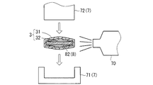
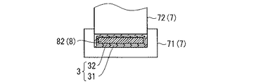
続いて、図3〜5を参照しつつ、止水チューブ3のプレス跡33を形成する方法の一例について説明する。図3はプレス跡33を形成する前の加熱工程における端子付電線1の断面図である。図4はプレス跡33を形成するプレス工程における端子付電線1の断面図である。図5はプレス跡33が形成された端子付電線1の断面図である。
Then, an example of the method of forming the
図3に示されるように、熱収縮タイプの止水チューブ3は、単に加熱されただけでは板状の中間部82との間に隙間が生じやすい。そこで、止水チューブ3を端子金具8の中間部82に押し付けることにより、止水チューブ3と中間部82との間の隙間を無くす。
As shown in FIG. 3, the heat-shrinkable water-stopping
図3が示すように、止水チューブ3を端子金具8に押し付ける工程の準備として、止水チューブ3における端子金具8の中間部82を覆う部分を加熱する加熱工程が実行される。図3が示す例では、止水チューブ3は熱風送風機70によって加熱されている。この加熱工程において、止水チューブ3は、接着剤層32が中間部82に対して粘着可能な程度に軟化するまで加熱される。なお、止水チューブ3を収縮させるために止水チューブ3全体を加熱する工程が、押し付け工程のための加熱工程を兼ねてもよい。
As shown in FIG. 3, as a preparation for the step of pressing the
続いて、図3,4に示されるように、接着剤層32が軟化した状態の止水チューブ3を端子金具8の中間部82に押し付けるプレス工程が実行される。例えば、プレス工程は、止水チューブ3における端子金具8の中間部82を覆う部分を一対のプレス部材7で挟み込む工程である。
Subsequently, as shown in FIGS. 3 and 4, a pressing process is performed in which the
図3,4に示される例では、一対のプレス部材7は、第一金属部材71と第二金属部材72とを含む。第一金属部材71は、止水チューブ3を端子金具8の中間部82の一方の主面及び両側面に押し付ける。第二金属部材72、止水チューブ3を中間部82の他方の主面に押し付ける。
In the example shown in FIGS. 3 and 4, the pair of
また、一対のプレス部材7は、端子金具8の中間部82に押し付けられた止水チューブ3を冷却する機能も果たす。止水チューブ3の熱は、熱伝導性の高い第一金属部材71と第二金属部材72を通じて放熱される。その結果、図5が示すように、接着剤層32が中間部82に固着し、止水チューブ3における一対のプレス部材7が接触した部分にプレス跡33が形成される。
The pair of
<第2実施形態>
次に、図6を参照しつつ、第2実施形態に係る端子付電線1Aについて説明する。この端子付電線1Aは、図1,2に示された端子付電線1と比較して、複数の絶縁電線9を備えている点が異なる。図6において、図1〜5に示される構成要素と同じ構成要素は、同じ参照符号が付されている。以下、端子付電線1Aにおける端子付電線1と異なる点についてのみ説明する。なお、図6は端子付電線1Aの平面図である。
Second Embodiment
Next, an electric wire with terminal 1A according to the second embodiment will be described with reference to FIG. 1 A of this electric wire with a terminal differs in the point provided with the some
端子付電線1Aは、電線束90、端子金具8A、被覆間止水部材2及び止水チューブ3を備える。電線束90は、芯線91どうしが接合された複数の絶縁電線9を含む。
The terminal-attached
端子金具8は絶縁電線9の端部に取り付けられている。端子金具8は、接点部81、中間部82、芯線接続部83A及び被覆圧着部84を有している。
The
被覆圧着部84は、電線束90における絶縁被覆92の部分に圧着されており、複数の絶縁電線9の絶縁被覆92の部分を束ねている。
The
芯線接続部83Aは、複数の芯線91が接合された接合部910を形成する部分である。例えば、複数の芯線91は、芯線接続部83Aに溶接されることによって接合されている。なお、芯線接続部83Aが、複数の芯線91の端部を束ねる状態で芯線91の端部に圧着されている場合も考えられる。この場合、芯線接続部83Aで束ねられた複数の芯線91の束が芯線91の接合部910をなす。
The core
中間部82は、芯線接続部83Aと接点部81とに連なる板状の部分である。本実施形態における中間部82は平板状である。
The
端子付電線1Aは、芯線91の腐食を防ぐために液体の浸入を防ぐ止水構造を備えている。端子付電線1Aにおける止水構造は、被覆間止水部材2及び止水チューブ3を含む。
The terminal-attached
被覆間止水部材2は、予め成形された部材であり、複数の絶縁電線9各々の絶縁被覆92の部分の間を塞いでいる。本実施形態における被覆間止水部材2は、エラストマー、ゴム又は発泡樹脂などを主成分とする弾性部材である。
The inter-cover water-stop member 2 is a member formed in advance, and blocks between the portions of the insulating
例えば、被覆間止水部材2は、複数の絶縁電線9各々の絶縁被覆92の部分が貫通する複数の貫通孔が形成された弾性部材である。貫通孔の縁部は、絶縁電線9の絶縁被覆92の部分の外周面に対して全周方向に亘って密接する形状で形成されている。
For example, the inter-cover water-stopping member 2 is an elastic member in which a plurality of through-holes through which a portion of the insulating
本実施形態における端子付電線1Aは、2本の絶縁電線9を備えている。そのため、被覆間止水部材2には、2つの貫通孔が形成されている。この場合、被覆間止水部材2は、複数の絶縁電線9各々の絶縁被覆92の部分の間を塞いでおり、さらに、複数の絶縁電線9各々と止水チューブ3との間も塞いでいる。被覆間止水部材2の外側面は、周方向において凹みのない形状で形成されている。
The terminal-attached
止水チューブ3は、熱を受けて収縮した状態で、電線束90、被覆間止水部材2及び端子金具8における止水領域に密着してその止水領域を覆っている。
The
本実施形態における止水領域は、電線束90及び端子金具8における被覆間止水部材2が存在する絶縁被覆92の部分から端子金具8の中間部82に亘る領域である。
The water stop region in the present embodiment is a region extending from the portion of the insulating
さらに、止水チューブ3における端子金具8の中間部82を覆う部分には、プレス跡33が中間部82を横断して形成されている。プレス跡33は、少なくとも中間部82の第一主面及び第二主面の各々を横断して形成されている。
Further, a
熱収縮チューブ31は、第1の端部寄りの部分において、絶縁被覆92の間を塞ぐ被覆間止水部材2の外側面に対しその全周方向に亘って接着剤層32によって隙間無く接着されている。
The heat-
さらに、プレス跡33の位置において、熱収縮チューブ31は、端子金具8の中間部82の表面に対しその全周方向に亘って接着剤層32によって隙間無く接着されている。
Further, at the position of the
以上に示したように、被覆間止水部材2及びプレス跡33が形成された止水チューブ3は、芯線91の接合部910を密封している。
As described above, the
<効果>
端子付電線1,1Aにおいて、熱収縮タイプの止水チューブ3は、止水領域に位置する絶縁電線9及び端子金具8,8Aに密着している。また、止水チューブ3には、端子金具8,8Aの板状の中間部82を横断するプレス跡33が形成されている。
<Effect>
In the terminal-attached
図3が示すように、熱収縮タイプの止水チューブ3は、単に加熱されただけでは板状の中間部82との間に隙間が生じやすい。
As shown in FIG. 3, the heat-shrinkable water-stopping
しかしながら、接着剤層32が軟化した状態で止水チューブ3が板状の中間部82に押し付けられると、図5が示すように、外側の熱収縮チューブ31が内側の接着剤層32によって板状の中間部82に対して隙間無く接着された状態となる。その結果、端子金具8と止水チューブ3との間に隙間が形成されることを回避でき、ひいては芯線91の腐食を防止できる。
However, when the
また、大量の熱可塑性接着剤が熱収縮チューブ31の内側面に形成される必要がなく、止水チューブ3における絶縁電線9の絶縁被覆92を覆う部分が過剰に太くなることもない。
Moreover, it is not necessary to form a large amount of thermoplastic adhesive on the inner surface of the
また、端子付電線1,1Aにおいて、止水チューブ3のプレス跡33が端子金具8の中間部82の全周方向に亘って環状に形成されていることが望ましい。止水チューブ3と板状の中間部82との間の隙間は、中間部82の両主面において生じやすい。そうであっても、プレス跡33が中間部82の両主面及び両側面に亘って環状に形成されていれば、止水チューブ3と中間部82との間に隙間が形成されることをより確実に防止できる。
Moreover, in the electric wires with
また、絶縁電線9の芯線91と端子金具8,8Aとが異なる種類の金属材料で構成されている場合、異種金属接触腐食が特に生じやすい。そのような場合に、絶縁電線9の芯線91の部分への液体の浸入を防止できる効果がより顕著となる。
In addition, when the
<応用例>
端子付電線1において、芯線接続部83が、芯線91の端部にかしめられることによって圧着される部分であることも考えられる。また、各実施形態において、端子金具8が被覆圧着部84を備えていないことも考えられる。
<Application example>
In the terminal-attached
なお、本発明に係る端子付電線は、各請求項に記載された発明の範囲において、以上に示された各実施形態及び応用例を自由に組み合わせること、或いは各実施形態及び応用例を適宜、変形する又は一部を省略することによって構成されることも可能である。 The terminal-attached electric wire according to the present invention can be freely combined with each of the embodiments and application examples shown above within the scope of the invention described in each claim, or each of the embodiments and application examples as appropriate. It is also possible to constitute by changing or omitting a part.
1,1A 端子付電線
2 被覆間止水部材
3 止水チューブ
7 プレス部材
8,8A 端子金具
9 絶縁電線
31 熱収縮チューブ
32 接着剤層
33 プレス跡
70 熱風送風機
71 第一金属部材(プレス部材)
72 第二金属部材(プレス部材)
81 接点部
82 中間部
83,83A 芯線接続部
84 被覆圧着部
90 電線束
91 芯線
92 絶縁被覆
811 孔
910 芯線の接合部
DESCRIPTION OF
72 Second metal member (press member)
81
Claims (3)
前記絶縁電線の芯線の端部が接続された芯線接続部と該芯線接続部に連なる板状の中間部と該中間部に連なり接続相手に直接接続される接点部とを有する端子金具と、
熱収縮チューブと該熱収縮チューブの内側面に形成された熱可塑性の接着剤の層とを含む2層構造を有し、熱を受けて収縮した状態で、前記絶縁電線及び前記端子金具における前記絶縁電線の絶縁被覆の部分から前記中間部までに亘る止水領域に密着して前記止水領域を覆う止水チューブと、を備え、
前記止水チューブに、前記接着剤の層が軟化した状態で前記端子金具の前記中間部に押し付けられた跡であるプレス跡が前記中間部を横断して形成されている、端子付電線。 Insulated wires,
A terminal fitting having a core wire connecting portion to which an end portion of the core wire of the insulated wire is connected, a plate-like intermediate portion connected to the core wire connecting portion, and a contact portion connected to the intermediate portion and directly connected to a connection partner;
It has a two-layer structure including a heat-shrinkable tube and a thermoplastic adhesive layer formed on the inner surface of the heat-shrinkable tube, and in a state where the heat-shrinkable tube shrinks by receiving heat, the insulated wire and the terminal fitting A water stop tube that covers the water stop region in close contact with the water stop region extending from the insulation coating portion of the insulated wire to the intermediate portion, and
A terminal-attached electric wire, wherein a press mark, which is a mark pressed against the intermediate part of the terminal fitting in a state where the adhesive layer is softened, is formed across the intermediate part in the water stop tube.
前記止水チューブの前記プレス跡は、前記中間部の全周方向に亘って環状に形成されている、端子付電線。 It is an electric wire with a terminal according to claim 1,
The press trace of the water stop tube is an electric wire with a terminal that is formed in an annular shape over the entire circumferential direction of the intermediate portion.
前記絶縁電線の前記芯線はアルミニウムを主成分とする部材であり、
前記端子金具は銅を主成分とする部材である、端子付電線。 It is an electric wire with a terminal according to claim 1 or 2,
The core wire of the insulated wire is a member mainly composed of aluminum,
The terminal fitting is an electric wire with a terminal, which is a member mainly composed of copper.
Priority Applications (1)
| Application Number | Priority Date | Filing Date | Title |
|---|---|---|---|
| JP2013110546A JP2014229572A (en) | 2013-05-27 | 2013-05-27 | Wire with terminal |
Applications Claiming Priority (1)
| Application Number | Priority Date | Filing Date | Title |
|---|---|---|---|
| JP2013110546A JP2014229572A (en) | 2013-05-27 | 2013-05-27 | Wire with terminal |
Publications (1)
| Publication Number | Publication Date |
|---|---|
| JP2014229572A true JP2014229572A (en) | 2014-12-08 |
Family
ID=52129234
Family Applications (1)
| Application Number | Title | Priority Date | Filing Date |
|---|---|---|---|
| JP2013110546A Pending JP2014229572A (en) | 2013-05-27 | 2013-05-27 | Wire with terminal |
Country Status (1)
| Country | Link |
|---|---|
| JP (1) | JP2014229572A (en) |
Citations (2)
| Publication number | Priority date | Publication date | Assignee | Title |
|---|---|---|---|---|
| JP2010165630A (en) * | 2009-01-19 | 2010-07-29 | Autonetworks Technologies Ltd | Electric wire with terminal |
| JP2012059521A (en) * | 2010-09-08 | 2012-03-22 | Auto Network Gijutsu Kenkyusho:Kk | Connector, electric wire with terminal fitting, and terminal fitting |
-
2013
- 2013-05-27 JP JP2013110546A patent/JP2014229572A/en active Pending
Patent Citations (2)
| Publication number | Priority date | Publication date | Assignee | Title |
|---|---|---|---|---|
| JP2010165630A (en) * | 2009-01-19 | 2010-07-29 | Autonetworks Technologies Ltd | Electric wire with terminal |
| JP2012059521A (en) * | 2010-09-08 | 2012-03-22 | Auto Network Gijutsu Kenkyusho:Kk | Connector, electric wire with terminal fitting, and terminal fitting |
Similar Documents
| Publication | Publication Date | Title |
|---|---|---|
| US10355373B2 (en) | Crimp terminal and wire with crimp terminal | |
| JP6673404B2 (en) | Conductive material | |
| JP6056686B2 (en) | Terminal fitting and wire harness | |
| JP2013246886A (en) | Electric wire with terminal, method of manufacturing the same, and jig | |
| JP6142807B2 (en) | Wire Harness | |
| JP2010020980A (en) | Electric wire with terminal metal fitting, and manufacturing method thereof | |
| WO2017010240A1 (en) | Molding-equipped electric wire and molding-equipped electric wire production method | |
| JP5742704B2 (en) | Electric wire with terminal | |
| JP5962589B2 (en) | Electric wire with terminal | |
| JP2010123449A (en) | Electric wire with terminal fitting and method of manufacturing the same | |
| JP2016110901A (en) | Connection terminal structure for wiring harness | |
| JP5589779B2 (en) | Electric wire with terminal fittings and method for manufacturing electric wires with terminal fittings | |
| JP2017084600A (en) | Wire with terminal and manufacturing method of wire with terminal | |
| JP6996974B2 (en) | Manufacturing method of electric wire with terminal and electric wire with terminal | |
| JP2014229586A (en) | Wiring harness | |
| JP2014229572A (en) | Wire with terminal | |
| JP6127801B2 (en) | Manufacturing method of wire harness | |
| JP5907119B2 (en) | Wire harness manufacturing method and wire harness | |
| JP2014191951A (en) | Electric wire with terminal | |
| JP2015015205A (en) | Water stop tube and method for manufacturing wiring harness | |
| JP6417738B2 (en) | Wire Harness | |
| JP2015076329A (en) | Electric wire with terminal | |
| JP2015076242A (en) | Wire with terminal | |
| JP2015032440A (en) | Wiring harness | |
| JP6551295B2 (en) | Wiring module |
Legal Events
| Date | Code | Title | Description |
|---|---|---|---|
| A621 | Written request for application examination |
Free format text: JAPANESE INTERMEDIATE CODE: A621 Effective date: 20150529 |
|
| A977 | Report on retrieval |
Free format text: JAPANESE INTERMEDIATE CODE: A971007 Effective date: 20160217 |
|
| A131 | Notification of reasons for refusal |
Free format text: JAPANESE INTERMEDIATE CODE: A131 Effective date: 20160301 |
|
| A521 | Written amendment |
Free format text: JAPANESE INTERMEDIATE CODE: A523 Effective date: 20160427 |
|
| A02 | Decision of refusal |
Free format text: JAPANESE INTERMEDIATE CODE: A02 Effective date: 20160607 |