JP2016110901A - Connection terminal structure for wiring harness - Google Patents
Connection terminal structure for wiring harness Download PDFInfo
- Publication number
- JP2016110901A JP2016110901A JP2014248899A JP2014248899A JP2016110901A JP 2016110901 A JP2016110901 A JP 2016110901A JP 2014248899 A JP2014248899 A JP 2014248899A JP 2014248899 A JP2014248899 A JP 2014248899A JP 2016110901 A JP2016110901 A JP 2016110901A
- Authority
- JP
- Japan
- Prior art keywords
- terminal
- terminal fitting
- contact
- contact surface
- wire
- Prior art date
- Legal status (The legal status is an assumption and is not a legal conclusion. Google has not performed a legal analysis and makes no representation as to the accuracy of the status listed.)
- Pending
Links
- 239000004020 conductor Substances 0.000 claims abstract description 33
- 239000000853 adhesive Substances 0.000 claims abstract description 32
- 230000001070 adhesive effect Effects 0.000 claims abstract description 32
- 229910052751 metal Inorganic materials 0.000 claims description 35
- 239000002184 metal Substances 0.000 claims description 35
- 238000005452 bending Methods 0.000 claims description 29
- 230000008602 contraction Effects 0.000 claims description 17
- 238000009413 insulation Methods 0.000 claims description 4
- 230000002411 adverse Effects 0.000 abstract description 7
- 239000000463 material Substances 0.000 description 9
- 238000003466 welding Methods 0.000 description 7
- 230000002093 peripheral effect Effects 0.000 description 6
- 239000011347 resin Substances 0.000 description 4
- 229920005989 resin Polymers 0.000 description 4
- RYGMFSIKBFXOCR-UHFFFAOYSA-N Copper Chemical compound [Cu] RYGMFSIKBFXOCR-UHFFFAOYSA-N 0.000 description 3
- 239000012790 adhesive layer Substances 0.000 description 3
- 229910052782 aluminium Inorganic materials 0.000 description 3
- XAGFODPZIPBFFR-UHFFFAOYSA-N aluminium Chemical compound [Al] XAGFODPZIPBFFR-UHFFFAOYSA-N 0.000 description 3
- 229910052802 copper Inorganic materials 0.000 description 3
- 239000010949 copper Substances 0.000 description 3
- 238000002788 crimping Methods 0.000 description 3
- 238000010438 heat treatment Methods 0.000 description 3
- 238000003825 pressing Methods 0.000 description 3
- 238000000926 separation method Methods 0.000 description 3
- 229910000881 Cu alloy Inorganic materials 0.000 description 2
- 239000011248 coating agent Substances 0.000 description 2
- 238000000576 coating method Methods 0.000 description 2
- 230000000052 comparative effect Effects 0.000 description 2
- 238000005260 corrosion Methods 0.000 description 2
- 230000007797 corrosion Effects 0.000 description 2
- 239000012943 hotmelt Substances 0.000 description 2
- 230000001105 regulatory effect Effects 0.000 description 2
- 238000005536 corrosion prevention Methods 0.000 description 1
- 230000008878 coupling Effects 0.000 description 1
- 238000010168 coupling process Methods 0.000 description 1
- 238000005859 coupling reaction Methods 0.000 description 1
- 238000005520 cutting process Methods 0.000 description 1
- 230000000694 effects Effects 0.000 description 1
- 239000002654 heat shrinkable material Substances 0.000 description 1
- 239000010410 layer Substances 0.000 description 1
- 238000000034 method Methods 0.000 description 1
- 230000003014 reinforcing effect Effects 0.000 description 1
- 239000007858 starting material Substances 0.000 description 1
Images
Landscapes
- Connections Effected By Soldering, Adhesion, Or Permanent Deformation (AREA)
Abstract
Description
本発明は、ワイヤーハーネスの接続端子構造に関し、特に接続端子が接続された電線端末部を熱収縮チューブで被覆し防水処理したワイヤーハーネスの接続端子構造に関する。 The present invention relates to a connection terminal structure of a wire harness, and more particularly to a connection terminal structure of a wire harness in which a wire terminal portion to which a connection terminal is connected is covered with a heat-shrinkable tube and waterproofed.
自動車用のワイヤーハーネスにおいては、電線端末部の防水処理のために、被覆剥ぎ後に電気接続用の端子金具に圧着された導体の端部を端子金具の電線圧着部および電線の絶縁被覆の端部と共に熱収縮チューブで被覆するものが多い。 In wire harnesses for automobiles, the end of the conductor crimped to the terminal fitting for electrical connection after stripping the sheath for the waterproof treatment of the end of the wire is the end of the wire crimping portion of the terminal fitting and the insulation coating of the wire. Many of them are covered with a heat-shrinkable tube.
そのように電線端末部に熱収集チューブを外装した従来のワイヤーハーネスとしては、例えばいわゆるホットメルト(登録商標)タイプの接着剤付きの熱収縮チューブを用いるとともに、端子金具の電線圧着部と接続端子部との間に、加熱により溶けた接着剤が接続端子部側に流出するのを制限する凸部や凹部あるいは端子の板面貫通する穴を形成しているものが知られている(例えば、特許文献1参照)。 As a conventional wire harness in which the heat collecting tube is externally mounted on the electric wire terminal portion, for example, a heat shrinkable tube with an adhesive of a so-called hot melt (registered trademark) type is used, and the electric wire crimping portion of the terminal fitting and the connection terminal What forms the hole which penetrates the plate surface of the convex part and the recessed part or a terminal which restrict | limit that the adhesive melted | dissolved by heating flows out to a connection terminal part side is known between parts (for example, Patent Document 1).
しかしながら、上述のような従来のワイヤーハーネスの接続端子構造にあっては、端子金具の板幅より狭い範囲内に板厚方向の凹凸を形成したりその板幅の範囲で板厚方向に折返したりして溶融接着剤の接触端子部側への流動および付着を規制していた。そのため、流動規制部の加工が複雑であるばかりか、その流動規制部を作製するための複雑な加工部位が端子金具の板幅方向の中心付近に集中し、端子金具にクラック等が発生し易くなっていた。そのため、加工面、端子金具の特性面あるいは腐食防止の面から、接続端子のサイズ、特に端子金具の長さ方向の寸法を縮小することが困難になるという問題があった。 However, in the connection terminal structure of the conventional wire harness as described above, unevenness in the plate thickness direction is formed within a range narrower than the plate width of the terminal metal fitting or folded back in the plate thickness direction within the plate width range. Thus, the flow and adhesion of the molten adhesive to the contact terminal portion side are regulated. Therefore, not only the processing of the flow restricting part is complicated, but also the complicated processing part for producing the flow restricting part is concentrated near the center of the terminal fitting in the plate width direction, and cracks are easily generated in the terminal fitting. It was. For this reason, there has been a problem that it is difficult to reduce the size of the connection terminal, in particular, the dimension in the length direction of the terminal fitting, from the processing surface, the characteristics of the terminal fitting, or the surface of preventing corrosion.
本発明は、このような従来の課題を解決するためになされたものであり、電気接続用の端子金具の加工や特性に悪影響を与えることなく、接着剤の接触端子部側への流動および付着を防止でき、しかも、端子金具の長さを確実に短縮できるワイヤーハーネスの接続端子構造を提供することを目的とする。 The present invention has been made to solve such a conventional problem, and the flow and adhesion of the adhesive to the contact terminal portion side without adversely affecting the processing and characteristics of the terminal fitting for electrical connection. It is another object of the present invention to provide a connection terminal structure for a wire harness that can prevent the above-mentioned problem and can reliably reduce the length of the terminal fitting.
本発明に係るワイヤーハーネスの接続端子構造は、上記目的達成のため、接続対象物に接触する外部接触面を形成する一端側の接触端子部と外皮により絶縁被覆された電線の導体に接触する内部接触面を形成する他端側の電線接続部とを有する端子金具と、前記端子金具の前記電線接続部と前記導体の端部および前記被覆の端部とを被覆する接着剤付の熱収縮チューブと、を備えたワイヤーハーネスの接続端子構造であって、前記端子金具の前記外部接触面が、前記端子金具の前記内部接触面よりも前記電線の中心軸線に近接しており、前記端子金具の前記電線接続部と前記端子金具の前記接触端子部との間に、前記外部接触面および前記内部接触面の双方に対して交差するように傾斜する傾斜壁面部が設けられているものである。 In order to achieve the above object, the connection terminal structure of the wire harness according to the present invention has an internal contact with the conductor of the electric wire covered with insulation by the contact terminal portion on one end side that forms an external contact surface that contacts the connection object and the outer skin. A terminal fitting having a wire connecting portion on the other end side forming a contact surface, and a heat-shrinkable tube with an adhesive covering the wire connecting portion of the terminal fitting, the end of the conductor, and the end of the covering A connection terminal structure of a wire harness comprising: the external contact surface of the terminal fitting is closer to a central axis of the electric wire than the internal contact surface of the terminal fitting; Between the electric wire connection part and the contact terminal part of the terminal fitting, an inclined wall surface part that is inclined so as to intersect both the external contact surface and the internal contact surface is provided.
したがって、本発明のワイヤーハーネスの接続端子構造では、傾斜壁面部が端子金具の電線接続部より接触端子部側に熱収縮チューブの開口を塞ぐように設けられることになり、接着剤付の熱収縮チューブの熱収縮時に、熱収縮チューブの内部から接着剤が漏れ出し難くなり、接着剤が接触端子部側に付着し難くなる。しかも、電線の導体に接触する内部接触面に対して接触端子部側の外部接触面が電線の中心側に位置するので、接触端子部側の外部接触面を電線接続部の内部接触面に対し鉛直上方側に容易に配置でき、熱収縮チューブの内部で溶けた接着剤がより漏れ出し難くなる。したがって、電線の長さ方向における接触端子部の外部接触面と電線接続部の内部接触面との離間距離を抑えながらも、接触端子部側への接着剤の付着を有効に防止できる。その結果、電気接続用の端子金具の加工や特性に悪影響を与えることなくその端子金具の長さを確実に短縮できるワイヤーハーネスの接続端子構造となる。 Therefore, in the connection terminal structure of the wire harness of the present invention, the inclined wall surface portion is provided so as to close the opening of the heat shrinkable tube from the electric wire connection portion of the terminal fitting to the contact terminal portion side, and heat shrinkage with an adhesive is provided. At the time of heat shrinking of the tube, it becomes difficult for the adhesive to leak out from the inside of the heat shrinkable tube, and the adhesive becomes difficult to adhere to the contact terminal portion side. Moreover, since the external contact surface on the contact terminal side is located on the center side of the electric wire with respect to the internal contact surface that contacts the conductor of the electric wire, the external contact surface on the contact terminal portion side is in relation to the internal contact surface of the electric wire connection portion It can be easily arranged vertically upward, and the adhesive melted inside the heat shrinkable tube is more difficult to leak out. Therefore, it is possible to effectively prevent adhesion of the adhesive to the contact terminal portion side while suppressing a separation distance between the external contact surface of the contact terminal portion and the internal contact surface of the wire connection portion in the length direction of the electric wire. As a result, a connection terminal structure of a wire harness that can reliably shorten the length of the terminal fitting without adversely affecting the processing and characteristics of the terminal fitting for electrical connection.
本発明のワイヤーハーネスの接続端子構造においては、前記熱収縮チューブが、前記端子金具の前記傾斜壁面部のうち前記接触端子部側の壁面部の周囲に、前記電線接続部の周囲を取り囲む中央側収縮部より小径に収縮している一端側収縮部を有しているとよい。 In the connection terminal structure of the wire harness of the present invention, the heat shrinkable tube surrounds the periphery of the wire connection portion around the wall surface portion on the contact terminal portion side of the inclined wall surface portion of the terminal fitting. It is good to have the one end side contraction part contracted to a smaller diameter than the contraction part.
この場合、傾斜壁面部の電線接続部側の面が接触端子部に近い側で熱収縮チューブの一端側の内周部分と近接することになり、熱収縮チューブの熱収縮時にこの近接部分が早期に閉じることで、熱収縮チューブの内部で溶けた接着剤が接触端子部側に漏れ出し難くなる。 In this case, the surface of the inclined wall surface on the side of the electric wire connecting portion is close to the inner peripheral portion on one end side of the heat shrinkable tube on the side close to the contact terminal portion, and this adjacent portion becomes early when the heat shrinkable tube is thermally contracted. By closing the cover, the adhesive melted inside the heat shrinkable tube is difficult to leak out to the contact terminal portion side.
本発明のワイヤーハーネスの接続端子構造においては、前記端子金具の前記傾斜壁面部が、前記電線接続部および前記接触端子部に対しそれぞれ曲げ加工された略帯状の金属板で構成されており、前記端子金具の前記電線接続部および前記傾斜壁面部が、前記金属板の片面側で前記電線接続部の前記内部接触面と前記傾斜壁面部の片面とに連続するように形成された曲げ内側面と、該曲げ内側面の幅方向の両側で前記端子金具の長手方向に延在しつつ前記傾斜壁面部の片面と前記内部接触面との双方に対し傾斜するように前記曲げ内側面の曲げ内側に突き出たリブ面と、を有していてもよい。 In the connection terminal structure of the wire harness of the present invention, the inclined wall surface portion of the terminal fitting is configured by a substantially band-shaped metal plate that is bent with respect to the wire connection portion and the contact terminal portion, respectively. A bent inner surface formed such that the wire connecting portion and the inclined wall surface portion of the terminal fitting are continuous with the inner contact surface of the wire connecting portion and one surface of the inclined wall surface portion on one side of the metal plate; The inner side of the bending inner surface is inclined so as to be inclined with respect to both the one side of the inclined wall surface portion and the inner contact surface while extending in the longitudinal direction of the terminal fitting on both sides in the width direction of the inner side surface of the bending. And a protruding rib surface.
このようにすると、端子金具の曲げ部を補強しつつその両端の突出を抑えて、熱収縮チューブの熱収縮時における一端側の開口を早期に縮小させることができる。 If it does in this way, the protrusion of the both ends can be suppressed, reinforcing the bending part of a terminal metal fitting, and the opening of the one end side at the time of heat contraction of a heat contraction tube can be shortened at an early stage.
本発明のワイヤーハーネスの接続端子構造においては、前記端子金具の前記傾斜壁面部が、前記端子金具の前記内部接触面に対し前記金属板の反対面側で前記接触端子部の前記外部接触面に連続する端子側曲げ内側面と、該端子側曲げ内側面の幅方向の両側で前記端子金具の長手方向に延在しつつ前記金属板の反対面側における前記傾斜壁面部の片面と前記外部接触面との双方に対し傾斜するように前記端子側曲げ内側面の曲げ内側に突き出た端子側リブ面と、を有していてもよい。 In the connection terminal structure of the wire harness of the present invention, the inclined wall surface portion of the terminal metal fitting is on the external contact surface of the contact terminal portion on the opposite surface side of the metal plate with respect to the internal contact surface of the terminal metal fitting. A continuous terminal side bending inner surface, and one side of the inclined wall surface portion and the external contact on the opposite surface side of the metal plate while extending in the longitudinal direction of the terminal fitting on both sides in the width direction of the terminal side bending inner surface And a terminal-side rib surface projecting inwardly of the terminal-side bending inner surface so as to be inclined with respect to both of the surfaces.
この構成により、傾斜壁面部の電線接続部側の面と熱収縮チューブとの熱収縮時における密着性が高まるとともに、端子金具の曲げ剛性も高められる。したがって、熱収縮チューブの内部で溶けた接着剤が接触端子部側により漏れ出し難くなる。 With this configuration, the adhesiveness between the inclined wall surface portion on the side of the wire connection portion and the heat shrinkable tube during heat shrinkage is enhanced, and the bending rigidity of the terminal fitting is also enhanced. Therefore, it is difficult for the adhesive melted inside the heat shrinkable tube to leak out from the contact terminal side.
本発明によれば、電気接続用の端子金具の加工や特性に悪影響を与えることなく、接着剤の接触端子部側への流動および付着を防止でき、しかも、端子金具の長さを確実に短縮できるワイヤーハーネスの接続端子構造を提供することができる。 According to the present invention, the flow and adhesion of the adhesive to the contact terminal side can be prevented without adversely affecting the processing and characteristics of the terminal fitting for electrical connection, and the length of the terminal fitting can be reliably shortened. The connection terminal structure of the wire harness which can be provided can be provided.
以下、本発明を実施するための形態について図面を参照して説明する。 Hereinafter, embodiments for carrying out the present invention will be described with reference to the drawings.
(第1の実施の形態)
図1ないし図6は、本発明のワイヤーハーネスの接続端子構造に係る第1の実施の形態を示している。なお、本実施の形態は、本発明をワイヤーハーネスにおける絶縁被覆電線の導体と丸形電線端子との接続部に適用するものであるが、本発明は、角形その他の板端子や板端子以外の接続端子にも適用できる。
(First embodiment)
FIG. 1 thru | or 6 has shown 1st Embodiment which concerns on the connection terminal structure of the wire harness of this invention. In addition, although this Embodiment applies this invention to the connection part of the conductor of the insulation coating electric wire in a wire harness, and a round wire terminal, this invention is other than a square other plate terminal and plate terminal. It can also be applied to connection terminals.
まず、本実施の形態のワイヤーハーネスの接続端子構造の構成を説明する。 First, the structure of the connection terminal structure of the wire harness of this Embodiment is demonstrated.
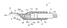
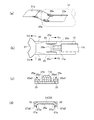
図1に示すように、本実施の形態のワイヤーハーネス1は、絶縁被覆された電線11と、その電線11の一端側に圧着接続された丸形の板端子である端子金具12と、電線11の端末部11eおよびこの端末部11eに結合された端子金具12の基端側部分12aを被覆する熱収縮チューブ13と、を含んで構成されている。
As shown in FIG. 1, the wire harness 1 of the present embodiment includes an insulated
電線11は、例えば高引張強度に合金化および調質されたアルミニウム製の複数の素線からなる導体部11aと、その導体部11aを長さ方向のほぼ全域で絶縁被覆する被覆材11b(外皮)とを有する被覆電線である。
The
電線11の導体部11aは、端子金具12の基端側部分12aに例えば超音波溶接されている。また、電線11の被覆材11bは、その一端側で導体部11aを取り囲みつつ、端子金具12の基端側部分12aに設けられた樹脂バレル12bによって端子金具12に圧着結合されている。
For example, the
電線11は、端子金具12が圧着された一端側であるいは他端側で、例えば図外の車両用の補機(例えば、スタータモータ、オルタネータ、バッテリ等)に接続されるようになっている。
The
端子金具12は、例えば銅または銅合金製の金属板をプレス加工により所定形状に成形したものである。
The
この端子金具12は、前記補機等の接続対象物に接触する外部接触面21aを形成する一端側の接触端子部21と、電線11の導体部11aに接触する内部接触面22aを形成する他端側の電線接続部22とを有している。
This terminal metal fitting 12 forms the
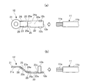
具体的には、図2(a)および図2(b)に示すように、端子金具12の接触端子部21は、丸形座金状(円環板状)をなしており、その片面側または両面側に円環状の外部接触面21aを有している。
Specifically, as shown in FIGS. 2 (a) and 2 (b), the
また、端子金具12の基端側部分12aには、電線11の導体部11aに接触する片面すなわち内部接触面22a側で導体部11aに超音波溶接された電線接続部22と、図3(a)および図3(b)に示すように、電線11の被覆材11bの端部近傍の外周面に圧着する状態にかしめられた樹脂バレル部12bとが設けられている。
Further, the base
熱収縮チューブ13は、端子金具12の電線接続部22と、電線11の導体部11aおよび被覆材11bの端末部11eを被覆する接着剤付のもので、熱収縮により電線11および端子金具12の電気接続および機械的結合部分の外面形状に応じて周方向に隙間なく熱収縮している。
The
また、熱収縮チューブ13の内方の接着剤層13aは、いわゆるホットメルト(登録商標)タイプの接着剤の硬化層で構成されている。この熱収縮チューブ13の接着剤層13aは、熱収縮チューブ13の熱収縮のための加熱に際して、熱収縮チューブ13の熱収縮温度より低い温度で低粘度に溶剤化し、導体部11aの複数の素線間の隙間や、電線11の端末部11eにおける導体部11aと被覆材11bの間の隙間に浸透した状態で、冷却されて硬化している。
The inner
したがって、電線11の端末部11eと端子金具12の電線接続部22との電気的接続部分となるワイヤーハーネスの長さ方向の特定区間Zにおいて、電線11の端末部11eおよび端子金具12の電線接続部22が、接着剤付の熱収縮チューブ13によって防水可能に被覆されている。
Therefore, in the specific section Z of the length direction of the wire harness used as the electrical connection part of the
なお、熱収縮チューブ13の熱収縮に際しては、熱収縮チューブ13が全体として均熱加熱されてもよいし、熱収縮チューブ13の長さ方向の端部側と中央側とで加熱条件や加熱のタイミングが異なってもよい。すなわち、熱収縮チューブ13の熱収縮の条件は、特に限定されるものではない。また、熱収縮チューブ13の熱収縮に際しての熱収縮率は、例えば約1/2であるが、それより高い熱収縮率でも低い熱収縮率でもよい。熱収縮前の熱収縮チューブ13は、電線11および端子金具12のサイズに応じて、長尺の接着剤付の熱収縮素材を所定長さに切断して作製される。
In the heat shrinkage of the
一方、端子金具12の接触端子部21は、熱収縮チューブ13から図1中の左方側に突出しており、端子金具12の接触端子部21と電線接続部22のうちの内部接触面22aを形成する平板状部分22cとは、電線11の径方向で異なる位置に離間している。
On the other hand, the
また、電線接続部22の内部接触面22aに対し端子金具12の反対面側に位置する接触端子部21の片面側の外部接触面21aは、例えば端子金具12の内部接触面22aよりも電線11の中心軸線Cに近接している。
Moreover, the
そして、端子金具12の接触端子部21と電線接続部22との間には、外部接触面21aおよび内部接触面22aの双方に対して交差するように傾斜する傾斜壁面部23が設けられている。
And between the
端子金具12の傾斜壁面部23は、接触端子部21および電線接続部22に対してそれぞれ曲げ加工された略帯状の金属板形状をなしている。
The inclined
また、電線接続部22および傾斜壁面部23は、端子金具12を形成する金属板の片面側に、電線接続部22の内部接触面22aと傾斜壁面部23の図1中で上方側の片面23aとに連続する曲げ内側面24aを形成している。この曲げ内側面24aは、内部接触面22aから傾斜壁面部23の片面23aに連続する湾曲面または屈曲面である。
Further, the electric
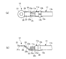
この曲げ内側面24aの幅方向(図2(a)中で上下方向)の両側には、電線接続部22および傾斜壁面部23の間で、それぞれ端子金具12の長手方向に延在しつつ傾斜壁面部23の片面23aと電線接続部22の内部接触面22aとの双方に対し交差するように曲げ内側面24aの曲げ内側に突き出た一対のリブ面25aが形成されている。
Inclined while extending in the longitudinal direction of the terminal fitting 12 between the electric
より具体的には、図5(a)ないし図5(c)に示すように、端子金具12の一対のリブ面25aは、曲げ内側面24aと共に、電線接続部22と傾斜壁面部23の間の曲げ加工部分に曲げ内側(図5(c)中で上側)に開く凹状をなす略三角形の内側壁面部分25a1と、曲げ内側面24aよりその曲げの内方側に入り込んで傾斜壁面部23の片面23aと電線接続部22の内部接触面22aとの双方に対し傾斜する略平坦な傾斜面部分25a2とを含んでいる。
More specifically, as shown in FIGS. 5 (a) to 5 (c), the pair of
そして、端子金具12は、両リブ面25aに対応する図5(c)中で左右一対の略L字形横断面のリブ25を有し、両リブ25によって傾斜壁面部23の一端側における板厚方向の曲げに対する曲げ剛性が高められている。なお、両リブ25は、ここでは略L字形の横断面としているが、略三角形の内側壁面部分25a1が電線接続部22と傾斜壁面部23の幅歩行両端に近接し、両リブ25は、傾斜壁面部23の片面23aと電線接続部22の内部接触面22aとの双方に対し交差するように幅方向外側に傾斜した形状となっていてもよい。
The
本実施の形態では、さらに、端子金具12の傾斜壁面部23が、図5(d)に示すように、端子金具12の内部接触面22aに対し反対面側で接触端子部21の外部接触面21aに連続する端子側曲げ内側面26aと、その端子側曲げ内側面26aの幅方向の両側で端子金具12の長手方向に延在しつつ前記反対面側における傾斜壁面部23の片面23bと外部接触面21aとの双方に対し傾斜するように端子側曲げ内側面26aの曲げ内側に突き出た端子側リブ面27aとを有している。
In the present embodiment, the inclined
端子金具12の一対の端子側リブ面27aは、端子側曲げ内側面26aと共に、接触端子部21と傾斜壁面部23の間の曲げ加工部分に曲げ内側(図5(d)中で下側)に開く凹状をなす略三角形の内側壁面部分27a1と、端子側曲げ内側面26aよりその曲げの内方側に入り込んで傾斜壁面部23の片面23bと接触端子部21の外部接触面21aとの双方に対し傾斜する略平坦な細幅の傾斜面部分27a2とを含んでいる。
The pair of terminal side rib surfaces 27a of the terminal fitting 12 are bent inside the bent portion between the
そして、端子金具12は、両リブ面27aに対応する図5(d)中で左右一対のリブ28を有し、両リブ28によって傾斜壁面部23の他端側における板厚方向の曲げに対する曲げ剛性が高められている。
The
熱収縮チューブ13は、このような端子金具12の傾斜壁面部23のうち接触端子部21側の壁面部23dの周囲に、電線接続部22の周囲を取り囲む中央側収縮部13cより小径に収縮している一端側収縮部13bを有している。
The heat-
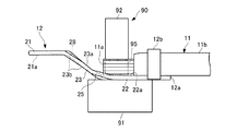
なお、電線11の導体部11aと端子金具12とを接続するための超音波溶接は、電線11の端末部11eを端子金具12に圧着した状態で行なわれる。
The ultrasonic welding for connecting the
この超音波溶接に際しては、図4に示すように、超音波溶接機90ベッド91上に電線11の導体部11aおよび端子金具12を載置し、端子金具12の内部接触面22a上で電線11の導体部11aを同図中に仮想線で示すサイドガイド治具95によって径方向の両側から所定幅内に拘束する。そして、超音波溶接機90の超音波ホーン92を用いて導体部11aおよび端子金具12に対し振動および圧力を加えながら、導体部11aおよび端子金具12を超音波溶接する。
In this ultrasonic welding, as shown in FIG. 4, the
次に、作用を説明する。 Next, the operation will be described.
上述のように構成された本実施の形態のワイヤーハーネスの接続端子構造においては、傾斜壁面部23が端子金具12の電線接続部22より接触端子部21側に熱収縮チューブ13の一端側収縮部13bの開口を塞ぐように設けられることになる。したがって、接着剤付の熱収縮チューブ13の熱収縮時に、熱収縮チューブ13の内部から溶けた接着剤が漏れ出し難くなり、接着剤が接触端子部21側に付着し難くなる。
In the connection terminal structure of the wire harness of the present embodiment configured as described above, the inclined
しかも、電線11の導体に接触する内部接触面22aに対して接触端子部21側の外部接触面21aが電線11の中心軸線C側に位置するので、接触端子部21側の外部接触面21aを電線接続部22の内部接触面22aに対し鉛直上方側に容易に配置でき、熱収縮チューブ13の内部で溶けた接着剤が接触端子部21側により漏れ出し難くなる。
Moreover, since the
したがって、端子金具12の幅方向中央部に複雑な加工部位を集中させることなく、電線11の長さ方向における接触端子部21の外部接触面21aと電線接続部22の内部接触面22aとの離間距離を抑えながら、接触端子部21側への接着剤の付着を有効に防止できる。その結果、電気接続用の端子金具12の加工や特性に悪影響を与えることなく、その端子金具12の長さを確実に短縮できるワイヤーハーネスの接続端子構造となる。
Therefore, without concentrating a complicated processing part at the center in the width direction of the terminal fitting 12, the separation between the
また、本実施の形態においては、熱収縮チューブ13が、端子金具12の傾斜壁面部23のうち接触端子部21側の壁面部23dの周囲に一端側収縮部13bを有しているので、傾斜壁面部23の電線接続部22側の片面23aが接触端子部21に近い側で熱収縮チューブ13の一端側の内周部分と近接することになる。したがって、熱収縮チューブ13の熱収縮時にこの近接部分が早期に閉じることで、熱収縮チューブ13の内部で溶けた接着剤が接触端子部21側に漏れ出し難くなる。
Moreover, in this Embodiment, since the
さらに、本実施の形態においては、端子金具12の傾斜壁面部23が、電線接続部22および接触端子部21に対しそれぞれ曲げ加工された略帯状の金属板で構成され、電線接続部22および傾斜壁面部23が、その金属板の片面側の曲げ内側面24aと、その幅方向の両側に位置する一対のリブ面25aとを有している。
Furthermore, in the present embodiment, the inclined
したがって、端子金具12の曲げ部を補強しつつその両端の突出を一対のリブ面25aの背面側で抑えて、熱収縮チューブ13の熱収縮時における一端側収縮部13bの開口を早期に縮小させることができる。
Therefore, the bent portion of the terminal fitting 12 is reinforced and protrusions at both ends thereof are suppressed on the back side of the pair of
加えて、本実施の形態においては、端子金具12の傾斜壁面部23が、端子金具12の内部接触面22aに対し反対面側で接触端子部21の外部接触面21aに連続する端子側曲げ内側面26aと、その端子側曲げ内側面26aの幅方向の両側に位置する一対の端子側リブ面27aとを有している。したがって、傾斜壁面部23の電線接続部22側の片面23aと熱収縮チューブ13との熱収縮時における密着性が高まるとともに、端子金具12の板厚方向の曲げに対する曲げ剛性も高められる。したがって、熱収縮チューブ13の内部で溶けた接着剤が接触端子部21側により漏れ出し難くなる。
In addition, in the present embodiment, the inclined
また、本実施の形態のようにアルミニウムを用いた電線によりワイヤーハーネスを作製する場合、銅系の端子金具12とアルミニウム系の導体部11aとの接触部付近における接着面は腐食防止にも寄与するが、本実施の形態では、端子金具12を長さ方向に短くして腐食防止のための接着面積をも有効に縮小できるとともに、接着剤の漏出規制のために端子金具12の幅方向中央部に複雑な加工部位が集中することがない。
In addition, when a wire harness is manufactured using an aluminum-based electric wire as in the present embodiment, the adhesion surface in the vicinity of the contact portion between the copper-based terminal fitting 12 and the aluminum-based
このように、本実施の形態のワイヤーハーネスの接続端子構造においては、電気接続用の端子金具12の加工や特性に悪影響を与えることなく、接着剤の接触端子部21側への流動および付着を防止でき、しかも、端子金具12の長さを確実に短縮できるワイヤーハーネスの接続端子構造を提供することができる。
Thus, in the connection terminal structure of the wire harness of the present embodiment, the adhesive flows and adheres to the
(第2の実施の形態)
図6は、本発明の第2の実施の形態に係るワイヤーハーネスの接続端子構造を示している。
(Second Embodiment)
FIG. 6 shows a connection terminal structure of a wire harness according to the second embodiment of the present invention.
なお、本実施の形態は、上述の第1の実施の形態とは端子金具の形状が相違するものの、他の構成については第1の実施の形態と同一または類似するものである。したがって、以下、第1の実施の形態と同一または類似する構成については図1ないし図6に示した第1の実施の形態中の対応する構成要素の符号を用いつつ、第1の実施の形態との相違点について説明する。 Although the present embodiment is different from the first embodiment in the shape of the terminal fitting, the other configurations are the same as or similar to the first embodiment. Therefore, hereinafter, for the same or similar configuration as the first embodiment, the reference numerals of the corresponding components in the first embodiment shown in FIGS. 1 to 6 are used, and the first embodiment is used. Differences from the above will be described.
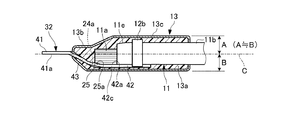
図6に示す本実施の形態のワイヤーハーネスの接続端子構造においては、第1の実施の形態における端子金具12に代えて、端子金具32が設けられている。 In the connection terminal structure of the wire harness of the present embodiment shown in FIG. 6, a terminal fitting 32 is provided instead of the terminal fitting 12 in the first embodiment.
この端子金具32は、例えば銅または銅合金製の金属板をプレス加工により所定形状に成形したもので、前記補機等の接続対象物に接触する一端側の接触端子部41と、電線11の導体部11aに接触する他端側の電線接続部42とを有している。
This terminal metal fitting 32 is formed by pressing a metal plate made of, for example, copper or copper alloy into a predetermined shape by press working, and a
端子金具32の接触端子部41は、丸形座金状(円環板状)をなしており、その片面側または両面側に円環状の外部接触面41aを有している。
The
また、端子金具32の電線接続部42は、電線11の導体部11aに接触する片面すなわち内部接触面42a側で導体部11aに超音波溶接されるとともに、樹脂バレル部12bによって電線11の被覆材11bの端部近傍の外周面に圧着する状態にかしめられている。
Further, the
一方、端子金具32の接触端子部41は、熱収縮チューブ13から図6中の左方側に突出しており、接触端子部41と電線接続部42のうちの内部接触面42aを形成する平板状部分42cとは、電線11の径方向で異なる位置に離間している。
On the other hand, the
また、電線接続部42の内部接触面42aとは反対面側に位置する接触端子部41の片面側の外部接触面41aは、電線接続部42の内部接触面42aよりも電線11の中心軸線Cに近接しており、あるいは、中心軸線C上に位置している。この場合、接触端子部41の外部接触面41aと直交する電線11の径方向において、電線11の中心軸線Cから熱収縮チューブ13の外周面の上端までの距離Aと下端までの距離Bとは略同一となる。
In addition, the
そして、端子金具32の接触端子部41と電線接続部42との間には、外部接触面41aおよび内部接触面42aの双方に対して交差するように傾斜する傾斜壁面部43が設けられている。
And between the
この傾斜壁面部43は、接触端子部41および電線接続部42に対してそれぞれ曲げ加工された略帯状の金属板形状をなしている。
The inclined
また、電線接続部42および傾斜壁面部43は、第1の実施の形態における電線接続部22および傾斜壁面部23と略同様に、電線接続部42の内部接触面42aと傾斜壁面部43の図6中で上方側の片面とに連続する曲げ内側面24aを形成している。
Moreover, the electric
さらに、曲げ内側面24aの幅方向の両側に、図5(b)に示した第1の実施の形態の場合と同様に、一対のリブ面25aやリブ25が形成され、端子金具32の板厚方向の曲げに対する曲げ剛性が強化されている。
Further, a pair of
本実施の形態においても、端子金具32の幅方向中央部に複雑な加工部位を集中させることなく、電線11の長さ方向における接触端子部41の外部接触面41aと電線接続部42の内部接触面42aとの離間距離を抑えながら、接触端子部41側への接着剤の付着を有効に防止できる。その結果、第1の実施の形態と同様の効果を得ることができる。
Also in the present embodiment, the internal contact between the
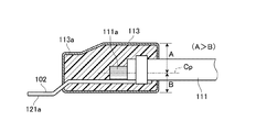
ちなみに、図7に示す比較例のように、端子金具102が電線111の中心軸線Cpから大きく離れる場合、熱収縮チューブ113の一端側収縮部113aの開口が、端子金具102によって広げられることとなり、熱収縮チューブ113の内周側の接着剤が端子金具102の外部接触面121a側に漏れ出し易くなってしまうことになる。
Incidentally, as in the comparative example shown in FIG. 7, when the
なお、上述の各実施においては、電線11の導体部11aを端子金具12、32に超音波溶接するものとしたが、電線11の導体部11aまたは/および端子金具12、32の材料や性質に応じて、超音波溶着でなく抵抗溶接を採用したり、かしめ(ワイヤバレルのかしめによる圧着)を用いたりすることができることはいうまでもない。
In each implementation described above, the
また、端子金具12、32の接触端子部21、41の端子形状が円環板状でなく、公知の各種の端子形状を採り得ることはいうまでもなく、端子金具12、32の電線接続部22、42の内部接触面22a、42aが必ずしも平坦でなく、略U字形や円形に湾曲してもよいことも勿論である。
Needless to say, the terminal shape of the
以上説明したように、本発明は、電気接続用の端子金具の加工や特性に悪影響を与えることなく、接着剤の接触端子部側への流動および付着を防止でき、しかも、端子金具の長さを確実に短縮できるワイヤーハーネスの接続端子構造を提供することができるものであり、接続端子が接続された電線端末部を熱収縮チューブで被覆し防水処理したワイヤーハーネスの接続端子構造全般に有用である。 As described above, the present invention can prevent the adhesive from flowing and adhering to the contact terminal portion side without adversely affecting the processing and characteristics of the terminal fitting for electrical connection, and the length of the terminal fitting. It is possible to provide a wire harness connection terminal structure that can be reliably shortened, and is useful for all wire harness connection terminal structures that are covered with a heat-shrinkable tube and are waterproofed. is there.
11 電線
11a 導体部
11b 被覆材
11e 端末部(導体の端部および被覆の端部)
12、32 端子金具
12a 基端側部分
12b 樹脂バレル
13 熱収縮チューブ
13a 接着剤層
13b 一端側収縮部
13c 中央側収縮部
21、41 接触端子部
21a、41a 外部接触面
22、42 電線接続部
22a、42a 内部接触面
22c、42c 平板状部分
23、43 傾斜壁面部
23a 片面(内部接触面側の片面、金属板の片面)
23b 片面(外部接触面側の片面、金属板の反対面側の片面)
23d 接触端子部側の壁面部
24a 曲げ内側面
25 リブ(一対のリブ)
25a リブ面
25a1 内側壁面部分
25a2 傾斜面部分
26a 端子側曲げ内側面
27a 端子側リブ面(一対の端子側リブ面)
27a1 内側壁面部分
27a2 傾斜面部分
28 リブ
90 超音波溶接機
91 ベッド
92 超音波ホーン
95 サイドガイド治具
11
12, 32 Terminal fitting 12a
23b one side (one side on the external contact side, one side on the opposite side of the metal plate)
23d Wall surface portion on the side of the
25a Rib surface 25a1 Inner wall surface portion 25a2
27a1 Inner wall surface portion 27a2
Claims (4)
前記端子金具の前記電線接続部と前記導体の端部および前記被覆の端部とを被覆する接着剤付の熱収縮チューブと、を備えたワイヤーハーネスの接続端子構造であって、
前記端子金具の前記外部接触面が、前記端子金具の前記内部接触面よりも前記電線の中心軸線に近接しており、
前記端子金具の前記電線接続部と前記端子金具の前記接触端子部との間に、前記外部接触面および前記内部接触面の双方に対して交差するように傾斜する傾斜壁面部が設けられていることを特徴とするワイヤーハーネスの接続端子構造。 A terminal fitting having a contact terminal portion on one end side that forms an external contact surface that comes into contact with an object to be connected and an electric wire connection portion on the other end side that forms an internal contact surface that comes into contact with a conductor of an electric wire covered with insulation by an outer sheath; ,
A wire harness connection terminal structure comprising a heat-shrinkable tube with an adhesive that covers the wire connection portion of the terminal fitting and the end portion of the conductor and the end portion of the covering,
The external contact surface of the terminal fitting is closer to the central axis of the wire than the internal contact surface of the terminal fitting;
Between the wire connecting portion of the terminal fitting and the contact terminal portion of the terminal fitting, there is provided an inclined wall portion that is inclined so as to intersect both the external contact surface and the internal contact surface. The connection terminal structure of the wire harness characterized by the above-mentioned.
前記端子金具の前記電線接続部および前記傾斜壁面部が、前記金属板の片面側で前記電線接続部の前記内部接触面と前記傾斜壁面部の片面とに連続するように形成された曲げ内側面と、該曲げ内側面の幅方向の両側で前記端子金具の長手方向に延在しつつ前記傾斜壁面部の片面と前記内部接触面との双方に対し傾斜するように前記曲げ内側面の曲げ内側に突き出たリブ面と、を有していることを特徴とする請求項1または2に記載のワイヤーハーネスの接続端子構造。 The inclined wall surface portion of the terminal fitting is composed of a substantially band-shaped metal plate that is bent with respect to the wire connection portion and the contact terminal portion, respectively.
A bent inner surface formed so that the electric wire connecting portion and the inclined wall surface portion of the terminal fitting are continuous with the inner contact surface of the electric wire connecting portion and one surface of the inclined wall surface portion on one side of the metal plate. And bending inner side of the bending inner side surface so as to be inclined with respect to both one side of the inclined wall surface part and the inner contact surface while extending in the longitudinal direction of the terminal fitting on both sides in the width direction of the bending inner side surface. The wire harness connection terminal structure according to claim 1, further comprising: a rib surface protruding into the wire harness.
Priority Applications (1)
| Application Number | Priority Date | Filing Date | Title |
|---|---|---|---|
| JP2014248899A JP2016110901A (en) | 2014-12-09 | 2014-12-09 | Connection terminal structure for wiring harness |
Applications Claiming Priority (1)
| Application Number | Priority Date | Filing Date | Title |
|---|---|---|---|
| JP2014248899A JP2016110901A (en) | 2014-12-09 | 2014-12-09 | Connection terminal structure for wiring harness |
Publications (1)
| Publication Number | Publication Date |
|---|---|
| JP2016110901A true JP2016110901A (en) | 2016-06-20 |
Family
ID=56124703
Family Applications (1)
| Application Number | Title | Priority Date | Filing Date |
|---|---|---|---|
| JP2014248899A Pending JP2016110901A (en) | 2014-12-09 | 2014-12-09 | Connection terminal structure for wiring harness |
Country Status (1)
| Country | Link |
|---|---|
| JP (1) | JP2016110901A (en) |
Cited By (5)
| Publication number | Priority date | Publication date | Assignee | Title |
|---|---|---|---|---|
| CN108011201A (en) * | 2017-12-19 | 2018-05-08 | 上海晗普新材料科技有限公司 | A kind of staged heat shrinkable terminal |
| JP2019096473A (en) * | 2017-11-22 | 2019-06-20 | 矢崎総業株式会社 | Wire with terminal |
| CN110824214A (en) * | 2019-12-06 | 2020-02-21 | 林毓松 | A power meter box fixed assembly external lead wiring device |
| CN111564706A (en) * | 2019-02-14 | 2020-08-21 | 住友电装株式会社 | Ground terminal and wire harness |
| JP2020135963A (en) * | 2019-02-14 | 2020-08-31 | 住友電装株式会社 | Earth terminal and wire harness |
-
2014
- 2014-12-09 JP JP2014248899A patent/JP2016110901A/en active Pending
Cited By (9)
| Publication number | Priority date | Publication date | Assignee | Title |
|---|---|---|---|---|
| JP2019096473A (en) * | 2017-11-22 | 2019-06-20 | 矢崎総業株式会社 | Wire with terminal |
| CN108011201A (en) * | 2017-12-19 | 2018-05-08 | 上海晗普新材料科技有限公司 | A kind of staged heat shrinkable terminal |
| CN108011201B (en) * | 2017-12-19 | 2023-08-29 | 苏州晗普新材料科技有限公司 | Stepped heat shrinkage terminal |
| CN111564706A (en) * | 2019-02-14 | 2020-08-21 | 住友电装株式会社 | Ground terminal and wire harness |
| JP2020135963A (en) * | 2019-02-14 | 2020-08-31 | 住友電装株式会社 | Earth terminal and wire harness |
| JP2020135964A (en) * | 2019-02-14 | 2020-08-31 | 住友電装株式会社 | Ground terminal and wire harness |
| CN113366706A (en) * | 2019-02-14 | 2021-09-07 | 住友电装株式会社 | Ground terminal and wire harness |
| JP7286993B2 (en) | 2019-02-14 | 2023-06-06 | 住友電装株式会社 | Ground terminal and wire harness |
| CN110824214A (en) * | 2019-12-06 | 2020-02-21 | 林毓松 | A power meter box fixed assembly external lead wiring device |
Similar Documents
| Publication | Publication Date | Title |
|---|---|---|
| JP5860618B2 (en) | Wire connection method | |
| JP5820153B2 (en) | Inter-wire connection structure and manufacturing method thereof | |
| US9379460B2 (en) | Terminal welded and crimped to a wire and a shrinkable tube covering the wire and the terminal | |
| CN111210927B (en) | Conductive member | |
| US10319497B2 (en) | Molded portion-equipped electric cable and method for manufacturing molded portion-equipped electric cable | |
| WO2015093247A1 (en) | Terminal for electrical wire connection and electrical wire connection structure of said terminal | |
| JP4720168B2 (en) | Shielded wire | |
| JP6142807B2 (en) | Wire Harness | |
| JP2016110901A (en) | Connection terminal structure for wiring harness | |
| JP5369637B2 (en) | Electric wire with terminal fitting and method for manufacturing the same | |
| JP6996974B2 (en) | Manufacturing method of electric wire with terminal and electric wire with terminal | |
| US10348002B2 (en) | Wiring member having molded part | |
| JP2017084600A (en) | Wire with terminal and manufacturing method of wire with terminal | |
| JP6417738B2 (en) | Wire Harness | |
| JP5907119B2 (en) | Wire harness manufacturing method and wire harness | |
| US20180331485A1 (en) | Method of manufacturing terminal-equipped conductive member, conductive member, and terminal-equipped wire | |
| JP2017162757A (en) | Terminal waterproof structure of wire harness | |
| WO2017179410A1 (en) | Electric cable with molded portion | |
| JP5527376B2 (en) | Shielded wire | |
| JP2016001542A (en) | Electric wire with terminal | |
| JP5168016B2 (en) | Shielded wire | |
| JP2020089120A (en) | Method and structure of aluminum wire connection | |
| JP2015076329A (en) | Electric wire with terminal | |
| JP2012256440A (en) | Electric wire with terminal metal fitting, and terminal metal fitting | |
| JP2014229572A (en) | Wire with terminal |