JP6495351B2 - Mounting member structure - Google Patents
Mounting member structure Download PDFInfo
- Publication number
- JP6495351B2 JP6495351B2 JP2017007649A JP2017007649A JP6495351B2 JP 6495351 B2 JP6495351 B2 JP 6495351B2 JP 2017007649 A JP2017007649 A JP 2017007649A JP 2017007649 A JP2017007649 A JP 2017007649A JP 6495351 B2 JP6495351 B2 JP 6495351B2
- Authority
- JP
- Japan
- Prior art keywords
- mounting member
- mass
- opening
- bolt
- weight
- Prior art date
- Legal status (The legal status is an assumption and is not a legal conclusion. Google has not performed a legal analysis and makes no representation as to the accuracy of the status listed.)
- Expired - Fee Related
Links
Images


Classifications
-
- B—PERFORMING OPERATIONS; TRANSPORTING
- B60—VEHICLES IN GENERAL
- B60K—ARRANGEMENT OR MOUNTING OF PROPULSION UNITS OR OF TRANSMISSIONS IN VEHICLES; ARRANGEMENT OR MOUNTING OF PLURAL DIVERSE PRIME-MOVERS IN VEHICLES; AUXILIARY DRIVES FOR VEHICLES; INSTRUMENTATION OR DASHBOARDS FOR VEHICLES; ARRANGEMENTS IN CONNECTION WITH COOLING, AIR INTAKE, GAS EXHAUST OR FUEL SUPPLY OF PROPULSION UNITS IN VEHICLES
- B60K5/00—Arrangement or mounting of internal-combustion or jet-propulsion units
- B60K5/12—Arrangement of engine supports
- B60K5/1266—Supports comprising friction damping devices
-
- B—PERFORMING OPERATIONS; TRANSPORTING
- B60—VEHICLES IN GENERAL
- B60K—ARRANGEMENT OR MOUNTING OF PROPULSION UNITS OR OF TRANSMISSIONS IN VEHICLES; ARRANGEMENT OR MOUNTING OF PLURAL DIVERSE PRIME-MOVERS IN VEHICLES; AUXILIARY DRIVES FOR VEHICLES; INSTRUMENTATION OR DASHBOARDS FOR VEHICLES; ARRANGEMENTS IN CONNECTION WITH COOLING, AIR INTAKE, GAS EXHAUST OR FUEL SUPPLY OF PROPULSION UNITS IN VEHICLES
- B60K5/00—Arrangement or mounting of internal-combustion or jet-propulsion units
- B60K5/12—Arrangement of engine supports
- B60K5/1208—Resilient supports
- B60K5/1216—Resilient supports characterised by the location of the supports relative to the motor or to each other
-
- F—MECHANICAL ENGINEERING; LIGHTING; HEATING; WEAPONS; BLASTING
- F16—ENGINEERING ELEMENTS AND UNITS; GENERAL MEASURES FOR PRODUCING AND MAINTAINING EFFECTIVE FUNCTIONING OF MACHINES OR INSTALLATIONS; THERMAL INSULATION IN GENERAL
- F16F—SPRINGS; SHOCK-ABSORBERS; MEANS FOR DAMPING VIBRATION
- F16F7/00—Vibration-dampers; Shock-absorbers
- F16F7/10—Vibration-dampers; Shock-absorbers using inertia effect
- F16F7/104—Vibration-dampers; Shock-absorbers using inertia effect the inertia member being resiliently mounted
- F16F7/108—Vibration-dampers; Shock-absorbers using inertia effect the inertia member being resiliently mounted on plastics springs
Description
本発明は、駆動源に取り付けられて、駆動源を支持する取付部材構造体に関する。 The present invention relates to an attachment member structure that is attached to a drive source and supports the drive source.
例えば、特許文献1には、ダイナミックダンパを、エンジンマウントの横側の一方に延出する方向にボルトで締結したダイナミックダンパの取付構造が開示されている。特許文献1に開示された取付構造では、さらに、このボルトを介して、ダイナミックダンパを車体側ブラケットと共締めしている。 For example, Patent Document 1 discloses a dynamic damper mounting structure in which a dynamic damper is fastened with a bolt in a direction extending to one side of an engine mount. In the mounting structure disclosed in Patent Document 1, the dynamic damper is fastened together with the vehicle body side bracket via the bolt.
しかしながら、特許文献1に開示された取付構造では、エンジンマウントの横側の一方にのみダイナミックダンパ(又は、重量マス)が配置されることで、サブフレームを平面視して左右非対称に構成されている。このため、エンジン側から入力される振動によって、ダイナミックダンパが不安定な振動を発生させるおそれがある。 However, in the mounting structure disclosed in Patent Document 1, a dynamic damper (or a weight mass) is arranged only on one side of the engine mount, so that the subframe is asymmetrical in plan view. Yes. For this reason, the dynamic damper may generate unstable vibration due to vibration input from the engine side.
具体的には、エンジンで発生した振動が、エンジンから順次、エンジン側ブラケット、マウント、車体側ブラケットを介して車体フレームに伝達される際、このような振動伝達経路から逸脱した位置にダイナミックダンパ(又は、重量マス)が配置されることで、ダイナミックダンパ(又は、重量マス)が不安定な振動を発生させるおそれがある。この不安定な振動は、例えば、車体側ブラケットの先端が最も振動し、上下方向に振動(最大振幅箇所)する場合がある。その振動軸から離間した部位では、回転モーメントの発生によって異なるモードを励起するおそれがある。また、固有値が上下モードの他に、ねじれモード等の異なる振動方向の固有値を励起するおそれがある。 Specifically, when vibration generated in the engine is sequentially transmitted from the engine to the vehicle body frame via the engine side bracket, the mount, and the vehicle body side bracket, the dynamic damper ( Alternatively, the dynamic damper (or the weight mass) may generate unstable vibration by arranging the weight mass). This unstable vibration may be, for example, that the tip of the vehicle body side bracket vibrates most and vibrates vertically (maximum amplitude location). In a part separated from the vibration axis, different modes may be excited by the generation of a rotational moment. In addition to the up / down mode, the eigenvalue may excite eigenvalues in different vibration directions such as a torsion mode.
また、特許文献1に開示された取付構造では、ダイナミックダンパ(又は、重量マス)が車体側ブラケットの外部に露出した状態となることで、ダイナミックダンパ(又は、重量マス)の脱落を想定したフェルセーフを行う必要性がある。 Further, in the mounting structure disclosed in Patent Document 1, the dynamic damper (or weight mass) is exposed to the outside of the vehicle body side bracket, so that the dynamic damper (or weight mass) is assumed to fall off. There is a need to do safe.
本発明は、前記の点に鑑みてなされたものであり、エンジンマウントの不安定な振動を抑制することが可能な取付部材構造体を提供することを目的とする。 The present invention has been made in view of the above points, and an object of the present invention is to provide an attachment member structure capable of suppressing unstable vibration of an engine mount.
前記の目的を達成するために、本発明は、車両の駆動源を含むパワープラントに取り付けられ、前記パワープラントと防振装置との間に配置される取付部材を備えた取付部材構造体であって、前記取付部材は、前記パワープラントに当接する開口部と、前記開口部から連続する内部空間部とを有し、前記内部空間部内には、重量マスが配置され、前記重量マスは、固定部材を介して前記取付部材に固定され、前記固定部材は、前記重量マスを前記取付部材に対して締結する第1ボルトからなり、前記取付部材は、前記防振装置に対して第2ボルトによって締結され、前記第1ボルトと前記第2ボルトとは、同軸に配置されていることを特徴とする。 In order to achieve the above object, the present invention is an attachment member structure including an attachment member attached to a power plant including a vehicle drive source and disposed between the power plant and the vibration isolator. The mounting member has an opening that contacts the power plant and an internal space that continues from the opening. A weight mass is disposed in the internal space, and the weight mass is fixed. The fixing member is fixed to the mounting member via a member, and the fixing member includes a first bolt that fastens the weight mass to the mounting member. The mounting member is connected to the vibration isolator by a second bolt. The first bolt and the second bolt are fastened and arranged coaxially .
本発明では、エンジンマウントの不安定な振動を抑制することが可能な取付部材構造体を得ることができる。 In the present invention, it is possible to obtain an attachment member structure capable of suppressing unstable vibration of the engine mount.
次に、本発明の実施形態について、適宜図面を参照しながら詳細に説明する。図1は、本発明の実施形態に係る振動体支持構造が適用されたサブフレームの平面図である。なお、各図中において、「前後」は、車両前後方向、「左右」は、車両左右方向(車幅方向)、「上下」は、鉛直上下方向をそれぞれ示している。 Next, embodiments of the present invention will be described in detail with reference to the drawings as appropriate. FIG. 1 is a plan view of a subframe to which a vibrating body support structure according to an embodiment of the present invention is applied. In each figure, “front and rear” indicates the vehicle longitudinal direction, “left and right” indicates the vehicle lateral direction (vehicle width direction), and “up and down” indicates the vertical vertical direction.
図1に示されるように、車両の車体前部側には、サブフレーム(車体フレーム)12が搭載されている。このサブフレーム12は、前部クロスメンバ14と、後部クロスメンバ16とから構成されている。前部クロスメンバ14の車幅方向に沿った両側部には、車両後方に向かって延在する前側左右サイド部18、18がそれぞれ対向配置されている。後部クロスメンバ16の車幅方向に沿った両側部には、車両前方に向かって延在して前側左右サイド部18、18と連結される後側左右サイド部20、20が設けられている。
As shown in FIG. 1, a sub-frame (body frame) 12 is mounted on the vehicle body front side. The
なお、本実施形態では、サブフレーム12として、前側左右サイド部18、18及び後側左右サイド部20、20を、それぞれ、前部クロスメンバ14及び後部クロスメンバ16と一体的に構成した場合を例示しているが、これに限定されるものではない。例えば、前側左サイド部18と後側左サイド部20とを一体成形して左サイドメンバ(図示せず)を構成すると共に、前側右サイド部18と後側右サイド部20とを一体成形して右サイドメンバ(図示せず)を構成するようにしてもよい。
In the present embodiment, as the
前部クロスメンバ14は、車両の車幅方向に沿って延在しパワーユニットPの前側に配置されている。後部クロスメンバ16は、車両の車幅方向に沿って延在し、パワーユニットPの後側に配置されている。前側左サイド部18及び後側左サイド部20は、平面視して車両の前後方向に沿って延在し、パワーユニットPの左側に配置されている。前側右サイド部18及び後ろ側右サイド部20は、平面視して車両の前後方向に沿って延在し、パワーユニットPの右側に配置されている。
The
サブフレーム12は、前部クロスメンバ14、後部クロスメンバ16の前側及び後側左右サイド部18、18、20、20同士を、例えば、溶接等によって一体的に固定することで、平面視して略井桁構造を呈している。なお、サブフレーム12は、略井桁構造に限定されるものではなく、例えば、左右サイドメンバに対して単一のクロスメンバで構成される場合であってもよい。
The
パワーユニットPは、例えば、エンジンE(駆動源、振動発生源)及びトランスミッションが一体的に構成されたユニットからなり、サブフレーム12によってフローティング支持されている。
The power unit P includes, for example, a unit in which an engine E (drive source, vibration generation source) and a transmission are integrally formed, and is floatingly supported by the
サブフレーム12には、エンジンEをフローティング支持するフローティング機構が配置されている。このフローティング機構は、前部クロスメンバ14に配置されるフロントマウント22と、後部クロスメンバ16の後側左サイド部20に配置されるサイドマウント24と、後部クロスメンバ16に配置されるリヤマウント26とから構成されている。エンジンEは、フロントマウント22、サイドマウント24、及び、リヤマウント26からなる3点でフローティング支持されている。
The
フロントマウント22には、取付金具28を介してエンジンEの車両前側を支持する防振装置100aが配置されている。この防振装置100aは、複数のボルト30及びフロントマウントブラケット32を介して、前部クロスメンバ14のフロントビームに対してリジットに固定されている。リヤマウント26には、後記する取付部材50を介してエンジンEの車両後側を支持する防振装置100bが配置されている。この防振装置100bは、複数のボルト36及びマウントブラケット38を介して、後部クロスメンバ16に対してフローティング支持されている。サイドマウント24には、取付金具40を介してエンジンEの車幅方向左側を支持する他の防振装置100cが配置されている。他の防振装置100cは、複数のボルトを介して後部クロスメンバ16の後側左サイド部20にリジットに固定されている。
An
フロント側の防振装置100aとリヤ側の防振装置100bとは、それぞれ略同一構成からなる。この防振装置の構成については、後記で詳細に説明する。
The front
図1に示されるように、リヤ側の防振装置100bは、マウントブラケット38によって支持されている。マウントブラケット38は、防振装置100bとサブフレーム12とを連結している。このマウントブラケット38は、支持固定部42と、2つの脚部とから構成されている。支持固定部42は、上面に防振装置100bがマウントされるマウント面を有し、固定ボルト46を介して防振装置100bがマウント面に支持固定されている。
As shown in FIG. 1, the
脚部は、支持固定部42の下方から車両前方に向かって分岐する前方脚部44aと、車両後方に向かって分岐する後方脚部44bとから構成されている。前方脚部44a及び後方脚部44bは、それぞれ、図示しない弾性ブッシュを介して、後部クロスメンバ16の上面にフローティング可能に取り付けられている。
The leg portion includes a
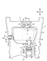
図2は、本実施形態に係る取付部材構造体の拡大断面図、図3は、第1変形例に係る取付部材構造体の拡大断面図、図4は、第2変形例に係る取付部材構造体の拡大断面図である。なお、図2〜図4において、「M」は、後記する図5に示される防振装置100bに配置される上部ブラケット112と、取付板部114とを併せたものを模式的に示したものである。この「M」は、例えば、アルミニウムや鋼材等によって一体的に形成されている。
2 is an enlarged cross-sectional view of the mounting member structure according to the present embodiment, FIG. 3 is an enlarged cross-sectional view of the mounting member structure according to the first modification, and FIG. 4 is a mounting member structure according to the second modification. It is an expanded sectional view of a body. 2 to 4, “M” schematically shows a combination of the
図1に示されるように、パワープラントPと防振装置100bとの間には、略ラッパ状からなる取付部材50が車両前後方向に沿って配置されている。取付部材50の車両前方端部は、駆動源Eを含むパワープラントPに取り付けられ、取付部材50の車両後方端部は、防振装置100bに連結されている。
As shown in FIG. 1, an
図2に示されるように、この取付部材50は、本体部52と、本体部52に連続する連結部54とが一体的に構成されている。本体部50は、車両前方端部に位置してパワープラントPに当接する開口部56と、開口部56から車両後方に連続する内部空間部58とを有する。連結部54は、開口部56の反対側に位置して防振装置100bと連結されている。内部空間部58には、防振装置100b側(連結部54側)に向かって窪む凹部60が形成されている。なお、取付部材50がパワープラントPに取り付けられた際、開口部56はパワープラントPによって閉塞された状態となる。
As shown in FIG. 2, the
内部空間部58内には、有底円筒体からなる重量マス62が配置されている。重量マス62は、有底円筒体からなり、車両前方端部にマス開口部64が形成され、車両後方端部にマス底部66が設けられている。マス開口部64とマス底部66との間には、マス開口部64に連続するマス凹部68が形成されている。
In the
重量マス62は、第1ボルト(固定部材)70及びワッシャ72を介して、凹部60の側壁74に締結(固定)されている。なお、重量マス62と凹部60の内壁76との間には、クリアランス78が形成されている。
The weight mass 62 is fastened (fixed) to the
第1ボルト70は、多角形状からなる頭部70aと、ねじ部70bとが一体的に構成されている。取付部材50は、防振装置100bの取付板部114に対して、第2ボルト80及びワッシャ82によって締結されている。第2ボルト80も、第1ボルト70と同様に、頭部80aと、ねじ部80bとが一体的に構成されている。
In the
第1ボルト70と第2ボルト80とは、連結部54において互いに同軸に配置され、且つ、連結部54を間にして互いに対向している。重量マス62のマス開口部64は、取付部材50の開口部56と同じ方向、すなわち、車両前方を臨む方向に配置されている。マス凹部68には、ワッシャ72を介して第1ボルト70の頭部70aが当接している。
The
重量マス62の形状は、図2に示される有底円筒体に限定されるものではない。例えば、図3の第1変形例に係る重量マス62aに示されるように、貫通孔84を有する円筒体86であってもよい。貫通孔84に沿って挿通される第1ボルト70及びワッシャ72によって、重量マス62aが凹部60に締結されている。
The shape of the weight mass 62 is not limited to the bottomed cylindrical body shown in FIG. For example, as shown in the
また、図4の第2変形例に示されるように、重量マス62、62aに代替してダイナミックダンパ88を内部空間部58内の凹部60に配置するようにしてもよい。
Further, as shown in the second modification of FIG. 4, the
このダイナミックダンパ88は、外径側に位置する錘90と、内径側に位置するダイナミックダンパブラケット92と、錘90とダイナミックダンパブラケット92とを弾性的に連結(例えば、加硫接着)する弾性連結体94とを有する。例えば、弾性連結体94の外径側は、錘90の内壁に加硫接着されていると共に、弾性連結体94の内径側も、ダイナミックダンパブラケット92の外周面に加硫接着されている。
The
錘90は、円筒体からなり、円筒体の外周面と凹部60の内壁との間には、クリアランス96が形成されている。ダイナミックダンパブラケット92は、貫通孔98を有する円筒体からなり、貫通孔98を挿通する第1ボルト70及びワッシャ72によって凹部60に締結されている。
The
次に、防振装置100b(100a)の構造及びその作用について説明する。
図5は、図1に示すサブフレームに搭載された防振装置の拡大断面図である。
なお、フロント側の防振装置100aとリヤ側の防振装置100bは、略同じ構造からなるため、リヤ側の防振装置100bの構造を詳細に説明してフロント側の防振装置100aの構造の説明を省略する。また、図6に示す防振装置100bでは、液封式が用いられているが、これに限定されるものではない。
Next, the structure and operation of the
FIG. 5 is an enlarged cross-sectional view of the vibration isolator mounted on the subframe shown in FIG.
Since the front-
図5に示されるように、防振装置100bは、下部ブラケット102と、ハウジング104とを備えて構成されている。下部ブラケット102は、ボルト46を介してマウントブラケット38(サブフレーム12)に固定されている。ハウジング104は、下部ブラケット102の中央部に設けられた円筒部106の貫通孔内に圧入されている。この防振装置100bは、サブフレーム12とエンジンE(振動発生源)との間に介装されて、エンジンEからサブフレーム12に伝達される振動を抑制するものである。
As shown in FIG. 5, the
ハウジング104には、環状凸部108を介して弾性部材110が装着されている。弾性部材110の上部には、上部ブラケット112が搭載されている。上部ブラケット112には、上方に向かって延在し、取付部材50(図1、図2参照)が取り付けられる取付板部114が設けられている。また、取付板部114の上方には、弓型状を呈し、車幅方向に沿って弾性部材110を跨ぐアーム部116が懸架されている。このアーム部116は、ボルト46を介して一組の左右取付部118に締結されている。
An
弾性部材110の内部には、空間部が形成されている。この空間部は、仕切り部材120によって上側の主液室(受圧室)122と、下側の副液室(平衡室)124とに区画されている。
A space is formed inside the
仕切り部材120は、上側仕切り部材120aと下側仕切り部材120bとによって構成されている。上側仕切り部材120aと下側仕切り部材120bとの間には、メンブラン(可動隔壁部)126が介装されている。また、上側仕切り部材120a及び下側仕切り部材120bの外径側には、主液室122と副液室124とを連通させるオリフィス通路128が設けられている。
The
仕切り部材120の下方には、副液室124を形成するためのダイヤフラム130が設けられている。ダイヤフラム130には、外周縁部の内部に対して加硫接合されたリング部材132が設けられている。ハウジング104の下部側を加締めてリング部材132を支持することで、ダイヤフラム130は、ハウジング104に固定されている。
A
主液室122、副液室124、及び、オリフィス通路128には、粘性を有する流体(非圧縮流体)が封入されている。防振装置100bに対して荷重(力)が入力されると、主液室122及び副液室124に封入された流体がオリフィス通路128を介して主液室122と副液室124との間を流動する。この流体の流動によって入力荷重が減衰される。
The main
本実施形態に係る取付部材構造体が組み付けられたサブフレーム12は、基本的に以上のように構成されるものであり、次にその作用効果について説明する。
The
本実施形態では、エンジンEで発生した振動(エンジン振動)が、マウントブラケット38を介してサブフレーム12に対して伝達される際、その振動伝達経路中に存在する取付部材50の内部空間部58内に重量マス62、62a又はダイナミックダンパ88を配置している。これにより、本実施形態では、エンジンマウント側の不安定な振動を抑制することができる。例えば、重量マス62、62aの場合には、エンジン振動による取付部材50の先端の励起振動を低減することができる。ダイナミックダンパ88の場合には、エンジン振動による取付部材50の先端の一部周波数帯の振動を低減することができる。重量マス62、62a又はダイナミックダンパ88のいずれの場合であっても、パワープラント室P内のレイアウトにおいて、従来構造と比較してレイアウトの自由度を向上させることができる。
In the present embodiment, when vibration (engine vibration) generated in the engine E is transmitted to the
また、本実施形態では、重量マス62、62a又はダイナミックダンパ88が取付部材50の内部空間部58内に配置されて外部に露出しない構造となっていると共に、取付部材50の開口部56がパワープラントPで閉塞されるようになっている。このため、本実施形態では、例えば、何らかの要因で重量マス62、62a又はダイナミックダンパ88が凹部60から離脱した場合であっても、重量マス62、62a又はダイナミックダンパ88が取付部材50の内部空間部58内に留まるようにフェルセーフが行われている。
In the present embodiment, the
さらに、本実施形態では、取付部材50の内部空間部58内に凹部60を形成することで、第1ボルト70を介して重量マス62、62a又はダイナミックダンパ88を凹部60に対して確実に締結(固定)することができる。
Further, in the present embodiment, by forming the
さらにまた、本実施形態では、重量マス62、62a又はダイナミックダンパ88を取付部材50に締結(固定)する第1ボルト70と、防振装置100bを取付部材50に締結(固定)する第2ボルト80とが同軸に配置されることで、エンジン側の振動を防振装置100bに対して円滑且つ安定して伝達することができる。
Furthermore, in the present embodiment, the
さらにまた、本実施形態では、取付部材50の開口部56と、重量マス62、62aのマス開口部64とをそれぞれ車両前方に向けて同じ方向とすることで、重量マス62、62aによる不安定な振動の発生を回避することができる。
Furthermore, in this embodiment, by making the
さらにまた、本実施形態では、パワープラントPと防振装置100bとの間に配置される取付部材50の内部空間部58内に対して重量マス62、62a又はダイナミックダンパ88を配置することで、重量マス62、62a又はダイナミックダンパ88を他の部位に配置した場合と比較して、パワープラント室内のスペースの効率化を達成することができる。
Furthermore, in this embodiment, by arranging the
50 取付部材
56 開口部
58 内部空間部
60 凹部
62、62a 重量マス
64 マス開口部
68 マス凹部
70 第1ボルト(固定部材)
70a 頭部
80 第2ボルト
88 ダイナミックダンパ
90 錘
92 ダイナミックダンパブラケット
94 弾性連結体
100b 防振装置
E エンジン(駆動源)
P パワープラント
50 mounting
P power plant
Claims (5)
前記取付部材は、前記パワープラントに当接する開口部と、前記開口部から連続する内部空間部とを有し、
前記内部空間部内には、重量マスが配置され、
前記重量マスは、固定部材を介して前記取付部材に固定され、
前記固定部材は、前記重量マスを前記取付部材に対して締結する第1ボルトからなり、
前記取付部材は、前記防振装置に対して第2ボルトによって締結され、
前記第1ボルトと前記第2ボルトとは、同軸に配置されていることを特徴とする取付部材構造体。 An attachment member structure including an attachment member attached to a power plant including a vehicle drive source and disposed between the power plant and the vibration isolator,
The mounting member has an opening that comes into contact with the power plant, and an internal space that continues from the opening,
A weight mass is disposed in the internal space,
The weight mass is fixed to the mounting member via a fixing member ,
The fixing member includes a first bolt that fastens the weight mass to the mounting member,
The mounting member is fastened to the vibration isolator by a second bolt,
The mounting member structure, wherein the first bolt and the second bolt are arranged coaxially .
前記内部空間部には、前記防振装置側に向かって窪む凹部が形成され、
前記重量マスは、前記凹部に固定されていることを特徴とする取付部材構造体。 The mounting member structure according to claim 1,
The internal space is formed with a recess recessed toward the vibration isolator side,
The weight member is fixed to the concave portion, and the mounting member structure.
前記重量マスは、マス開口部と、前記マス開口部に連続するマス凹部とを有する有底円筒体からなり、
前記マス開口部は、前記取付部材の前記開口部と同じ方向に臨むように配置され、
前記マス凹部には、前記第1ボルトの頭部が当接することを特徴とする取付部材構造体。 In the attachment member structure according to claim 1 or 2 ,
It said weight mass is made and the mass opening, a bottomed cylindrical body having a mass recess continuous with the mass opening,
Before SL mass opening is disposed so as to face in the same direction as the opening of the mounting member,
The mounting member structure according to claim 1, wherein the head of the first bolt abuts on the mass recess.
前記取付部材は、前記パワープラントに当接する開口部と、前記開口部から連続する内部空間部とを有し、 The mounting member has an opening that comes into contact with the power plant, and an internal space that continues from the opening,
前記内部空間部内には、重量マスが配置され、 A weight mass is disposed in the internal space,
前記重量マスは、固定部材を介して前記取付部材に固定され、 The weight mass is fixed to the mounting member via a fixing member,
前記重量マスは、マス開口部と、前記マス開口部に連続するマス凹部とを有する有底円筒体からなり、 前記固定部材は、前記重量マスを前記取付部材に対して締結する第1ボルトからなり、 The weight mass includes a bottomed cylindrical body having a mass opening and a mass concave portion continuous with the mass opening, and the fixing member includes a first bolt that fastens the weight mass to the mounting member. Become
前記マス開口部は、前記取付部材の前記開口部と同じ方向に臨むように配置され、 The mass opening is arranged to face the same direction as the opening of the mounting member,
前記マス凹部には、前記第1ボルトの頭部が当接することを特徴とする取付部材構造体。 The mounting member structure according to claim 1, wherein the head of the first bolt abuts on the mass recess.
前記取付部材は、前記パワープラントに当接する開口部と、前記開口部から連続する内部空間部とを有し、
前記内部空間部内には、ダイナミックダンパが配置され、
前記ダイナミックダンパは、錘と、ダイナミックダンパブラケットと、前記錘と前記ダイナミックダンパブラケットとを弾性的に連結する弾性連結体とを有し、
前記ダイナミックダンパブラケットは、固定部材を介して前記取付部材に固定され、
前記固定部材は、前記ダイナミックダンパブラケットを前記取付部材に対して締結する第1ボルトからなり、
前記取付部材は、前記防振装置に対して第2ボルトによって締結され、
前記第1ボルトと前記第2ボルトとは、同軸に配置されていることを特徴とする取付部材構造体。 An attachment member structure including an attachment member attached to a power plant including a vehicle drive source and disposed between the power plant and the vibration isolator,
The mounting member has an opening that comes into contact with the power plant, and an internal space that continues from the opening,
A dynamic damper is disposed in the internal space portion,
The dynamic damper includes a weight, a dynamic damper bracket, and an elastic coupling body that elastically couples the weight and the dynamic damper bracket,
The dynamic damper bracket is fixed to the mounting member via a fixing member ,
The fixing member includes a first bolt that fastens the dynamic damper bracket to the mounting member.
The mounting member is fastened to the vibration isolator by a second bolt,
The mounting member structure, wherein the first bolt and the second bolt are arranged coaxially .
Priority Applications (3)
| Application Number | Priority Date | Filing Date | Title |
|---|---|---|---|
| JP2017007649A JP6495351B2 (en) | 2017-01-19 | 2017-01-19 | Mounting member structure |
| CN201711433770.5A CN108327508B (en) | 2017-01-19 | 2017-12-26 | Mounting member structure |
| US15/868,161 US10576812B2 (en) | 2017-01-19 | 2018-01-11 | Mounting member structure |
Applications Claiming Priority (1)
| Application Number | Priority Date | Filing Date | Title |
|---|---|---|---|
| JP2017007649A JP6495351B2 (en) | 2017-01-19 | 2017-01-19 | Mounting member structure |
Publications (2)
| Publication Number | Publication Date |
|---|---|
| JP2018114886A JP2018114886A (en) | 2018-07-26 |
| JP6495351B2 true JP6495351B2 (en) | 2019-04-03 |
Family
ID=62838628
Family Applications (1)
| Application Number | Title | Priority Date | Filing Date |
|---|---|---|---|
| JP2017007649A Expired - Fee Related JP6495351B2 (en) | 2017-01-19 | 2017-01-19 | Mounting member structure |
Country Status (3)
| Country | Link |
|---|---|
| US (1) | US10576812B2 (en) |
| JP (1) | JP6495351B2 (en) |
| CN (1) | CN108327508B (en) |
Families Citing this family (2)
| Publication number | Priority date | Publication date | Assignee | Title |
|---|---|---|---|---|
| JP6502973B2 (en) * | 2017-01-19 | 2019-04-17 | 本田技研工業株式会社 | Dynamic damper mounting structure |
| JP6683754B2 (en) * | 2018-04-11 | 2020-04-22 | 本田技研工業株式会社 | Drive source support structure |
Family Cites Families (17)
| Publication number | Priority date | Publication date | Assignee | Title |
|---|---|---|---|---|
| US3368807A (en) * | 1966-01-19 | 1968-02-13 | Litton Systems Inc | Vibration isolator |
| JPS59124730U (en) * | 1983-02-12 | 1984-08-22 | マツダ株式会社 | Engine mounting bracket |
| JPS59151639A (en) * | 1983-02-17 | 1984-08-30 | Honda Motor Co Ltd | Hydrodynamic engine mount |
| IT1159378B (en) * | 1983-03-15 | 1987-02-25 | Siette Spa | ELASTIC SHOCK ABSORBING SUPPORT FOR MOTOR VEHICLE ENGINES AND CABINETS AND SIMILAR APPLICATIONS |
| JPS6157030U (en) * | 1984-09-20 | 1986-04-17 | ||
| JPH0315870Y2 (en) * | 1985-10-18 | 1991-04-05 | ||
| JPH01150125A (en) * | 1987-12-08 | 1989-06-13 | Norin Suisanshiyou Kachiku Eisei Shikenjo | Method and device for transmitted illumination for photographing macro picture |
| JPH01150125U (en) * | 1988-04-01 | 1989-10-17 | ||
| FR2641594B1 (en) * | 1989-01-10 | 1994-04-29 | Hutchinson | IMPROVEMENTS ON HYDRAULIC ANTI-VIBRATION DEVICES |
| JPH07301280A (en) * | 1994-03-10 | 1995-11-14 | Toyoda Gosei Co Ltd | Vibration isolating support device |
| JPH08291835A (en) * | 1995-04-21 | 1996-11-05 | Bridgestone Corp | Vibration control device |
| JPH09263143A (en) | 1996-03-28 | 1997-10-07 | Mazda Motor Corp | Mounting structure of dynamic damper |
| JPH11247917A (en) * | 1998-03-04 | 1999-09-14 | Toyota Motor Corp | Engine mount |
| JPH11325170A (en) * | 1998-05-19 | 1999-11-26 | Kanto Auto Works Ltd | Mass damper fitting structure |
| JP4323673B2 (en) * | 1999-12-01 | 2009-09-02 | 株式会社ブリヂストン | Vibration isolator |
| JP2007309386A (en) * | 2006-05-17 | 2007-11-29 | Toyota Motor Corp | Vibration damping structure for body structural member |
| US9494210B2 (en) * | 2006-08-04 | 2016-11-15 | Honda Motor Co., Ltd. | Vehicle mount and method |
-
2017
- 2017-01-19 JP JP2017007649A patent/JP6495351B2/en not_active Expired - Fee Related
- 2017-12-26 CN CN201711433770.5A patent/CN108327508B/en active Active
-
2018
- 2018-01-11 US US15/868,161 patent/US10576812B2/en active Active
Also Published As
| Publication number | Publication date |
|---|---|
| JP2018114886A (en) | 2018-07-26 |
| US20180201111A1 (en) | 2018-07-19 |
| CN108327508A (en) | 2018-07-27 |
| US10576812B2 (en) | 2020-03-03 |
| CN108327508B (en) | 2021-05-14 |
Similar Documents
| Publication | Publication Date | Title |
|---|---|---|
| JP6502973B2 (en) | Dynamic damper mounting structure | |
| CN106184368B (en) | Auxiliary frame structure | |
| KR101303562B1 (en) | Air damping mount | |
| JPS612939A (en) | Double chamber engine mount | |
| JP5933984B2 (en) | Vibration isolator | |
| WO2015145672A1 (en) | Anti-vibration device | |
| US7278633B2 (en) | Hydraulic antivibration device arrangement, hydraulic antivibration device, and car body side bracket | |
| JP6495351B2 (en) | Mounting member structure | |
| JP5695851B2 (en) | Torque rod and engine unit | |
| JP4824423B2 (en) | Vibration isolator | |
| JP5654843B2 (en) | Vibration isolator | |
| JP2012002328A (en) | Vibration control device | |
| JP4328589B2 (en) | Vibration isolator | |
| JP4823117B2 (en) | Liquid-filled vibration isolator | |
| JP2007309386A (en) | Vibration damping structure for body structural member | |
| JP2012232709A (en) | Rear part structure of vehicle | |
| JP5108288B2 (en) | Liquid seal vibration isolator | |
| JP2018114885A (en) | Vibration body support structure | |
| JP3978539B2 (en) | Liquid-filled vibration isolator | |
| JPH0756314B2 (en) | Anti-vibration device | |
| JP4001230B2 (en) | Liquid-filled vibration isolator | |
| JP6151623B2 (en) | Vibration isolator | |
| JP4227138B2 (en) | Liquid filled vibration isolator | |
| JP2010031990A (en) | Fluid-sealed vibration control device | |
| JP3774816B2 (en) | Liquid filled vibration isolator |
Legal Events
| Date | Code | Title | Description |
|---|---|---|---|
| A131 | Notification of reasons for refusal |
Free format text: JAPANESE INTERMEDIATE CODE: A131 Effective date: 20180717 |
|
| A521 | Request for written amendment filed |
Free format text: JAPANESE INTERMEDIATE CODE: A523 Effective date: 20180914 |
|
| TRDD | Decision of grant or rejection written | ||
| A01 | Written decision to grant a patent or to grant a registration (utility model) |
Free format text: JAPANESE INTERMEDIATE CODE: A01 Effective date: 20190219 |
|
| A61 | First payment of annual fees (during grant procedure) |
Free format text: JAPANESE INTERMEDIATE CODE: A61 Effective date: 20190306 |
|
| R150 | Certificate of patent or registration of utility model |
Ref document number: 6495351 Country of ref document: JP Free format text: JAPANESE INTERMEDIATE CODE: R150 |
|
| LAPS | Cancellation because of no payment of annual fees |