JP5654843B2 - Vibration isolator - Google Patents
Vibration isolator Download PDFInfo
- Publication number
- JP5654843B2 JP5654843B2 JP2010249433A JP2010249433A JP5654843B2 JP 5654843 B2 JP5654843 B2 JP 5654843B2 JP 2010249433 A JP2010249433 A JP 2010249433A JP 2010249433 A JP2010249433 A JP 2010249433A JP 5654843 B2 JP5654843 B2 JP 5654843B2
- Authority
- JP
- Japan
- Prior art keywords
- inner bracket
- gate
- shaped member
- mounting member
- elastic contact
- Prior art date
- Legal status (The legal status is an assumption and is not a legal conclusion. Google has not performed a legal analysis and makes no representation as to the accuracy of the status listed.)
- Active
Links
Images


Description
本発明は、自動車のエンジンマウント等に用いられる防振装置に関するものである。 The present invention relates to a vibration isolator used for an engine mount of an automobile.
従来から、振動伝達系を構成する部材間に介装されて、それら部材を防振連結乃至は防振支持する防振装置が知られている。この防振装置は、例えば、自動車のパワーユニットと車両ボデーの間に介装されて、パワーユニットを車両ボデーに対して防振支持させるエンジンマウント等に適用されている。例えば、特開2007−113693号公報(特許文献1)や特許第4317209号公報(特許文献2)に記載されているのが、それである。 2. Description of the Related Art Conventionally, there has been known an anti-vibration device that is interposed between members constituting a vibration transmission system and supports the anti-vibration connection or anti-vibration of these members. This vibration isolator is applied to, for example, an engine mount that is interposed between a power unit of an automobile and a vehicle body and supports the power unit against vibration against the vehicle body. For example, it is described in Unexamined-Japanese-Patent No. 2007-113693 (patent document 1) and patent 4317209 (patent document 2).
ところで、特許文献1と特許文献2に記載された防振装置では、第1の取付部材に固定されるインナブラケット(ブラケット部材)に対して、ストッパゴムが装着されている。そして、ストッパゴムが第1の取付部材側のインナブラケットと第2の取付部材側の門形部材(変位規制部材)との対向面間に介在することで、それらインナブラケットと門形部材によって構成されるリバウンドストッパ機構において緩衝的なストッパ作用が発揮されるようになっている。 By the way, in the vibration isolator described in Patent Document 1 and Patent Document 2, a stopper rubber is attached to the inner bracket (bracket member) fixed to the first mounting member. The stopper rubber is interposed between the opposing surfaces of the inner bracket on the first mounting member side and the gate-shaped member (displacement regulating member) on the second mounting member side, and is constituted by the inner bracket and the gate-shaped member. In the rebound stopper mechanism, a buffering stopper action is exhibited.
ところが、一般的にストッパゴムは、防振装置の車両装着前の単体状態において、インナブラケットと門形部材の間で挟圧されており、門形部材との当接面に作用する摩擦力等によって、インナブラケットの取付部が門形部材に対して相対的にずれた方向で突出するように保持されてしまうおそれがあり、その結果、車両への取付けが困難になる場合もあった。 However, in general, the stopper rubber is sandwiched between the inner bracket and the gate-shaped member in a single state before mounting the vibration isolator on the vehicle, and the frictional force acting on the contact surface with the gate-shaped member, etc. As a result, the mounting portion of the inner bracket may be held so as to protrude in a direction shifted relative to the portal member, and as a result, it may be difficult to mount the inner bracket to the vehicle.
そこで、特許文献1,2では、ストッパゴムに係止突起が突出形成されていると共に、門形部材の上面部分に収容孔が形成されており、収容孔に係止突起が嵌め入れられて係止されることにより、インナブラケットと門形部材が相対的に正しい向きで保持されるようになっている。 Therefore, in Patent Documents 1 and 2, a locking protrusion is formed to protrude from the stopper rubber, and an accommodation hole is formed in the upper surface portion of the gate-shaped member, and the engagement protrusion is fitted into the accommodation hole. By being stopped, the inner bracket and the gate-shaped member are held in a relatively correct orientation.
しかしながら、インナブラケットと門形部材の対向面に係止突起と収容孔が形成されると、インナブラケットと門形部材を利用して構成されるリバウンドストッパ機構の当接面積(受圧面積)が小さくなり、インナブラケットおよび門形部材により大きな圧力が作用して、インナブラケットや門形部材の耐久性の低下が問題となる場合がある。特に、門形部材に収容孔が形成されると、比較的に薄肉とされた門形部材の耐荷重性能に悪影響が及ぼされて、変形等の不具合を生ずるおそれがある。一方、リバウンドストッパ機構の当接面積を大きく確保しようとすれば、係止突起および収容孔の形成面積分だけインナブラケットと門形部材を大型化する必要があることから、コンパクトな防振装置を実現することが難しくなるという問題があった。 However, when the engaging projection and the accommodation hole are formed on the opposing surfaces of the inner bracket and the gate-shaped member, the contact area (pressure receiving area) of the rebound stopper mechanism configured using the inner bracket and the gate-shaped member is small. Therefore, a large pressure acts on the inner bracket and the gate-shaped member, and there is a case where the durability of the inner bracket and the gate-shaped member is lowered. In particular, when the accommodation hole is formed in the gate-shaped member, the load resistance performance of the relatively thin-walled gate-shaped member is adversely affected, which may cause problems such as deformation. On the other hand, if it is intended to secure a large contact area of the rebound stopper mechanism, the inner bracket and the gate-shaped member need to be enlarged by an amount corresponding to the formation area of the locking projection and the accommodation hole. There was a problem that it was difficult to realize.
なお、車両装着前の単体状態において、ストッパゴムが門形部材から離隔しており、ストッパゴムがインナブラケットと門形部材の対向面間に挟圧されることなく配設されている構造も考えられる。しかしながら、インナブラケットが門形部材に対して離隔していると、側方に大きく延び出したインナブラケットの延出先端側が自重によって下方に変位してしまい、それに伴って車両組付け時にインナブラケットとインナブラケットが取り付けられる部材(パワーユニット等)との組付け位置がずれて、防振装置の車両への組付けができなくなったり、組付け作業が困難になるおそれがあった。 It is also possible to consider a structure in which the stopper rubber is separated from the gate-shaped member in a single state before being mounted on the vehicle, and the stopper rubber is disposed without being sandwiched between the opposing surfaces of the inner bracket and the gate-shaped member. It is done. However, if the inner bracket is separated from the gate-shaped member, the extended front end side of the inner bracket that extends greatly to the side is displaced downward due to its own weight, and accordingly, the inner bracket and the The assembly position with the member (power unit or the like) to which the inner bracket is attached is displaced, so that the vibration isolator cannot be assembled to the vehicle or the assembly work may be difficult.
本発明は、上述の事情を背景に為されたものであって、その解決課題は、インナブラケットと門形部材の相対的な向きを容易に且つより安定して位置決めすることができると共に、リバウンドストッパ機構の受圧面積を効率的に確保することができる、新規な構造の防振装置を提供することにある。 The present invention has been made in the background of the above-described circumstances, and the problem to be solved is that the relative orientation of the inner bracket and the portal member can be easily and more stably positioned, and the rebound can be achieved. An object of the present invention is to provide a vibration isolator having a novel structure capable of efficiently ensuring a pressure receiving area of a stopper mechanism.
本発明の第1の態様は、第1の取付部材と第2の取付部材が本体ゴム弾性体で連結されていると共に、該第1の取付部材の外側端面にはインナブラケットが重ね合わされて固定されており、該インナブラケットが該第1の取付部材から側方に延び出している一方、該第2の取付部材には該インナブラケットを跨ぐ門形部材が取り付けられて、該インナブラケットと該門形部材との対向部分においてリバウンドストッパ機構が構成されていると共に、該インナブラケットの該門形部材への対向面にストッパゴムが設けられており、該第1の取付部材と該第2の取付部材が相互に接近する方向に支持荷重が及ぼされる防振装置において、前記インナブラケットには、前記門形部材を幅方向に外れた位置で該門形部材側に向かって突出する弾性当接突部が、前記ストッパゴムと一体形成されており、前記支持荷重が入力されていない状態で該弾性当接突部が該門形部材の幅方向端縁部に対して側方から当接して重ね合わされていることを特徴とする。 In the first aspect of the present invention, the first mounting member and the second mounting member are connected by a main rubber elastic body, and an inner bracket is overlapped and fixed on the outer end surface of the first mounting member. The inner bracket extends laterally from the first mounting member, and the second mounting member is attached with a gate-shaped member straddling the inner bracket, and the inner bracket and the A rebound stopper mechanism is formed at a portion facing the portal member, and a stopper rubber is provided on a surface of the inner bracket facing the portal member, and the first mounting member and the second mounting member in the vibration damping device mounting member is exerted is supported load in a direction approaching each other, the inner bracket, the elastic protruding toward the該門shaped member side at a position deviated the portal member in the width direction abut Part is, the are stopper rubber integrally formed, the elastic abutting projection in a state where support load is not input is superimposed in contact laterally with respect to the width direction edges of the該門shaped member It is characterized by being.
第1の態様に従う構造とされた防振装置によれば、弾性当接突部が門形部材の幅方向端縁部に対して側方から当接して重ね合わされていることにより、インナブラケットとアウタブラケットが相対的に位置決めされている。これにより、装着前の単品状態でインナブラケットがストッパゴムを介して門形部材に当接されている場合には、本体ゴム弾性体にねじり方向の応力が作用するのを防いで、耐久性への悪影響が防止されると共に、装着作業時に位置ずれによる装着不良が回避されて、簡単且つ安定して装着作業を行うことができる。一方、装着前の単品状態でインナブラケットが門形部材に対して対向方向で離隔している場合には、インナブラケットの側方への延出先端が自重によって下方に変位するのを防いで、車両組付け時にインナブラケットとその組付対象部材(パワーユニット等)との組付け位置がずれてしまうのを防止することにより、組付け作業を容易に行うことができる。 According to the vibration isolator having the structure according to the first aspect, the elastic abutting protrusion is abutted from the side with respect to the width direction edge of the gate-shaped member and overlapped with the inner bracket. The outer bracket is relatively positioned. As a result, when the inner bracket is in contact with the gate-shaped member through the stopper rubber in a single product state before mounting, it prevents the stress in the torsional direction from acting on the main rubber elastic body, thereby improving durability. Is prevented, and mounting defects due to misalignment during the mounting operation are avoided, so that the mounting operation can be performed easily and stably. On the other hand, when the inner bracket is separated in the facing direction with respect to the gate-shaped member in the single item state before installation, the tip extending to the side of the inner bracket is prevented from being displaced downward by its own weight, By preventing the assembly position of the inner bracket and the assembly target member (power unit, etc.) from shifting when the vehicle is assembled, the assembly operation can be performed easily.
また、弾性当接突部が門形部材を外れた位置に設けられていることから、インナブラケットと門形部材との対向部分の面積を減ずることなく、インナブラケットと門形部材の相対的な位置決め手段が設けられる。それ故、リバウンドストッパ機構における受圧面積(インナブラケットと門形部材の当接面積)が効率的に確保されて、有効なリバウンドストッパ機構を有する防振装置がコンパクトに且つ軽量で実現される。 Further, since the elastic contact protrusion is provided at a position away from the gate-shaped member, the relative area between the inner bracket and the gate-shaped member is reduced without reducing the area of the facing portion between the inner bracket and the gate-shaped member. Positioning means is provided. Therefore, the pressure receiving area (the contact area between the inner bracket and the gate-shaped member) in the rebound stopper mechanism is efficiently ensured, and the vibration isolator having an effective rebound stopper mechanism is realized in a compact and lightweight manner.
本発明の第2の態様は、第1の態様に記載された防振装置において、前記ストッパゴムの前記弾性当接突部が前記門形部材の幅方向端縁部に沿って連続して延びる突条とされているものである。 According to a second aspect of the present invention, in the vibration isolator described in the first aspect, the elastic contact protrusion of the stopper rubber extends continuously along the widthwise edge of the portal member. It is a ridge.
第2の態様によれば、弾性当接突部と門形部材の当接面積が大きく確保されて、位置決め作用がより有効に発揮されると共に、特に問題となり易いインナブラケットと門形部材の相対的な揺動変位に対して、揺動中心から離れた位置でも弾性当接突部と門形部材が当接することから、変位規制作用がより効果的に発揮される。 According to the second aspect, a large contact area between the elastic contact protrusion and the portal member is ensured, and the positioning function is more effectively exhibited. With respect to a typical swing displacement, the elastic contact protrusion and the portal member come into contact with each other even at a position away from the swing center, so that the displacement regulating action is more effectively exhibited.
本発明の第3の態様は、第1又は第2の態様に記載された防振装置において、前記ストッパゴムの前記弾性当接突部が前記インナブラケットの前記門形部材への対向面を外れた位置に設けられているものである。 According to a third aspect of the present invention, in the vibration isolator described in the first or second aspect, the elastic contact protrusion of the stopper rubber deviates from the surface of the inner bracket facing the portal member. It is provided at the position.
第3の態様によれば、装着状態で大荷重が斜め方向に入力されて、弾性当接突部が門形部材に当接する場合にも、弾性当接突部がインナブラケットと門形部材の間に挟み込まれるのを防ぐことができる。それ故、弾性当接突部の門形部材への当接時に振動や異音が生ずるのを抑えることができる。 According to the third aspect, even when a large load is input in an oblique direction in the mounted state and the elastic contact protrusion is in contact with the portal member, the elastic contact protrusion is the inner bracket and the portal member. It can be prevented from being caught between them. Therefore, it is possible to suppress the occurrence of vibration and abnormal noise when the elastic contact protrusions are in contact with the portal member.
本発明の第4の態様は、第1〜第3の何れか1つの態様に記載された防振装置において、前記インナブラケットが、前記第1の取付部材から前記門形部材の幅方向一方の側に延び出しており、該一方の側への延出先端部分において他部材への取付部が設けられていると共に、該インナブラケットにおける該門形部材を幅方向他方の側に外れた位置に前記弾性当接突部が設けられており、前記支持荷重が入力されていない状態で該弾性当接突部が該門形部材の幅方向他方の端縁部に対して側方から当接して重ね合わされているものである。 According to a fourth aspect of the present invention, in the vibration isolator described in any one of the first to third aspects, the inner bracket extends from the first mounting member to one of the portal members in the width direction. And a mounting portion to the other member is provided at the leading end portion extending to the one side, and the gate-shaped member of the inner bracket is at a position off the other side in the width direction. The elastic contact protrusion is provided, and the elastic contact protrusion is in contact with the other edge in the width direction of the gate-shaped member from the side in a state where the support load is not input. It is something that is superimposed.
第4の態様によれば、門形部材の幅方向一方の側に他部材への取付部が設けられていることから、他部材がインナブラケットと門形部材の対向方向で振動する場合には、インナブラケットが首振り状に揺動変位する。その結果、インナブラケットが門形部材に接近する際には、門形部材の幅方向他方の側に設けられた弾性当接突部は、門形部材から離隔するように変位させられる。それ故、他部材からの振動入力時に弾性当接突部が門形部材に当接し難くなって、弾性当接突部の当接に起因する振動や異音の発生が防止される。 According to the fourth aspect, since the attachment portion to the other member is provided on one side in the width direction of the portal member, when the other member vibrates in the opposing direction of the inner bracket and the portal member. The inner bracket is swung and displaced in a swinging manner. As a result, when the inner bracket approaches the portal member, the elastic contact protrusion provided on the other side in the width direction of the portal member is displaced so as to be separated from the portal member. Therefore, the elastic contact protrusion hardly comes into contact with the gate-shaped member at the time of vibration input from another member, and the occurrence of vibration and abnormal noise due to the contact of the elastic contact protrusion is prevented.
本発明の第5の態様は、第1〜第4の何れか1つの態様に記載された防振装置において、前記支持荷重が入力されていない状態で前記インナブラケットが前記ストッパゴムを介して前記門形部材に当接されて前記本体ゴム弾性体に予圧縮が及ぼされているものである。 According to a fifth aspect of the present invention, in the vibration isolator described in any one of the first to fourth aspects, the inner bracket is interposed through the stopper rubber in a state where the support load is not input. The main rubber elastic body is pre-compressed by abutting against the portal member.
第5の態様に示されているように装着前の単品状態でインナブラケットがストッパゴムを介して門形部材に当接されている場合には、摩擦抵抗等によってインナブラケットが門形部材に対してねじり方向で相対的にずれた向きに保持されるおそれがある。そこにおいて、本発明が適用されて弾性当接突部が門形部材の幅方向端縁部に当接することにより、インナブラケットが門形部材に対して目的とする向きに位置決めされて保持される。また、インナブラケットが門形部材に対してずれた向きで配設されている場合であっても、弾性当接突部が門形部材の幅方向端縁部に当接するように目視によって確認しながら外力を及ぼすことで、ずれを簡単に補正することが可能である。 As shown in the fifth aspect, when the inner bracket is in contact with the gate-shaped member through the stopper rubber in a single product state before mounting, the inner bracket is against the gate-shaped member due to frictional resistance or the like. May be held in a direction that is relatively displaced in the twisting direction. Accordingly, the inner bracket is positioned and held in a target direction with respect to the gate-shaped member by applying the present invention and the elastic contact protrusions contacting the edge of the gate-shaped member in the width direction. . Further, even when the inner bracket is disposed in a direction shifted with respect to the portal member, it is visually confirmed that the elastic contact protrusion is in contact with the edge in the width direction of the portal member. However, the shift can be easily corrected by applying an external force.
本発明によれば、装着前の単体状態において、インナブラケットと門形部材が相対的に位置決めされて、本体ゴム弾性体にねじり方向やこじり方向の応力が及ぼされるのを防ぐことができると共に、装着作業を容易且つ安定して行うことができる。しかも、インナブラケットと門形部材の対向部分に位置決め用の特別な構造を設ける必要がなく、インナブラケットと門形部材の当接面積が効率的に確保されて、リバウンドストッパ機構において目的とするストッパ作用が有効に発揮される。 According to the present invention, in the single state before mounting, the inner bracket and the gate-shaped member are relatively positioned, and it is possible to prevent the main rubber elastic body from being subjected to stress in the twisting direction and the twisting direction, The mounting operation can be performed easily and stably. In addition, there is no need to provide a special positioning structure at the opposing portion of the inner bracket and the gate-shaped member, the contact area between the inner bracket and the gate-shaped member is efficiently ensured, and the target stopper in the rebound stopper mechanism The effect is exhibited effectively.
以下、本発明の実施形態について、図面を参照しつつ説明する。 Embodiments of the present invention will be described below with reference to the drawings.
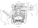
図1〜図5には、本発明に従う構造とされた防振装置の第1の実施形態として、自動車用のエンジンマウント10が示されている。エンジンマウント10は、マウント本体11を有しており、このマウント本体11が第1の取付部材12と第2の取付部材14を本体ゴム弾性体16で連結した構造を備えている。そして、第1の取付部材12がパワーユニット18に取り付けられると共に、第2の取付部材14が車両ボデー20に取り付られることにより、パワーユニット18が車両ボデー20によって防振支持されるようになっている。なお、以下の説明において、上下方向とは、原則として、エンジンマウント10の弾性主軸であって、主たる振動入力方向でもある、図1中の上下方向を言う。また、図1〜図5に示されているのは、車両に装着する前の単体状態でのエンジンマウント10であって、第1の取付部材12と第2の取付部材14の間にパワーユニット18の支持荷重が入力されていない状態となっている。
1 to 5 show an
より詳細には、第1の取付部材12は、略円形ブロック形状を有する高剛性の部材であって、鉄やアルミニウム合金等の金属材料で形成されている。また、第1の取付部材12の径方向中央には、上下方向に延びて上端面に開口する螺子孔22が形成されており、その内周面にねじ山が形成されている。更に、第1の取付部材12には、上方に向かって突出する突起部24が一体形成されている。この突起部24は、略円柱形状であって、中心軸から外周側に外れた径方向中間部分に形成されており、本実施形態では周上の1箇所に設けられている。
More specifically, the first mounting
また、第1の取付部材12の上端部には、フランジ部26が一体形成されている。フランジ部26は、第1の取付部材12の全周に亘って連続的に形成されて環状となっており、第1の取付部材12の上端外周面から外周側に向かって突出している。なお、フランジ部26の上端面を含む第1の取付部材12の上端面が、軸直角方向に広がる平坦な外側端面28とされており、エンジンマウント10の中心軸方向(本体ゴム弾性体16の弾性主軸の延出方向)における第1の取付部材12の軸方向外側の端面が外側端面28で構成されている。
In addition, a
一方、第2の取付部材14は、薄肉大径の略円筒形状とされており、第1の取付部材12と同様に高い剛性を有している。また、第2の取付部材14は、軸方向中間部分の段差を挟んだ上側が大径部30とされていると共に、段差を挟んだ下側が小径部32とされている。
On the other hand, the second mounting
そして、第1の取付部材12と第2の取付部材14は、同一中心軸上で第1の取付部材12が第2の取付部材14の上方に離隔するように配置されて、本体ゴム弾性体16によって弾性的に連結されている。
The first mounting
本体ゴム弾性体16は、厚肉大径の略円錐台形状とされており、その小径側端部に第1の取付部材12が差し込まれて加硫接着されていると共に、大径側端部の外周面に第2の取付部材14が重ね合わされて加硫接着されている。なお、本実施形態において、本体ゴム弾性体16は、第1の取付部材12と第2の取付部材14を備えた一体加硫成形品として形成されている。
The main rubber
また、本体ゴム弾性体16の大径側端面には、中央凹所34が開口している。中央凹所34は、上底側が逆向きの略すり鉢状とされて上方に向かって次第に小径となっていると共に、開口側が略一定の円形断面を有する円柱状とされている。更に、本体ゴム弾性体16における中央凹所34の開口周縁部には、薄肉大径の略円筒形状を有するシールゴム層36が一体形成されて、下方に向かって延び出しており、第2の取付部材14の小径部32の内周面を覆うように加硫接着されている。
Further, a
また、第2の取付部材14の下側開口部には、可撓性膜38が取り付けられている。可撓性膜38は、薄肉の略円板形状を有するゴム膜であって、軸方向に充分な弛みを有している。更に、可撓性膜38の外周縁部には、環状の固定金具40が加硫接着されており、可撓性膜38が固定金具40を備えた一体加硫成形品として形成されている。そして、固定金具40が第2の取付部材14の小径部32の下端に差し入れられた後、第2の取付部材14に対して八方絞りなどの縮径加工が施されることにより、可撓性膜38が第2の取付部材14に取り付けられている。
A
このような可撓性膜38の装着状態において、第2の取付部材14の内周側には、本体ゴム弾性体16と可撓性膜38の対向面間に外部から流体密に隔てられた流体封入領域42が形成されており、非圧縮性流体が封入されている。なお、流体封入領域42に封入される非圧縮性流体としては、特に限定されるものではないが、水やアルキレングリコール,ポリアルキレングリコール,シリコーン油、或いはそれらの混合液等が好適に採用される。更に、後述する流体の流動作用に基づく防振効果を効率的に発揮させるためには、0.1Pa・s以下の低粘性流体が望ましい。
In such a state where the
また、流体封入領域42には、仕切部材44が配設されている。仕切部材44は、略円板形状を有しており、仕切部材本体46と底金具48と可動ゴム膜50とを備えている。仕切部材本体46は、略円板形状を有する硬質の部材であって、径方向中央部分には、軸方向に貫通する円形の上側透孔52が形成されている。また、仕切部材本体46の外周縁部には、外周面に開口して周方向に1周弱の所定の長さで延びる周溝54が形成されている。
A
底金具48は、全体として薄肉の略円環板形状を有しており、径方向中央部分に円形の下側透孔56が形成されていると共に、径方向中間部分に設けられた段差を挟んで内周部分が外周部分よりも上方に位置している。そして、底金具48は、仕切部材本体46に対して下方から重ね合わされて固定されている。
The bottom metal fitting 48 has a thin, generally annular plate shape as a whole, a circular lower through
また、仕切部材本体46と底金具48の間には、可動ゴム膜50が配設されている。可動ゴム膜50は、略円板形状を有するゴム弾性体であって、外周部分が周方向環状に延びる略円形断面の厚肉部となっている。また、可動ゴム膜50は、径方向中央部分の両面が径方向中央側に向かって次第に軸方向外側に傾斜するテーパ面となっており、可動ゴム膜50が径方向中央に向かって次第に厚肉となっている。そして、可動ゴム膜50は、厚肉部が仕切部材本体46と底金具48の間に挟み込まれて、径方向中央部分に配設されており、仕切部材本体46の上側透孔52と底金具48の下側透孔56を閉塞するように軸直角方向で広がって配設されている。
A
このような構造とされた仕切部材44は、流体封入領域42に収容されて、第2の取付部材14によって支持されている。即ち、流体封入領域42内で軸直角方向に広がるように配設された仕切部材44は、外周面が第2の取付部材14の内周面に対してシールゴム層36を介して押し当てられることによって固定的に支持されている。
The
そして、仕切部材44が流体封入領域42内に配設されることにより、流体封入領域42は、仕切部材44を挟んで上下に二分されている。即ち、仕切部材44を挟んだ上方には、壁部の一部が本体ゴム弾性体16で構成されて、振動入力時に圧力変動が惹起される、受圧室58が形成されている一方、仕切部材44を挟んだ下方には、壁部の一部を可撓性膜38で構成されて、容積変化が容易に許容される、平衡室60が形成されている。なお、受圧室58と平衡室60には、それぞれ流体封入領域42に封入された非圧縮性流体が封入されている。
The
また、周溝54の開口部が第2の取付部材14によって覆われていると共に、周溝54の周方向両端部が受圧室58と平衡室60の各一方に連通されている。これにより、受圧室58と平衡室60を相互に連通するオリフィス通路62が、周溝54を利用して一周弱の所定長さで形成されている。なお、オリフィス通路62は、通路断面積(A)と通路長(L)の比(A/L)を調節することにより、チューニング周波数が調節されており、本実施形態では、エンジンシェイクに相当する10Hz程度の低周波数にチューニングされている。
The opening of the
また、可動ゴム膜50には、その一方の面に受圧室58の圧力が及ぼされていると共に、他方の面に平衡室60の圧力が及ぼされている。そして、アイドリング振動等に相当する中乃至高周波数の振動入力時には、受圧室58と平衡室60の相対的な圧力差に基づいて、可動ゴム膜50が共振状態で積極的に微小変形するようになっている。
Further, the pressure of the
かくの如き構造とされたマウント本体11には、インナブラケット64が取り付けられている。インナブラケット64は、厚肉の略板形状であって、マウント本体11の径方向一方向で外方(図1中、右方)に向かって延び出している。また、インナブラケット64の基端部分には、上下に貫通するボルト孔66が形成されている。更に、ボルト孔66の上側開口周縁部には、ボルト孔66よりも大径の凹所67が形成されており、インナブラケット64の上面に開口していると共に、インナブラケット64の基端側(図1中、左側)に延び出して基端面に開口している。更に、インナブラケット64の先端部分には、互いに所定距離を隔てた3つのボルト孔68,68,68がそれぞれ上下に貫通するように設けられており、もって、パワーユニット18への取付部69が形成されている。また、インナブラケット64における延出方向の基端部分には、第1の取付部材12の突起部24と対応する形状で、下面に開口する凹所状とされた挿入凹所70が設けられている。更に、インナブラケット64には、幅方向一方の面に開口する図示しない係止凹溝が軸方向上下に延びるように形成されている。
An
そして、インナブラケット64は、延出方向の基端部分が第1の取付部材12に対して上方から重ね合わされてボルト71で固定されており、側方(後述する門形部材82の幅方向一方の側)に延び出している。これにより、ボルト孔68,68,68を備えたパワーユニット18への取付部69が、インナブラケット64における第1の取付部材12から側方への延出先端部分に設けられている。また、第1の取付部材12の突起部24が挿入凹所70に挿入されることによって、インナブラケット64の第1の取付部材12に対するボルト71の中心軸周りでの回転が防止されて、インナブラケット64が第1の取付部材12に対して位置決めされている。本実施形態では、ボルト孔66に挿通されたボルト71の頭部が凹所67に収容されており、インナブラケット64上面からの突出量が抑えられている。なお、第1の取付部材12に上方に向かって突出するボルトが設けられており、該ボルトがインナブラケット64のボルト孔66に挿通されると共に、該ボルトにナットが締結されることにより、第1の取付部材12とインナブラケット64が固定されるようになっていても良い。
The
一方、マウント本体11には、アウタブラケット72が取り付けられている。このアウタブラケット72は、略円筒形状の嵌着部74を有しており、嵌着部74が第2の取付部材14に外嵌されることによって、マウント本体11に固定されている。
On the other hand, an
また、嵌着部74には、当接部76が固定されている。当接部76は、周方向に所定の長さで延びる板状とされており、その周上の複数箇所には下方に延び出す固着片78が一体形成されている。そして、固着片78が嵌着部74の上端外周面に重ね合わされて溶接などの手段で固着されることにより、当接部76が嵌着部74に対して軸直角方向で広がるように固定されている。
A
さらに、嵌着部74には、連結部80が固定されている。連結部80は、幅方向両側に設けられたリブによって補強された略板状であって、嵌着部74の周上における当接部76と径方向で対向する部分に取り付けられて、インナブラケット64と反対側に向かって延び出している。なお、連結部80は、延出方向の基端側の端部が嵌着部74の外周面に対して溶接などの手段で固着されることにより、嵌着部74に対して固定されている。
Further, the connecting
更にまた、嵌着部74には、門形部材82が固定されている。門形部材82は、略上下方向に延びて互いに対向配置された一対の脚部84,84と、それら脚部84,84の上端を相互に繋ぐ梁部86とを一体的に備えている。また、門形部材82における開口方向(図1の左右方向)の両端部には、それら脚部84,84と梁部86の略全長に亘って当接リブ88が一体形成されており、それぞれ板状とされた脚部84,84と梁部86が当接リブ88によって補強されている。そして、門形部材82は、脚部84,84の中間部分が嵌着部74の外周面に固着されていると共に、脚部84,84を補強する当接リブ88が当接部76の周方向の両端部に固着されており、それらによって嵌着部74に固定されている。
Furthermore, a gate-shaped
かくの如き構造とされたアウタブラケット72は、嵌着部74が第2の取付部材14に外嵌固定されることにより、第2の取付部材14側に取り付けられている。なお、嵌着部74は、上端部が内周側に向かって屈曲しており、かかる屈曲部分が第2の取付部材14の上端面に当接することで、嵌着部74が第2の取付部材14に対して位置決めされて、アウタブラケット72がマウント本体11に対する適正な位置に装着されるようになっている。
The
このようなアウタブラケット72の第2の取付部材14への装着状態において、アウタブラケット72の当接部76がインナブラケット64に対して上下方向で所定距離を隔てて対向している。そして、それらインナブラケット64と当接部76が当接することにより、第1の取付部材12と第2の取付部材14の軸方向上下での相対的な接近変位量が制限されるようになっている。これにより、インナブラケット64と当接部76の対向部分を利用して、パワーユニット18の車両ボデー20に対する下方への相対変位量を制限するバウンドストッパ機構が構成されている。
In such a state that the
また、アウタブラケット72の門形部材82は、インナブラケット64を跨ぐように配設されており、インナブラケット64が門形部材82の幅方向一方の開口を通じて幅方向一方の側(図1中、右側)に延び出している。そして、インナブラケット64の一部と門形部材82の梁部86の一部とが上下に対向しており、それらインナブラケット64と門形部材82が当接することにより、第1の取付部材12と第2の取付部材14の軸方向上下での離隔変位量が制限されるようになっている。これにより、インナブラケット64と門形部材82の対向部分を利用して、パワーユニット18の車両ボデー20に対する上方への相対変位量を制限するリバウンドストッパ機構が構成されている。
Further, the gate-shaped
さらに、インナブラケット64は、門形部材82の一対の脚部84,84に対して車両前後方向(図2中、左右方向)で対向している。そして、それらインナブラケット64と脚部84が当接することにより、第1の取付部材12と第2の取付部材14の車両前後方向への相対変位量が制限されるようになっている。これにより、インナブラケット64と一対の脚部84,84との対向部分を利用して、パワーユニット18の車両ボデー20に対する車両前後方向での相対変位量を制限する前後方向ストッパ機構が構成されている。
Furthermore, the
これらの各ストッパ機構で第1の取付部材12と第2の取付部材14の相対変位量が制限されていることにより、衝撃的な振動の入力時に本体ゴム弾性体16が過大に変形させられるのを防いで、耐久性の低下を防止することができる。
Since the relative displacement amounts of the first mounting
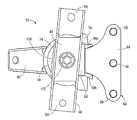
また、マウント本体11に装着されたインナブラケット64とアウタブラケット72の間には、ストッパゴム90が配設されている。本実施形態のストッパゴム90は、図6〜図11に示されているように、全体として略袋状とされており、図1,図2に示されているように、インナブラケット64に被せ付けられることによって、インナブラケット64と門形部材82の間に配設されている。
A
より詳細には、ストッパゴム90は、インナブラケット64の基端側の端面および両側面に重ね合わされる周壁部92と、周壁部92の上側開口を覆うように設けられた上壁部94と、周壁部92の下側開口の一部を覆うように設けられた下壁部96とを、有している。
More specifically, the
周壁部92は、それぞれが略板形状とされた3つの側壁部98a,98b,98cによって構成されており、側壁部98bと側壁部98cが側壁部98aの幅方向(図9中、上下方向)の両端部からインナブラケット64の延出方向(図9中、右方)に向かって延び出すように一体形成された構造を有している。そして、側壁部98aがインナブラケット64の基端側の端面に重ね合わされていると共に、互いに対向する側壁部98bと側壁部98cがインナブラケット64の幅方向両側面に重ね合わされている。
The
また、側壁部98aには幅方向の中間部分に上下に延びる凹溝99が設けられており、インナブラケット64に対して重ね合わされる内面に開口している。また、側壁部98bには延出方向の中間部分に上下に延びる係止突起100が設けられており、側壁部98cとの対向方向の内側に向かって突出している。更に、側壁部98b,98cの側壁部98aと反対側の端面が傾斜面となっており、側壁部98b,98cの下端がインナブラケット64の延出方向で上端よりも大きく延び出している。
Further, the
上壁部94は、図8,図11に示されているように、板状とされており、周壁部92と一体形成されて、周壁部92の上側開口を覆うように設けられている。そして、上壁部94は、インナブラケット64の基端部分の上面に重ね合わされて、インナブラケット64と門形部材82の梁部86との間に配設されている。なお、上壁部94には、上下に貫通する円形の挿通孔102が設けられており、ストッパゴム90の装着後に挿通孔102を通じて第1の取付部材12とインナブラケット64をボルト71で締結できるようになっている。
As shown in FIGS. 8 and 11, the
下壁部96は、図9,図11に示されているように、上壁部94と略平行に広がる板状となっており、周壁部92と一体形成されて、下方に向かって開放された周壁部92の下側開口の一部を覆っている。また、下壁部96は、周壁部92における側壁部98b,98cの延出方向の先端部分(図9中、左端部分)に一体形成されており、第1の取付部材12とインナブラケット64の重ね合わせ部分を側壁部98aと反対側に外れた位置において側壁部98bと側壁部98cを繋ぐように一体形成されている。これにより、周壁部92の下端と下壁部96とで囲まれた領域が、下方に向かって開口する開口窓104とされている。
As shown in FIGS. 9 and 11, the
そして、ストッパゴム90は、インナブラケット64に対して基端側から先端側に向かって外挿されて、非接着で被せ付けられる。これにより、周壁部92がインナブラケット64の基端部分の外周面を覆うように重ね合わされており、ストッパゴム90がインナブラケット64の外周面上に間で突出して設けられている。また、ストッパゴム90の側壁部98bに設けられた係止突起100が、インナブラケット64の側面に設けられた図示しない係止凹溝に挿し入れられることにより、ストッパゴム90がインナブラケット64に対して位置決めされている。また、ストッパゴム90のインナブラケット64への装着状態において、側壁部98aは、インナブラケット64の基端側の端面(図1中、左端面)に対して、凹溝99の形成部分で図1に示されているように離隔していると共に、凹溝99を外れた両側(図1の紙面直交方向の両側)で重ね合わされて当接している。なお、ストッパゴム90の装着方向とは、上述の如くインナブラケット64の基端側から先端側に向かう方向であって、図1中における右方向をいう。
The
かかるストッパゴム90のインナブラケット64への装着後、インナブラケット64が第1の取付部材12に対して開口窓104を通じて重ね合わされてボルト71で固定される。なお、インナブラケット64の基端面に開口する凹所67が、インナブラケット64の第1の取付部材12への装着状態において、ストッパゴム90の凹溝99に連通されており、もって、排水路が形成されている。そして、開口窓104を通じてインナブラケット64とストッパゴム90の間に入り込んだ雨水等が、排水路を通じて速やかに外部に排出されるようになっている。
After the
また、ストッパゴム90の上壁部94がインナブラケット64と門形部材82の梁部86との間に、下壁部96がインナブラケット64と当接部76との間に、側壁部98b,98cがインナブラケット64と門形部材82の脚部84,84との間に、それぞれ配設される。これらによって、インナブラケット64とアウタブラケット72がストッパゴム90を介して緩衝的に当接するようになっており、バウンドストッパ機構と、リバウンドストッパ機構と、前後方向ストッパ機構の、それぞれに対して、緩衝ゴムがストッパゴム90によって与えられている。なお、ストッパゴム90の下壁部96は、インナブラケット64の第1の取付部材12への重ね合わせ部分よりも先端側において下面に重ね合わされており、側壁部98a側に位置する端面が、第1の取付部材12の外周面と対向して、インナブラケット64の延出方向で所定の距離を隔てて配置されている。
Further, the
また、エンジンマウント10の単体状態(車両への非装着状態)において、ストッパゴム90の上壁部94は、インナブラケット64と門形部材82の間で挟圧されて、上下方向で圧縮されている。これにより、インナブラケット64と門形部材82は、ストッパゴム90を介して間接的に押し当てられており、ストッパゴム90と門形部材82の間に摩擦力が作用している。更に、インナブラケット64がストッパゴム90を介して門形部材82に当接されることにより、本体ゴム弾性体16に軸方向の予圧縮が及ぼされて、単体の自由形状に比して軸方向で圧縮変形されている。
Further, when the
そして、ストッパゴム90には、インナブラケット64と門形部材82を相対的に所定の方向で位置決めするために、弾性当接突部106が一体形成されている。弾性当接突部106は、ストッパゴム90における上壁部94の側壁部98a側の端縁部から上方に向かって突出する突条であって、門形部材82の幅方向端縁部に沿って連続する直線的な形状とされている。また、弾性当接突部106は、インナブラケット64の延出側(図11中、左側)の側面が凹状に湾曲する傾斜面とされて、門形部材82の幅方向端面に略対応する形状とされており、突出先端側に向かって次第に狭幅となっている。また、ストッパゴム90のインナブラケット64への装着状態において、弾性当接突部106は、門形部材82を幅方向他方の側に外れた位置で門形部材82に向かって突出するように設けられている。
An
また、弾性当接突部106は、ストッパゴム90におけるインナブラケット64の外周面上に突出した部分に形成されており、インナブラケット64を外れた位置に設けられて、荷重入力方向であるインナブラケット64と門形部材82の対向方向に突設されている。更に、弾性当接突部106は、ストッパゴム90における側壁部98a側の端部に設けられており、インナブラケット64における取付部69の延出方向と反対側(図1中、左側)に突設されている。なお、弾性当接突部106がインナブラケット64を外れた位置に設けられるとは、インナブラケット64と門形部材82が対向する方向(軸方向)での投影において、弾性当接突部106とインナブラケット64が重なることなく配置されていることである。
Further, the
このストッパゴム90の弾性当接突部106は、エンジンマウント10の車両装着前の単品状態において、全長に亘って門形部材82の幅方向他方の端縁部に対して側方から当接して重ね合わされている。これにより、ストッパゴム90を装着されたインナブラケット64が、弾性当接突部106の門形部材82に対する係止作用を利用して、門形部材82に対して所定の向きに位置決めされている。
The
特に本実施形態では、弾性当接突部106が門形部材82に沿って連続的に延びる突条とされており、インナブラケット64の周方向への揺動変位に対して、揺動中心から離れたところにおいて、弾性当接突部106と門形部材82の当接による係止作用が発揮される。それ故、インナブラケット64の門形部材82に対する相対回転がより効果的に防止されて、それらインナブラケット64と門形部材82が有効に位置決めされている。
In particular, in the present embodiment, the
加えて、弾性当接突部106が連続して延びる突条とされていることによって、弾性当接突部106と門形部材82の幅方向端縁部の当接面積が大きく確保されており、インナブラケット64と門形部材82の間に有効な位置決め作用が及ぼされている。
In addition, since the
また、弾性当接突部106が門形部材82の幅方向端縁部に沿って延びるように、目視しながらインナブラケット64と門形部材82の相対位置を調節することにより、ずれているインナブラケット64と門形部材82を正しい位置に容易に戻すことも可能とされる。
Further, by adjusting the relative position of the
このように、エンジンマウント10では、インナブラケット64と門形部材82が相対的に正しい向きで保持される。更に、インナブラケット64の取付部69の延出方向と、アウタブラケット72の連結部80の延出方向が、相対的に正しい向きに設定されることによって、車両への装着不良等も回避される。
Thus, in the
また、門形部材82側には、位置決めのために貫通孔等の特別な構造を設ける必要がなく、リバウンドストッパ機構においてインナブラケット64と門形部材82の梁部86との当接面積を効率的に大きく確保することができる。それ故、リバウンドストッパ機構において、門形部材82の幅方向寸法を大きくすることなく、目的とする変位規制作用を得ることができて、有効なリバウンドストッパ機構を有するエンジンマウント10が軽量且つコンパクトに実現される。
Further, it is not necessary to provide a special structure such as a through-hole for positioning on the gate-shaped
また、ストッパゴム90は袋状とされていることによって形状の安定性が高められており、インナブラケット64を外れた位置に設けられた弾性当接突部106が、周壁部92によって所定の位置に安定して保持されている。それ故、車両装着前の単品状態において、弾性当接突部106の門形部材82への当接による位置決め作用が有効に発揮されて、インナブラケット64とアウタブラケット72の相対的な位置ずれが防止される。
Further, the
また、弾性当接突部106は、突出高さ寸法に対して幅寸法が大きくされており、門形部材82の幅方向端縁部との当接によって及ぼされる当接圧に対して、充分な形状安定性が確保されている。しかも、弾性当接突部106は、突出方向の基端側(下側)に向かって次第に幅寸法が大きくなっており、当接圧に対する形状安定性が更に高められている。それ故、弾性当接突部106と門形部材82の当接によるインナブラケット64とアウタブラケット72の相対的な位置決め作用が有効に発揮される。
Further, the
なお、エンジンマウント10は、図1に示されているように、インナブラケット64の先端側がパワーユニット18に対して取り付けられるようになっていると共に、アウタブラケット72の連結部80が車両ボデー20に対して取り付けられるようになっている。
As shown in FIG. 1, the
そして、エンジンマウント10が車両に装着されることにより、パワーユニット18の支持荷重が第1の取付部材12と第2の取付部材14の間に入力されて、第1の取付部材12と第2の取付部材14が軸方向で相対的に接近変位する。これにより、インナブラケット64とストッパゴム90は、門形部材82の梁部86と当接部76との中間で、それらの何れからも離隔した位置(本実施形態では略中央)に変位する。更に、ストッパゴム90の弾性当接突部106は、図12の(a)に示されている門形部材82の梁部86の幅方向端面に対する当接状態が、図12の(b)に示されているように解除されて、梁部86に対して下方に離隔して配置されている。
When the
このような車両への装着状態において、第1の取付部材12と第2の取付部材14の間にエンジンシェイクに相当する低周波数の振動が入力されると、受圧室58と平衡室60の相対的な圧力変動によって、オリフィス通路62を通じて両室58,60間での流体流動が生ぜしめられる。これにより、流体の共振作用等の流動作用に基づいて、目的とする防振効果(高減衰効果)が発揮されるようになっている。
When a low-frequency vibration corresponding to an engine shake is input between the first mounting
一方、アイドリング振動に相当する中乃至高周波数の振動入力時には、可動ゴム膜50が共振状態で積極的に微小変形することにより、目的とする防振効果(低動ばね効果)が発揮されるようになっている。
On the other hand, at the time of vibration input of medium to high frequency corresponding to idling vibration, the
また、弾性当接突部106がインナブラケット64を外れて設けられていることにより、衝撃的な大振幅振動の入力によって弾性当接突部106が門形部材82に打ち当てられる場合に、弾性当接突部106がインナブラケット64と門形部材82の間で挟み込まれるのを回避することができる。それ故、弾性当接突部106と門形部材82の当接による衝撃力が低減されて、振動や打音の発生を抑えることができる。
Further, since the
さらに、ストッパゴム90がゴム弾性体の単体で形成されていることから、弾性当接突部106の周壁部92による所定位置への保持が、弾性的に実現されている。それ故、車両への装着状態において、弾性当接突部106が門形部材82に打ち当たる際には、周壁部92の変形により弾性当接突部106の変位が充分に許容されて、当接時の衝撃が緩和される。従って、車両装着前の単品状態において有効な位置決め作用が発揮されると共に、車両装着時には弾性当接突部106の門形部材82への当接による振動や打音の発生が抑制される。
Further, since the
以上、本発明の実施形態について詳述してきたが、本発明はその具体的な記載によって限定されない。例えば、前記実施形態では、袋状のストッパゴム90がインナブラケット64の基端部分に非接着で被せられた構造が示されているが、ストッパゴムは、例えば、インナブラケット64の基端部分に接着等によって固着されていても良い。具体的には、例えば、インナブラケット64の基端部分の上面に板状のストッパゴムが重ね合わされて、接着剤や加硫接着等の手段でインナブラケット64に固定された構造等も採用され得る。
As mentioned above, although embodiment of this invention was explained in full detail, this invention is not limited by the specific description. For example, in the above-described embodiment, a structure in which the bag-
また、ストッパゴム90には、門形部材82の幅方向端縁部に沿って連続的に延びる突条とされた弾性当接突部106が設けられているが、弾性当接突部は、必ずしも実施形態に示された構造に限定されるものではない。具体的には、例えば、弾性当接突部は、1つ乃至は複数の突起として設けられていても良く、その突起が門形部材82の幅方向端縁部に沿ってある程度の長さで延びていても良い。なお、このような比較的に長さの短い弾性当接突部が形成される場合には、位置決め作用を効果的に得るために、少なくとも2つの弾性当接突部が長さ方向(門形部材82の梁部86が延びる方向)にできるだけ大きく離隔して設けられていることが望ましい。
Further, the
また、弾性当接突部は、ストッパゴムにおけるインナブラケット64の延出側(図1の右側)に形成されて、門形部材82の他方の幅方向端縁部に側方から当接していても良い。更に、ストッパゴムの両端部に弾性当接突部が形成されて、それら弾性当接突部が門形部材82に対して幅方向で挟み込むように当接して重ね合わされることにより、位置決め作用をより効果的に得ることも可能である。
Further, the elastic contact protrusion is formed on the extending side (the right side in FIG. 1) of the
また、マウント本体の構造は、特に限定されるものではなく、ブロック状の本体ゴム弾性体に第1の取付部材と第2の取付部材を取り付けて、本体ゴム弾性体の内部摩擦等に基づいた防振効果を利用する、流体封入式以外の防振装置であっても良いし、流体封入式防振装置においてアクチュエータの能動的な加振力によって防振性能の更なる向上を図った能動型の流体封入式防振装置であっても良い。 The structure of the mount body is not particularly limited, and the first attachment member and the second attachment member are attached to the block-like body rubber elastic body, and the structure is based on the internal friction of the body rubber elastic body. An anti-vibration device other than the fluid-sealed type that utilizes the anti-vibration effect may be used, or an active type that further improves the vibration-proof performance by the active excitation force of the actuator in the fluid-filled type anti-vibration device A fluid-filled vibration isolator may be used.
また、前記実施形態の防振装置(エンジンマウント10)では、車両装着前の単体状態において、インナブラケット64と門形部材82がストッパゴム90を挟み込んで間接的に当接しており、本体ゴム弾性体16に軸方向の予圧縮が及ぼされていた。しかし、防振装置は、例えば、車両装着前の単体状態において、インナブラケット64に設けられたストッパゴム90の上面が門形部材82から下方に離隔している構造であっても良い。このような構造において、弾性当接突部106が門形部材82の幅方向端縁部に当接している本発明の構造を適用すれば、第1の取付部材12から側方へ大きく突出したインナブラケット64の取付部69が下方に変位するのを、弾性当接突部106と門形部材82の当接係止によって抑えることができる。その結果、エンジンマウント10の車両への組付け時に、インナブラケット64のパワーユニット18への組付け位置(パワーユニット18に対する取付部69の相対位置)が大きくずれるのを防ぐことができて、パワーユニット18への組付け作業を容易に実施することが可能となる。
Further, in the vibration isolator (engine mount 10) of the above-described embodiment, the
また、本発明の防振装置は、エンジンマウントとしてのみ利用されるものではなく、サブフレームマウントやデフマウント等としても採用され得る。また、本発明は、自動車用の防振装置だけでなく、自動二輪車,鉄道用車両,産業用車両等の各種車両用の防振装置や、その他各種の振動源と防振対象部材を連結する防振装置にも、好適に適用される。 The vibration isolator of the present invention is not only used as an engine mount, but can also be used as a subframe mount, a differential mount, or the like. Further, the present invention connects not only a vibration isolator for automobiles but also a vibration isolator for various vehicles such as a motorcycle, a railway vehicle, an industrial vehicle, and other various vibration sources to a vibration isolation target member. The present invention is also preferably applied to a vibration isolator.
10:エンジンマウント(防振装置)、12:第1の取付部材、14:第2の取付部材、16:本体ゴム弾性体、28:外側端面、64:インナブラケット、69:取付部、82:門形部材、90:ストッパゴム、106:弾性当接突部 10: engine mount (vibration isolation device), 12: first mounting member, 14: second mounting member, 16: main rubber elastic body, 28: outer end face, 64: inner bracket, 69: mounting portion, 82: Gate-shaped member, 90: stopper rubber, 106: elastic contact protrusion
Claims (5)
前記インナブラケットには、前記門形部材を幅方向に外れた位置で該門形部材側に向かって突出する弾性当接突部が、前記ストッパゴムと一体形成されており、前記支持荷重が入力されていない状態で該弾性当接突部が該門形部材の幅方向端縁部に対して側方から当接して重ね合わされていることを特徴とする防振装置。 The first mounting member and the second mounting member are connected by a main rubber elastic body, and an inner bracket is overlapped and fixed to the outer end surface of the first mounting member. A gate-shaped member extending over the inner bracket is attached to the second mounting member while extending laterally from the first mounting member, and is rebounded at a portion facing the inner bracket and the portal-shaped member. A stopper mechanism is configured, and a stopper rubber is provided on a surface of the inner bracket facing the gate-shaped member, so that the first mounting member and the second mounting member approach each other. In the anti-vibration device to which the supporting load is applied ,
The inner bracket is integrally formed with the stopper rubber, and an elastic contact protrusion that protrudes toward the portal member at a position where the portal member is removed in the width direction, and the support load is input to the inner bracket. The anti-vibration device according to claim 1, wherein the elastic contact protrusions are in contact with each other against the widthwise end edge of the gate-shaped member in a state where the elastic contact protrusions are not applied.
Priority Applications (1)
| Application Number | Priority Date | Filing Date | Title |
|---|---|---|---|
| JP2010249433A JP5654843B2 (en) | 2010-11-08 | 2010-11-08 | Vibration isolator |
Applications Claiming Priority (1)
| Application Number | Priority Date | Filing Date | Title |
|---|---|---|---|
| JP2010249433A JP5654843B2 (en) | 2010-11-08 | 2010-11-08 | Vibration isolator |
Publications (2)
| Publication Number | Publication Date |
|---|---|
| JP2012102761A JP2012102761A (en) | 2012-05-31 |
| JP5654843B2 true JP5654843B2 (en) | 2015-01-14 |
Family
ID=46393401
Family Applications (1)
| Application Number | Title | Priority Date | Filing Date |
|---|---|---|---|
| JP2010249433A Active JP5654843B2 (en) | 2010-11-08 | 2010-11-08 | Vibration isolator |
Country Status (1)
| Country | Link |
|---|---|
| JP (1) | JP5654843B2 (en) |
Families Citing this family (5)
| Publication number | Priority date | Publication date | Assignee | Title |
|---|---|---|---|---|
| JP6207320B2 (en) * | 2013-09-25 | 2017-10-04 | 住友理工株式会社 | Vibration isolator |
| JP6297400B2 (en) * | 2014-04-30 | 2018-03-20 | 住友理工株式会社 | Vibration isolator |
| JP6456340B2 (en) * | 2016-11-17 | 2019-01-23 | 東洋ゴム工業株式会社 | Vibration isolator |
| JP6456341B2 (en) * | 2016-11-17 | 2019-01-23 | 東洋ゴム工業株式会社 | Vibration isolator |
| JP6456339B2 (en) | 2016-11-17 | 2019-01-23 | 東洋ゴム工業株式会社 | Vibration isolator |
Family Cites Families (6)
| Publication number | Priority date | Publication date | Assignee | Title |
|---|---|---|---|---|
| JPH0425052U (en) * | 1990-06-26 | 1992-02-28 | ||
| JP2000266122A (en) * | 1999-03-15 | 2000-09-26 | Toyoda Gosei Co Ltd | Vibration control mount |
| JP2006161973A (en) * | 2004-12-08 | 2006-06-22 | Tokai Rubber Ind Ltd | Engine mount |
| JP2008144899A (en) * | 2006-12-12 | 2008-06-26 | Bridgestone Corp | Vibration isolating system |
| JP2008248951A (en) * | 2007-03-29 | 2008-10-16 | Tokai Rubber Ind Ltd | Vibration control device |
| JP5150443B2 (en) * | 2008-10-02 | 2013-02-20 | 株式会社ブリヂストン | Vibration isolator |
-
2010
- 2010-11-08 JP JP2010249433A patent/JP5654843B2/en active Active
Also Published As
| Publication number | Publication date |
|---|---|
| JP2012102761A (en) | 2012-05-31 |
Similar Documents
| Publication | Publication Date | Title |
|---|---|---|
| US7275738B2 (en) | Cylindrical fluid-filled vibration damping device | |
| JP4359889B2 (en) | Fluid filled vibration isolator | |
| JP4171219B2 (en) | Vibration control device | |
| JP4348553B2 (en) | Fluid-filled vibration isolator and manufacturing method thereof | |
| JP4529142B2 (en) | Vibration isolator | |
| JP4196401B2 (en) | Fluid filled cylindrical vibration isolator | |
| WO2015145672A1 (en) | Anti-vibration device | |
| JP2005023973A (en) | Vibration damper with stopper mechanism | |
| JP5654843B2 (en) | Vibration isolator | |
| JP6275493B2 (en) | Vibration isolator with bracket | |
| JP4945162B2 (en) | Vibration isolator | |
| JP5449052B2 (en) | Vibration isolator | |
| JP2007177991A (en) | Vibration damping device | |
| JP5829156B2 (en) | Vibration isolator | |
| JP5695851B2 (en) | Torque rod and engine unit | |
| JP5060846B2 (en) | Fluid filled vibration isolator | |
| JP4340911B2 (en) | Vibration isolator | |
| JP4959390B2 (en) | Fluid filled vibration isolator | |
| JP2018001797A (en) | Strut mount and suspension mechanism using the same | |
| JP5512403B2 (en) | Vibration isolator and vibration isolator bracket | |
| JP4081421B2 (en) | Anti-vibration mount assembly | |
| JP5738062B2 (en) | Fluid filled vibration isolator | |
| JP4533606B2 (en) | Anti-vibration mounting device | |
| JP5386289B2 (en) | Fluid filled vibration isolator | |
| JP2006300314A (en) | Fluid-filled cylindrical vibration damper |
Legal Events
| Date | Code | Title | Description |
|---|---|---|---|
| A621 | Written request for application examination |
Free format text: JAPANESE INTERMEDIATE CODE: A621 Effective date: 20130805 |
|
| A977 | Report on retrieval |
Free format text: JAPANESE INTERMEDIATE CODE: A971007 Effective date: 20140313 |
|
| A131 | Notification of reasons for refusal |
Free format text: JAPANESE INTERMEDIATE CODE: A131 Effective date: 20140423 |
|
| A521 | Written amendment |
Free format text: JAPANESE INTERMEDIATE CODE: A523 Effective date: 20140606 |
|
| TRDD | Decision of grant or rejection written | ||
| A01 | Written decision to grant a patent or to grant a registration (utility model) |
Free format text: JAPANESE INTERMEDIATE CODE: A01 Effective date: 20141110 |
|
| A61 | First payment of annual fees (during grant procedure) |
Free format text: JAPANESE INTERMEDIATE CODE: A61 Effective date: 20141121 |
|
| R150 | Certificate of patent or registration of utility model |
Ref document number: 5654843 Country of ref document: JP Free format text: JAPANESE INTERMEDIATE CODE: R150 |