JP6502973B2 - Dynamic damper mounting structure - Google Patents
Dynamic damper mounting structure Download PDFInfo
- Publication number
- JP6502973B2 JP6502973B2 JP2017007647A JP2017007647A JP6502973B2 JP 6502973 B2 JP6502973 B2 JP 6502973B2 JP 2017007647 A JP2017007647 A JP 2017007647A JP 2017007647 A JP2017007647 A JP 2017007647A JP 6502973 B2 JP6502973 B2 JP 6502973B2
- Authority
- JP
- Japan
- Prior art keywords
- dynamic damper
- bracket
- vibration
- body frame
- vehicle
- Prior art date
- Legal status (The legal status is an assumption and is not a legal conclusion. Google has not performed a legal analysis and makes no representation as to the accuracy of the status listed.)
- Active
Links
Images


Classifications
-
- B—PERFORMING OPERATIONS; TRANSPORTING
- B60—VEHICLES IN GENERAL
- B60K—ARRANGEMENT OR MOUNTING OF PROPULSION UNITS OR OF TRANSMISSIONS IN VEHICLES; ARRANGEMENT OR MOUNTING OF PLURAL DIVERSE PRIME-MOVERS IN VEHICLES; AUXILIARY DRIVES FOR VEHICLES; INSTRUMENTATION OR DASHBOARDS FOR VEHICLES; ARRANGEMENTS IN CONNECTION WITH COOLING, AIR INTAKE, GAS EXHAUST OR FUEL SUPPLY OF PROPULSION UNITS IN VEHICLES
- B60K5/00—Arrangement or mounting of internal-combustion or jet-propulsion units
- B60K5/12—Arrangement of engine supports
- B60K5/1208—Resilient supports
- B60K5/1216—Resilient supports characterised by the location of the supports relative to the motor or to each other
-
- F—MECHANICAL ENGINEERING; LIGHTING; HEATING; WEAPONS; BLASTING
- F16—ENGINEERING ELEMENTS AND UNITS; GENERAL MEASURES FOR PRODUCING AND MAINTAINING EFFECTIVE FUNCTIONING OF MACHINES OR INSTALLATIONS; THERMAL INSULATION IN GENERAL
- F16F—SPRINGS; SHOCK-ABSORBERS; MEANS FOR DAMPING VIBRATION
- F16F7/00—Vibration-dampers; Shock-absorbers
- F16F7/10—Vibration-dampers; Shock-absorbers using inertia effect
- F16F7/104—Vibration-dampers; Shock-absorbers using inertia effect the inertia member being resiliently mounted
- F16F7/108—Vibration-dampers; Shock-absorbers using inertia effect the inertia member being resiliently mounted on plastics springs
-
- F—MECHANICAL ENGINEERING; LIGHTING; HEATING; WEAPONS; BLASTING
- F16—ENGINEERING ELEMENTS AND UNITS; GENERAL MEASURES FOR PRODUCING AND MAINTAINING EFFECTIVE FUNCTIONING OF MACHINES OR INSTALLATIONS; THERMAL INSULATION IN GENERAL
- F16F—SPRINGS; SHOCK-ABSORBERS; MEANS FOR DAMPING VIBRATION
- F16F2230/00—Purpose; Design features
- F16F2230/0005—Attachment, e.g. to facilitate mounting onto confer adjustability
Description
本発明は、車両の車体フレームに対し、ダイナミックダンパブラケットを介してダイナミックダンパを連結するダイナミックダンパの取付構造に関する。 The present invention relates to a mounting structure of a dynamic damper that connects a dynamic damper via a dynamic damper bracket to a vehicle body frame of a vehicle.
例えば、特許文献1には、ダイナミックダンパを、エンジンマウントの横側の一方に延出する方向にボルトで締結したダイナミックダンパの取付構造が開示されている。特許文献1に開示された取付構造では、さらに、このボルトを介して、ダイナミックダンパを車体側ブラケットと共締めしている。
For example,
しかしながら、特許文献1に開示されたダイナミックダンパの取付構造では、エンジンマウントの横側の一方にのみダイナミックダンパが配置されることで、サブフレームを平面視して左右非対称に構成されている。このため、エンジン側から入力される振動によって、ダイナミックダンパが不安定な振動を発生させるおそれがある。
However, in the mounting structure of the dynamic damper disclosed in
また、特許文献1に開示されたダイナミックダンパの取付構造では、エンジンマウント、ダイナミックダンパ、及び、車体側ブラケットをそれぞれ共締めしているボルトが、エンジン側からの振動の入力方向と直交する方向で締結されている。このため、ボルトの軸方向と直交する方向から過大な力(振動)が入力されるおそれがある。
Further, in the mounting structure of the dynamic damper disclosed in
本発明は、前記の点に鑑みてなされたものであり、車体フレームに対し、ダイナミックダンパを安定して配置することが可能なダイナミックダンパの取付構造を提供することを目的とする。 The present invention is made in view of the above-mentioned point, and an object of the present invention is to provide a mounting structure of a dynamic damper which can arrange a dynamic damper stably to a vehicle body frame.
前記の目的を達成するために、本発明は、車両の車体フレームに対してダイナミックダンパを取り付けるための取付構造であって、前記車体フレームに対して前記ダイナミックダンパを連結するダイナミックダンパブラケットと、前記車体フレームに対してリジットに固定されるカラー部材と、前記車体フレーム上にマウントされ、弾性ブッシュを介して前記カラー部材に弾性的に連結されるマウントブラケットと、前記車体フレームに対し、前記ダイナミックダンパブラケット及び前記カラー部材をリジットに固定する固定部材と、を備え、前記固定部材は、筒状の前記カラー部材を挿通するボルトからなり、前記ダイナミックダンパブラケットと前記カラー部材とは、前記車体フレームに対し、前記カラー部材を挿通する前記ボルトによって共締めされることを特徴とする。 In order to achieve the above object, the present invention is an attachment structure for attaching a dynamic damper to a vehicle body frame of a vehicle, the dynamic damper bracket coupling the dynamic damper to the vehicle body frame, and A collar member fixed to a vehicle body frame in a rigid manner, a mount bracket mounted on the vehicle body frame and elastically coupled to the collar member via an elastic bush, and the dynamic damper for the vehicle body frame A bracket and a fixing member for fixing the collar member to the rigid body , the fixing member comprising a bolt for inserting the cylindrical collar member, and the dynamic damper bracket and the collar member are mounted on the vehicle body frame Against the bolt through which the collar member is inserted Is fastened Te characterized Rukoto.
本発明では、車体フレームに対し、ダイナミックダンパを安定して配置することが可能なダイナミックダンパの取付構造を得ることができる。 According to the present invention, it is possible to obtain a dynamic damper mounting structure capable of stably arranging the dynamic damper on the vehicle body frame.
次に、本発明の実施形態について、適宜図面を参照しながら詳細に説明する。図1は、本発明の実施形態に係るダイナミックダンパの取付構造が適用されたサブフレームの平面図である。なお、各図中において、「前後」は、車両前後方向、「左右」は、車両左右方向(車幅方向)、「上下」は、鉛直上下方向をそれぞれ示している。 Next, embodiments of the present invention will be described in detail with reference to the drawings as appropriate. FIG. 1 is a plan view of a sub-frame to which a dynamic damper mounting structure according to an embodiment of the present invention is applied. In each of the drawings, "front and rear" indicates the vehicle longitudinal direction, "left and right" indicates the vehicle lateral direction (vehicle width direction), and "upper and lower" indicate the vertical direction.
図1に示されるように、車両の車体前部側には、サブフレーム(車体フレーム)12が搭載されている。このサブフレーム12は、前部クロスメンバ14と、後部クロスメンバ16とから構成されている。前部クロスメンバ14の車幅方向に沿った両側部には、車両後方に向かって延在する前側左右サイド部18、18がそれぞれ対向配置されている。後部クロスメンバ16の車幅方向に沿った両側部には、車両前方に向かって延在して前側左右サイド部18、18と連結される後側左右サイド部20、20が設けられている。
As shown in FIG. 1, a sub-frame (vehicle body frame) 12 is mounted on the vehicle body front side of the vehicle. The
なお、本実施形態では、サブフレーム12として、前側左右サイド部18、18及び後側左右サイド部20、20を、それぞれ、前部クロスメンバ14及び後部クロスメンバ16と一体的に構成した場合を例示しているが、これに限定されるものではない。例えば、前側左サイド部18と後側左サイド部20とを一体成形して左サイドメンバ(図示せず)を構成すると共に、前側右サイド部18と後側右サイド部20とを一体成形して右サイドメンバ(図示せず)を構成するようにしてもよい。
In the present embodiment, as the
前部クロスメンバ14は、車両の車幅方向に沿って延在しパワーユニットPの前側に配置されている。後部クロスメンバ16は、車両の車幅方向に沿って延在し、パワーユニットPの後側に配置されている。前側左サイド部18及び後側左サイド部20は、平面視して車両の前後方向に沿って延在し、パワーユニットPの左側に配置されている。前側右サイド部18及び後ろ側右サイド部20は、平面視して車両の前後方向に沿って延在し、パワーユニットPの右側に配置されている。
The
サブフレーム12は、前部クロスメンバ14、後部クロスメンバ16の前側及び後側左右サイド部18、18、20、20同士を、例えば、溶接等によって一体的に固定することで、平面視して略井桁構造を呈している。なお、サブフレーム12は、略井桁構造に限定されるものではなく、例えば、左右サイドメンバに対して単一のクロスメンバで構成される場合であってもよい。
The
パワーユニットPは、例えば、エンジンE(動力源、振動発生源)及びトランスミッションが一体的に構成されたユニットからなり、サブフレーム12によってフローティング支持されている。サブフレーム12には、エンジンEをフローティング支持するフローティング機構が配置されている。このフローティング機構は、前部クロスメンバ14に配置されるフロントマウント22と、後部クロスメンバ16の後側左サイド部20に配置されるサイドマウント24と、後部クロスメンバ16に配置されるリヤマウント26とから構成されている。エンジンEは、フロントマウント22、サイドマウント24、及び、リヤマウント26からなる3点でフローティング支持されている。
The power unit P is, for example, a unit in which an engine E (power source, vibration source) and a transmission are integrally configured, and is floatingly supported by the
フロントマウント22には、取付金具28を介してエンジンEの車両前側を支持する防振装置100aが配置されている。この防振装置100aは、複数のボルト30及びフロントマウントブラケット32を介して、前部クロスメンバ14のフロントビームに対してリジットに固定されている。リヤマウント26には、取付金具34を介してエンジンEの車両後側を支持する防振装置100bが配置されている。この防振装置100bは、複数のボルト36及びマウントブラケット38を介して、後部クロスメンバ16に対してフローティング支持されている。サイドマウント24には、取付金具40を介してエンジンEの車幅方向左側を支持する他の防振装置100cが配置されている。他の防振装置100cは、複数のボルトを介して後部クロスメンバ16の後側左サイド部20にリジットに固定されている。
The
フロント側の防振装置100aとリヤ側の防振装置100bとは、それぞれ略同一構成からなる。この防振装置の構成については、後記で詳細に説明する。
The front-side
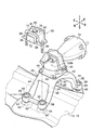
図2は、マウントブラケットに支持された防振装置及びダイナミックダンパの拡大斜視図、図3は、図2のIII−III線に沿った断面図、図4は、図2に示すダイナミックダンパの分解斜視図、図5は、本実施形態において、カラー部材を挿通するボルトによって共締めされた構造を示す車両前後方向に沿った断面図である。 2 is an enlarged perspective view of the vibration damping device and the dynamic damper supported by the mount bracket, FIG. 3 is a sectional view taken along line III-III in FIG. 2, and FIG. 4 is an exploded view of the dynamic damper shown in FIG. FIG. 5 is a perspective view, and in the present embodiment, a cross-sectional view taken along the longitudinal direction of the vehicle showing a structure in which the collar members are fastened together by bolts.
図2、図4及び図5に示されるように、リヤ側の防振装置100bは、マウントブラケット38によって支持されている。このマウントブラケット38は、支持固定部42と、複数の脚部44とから構成されている。支持固定部42は、上面に防振装置100bがマウントされるマウント面を有し、固定ボルト46を介して防振装置100bがマウント面に支持固定されている。脚部44は、支持固定部42の下方に連続し後部クロスメンバ16の上面にフローティング可能に取り付けられている。
As shown in FIGS. 2, 4 and 5, the rear side
複数(本実施形態では4つ)の脚部44のうち車両後方に位置する一組の脚部44の間には、車両後方からみて略矩形状に開口する開口部48が形成されている。この開口部48は、後記するダイナミックダンパ50と防振装置100bとの間に位置している。後記するダイナミックダンパ50は、車両前後方向において開口部48と重畳する位置に配置されている(図1参照)。なお、車両後方に位置する一組の脚部44の間には、一組の脚部44の下端部同士を連結する連結部材52が配置されている。
An opening 48 is formed in a substantially rectangular shape as viewed from the rear of the vehicle between a pair of the
図2に示されるように、脚部44の下端部には、4つの環状体54が設けられている。図3に示されるように、各環状体54には、上下方向に沿って貫通する貫通孔56が形成されている。貫通孔56には、フローティング機能を有する弾性ブッシュ58が装着(例えば、加硫接着)されている。弾性ブッシュ58の内径側には円筒状で剛体からなるカラー部材60が貫通して装着されている。
As shown in FIG. 2, the lower end of the
換言すると、弾性ブッシュ58の外径側は、脚部44の環状体54の内壁に加硫接着されていると共に、弾性ブッシュ58の内径側も、カラー部材60の外周面に加硫接着されている。マウントブラケット38は、サブフレーム12上にマウントされ、弾性ブッシュ58を介してカラー部材60に対しフローティング可能に弾性的に連結されている。このフローティング構造は、4つの環状体54において全て共通である。
In other words, the outer diameter side of the
図3に示されるように、カラー部材60の内部には、ボルト36が挿通可能な貫通孔62が軸方向に沿って形成されている。カラー部材60の軸方向に沿った上端部及び下端部は、環状体54の上面及び下面からそれぞれ突出して外部に露出している。カラー部材60の上端には、後記するダイナミックダンパブラケット64の取付部66が当接し、ボルト36を介してカラー部材60に締結されている。カラー部材60は、ボルト36によってサブフレーム12に対してリジットに固定(剛体連結)されている。
As shown in FIG. 3, a through
また、ダイナミックダンパブラケット64とサブフレーム12とは、カラー部材60を挿通するボルト36を介して共締めされている。これにより、ボルト36は、サブフレーム12に対し、ダイナミックダンパブラケット64及びカラー部材60をリジットに固定(剛体連結、剛体締結)する固定部材として機能するものである。
Further, the
図1、図2、図5に示されるように、リヤ側の防振装置100bの後方には、ダイナミックダンパ50が配置されている。このダイナミックダンパ50は、車両前後方向において防振装置100bと同軸に配置されている。また、ダイナミックダンパ50は、防振装置100bとサブフレーム12との間に配置されている。
As shown in FIG. 1, FIG. 2 and FIG. 5, a
図3に示されるように、ダイナミックダンパ50は、ダイナミックダンパブラケット64と、弾性連結体68と、錘(マス)70とを備えて構成されている。
As shown in FIG. 3, the
ダイナミックダンパブラケット64は、平板帯状体をプレス成形して形成されたプレス部材からなり、中央が断面矩形状で上方に向かって突出した凸部72と、凸部72の両側にそれぞれ連続する一組の取付部66とから構成されている。各取付部66には、ボルト36が挿通する取付用孔部74が形成されている。このダイナミックダンパブラケット64は、サブフレーム12に対してダイナミックダンパ50を連結するものである。
The
凸部72は、上壁76と、上壁76の両側にそれぞれ略直交して折れ曲って形成された一組の側壁78とを有する。一組の側壁78は、空間部を間にして互いに対向して配置されている。空間部には、略直方体状の錘70が配置されている。この錘70の上部には、上壁76に形成された貫通孔79から突出するボルト部材80が締結されている。一組の側壁78と錘70との間には、それぞれ、ゴム製の弾性連結体68が介装されている。なお、ボルト部材80は、クリアランスを介して貫通孔79内に遊嵌され、ダイナミックダンパブラケット64からの錘70の脱落を防止するフェールセーフ部材として配置されている。ボルト部材80の頭部には、ワッシャ81が嵌着(嵌挿)されている。
The
このダイナミックダンパ50は、弾性連結体68のばね力と、錘70の質量とによって振動発生物(エンジンE)の振動を相殺して低減させるものである。ダイナミックダンパ50では、一般的に、振動発生物(エンジンE)が振動する際の周波数に対応して、弾性連結体68のばね定数や錘70の質量が決定される。
The
次に、防振装置100b(100a)の構造及びその作用について説明する。
図6は、図1に示すサブフレームに搭載された防振装置の拡大断面図である。
なお、フロント側の防振装置100aとリヤ側の防振装置100bは、略同じ構造からなるため、リヤ側の防振装置100bの構造を詳細に説明してフロント側の防振装置100aの構造の説明を省略する。また、図6に示す防振装置100bでは、液封式が用いられているが、これに限定されるものではない。
Next, the structure of the
FIG. 6 is an enlarged cross-sectional view of the anti-vibration device mounted on the sub-frame shown in FIG.
Since the front-side
図6に示されるように、防振装置100bは、下部ブラケット102と、ハウジング104とを備えて構成されている。下部ブラケット102は、ボルト46を介してマウントブラケット38(サブフレーム12)に固定されている。ハウジング104は、下部ブラケット102の中央部に設けられた円筒部106の貫通孔内に圧入されている。この防振装置100bは、サブフレーム12とエンジンE(振動発生源)との間に介装されて、エンジンEからサブフレーム12に伝達される振動を抑制するものである。
As shown in FIG. 6, the
ハウジング104には、環状凸部108を介して弾性部材110が装着されている。弾性部材110の上部には、上部ブラケット112が搭載されている。上部ブラケット112には、上方に向かって延在し、取付金具34(図2、図4参照)が取り付けられる取付板部114が設けられている。また、取付板部114の上方には、弓型状を呈し、車幅方向に沿って弾性部材110を跨ぐアーム部116が懸架されている。このアーム部116は、ボルト46を介して一組の左右取付部118に締結されている。
The
弾性部材110の内部には、空間部が形成されている。この空間部は、仕切り部材120によって上側の主液室(受圧室)122と、下側の副液室(平衡室)124とに区画されている。
A space is formed inside the
仕切り部材120は、上側仕切り部材120aと下側仕切り部材120bとによって構成されている。上側仕切り部材120aと下側仕切り部材120bとの間には、メンブラン(可動隔壁部)126が介装されている。また、上側仕切り部材120a及び下側仕切り部材120bの外径側には、主液室122と副液室124とを連通させるオリフィス通路128が設けられている。
The
仕切り部材120の下方には、副液室124を形成するためのダイヤフラム130が設けられている。ダイヤフラム130には、外周縁部の内部に対して加硫接合されたリング部材132が設けられている。ハウジング104の下部側を加締めてリング部材132を支持することで、ダイヤフラム130は、ハウジング104に固定されている。
Below the
主液室122、副液室124、及び、オリフィス通路128には、粘性を有する流体(非圧縮流体)が封入されている。防振装置100bに対して荷重(力)が入力されると、主液室122及び副液室124に封入された流体がオリフィス通路128を介して主液室122と副液室124との間を流動する。この流体の流動によって入力荷重が減衰される。
In the main
本実施形態に係るダイナミックダンパの取付構造が適用されたサブフレーム12は、基本的に以上のように構成されるものであり、次にその作用効果について説明する。
The
図7(a)は、本出願人が案出した比較例に係るダイナミックダンパの取付構造の模式図、図7(b)は、本実施形態に係るダイナミックダンパの模式図である。なお、比較例において、本実施形態と同一の構成要素には同一の参照符号を付している。 Fig.7 (a) is a schematic diagram of the attachment structure of the dynamic damper which concerns on the comparative example which this applicant devised, FIG.7 (b) is a schematic diagram of the dynamic damper which concerns on this embodiment. In the comparative example, the same components as those in the present embodiment are denoted by the same reference numerals.
図7(a)に示されるように、比較例では、ダイナミックダンパ50の錘70(マス)と、マウントブラケット38とが弾性体90を介して直接接続されている。比較例では、エンジンEで発生した振動がサブフレーム12に対して伝達される際、マウントブラケット38の弾性ブッシュ58による振動と、ダイナミックダンパ50の錘70による振動とが干渉するおそれがある。これにより、比較例では、ダイナミックダンパ50から不安定な振動が発生し、ダイナミックダンパ50によって十分な振動低減機能を発揮することができないおそれがある。
As shown in FIG. 7A, in the comparative example, the weight 70 (mass) of the
これに対して、図7(b)に示されるように、本実施形態では、サブフレーム12に対して、ダイナミックダンパブラケット64とカラー部材60とが共締め用のボルト36によってリジットに固定(剛体連結、剛体締結)されている。同時に、マウントブラケット38は、弾性ブッシュ58を介してカラー部材60に対して弾性的に連結されている。
On the other hand, as shown in FIG. 7B, in the present embodiment, the
これにより、本実施形態では、エンジンEで発生した振動がサブフレーム12に対して伝達される際、マウントブラケット38からサブフレーム12に伝達される振動が、弾性ブッシュ58で低減されると共に、ダイナミックダンパ50(錘70)の振動は、カラー部材60及びボルト36を介して直接サブフレーム12に伝達される。これにより、本実施形態では、マウントブラケット38の弾性ブッシュ58による振動と、ダイナミックダンパ50の錘70による振動との干渉を回避して、ダイナミックダンパ50の不安定な振動の発生を抑制することができる。この結果、サブフレーム12の振動を低減することができる。また、サブフレーム12に対し、ダイナミックダンパ50の取付スペースの効率化・省力化を達成することができる。
Thereby, in the present embodiment, when the vibration generated by the engine E is transmitted to the
また、本実施形態では、サブフレーム12に対して、ダイナミックダンパブラケット64と、マウントブラケット38に対して弾性的に連結されるカラー部材60とを共に、カラー部材60を挿通するボルト36によって共締めして固定している。これにより、本実施形態では、ダイナミックダンパブラケット64とサブフレーム12との間において、ボルト36(カラー部材60)の軸方向に沿った剛性・強度を向上させることができる。
Further, in the present embodiment, both the
さらに、本実施形態では、ダイナミックダンパ50が、防振装置100bとサブフレーム12との間に配置されている。これにより、本実施形態では、防振装置100bとサブフレーム12と間の離間距離よりも、ダイナミックダンパ50とサブフレーム12との間の離間距離を小さくすることで、パワーユニットPからの入力(振動)を減衰させてサブフレーム12側に伝達することができる。同時に、ダイナミックダンパブラケット64がカラー部材60を介してサブフレーム12とリジットに固定されているため、ダイナミックダンパ50の振動をサブフレーム12に好適に伝達することができる。これにより、サブフレーム12に伝達された振動を好適に打ち消して、サブフレーム12の振動を抑制することができる。
Furthermore, in the present embodiment, the
さらにまた、マウントブラケット38は、ダイナミックダンパ50と防振装置100bとの間に位置する略矩形状の開口部48を有している。ダイナミックダンパ50は、車両前後方向において開口部48と重畳する位置に配置されている。これにより、本実施形態では、ダイナミックダンパ50の振動に伴って発生する発生熱を開口部48の空間を通じて外部に放熱することができる。この結果、本実施形態では、ダイナミックダンパ50の発生熱が、ダイナミックダンパ50とマウントブラケット38との間に滞留することを抑制することができる。
Furthermore, the mounting
さらにまた、ダイナミックダンパ50は、車両前後方向において防振装置100bと同軸に配置されている。これにより、本実施形態では、ダイナミックダンパ50と防振装置100bとが非同軸でオフセットした状態に配置された場合と比較して、ダイナミックダンパ50及び防振装置100bのそれぞれの振動が干渉し、マウントブラケット38に対して特異的な振動が入力されることを抑制することができる。
Furthermore, the
さらにまた、本実施形態では、ダイナミックダンパ50及び防振装置100bの両方を配置することで、振動発生源であるエンジンEが、サブフレーム12に対して二重防振構造とすることができる。
Furthermore, in the present embodiment, by arranging both the
次に、本実施形態の変形例を図8〜図10に示す。
図8は、図3に対応するダイナミックダンパの変形例を示す断面図、図9は、図8のダイナミックダンパを含み、図5に対応する変形例を示す車両前後方向に沿った断面図、図10(a)、図10(b)は、それぞれ、フェールセーフ部材の変形例を示す断面図である。
Next, modified examples of the present embodiment are shown in FIGS.
8 is a cross-sectional view showing a modification of the dynamic damper corresponding to FIG. 3, FIG. 9 is a cross-sectional view along the vehicle longitudinal direction showing a modification corresponding to FIG. 5 including the dynamic damper of FIG. 10 (a) and 10 (b) are cross-sectional views each showing a modification of the fail-safe member.
図8に示されるように、変形例に係るダイナミックダンパ50aは、ダイナミックダンパブラケット64の各取付部66の端部66aを左右方向に沿ってそれぞれ伸長すると共に、各取付部66の下面に弾性部材200を接着している点で、図3に示す実施形態と相違している。また、脚部44(図2、図4参照)の環状体54の上側端面及び下側端面にそれぞれ弾性部材202、204を接着している。さらに、サブフレーム12の上面であって環状体54の下側端面に対応する位置(環状体54の下面と対向する位置)に弾性部材206を接着している。
As shown in FIG. 8, the
図9に示される変形例では、マウントブラケット38の車両前方側の脚部44において、環状体54の下側端面に弾性部材208を接着すると共に、サブフレーム12の上面であって環状体54の下側端面に対応する位置(環状体54の下面と対向する位置)に弾性部材210を接着している。なお、これらの各弾性部材200、202、204、206、208、210は、カラ―部材60の外周面を囲繞するようにリング体で構成され、上下方向で重畳する位置に配置されている。
In the modification shown in FIG. 9, the
変形例では、互いに対向する弾性部材同士が当接するように構成することで、取付部66と環状体54(連結部材52)、環状体54(連結部材52)とサブフレーム12とがそれぞれ当接した際の衝突振動や異音の発生を低減することができる利点がある。
In the modification, the mounting
さらに、図10(a)に示されるフェールセーフ部材の第1変形例では、ワッシャ81aの外径(D1)を貫通孔79の内径(D2)よりも大きくして(D1>D2)、錘70がダイナミックダンパブラケット64から脱落することを防止している。図10(b)に示されるフェールセーフ部材の第2変形例では、ボルト部材80の頭部80aの軸長を増大させることで、ボルト部材80の頭部80aが貫通孔79から抜け出ることを回避することができる。このような簡素な構造で、フェールセーフ機能を効率的に発揮することができる。
Furthermore, in the first modified example of the fail-safe member shown in FIG. 10A, the outer diameter (D1) of the
12 サブフレーム(車体フレーム)
36 ボルト(固定部材、共締め用ボルト)
38 マウントブラケット
48 開口部
50、50a ダイナミックダンパ
58 弾性ブッシュ
60 カラー部材
64 ダイナミックダンパブラケット
100b 防振装置
E エンジン(動力源)
12 sub frame (body frame)
36 bolt (fixed member, joint tightening bolt)
38
Claims (4)
前記車体フレームに対して前記ダイナミックダンパを連結するダイナミックダンパブラケットと、
前記車体フレームに対してリジットに固定されるカラー部材と、
前記車体フレーム上にマウントされ、弾性ブッシュを介して前記カラー部材に弾性的に連結されるマウントブラケットと、
前記車体フレームに対し、前記ダイナミックダンパブラケット及び前記カラー部材をリジットに固定する固定部材と、
を備え、
前記固定部材は、筒状の前記カラー部材を挿通するボルトからなり、
前記ダイナミックダンパブラケットと前記カラー部材とは、前記車体フレームに対し、前記カラー部材を挿通する前記ボルトによって共締めされることを特徴とするダイナミックダンパの取付構造。 A mounting structure for mounting a dynamic damper on a vehicle body frame of a vehicle,
A dynamic damper bracket coupling the dynamic damper to the vehicle body frame;
A collar member fixed rigidly to the body frame;
A mounting bracket mounted on the vehicle body frame and elastically coupled to the collar member via an elastic bush;
A fixing member for fixing the dynamic damper bracket and the collar member to the rigid body with respect to the vehicle body frame;
Equipped with
The fixing member is a bolt through which the cylindrical collar member is inserted.
The dynamic damper bracket and said collar member relative to the vehicle body frame, the mounting structure of the dynamic damper characterized by Rukoto fastened together by the bolt inserted through the collar member.
前記車体フレームに対して前記ダイナミックダンパを連結するダイナミックダンパブラケットと、
前記車体フレームに対してリジットに固定されるカラー部材と、
前記車体フレーム上にマウントされ、弾性ブッシュを介して前記カラー部材に弾性的に連結されるマウントブラケットと、
前記車体フレームに対し、前記ダイナミックダンパブラケット及び前記カラー部材をリジットに固定する固定部材と、
を備え、
前記マウントブラケットは、防振装置と連結され、
前記防振装置は、振動発生源である動力源と連結され、
前記ダイナミックダンパは、前記防振装置と前記車体フレームとの間に配置されることを特徴とするダイナミックダンパの取付構造。 A mounting structure for mounting a dynamic damper on a vehicle body frame of a vehicle,
A dynamic damper bracket coupling the dynamic damper to the vehicle body frame;
A collar member fixed rigidly to the body frame;
A mounting bracket mounted on the vehicle body frame and elastically coupled to the collar member via an elastic bush;
A fixing member for fixing the dynamic damper bracket and the collar member to the rigid body with respect to the vehicle body frame;
Equipped with
The mounting bracket is coupled to an antivibration device.
The anti-vibration device is connected to a power source which is a vibration source,
The dynamic damper mounting structure is characterized in that the dynamic damper is disposed between the anti-vibration device and the vehicle body frame.
前記マウントブラケットは、前記ダイナミックダンパと前記防振装置との間に位置する開口部を有し、
前記ダイナミックダンパは、車両前後方向において前記開口部と重畳する位置に配置されることを特徴とするダイナミックダンパの取付構造。 In the mounting structure of the dynamic damper according to claim 2 ,
The mounting bracket has an opening located between the dynamic damper and the vibration damping device,
The dynamic damper mounting structure is characterized in that the dynamic damper is disposed at a position overlapping the opening in a vehicle longitudinal direction.
前記ダイナミックダンパは、車両前後方向において前記防振装置と同軸に配置されることを特徴とするダイナミックダンパの取付構造。 In the mounting structure of the dynamic damper according to claim 3 ,
The dynamic damper mounting structure is characterized in that the dynamic damper is disposed coaxially with the vibration damping device in the longitudinal direction of the vehicle.
Priority Applications (3)
| Application Number | Priority Date | Filing Date | Title |
|---|---|---|---|
| JP2017007647A JP6502973B2 (en) | 2017-01-19 | 2017-01-19 | Dynamic damper mounting structure |
| US15/867,300 US10518623B2 (en) | 2017-01-19 | 2018-01-10 | Dynamic damper mounting structure |
| CN201810045089.1A CN108327509B (en) | 2017-01-19 | 2018-01-17 | Mounting structure of dynamic damper |
Applications Claiming Priority (1)
| Application Number | Priority Date | Filing Date | Title |
|---|---|---|---|
| JP2017007647A JP6502973B2 (en) | 2017-01-19 | 2017-01-19 | Dynamic damper mounting structure |
Publications (2)
| Publication Number | Publication Date |
|---|---|
| JP2018114884A JP2018114884A (en) | 2018-07-26 |
| JP6502973B2 true JP6502973B2 (en) | 2019-04-17 |
Family
ID=62838915
Family Applications (1)
| Application Number | Title | Priority Date | Filing Date |
|---|---|---|---|
| JP2017007647A Active JP6502973B2 (en) | 2017-01-19 | 2017-01-19 | Dynamic damper mounting structure |
Country Status (3)
| Country | Link |
|---|---|
| US (1) | US10518623B2 (en) |
| JP (1) | JP6502973B2 (en) |
| CN (1) | CN108327509B (en) |
Families Citing this family (8)
| Publication number | Priority date | Publication date | Assignee | Title |
|---|---|---|---|---|
| DE102015122226B4 (en) * | 2015-12-18 | 2022-05-19 | Vibracoustic Se | Engine mount pendulum support device |
| KR102478146B1 (en) * | 2017-11-24 | 2022-12-16 | 현대자동차주식회사 | Engine mount being installed a damper |
| JP7074632B2 (en) * | 2018-09-24 | 2022-05-24 | 住友理工株式会社 | Vibration damping device |
| CN111114273B (en) * | 2018-10-30 | 2021-09-21 | 长城汽车股份有限公司 | Power assembly suspension |
| US11479104B2 (en) | 2019-07-24 | 2022-10-25 | Honeywell International Inc. | System and method for gas turbine engine mount with seal |
| JP7422623B2 (en) * | 2020-07-22 | 2024-01-26 | Toyo Tire株式会社 | Dynamic damper mounting structure |
| CN112498082A (en) * | 2020-12-15 | 2021-03-16 | 芜湖安博帝特工业有限公司 | Convenient car suspension structure who dismantles |
| US20230166590A1 (en) * | 2021-11-30 | 2023-06-01 | Nissan North America, Inc. | Vibration Dampening Engine Mount and Modular Vibration Dampening Engine Mount System |
Family Cites Families (28)
| Publication number | Priority date | Publication date | Assignee | Title |
|---|---|---|---|---|
| JPS52147329U (en) * | 1976-05-06 | 1977-11-08 | ||
| FR2617931B1 (en) * | 1987-07-07 | 1993-10-15 | Honda Giken Kogyo Kk | ANTIVIBRATORY FIXATION |
| US4905956A (en) * | 1988-05-26 | 1990-03-06 | Brunswick Corporation | Fluid mounting system for a marine engine |
| US4997169A (en) * | 1988-08-03 | 1991-03-05 | Honda Giken Kogyo Kabushiki Kaisha | Hydraulically damped mount |
| DE3923149A1 (en) * | 1989-07-13 | 1991-01-24 | Continental Ag | Rubber-mounted engine bearing with magnetically actuated tongue - driven into gap between core of bearing and lower elastomeric lining of stirrup supporting rubber springs |
| JPH0694068A (en) * | 1992-09-14 | 1994-04-05 | Toyota Motor Corp | Engine mount |
| JPH06241278A (en) * | 1993-02-12 | 1994-08-30 | Bridgestone Corp | Dynamic damper |
| JP2605795Y2 (en) * | 1993-08-30 | 2000-08-07 | 豊生ブレーキ工業株式会社 | Anti-vibration device |
| JPH07151184A (en) * | 1993-11-27 | 1995-06-13 | Toyoda Gosei Co Ltd | Vibration control device with dynamic damper |
| DE19524894C1 (en) * | 1995-07-08 | 1996-08-29 | Mak Maschinenbau Krupp | Ship's engine mounting device |
| JPH09263143A (en) | 1996-03-28 | 1997-10-07 | Mazda Motor Corp | Mounting structure of dynamic damper |
| JPH09291966A (en) * | 1996-04-25 | 1997-11-11 | Honda Motor Co Ltd | Vibration proof mount device for vehicle and power unit supporting structure for vehicle |
| JPH10169713A (en) * | 1996-12-12 | 1998-06-26 | Toyoda Gosei Co Ltd | Vibration control device |
| JP3639072B2 (en) * | 1996-12-25 | 2005-04-13 | 本田技研工業株式会社 | Support structure for motorcycle backrest |
| JP2002174289A (en) * | 2000-12-05 | 2002-06-21 | Honda Motor Co Ltd | Vibration damping bolt and fastening structure with vibration damping function imparted thereto |
| US7128311B2 (en) * | 2003-03-26 | 2006-10-31 | Tokai Rubber Industries, Ltd. | Active vibration damping actuator and active damping apparatus using the same |
| JP2006144931A (en) * | 2004-11-19 | 2006-06-08 | Tokai Rubber Ind Ltd | Engine mount |
| JP4383426B2 (en) * | 2006-05-08 | 2009-12-16 | 本田技研工業株式会社 | Power unit support device for vehicle |
| DE102007058191B4 (en) * | 2006-12-05 | 2016-04-07 | Honda Motor Co., Ltd. | Liquid enclosing vibration isolation device |
| JP2008223785A (en) * | 2007-03-08 | 2008-09-25 | Bridgestone Corp | Vibration control device |
| JP5061067B2 (en) * | 2008-08-29 | 2012-10-31 | 東海ゴム工業株式会社 | Dynamic damper for vehicles |
| JP5570400B2 (en) * | 2010-11-29 | 2014-08-13 | ダイハツ工業株式会社 | Vehicle engine mount |
| JP5880501B2 (en) * | 2013-08-30 | 2016-03-09 | トヨタ自動車株式会社 | Fastening structure of vehicle |
| JP6240523B2 (en) * | 2014-02-03 | 2017-11-29 | 住友理工株式会社 | Fluid filled vibration isolator |
| CN106184368B (en) * | 2014-08-08 | 2019-02-01 | 本田技研工业株式会社 | Auxiliary frame structure |
| JP6151237B2 (en) * | 2014-11-17 | 2017-06-21 | 本田技研工業株式会社 | Subframe structure |
| JP6301385B2 (en) * | 2016-03-16 | 2018-03-28 | 本田技研工業株式会社 | Engine mount structure |
| JP6495351B2 (en) * | 2017-01-19 | 2019-04-03 | 本田技研工業株式会社 | Mounting member structure |
-
2017
- 2017-01-19 JP JP2017007647A patent/JP6502973B2/en active Active
-
2018
- 2018-01-10 US US15/867,300 patent/US10518623B2/en active Active
- 2018-01-17 CN CN201810045089.1A patent/CN108327509B/en active Active
Also Published As
| Publication number | Publication date |
|---|---|
| US20180201112A1 (en) | 2018-07-19 |
| CN108327509A (en) | 2018-07-27 |
| CN108327509B (en) | 2020-10-16 |
| US10518623B2 (en) | 2019-12-31 |
| JP2018114884A (en) | 2018-07-26 |
Similar Documents
| Publication | Publication Date | Title |
|---|---|---|
| JP6502973B2 (en) | Dynamic damper mounting structure | |
| JP6301385B2 (en) | Engine mount structure | |
| WO2015145672A1 (en) | Anti-vibration device | |
| JP4755147B2 (en) | Vibration isolator | |
| JP5449052B2 (en) | Vibration isolator | |
| JP4824423B2 (en) | Vibration isolator | |
| JP4906759B2 (en) | Liquid filled vibration isolator | |
| US10576812B2 (en) | Mounting member structure | |
| JPH0942368A (en) | Hydraulic shock absorbing type engine mount | |
| JP2008163970A (en) | Fluid-sealed vibration control device | |
| JP4958690B2 (en) | Cylindrical member for vibration isolator and vibration isolator | |
| JP6329870B2 (en) | Vibration isolator | |
| JP5149824B2 (en) | Mass member mounting structure | |
| JP4328589B2 (en) | Vibration isolator | |
| JP2018114885A (en) | Vibration body support structure | |
| JP7460501B2 (en) | Anti-vibration device | |
| JP2010196850A (en) | Vibration control device | |
| JP4131879B2 (en) | Liquid filled vibration isolator for automobiles | |
| JP6441130B2 (en) | Anti-vibration unit | |
| JP2023170298A (en) | Antivibration device | |
| JP6151623B2 (en) | Vibration isolator | |
| JP2016138610A (en) | Engine mount assembly | |
| JP5336321B2 (en) | Vibration isolator | |
| JP2005273689A (en) | Liquid filled type vibration isolation device | |
| JPH06270699A (en) | Vibration reducing damper structure of engine mount member |
Legal Events
| Date | Code | Title | Description |
|---|---|---|---|
| A131 | Notification of reasons for refusal |
Free format text: JAPANESE INTERMEDIATE CODE: A131 Effective date: 20180821 |
|
| A521 | Written amendment |
Free format text: JAPANESE INTERMEDIATE CODE: A523 Effective date: 20181019 |
|
| TRDD | Decision of grant or rejection written | ||
| A01 | Written decision to grant a patent or to grant a registration (utility model) |
Free format text: JAPANESE INTERMEDIATE CODE: A01 Effective date: 20190305 |
|
| A61 | First payment of annual fees (during grant procedure) |
Free format text: JAPANESE INTERMEDIATE CODE: A61 Effective date: 20190322 |
|
| R150 | Certificate of patent or registration of utility model |
Ref document number: 6502973 Country of ref document: JP Free format text: JAPANESE INTERMEDIATE CODE: R150 |