JP6490232B2 - Air conditioner - Google Patents
Air conditioner Download PDFInfo
- Publication number
- JP6490232B2 JP6490232B2 JP2017547209A JP2017547209A JP6490232B2 JP 6490232 B2 JP6490232 B2 JP 6490232B2 JP 2017547209 A JP2017547209 A JP 2017547209A JP 2017547209 A JP2017547209 A JP 2017547209A JP 6490232 B2 JP6490232 B2 JP 6490232B2
- Authority
- JP
- Japan
- Prior art keywords
- heat medium
- heat
- refrigerant
- flow
- heat exchanger
- Prior art date
- Legal status (The legal status is an assumption and is not a legal conclusion. Google has not performed a legal analysis and makes no representation as to the accuracy of the status listed.)
- Active
Links
- 239000003507 refrigerant Substances 0.000 claims description 223
- 238000010438 heat treatment Methods 0.000 claims description 57
- 238000001816 cooling Methods 0.000 claims description 53
- 230000004087 circulation Effects 0.000 claims description 42
- 238000004378 air conditioning Methods 0.000 claims description 36
- 238000001514 detection method Methods 0.000 claims description 6
- 230000001419 dependent effect Effects 0.000 claims 1
- 239000007789 gas Substances 0.000 description 16
- XLYOFNOQVPJJNP-UHFFFAOYSA-N water Substances O XLYOFNOQVPJJNP-UHFFFAOYSA-N 0.000 description 16
- 238000010586 diagram Methods 0.000 description 9
- 239000002826 coolant Substances 0.000 description 6
- 230000002528 anti-freeze Effects 0.000 description 5
- 230000001276 controlling effect Effects 0.000 description 5
- 230000014509 gene expression Effects 0.000 description 4
- 239000007788 liquid Substances 0.000 description 4
- 238000000034 method Methods 0.000 description 4
- 239000011259 mixed solution Substances 0.000 description 4
- 239000012267 brine Substances 0.000 description 3
- 230000000694 effects Effects 0.000 description 3
- 239000000203 mixture Substances 0.000 description 3
- HPALAKNZSZLMCH-UHFFFAOYSA-M sodium;chloride;hydrate Chemical compound O.[Na+].[Cl-] HPALAKNZSZLMCH-UHFFFAOYSA-M 0.000 description 3
- 238000012935 Averaging Methods 0.000 description 2
- CURLTUGMZLYLDI-UHFFFAOYSA-N Carbon dioxide Chemical compound O=C=O CURLTUGMZLYLDI-UHFFFAOYSA-N 0.000 description 2
- ATUOYWHBWRKTHZ-UHFFFAOYSA-N Propane Chemical compound CCC ATUOYWHBWRKTHZ-UHFFFAOYSA-N 0.000 description 2
- 239000000654 additive Substances 0.000 description 2
- 230000000996 additive effect Effects 0.000 description 2
- 230000033228 biological regulation Effects 0.000 description 2
- 238000005516 engineering process Methods 0.000 description 2
- 238000009434 installation Methods 0.000 description 2
- 230000001105 regulatory effect Effects 0.000 description 2
- 238000004781 supercooling Methods 0.000 description 2
- 238000011144 upstream manufacturing Methods 0.000 description 2
- 238000010521 absorption reaction Methods 0.000 description 1
- 238000007664 blowing Methods 0.000 description 1
- 229910002092 carbon dioxide Inorganic materials 0.000 description 1
- 239000001569 carbon dioxide Substances 0.000 description 1
- 230000005494 condensation Effects 0.000 description 1
- 238000009833 condensation Methods 0.000 description 1
- 238000010276 construction Methods 0.000 description 1
- 230000007423 decrease Effects 0.000 description 1
- 238000001704 evaporation Methods 0.000 description 1
- 230000008020 evaporation Effects 0.000 description 1
- 239000012530 fluid Substances 0.000 description 1
- 239000001294 propane Substances 0.000 description 1
- 230000005855 radiation Effects 0.000 description 1
- 238000011084 recovery Methods 0.000 description 1
- 238000005057 refrigeration Methods 0.000 description 1
- 230000004043 responsiveness Effects 0.000 description 1
- 239000007787 solid Substances 0.000 description 1
- 239000000126 substance Substances 0.000 description 1
- 230000001052 transient effect Effects 0.000 description 1
- 238000009423 ventilation Methods 0.000 description 1
- 238000010792 warming Methods 0.000 description 1
- 239000002918 waste heat Substances 0.000 description 1
Images


Classifications
-
- F—MECHANICAL ENGINEERING; LIGHTING; HEATING; WEAPONS; BLASTING
- F24—HEATING; RANGES; VENTILATING
- F24F—AIR-CONDITIONING; AIR-HUMIDIFICATION; VENTILATION; USE OF AIR CURRENTS FOR SCREENING
- F24F11/00—Control or safety arrangements
- F24F11/89—Arrangement or mounting of control or safety devices
-
- F—MECHANICAL ENGINEERING; LIGHTING; HEATING; WEAPONS; BLASTING
- F24—HEATING; RANGES; VENTILATING
- F24F—AIR-CONDITIONING; AIR-HUMIDIFICATION; VENTILATION; USE OF AIR CURRENTS FOR SCREENING
- F24F1/00—Room units for air-conditioning, e.g. separate or self-contained units or units receiving primary air from a central station
- F24F1/0007—Indoor units, e.g. fan coil units
- F24F1/0059—Indoor units, e.g. fan coil units characterised by heat exchangers
-
- F—MECHANICAL ENGINEERING; LIGHTING; HEATING; WEAPONS; BLASTING
- F24—HEATING; RANGES; VENTILATING
- F24F—AIR-CONDITIONING; AIR-HUMIDIFICATION; VENTILATION; USE OF AIR CURRENTS FOR SCREENING
- F24F11/00—Control or safety arrangements
- F24F11/70—Control systems characterised by their outputs; Constructional details thereof
- F24F11/80—Control systems characterised by their outputs; Constructional details thereof for controlling the temperature of the supplied air
- F24F11/83—Control systems characterised by their outputs; Constructional details thereof for controlling the temperature of the supplied air by controlling the supply of heat-exchange fluids to heat-exchangers
- F24F11/84—Control systems characterised by their outputs; Constructional details thereof for controlling the temperature of the supplied air by controlling the supply of heat-exchange fluids to heat-exchangers using valves
-
- F—MECHANICAL ENGINEERING; LIGHTING; HEATING; WEAPONS; BLASTING
- F24—HEATING; RANGES; VENTILATING
- F24F—AIR-CONDITIONING; AIR-HUMIDIFICATION; VENTILATION; USE OF AIR CURRENTS FOR SCREENING
- F24F5/00—Air-conditioning systems or apparatus not covered by F24F1/00 or F24F3/00, e.g. using solar heat or combined with household units such as an oven or water heater
- F24F5/0007—Air-conditioning systems or apparatus not covered by F24F1/00 or F24F3/00, e.g. using solar heat or combined with household units such as an oven or water heater cooling apparatus specially adapted for use in air-conditioning
-
- F—MECHANICAL ENGINEERING; LIGHTING; HEATING; WEAPONS; BLASTING
- F25—REFRIGERATION OR COOLING; COMBINED HEATING AND REFRIGERATION SYSTEMS; HEAT PUMP SYSTEMS; MANUFACTURE OR STORAGE OF ICE; LIQUEFACTION SOLIDIFICATION OF GASES
- F25B—REFRIGERATION MACHINES, PLANTS OR SYSTEMS; COMBINED HEATING AND REFRIGERATION SYSTEMS; HEAT PUMP SYSTEMS
- F25B1/00—Compression machines, plants or systems with non-reversible cycle
-
- F—MECHANICAL ENGINEERING; LIGHTING; HEATING; WEAPONS; BLASTING
- F25—REFRIGERATION OR COOLING; COMBINED HEATING AND REFRIGERATION SYSTEMS; HEAT PUMP SYSTEMS; MANUFACTURE OR STORAGE OF ICE; LIQUEFACTION SOLIDIFICATION OF GASES
- F25B—REFRIGERATION MACHINES, PLANTS OR SYSTEMS; COMBINED HEATING AND REFRIGERATION SYSTEMS; HEAT PUMP SYSTEMS
- F25B13/00—Compression machines, plants or systems, with reversible cycle
-
- F—MECHANICAL ENGINEERING; LIGHTING; HEATING; WEAPONS; BLASTING
- F25—REFRIGERATION OR COOLING; COMBINED HEATING AND REFRIGERATION SYSTEMS; HEAT PUMP SYSTEMS; MANUFACTURE OR STORAGE OF ICE; LIQUEFACTION SOLIDIFICATION OF GASES
- F25B—REFRIGERATION MACHINES, PLANTS OR SYSTEMS; COMBINED HEATING AND REFRIGERATION SYSTEMS; HEAT PUMP SYSTEMS
- F25B39/00—Evaporators; Condensers
- F25B39/02—Evaporators
- F25B39/028—Evaporators having distributing means
-
- F—MECHANICAL ENGINEERING; LIGHTING; HEATING; WEAPONS; BLASTING
- F25—REFRIGERATION OR COOLING; COMBINED HEATING AND REFRIGERATION SYSTEMS; HEAT PUMP SYSTEMS; MANUFACTURE OR STORAGE OF ICE; LIQUEFACTION SOLIDIFICATION OF GASES
- F25B—REFRIGERATION MACHINES, PLANTS OR SYSTEMS; COMBINED HEATING AND REFRIGERATION SYSTEMS; HEAT PUMP SYSTEMS
- F25B49/00—Arrangement or mounting of control or safety devices
- F25B49/02—Arrangement or mounting of control or safety devices for compression type machines, plants or systems
-
- F—MECHANICAL ENGINEERING; LIGHTING; HEATING; WEAPONS; BLASTING
- F24—HEATING; RANGES; VENTILATING
- F24F—AIR-CONDITIONING; AIR-HUMIDIFICATION; VENTILATION; USE OF AIR CURRENTS FOR SCREENING
- F24F2140/00—Control inputs relating to system states
- F24F2140/20—Heat-exchange fluid temperature
-
- F—MECHANICAL ENGINEERING; LIGHTING; HEATING; WEAPONS; BLASTING
- F25—REFRIGERATION OR COOLING; COMBINED HEATING AND REFRIGERATION SYSTEMS; HEAT PUMP SYSTEMS; MANUFACTURE OR STORAGE OF ICE; LIQUEFACTION SOLIDIFICATION OF GASES
- F25B—REFRIGERATION MACHINES, PLANTS OR SYSTEMS; COMBINED HEATING AND REFRIGERATION SYSTEMS; HEAT PUMP SYSTEMS
- F25B2313/00—Compression machines, plants or systems with reversible cycle not otherwise provided for
- F25B2313/003—Indoor unit with water as a heat sink or heat source
-
- F—MECHANICAL ENGINEERING; LIGHTING; HEATING; WEAPONS; BLASTING
- F25—REFRIGERATION OR COOLING; COMBINED HEATING AND REFRIGERATION SYSTEMS; HEAT PUMP SYSTEMS; MANUFACTURE OR STORAGE OF ICE; LIQUEFACTION SOLIDIFICATION OF GASES
- F25B—REFRIGERATION MACHINES, PLANTS OR SYSTEMS; COMBINED HEATING AND REFRIGERATION SYSTEMS; HEAT PUMP SYSTEMS
- F25B2313/00—Compression machines, plants or systems with reversible cycle not otherwise provided for
- F25B2313/007—Compression machines, plants or systems with reversible cycle not otherwise provided for three pipes connecting the outdoor side to the indoor side with multiple indoor units
-
- F—MECHANICAL ENGINEERING; LIGHTING; HEATING; WEAPONS; BLASTING
- F25—REFRIGERATION OR COOLING; COMBINED HEATING AND REFRIGERATION SYSTEMS; HEAT PUMP SYSTEMS; MANUFACTURE OR STORAGE OF ICE; LIQUEFACTION SOLIDIFICATION OF GASES
- F25B—REFRIGERATION MACHINES, PLANTS OR SYSTEMS; COMBINED HEATING AND REFRIGERATION SYSTEMS; HEAT PUMP SYSTEMS
- F25B2313/00—Compression machines, plants or systems with reversible cycle not otherwise provided for
- F25B2313/023—Compression machines, plants or systems with reversible cycle not otherwise provided for using multiple indoor units
- F25B2313/0232—Compression machines, plants or systems with reversible cycle not otherwise provided for using multiple indoor units with bypasses
-
- F—MECHANICAL ENGINEERING; LIGHTING; HEATING; WEAPONS; BLASTING
- F25—REFRIGERATION OR COOLING; COMBINED HEATING AND REFRIGERATION SYSTEMS; HEAT PUMP SYSTEMS; MANUFACTURE OR STORAGE OF ICE; LIQUEFACTION SOLIDIFICATION OF GASES
- F25B—REFRIGERATION MACHINES, PLANTS OR SYSTEMS; COMBINED HEATING AND REFRIGERATION SYSTEMS; HEAT PUMP SYSTEMS
- F25B2313/00—Compression machines, plants or systems with reversible cycle not otherwise provided for
- F25B2313/027—Compression machines, plants or systems with reversible cycle not otherwise provided for characterised by the reversing means
- F25B2313/0272—Compression machines, plants or systems with reversible cycle not otherwise provided for characterised by the reversing means using bridge circuits of one-way valves
-
- F—MECHANICAL ENGINEERING; LIGHTING; HEATING; WEAPONS; BLASTING
- F25—REFRIGERATION OR COOLING; COMBINED HEATING AND REFRIGERATION SYSTEMS; HEAT PUMP SYSTEMS; MANUFACTURE OR STORAGE OF ICE; LIQUEFACTION SOLIDIFICATION OF GASES
- F25B—REFRIGERATION MACHINES, PLANTS OR SYSTEMS; COMBINED HEATING AND REFRIGERATION SYSTEMS; HEAT PUMP SYSTEMS
- F25B2313/00—Compression machines, plants or systems with reversible cycle not otherwise provided for
- F25B2313/027—Compression machines, plants or systems with reversible cycle not otherwise provided for characterised by the reversing means
- F25B2313/02732—Compression machines, plants or systems with reversible cycle not otherwise provided for characterised by the reversing means using two three-way valves
-
- F—MECHANICAL ENGINEERING; LIGHTING; HEATING; WEAPONS; BLASTING
- F25—REFRIGERATION OR COOLING; COMBINED HEATING AND REFRIGERATION SYSTEMS; HEAT PUMP SYSTEMS; MANUFACTURE OR STORAGE OF ICE; LIQUEFACTION SOLIDIFICATION OF GASES
- F25B—REFRIGERATION MACHINES, PLANTS OR SYSTEMS; COMBINED HEATING AND REFRIGERATION SYSTEMS; HEAT PUMP SYSTEMS
- F25B2313/00—Compression machines, plants or systems with reversible cycle not otherwise provided for
- F25B2313/027—Compression machines, plants or systems with reversible cycle not otherwise provided for characterised by the reversing means
- F25B2313/02741—Compression machines, plants or systems with reversible cycle not otherwise provided for characterised by the reversing means using one four-way valve
-
- F—MECHANICAL ENGINEERING; LIGHTING; HEATING; WEAPONS; BLASTING
- F25—REFRIGERATION OR COOLING; COMBINED HEATING AND REFRIGERATION SYSTEMS; HEAT PUMP SYSTEMS; MANUFACTURE OR STORAGE OF ICE; LIQUEFACTION SOLIDIFICATION OF GASES
- F25B—REFRIGERATION MACHINES, PLANTS OR SYSTEMS; COMBINED HEATING AND REFRIGERATION SYSTEMS; HEAT PUMP SYSTEMS
- F25B2313/00—Compression machines, plants or systems with reversible cycle not otherwise provided for
- F25B2313/031—Sensor arrangements
- F25B2313/0314—Temperature sensors near the indoor heat exchanger
-
- F—MECHANICAL ENGINEERING; LIGHTING; HEATING; WEAPONS; BLASTING
- F25—REFRIGERATION OR COOLING; COMBINED HEATING AND REFRIGERATION SYSTEMS; HEAT PUMP SYSTEMS; MANUFACTURE OR STORAGE OF ICE; LIQUEFACTION SOLIDIFICATION OF GASES
- F25B—REFRIGERATION MACHINES, PLANTS OR SYSTEMS; COMBINED HEATING AND REFRIGERATION SYSTEMS; HEAT PUMP SYSTEMS
- F25B2313/00—Compression machines, plants or systems with reversible cycle not otherwise provided for
- F25B2313/031—Sensor arrangements
- F25B2313/0315—Temperature sensors near the outdoor heat exchanger
-
- F—MECHANICAL ENGINEERING; LIGHTING; HEATING; WEAPONS; BLASTING
- F25—REFRIGERATION OR COOLING; COMBINED HEATING AND REFRIGERATION SYSTEMS; HEAT PUMP SYSTEMS; MANUFACTURE OR STORAGE OF ICE; LIQUEFACTION SOLIDIFICATION OF GASES
- F25B—REFRIGERATION MACHINES, PLANTS OR SYSTEMS; COMBINED HEATING AND REFRIGERATION SYSTEMS; HEAT PUMP SYSTEMS
- F25B2500/00—Problems to be solved
- F25B2500/19—Calculation of parameters
-
- F—MECHANICAL ENGINEERING; LIGHTING; HEATING; WEAPONS; BLASTING
- F25—REFRIGERATION OR COOLING; COMBINED HEATING AND REFRIGERATION SYSTEMS; HEAT PUMP SYSTEMS; MANUFACTURE OR STORAGE OF ICE; LIQUEFACTION SOLIDIFICATION OF GASES
- F25B—REFRIGERATION MACHINES, PLANTS OR SYSTEMS; COMBINED HEATING AND REFRIGERATION SYSTEMS; HEAT PUMP SYSTEMS
- F25B2600/00—Control issues
- F25B2600/25—Control of valves
- F25B2600/2507—Flow-diverting valves
-
- F—MECHANICAL ENGINEERING; LIGHTING; HEATING; WEAPONS; BLASTING
- F25—REFRIGERATION OR COOLING; COMBINED HEATING AND REFRIGERATION SYSTEMS; HEAT PUMP SYSTEMS; MANUFACTURE OR STORAGE OF ICE; LIQUEFACTION SOLIDIFICATION OF GASES
- F25B—REFRIGERATION MACHINES, PLANTS OR SYSTEMS; COMBINED HEATING AND REFRIGERATION SYSTEMS; HEAT PUMP SYSTEMS
- F25B2700/00—Sensing or detecting of parameters; Sensors therefor
- F25B2700/21—Temperatures
- F25B2700/2104—Temperatures of an indoor room or compartment
Landscapes
- Engineering & Computer Science (AREA)
- Mechanical Engineering (AREA)
- General Engineering & Computer Science (AREA)
- Chemical & Material Sciences (AREA)
- Combustion & Propulsion (AREA)
- Physics & Mathematics (AREA)
- Thermal Sciences (AREA)
- Life Sciences & Earth Sciences (AREA)
- Sustainable Development (AREA)
- Other Air-Conditioning Systems (AREA)
- Air Conditioning Control Device (AREA)
Description
本発明は、たとえばビル用マルチエアコン等に適用される空気調和装置に関するものである。 The present invention relates to an air conditioner applied to, for example, a building multi-air conditioner.
空気調和装置には、ビル用マルチエアコンなどのように、熱源機(室外ユニット)が建物外に配置され、室内ユニットが建物の室内に配置されたものがある。このような空気調和装置の冷媒回路を循環する冷媒は、室内ユニットの熱交換器に供給される空気に放熱(吸熱)して、当該空気を加熱または冷却する。そして、加熱または冷却された空気が、空調対象空間に送り込まれて暖房または冷房が行われるようになっている。 Some air conditioners include a heat source unit (outdoor unit) arranged outside a building and an indoor unit arranged inside a building, such as a building multi-air conditioner. The refrigerant circulating in the refrigerant circuit of such an air conditioner radiates heat (heat absorption) to the air supplied to the heat exchanger of the indoor unit, and heats or cools the air. The heated or cooled air is sent into the air-conditioning target space for heating or cooling.
このような空気調和装置に使用される熱源側冷媒としては、たとえばHFC(ハイドロフルオロカーボン)系冷媒が多く採用されている。また、熱源側冷媒としては、二酸化炭素(CO2)等の自然冷媒を使うものも提案されている。As a heat source side refrigerant used in such an air conditioner, for example, an HFC (hydrofluorocarbon) refrigerant is often used. As the heat-source side refrigerant, it has also been proposed to use a natural refrigerant such as carbon dioxide (CO 2).
また、建物外に配置した熱源機として冷熱または温熱を生成するチラーを備えた空気調和装置が各種提案されている(たとえば、特許文献1参照)。特許文献1に記載の技術は、チラー内に配置した熱媒体間熱交換器で水、不凍液などの熱媒体を加熱または冷却し、これを、室内ユニットであるファンコイルユニット、パネルヒーターなどに熱媒体配管で搬送して暖房または冷房を行うものである(たとえば、特許文献1参照)。 In addition, various air conditioners including a chiller that generates cold or warm heat as heat source devices arranged outside a building have been proposed (see, for example, Patent Document 1). The technology described in
また、排熱回収型チラーと呼ばれる、熱源機と室内ユニットとの間に4本の熱媒体配管を接続した空気調和装置も提案されている(たとえば、特許文献2参照)。特許文献2に記載の技術は、加熱された熱媒体と冷却された熱媒体とを同時に室内ユニットに供給し、室内ユニットにおいて冷房または暖房を自由に選択できるものである。 In addition, an air conditioner called an exhaust heat recovery type chiller in which four heat medium pipes are connected between a heat source machine and an indoor unit has been proposed (for example, see Patent Document 2). The technology described in
また、1次冷媒が循環する1次側冷媒回路と、熱媒体である2次冷媒が循環する回路であって利用側熱交換器を有する2次側冷媒回路とを有し、1次冷媒と2次冷媒とを熱交換する熱媒体間熱交換器が、各室内ユニットの近傍に配置された空気調和装置が提案されている(たとえば、特許文献3参照)。 A primary refrigerant circuit in which the primary refrigerant circulates; and a secondary refrigerant circuit in which the secondary refrigerant, which is a heat medium, circulates and has a use-side heat exchanger. There has been proposed an air conditioner in which an inter-heat medium heat exchanger that exchanges heat with a secondary refrigerant is disposed in the vicinity of each indoor unit (see, for example, Patent Document 3).
また、室外ユニットで加熱または冷却された熱源側冷媒を、分岐ユニット内に搭載された熱媒体間熱交換器に供給し、その供給された熱源側冷媒の温熱または冷熱を、該熱媒体間熱交換器を介して熱媒体に伝達させるようにした空気調和装置が提案されている(たとえば、特許文献4参照)。特許文献4に記載の技術は、室内ユニットと分岐ユニットとが2本の熱媒体配管で接続されている。 Further, the heat source side refrigerant heated or cooled in the outdoor unit is supplied to the heat exchanger related to heat medium mounted in the branch unit, and the heat or cold of the supplied heat source side refrigerant is used as the heat between the heat medium. There has been proposed an air conditioner that is transmitted to a heat medium via an exchanger (see, for example, Patent Document 4). In the technique described in
また、ビル用マルチエアコンなどの空気調和装置において、室外ユニットから中継ユニットまで冷媒を循環させ、中継ユニットから室内ユニットまで水等の熱媒体を循環させることにより、室内ユニットに水等の熱媒体を循環させながら、熱媒体の搬送動力を低減させる空気調和装置が提案されている(たとえば、特許文献5参照)。 Also, in an air conditioner such as a multi air conditioner for buildings, a refrigerant such as water is circulated from the outdoor unit to the relay unit, and a heat medium such as water is circulated from the relay unit to the indoor unit. There has been proposed an air conditioner that reduces the conveyance power of the heat medium while circulating (see, for example, Patent Document 5).
特許文献1〜5に記載の技術では、熱媒体間熱交換器に対して1または複数の利用側熱交換器が並列に接続され、一系統または複数系統の熱媒体循環回路が構成されている。そして、各熱媒体循環回路には熱媒体の流量を調整可能な流量調整弁が設けられ、熱媒体循環回路同士で熱媒体の流量を異ならせることが可能となっている。 In the techniques described in
特許文献1〜5に記載の技術では、一系統の熱媒体循環回路毎に1台の利用側熱交換器が接続されているが、一系統の熱媒体循環回路に複数の利用側熱交換器が接続される構成もある。このように一系統内に複数の利用側熱交換器が接続されている構成では、その系統内の各利用側熱交換器のそれぞれの流量調整を行える構成とはなっていなかった。このため、各利用側熱交換器同士の容量が異なっていたり、熱負荷が異なっていたりした場合、熱負荷に応じた適切な制御ができないという問題があった。 In the techniques described in
本発明は、上記のような課題を解決するためになされたもので、複数の利用側熱交換器が接続された系統の熱媒体循環回路において、各利用側熱交換器の流量調整を可能にして、各利用側熱交換器の熱負荷に応じた流量の熱媒体を各利用側熱交換器に搬送可能な空気調和装置を提供することを目的とする。 The present invention has been made to solve the above-described problems, and enables flow rate adjustment of each usage-side heat exchanger in a heat medium circulation circuit of a system in which a plurality of usage-side heat exchangers are connected. Thus, an object of the present invention is to provide an air conditioner capable of transporting a heat medium having a flow rate according to the heat load of each use side heat exchanger to each use side heat exchanger.
本発明に係る空気調和装置は、圧縮機、熱源側熱交換器、絞り装置および複数の熱媒体間熱交換器の冷媒側流路を冷媒配管で接続して熱源側冷媒が循環する冷媒循環回路と、複数の熱媒体間熱交換器の熱媒体側流路、複数の熱媒体搬送装置、複数の利用側熱交換器を熱媒体配管で接続して熱媒体が循環する複数系統の熱媒体循環回路と、複数系統の熱媒体循環回路のそれぞれ毎に設けられ、利用側熱交換器を複数の熱媒体間熱交換器のいずれかに接続するように熱媒体の流路を切り替える熱媒体流路切替装置と、複数系統の熱媒体循環回路のうち、利用側熱交換器が複数接続された第1熱媒体循環回路に設けられ、第1熱媒体循環回路に接続された複数の利用側熱交換器の熱媒体の流量を調整する熱媒体分流装置と、熱媒体分流装置を制御する制御装置とを備え、制御装置は、複数系統の熱媒体循環回路のそれぞれに対し、複数の利用側熱交換器のうち当該熱媒体循環回路に接続された1又は複数の利用側熱交換器の合計の熱負荷に応じた流量の熱媒体を流入させ、かつ、第1熱媒体循環回路に流入した熱媒体が、当該第1熱媒体循環回路の複数の利用側熱交換器のそれぞれの熱負荷に応じた流量で、当該複数の利用側熱交換器のそれぞれに流入するように、熱媒体分流装置を制御するものである。
An air conditioner according to the present invention is a refrigerant circulation circuit in which a refrigerant, a heat source side heat exchanger, an expansion device, and a refrigerant side flow path of a plurality of heat exchangers between heat media are connected by a refrigerant pipe to circulate the heat source side refrigerant. A plurality of heat medium circulations in which the heat medium circulates by connecting the heat medium side flow paths of the plurality of heat medium heat exchangers, the plurality of heat medium conveying devices, and the plurality of use side heat exchangers with the heat medium pipe. Heat medium flow path that is provided for each of the circuit and the plurality of heat medium circulation circuits and switches the flow path of the heat medium so as to connect the use side heat exchanger to one of the plurality of heat exchangers between heat mediums a switching device, of the heat medium circulation circuit of the plurality of systems is provided to the first heat medium circulation circuit that the use-side heat exchanger is connected to a plurality, the plurality of utilization side heat exchanger connected to the first heat medium circulation circuit and a heat medium flow splitter for adjusting the flow rate of the vessel of the heat medium, to control the heat medium shunt device And a control device, the control device for each heat medium circulation circuit of a plurality of systems, which are connected to the heat medium circulation circuit of the plurality of usage-
本発明に係る空気調和装置によれば、複数の利用側熱交換器が接続された熱媒体循環回路に熱媒体分流装置が設けられ、熱媒体分流装置により、各利用側熱交換器の流量調整が可能となる。その結果、各利用側熱交換器の熱負荷に応じた流量の熱媒体を各利用側熱交換器に搬送可能となる。 According to the air conditioner of the present invention, the heat medium circulation device is provided in the heat medium circulation circuit to which a plurality of use side heat exchangers are connected, and the flow rate adjustment of each use side heat exchanger is performed by the heat medium diversion device. Is possible. As a result, a heat medium having a flow rate corresponding to the heat load of each use side heat exchanger can be conveyed to each use side heat exchanger.
以下、図面に基づいて本発明の実施の形態について説明する。
実施の形態.
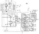
図1は、本発明の実施の形態に係る空気調和装置100の設置例を示す概略図である。図2は、本発明の実施の形態に係る空気調和装置100における冷媒回路構成の一例を示す図である。
図1に示すように、本実施の形態に係る空気調和装置100は、室外ユニット(熱源機)1と、複数台の室内ユニット3(3a〜3d)と、室外ユニット1と室内ユニット3との間に介在する1台の中継ユニット2とを有している。そして、空気調和装置100は、各室内ユニット3が冷房運転または暖房運転を選択できるものである。Hereinafter, embodiments of the present invention will be described with reference to the drawings.
Embodiment.
FIG. 1 is a schematic diagram illustrating an installation example of an
As shown in FIG. 1, an
中継ユニット2は、熱源側冷媒と熱媒体とで熱交換を行うものである。室外ユニット1と中継ユニット2とは、熱源側冷媒が流れる冷媒配管4で接続され、熱源側冷媒を循環させる冷凍サイクルである冷媒循環回路Aを構成している。中継ユニット2と室内ユニット3とは、熱媒体が流れる熱媒体配管5で接続され、熱媒体を循環させる熱媒体循環回路Bを構成している。 The
中継ユニット2は、室内ユニット3と接続するための複数の接続口60を備えている。この接続口60に熱媒体配管5を介して室内ユニット3が接続されている。なお、冷媒循環回路Aおよび熱媒体循環回路Bのそれぞれに接続される切替装置等の各構成部品については以下で改めて説明する。そして、室外ユニット1で生成された冷熱あるいは温熱は、中継ユニット2を介して室内ユニット3に配送されるようになっている。 The
本実施の形態の空気調和装置100は、接続口60(60a〜60d)に対して1台または複数台の室内ユニット3の接続が可能である。室内ユニット3aは、具体的には利用側熱交換器35a−1を備えた室内ユニット3a−1と利用側熱交換器35a−2を備えた室内ユニット3a−1との2台に分けて構成されており、接続口60aには2台の室内ユニット3a−1、3a−2が接続されている。また、接続口60b〜60dにはそれぞれ1台の室内ユニット3b〜3dが接続された構成となっている。室内ユニット3b〜3dは、利用側熱交換器35b〜35dを備えている。 In the
そして、本実施の形態は接続口60に対して熱媒体分流装置15を接続することで、一つの接続口60aに接続された2台の室内ユニット3a−1、3a−2に対して熱媒体の流量調整を可能としたことに特徴を有している。つまり、熱媒体分流装置15内へ流入した熱媒体が最適に分流されて2台の室内ユニット3a−1、3a−2に搬送され、その後、合流して熱媒体が循環するようにした点に特徴を有している。 And this Embodiment connects the heat
以下ではまず、室外ユニット1、中継ユニット2および室内ユニット3について説明し、熱媒体分流装置15については後述する。 Below, the
なお、以下では、接続口60aに接続される室内ユニット3aが2台構成であることについて特に区別する必要がない場合には、説明の便宜上、接続口60aに接続される室内ユニット3が室内ユニット3aの1台であり、室内ユニット3a内の利用側熱交換器も利用側熱交換器35aの1台であるものと見なして説明する。 In the following description, for convenience of explanation, the
室外ユニット1は、通常、ビルなどの建物9の外の空間(たとえば、屋上など)である室外空間6に配置され、中継ユニット2を介して室内ユニット3に冷熱または温熱を供給するものである。 The
中継ユニット2は、室外ユニット1で生成される温熱または冷熱を、室内ユニット3に伝達するものである。この中継ユニット2は、室外ユニット1および室内ユニット3とは別筐体として、室外空間6および室内空間7とは別の位置に設置できるように構成されている。また、中継ユニット2は、冷媒配管4を介して室外ユニット1に接続され、また、熱媒体配管5を介して室内ユニット3に接続されている。 The
室内ユニット3は、建物9の内部の空間(たとえば、居室など)である室内空間7に冷房用空気あるいは暖房用空気を供給できる位置に配置され、空調対象空間となる室内空間7に冷房用空気あるいは暖房用空気を供給するものである。図1では、室内ユニット3が天井埋込型であるものを図示しているが、これに限定されるものではない。 The
熱源側冷媒は、室外ユニット1から中継ユニット2に冷媒配管4を通して搬送される。搬送された熱源側冷媒は、中継ユニット2内の後述の熱媒体間熱交換器25a〜25d(図2参照)にて熱媒体と熱交換を行い、熱媒体を加熱または冷却する。つまり、熱媒体は、熱媒体間熱交換器で加熱または冷却されて温水または冷水となる。中継ユニット2にて作られた温水または冷水は、後述のポンプ31a、31b(図2参照)にて、熱媒体配管5を介して室内ユニット3へ搬送され、室内ユニット3にて室内空間7に対する暖房運転または冷房運転に供される。 The heat source side refrigerant is conveyed from the
熱源側冷媒としては、たとえばR−22、R−134aなどの単一冷媒、R−410A、R−404Aなどの擬似共沸混合冷媒、R−407Cなどの非共沸混合冷媒を用いることができる。熱源側冷媒として他にたとえば、化学式内に二重結合を含む、CF3、CF=CH2などの地球温暖化係数が比較的小さい値とされている冷媒、およびその混合物を用いることができる。熱源側冷媒としてはさらに、CO2またはプロパンなどの自然冷媒を用いることができる。As the heat source side refrigerant, for example, a single refrigerant such as R-22 and R-134a, a pseudo azeotropic refrigerant mixture such as R-410A and R-404A, and a non-azeotropic refrigerant mixture such as R-407C can be used. . As the heat source side refrigerant, for example, a refrigerant containing a double bond in a chemical formula and having a relatively low global warming potential such as CF 3 or CF═CH 2 and a mixture thereof can be used. Furthermore, natural refrigerants such as CO 2 or propane can be used as the heat source side refrigerant.
一方、熱媒体としては、たとえば水、ブライン(不凍液)、水と不凍液の混合液、水と防食効果が高い添加剤との混合液などを用いることができる。つまり、空気調和装置100は、熱媒体としてこれらを採用することで、室内空間7への熱媒体の漏洩に対する安全性の向上に寄与することになる。なお、本実施の形態に係る空気調和装置100は、熱媒体として水が採用されているものとして説明する。 On the other hand, as the heat medium, for example, water, brine (antifreeze), a mixed solution of water and antifreeze, a mixed solution of water and an additive having a high anticorrosive effect, or the like can be used. That is, the
図1に示すように、本実施の形態に係る空気調和装置100は、室外ユニット1と中継ユニット2とが2本の冷媒配管4を用いて接続され、中継ユニット2と各室内ユニット3とが2本の熱媒体配管5を用いて接続されている。このように、空気調和装置100では、2本の配管(冷媒配管4、熱媒体配管5)を用いて各ユニット(室外ユニット1、中継ユニット2および室内ユニット3)を接続することにより、施工が容易となっている。 As shown in FIG. 1, an
なお、図1においては、中継ユニット2が、建物9の内部ではあるが室内空間7とは別の空間である天井裏などの空間(以下、単に空間8と称する)に設置されている状態を例に示している。中継ユニット2は、その他、エレベーターなどがある共用空間などに設置することも可能である。また、図1においては、室内ユニット3が天井カセット型である場合を例に示してあるが、これに限定されるものではなく、天井埋込型や天井吊下式など、室内空間7に直接またはダクトなどにより、暖房用空気あるいは冷房用空気を吹き出せるようになっていればどんな種類のものでもよい。 In FIG. 1, the
図1においては、室外ユニット1が室外空間6に設置されている場合を例に示しているが、これに限定するものではない。たとえば、室外ユニット1は、換気口付の機械室などの囲まれた空間に設置してもよく、排気ダクトで廃熱を建物9の外に排気することができるのであれば建物9の内部に設置してもよい。また、水冷式の室外ユニット1を用いる場合にも室外ユニット1を建物9の内部に設置するようにしてもよい。このような場所に室外ユニット1を設置するとしても、特段の問題が発生することはない。 In FIG. 1, the case where the
また、中継ユニット2は、室外ユニット1の近傍に設置してもよい。ただし、このように中継ユニット2を室外ユニット1の近傍に設置する場合には、中継ユニット2から室内ユニット3までを接続する熱媒体配管5の長さについて留意するとよい。これは、中継ユニット2から室内ユニット3までの距離が長くなると、その分熱媒体の搬送動力が大きくなり、省エネルギー化の効果は薄れるためである。 Further, the
さらに、室外ユニット1、中継ユニット2および室内ユニット3の接続台数は、図1に図示される台数に限定されるものではなく、空気調和装置100が設置される建物9に応じて台数を決定すればよい。 Furthermore, the number of connected
室外ユニット1台に対して複数台の中継ユニット2を接続する場合、その複数台の中継ユニット2をビルなどの建物における共用スペースまたは天井裏などのスペースに点在して設置することができる。そうすることにより、各中継ユニット2内の後述の熱媒体間熱交換器25a、25b(図2参照)で空調負荷を賄うことができる。また、室内ユニット3を、各中継ユニット2内におけるポンプ31a、31b(図2参照)の搬送許容範囲内の距離または高さに設置することが可能であり、ビルなどの建物全体へ対しての配置が可能となる。 When a plurality of
図2は、本発明の実施の形態に係る空気調和装置100における、室外ユニット1および中継ユニット2の回路構成の一例を示す図である。
図2に示すように、室外ユニット1と中継ユニット2とが、中継ユニット2に備えられている熱媒体間熱交換器25a、25bを介して冷媒配管4で接続されている。また、中継ユニット2と室内ユニット3とが、熱媒体間熱交換器25a、25bを介して熱媒体配管5で接続されている。つまり、熱媒体間熱交換器25a、25bは、冷媒側流路と熱媒体側流路とを有し、冷媒配管4を介して冷媒側流路に供給される熱源側冷媒と、熱媒体配管5を介して熱媒体側流路に供給される熱媒体とを熱交換させるものである。FIG. 2 is a diagram illustrating an example of circuit configurations of the
As shown in FIG. 2, the
[室外ユニット1]
室外ユニット1には、圧縮機10と、四方弁などの第1冷媒流路切替装置11と、熱源側熱交換器12と、アキュムレーター19とが冷媒配管4で接続されて搭載されている。また、室外ユニット1には、第1接続配管4a、第2接続配管4b、および逆止弁13a〜13dが設けられている。第1接続配管4a、第2接続配管4b、および逆止弁13a〜13dが設けられることで、空気調和装置100は、暖房運転モードや冷房運転モードに関わらず、室外ユニット1から中継ユニット2に流入させる熱源側冷媒の流れを一定方向にすることができるようになっている。[Outdoor unit 1]
In the
圧縮機10は、冷媒を吸入し、その冷媒を圧縮して高温高圧の状態にして冷媒循環回路Aに搬送するものである。この圧縮機10は、吐出側が第1冷媒流路切替装置11に接続され、吸入側がアキュムレーター19に接続されている。圧縮機10は、たとえば容量制御可能なインバータ圧縮機などで構成するとよい。 The
第1冷媒流路切替装置11は、全暖房運転モード時および冷暖房混在運転モードの暖房主体運転モード時において、圧縮機10の吐出側と逆止弁13d、および熱源側熱交換器12とアキュムレーター19の吸入側を接続するようにするものである。また、第1冷媒流路切替装置11は、冷房運転モード時および冷暖房混在運転モードの冷房主体運転モード時において、圧縮機10の吐出側と熱源側熱交換器12とを接続するとともに、逆止弁13cとアキュムレーター19の吸入側とを接続するようにするものである。 The first refrigerant
熱源側熱交換器12は、暖房運転時には蒸発器として機能し、冷房運転時には凝縮器(または放熱器)として機能する。そして、熱源側熱交換器12は、図示省略のファンなどの送風機から供給される空気の流体と熱源側冷媒との間で熱交換を行い、その熱源側冷媒を蒸発ガス化または凝縮液化するものである。この熱源側熱交換器12は、暖房運転モード時において、一方が逆止弁13bに接続され、他方がアキュムレーター19の吸入側に接続される。また、熱源側熱交換器12は、冷房運転モード時において、一方が圧縮機10の吐出側に接続され、他方が逆止弁13aに接続される。熱源側熱交換器12は、たとえば冷媒配管を流れる冷媒とフィンを通過する空気との間で熱交換ができるようなプレートフィンアンドチューブ型熱交換器で構成するとよい。 The heat source
アキュムレーター19は、暖房運転モード時と冷房運転モード時との必要冷媒量の違いによる余剰冷媒、過渡的な運転の変化(たとえば、室内ユニット3の運転台数の変化)に対する余剰冷媒を蓄えるものである。このアキュムレーター19は、暖房運転モード時において、吸入側が熱源側熱交換器12に接続され、吐出側が圧縮機10の吸入側に接続される。また、アキュムレーター19は、冷房運転モード時において、吸入側が逆止弁13cに接続され、吐出側が圧縮機10の吸入側に接続される。 The
逆止弁13aは、熱源側熱交換器12と中継ユニット2との間における冷媒配管4に設けられ、所定の方向(室外ユニット1から中継ユニット2への方向)のみに熱源側冷媒の流れを許容するものである。
逆止弁13cは、中継ユニット2と第1冷媒流路切替装置11との間における冷媒配管4に設けられ、所定の方向(中継ユニット2から室外ユニット1への方向)のみに熱源側冷媒の流れを許容するものである。
逆止弁13bは、第2接続配管4bに設けられ、暖房運転時において中継ユニット2から戻ってきた熱源側冷媒を圧縮機10の吸入側に流通させるものである。
逆止弁13dは、第1接続配管4aに設けられ、暖房運転時において圧縮機10から吐出された熱源側冷媒を中継ユニット2に流通させるものである。The
The
The
The
第1接続配管4aは、室外ユニット1内において、第1冷媒流路切替装置11と逆止弁13cとの間における冷媒配管4と、逆止弁13aと中継ユニット2との間における冷媒配管4と、を接続するものである。第2接続配管4bは、室外ユニット1内において、逆止弁13cと中継ユニット2との間における冷媒配管4と、熱源側熱交換器12と逆止弁13aとの間における冷媒配管4と、を接続するものである。なお、図2では、第1接続配管4a、第2接続配管4b、逆止弁13a、逆止弁13b、逆止弁13c、および、逆止弁13dを設けた場合を例に示しているが、これに限定するものではなく、これらを必ずしも設ける必要はない。 In the
[室内ユニット3]
室内ユニット3には、利用側熱交換器35a〜35d(単に利用側熱交換器35とも称することもある)が備えられている。この利用側熱交換器35は、熱媒体配管5を介して熱媒体流量調整装置34a〜34d(単に熱媒体流量調整装置34とも称することもある)と、熱媒体配管5を介して第2熱媒体流路切替装置33a〜33d(単に、第2熱媒体流路切替装置33とも称することもある)に接続されている。この利用側熱交換器35は、図示省略のファンなどの送風機から供給される空気と熱媒体との間で熱交換を行い、室内空間7に供給するための暖房用空気あるいは冷房用空気を生成するものである。[Indoor unit 3]
The
図2においては、室内ユニット3a〜3dが、熱媒体配管5を介して中継ユニット2に接続されている場合の例を示している。また、室内ユニット3a〜3dに応じて、利用側熱交換器35も、紙面上側から利用側熱交換器35a、利用側熱交換器35b、利用側熱交換器35c、利用側熱交換器35dとする。なお、室内ユニット3の接続台数は、4台に限定されるものではない。 FIG. 2 shows an example in which the
[中継ユニット2]
中継ユニット2には、2つの熱媒体間熱交換器25a、25b(単に熱媒体間熱交換器25と称することもある)と、2つの絞り装置26a、26b(単に絞り装置26と称することもある)と、2つの開閉装置27、29と、2つの第2冷媒流路切替装置28a、28b(単に第2冷媒流路切替装置28と称することもある)と、が搭載されている。中継ユニット2にはさらに、2つの熱媒体搬送装置であるポンプ31a、31b(単にポンプ31と称することもある)と、4つの第1熱媒体流路切替装置32a〜32d(単に第1熱媒体流路切替装置32と称することもある)と、4つの第2熱媒体流路切替装置33a〜33d(単に第2熱媒体流路切替装置33と称することもある)と、4つの熱媒体流量調整装置34a〜34d(単に熱媒体流量調整装置34と称することもある)と、が搭載されている。[Relay unit 2]
The
なお、第1熱媒体流路切替装置32a〜32d、第2熱媒体流路切替装置33a〜33dおよび熱媒体流量調整装置34a〜34dは、これらの切替装置の機能を一元化した一体化流路切替装置に代えることも可能である。一体化流路切替装置は、具体的にはたとえば、第1熱媒体流路切替装置32a〜32d、第2熱媒体流路切替装置33a〜33dおよび熱媒体流量調整装置34a〜34dのそれぞれの機能を備えた、たとえば国際公開第2014/128961号に記載されたようなブロック(一体化)構造を有する構成としてもよい。 The first heat medium
熱媒体間熱交換器25は、凝縮器(放熱器)または蒸発器として機能し、熱源側冷媒と熱媒体とで熱交換を行い、室外ユニット1で生成され熱源側冷媒に貯えられた冷熱または温熱を熱媒体に伝達するものである。つまり、暖房運転をしている際には、熱媒体間熱交換器25は凝縮器(放熱器)として機能して熱源側冷媒の温熱を熱媒体に伝達する。また、冷房運転をしている際には、熱媒体間熱交換器25は蒸発器として機能して熱源側冷媒の冷熱を熱媒体に伝達するものである。 The heat exchanger related to heat medium 25 functions as a condenser (heat radiator) or an evaporator, performs heat exchange between the heat source side refrigerant and the heat medium, and generates heat generated by the
熱媒体間熱交換器25aは、冷媒循環回路Aにおける絞り装置26aと第2冷媒流路切替装置28aとの間に設けられており、冷暖房混在運転モード時において熱媒体の冷却に供するものである。また、熱媒体間熱交換器25bは、冷媒循環回路Aにおける絞り装置26bと第2冷媒流路切替装置28bとの間に設けられており、冷暖房混在運転モード時において熱媒体の加熱に供するものである。 The heat exchanger related to
絞り装置26は、減圧弁または膨張弁としての機能を有し、熱源側冷媒を減圧して膨張させるものである。絞り装置26aは、冷房運転時の熱源側冷媒の流れ(後述の図5参照)において熱媒体間熱交換器25aの上流側に設けられている。絞り装置26bは、冷房運転時の熱源側冷媒の流れ(後述の図5参照)において熱媒体間熱交換器25bの上流側に設けられている。絞り装置26は、開度が可変に制御可能なもの、たとえば電子式膨張弁などで構成するとよい。 The
開閉装置27および開閉装置29は、たとえば通電により開閉動作が可能な電磁弁などで構成され、それらが設けられている流路を開閉するものである。つまり、開閉装置27および開閉装置29は、運転モードに応じて開閉が制御され、熱源側冷媒の流路を切り替えている。 The opening /
開閉装置27は、熱源側冷媒の入口側における冷媒配管4(室外ユニット1と中継ユニット2とを接続している冷媒配管4のうち紙面最下段に位置する冷媒配管4)に設けられている。開閉装置29は、熱源側冷媒の入口側の冷媒配管4と出口側の冷媒配管4とを接続した配管(バイパス管20)に設けられている。なお、開閉装置27および開閉装置29は、それらが設けられている流路を開閉可能なものであればよく、たとえば電子式膨張弁などの開度を制御するものでもよい。 The opening /
第2冷媒流路切替装置28は、たとえば四方弁などで構成され、運転モードに応じて熱媒体間熱交換器25が凝縮器または蒸発器として機能するよう、熱源側冷媒の流れを切り替えるものである。第2冷媒流路切替装置28は、熱媒体間熱交換器25が凝縮器として機能する場合は図2の実線側に切り替えられ(後述の暖房運転時開度方向の切り替え)、熱媒体間熱交換器25が蒸発器として機能する場合は図2の点線側に切り替えられる(後述の冷房運転時開度方向の切り替え)。第2冷媒流路切替装置28aは、冷房運転時の熱源側冷媒の流れにおいて熱媒体間熱交換器25aの下流側に設けられている。第2冷媒流路切替装置28bは、全冷房運転モード時の熱源側冷媒の流れにおいて熱媒体間熱交換器25bの下流側に設けられている。 The second refrigerant flow switching device 28 is constituted by a four-way valve, for example, and switches the flow of the heat source side refrigerant so that the heat exchanger related to heat medium 25 functions as a condenser or an evaporator according to the operation mode. is there. When the intermediate heat exchanger 25 functions as a condenser, the second refrigerant flow switching device 28 is switched to the solid line side in FIG. 2 (switching in the opening direction during heating operation described later), and the heat between the heat medium When the exchanger 25 functions as an evaporator, it is switched to the dotted line side in FIG. 2 (switching of the opening direction during cooling operation described later). The second refrigerant
ポンプ31は、熱媒体配管5を流れる熱媒体を熱媒体循環回路Bに循環させるものである。ポンプ31aは、熱媒体間熱交換器25aと第2熱媒体流路切替装置33との間における熱媒体配管5に設けられている。ポンプ31bは、熱媒体間熱交換器25bと第2熱媒体流路切替装置33との間における熱媒体配管5に設けられている。ポンプ31は、たとえば容量制御可能なポンプなどで構成し、室内ユニット3における負荷の大きさによってその流量を調整できるようにしておくとよい。 The pump 31 circulates the heat medium flowing through the
第1熱媒体流路切替装置32は、利用側熱交換器35の熱媒体流路の出口側の接続先を、熱媒体間熱交換器25aの熱媒体流路の入口側または熱媒体間熱交換器25bの熱媒体流路の入口側に切り替えるものである。第1熱媒体流路切替装置32は、室内ユニット3の設置台数に応じた個数(ここでは4つ)が設けられるようになっている。第1熱媒体流路切替装置32は、三方のうちの一つが熱媒体間熱交換器25aに、三方のうちの一つが熱媒体間熱交換器25bに、三方のうちの一つが熱媒体流量調整装置34に、それぞれ接続され、利用側熱交換器35の熱媒体流路の出口側に設けられている。なお、室内ユニット3に対応させて、紙面上側から第1熱媒体流路切替装置32a、第1熱媒体流路切替装置32b、第1熱媒体流路切替装置32c、第1熱媒体流路切替装置32dとして図示している。また、熱媒体流路の切り替えには、一方から他方への完全な切り替えだけでなく、一方から他方への部分的な切り替えも含んでいるものとする。この第1熱媒体流路切替装置32は、たとえば三方弁などで構成するとよい。 The first heat medium flow switching device 32 connects the outlet side of the heat medium flow path of the use side heat exchanger 35 to the inlet side of the heat medium flow path of the heat
第2熱媒体流路切替装置33は、利用側熱交換器35の熱媒体流路の入口側の接続先を、熱媒体間熱交換器25aの熱媒体流路の出口側または熱媒体間熱交換器25bの熱媒体流路の出口側に切り替えるものである。第2熱媒体流路切替装置33は、室内ユニット3の設置台数に応じた個数(ここでは4つ)が設けられるようになっている。第2熱媒体流路切替装置33は、三方のうちの一つが熱媒体間熱交換器25aに、三方のうちの一つが熱媒体間熱交換器25bに、三方のうちの一つが利用側熱交換器35に、それぞれ接続され、利用側熱交換器35の熱媒体流路の入口側に設けられている。なお、室内ユニット3に対応させて、紙面上側から第2熱媒体流路切替装置33a、第2熱媒体流路切替装置33b、第2熱媒体流路切替装置33c、第2熱媒体流路切替装置33dとして図示している。また、熱媒体流路の切り替えには、一方から他方への完全な切り替えだけでなく、一方から他方への部分的な切り替えも含んでいるものとする。この第2熱媒体流路切替装置33は、たとえば三方弁などで構成するとよい。 The second heat medium flow switching device 33 connects the connection side on the inlet side of the heat medium flow path of the use side heat exchanger 35 to the outlet side of the heat medium flow path of the heat
第1熱媒体流路切替装置32および第2熱媒体流路切替装置33は本発明の熱媒体流路切替装置を構成している。 The first heat medium flow switching device 32 and the second heat medium flow switching device 33 constitute the heat medium flow switching device of the present invention.
熱媒体流量調整装置34は、開口面積を制御できる二方弁などで構成されており、熱媒体配管5に流れる熱媒体の流量を制御するものである。熱媒体流量調整装置34は、室内ユニット3の設置台数に応じた個数(ここでは4つ)が設けられるようになっている。熱媒体流量調整装置34は、一方が利用側熱交換器35に、他方が第1熱媒体流路切替装置32に、それぞれ接続され、利用側熱交換器35の熱媒体流路の出口側に設けられている。すなわち、熱媒体流量調整装置34は、室内ユニット3へ流入する熱媒体の温度および流出する熱媒体の温度により室内ユニット3へ流入する熱媒体の量を調整し、室内負荷に応じた最適な熱媒体量を室内ユニット3に提供可能とするものである。 The heat medium flow control device 34 is configured by a two-way valve or the like that can control the opening area, and controls the flow rate of the heat medium flowing through the
なお、室内ユニット3に対応させて、紙面上側から熱媒体流量調整装置34a、熱媒体流量調整装置34b、熱媒体流量調整装置34c、熱媒体流量調整装置34dとして図示している。また、熱媒体流量調整装置34を利用側熱交換器35の熱媒体流路の入口側に設けてもよい。また、熱媒体流量調整装置34を利用側熱交換器35の熱媒体流路の入口側であって、第2熱媒体流路切替装置33と利用側熱交換器35との間に設けてもよい。さらに、室内ユニット3において、停止モードおよびサーモOFFなどの負荷を必要としていないときは、熱媒体流量調整装置34を全閉にすることにより、室内ユニット3への熱媒体供給を止めることができる。 In correspondence with the
なお、第1熱媒体流路切替装置32または第2熱媒体流路切替装置33において、熱媒体流量調整装置34の機能を付加したものを用いれば、熱媒体流量調整装置34を省略することも可能である。 If the first heat medium flow switching device 32 or the second heat medium flow switching device 33 is added with the function of the heat medium flow control device 34, the heat medium flow control device 34 may be omitted. Is possible.
また、前述の通り、第1熱媒体流路切替装置32、第2熱媒体流路切替装置33および熱媒体流量調整装置34を一体化(ブロック化)し、流路切替機能、流量調整機能、流路閉止機能を付加した一体化流路切替装置を第1熱媒体流路切替装置32、第2熱媒体流路切替装置33および熱媒体流量調整装置34に対して代用することもできる。 Further, as described above, the first heat medium flow switching device 32, the second heat medium flow switching device 33, and the heat medium flow control device 34 are integrated (blocked), and the flow switch function, the flow control function, An integrated flow path switching device to which a flow path closing function is added can be substituted for the first heat medium flow path switching device 32, the second heat medium flow path switching device 33, and the heat medium flow rate adjustment device.
また、中継ユニット2には、2つの温度センサー40a、40b(単に温度センサー40と称することもある)が設けられている。温度センサー40は、熱媒体間熱交換器25から流出した熱媒体、つまり熱媒体間熱交換器25の出口における熱媒体の温度を検出するものである。温度センサー40aは、ポンプ31aの熱媒体吸入側における熱媒体配管5に設けられている。温度センサー40bは、ポンプ31bの熱媒体吸入側における熱媒体配管5に設けられている。温度センサー40は、たとえばサーミスターなどで構成するとよい。 The
温度センサー40で検出された情報(温度情報)は、空気調和装置100の動作を統括制御する制御装置50に送られる。そして、温度センサー40で検出された情報(温度情報)は、圧縮機10の駆動周波数、図示省略の送風機の回転数、第1冷媒流路切替装置11の切り替え、ポンプ31の駆動周波数、第2冷媒流路切替装置28の切り替え、熱媒体の流路の切り替え、室内ユニット3の熱媒体流量の調整などの制御に利用されることになる。なお、制御装置50が中継ユニット2内に搭載されている状態を例に示しているが、これに限定するものではなく、室外ユニット1または室内ユニット3、あるいは、各ユニットに通信可能に搭載するようにしてもよい。 Information (temperature information) detected by the temperature sensor 40 is sent to the
また、制御装置50は、マイコンなどで構成されており、各種検出手段での検出結果およびリモコンからの指示に基づいて、圧縮機10の駆動周波数、送風機の回転数(ON/OFF含む)、第1冷媒流路切替装置11の切り替え、ポンプ31の駆動、絞り装置26の開度を制御する。制御装置50はこれらの他にも、第2冷媒流路切替装置28の切り替え、第1熱媒体流路切替装置32の切り替え、第2熱媒体流路切替装置33の切り替え、熱媒体流量調整装置34の駆動、開閉装置27、29の開閉、および後述の熱媒体分流調整弁36の開度などを制御する。つまり、制御装置50は、これらの各種機器を構成するアクチュエーターなどを制御して、後述する各運転モードを実行するようになっている。 Further, the
制御装置50は、具体的には室内空間7が設定温度を維持するように制御を行っており、室内空間7が設定温度に達すると、室内ユニット3に設けられた利用側熱交換器35への熱媒体の供給を停止させる(サーモOFF)。また、制御装置50は、室内空間7が設定温度に達していなくとも、ユーザーからの指示があれば、室内ユニット3に設けられた利用側熱交換器35への熱媒体の供給を停止させるだけでなく、利用側熱交換器35に付設されるファンの運転も停止させる。 Specifically, the
熱媒体が流れる熱媒体配管5は、熱媒体間熱交換器25aに接続されるものと、熱媒体間熱交換器25bに接続されるものと、を有している。熱媒体配管5は、室内ユニット3との接続口60の数に応じて分岐(ここでは、各4分岐)されている。そして、熱媒体配管5のうち熱媒体間熱交換器25aに接続されるものと、熱媒体間熱交換器25bに接続されるものとが、第1熱媒体流路切替装置32、および、第2熱媒体流路切替装置33で接続される。第1熱媒体流路切替装置32および第2熱媒体流路切替装置33を制御することで、熱媒体間熱交換器25aからの熱媒体を利用側熱交換器35に流入させるか、熱媒体間熱交換器25bからの熱媒体を利用側熱交換器35に流入させるかが決定されるようになっている。 The
そして、空気調和装置100では、圧縮機10、第1冷媒流路切替装置11、熱源側熱交換器12、開閉装置27、開閉装置29、第2冷媒流路切替装置28、熱媒体間熱交換器25の冷媒流路、絞り装置26、および、アキュムレーター19を、冷媒配管4で接続して冷媒循環回路Aを構成している。また、熱媒体間熱交換器25の熱媒体流路、ポンプ31、第1熱媒体流路切替装置32、熱媒体流量調整装置34、利用側熱交換器35、および、第2熱媒体流路切替装置33を、熱媒体配管5で接続して熱媒体循環回路Bを構成している。つまり、熱媒体間熱交換器25のそれぞれに複数台の利用側熱交換器35が並列に接続され、熱媒体循環回路Bを複数系統としている。ここでは接続口60が4つあるため、4系統の熱媒体循環回路Bが構成されている。 In the
よって、空気調和装置100では、室外ユニット1と中継ユニット2とが、中継ユニット2に設けられている熱媒体間熱交換器25aおよび熱媒体間熱交換器25bを介して接続され、中継ユニット2と室内ユニット3とが、熱媒体間熱交換器25aおよび熱媒体間熱交換器25bを介して接続されている。すなわち、空気調和装置100では、熱媒体間熱交換器25aおよび熱媒体間熱交換器25bで冷媒循環回路Aを循環する熱源側冷媒と熱媒体循環回路Bを循環する熱媒体とが熱交換するようになっている。このような構成を用いることで、空気調和装置100は、室内負荷に応じた最適な冷房運転または暖房運転を実現することができる。 Therefore, in the
また、空気調和装置100では、上述したように熱媒体循環回路Bが、熱媒体循環回路Bに流れる熱媒体を複数(ここでは2つ)に分流して室内ユニット3a−1、3a−2に並列に流す2つの分流並列回路70a、70bを有している。そして、本実施の形態の空気調和装置100は、接続口60aに対して熱媒体分流装置15を接続することで、室内ユニット3a−1、3a−2のそれぞれの熱媒体の流量調整が可能となっている。以下、熱媒体分流装置15について説明する。 Further, in the
[熱媒体分流装置15]
図3は、本発明の実施の形態に係る空気調和装置の熱媒体分流装置15の構成模式図である。
図3に示すように、熱媒体分流装置15は、熱媒体循環回路Bの一部を構成しており、中継ユニット2との接続用の第1接続口61と、室内ユニット3a−1、3a−2との接続用の第2接続口62とを備えている。第1接続口61は、入口側接続口61aと出口側接続口61bとを有する。そして、この第1接続口61を介して中継ユニット2と熱媒体分流装置15とが熱媒体配管5で接続されている。また、第2接続口62は、出口側接続口62aと入口側接続口62bとを有している。入口側接続口62bと出口側接続口62aとのそれぞれは、一系統の熱媒体循環回路Bに対して接続可能な室内ユニットの台数分、ここでは2つずつ備えられている。[Heat medium diverter 15]
FIG. 3 is a schematic configuration diagram of the
As shown in FIG. 3, the
また、熱媒体分流装置15は、分流配管16と合流配管17とを有している。分流配管16は、入口側接続口61aと出口側接続口62aとを接続し、入口側接続口61aから流入した、中継ユニット2からの熱媒体を分流して複数の出口側接続口62aに導くものである。合流配管17は、複数の入口側接続口62bと出口側接続口61bとを接続し、複数の入口側接続口62bから流入した、室内ユニット3a−1、3a−2からの各熱媒体を合流して出口側接続口61bに導くものである。 Further, the heat
そして、分流配管16には熱媒体分流調整弁36が設けられている。熱媒体分流調整弁36は、中継ユニット2から熱媒体分流装置15へ流入した熱媒体循環回路Bの熱媒体を任意の分流比率で分流して、利用側熱交換器35a−1、35a−2の流量を調整するものである。熱媒体分流調整弁36はたとえばステッピングモータを備え、指示開度毎に開口面積を変更することができる三方弁である。熱媒体分流調整弁36は、指示開度が大きくなるにつれ、利用側熱交換器35a−1側に流入する熱媒体の量が増える一方、利用側熱交換器35a−2側に流入する熱媒体の量が減るようにしている。 The
熱媒体分流装置15はさらに温度センサー41および温度センサー42a、42bを備えている。温度センサー41は熱媒体分流装置15に流入する熱媒体の温度を検知する。温度センサー42a、41−bは、利用側熱交換器35a−1、35a−2で熱交換後の熱媒体の温度を検知する。なお、温度センサー41および温度センサー42a、42bは本発明の温度検知装置を構成している。 The
これらの温度センサーはたとえばサーミスターなどで構成される。熱媒体分流調整弁36は、これらの温度センサーで検知された温度に基づいて、利用側熱交換器35a−1、35a−2に対して最適な熱媒体流量が搬送されるように調整される。熱媒体分流調整弁36は、室内ユニット3a−1、3a−2のそれぞれの負荷に応じて制御装置50によって制御される。熱媒体分流調整弁36の制御の詳細については改めて詳述する。 These temperature sensors are composed of, for example, a thermistor. The heat medium
[運転モード]
空気調和装置100が実行する各運転モードについて説明する。この空気調和装置100は、各室内ユニット3からの指示に基づいて、その室内ユニット3で暖房運転または冷房運転が可能になっている。つまり、空気調和装置100は、室内ユニット3の全部で同一運転をすることができるとともに、室内ユニット3のそれぞれで異なる運転をすることができるようになっている。[Operation mode]
Each operation mode which the
空気調和装置100が実行する運転モードには、以下の4つのモードがある。以下に、各運転モードについて、熱源側冷媒および熱媒体の流れとともに説明する。 The operation modes executed by the
(a)動作している室内ユニット3の全てが冷房運転を実行する全冷房運転モード
(b)動作している室内ユニット3の全てが暖房運転を実行する全暖房運転モード
(c)冷房運転と暖房運転を実行する室内ユニット3が混在する冷暖房混在運転モードであって、冷房負荷の方が大きい冷房主体運転モード
(d)冷房運転と暖房運転を実行する室内ユニット3が混在する冷暖房混在運転モードであって、暖房負荷の方が大きい暖房主体運転モード(A) All-cooling operation mode in which all the operating
以下に、これらの各モードについて説明する。なお、室内ユニット3aは、上述したように室内ユニット3a−1と室内ユニット3a−2との2台に分けて構成されているが、各モードの基本動作の概要を説明する観点から、以下の各モードの説明では便宜上、2台に区別せず、1台の室内ユニット3aとして説明する。そして、室内ユニット3a−1、3a−2への熱媒体の分流については改めて詳述する。 Hereinafter, each of these modes will be described. In addition, although the
[暖房運転モード(全暖房モード)]
図4は、図2に示す空気調和装置100の暖房運転モード時における冷媒の流れを示す冷媒回路図である。この図4では、4つの室内ユニット3a〜3dが暖房運転モードの状態を一例として説明する。
なお、図4では、太線で表された配管が熱源側冷媒の流れる配管を示している。また、図4では、熱源側冷媒の流れ方向を実線矢印で示し、熱媒体の流れ方向を点線矢印で示している。[Heating operation mode (all heating mode)]
FIG. 4 is a refrigerant circuit diagram illustrating a refrigerant flow when the air-
In addition, in FIG. 4, the piping represented by the thick line has shown the piping through which the heat source side refrigerant | coolant flows. Moreover, in FIG. 4, the flow direction of the heat source side refrigerant is indicated by a solid line arrow, and the flow direction of the heat medium is indicated by a dotted line arrow.
暖房運転モード(全暖房モード)の場合、室外ユニット1では、第1冷媒流路切替装置11を、圧縮機10から吐出された熱源側冷媒を熱源側熱交換器12を経由させずに中継ユニット2へ流入させるように切り替える。 In the heating operation mode (all heating mode), the
中継ユニット2では、4つの室内ユニット3が暖房運転モードであるので、4つの第1熱媒体流路切替装置32a〜32dと、4つの第2熱媒体流路切替装置33a〜33dとは暖房側開度方向に切り替えられるかまたは中間開度とされる。暖房側開度方向に切り替えられるとは、熱媒体間熱交換器25a、25bのうち、凝縮器として機能する側に切り替えられることを指す。ここでは全暖房運転モードであり、熱媒体間熱交換器25a、25bの両方が凝縮器として機能するため、熱媒体間熱交換器25a、25bのうちのどちらか一方側に切り替えられることを指すことになる。また、中間開度とは、熱媒体間熱交換器25aおよび熱媒体間熱交換器25bの双方へ流れる流路が確保されるように、中間的な開度にされることを指す。 In the
また、開閉装置27は閉、開閉装置29は開となっている。また、4つの熱媒体流量調整装置34a〜34dは、熱媒体流量調整時開度とする。すなわち、4つの熱媒体流量調整装置34a〜34dは室内ユニット3a〜3dがそれぞれ設置された室内にて必要とされる空調負荷を賄うのに必要な流量が得られるように制御される。 The opening /
なお、ポンプ31の動作は室内ユニット負荷に応じた流量指示値となっている。また、第2冷媒流路切替装置28の切り替え状態は、暖房運転時開度方向となっている。 The operation of the pump 31 is a flow rate instruction value corresponding to the indoor unit load. The switching state of the second refrigerant flow switching device 28 is the opening direction during heating operation.
まず始めに、冷媒循環回路Aにおける熱源側冷媒の流れについて説明する。
低温低圧の冷媒が圧縮機10によって圧縮され、高温高圧のガス冷媒となって吐出される。圧縮機10から吐出された高温高圧のガス冷媒は、第1冷媒流路切替装置11、および第1接続配管4aを介して室外ユニット1から流出する。室外ユニット1から流出した高温高圧のガス冷媒は、冷媒配管4を通って中継ユニット2に流入する。中継ユニット2に流入した高温高圧のガス冷媒は、第2冷媒流路切替装置28a、28bを通過した後、熱媒体間熱交換器25a、25bを通過し、絞り装置26a、26bを通過し、開閉装置29を通過する。開閉装置29を通過後の冷媒は、室外ユニット1へと搬送され、熱源側熱交換器12にて外気との熱交換を行って低温低圧のガス冷媒となる。低温低圧のガス冷媒は、第1冷媒流路切替装置11およびアキュムレーター19を介して圧縮機10へ再度吸入される。First, the flow of the heat source side refrigerant in the refrigerant circuit A will be described.
The low-temperature and low-pressure refrigerant is compressed by the
このとき、絞り装置26a、26bは、熱媒体間熱交換器25a、25bの出口冷媒のサブクール(過冷却度)が一定になるように開度が制御される。このサブクール(過冷却度)は、熱媒体間熱交換器25a、25bと絞り装置26a、26bとの間を流れる熱源側冷媒の圧力を飽和温度に換算した値と、熱媒体間熱交換器25a、25bの出口側の温度との差として得られるものである。 At this time, the opening degree of the
次に、熱媒体循環回路Bにおける熱媒体の流れについて説明する。 Next, the flow of the heat medium in the heat medium circuit B will be described.
全暖房運転モードでは、熱媒体間熱交換器25aおよび熱媒体間熱交換器25bの双方で熱源側冷媒の温熱が熱媒体に伝えられ、暖められた熱媒体がポンプ31aおよびポンプ31bによって熱媒体配管5内を流動させられることになる。ポンプ31aおよびポンプ31bの駆動によって加圧された熱媒体は、利用側熱交換器35a〜35dに送り込まれ、室内空気と熱交換した後、利用側熱交換器35a〜35dから流出して熱媒体流量調整装置34a〜34dに流入する。このとき、熱媒体は、熱媒体流量調整装置34a〜34dの作用によって室内にて必要とされる空調負荷を賄うのに必要な流量に制御されて利用側熱交換器35a〜35dおよび熱媒体流量調整装置34a〜34dを通過するようになっている。 In the heating only operation mode, the heat of the heat source side refrigerant is transmitted to the heat medium in both the heat exchanger related to
そして、熱媒体流量調整装置34a〜34dから流出した熱媒体は、第1熱媒体流路切替装置32a〜32dにより流路が切り替えられて熱媒体配管5を通り、熱媒体間熱交換器25aおよび熱媒体間熱交換器25bへ流入通過し、再びポンプ31aおよびポンプ31bへ吸い込まれる。 The heat medium flowing out of the heat medium flow control devices 34a to 34d is switched by the first heat medium
[冷房運転モード(全冷房モード)]
図5は、図2に示す空気調和装置100の全冷房モード時における冷媒の流れを示す冷媒回路図である。この図5では、4つの室内ユニット3a〜3dが冷房運転モードの状態を一例として説明する。
なお、図5では、太線で表された配管が熱源側冷媒の流れる配管を示している。また、図5では、熱源側冷媒の流れ方向を実線矢印で示し、熱媒体の流れ方向を点線矢印で示している。[Cooling operation mode (all cooling mode)]
FIG. 5 is a refrigerant circuit diagram showing the flow of the refrigerant when the air-
In FIG. 5, the pipes represented by the thick lines indicate the pipes through which the heat source side refrigerant flows. In FIG. 5, the flow direction of the heat source side refrigerant is indicated by solid arrows, and the flow direction of the heat medium is indicated by dotted arrows.
冷房運転モード(全冷房モード)の場合、室外ユニット1では、第1冷媒流路切替装置11を圧縮機10から吐出された熱源側冷媒を熱源側熱交換器12へ流入させるように切り替える。 In the cooling operation mode (all cooling mode), in the
中継ユニット2では、4つの室内ユニット3が冷房運転モードであるので、4つの第1熱媒体流路切替装置32a〜32d、4つの第2熱媒体流路切替装置33a〜33dは冷房側開度方向または中間開度とする。4つの熱媒体流量調整装置34a〜34dは熱媒体流量調整時開度とする。また、開閉装置27は開、開閉装置29は閉となっている。絞り装置26aおよび絞り装置26bは熱媒体冷媒流量調整時開度となっている。 In the
なお、ポンプ31の動作は室内ユニット負荷に応じた流量指示値となっている。第2冷媒流路切替装置28の切り替え状態は、冷房運転時開度方向となっている。 The operation of the pump 31 is a flow rate instruction value corresponding to the indoor unit load. The switching state of the second refrigerant flow switching device 28 is the opening direction during the cooling operation.
まず始めに、冷媒循環回路Aにおける熱源側冷媒の流れについて説明する。
低温低圧の冷媒が圧縮機10によって圧縮され、高温高圧のガス冷媒となって吐出される。圧縮機10から吐出された高温高圧のガス冷媒は、第1冷媒流路切替装置11を介して熱源側熱交換器12に流入する。熱源側熱交換器12に流入した冷媒は、外気との熱交換を行い、高温高圧の液または二相冷媒となり、熱源側熱交換器12から流出する。熱源側熱交換器12から流出した冷媒は、逆止弁13aを通過した後、室外ユニット1から流出する。室外ユニット1から流出した高温高圧の液または二相冷媒は、冷媒配管4を通って中継ユニット2に流入する。First, the flow of the heat source side refrigerant in the refrigerant circuit A will be described.
The low-temperature and low-pressure refrigerant is compressed by the
中継ユニット2に流入した高温高圧の液または二相冷媒は、開閉装置27を通過した後、絞り装置26a、26bで膨張させられて、低温低圧の二相冷媒となる。この二相冷媒は、熱媒体間熱交換器25a、25bにて熱媒体と熱交換した後、低温低圧のガス冷媒となる。熱媒体間熱交換器25aおよび熱媒体間熱交換器25bから流出したガス冷媒は、第2冷媒流路切替装置28aおよび第2冷媒流路切替装置28bを通った後、合流し、中継ユニット2から流出する。中継ユニット2を流出した冷媒は、冷媒配管4および逆止弁13cを通過して、第1冷媒流路切替装置11およびアキュムレーター19を介して圧縮機10へ再度吸入される。 The high-temperature and high-pressure liquid or two-phase refrigerant that has flowed into the
このとき絞り装置26は、熱媒体間熱交換器25と絞り装置26との間を流れる熱源側冷媒の圧力を飽和温度換算した値と、熱媒体間熱交換器25の出口側の温度との差として得られるスーパーヒート(過熱度)が一定になるように開度が制御される。なお、熱媒体間熱交換器25の中間位置の温度が測定できる場合は、その中間位置での温度を換算した飽和温度を代わりに用いてもよい。この場合、圧力センサーを設置しなくて済み、安価にシステムを構成できる。 At this time, the
次に、熱媒体循環回路Bにおける熱媒体の流れについて説明する。
全冷房運転モードでは、熱媒体間熱交換器25aおよび熱媒体間熱交換器25bの双方で熱源側冷媒へ熱媒体の冷熱が伝えられ、冷却された熱媒体がポンプ31aおよびポンプ31bによって熱媒体配管5内を流動させられることになる。全冷房運転モードにおける熱媒体循環回路Bにおける熱媒体の流れは、図4で説明した全暖房時の熱媒体の流れと同じである。すなわち、ポンプ31aおよびポンプ31bの駆動によって加圧された熱媒体は、利用側熱交換器35a〜35dに送り込まれ、室内空気と熱交換した後、利用側熱交換器35a〜35dから流出して熱媒体流量調整装置34a〜34dに流入する。このとき、熱媒体は、熱媒体流量調整装置34a〜34dの作用によって室内にて必要とされる空調負荷を賄うのに必要な流量に制御されて利用側熱交換器35a〜35dおよび熱媒体流量調整装置34a〜34dを通過するようになっている。Next, the flow of the heat medium in the heat medium circuit B will be described.
In the all-cooling operation mode, the cold heat of the heat medium is transmitted to the heat source side refrigerant in both of the heat exchangers between
そして、熱媒体流量調整装置34a〜34dから流出した熱媒体は、第1熱媒体流路切替装置32a〜32dにより流路が切り替えられて熱媒体配管5を通り、熱媒体間熱交換器25aおよび熱媒体間熱交換器25bへ流入通過し、再びポンプ31aおよびポンプ31bへ吸い込まれる。 The heat medium flowing out of the heat medium flow control devices 34a to 34d is switched by the first heat medium
[混在運転モード(暖房主体モード)]
図6は、図2に示す空気調和装置100の混在運転モード時のうち、暖房主体運転時における冷媒の流れを示す冷媒回路図である。ここでは、4つの室内ユニット3a〜3dのうち室内ユニット3aが暖房運転モード、室内ユニット3dが冷房運転モードであり、暖房運転割合の方が冷房運転割合より大きい場合の運転状態を一例として混在運転モードを説明する。そして、その他の室内ユニット3b、3cは、運転停止により負荷がかからず(室内を冷却、加熱する必要がない。サーモオフしている状態を含む)、利用側熱交換器35b、35cに熱媒体が流れないようにするものとする。[Mixed operation mode (heating main mode)]
FIG. 6 is a refrigerant circuit diagram illustrating a refrigerant flow during heating-main operation in the mixed operation mode of the air-
なお、図6では、太線で表された配管が熱源側冷媒の流れる配管を示している。また、図6では、熱源側冷媒の流れ方向を実線矢印で示し、熱媒体の流れ方向を点線矢印で示している。 In addition, in FIG. 6, the piping represented by the thick line has shown the piping through which the heat source side refrigerant | coolant flows. In FIG. 6, the flow direction of the heat source side refrigerant is indicated by a solid line arrow, and the flow direction of the heat medium is indicated by a dotted line arrow.
混在運転モード(暖主運転モード)の場合、室外ユニット1では、第1冷媒流路切替装置11を、圧縮機10から吐出された熱源側冷媒を熱源側熱交換器12を経由させずに中継ユニット2へ流入させるように切り替える。 In the mixed operation mode (warm main operation mode), in the
中継ユニット2では、4つの室内ユニット3のうちの室内ユニット3bが暖房運転モード、室内ユニット3dが冷房運転モードであるので、4つの第1熱媒体流路切替装置32a〜32d、4つの第2熱媒体流路切替装置33a〜33dのうち、暖房運転モードの室内ユニット3aに接続されている第2熱媒体流路切替装置33aは、暖房側開度方向に切り替えられる。すなわち、熱媒体間熱交換器25a、25bのうち、凝縮器として機能する熱媒体間熱交換器25b側に切り替えられる。また、冷房運転モードの室内ユニット3dに接続されている第2熱媒体流路切替装置33dは、冷房側開度方向に切り替えられる。つまり、第2熱媒体流路切替装置33dは、熱媒体間熱交換器25a、25bのうち、蒸発器として機能する熱媒体間熱交換器25a側に切り替えられる。 In the
また、4つの熱媒体流量調整装置34a〜34dについては熱媒体流量調整時開度とする。また、開閉装置27は閉、開閉装置29は閉となっている。絞り装置26aおよび絞り装置26bは熱媒体冷媒流量調整時開度となっている。
なお、ポンプ31の動作は室内ユニット負荷に応じた流量指示値となっている。第2冷媒流路切替装置28aの切り替え状態は冷房運転時開度方向、第2冷媒流路切替装置28bの切り替え状態は暖房運転時開度方向となっている。Moreover, it is set as the opening degree at the time of heat-medium flow rate adjustment about four heat-medium flow rate adjustment apparatuses 34a-34d. The opening /
The operation of the pump 31 is a flow rate instruction value corresponding to the indoor unit load. The switching state of the second refrigerant
まず始めに、冷媒循環回路Aにおける熱源側冷媒の流れについて説明する。
低温低圧の冷媒が圧縮機10によって圧縮され、高温高圧のガス冷媒となって吐出される。圧縮機10から吐出された高温高圧のガス冷媒は、第1冷媒流路切替装置11、および第1接続配管4aを介して室外ユニット1から流出する。室外ユニット1から流出した高温高圧のガス冷媒は、冷媒配管4を通って中継ユニット2に流入する。中継ユニット2に流入した高温高圧のガス冷媒は、第2冷媒流路切替装置28bを通過した後、凝縮器として機能する熱媒体間熱交換器25bを通過する。熱媒体間熱交換器25bを通過した冷媒は、絞り装置26bおよび絞り装置26bを通過して減圧され、蒸発器として機能する熱媒体間熱交換器25aへと流入する。First, the flow of the heat source side refrigerant in the refrigerant circuit A will be described.
The low-temperature and low-pressure refrigerant is compressed by the
熱媒体間熱交換器25aを流出した冷媒は、その後、第2冷媒流路切替装置28aを通過した後、中継ユニット2から流出する。中継ユニット2から流出した冷媒は、冷媒配管4を通って室外ユニット1へと搬送され、熱源側熱交換器12にて外気との熱交換を行った後、低温低圧となったガス冷媒となる。低温低圧のガス冷媒は、第1冷媒流路切替装置11およびアキュムレーター19を介して圧縮機10へ再度吸入される。 The refrigerant that has flowed out of the heat exchanger related to
このとき、絞り装置26bは、熱媒体間熱交換器25bと絞り装置26bとの間を流れる熱源側冷媒の圧力を飽和温度に換算した値と、熱媒体間熱交換器25bの出口側の温度との差として得られるサブクール(過冷却度)が一定になるように開度が制御される。 At this time, the
また、絞り装置26aは熱媒体間熱交換器25aと絞り装置26aとの間を流れる熱源側冷媒の圧力を飽和温度換算した値と、熱媒体間熱交換器25aの出口側の温度との差として得られるスーパーヒート(過熱度)が一定になるように開度が制御される。 Further, the
次に、熱媒体循環回路Bにおける熱媒体の流れについて説明する。 Next, the flow of the heat medium in the heat medium circuit B will be described.
暖房主体運転モードでは、熱媒体間熱交換器25bで熱源側冷媒の温熱が熱媒体に伝えられ、暖められた熱媒体がポンプ31bによって熱媒体配管5内を流動させられることになる。また、暖房主体運転モードでは、熱媒体間熱交換器25aで熱源側冷媒の冷熱が熱媒体に伝えられ、冷やされた熱媒体がポンプ31aによって熱媒体配管5内を流動させられることになる。 In the heating main operation mode, the heat of the heat source side refrigerant is transmitted to the heat medium in the heat exchanger related to
ポンプ31bの駆動によって加圧された熱媒体は、利用側熱交換器35aに送り込まれ、室内空気と熱交換して室内を暖房した後、利用側熱交換器35aから流出する。利用側熱交換器35aから流出した熱媒体は、熱媒体流量調整装置34aおよび第1熱媒体流路切替装置32aを通過した後、熱媒体間熱交換器25aへ流入通過する。そして、熱媒体間熱交換器25aを通過した熱媒体は、再びポンプ31bへ吸い込まれた後、第2熱媒体流路切替装置33aを通過して利用側熱交換器35aに送り込まれる。 The heat medium pressurized by the drive of the
一方、ポンプ31aの駆動によって加圧された熱媒体は、利用側熱交換器35dに送り込まれ、室内空気と熱交換して室内を冷房した後、利用側熱交換器35dから流出する。熱媒体流量調整装置34eを通過した熱媒体は、熱媒体流量調整装置34dおよび第1熱媒体流路切替装置32dを通過した後、熱媒体間熱交換器25aへ流入通過する。そして、熱媒体間熱交換器25aを通過した熱媒体は、再びポンプ31aへ吸い込まれた後、第2熱媒体流路切替装置33dを通過して利用側熱交換器35dに送り込まれる。 On the other hand, the heat medium pressurized by the driving of the
以上により、空気調和装置100の基本的な動作が明らかになったところで、熱媒体分流装置15の制御について説明する。 With the above, when the basic operation of the
[熱媒体分流装置15]
以下、熱媒体分流装置15に備えている熱媒体分流調整弁36の制御方法について説明する。ここでは、熱媒体間熱交換器25bが凝縮器として機能し、室内ユニット3aが暖房運転モードで動作する場合を例に説明する。なお、4系統の熱媒体循環回路Bのそれぞれに流入する熱媒体の流量は、室内ユニット3a〜3dのそれぞれの熱負荷に応じて熱媒体流量調整装置34a〜34dにて制御されており、熱媒体分流装置15では室内ユニット3aに対して割り当てられた流量の熱媒体をさらに室内ユニット3a−1、3a−2の熱負荷に応じて分流して、利用側熱交換器35a−1、35a−2に流入させるものである。[Heat medium diverter 15]
Hereinafter, a method for controlling the heat medium
中継ユニット2にて、熱媒体間熱交換器25aにて吸熱した熱媒体はポンプ31bから搬送され、熱媒体分流装置15へ流入する。熱媒体分流装置15へ流入した熱媒体の温度は温度センサー41にて検知される。熱媒体分流装置15へ流入した熱媒体は熱媒体分流調整弁36へと流入し、室内ユニット3a−1、3a−2のそれぞれの熱負荷である空調負荷に応じて最適な開度調整によって分流される。分流された各熱媒体は熱媒体分流装置15出口下流側へ接続された利用側熱交換器35a−1、35a−2へと流入され、室内空間7の空気に対して放熱が行われる。 In the
室内空間7の空気に対して放熱が行われた各熱媒体は、再び熱媒体分流装置15へと流入して合流し、再び中継ユニット2へと搬送される。 The heat mediums that have radiated heat to the air in the indoor space 7 flow into the
熱媒体分流調整弁36は、室内空間7で必要とされている空調負荷を賄うために以下のように制御される。すなわち、熱媒体分流調整弁36は、利用側熱交換器35a−1、35a−2のそれぞれの出入口の熱媒体の温度差を目標温度差ΔTmに保つように制御される。目標温度差ΔTmは、利用側熱交換器35a−1、利用側熱交換器35a−2における熱交換量と熱媒体の流量とから設定される目標値である。以下、数式を用いて熱媒体分流調整弁36の制御量について具体的に説明する。 The heat medium branching
熱媒体分流調整弁36に指示される開度Fjは、利用側熱交換器35a−1、35a−2のそれぞれの空調負荷に応じて決定される開度変更量をΔFjとし、前回の熱媒体分流調整弁36の指示開度をFj*としたとき、以下の(式1)で算出できる。 The opening degree Fj instructed to the heat medium
[数1]
Fj=Fj*+ΔFj ・・・ (式1)[Equation 1]
Fj = Fj * + ΔFj (Formula 1)
開度Fjは、利用側熱交換器35a−1、35a−2のそれぞれの負荷に応じて必要とされる開度、つまり必要開度と言うこともできる。 The opening degree Fj can also be said to be an opening degree that is required according to each load of the use
また、開度変更量ΔFjは以下の(式2)から求められる。 Further, the opening change amount ΔFj is obtained from the following (Equation 2).
[数2]
ΔFj=(ΔFj1+ΔFj2)/2 ・・・ (式2)
ここで、
ΔFj1:利用側熱交換器35a−1の負荷に応じて必要とされる熱媒体分流調整弁36の開度変更量
ΔFj2:利用側熱交換器35a−2の負荷に応じて必要とされる熱媒体分流調整弁36の開度変更量[Equation 2]
ΔFj = (ΔFj1 + ΔFj2) / 2 (Expression 2)
here,
ΔFj1: Amount of change in the opening degree of the heat medium
以上の(式2)から明らかなように、開度変更量ΔFjは、利用側熱交換器35a−1、35a−2のそれぞれで必要とされる開度変更量ΔFj1と開度変更量ΔFj2との平均値である。開度変更量ΔFjの算出式は、平均開度変更量を計算できるものであれば、(式2)に限ったものではない。 As is clear from the above (Equation 2), the opening change amount ΔFj is determined by the opening change amount ΔFj1 and the opening change amount ΔFj2 required in each of the use
利用側熱交換器35a−1、35a−2のそれぞれの負荷に応じて必要とされる熱媒体分流調整弁36の開度変更量ΔFj1、ΔFj2は、利用側熱交換器35a−1、35a−2の出入口の熱媒体温度と、目標温度差ΔTmと、熱媒体分流調整弁36における制御ゲインGsとを用いて以下の式で算出できる。 The opening change amounts ΔFj1 and ΔFj2 of the heat medium
(利用側熱交換器35a−1)
[数3]
ΔTm≧ΔT1のとき ΔFj1=Gs×(ΔTm−ΔT1) ・・・ (式3)
[数4]
ΔTm<ΔT1のとき ΔFj1=Gs×(ΔT1−ΔTm) ・・・ (式4)(Use
[Equation 3]
When ΔTm ≧ ΔT1, ΔFj1 = Gs × (ΔTm−ΔT1) (Formula 3)
[Equation 4]
When ΔTm <ΔT1, ΔFj1 = Gs × (ΔT1−ΔTm) (Formula 4)
(利用側熱交換器35a−2)
[数5]
ΔTm≧ΔT2のとき ΔFj2=Gs×(ΔTm−ΔT2) ・・・ (式5)
[数6]
ΔTm<ΔT2のとき ΔFj2=Gs×(ΔT2−ΔTm) ・・・ (式6)(Use
[Equation 5]
When ΔTm ≧ ΔT2, ΔFj2 = Gs × (ΔTm−ΔT2) (Formula 5)
[Equation 6]
When ΔTm <ΔT2, ΔFj2 = Gs × (ΔT2−ΔTm) (Expression 6)
このとき、
[数7]
ΔT1=|(温度センサ42a値)−(温度センサ41値)| ・・・ (式7)
[数8]
ΔT2=|(温度センサ42b値)−(温度センサ41値)| ・・・ (式8)At this time,
[Equation 7]
ΔT1 = | (
[Equation 8]
ΔT2 = | (
なお、制御ゲインGsは、熱媒体分流調整弁36の開度速度、利用側熱交換器35a−1、35a−2の熱負荷に対する応答性、によって決定される。また、ΔT1は(式7)より明かなように、利用側熱交換器35a−1における熱交換前後の熱媒体の温度差である。ΔT2は(式8)より明かなように利用側熱交換器35a−2における熱交換前後の熱媒体の温度差である。 The control gain Gs is determined by the opening speed of the heat medium
開度変更量ΔFj1、ΔFj2は利用側熱交換器35a−1、35a−2における熱交換前後の現在の熱媒体温度差と目標温度差ΔTmとの差が大きい程、大きな値に決定され、逆に目標温度差ΔTmとの差が小さい程、小さな値に決定される。 The opening change amounts ΔFj1 and ΔFj2 are determined to be larger values as the difference between the current heat medium temperature difference before and after the heat exchange in the use
上記の(式1)〜(式8)を用いることで、熱媒体分流調整弁36の開度Fjを指示することが可能となり、利用側熱交換器35a−1、利用側熱交換器35a−2における最適な熱媒体流量を与えることが可能となる。 By using the above (Formula 1) to (Formula 8), it becomes possible to indicate the opening degree Fj of the heat medium
具体例で説明する。例えば、利用側熱交換器35a−1、35a−2で同量ずつに熱媒体が分流されてΔFjが0の状態から、利用側熱交換器35a−1、35a−2の両方で負荷が増大した状態に変化し、負荷の増大程度は利用側熱交換器35a−2側の方が大きい場合について考える。この場合、ΔT2がΔT1よりも大きな値となり、例えばΔFj1が2、ΔFj2が4と計算されたとすると、ΔFjは3となる。この場合、ΔFjは0から3に増加することになるため、指示開度Fjは増加することになる。よって、利用側熱交換器35a−1側に流入する熱媒体流量が多くなり、利用側熱交換器35a−2側に流入する熱媒体流量が少なくなる。 A specific example will be described. For example, since the heat medium is divided by the same amount in the use
指示開度Fjが変化することで、温度センサー41で検知されるリターン水温が変化する。この事例では利用側熱交換器35a−1、35a−2で共に負荷が増加しているため、必要流量が増加し、熱媒体流量調整装置34aの開度が開く方向に制御される。これにより、熱媒体分流装置15に流入する熱媒体の流量が増加する。 As the instruction opening Fj changes, the return water temperature detected by the
熱媒体分流調整弁36の指示開度Fjの計算および熱媒体分流調整弁36への開度Fjの指示は制御間隔毎に行われており、指示開度Fjを求めるにあたり、上述したようにΔFj1とΔFj2とを平均して得たΔFjを用いている。そして、このように平均して得たΔFjを用いて計算した指示開度Fjの指示が繰り返されることで、結果として利用側熱交換器35a−1、35a−2の両方に必要な流量を確保することができる。なお、ΔFj1およびΔFj2の上記数値は、ここでの説明を分かりやすくするために用いたものであって、この数値に限定されるものではない。 The calculation of the instruction opening Fj of the heat medium
図7は、本発明の実施の形態に係る空気調和装置の熱媒体分流装置15における熱媒体分流調整弁36の開度イメージを示した図である。図7中の熱媒体分流調整弁36において、塗りつぶし部は開口部の中で封止していることを意味している。図7の場合、利用側熱交換器35a−1、利用側熱交換器35a−2での負荷が均一な場合の開度イメージとしている。さらにいえば、図7の開度イメージは、利用側熱交換器35a−1、利用側熱交換器35a−2の負荷が均一としてそれぞれの開口面積が半分であることを意味している。この制御は、上記(式1)〜(式8)を熱媒体分流調整弁36へ適用することで実現することが可能である。 FIG. 7 is a view showing an opening image of the heat medium
図8は、本発明の実施の形態に係る空気調和装置の熱媒体分流装置15における熱媒体分流調整弁36の開度イメージを示した図である。図8中の熱媒体分流調整弁36において、塗りつぶし部は図7と同様に開口部の中で封止していることを意味している。図8の場合、熱媒体分流装置15に流入した全ての熱媒体が利用側熱交換器35a−1へ流入し、利用側熱交換器35a−2へは熱媒体が流入していない場合の開度イメージとしている。つまり、利用側熱交換器35a−1で負荷があり、利用側熱交換器35a−2においては負荷がないことを意味している。この制御は、上記(式1)〜(式8)を熱媒体分流調整弁36へ適用することで実現することが可能である。 FIG. 8 is a view showing an image of the opening degree of the heat medium
図9は、本発明の実施の形態に係る空気調和装置の熱媒体分流装置15における熱媒体分流調整弁36の開度イメージを示した図である。図9中の熱媒体分流調整弁36において、塗りつぶし部は図7と同様に開口部の中で封止していることを意味している。図9の場合、熱媒体分流装置15に流入した熱媒体の半分以上が利用側熱交換器35a−1へ流入し、利用側熱交換器35a−2へは半分未満の熱媒体が流入している場合の開度イメージとしている。つまり、利用側熱交換器35a−1で多くの負荷があり、利用側熱交換器35a−2においてはわずかに負荷があることを意味している。この制御は、上記(式1)〜(式8)を熱媒体分流調整弁36へ適用することで実現することが可能である。 FIG. 9 is a view showing an opening image of the heat medium
上記制御は中継ユニット2に具備されている制御装置50によって制御を可能とすることもできるが、熱媒体分流装置15自身に制御装置を具備して制御を実現することも可能である。 Although the above control can be controlled by the
以上説明したように、本実施の形態によれば、熱媒体循環回路Bに熱媒体分流装置15を設けたことで、一系統の熱媒体循環回路Bに接続された複数の利用側熱交換器35a−1、35a−2のそれぞれに対して熱媒体の流量調整が可能となる。このため、利用側熱交換器35a−1、35a−2のそれぞれの熱負荷に応じて最適な流量の熱媒体を利用側熱交換器35a−1、35a−2に搬送できる。よって、利用側熱交換器にとって必要以上の熱媒体を搬送、または必要未満の熱媒体の搬送を行うことが無い。その結果、熱媒体配管5において、配管内圧力損失を考慮した熱媒体搬送配管の施工を実施する、熱媒体配管5中に圧力損失調整のための弁などを付与する、などの対策を必要としない。 As described above, according to the present embodiment, by providing the heat
また、熱媒体分流装置15の制御、具体的には熱媒体分流調整弁36の制御にあたり、利用側熱交換器35a−1、35a−2のそれぞれの出入口の熱媒体の温度差に基づいて行うようにしており、その温度差を検知する温度センサー41、温度センサー42a、42bを熱媒体分流装置15に備えた。このため、既存の空気調和装置に熱媒体分流装置15を組み込むだけで、熱媒体分流調整弁36の制御に必要な温度検知を行う温度センサーをまとめて組み込むことができる。 Further, when controlling the heat
なお、熱媒体分流調整弁36の制御に必要な温度検知を行う温度センサーは、熱媒体分流装置15内の温度センサー41および温度センサー42a、42bに限られず、(式1)〜(式8)の制御が実現されるのであれば、中継ユニット2中の温度センサー、または室内ユニット3に搭載されている温度センサーを代用しても、問題は無い。但し、中継ユニット2よりも熱媒体分流装置15内の温度センサーの方が利用側熱交換器35a−1、35a−2に物理的に近いため、制御精度を考慮すると、熱媒体分流装置15内の温度センサーを用いることが好ましい。 In addition, the temperature sensor which performs temperature detection required for control of the heat medium shunting
なお、第2冷媒流路切替装置28は、四方弁である場合を例に説明を行ったが、それに限定されるものではなく、二方流路切替弁または三方流路切替弁を複数個用い、同じように冷媒が流れるように構成してもよい。
また、熱媒体間熱交換器25および絞り装置26として、機能を有するものが複数個設置されていても、当然問題ない。
また、熱媒体流量調整装置34が、中継ユニット2に内蔵されている場合を例に説明したが、それに限定されるものではない。つまり、熱媒体流量調整装置34は、室内ユニット3に内蔵されていてもよい。室内ユニット3が熱媒体流量調整機能を有していれば、熱媒体分流装置15、中継ユニット2または中継ユニット2に熱媒体流量調整装置34が内蔵されていなくてもよい。The second refrigerant flow switching device 28 has been described as an example of a four-way valve. However, the second refrigerant flow switching device 28 is not limited thereto, and a plurality of two-way flow switching valves or three-way flow switching valves are used. Similarly, the refrigerant may flow.
Of course, there is no problem even if a plurality of heat exchangers 25 and
Moreover, although the case where the heat medium flow control device 34 is built in the
空気調和装置100は、アキュムレーター19が搭載された構成を例に説明したが、アキュムレーター19が搭載されてなくてもよい。また、一般的に、熱源側熱交換器12および利用側熱交換器35には、送風機が取り付けられており、送風により凝縮あるいは蒸発を促進させる場合が多いが、それに限定されるものではない。たとえば、利用側熱交換器35としては放射を利用したパネルヒーターのようなものを用いることもできる。また、熱源側熱交換器12としては、水または不凍液により熱を移動させる水冷式のタイプのものを用いることもできる。つまり、熱源側熱交換器12および利用側熱交換器35としては、放熱あるいは吸熱をできる構造のものであれば種類を問わず、用いることができる。 The
上記では、利用側熱交換器35として4つの利用側熱交換器35a〜35dが設けられ、また、利用側熱交換器35a〜35に対して4つの熱媒体流量調整装置34a〜34dが設けられた構成(合計4組)を例示した。また、一つの熱媒体流量調整装置34aの下流側に対して熱媒体分流装置15が接続されて、さらに熱媒体分流装置15の下流側に対して2つの利用側熱交換器35a−1、35a−2が接続された構成を例示した。本発明はこの構成例に限定されるものではない。熱媒体流量調整装置34に対して1つ以上の利用側熱交換器が存在すれば良く、また、熱媒体分流装置15に対しては2つ以上の利用側熱交換器が存在すれば良い。 In the above, four utilization
また、熱媒体間熱交換器25が2つである場合を例に説明したが、それに限定されるものではなく、熱媒体を冷却または/および加熱できるように構成すれば、幾つ設置してもよい。さらに、ポンプ31a、およびポンプ31bは、それぞれ一つとは限らず、複数の小容量のポンプを並列に並べて接続してもよい。 Moreover, although the case where the number of heat exchangers between heat mediums 25 is two has been described as an example, the present invention is not limited thereto, and any number of heat exchangers can be installed as long as the heat medium can be cooled or / and heated. Good. Furthermore, the number of
また、熱媒体分流装置における熱媒体分流調整弁36は三方弁とし、自身の下流側に存在する利用側熱交換器35a−1、35a−2に対して最適に流量が調整できるように開度調整できるものを示したが、次のようにしてもよい。例えば流路切り替えのための三方弁と流量調整が可能な開度調整弁とを組み合わせるようにしてもよい。このように、自身の下流側に存在する利用側熱交換器35a−1、35a−2に対して最適な流量に調整して分流できる構造のものであれば種類を問わず、用いることができる。 Further, the heat medium diverting
また、熱媒体としては、たとえば不凍液であるブライン、水、ブラインと水の混合液、水と防食効果が高い添加剤との混合液、などを用いることができる。つまり、空気調和装置100は、熱媒体としてこれらを採用することで、室内空間7への熱媒体の漏洩に対する安全性の向上に寄与することになる。 As the heat medium, for example, brine that is an antifreeze, water, a mixed solution of brine and water, a mixed solution of water and an additive having a high anticorrosive effect, or the like can be used. That is, the
1 室外ユニット、2 中継ユニット、3 室内ユニット、3a 室内ユニット、3a−1 室内ユニット、3a−2 室内ユニット、3b 室内ユニット、3c 室内ユニット、3d 室内ユニット、4 冷媒配管、4a 第1接続配管、4b 第2接続配管、5
熱媒体配管、6 室外空間、7 室内空間、8 空間、9 建物、10 圧縮機、11
第1冷媒流路切替装置、12 熱源側熱交換器、13a 逆止弁、13b 逆止弁、13c 逆止弁、13d 逆止弁、15 熱媒体分流装置、16 分流配管、17 合流配管、19 アキュムレーター、20 バイパス管、25 熱媒体間熱交換器、25a 熱媒体間熱交換器、25b 熱媒体間熱交換器、26 絞り装置、26a 絞り装置、26b 絞り装置、27 開閉装置、28 第2冷媒流路切替装置、28a 第2冷媒流路切替装置、28b 第2冷媒流路切替装置、29 開閉装置、31 ポンプ、31a ポンプ、31b ポンプ、32 第1熱媒体流路切替装置、32a 第1熱媒体流路切替装置、32b 第1熱媒体流路切替装置、32c 第1熱媒体流路切替装置、32d 第1熱媒体流路切替装置、33 第2熱媒体流路切替装置、33a 第2熱媒体流路切替装置、33b 第2熱媒体流路切替装置、33c 第2熱媒体流路切替装置、33d 第2熱媒体流路切替装置、34 熱媒体流量調整装置、34a 熱媒体流量調整装置、34b 熱媒体流量調整装置、34c 熱媒体流量調整装置、34d 熱媒体流量調整装置、34e
熱媒体流量調整装置、35 利用側熱交換器、35a 利用側熱交換器、35a−1 利用側熱交換器、35a−2 利用側熱交換器、35b 利用側熱交換器、35c 利用側熱交換器、35d 利用側熱交換器、36 熱媒体分流調整弁、40 温度センサー、40a 温度センサー、40b 温度センサー、41 温度センサー、42a 温度センサー、42b 温度センサー、50 制御装置、60 接続口、60a 接続口、60b
接続口、60c 接続口、60d 接続口、61 第1接続口、61a 入口側接続口、61b 出口側接続口、62 第2接続口、62a 出口側接続口、62b 入口側接続口、70a 分流並列回路、70b 分流並列回路、100 空気調和装置、A 冷媒循環回路、B 熱媒体循環回路。1 outdoor unit, 2 relay unit, 3 indoor unit, 3a indoor unit, 3a-1 indoor unit, 3a-2 indoor unit, 3b indoor unit, 3c indoor unit, 3d indoor unit, 4 refrigerant pipe, 4a first connection pipe, 4b Second connection piping, 5
Heat medium piping, 6 outdoor space, 7 indoor space, 8 space, 9 building, 10 compressor, 11
1st refrigerant | coolant flow path switching device, 12 Heat source side heat exchanger, 13a Check valve, 13b Check valve, 13c Check valve, 13d Check valve, 15 Heat-medium shunt device, 16 Shunt piping, 17 Junction piping, 19 Accumulator, 20 Bypass pipe, 25 Heat exchanger between heat media, 25a Heat exchanger between heat media, 25b Heat exchanger between heat media, 26 Throttle device, 26a Throttle device, 26b Throttle device, 27 Switch device, 28 Second Refrigerant channel switching device, 28a Second refrigerant channel switching device, 28b Second refrigerant channel switching device, 29 Opening and closing device, 31 pump, 31a pump, 31b pump, 32 First heat medium channel switching device, 32a first Heat medium flow switching device, 32b first heat medium flow switching device, 32c first heat medium flow switching device, 32d first heat medium flow switching device, 33 second heat medium flow switching device, 33a second Heat medium flow path Switching device, 33b second heat medium flow switching device, 33c second heat medium flow switching device, 33d second heat medium flow switching device, 34 heat medium flow control device, 34a heat medium flow control device, 34b heat medium Flow rate adjusting device, 34c Heat medium flow rate adjusting device, 34d Heat medium flow rate adjusting device, 34e
Heat medium flow control device, 35 utilization side heat exchanger, 35a utilization side heat exchanger, 35a-1 utilization side heat exchanger, 35a-2 utilization side heat exchanger, 35b utilization side heat exchanger, 35c utilization side heat exchange , 35d user side heat exchanger, 36 heat medium flow control valve, 40 temperature sensor, 40a temperature sensor, 40b temperature sensor, 41 temperature sensor, 42a temperature sensor, 42b temperature sensor, 50 control device, 60 connection port, 60a connection Mouth, 60b
Connection port, 60c connection port, 60d connection port, 61 1st connection port, 61a Inlet side connection port, 61b Outlet side connection port, 62 2nd connection port, 62a Outlet side connection port, 62b Inlet side connection port, 70a Shunt parallel Circuit, 70b shunt parallel circuit, 100 air conditioner, A refrigerant circulation circuit, B heat medium circulation circuit.
Claims (8)
前記複数の熱媒体間熱交換器の熱媒体側流路、複数の熱媒体搬送装置、複数の利用側熱交換器を熱媒体配管で接続して熱媒体が循環する複数系統の熱媒体循環回路と、
複数系統の前記熱媒体循環回路のそれぞれ毎に設けられ、前記利用側熱交換器を前記複数の熱媒体間熱交換器のいずれかに接続するように熱媒体の流路を切り替える熱媒体流路切替装置と、
複数系統の前記熱媒体循環回路のうち、前記利用側熱交換器が複数接続された第1熱媒体循環回路に設けられ、前記第1熱媒体循環回路に接続された複数の前記利用側熱交換器の熱媒体の流量を調整する熱媒体分流装置と、
前記熱媒体分流装置を制御する制御装置とを備え、
前記制御装置は、
前記複数系統の前記熱媒体循環回路のそれぞれに対し、前記複数の利用側熱交換器のうち当該熱媒体循環回路に接続された1又は複数の利用側熱交換器の合計の熱負荷に応じた流量の前記熱媒体を流入させ、かつ、
前記第1熱媒体循環回路に流入した前記熱媒体が、当該第1熱媒体循環回路の前記複数の利用側熱交換器のそれぞれの熱負荷に応じた流量で、当該複数の利用側熱交換器のそれぞれに流入するように、前記熱媒体分流装置を制御する空気調和装置。 A refrigerant circulation circuit in which the refrigerant, the heat source side heat exchanger, the expansion device, and the refrigerant side flow paths of the plurality of heat exchangers between the heat mediums are connected by refrigerant piping to circulate the heat source side refrigerant;
A plurality of heat medium circulation circuits in which the heat medium is circulated by connecting the plurality of heat medium side flow paths of the plurality of heat medium heat exchangers, the plurality of heat medium conveying devices, and the plurality of use side heat exchangers with a heat medium pipe. When,
A heat medium flow path that is provided for each of the heat medium circulation circuits of a plurality of systems and switches the flow path of the heat medium so as to connect the use-side heat exchanger to any of the plurality of heat exchangers between heat mediums. A switching device;
Among the heat medium circulation circuit of a plurality of systems, the use side heat exchanger is provided in the first heat medium circulation circuit connected to a plurality, the plurality of the utilization-side heat exchanger connected to the first heat medium circulation circuit A heat medium diverter for adjusting the flow rate of the heat medium in the chamber ;
A control device for controlling the heat medium diverting device,
The controller is
For each of the heat medium circulation circuits of the plurality of systems, according to the total heat load of one or a plurality of use side heat exchangers connected to the heat medium circulation circuit among the plurality of use side heat exchangers. Flowing in the heat medium at a flow rate; and
The heat medium flowing into the first heat medium circulation circuit has a flow rate corresponding to the heat load of each of the plurality of heat utilization side heat exchangers of the first heat medium circulation circuit, and the plurality of utilization side heat exchangers. An air conditioner that controls the heat medium diverter so as to flow into each of the air conditioners.
前記制御装置は、前記温度検知装置で検知した前記温度差に基づいて前記熱媒体分流装置を制御する
請求項1記載の空気調和装置。 In each of the previous SL plurality of usage-side heat exchanger of the first heat medium circulation circuit, comprising a temperature detecting device for detecting the temperature difference between the inlet and outlet of the heat medium,
Wherein the control device, an air conditioner according to claim 1 for controlling the heat medium shunt device based on the temperature difference detected by said temperature detecting device.
請求項2記載の空気調和装置。 The air conditioner according to claim 2, wherein the temperature detection device is provided in the heat medium flow dividing device.
請求項1〜請求項3のいずれか一項に記載の空気調和装置。 The heat medium diversion device includes a heat medium diversion adjusting valve that diverts the heat medium of the heat medium circulation circuit into a plurality of parts at an arbitrary diversion ratio and adjusts the flow rate of the heat medium of the plurality of use side heat exchangers. The air conditioning apparatus as described in any one of Claims 1-3 .
複数の前記熱媒体間熱交換器、複数の前記熱媒体搬送装置および複数の前記熱媒体流路切替装置が搭載された中継ユニットと、
前記利用側熱交換器が搭載された複数の室内ユニットとを備えた
請求項1〜請求項4のいずれか一項に記載の空気調和装置。 An outdoor unit on which the compressor, the heat source side heat exchanger and the expansion device are mounted;
A plurality of heat exchangers between heat media, a plurality of heat medium transport devices and a relay unit on which a plurality of heat medium flow switching devices are mounted;
The air conditioner as described in any one of Claims 1-4 provided with the several indoor unit by which the said utilization side heat exchanger was mounted.
請求項1〜請求項7のいずれか一項に記載の空気調和装置。 The refrigerant circuit includes any one of claims 1 to 7 further comprising a refrigerant flow switching device which enables cooling operation and heating operation by switching the flow of the heat-source side refrigerant discharged from the compressor The air conditioning apparatus according to item.
Applications Claiming Priority (1)
| Application Number | Priority Date | Filing Date | Title |
|---|---|---|---|
| PCT/JP2015/080111 WO2017072831A1 (en) | 2015-10-26 | 2015-10-26 | Air conditioning device |
Publications (2)
| Publication Number | Publication Date |
|---|---|
| JPWO2017072831A1 JPWO2017072831A1 (en) | 2018-05-10 |
| JP6490232B2 true JP6490232B2 (en) | 2019-03-27 |
Family
ID=58629904
Family Applications (1)
| Application Number | Title | Priority Date | Filing Date |
|---|---|---|---|
| JP2017547209A Active JP6490232B2 (en) | 2015-10-26 | 2015-10-26 | Air conditioner |
Country Status (5)
| Country | Link |
|---|---|
| US (1) | US10451305B2 (en) |
| JP (1) | JP6490232B2 (en) |
| CN (1) | CN108139106B (en) |
| GB (1) | GB2563119B (en) |
| WO (1) | WO2017072831A1 (en) |
Families Citing this family (6)
| Publication number | Priority date | Publication date | Assignee | Title |
|---|---|---|---|---|
| JP6721546B2 (en) * | 2017-07-21 | 2020-07-15 | ダイキン工業株式会社 | Refrigeration equipment |
| JP6944387B2 (en) * | 2018-01-23 | 2021-10-06 | 住友重機械工業株式会社 | Cryogenic cooling system |
| CN112240608B (en) * | 2019-07-18 | 2023-06-27 | 木村工机株式会社 | Heat exchanger and air conditioner |
| CN111121242B (en) * | 2019-12-26 | 2022-06-14 | 宁波奥克斯电气股份有限公司 | Adjusting method and device for operating parameters of air conditioning system and air conditioning system |
| JP7301166B2 (en) * | 2020-01-08 | 2023-06-30 | 三菱電機株式会社 | air conditioner |
| EP4328501A4 (en) * | 2021-04-20 | 2024-05-01 | Mitsubishi Electric Corporation | Air-conditioning device |
Family Cites Families (35)
| Publication number | Priority date | Publication date | Assignee | Title |
|---|---|---|---|---|
| JPS581711Y2 (en) * | 1978-07-06 | 1983-01-12 | 三菱電機株式会社 | Header device for cooling or heating |
| JPH0820089B2 (en) * | 1988-02-09 | 1996-03-04 | 株式会社大氣社 | District cooling equipment |
| JPH04278133A (en) * | 1991-03-07 | 1992-10-02 | Matsushita Refrig Co Ltd | Multi-chamber cooler/heater |
| JPH05280818A (en) | 1992-04-01 | 1993-10-29 | Matsushita Refrig Co Ltd | Multi-chamber type cooling or heating device |
| JPH08327122A (en) * | 1995-06-05 | 1996-12-13 | Toshiba Corp | Air conditioner |
| JPH08338668A (en) * | 1995-06-14 | 1996-12-24 | Hitachi Ltd | Multi-room type air conditioner |
| JP2000154950A (en) * | 1998-11-19 | 2000-06-06 | Denso Corp | Engine-driven heat pump cycle |
| JP2001289465A (en) | 2000-04-11 | 2001-10-19 | Daikin Ind Ltd | Air conditioner |
| JP4123829B2 (en) | 2002-05-28 | 2008-07-23 | 三菱電機株式会社 | Refrigeration cycle equipment |
| KR100437805B1 (en) * | 2002-06-12 | 2004-06-30 | 엘지전자 주식회사 | Multi-type air conditioner for cooling/heating the same time and method for controlling the same |
| JP2005140444A (en) | 2003-11-07 | 2005-06-02 | Matsushita Electric Ind Co Ltd | Air conditioner and its control method |
| CN1842683A (en) * | 2004-08-06 | 2006-10-04 | 大金工业株式会社 | Refrigerating plant |
| JP4705878B2 (en) * | 2006-04-27 | 2011-06-22 | ダイキン工業株式会社 | Air conditioner |
| KR101176635B1 (en) * | 2007-06-22 | 2012-08-24 | 삼성전자주식회사 | Multi air conditioner capable of heating and cooling simultaneously and control method thereof |
| US9587843B2 (en) | 2008-10-29 | 2017-03-07 | Mitsubishi Electric Corporation | Air-conditioning apparatus and relay unit |
| JP5261170B2 (en) * | 2008-12-26 | 2013-08-14 | 株式会社大気社 | Thermal load processing system and heat source system |
| US8800319B2 (en) * | 2009-05-29 | 2014-08-12 | Mitsubishi Electric Corporation | Refrigerating cycle device used in an air conditioning apparatus, a refrigerating device and the like |
| JPWO2011030429A1 (en) | 2009-09-10 | 2013-02-04 | 三菱電機株式会社 | Air conditioner |
| CN201569203U (en) * | 2009-12-25 | 2010-09-01 | 韩旭 | Evaporative cooling type temperature-adjustable dehumidifier unit |
| CN102812309B (en) * | 2010-03-16 | 2015-12-16 | 三菱电机株式会社 | Aircondition |
| JP5865103B2 (en) | 2012-02-07 | 2016-02-17 | 三菱電機株式会社 | Air conditioner |
| JP5898537B2 (en) | 2012-03-19 | 2016-04-06 | サンデンホールディングス株式会社 | Heat pump heating system |
| JP5774225B2 (en) * | 2012-07-24 | 2015-09-09 | 三菱電機株式会社 | Air conditioner |
| US9459033B2 (en) * | 2012-08-02 | 2016-10-04 | Mitsubishi Electric Corporation | Multi air-conditioning apparatus |
| CN202792261U (en) * | 2012-08-24 | 2013-03-13 | 广东美的暖通设备有限公司 | Multi-split air conditioning system |
| WO2014045358A1 (en) * | 2012-09-20 | 2014-03-27 | 三菱電機株式会社 | Air conditioner device |
| WO2014083680A1 (en) * | 2012-11-30 | 2014-06-05 | 三菱電機株式会社 | Air conditioning device |
| US10429109B2 (en) * | 2013-07-02 | 2019-10-01 | Mitsubishi Electric Corporation | Refrigerant circuit and air-conditioning apparatus |
| CN105683683B (en) * | 2013-10-25 | 2017-10-24 | 三菱电机株式会社 | Refrigerating circulatory device |
| US10393408B2 (en) * | 2014-04-22 | 2019-08-27 | Mitsubishi Electric Corporation | Air conditioner |
| CN104154629B (en) * | 2014-05-26 | 2017-04-05 | 广东美的制冷设备有限公司 | The control method and device of the cold medium flux of multi-split air conditioner |
| WO2016009488A1 (en) * | 2014-07-14 | 2016-01-21 | 三菱電機株式会社 | Air conditioning apparatus |
| WO2016009487A1 (en) * | 2014-07-14 | 2016-01-21 | 三菱電機株式会社 | Air conditioning apparatus |
| US11320175B2 (en) * | 2015-06-17 | 2022-05-03 | Mitsubishi Electric Corporation | Refrigerant circuit |
| JP6895901B2 (en) * | 2016-02-08 | 2021-06-30 | 三菱電機株式会社 | Air conditioner |
-
2015
- 2015-10-26 CN CN201580084002.6A patent/CN108139106B/en active Active
- 2015-10-26 US US15/755,150 patent/US10451305B2/en active Active
- 2015-10-26 GB GB1804443.8A patent/GB2563119B/en active Active
- 2015-10-26 JP JP2017547209A patent/JP6490232B2/en active Active
- 2015-10-26 WO PCT/JP2015/080111 patent/WO2017072831A1/en active Application Filing
Also Published As
| Publication number | Publication date |
|---|---|
| WO2017072831A1 (en) | 2017-05-04 |
| GB201804443D0 (en) | 2018-05-02 |
| GB2563119A (en) | 2018-12-05 |
| US10451305B2 (en) | 2019-10-22 |
| CN108139106B (en) | 2020-10-30 |
| US20180259219A1 (en) | 2018-09-13 |
| CN108139106A (en) | 2018-06-08 |
| JPWO2017072831A1 (en) | 2018-05-10 |
| GB2563119B (en) | 2020-09-23 |
Similar Documents
| Publication | Publication Date | Title |
|---|---|---|
| JP6385436B2 (en) | Air conditioner | |
| JP6141454B2 (en) | Air conditioner and control method of air conditioner | |
| JP6490232B2 (en) | Air conditioner | |
| JP6192706B2 (en) | Air conditioner | |
| JP6095764B2 (en) | Air conditioner | |
| JP5784117B2 (en) | Air conditioner | |
| US20120042674A1 (en) | Air-conditioning apparatus | |
| JP5855279B2 (en) | Air conditioner | |
| US9557083B2 (en) | Air-conditioning apparatus with multiple operational modes | |
| JP5972397B2 (en) | Air conditioner and design method thereof | |
| JP2017190946A (en) | Air conditioner | |
| EP2927614B1 (en) | Air conditioning device | |
| JP5985037B2 (en) | Air conditioner | |
| WO2015087421A1 (en) | Air conditioner | |
| JP6429901B2 (en) | Air conditioner | |
| JP6062030B2 (en) | Air conditioner | |
| JP5677571B2 (en) | Air conditioner | |
| JPWO2013069351A1 (en) | Air conditioner |
Legal Events
| Date | Code | Title | Description |
|---|---|---|---|
| A521 | Request for written amendment filed |
Free format text: JAPANESE INTERMEDIATE CODE: A523 Effective date: 20180117 |
|
| A621 | Written request for application examination |
Free format text: JAPANESE INTERMEDIATE CODE: A621 Effective date: 20180117 |
|
| TRDD | Decision of grant or rejection written | ||
| A01 | Written decision to grant a patent or to grant a registration (utility model) |
Free format text: JAPANESE INTERMEDIATE CODE: A01 Effective date: 20190129 |
|
| A61 | First payment of annual fees (during grant procedure) |
Free format text: JAPANESE INTERMEDIATE CODE: A61 Effective date: 20190226 |
|
| R150 | Certificate of patent or registration of utility model |
Ref document number: 6490232 Country of ref document: JP Free format text: JAPANESE INTERMEDIATE CODE: R150 |
|
| R250 | Receipt of annual fees |
Free format text: JAPANESE INTERMEDIATE CODE: R250 |
|
| R250 | Receipt of annual fees |
Free format text: JAPANESE INTERMEDIATE CODE: R250 |
|
| R250 | Receipt of annual fees |
Free format text: JAPANESE INTERMEDIATE CODE: R250 |