JP5865103B2 - Air conditioner - Google Patents
Air conditioner Download PDFInfo
- Publication number
- JP5865103B2 JP5865103B2 JP2012024526A JP2012024526A JP5865103B2 JP 5865103 B2 JP5865103 B2 JP 5865103B2 JP 2012024526 A JP2012024526 A JP 2012024526A JP 2012024526 A JP2012024526 A JP 2012024526A JP 5865103 B2 JP5865103 B2 JP 5865103B2
- Authority
- JP
- Japan
- Prior art keywords
- temperature
- heat exchanger
- load
- indoor
- pipe
- Prior art date
- Legal status (The legal status is an assumption and is not a legal conclusion. Google has not performed a legal analysis and makes no representation as to the accuracy of the status listed.)
- Active
Links
Images


Description
本発明は、空気調和装置に関する。 The present invention relates to an air conditioner.
従来より、室外ユニットと複数の室内ユニットとを配管で接続して冷媒回路を構成し、冷媒回路に冷媒を循環させて空調運転(冷房運転や暖房運転)を行う空気調和装置がある。この種の空気調和装置では、据付工事時に配管接続の間違いを検出することが必要とされており、従来より、室内ユニットの室内熱交換器の入口と出口の温度差が大きくなる運転(例えば室内ユニットに設けた送風機を強風運転)を行い、この運転状態で前記温度差が所定値よりも大きくならない場合、その室内ユニットに冷媒が通過しておらず誤接続が生じていると判断するようにした技術がある(例えば、特許文献1参照)。 Conventionally, there is an air conditioner in which an outdoor unit and a plurality of indoor units are connected by piping to form a refrigerant circuit, and the refrigerant is circulated through the refrigerant circuit to perform an air conditioning operation (cooling operation or heating operation). In this type of air conditioner, it is necessary to detect an incorrect pipe connection during installation work, and conventionally, an operation in which the temperature difference between the inlet and outlet of the indoor heat exchanger of the indoor unit is large (for example, indoors). If the temperature difference does not become larger than a predetermined value in this operating state, it is determined that the refrigerant has not passed through the indoor unit and a misconnection has occurred. (For example, refer to Patent Document 1).
ところで、近年では、特許文献1のように冷媒回路内の冷媒と室内空気とを熱交換させて室内を冷房又は暖房するのではなく、冷媒回路の他に別途、水等の負荷側冷媒が循環する負荷回路を設け、負荷回路に設けた熱交換器で、冷媒回路内の冷媒と負荷回路内の循環水とを熱交換して温水又は冷水を生成し、生成した温水又は冷水と室内空気と熱交換させて冷房や暖房を行うようにした空気調和装置がある。
By the way, in recent years, the refrigerant in the refrigerant circuit and the room air are not subjected to heat exchange as in
この種の二回路方式の空気調和装置では、負荷回路側に設けた熱交換器が室内ユニットの室内熱交換器となるため、複数の室内ユニットを接続する場合には、負荷回路側の配管接続箇所も多くなる。よって、負荷回路側においても誤配管を検出することが望まれているが、特許文献1の技術では対応できない。
In this type of two-circuit type air conditioner, the heat exchanger provided on the load circuit side becomes the indoor heat exchanger of the indoor unit, so when connecting a plurality of indoor units, piping connection on the load circuit side There are also many places. Therefore, it is desired to detect erroneous piping also on the load circuit side, but the technique of
また、負荷回路側の室内ユニットの筐体においては、入口配管接続口と出口配管接続口とが互いに近接して設けられていることが多く、また、配管サイズが互いに同じタイプのものも多い。このため誤接続し易い傾向にあり、負荷回路側を対象とした誤配管検出技術が強く望まれている。 In addition, in an indoor unit housing on the load circuit side, an inlet pipe connection port and an outlet pipe connection port are often provided close to each other, and there are many types of pipes having the same size. For this reason, it tends to be erroneously connected, and an erroneous pipe detection technique for the load circuit side is strongly desired.
本発明はこのような点に鑑みなされたもので、複数の室内ユニットを備え、二回路方式で空調を行う空気調和装置において負荷回路側の誤接続検知を行える空気調和装置を提供することを目的とする。 The present invention has been made in view of the above points, and an object thereof is to provide an air conditioner that includes a plurality of indoor units and can detect erroneous connection on the load circuit side in an air conditioner that performs air conditioning in a two-circuit system. And
本発明に係る空気調和装置は、圧縮機、室外熱交換器、絞り装置及び負荷側熱交換器が順次接続されて熱源側媒体が循環する冷媒回路と、冷媒回路の熱源側媒体と負荷側熱交換器で熱交換される負荷側冷媒が循環する負荷回路と、制御装置とを備え、負荷回路は、負荷回路内に負荷側冷媒を循環させる媒体搬送装置と、負荷側熱交換器と、負荷側熱交換器で熱交換後の負荷側冷媒を複数に分岐させた後、合流して媒体搬送装置に戻す経路と、各分岐経路のそれぞれに設けられた各室内ユニットの各室内熱交換器と、各室内ユニットに対応して各分岐経路のそれぞれに設けられた流量調整弁とを有し、各室内ユニットのそれぞれは、自己の室内熱交換器の配管入口温度を検知する配管入口温度検知器と、自己の室内熱交換器の吸込空気温度を検知する吸込空気温度検知器とを有しており、制御装置は、各室内ユニットのうちの一つの室内ユニットの流量調整弁を、通常の冷房又は暖房運転時の開度よりも小さい所定開度とすると共に他の流量調整弁を閉じた状態とし、その状態において一つの室内ユニットを冷房又は暖房運転し、その運転中の室内ユニットの吸込空気温度検知器により検知された吸込空気温度と配管入口温度検知器により検知された配管入口温度との温度差が、運転を開始してから所定時間を超えて、第1所定値未満の状態が続く場合、運転中の室内ユニットの識別情報を記憶する処理を、室内ユニットの全てについて行い、全ての室内ユニットについて処理を終えたときに、記憶した識別情報の数が複数の場合、室内ユニット間の誤接続有りと検知するものである。 An air conditioner according to the present invention includes a refrigerant circuit in which a compressor, an outdoor heat exchanger, a throttling device, and a load side heat exchanger are sequentially connected to circulate through a heat source side medium, a heat source side medium and a load side heat of the refrigerant circuit. A load circuit in which a load-side refrigerant to be heat-exchanged in the exchanger circulates, and a control device. The load circuit circulates the load-side refrigerant in the load circuit, a load-side heat exchanger, a load A path after branching the load-side refrigerant after heat exchange in the side heat exchanger into a plurality of parts, and returning to the medium transport device; and each indoor heat exchanger of each indoor unit provided in each branch path; , and a flow regulating valve provided in each of the branch paths corresponding to each of the indoor units, each of the indoor units, the pipe inlet temperature detector for detecting a pipe inlet temperature of its own indoor heat exchanger And check the intake air temperature of your indoor heat exchanger. Has a suction air temperature detector that, the control device, the flow control valve of one indoor unit among the indoor units, and a small predetermined opening than normal cooling or opening in the heating operation At the same time, the other flow rate adjustment valve is closed, and in that state, one indoor unit is cooled or heated, and the intake air temperature and the pipe inlet temperature detected by the intake air temperature detector of the indoor unit in operation When the temperature difference from the pipe inlet temperature detected by the detector exceeds a predetermined time after starting operation and continues to be less than the first predetermined value, processing for storing identification information of the indoor unit being operated the is performed for all the indoor units, when the completion of processing for all the indoor units, if the number of the stored identification information of the plurality, is to detect that there is an erroneous connection between the indoor units
本発明によれば、室内熱交換器の入口と出口に配置した配管入口温度検知器と配管出口温度検知器によって検知された各検知温度の時系列の温度変化により、負荷回路の配管施工時の誤接続を容易に検知することができる。 According to the present invention, the pipe inlet temperature detector arranged at the inlet and outlet of the indoor heat exchanger and the time series temperature change of each detected temperature detected by the pipe outlet temperature detector, the load circuit during pipe construction An erroneous connection can be easily detected.
実施の形態1.
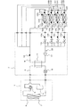
図1は、本発明の実施の形態1における空気調和装置のシステム構成を示す冷媒回路図である。
空気調和装置は、冷媒回路Aと、負荷回路Bとを備えている。冷媒回路Aは、圧縮機4と、四方弁5と、室外熱交換器6と、絞り装置8と負荷側熱交換器9とを順次配管で接続して熱源側冷媒が循環するように構成されている。負荷回路Bは、媒体搬送装置としてのポンプ10と、負荷側熱交換器9と、室内熱交換器12A、12B、12C、12D(以下、総称するときには単に「室内熱交換器12」と呼ぶ)と、流量調整弁11A、11B、11C、11D(以下、総称するときには単に「流量調整弁11」と呼ぶ)とを順次配管で接続して負荷側冷媒が循環するように構成されている。
FIG. 1 is a refrigerant circuit diagram illustrating a system configuration of the air-conditioning apparatus according to
The air conditioner includes a refrigerant circuit A and a load circuit B. The refrigerant circuit A is configured such that the
負荷回路Bでは、ポンプ10によって搬送された負荷側冷媒を、負荷側熱交換器9に流通させた後、複数経路に分岐し、分岐した各負荷側冷媒のそれぞれを、各室内熱交換器12及び各流量調整弁11に通過させた後、合流してポンプ10に戻る流路が構成されている。
In the load circuit B, the load-side refrigerant transported by the
空気調和装置は、冷媒回路Aの熱源側冷媒と負荷回路Bの負荷側冷媒とを負荷側熱交換器9で熱交換させることにより、負荷回路Bの負荷側冷媒を加熱又は冷却して室内熱交換器12に供給し、室内熱交換器12で室内空気と熱交換させることで、室内を暖房又は冷房する。冷媒回路Aには熱源側冷媒として例えばフロンやCO2 などの自然冷媒が循環し、負荷回路Bには負荷側冷媒として例えば水やブラインが循環する。以下では、負荷側冷媒として水を用いるものとして説明する。
The air conditioner heats or cools the load-side refrigerant of the load circuit B by causing the load-side heat exchanger 9 to exchange heat with the heat-source-side refrigerant of the refrigerant circuit A and the load-side refrigerant of the load circuit B, so that the indoor heat The room is heated or cooled by supplying the heat to the
そして、圧縮機4、四方弁5、室外熱交換器6及び室外熱交換器6に室外空気を送風する室外ユニット送風機7が室外ユニット1に配置されている。また、絞り装置8、負荷側熱交換器9、ポンプ10、流量調整弁11が分流コントローラー2に配置されている。また、室内熱交換器12A、12B、12C、12D及び室内熱交換器12A、12B、12C、12Dに室内空気を送風する室内ユニット送風機13A、13B、13C、13D(以下、総称するときには単に「室内ユニット送風機13」と呼ぶ)が室内ユニット3A、3B、3C、3D(以下、総称するときには単に「室内ユニット3」と呼ぶ)に配置されている。
An
分流コントローラー2は、各室内ユニット3からの水が流入する入口側に、各室内ユニット3に対応した各分岐経路を有し、各分岐経路上にそれぞれ流量調整弁11が設けられている。また、分流コントローラー2において、各室内ユニット3へ水を流出する出口側も、各室内ユニット3に対応した各分岐経路を有し、出口側の各分岐経路から流出した水が、それぞれ対応の室内ユニット3を通過した後、入口側の各分岐経路に流入し、対応の流量調整弁11を通過した後、合流し、ポンプ10に吸入される。なお、分流コントローラー2において前記入口側の各分岐経路と前記出口側の各分岐経路との間は、ポンプ10及び負荷側熱交換器9を有する主経路で接続されている。
The
(センサ類)
次に、空気調和装置に備えられたセンサ類について説明する。
分流コントローラー2は、負荷側熱交換器9で熱交換後の循環水の温度又は後述の空気抜き運転時のポンプ10の吐出温度Toutを検出する吐出温度検知器14と、温度検知器15A、15B、15C、15D(以下、総称するときには単に「温度検知器15」と呼ぶ)とを備えている。温度検知器15は、流量調整弁11を備えた各分岐経路のそれぞれに設置され、流量調整弁11に流入する循環水の温度を検知する。
(Sensors)
Next, sensors provided in the air conditioner will be described.
The
室内ユニット3A、3B、3C、3Dは、室内熱交換器12A、12B、12C、12Dの配管入口温度TAinを検知する配管入口温度検知器16A、16B、16C、16D(以下、総称するときには単に「配管入口温度検知器16」と呼ぶ)と、室内熱交換器12A、12B、12C、12Dの配管出口温度TAoutを検知する配管出口温度検知器17A、17B、17C、17D(以下、総称するときには単に「配管出口温度検知器17」と呼ぶ)とを備えている。室内ユニット3A、3B、3C、3Dは更に、室内ユニット3A、3B、3C、3Dの吸込空気温度TA0を検知する吸込空気温度検知器18A、18B、18C、18D(以下、総称するときには単に「吸込空気温度検知器18」と呼ぶ)とを備えている。
The
(制御系)
図2は、図1の空気調和装置の制御系の接続構成を示す図である。
図2に示すように、室外ユニット1には制御装置20が設置され、分流コントローラー2には制御装置21が設置されている。また、各室内ユニット3A、3B、3C、3Dには、それぞれ制御装置22A、22B、22C、22D(以下、総称するときには単に「制御装置22」と呼ぶ)が設置されている。これらの各制御装置20、21、22が、それぞれ通信線にて接続されることで、連動制御が行われる。また、室内ユニット3には、それぞれリモコン23A、23B、23C、23D(以下、総称するときには単に「リモコン23」と呼ぶ)が接続され、そこから運転操作が行われる。なお、制御装置20、21、22を、ここでは分けて構成したが、全てを統合した機能を有する一台の制御装置を、室外ユニット1又は分流コントローラー2に設ける構成としてもよい。
(Control system)
FIG. 2 is a diagram illustrating a connection configuration of a control system of the air-conditioning apparatus of FIG.
As shown in FIG. 2, a
次に、空気調和装置の冷凍サイクル動作について説明する。 Next, the refrigeration cycle operation of the air conditioner will be described.
(冷房運転)
冷房運転では、四方弁5が図1の実線で示される状態に切り換えられる。室外ユニット1の圧縮機4で圧縮された高温高圧のガス冷媒(フロン)は、四方弁5を通り、室外熱交換器6に流入する。室外熱交換器6に流入した冷媒は、空気との熱交換によって冷やされて液化し、室外ユニット1を流出して分流コントローラー2に流入する。分流コントローラー2に流入した冷媒は、絞り装置8にて減圧され、負荷側熱交換器9に流入する。負荷側熱交換器9に流入した冷媒は、負荷回路B側の循環水と熱交換し、すなわち循環水から吸熱して蒸発ガス化し、分流コントローラー2から流出する。分流コントローラー2から流出した冷媒は、室外ユニット1に再び流入し、四方弁5を経て圧縮機4に戻る流れとなる。
(Cooling operation)
In the cooling operation, the four-
一方、負荷回路Bでは、ポンプ10によって水が負荷側熱交換器9に供給され、冷媒回路Aの冷媒と熱交換して冷却され、その後、各分岐経路に分岐される。分岐した各水は、分流コントローラー2を流出して、対応の各室内ユニット3の各室内熱交換器12に流入する。各室内熱交換器12に流入した循環水は室内空気と熱交換して室内を冷房する。各室内熱交換器12で熱交換後の循環水は、各室内ユニット3を流出して再び分流コントローラー2に流入し、対応の流量調整弁11を経た後、合流し、ポンプ10に吸入される。
On the other hand, in the load circuit B, water is supplied to the load-side heat exchanger 9 by the
(暖房運転)
暖房運転では、四方弁5が図1の点線で示される状態に切り換えられる。室外ユニット1の圧縮機4で圧縮された高温高圧のガス冷媒(フロン)は、四方弁5を通った後、室外ユニット1から流出して分流コントローラー2の負荷側熱交換器9に流入する。負荷側熱交換器9に流入した冷媒は、負荷回路B側の循環水と熱交換し、すなわち循環水に放熱して凝縮液化して高圧の液冷媒となり、絞り装置8にて減圧され、分流コントローラー2から流出して再び室外ユニット1に流入する。室外ユニット1に流入した冷媒は、室外熱交換器6と熱交換して蒸発ガス化し、四方弁5を経て圧縮機4に戻る流れとなる。
(Heating operation)
In the heating operation, the four-
一方、負荷回路Bでは、ポンプ10によって水が負荷側熱交換器9に供給され、冷媒回路Aの冷媒と熱交換して加熱され、その後、各分岐経路に分岐される。分岐した各水は、分流コントローラー2を流出して、対応の各室内ユニット3の各室内熱交換器12に流入する。各室内熱交換器12に流入した循環水は室内空気と熱交換して室内を暖房する。各室内熱交換器12で熱交換後の循環水は、各室内ユニット3を流出して再び分流コントローラー2に流入し、対応の流量調整弁11を経た後、合流し、ポンプ10に吸入される。
On the other hand, in the load circuit B, water is supplied to the load-side heat exchanger 9 by the
次に、空気調和装置の据付工事の工程について説明する。据付工事の際には、まず、空気調和装置を構成する各機器を建物に設置し、その後、冷媒回路Aに熱源側冷媒を充填すると共に、負荷回路Bに循環水を注入する。負荷回路Bに循環水を注入する初期段階では、負荷回路Bを構成する水配管の内部に空気が入っているため、循環水を注入しながら水配管内の空気を外部に抜いている。この空気抜き作業を行う運転は、全ての室内ユニット3で一斉に行われ、具体的には、各室内ユニット3に設けた空気抜き弁24A、24B、24C、24D(以下、総称するときには単に「空気抜き弁24」と呼ぶ)を開いた状態で、分流コントローラー2においてポンプ10の入口側に設けた循環水注入口25から循環水を注入する。
Next, the process of installing the air conditioner will be described. At the time of installation work, first, each device constituting the air conditioner is installed in a building, and then the refrigerant circuit A is filled with the heat source side refrigerant and the circulating water is injected into the load circuit B. At the initial stage of injecting the circulating water into the load circuit B, since the air is contained in the water pipe constituting the load circuit B, the air in the water pipe is drawn outside while injecting the circulating water. The operation for performing the air venting operation is performed at the same time in all the
循環水注入口25から注入された循環水は、負荷側熱交換器9→室内熱交換器12→流量調整弁11の順で負荷回路B内を進む。そして、注入が進んでやがて空気抜き弁24から水が溢れてくると、その部位の空気抜き弁24を閉め、その他の全ての部位の空気抜き弁24も同様に閉めることで空気抜き運転が完了する。なお、空気抜き弁24は、分流コントローラー2側に設けても良い。
The circulating water injected from the circulating
空気抜き運転中は、主たる運転は分流コントローラー2で行い、室外ユニット1及び室内ユニット3は停止状態とする。よって、負荷側熱交換器9では熱交換は行われず、負荷回路Bの循環水はそのまま負荷側熱交換器9を通過することになる。また、空気抜き運転中は、室外ユニット送風機7及び室内ユニット送風機13は運転しないが、制御装置20、21、22は起動しているため、各温度検知器14、15、16、17、18で検知された温度は、制御装置21、22にて把握できるようになっている。
During the air venting operation, the main operation is performed by the
(誤接続検知原理)
次に、配管の誤接続検知原理について説明する。一般的に空気の温度と循環水の温度とは同一ではない。このため、循環水が、ある温度検知器の設置箇所に到達すると、それまで検知していた温度が、空気温度から循環水温度に変わるため、検知温度に変化が生じる。よって、その温度変化により循環水がその温度検知器の設置場所に到達したことを検知することができる。本実施の形態1では、このような循環水の到達による温度変化を利用して、誤配管接続を検出する。なお、室内熱交換器12の入口から流入した循環水が、室内熱交換器12の出口から流出するまでの時間は、標準的な空調運転時で約5秒程度で、空気抜き運転時は、約10秒程度である。よって、温度検知器のサンプリング時間を1秒としても十分にその変化を検知することができる。なお、一般的には循環水の温度の方が空気温度よりも低いため、以下の説明では、循環水の到達によって検知温度が下がるものとして説明する。
(Incorrect connection detection principle)
Next, the principle of detection of erroneous pipe connection will be described. Generally, the temperature of air and the temperature of circulating water are not the same. For this reason, when circulating water reaches the installation location of a certain temperature detector, the detected temperature changes from the air temperature to the circulating water temperature, so that the detected temperature changes. Therefore, it can be detected that the circulating water has reached the installation location of the temperature detector by the temperature change. In the first embodiment, the erroneous pipe connection is detected using such a temperature change caused by the arrival of the circulating water. In addition, the time until the circulating water flowing in from the inlet of the
図3は、本発明の実施の形態1における配管の温度変化図である。図3には、配管入口温度検知器16により検知された配管入口温度TAinと、配管出口温度検知器17により検知された配管出口温度TAoutとのそれぞれのサンプリング時間毎の検知結果を示している。図3において横軸は時間(s)、縦軸は温度(℃)である。図3において点線は配管入口温度TAinを示し、実線は配管出口温度TAoutを示している。また、図4は、図1の空気調和装置において室内ユニット3Aの入口と出口が誤接続された状態を示す図である。
FIG. 3 is a temperature change diagram of the piping in the first embodiment of the present invention. FIG. 3 shows the detection results for each sampling time of the pipe inlet temperature TAin detected by the pipe
図3では、検知開始から8秒までは配管入口温度TAinと配管出口温度TAoutとが同じであるが、8秒のときに配管入口温度TAinのみが低下している。よって、この時点で室内熱交換器12の入口に循環水が到達したことが分かる。そして、その後、18秒付近で配管出口温度TAoutも低下している。よって、この時点で室内熱交換器12の出口にも循環水が到達したことが分かる。つまり、配管入口温度TAinが所定温度(例えば3℃)以上、変化した後、所定時間(例えば30秒)以内に配管出口温度TAoutが配管入口温度TAinと同様に所定温度(例えば3℃)以上、変化した場合には、その室内ユニット3の入口と出口は正常に接続されていると判断できる。
In FIG. 3, the pipe inlet temperature TAin and the pipe outlet temperature TAout are the same from the start of detection to 8 seconds, but only the pipe inlet temperature TAin is lowered at 8 seconds. Therefore, it can be seen that the circulating water has reached the inlet of the
一方、図4に示すように、室内ユニット3の入口と出口が逆に接続されていた場合、上記のような温度変化とはならない。つまり、上記とは全く逆の温度変化が生じることになる。すなわち、配管入口温度TAinよりも、配管出口温度TAoutの方が先に温度が下がり、その後、配管入口温度TAinの温度が下がることになる。よって、この温度変化の違いを検知することで、誤接続を検知することができる。
On the other hand, as shown in FIG. 4, when the inlet and outlet of the
図5は、本発明の実施の形態1における空気抜き運転時の誤接続検知処理を示すフローチャートである。この図5のフローチャートの処理は、空気抜き運転の開始と同時に開始される。
ここで、図5のフローチャートの説明をするに先立ち、ポンプ10の吐出温度Tout、配管入口温度TAin及び配管出口温度TAoutの時系列の温度変化について説明する。温度変化の概要については上述した通りであるが、ここでは、説明をわかりやすくするため、具体的な数値の一例を以て説明していくことにする。なお、ここで使用する具体的数値は一例を示したに過ぎず、それらは実使用条件等に応じて適宜設定すれば良い。この点は以下の実施の形態2において同様である。
FIG. 5 is a flowchart showing an erroneous connection detection process during the air vent operation in the first embodiment of the present invention. The process of the flowchart of FIG. 5 is started simultaneously with the start of the air bleeding operation.
Here, prior to the description of the flowchart of FIG. 5, time-series temperature changes of the discharge temperature Tout, the pipe inlet temperature TAin, and the pipe outlet temperature TAout of the
以下、図5のフローチャートの説明を、接続が正常な場合と、誤接続されている場合とに分けて説明する。なお、上述したように、空気抜き運転時において室内熱交換器12の入口から流入した循環水が出口から流出するまでの時間は、約10秒程度であり、図5のフローは、この間の短い時間内で誤配管があるかどうかを検知するフローである。
Hereinafter, the description of the flowchart of FIG. 5 will be divided into a case where the connection is normal and a case where the connection is incorrect. As described above, the time until the circulating water flowing in from the inlet of the
(接続が正常な場合)
接続が正常な場合は、Tout→TAin→TAoutの順で、温度が低下していくため、時系列の温度変化は以下のようになる。
(a)空気抜き運転開始時
Tout=TAin=TAout=25℃
(b)空気抜き運転開始直後で吐出温度検知器14の設置箇所に循環水到達した段階
Tout=15℃、TAin=TAout=25℃
(c)もう少し経過:室内熱交換器12の入口に循環水到達
Tout=10℃、TAin=15℃、TAout=25℃
(d)更に経過
Tout=10℃、TAin=12℃、TAout=20℃
(e)もっと経過
Tout=10℃、TAin=12℃、TAout=12℃
(If the connection is normal)
When the connection is normal, the temperature decreases in the order of Tout → TAin → TAout, so the time-series temperature change is as follows.
(A) At the start of air venting operation Tout = TAin = TAout = 25 ° C.
(B) The stage where the circulating water reaches the installation location of the
(C) A little longer: Circulating water reaches the inlet of the
(D) Further progress Tout = 10 ° C., TAin = 12 ° C., TAout = 20 ° C.
(E) More elapsed Tout = 10 ° C., TAin = 12 ° C., TAout = 12 ° C.
(接続が正常な場合の処理の流れ)
図5のフローでは、まず、FLG=0にする(S1)。そして、空気抜き運転開始から30分以内か否かを判断(S2)し、ここではYに進み、続いてFLGが0であるかを判断する(S3)。ここではFLG=0であるため、Yに進み、続いてポンプ10の吐出温度Toutと室内ユニット3の配管出口温度TAoutとの温度差が3℃以上で、且つ吐出温度Toutの方が低いかどうかを判断する(S4)。このS3は、循環水注入口25から注入された循環水が吐出温度検知器14の設置箇所に到達したかを検知するための判断である。
(Processing flow when connection is normal)
In the flow of FIG. 5, first, FLG = 0 is set (S1). Then, it is determined whether or not it is within 30 minutes from the start of the air bleeding operation (S2). Here, the process proceeds to Y, and subsequently it is determined whether FLG is 0 (S3). Here, since FLG = 0, the process proceeds to Y. Subsequently, whether or not the temperature difference between the discharge temperature Tout of the
上記(a)のように空気抜き運転開始時等、循環水注入口25から注入された循環水が吐出温度検知器14の設置箇所に到達するまでの間は、吐出温度Toutと室内ユニット3の配管出口温度TAoutとは同じ温度であり、温度差は0である。このため、S4の判断ではNに進み、S2に戻って同様の処理を繰り返す。そして、循環水注入口25から注入された循環水が吐出温度検知器14の設置箇所に到達すると、上記(b)のように吐出温度Toutの温度が下がり、配管出口温度TAoutとの温度差が広がっていく。そして、その温度差が3℃以上となると、循環水が吐出温度検知器14の設置箇所に確実に到達したものと判断し、FLG=1にして(S5)、S2に戻る。
The discharge temperature Tout and the piping of the
そして、S2でY→S3でNと進み、FLGが1であるか否かを判断する(S6)。ここではFLGは1であるため、Yに進み、続いて室内ユニット3の配管入口温度TAinと配管出口温度TAoutとの温度差の絶対値が1℃以内であるかを判断する(S7)。空気抜き運転開始直後(注入開始直後)は、上記(b)のように、配管入口温度TAinと配管出口温度TAoutとの温度差は0℃であるため、S7でYに進み、FLG=2とし(S8)、S2に戻る。
Then, the process proceeds from Y in S2 to N in S3, and it is determined whether or not FLG is 1 (S6). Here, since FLG is 1, the process proceeds to Y, and then it is determined whether the absolute value of the temperature difference between the pipe inlet temperature TAin and the pipe outlet temperature TAout of the
そして、S2でY→S3でN→S6でNと進み、FLGが2であるか否かを判断する(S9)。ここではFLGは2であるため、Yに進み、続いて配管入口温度TAinと配管出口温度TAoutとの温度差が3℃以上あり、且つ配管入口温度TAinの方が低いかどうかを判断する(S10)。現時点では上述したように温度差は0℃であるため、S10でNに進み、続いて配管入口温度TAinと配管出口温度TAoutとの温度差が3℃を超え、且つ配管入口温度TAinの方が高いかどうかを判断する(S11)。ここでは、温度差は0℃であるため、S11でNに進み、「循環水が室内熱交換器12に到達する途中」と判断して(S12)、S2に戻る。
Then, in S2, Y → S3, N → S6, N, and it is determined whether FLG is 2 (S9). Here, since FLG is 2, the process proceeds to Y, and subsequently, it is determined whether the temperature difference between the pipe inlet temperature TAin and the pipe outlet temperature TAout is 3 ° C. or more and the pipe inlet temperature TAin is lower (S10). ). Since the temperature difference is currently 0 ° C. as described above, the process proceeds to N in S10. Subsequently, the temperature difference between the pipe inlet temperature TAin and the pipe outlet temperature TAout exceeds 3 ° C., and the pipe inlet temperature TAin is greater. It is determined whether it is high (S11). Here, since the temperature difference is 0 ° C., the process proceeds to N in S11, determines that “the circulating water reaches the
S2に戻って以降、配管入口温度TAinが配管出口温度TAoutよりも3℃以上、下がるまでの間(つまり、S10でYとなるまでの間)は、S2でY→S3でN→S6でN→S9でY→S10でN→S11でN→S2の循環水到達途中ループが継続される。 After returning to S2, until the pipe inlet temperature TAin drops by 3 ° C. or more from the pipe outlet temperature TAout (that is, until it becomes Y in S10), Y in S2 → N in S3 → N in S6 → Y in S9 → N in S10 → N → S11 and N → S2 The circulating water reaching loop is continued.
そして、もう少し経過して、循環水が室内熱交換器12の入口に到達すると、上記(c)に示すように、配管入口温度TAinが25℃から15℃に下がる一方、室内熱交換器12の出口にはまだ到達していないため、配管出口温度TAoutは25℃のままとなる。このように、配管入口温度TAinが、配管出口温度TAoutよりも3℃以上、下がると、「循環水が室内熱交換器12に到達した」と判断し、循環水到達途中ループを抜けて、S10の判断でYに進み、FLG=3にして(S13)、S2に戻る。
Then, when a little more has passed and the circulating water reaches the inlet of the
そして、S2でY→S3でN→S6でN→S9でNと進み、FLGが3であるか否かを判断する(S14)。ここではFLGは3であるため、Yに進み、続いて配管入口温度TAinと配管出口温度TAoutとの温度差の絶対値が1℃以下であるかを判断する(S15)。上記(c)の段階では、温度差が10℃であるため、S15でNに進み、S2に戻る。 Then, in S2, Y → S3, N → S6, N → S9, N, and it is determined whether FLG is 3 (S14). Here, since FLG is 3, the process proceeds to Y, and then it is determined whether the absolute value of the temperature difference between the pipe inlet temperature TAin and the pipe outlet temperature TAout is 1 ° C. or less (S15). In the stage (c), since the temperature difference is 10 ° C., the process proceeds to N in S15 and returns to S2.
S2に戻って以降、配管入口温度TAinと配管出口温度TAoutとの温度差が1℃以下となるまで、S2でY→S3でN→S6でN→S9でN→S14でY→S15でN→S2の循環水到達後ループが継続される。 After returning to S2, until the temperature difference between the pipe inlet temperature TAin and the pipe outlet temperature TAout becomes 1 ° C. or less, Y → S3 at N → S6 at N → S6 at N → S9 at N → S14 at Y → S15 at N → The loop is continued after reaching the circulating water in S2.
ここで、循環水到達後ループについて説明する。正常に接続されていれば、注入が進むにつれ、配管入口温度TAinは循環水の温度まで徐々に下がっていく。そして、配管出口温度検知器17Aの設置箇所、つまり室内熱交換器12の出口に循環水が到達すると、配管出口温度TAoutも下がり始め、循環水の温度まで徐々に下がっていく。よって、配管入口温度TAinと配管出口温度TAoutのそれぞれの温度は、両方共、循環水の温度に近づいて行くため、互いの温度差は縮まっていくことになる。したがって、循環水到達後ループでは、配管入口温度TAinと配管出口温度TAoutとの温度差が1℃以下まで縮んだか否かを判断するようにしている。
Here, the loop after reaching the circulating water will be described. If the connection is normal, the pipe inlet temperature TAin gradually decreases to the temperature of the circulating water as the injection proceeds. When the circulating water reaches the installation location of the pipe
上記(c)の段階では、配管入口温度TAinと配管出口温度TAoutとの温度差が10℃であるが、上記(d)の段階では8℃と縮まっており、上記(e)の段階では、温度差0となっている。よって、このように温度差が1℃以下となると、循環水到達後ループを抜け、「誤接続なし」と判断(R1)して、誤接続検知処理を終了する。 In the stage (c), the temperature difference between the pipe inlet temperature TAin and the pipe outlet temperature TAout is 10 ° C., but in the stage (d), the temperature difference is reduced to 8 ° C. In the stage (e), The temperature difference is zero. Therefore, when the temperature difference becomes 1 ° C. or less in this way, the loop exits after reaching the circulating water, determines that there is no erroneous connection (R1), and ends the erroneous connection detection process.
(誤接続の場合)
次に、誤接続の場合について説明する。図4に示したように誤接続されている場合、時系列の温度変化は、配管入口温度TAinと配管出口温度TAoutとの温度変化が、正常接続の場合と逆になり、以下のようになる。
(A)空気抜き運転開始時
Tout=TAin=TAout=25℃
(B)空気抜き運転開始直後で吐出温度検知器14の設置箇所に循環水到達した段階
Tout=15℃、TAin=TAout=25℃
(C)もう少し経過:室内熱交換器12の出口側に循環水到達
Tout=10℃、TAin=25℃、TAout=15℃
(D)更に経過
Tout=10℃、TAin=20℃、TAout=12℃
(E)もっと経過
Tout=10℃、TAin=12℃、TAout=12℃
(In case of incorrect connection)
Next, the case of incorrect connection will be described. In the case of incorrect connection as shown in FIG. 4, the time-series temperature change is as follows when the temperature change between the pipe inlet temperature TAin and the pipe outlet temperature TAout is opposite to the normal connection. .
(A) At the start of air venting operation Tout = TAin = TAout = 25 ° C
(B) The stage where the circulating water reaches the installation location of the
(C) A little longer: Circulating water reaches the outlet side of the
(D) Further progress Tout = 10 ° C., TAin = 20 ° C., TAout = 12 ° C.
(E) More progress Tout = 10 ° C., TAin = 12 ° C., TAout = 12 ° C.
(誤接続の場合の処理の流れ)
図5のフローでは、まず、FLG=0にする(S1)。そして、空気抜き作業開始から30分以内か否かを判断(S2)し、ここではYに進み、続いてFLGが0であるかを判断する(S3)。ここではFLG=0であるため、Yに進み、続いてポンプ10の吐出温度Toutと室内ユニット3の配管出口温度TAoutとの温度差が3℃以上で、且つ吐出温度Toutの方が低いかどうかを判断する(S4)。
(Processing flow for incorrect connection)
In the flow of FIG. 5, first, FLG = 0 is set (S1). Then, it is determined whether or not it is within 30 minutes from the start of the air venting operation (S2). Here, the process proceeds to Y, and subsequently it is determined whether FLG is 0 (S3). Here, since FLG = 0, the process proceeds to Y. Subsequently, whether or not the temperature difference between the discharge temperature Tout of the
上記(A)のように空気抜き運転開始時等、循環水注入口25から注入された循環水が吐出温度検知器14の設置箇所に到達するまでの間は、吐出温度Toutと室内ユニット3の配管出口温度TAoutとは同じ温度であり、温度差は0である。このため、S4の判断ではNに進み、S2に戻って同様の処理を繰り返す。そして、循環水注入口25から注入された循環水が吐出温度検知器14の設置箇所に到達すると、上記(b)のように吐出温度Toutの温度が下がり、配管出口温度TAoutとの温度差が広がっていく。そして、その温度差が3℃以上となると、循環水が吐出温度検知器14の設置箇所に確実に到達したものと判断し、FLG=1にして(S5)、S2に戻る。
The discharge temperature Tout and the piping of the
そして、S2でY→S3でN→S6でYと進み、続いて室内ユニット3の配管入口温度TAinと配管出口温度TAoutとの温度差の絶対値が1℃以内であるかを判断する(S7)。空気抜き運転開始直後(注入開始直後)は、上記(B)のように、配管入口温度TAinと配管出口温度TAoutとの温度差は0℃であるため、S7でYに進み、FLG=2とし(S8)、S2に戻る。そして、S2でY→S3でN→S6でN→S9でYに進む。
Then, in S2, Y → S3, N → S6, Y, and then it is determined whether the absolute value of the temperature difference between the pipe inlet temperature TAin and the pipe outlet temperature TAout of the
そして、配管入口温度TAinと配管出口温度TAoutとの温度差が3℃以上あり、且つ配管入口温度TAinの方が低い温度であるかどうかを判断する(S10)。誤接続が生じていても、上記(B)の段階では、配管入口温度TAinと配管出口温度TAoutとは同じ温度であり、温度差は0℃であるため、S10でN→S11でNとなり、「循環水が室内熱交換器12に到達する途中」と判断して(S12)、S2に戻る。
Then, it is determined whether or not the temperature difference between the pipe inlet temperature TAin and the pipe outlet temperature TAout is 3 ° C. or more and the pipe inlet temperature TAin is lower (S10). Even if an erroneous connection has occurred, at the stage of (B), the pipe inlet temperature TAin and the pipe outlet temperature TAout are the same temperature, and the temperature difference is 0 ° C. Therefore, N in S10 becomes N in S11, It is determined that “the circulating water is reaching the
S2に戻って以降、S2でY→S3でN→S6でN→S9でY→S10でN→S11でN→S2の循環水到達途中ループが継続される。 After returning to S2, the circulating water arrival loop of Y → S3, N → S6, N → S9, Y → S10, N → S11, N → S2 is continued in S2.
ここでは、室内熱交換器12の入口と出口が間違って接続されているため、循環水は室内熱交換器12の入口側よりも出口側に先に到達する。よって、配管入口温度TAinよりも配管出口温度TAoutが先に下がり、上記(C)に示すように、配管出口温度TAoutが25℃から15℃に下がる。一方で室内熱交換器12の入口にはまだ到達していないため、配管入口温度TAinは25℃のままとなる。このような温度関係となると、S11の判断でYとなり、循環水到達途中ループを抜けて、「入口・出口誤配管接続」と判断し、FLG=4にして(S16)、S2に戻る。
Here, since the inlet and outlet of the
そして、S2でY→S3でN→S6でN→S9でN→S14でNと進み、続いて配管入口温度TAinと配管出口温度TAoutとの温度差の絶対値が1℃以内であるかを判断する(S17)。上記(C)、(D)のように、注入開始からしばらくの間は、配管入口温度TAinと配管出口温度TAoutとの温度差の絶対値が1℃よりも大きい状態が続くため、S17でN→S2でY→S3でN→S6でN→S9でN→S14でN→S17でNのループが続くが、注入が進むと、正常接続の場合と同様に、その温度差の絶対値が縮まり始め、最終的には上記(E)に示すように同じ温度となる。よって、S17でYに進み「異常発報(誤接続)」を行い(R2)、誤接続検知処理を終了する。 Then, in S2, Y → S3, N → S6, N → S9, N → S14, and N, and then whether the absolute value of the temperature difference between the pipe inlet temperature TAin and the pipe outlet temperature TAout is within 1 ° C. Judgment is made (S17). As in (C) and (D) above, since the absolute value of the temperature difference between the pipe inlet temperature TAin and the pipe outlet temperature TAout continues to be greater than 1 ° C. for a while after the start of injection, N in S17. → Y in S2, N in S3, N → S6, N → S9, N → S14, N → S17, N loop continues, but as the injection proceeds, the absolute value of the temperature difference is the same as in normal connection It starts to shrink and finally reaches the same temperature as shown in (E) above. Therefore, the process proceeds to Y in S17, "abnormal issue (incorrect connection)" is performed (R2), and the erroneous connection detection process is terminated.
以上の説明から明かなように、誤接続時の温度変化は、室内熱交換器12の配管入口温度TAinと配管出口温度TAoutとの温度差が、空気抜き運転の開始初期の段階で第1所定値(上記では1℃)以下と小さく、その後、配管の誤接続により、循環水が室内熱交換器12の出口側に先に到達し、配管出口温度TAoutの方が、第2所定値(第1所定値よりも大きい温度で、上記では3℃)以上、配管入口温度TAinよりも低くなり、更にその後、循環水が室内熱交換器12の入口にも到達して前記温度差が狭まっていき、第3所定値(第2所定値よりも小さい温度で、上記では1℃)以下となる。よって、このような温度変化を辿る場合、誤接続と判断することができる。
As is clear from the above description, the temperature change at the time of incorrect connection is that the temperature difference between the pipe inlet temperature TAin and the pipe outlet temperature TAout of the
なお、誤接続検知処理を開始してから、吐出温度検知器14の設置箇所への循環水の到達が認められ(つまりFLG=1)、且つ配管入口温度TAinと配管出口温度TAoutとの温度差の絶対値が1℃を超える状態(S7でN、S15でN、S17でN)が30分を超えた場合は、「誤接続判定不能」と判断して(R3)、誤接続検知処理を終了する。
In addition, after the erroneous connection detection process is started, the arrival of the circulating water at the installation location of the
以上説明したように、本実施の形態1によれば、室内熱交換器12の入口と出口にそれぞれ配置した配管入口温度検知器16と配管出口温度検知器17との時系列の温度変化により、負荷回路Bの配管施工時の誤接続を容易に検知することができる。
As described above, according to the first embodiment, due to the time-series temperature changes of the pipe
実施の形態2.
上記実施の形態1では、室内ユニット1台の中での入口と出口の配管の誤接続を検知するものであったが、実施の形態2では、更に、室内ユニット3間の誤接続を検知するものである。
In the first embodiment, the erroneous connection between the inlet and outlet pipes in one indoor unit is detected. However, in the second embodiment, the erroneous connection between the
実施の形態2の空気調和装置の構成は図1に示した実施の形態1と同様である。以下では、実施の形態2が実施の形態1と異なる部分を中心に説明する。
The structure of the air conditioning apparatus of
図6は、本発明の実施の形態2において室内ユニット間で誤接続された状態を示す図である。
図6には、室内ユニット3間の誤接続の一例として、室内ユニット3Aと室内ユニット3Bとが逆に接続された状態を示している。このように逆に接続されていると、本来流量調整弁11Aの開度調整により室内熱交換器12Aの流量を制御できるはずが、室内熱交換器12Bの流量が制御されてしまうことになる。よって、このような室内ユニット3間の誤接続の検知は重要であり、実施の形態2では、冷房又は暖房の試運転で室内ユニット3を一台ずつ動作させて室内ユニット3間の誤接続を検知する。なお、実施の形態2の空気調和装置は、室内ユニット間の誤接続だけでなく、実施の形態1と同様に室内ユニット1台の中での入口と出口の誤接続検知も可能である。
FIG. 6 is a diagram showing a state in which the indoor units are erroneously connected in the second embodiment of the present invention.
FIG. 6 shows a state in which the
以下、室内ユニット3間の誤接続の検知原理について説明する。ここでは、冷房運転による試運転の場合について説明する。ここでは室内ユニット3Aを動作させて室内ユニット3Aに誤接続があるかを検知する例で説明する。この場合、分流コントローラー2の制御装置21は、分流コントローラー2内の吐出温度検知器14により検知された吐出温度Toutと、室内ユニット3A内の配管入口温度検知器16Aにより検知された配管入口温度TAinと、配管出口温度検知器17Aにより検知された配管出口温度TAoutとを用いて、誤接続検知を行う。
Hereinafter, the detection principle of the erroneous connection between the
なお、以下では、室内ユニット3A内の配管入口温度検知器16Aにより検知された配管入口温度TAinを配管入口温度TAin(A)と呼び、配管出口温度検知器17Aにより検知された配管出口温度TAoutを配管出口温度TAout(A)と呼ぶ。また、室内ユニット3A内の吸込空気温度検知器18Aにより検知された吸込空気温度TA0を吸込空気温度TA0(A)と呼ぶ。なお、室内ユニット3B、3C、3Dについても同様の呼び方とし、室内ユニット3Bであれば、配管入口温度TAin(B)、配管出口温度TAout(B)、吸込空気温度TA0(B)とする。
Hereinafter, the pipe inlet temperature TAin detected by the pipe
冷房運転では、上述したように負荷回路Bの循環水が冷媒回路A側の熱源側冷媒と負荷側熱交換器9で熱交換して冷却される。よって、負荷回路Bの循環水の温度は時間の経過と共に下がっていく。水温が下がると、室内ユニット3Aが正しく接続されていれば、配管入口温度TAin(A)が下がるため、配管入口温度TAin(A)と、吸込空気温度TA0(A)との温度差が徐々に大きくなっていくはずである。よって、配管入口温度TAin(A)と吸込空気温度TA0(A)との温度差をチェックすることにより、まず、正常に接続されているか否かを切り分けることができる。
In the cooling operation, the circulating water in the load circuit B is cooled by exchanging heat with the heat source side refrigerant on the refrigerant circuit A side and the load side heat exchanger 9 as described above. Therefore, the temperature of the circulating water in the load circuit B decreases with time. When the water temperature decreases, if the
そして、正常に接続されていない場合に、室内ユニット間の誤接続が有るかどうかを、配管入口温度TAin(A)と配管出口温度TAout(A)との温度差を用いて判断する。以下、この点について説明する。 And when not connected normally, it is judged using the temperature difference of piping inlet_port | entrance temperature TAin (A) and piping outlet temperature TAout (A) whether there exists an incorrect connection between indoor units. Hereinafter, this point will be described.
制御装置21からの制御信号で室内ユニット3Aの室内ユニット送風機13Aを駆動すると、室内ユニット3Aが正常に接続されている場合には、室内熱交換器12Aを通過する循環水と吸込空気とが熱交換され、循環水の温度が上昇し、配管入口温度TAin(A)と配管出口温度TAout(A)との温度差が生じる。一方、図6のように誤接続されている場合、室内ユニット3Aの室内熱交換器12Aには循環水が通過していないため、室内ユニット送風機13Aを駆動しても、室内熱交換器12Aで熱交換が行われず、配管入口温度検知器16Aで検知された配管入口温度TAin(A)と配管出口温度検知器17Aで検知された配管出口温度TAout(A)との温度差には変化が生じない。よって、これを利用して誤接続を検知できる。
When the
配管入口温度TAin(A)と配管出口温度TAout(A)との温度差は、循環水の流量を少量とすることでも生じる。すなわち、室内熱交換器12Aを通過する循環水の量を少なくすると、室内熱交換器12Aでの室内空気との熱交換後の循環水の温度が、循環水の量を多くした場合に比べて高くなる。よって、配管入口温度TAin(A)と配管出口温度TAout(A)との温度差が大きくなる。したがって、正常に接続されていれば、分流コントローラー2において室内ユニット3Aに対応する流量調整弁11Aの開度を小さくして流量を少量とすると、配管入口温度TAin(A)と配管出口温度TAout(A)との温度差が大きくなる。しかし、図6のように誤接続されていると、流量調整弁11Aを絞っても、そもそも室内熱交換器12Aには循環水が通っていないため、配管入口温度TAin(A)と配管出口温度TAout(A)との温度差には変化が生じない。よって、これを利用して誤接続を検知できる。
The temperature difference between the pipe inlet temperature TAin (A) and the pipe outlet temperature TAout (A) is also caused by reducing the flow rate of the circulating water. That is, if the amount of circulating water passing through the
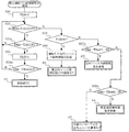
図7は、本発明の実施の形態2における室内ユニット間の誤接続検知処理を示すフローチャートである。なお、図7は冷房運転時のフローを示している。なお、ここでは、室内ユニット3A、3B、3C、3Dの順で動作させて誤接続を検知するものとして説明する。
まず、室内ユニット3Aに対応する流量調整弁11Aを予め設定した所定開度に開く。ここでの所定開度は、上述したように流量を少量とするための開度であり、通常の冷房運転時の開度(この開度は、所定の冷房能力を発揮するために吐出温度検知器14で検知された温度と温度検知器15で検知された開度との差温が所定値になるように流量調整されたときの開度である。)(暖房運転時の誤接続検知の場合は、通常の暖房運転時の開度)よりも小さい開度とする。流量調整弁11A以外の流量調整弁11B、11C、11Dは閉じる。このように流量調整弁11Aを開いてポンプ10を作動させることにより、正常に接続されていれば、ポンプ10→負荷側熱交換器9→室内熱交換器12A→流量調整弁11Aの順に水が循環する。また、室内ユニット送風機13Aを駆動し、室外ユニット1の圧縮機4を駆動して冷媒回路A内に熱源側冷媒を循環させ、まず、室内ユニット3Aの冷房運転を開始する。以下、室内ユニット3Aの冷房運転を開始して以降の図7のフローの流れを、接続が正常な場合と誤接続の場合とに分けて説明する。
FIG. 7 is a flowchart showing an erroneous connection detection process between indoor units in
First, the flow
(接続が正常な場合)
まず、接続が正常な場合について説明する。冷房運転を開始してまず、FLG=0にし(S20)、開始から所定時間(例えば30分)以内かを判断(S21)し、ここではYに進み、続いて吸込空気温度TA0(A)と配管入口温度TAin(A)との温度差が5℃(第1所定値)以上か否かを判断する(S22)。運転開始時は吸込空気温度TA0(A)と配管入口温度TAin(A)との温度差は小さいため、S22でN→S21でY→S22のループが繰り返される。そして、正常に接続されている場合は、上述したように吸込空気温度TA0(A)と配管入口温度TAin(A)との温度差が広がっていくため、5℃以上となると、FLG=1にして(S23)、S24に進む。
(If the connection is normal)
First, a case where the connection is normal will be described. First, when the cooling operation is started, FLG = 0 is set (S20), and it is determined whether it is within a predetermined time (for example, 30 minutes) from the start (S21). Here, the process proceeds to Y, and then the intake air temperature TA0 (A) is set. It is determined whether the temperature difference from the pipe inlet temperature TAin (A) is 5 ° C. (first predetermined value) or more (S22). Since the temperature difference between the intake air temperature TA0 (A) and the pipe inlet temperature TAin (A) is small at the start of operation, the loop of N → S21 and Y → S22 is repeated in S22. If the connection is normal, the temperature difference between the intake air temperature TA0 (A) and the pipe inlet temperature TAin (A) increases as described above. (S23), the process proceeds to S24.
S24では、配管入口温度TAin(A)と配管出口温度TAout(A)との温度差が、3℃以上あるか否かを判断し(S24)、3℃以上であれば、「誤接続なし」と判断する(R1)。以上の処理を、室内ユニット3B、3C、3Dについても同様に行う。
In S24, it is determined whether or not the temperature difference between the pipe inlet temperature TAin (A) and the pipe outlet temperature TAout (A) is 3 ° C. or more (S24). (R1). The above processing is similarly performed for the
(誤接続の場合)
次に、誤接続の場合について説明する。図6に示したように室内ユニット3Aと室内ユニット3Bとが逆に接続されている場合を例に説明する。
室内ユニット3Aの冷房運転を開始してまず、FLG=0にし(S20)、開始から所定時間(例えば30分)以内かを判断(S21)し、ここではYに進み、続いてS22の判断を行う。ここでは誤接続されているため、流量調整弁11Aが所定開度で開かれていても、循環水注入口25から注水した循環水は、室内ユニット3Aには流入せず、室内ユニット3B側に流入する。このため、吸込空気温度TA0(A)と配管出口温度TAout(A)とは変化しない。よって、S22でNに進み、S22でN→S21でY→S22でNのループが続くことになる。
(In case of incorrect connection)
Next, the case of incorrect connection will be described. The case where the
When the cooling operation of the
そして、このループが冷房運転開始から30分が経過すると、FLG=0であるかを判断し(S25)、ここではFLG=0であるため、Yに進み、制御装置21は、運転中の室内ユニット3Aのアドレス等の識別情報を記憶し(S26)、「異室内ユニット間誤接続の可能性有り」と判断する(R2)。そして、分流コントローラー2の制御装置21は、室内ユニット3Aの識別情報と共に誤接続有と記憶し、次の室内ユニット3Bの動作に移行する。
Then, when 30 minutes have elapsed from the start of the cooling operation in this loop, it is determined whether FLG = 0 (S25). Here, since FLG = 0, the process proceeds to Y, and the
すなわち、流量調整弁11Aを閉め、流量調整弁11Bを所定開度に開き、流量調整弁11C、11Dは閉じたままとして室内ユニット3Bの室内ユニット送風機13Bを動作させ、図7のフローチャートの処理を行う。ここでは、室内ユニット3Aと室内ユニット3Bとが間違って接続されているため、上記の室内ユニット3Aの場合と同様に、「異室内ユニット間誤接続の可能性有り」と判断される(R2)。そして、分流コントローラー2の制御装置21は、室内ユニット3Bの動作結果として識別情報と共に誤接続有と記憶し、次の室内ユニット3C、3Dについても、順次、同様の動作を行う。そして、全室内ユニット3の動作を終えたところで、次の図8のフローチャートの処理を行う。
That is, the flow
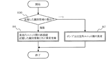
図8は、図7の続きの誤接続検知処理の流れを示すフローチャートである。
まず、分流コントローラー2の制御装置21は、記憶している識別情報の数をチェックし(S30)、複数の場合、つまり複数台の室内ユニットで「異室内ユニット間誤接続の可能性有り」と判断された場合、「異室内ユニット間の誤接続」と判断して、記憶した全ての識別情報と共に異常発報を行う(R6)。異常発報としては例えば、該当の各室内ユニット3のそれぞれのリモコン23に、誤接続有と判断した室内ユニット3のアドレスと、誤接続異常のエラーコードとを表示させたり、音声を使用して発報したりする等、任意の方法で発報すればよい。一方、記憶している識別情報の数が1つの場合は、その識別情報の室内ユニット3のポンプ10又は室外ユニット1側の異常と判断する(R7)。
FIG. 8 is a flowchart showing a flow of erroneous connection detection processing continued from FIG.
First, the
図7の説明に戻る。
吸込空気温度TA0(A)と配管入口温度TAin(A)との温度差が5℃以上あり(S22でY)、室内熱交換器12Aへの循環水の流通がみられる場合、つまり室内ユニット3間での誤接続は生じていない場合であって、30分を超えた際(S21でN)の配管出口温度TAout(A)と配管入口温度TAin(A)との温度差が5℃(第2所定値)以上で、且つ配管出口温度TAout(A)の方が低い場合は(S27のY)、室内ユニット3Aにおいて入口と出口とを誤接続していると判断して異常発報を行う(R3)。
Returning to the description of FIG.
When the temperature difference between the intake air temperature TA0 (A) and the pipe inlet temperature TAin (A) is 5 ° C. or more (Y in S22) and circulation of circulating water to the
一方、S27でNの場合、続いて吐出温度検知器14で検知された吐出温度(負荷側熱交換器9で熱交換後の循環水の温度)Toutと配管入口温度TAin(A)との温度差が5℃(第3所定値)以上で、且つ吐出温度Toutの方が低いかどうかを判断する(S28)。吐出温度Toutと配管入口温度TAin(A)との温度差が5℃以上で、且つ吐出温度Toutの方が低い場合、配管入口温度検知器16A又は吐出温度検知器14に異常があるものと判断し、異常発報を行う(R4)。吐出温度Toutと配管入口温度TAin(A)との温度差が5℃未満の場合は、冷水が循環されていないと判断し、分流コントローラー2や室外ユニット1側に何らかの異常があるものと判断する(R5)。この場合は、冷媒回路Aの圧力や温度による異常検知も行っており、配管誤接続とは異なる異常検知制御にて判定されるが、ここでは説明を省略する。
On the other hand, in the case of N in S27, the temperature between the discharge temperature detected by the discharge temperature detector 14 (the temperature of the circulating water after heat exchange in the load side heat exchanger 9) Tout and the pipe inlet temperature TAin (A). It is determined whether the difference is 5 ° C. (third predetermined value) or more and the discharge temperature Tout is lower (S28). When the temperature difference between the discharge temperature Tout and the pipe inlet temperature TAin (A) is 5 ° C. or more and the discharge temperature Tout is lower, it is determined that the pipe
また、暖房運転時の誤接続検知のフローチャートを図9に示す。図9において同一処理部分は同一ステップ番号を記す。暖房運転時では、S22a、S24a、S27a、S28aのそれぞれにおいて、不等式の左辺側の減算式において、右辺と左辺とが入れ替わってる点が異なっており、誤接続検知の基本的な内容は図7、図8の冷房運転時と同様である。 Moreover, the flowchart of the misconnection detection at the time of heating operation is shown in FIG. In FIG. 9, the same processing parts are denoted by the same step numbers. At the time of heating operation, in each of S22a, S24a, S27a, S28a, the difference between the left side and the left side of the inequality is that the right side and the left side are interchanged. This is the same as in the cooling operation of FIG.
以上説明したように本実施の形態2によれば、冷房又は暖房の試運転中の温度検知器14、16、17の検知温度の変化に基づいて室内ユニット3内での入口と出口の誤接続のみならず、異なる室内ユニット3間の誤接続、更には、配管入口温度検知器16A又は吐出温度検知器14の異常、分流コントローラー2又は室外ユニット1に異常があることを検知できる。なお、実施の形態2では、これらの誤接続や異常をまとめて検知できる構成について説明したが、少なくとも異なる室内ユニット3間の誤接続又は室内ユニット3内での入口と出口の誤接続を検知できる構成であればよい。
As described above, according to the second embodiment, only the erroneous connection between the inlet and the outlet in the
なお、流量調整弁11の開度が小さいほど、上述したように、室内熱交換器12の入口と出口の温度差が大きくなる傾向にあり、また、室内ユニット送風機13の風量が大きいほど、室内熱交換器12の入口と出口の温度差が大きくなる傾向にある。よって、最大風量で且つ流量調整弁11の開度を可能な限り小さくした状態での誤接続確認を行うことで、より確実な検査が行える。
As described above, the smaller the opening degree of the flow
また、室内熱交換器12の配管出口温度TAoutを検知する配管出口温度検知器17は、分流コントローラー2の入口温度を検知する温度検知器15に置き換えてもよい。この場合、配管出口温度検知器17の設置を無くすことができる。
The pipe outlet temperature detector 17 that detects the pipe outlet temperature TAout of the
なお、上記実施の形態1、2においてそれぞれ別の実施の形態として説明したが、実施の形態1、2を組み合わせて空気調和装置を構成してもよい。
In addition, although demonstrated as another embodiment in the said
また、冷媒回路の構成は図示のものに限定されず、例えば、四方弁を省略して冷房又は暖房の何れか一方のみが可能な構成としてもよい。また、負荷回路の構成、温度検知器の設置位置等についても、上記実施の形態1、2で説明した内容に限定されるものではなく、本発明の課題の範囲内で適宜変更可能である。 Further, the configuration of the refrigerant circuit is not limited to the illustrated one, and for example, the four-way valve may be omitted and only one of cooling and heating may be possible. Further, the configuration of the load circuit, the installation position of the temperature detector, and the like are not limited to the contents described in the first and second embodiments, and can be appropriately changed within the scope of the problem of the present invention.
1 室外ユニット、2 分流コントローラー、3、3A、3B、3C、3D 室内ユニット、4 圧縮機、5 四方弁、6 室外熱交換器、7 室外ユニット送風機、8 絞り装置、9 負荷側熱交換器、10 ポンプ、11、11A、11B、11C、11D 流量調整弁、12、12A、12B、12C、12D 室内熱交換器、13、13A、13B、13C、13D 室内ユニット送風機、14 吐出温度検知器、15、15A、15B、15C、15D 温度検知器、16、16A、16B、16C、16D 配管入口温度検知器、17、17A、17B、17C、17D 配管出口温度検知器、18、18A、18B、18C、18D 吸込空気温度検知器、20 制御装置、21 制御装置、22、22A、22B、22C、22D 制御装置、23、23A、23B、23C、23D リモコン、24、24A、24B、24C、24D 空気抜き弁、25 循環水注入口、A 冷媒回路、B 負荷回路。 1 outdoor unit, 2 shunt controller, 3 3A, 3B, 3C, 3D indoor unit, 4 compressor, 5 four-way valve, 6 outdoor heat exchanger, 7 outdoor unit blower, 8 expansion device, 9 load side heat exchanger, 10 Pump, 11, 11A, 11B, 11C, 11D Flow control valve, 12, 12A, 12B, 12C, 12D Indoor heat exchanger, 13, 13A, 13B, 13C, 13D Indoor unit blower, 14 Discharge temperature detector, 15 15A, 15B, 15C, 15D Temperature detector, 16, 16A, 16B, 16C, 16D Pipe inlet temperature detector, 17, 17A, 17B, 17C, 17D Pipe outlet temperature detector, 18, 18A, 18B, 18C, 18D intake air temperature detector, 20 control device, 21 control device, 22, 22A, 22B, 22C, 22D control device , 23, 23A, 23B, 23C, 23D remote control, 24, 24A, 24B, 24C, 24D air vent valve, 25 circulating water inlet, A refrigerant circuit, B load circuit.
Claims (5)
前記冷媒回路の前記熱源側媒体と前記負荷側熱交換器で熱交換される負荷側冷媒が循環する負荷回路と、
制御装置とを備え、
前記負荷回路は、
前記負荷回路内に前記負荷側冷媒を循環させる媒体搬送装置と、
前記負荷側熱交換器と、
前記負荷側熱交換器で熱交換後の負荷側冷媒を複数に分岐させた後、合流して前記媒体搬送装置に戻す経路と、
各分岐経路のそれぞれに設けられた各室内ユニットの各室内熱交換器と、
前記各室内ユニットに対応して前記各分岐経路のそれぞれに設けられた流量調整弁とを有し、
前記各室内ユニットのそれぞれは、自己の前記室内熱交換器の配管入口温度を検知する配管入口温度検知器と、自己の前記室内熱交換器の吸込空気温度を検知する吸込空気温度検知器とを有しており、
前記制御装置は、
前記各室内ユニットのうちの一つの室内ユニットの流量調整弁を、通常の冷房又は暖房運転時の開度よりも小さい所定開度とすると共に他の前記流量調整弁を閉じた状態とし、その状態において前記一つの室内ユニットを冷房又は暖房運転し、その運転中の前記室内ユニットの前記吸込空気温度検知器により検知された吸込空気温度と前記配管入口温度検知器により検知された配管入口温度との温度差が、運転を開始してから所定時間を超えて、第1所定値未満の状態が続く場合、前記運転中の室内ユニットの識別情報を記憶する処理を、前記室内ユニットの全てについて行い、全ての前記室内ユニットについて前記処理を終えたときに、記憶した前記識別情報の数が複数の場合、室内ユニット間の誤接続有りと検知することを特徴とする空気調和装置。 A refrigerant circuit in which the compressor, the outdoor heat exchanger, the expansion device, and the load-side heat exchanger are sequentially connected, and the heat-source-side medium circulates;
A load circuit in which a load-side refrigerant that exchanges heat with the heat-source-side medium of the refrigerant circuit and the load-side heat exchanger circulates;
A control device,
The load circuit is
A medium conveying device for circulating the load-side refrigerant in the load circuit;
The load side heat exchanger;
A path after branching the load-side refrigerant after heat exchange in the load-side heat exchanger into a plurality, and returning to the medium transport device;
Each indoor heat exchanger of each indoor unit provided in each branch path,
A flow rate adjusting valve provided in each of the branch paths corresponding to the indoor units,
Each of the indoor units has a pipe inlet temperature detector that detects a pipe inlet temperature of the indoor heat exchanger of the self, and an intake air temperature detector that detects a suction air temperature of the indoor heat exchanger of the self. Have
The controller is
The flow control valve of one of the indoor units is set to a predetermined opening smaller than the opening during normal cooling or heating operation, and the other flow control valve is closed, and the state The one indoor unit is cooled or heated, and the intake air temperature detected by the intake air temperature detector of the indoor unit during the operation and the pipe inlet temperature detected by the pipe inlet temperature detector When the temperature difference exceeds a predetermined time from the start of operation and continues to be less than the first predetermined value, the process of storing the identification information of the indoor unit being operated is performed for all of the indoor units, When the processing is completed for all the indoor units, if there are a plurality of stored identification information, it is detected that there is an erroneous connection between the indoor units. Conditioning apparatus.
前記冷媒回路の前記熱源側流体と前記負荷側熱交換器で熱交換される負荷側冷媒が循環する負荷回路と、
制御装置とを備え、
前記負荷回路は、
前記負荷回路内に前記負荷側冷媒を循環させる媒体搬送装置と、
前記負荷側熱交換器と、
前記負荷側熱交換器で熱交換後の負荷側冷媒を複数に分岐させた後、合流して前記媒体搬送装置に戻す経路と、
各分岐経路のそれぞれに設けられた各室内ユニットの各室内熱交換器と、
前記各室内ユニットに対応して前記各分岐経路のそれぞれに設けられた流量調整弁とを有し、
前記各室内ユニットのそれぞれは、自己の前記室内熱交換器の配管入口温度を検知する配管入口温度検知器と、自己の前記室内熱交換器の配管出口温度を検知する配管出口温度検知器と、自己の前記室内熱交換器の吸込空気温度を検知する吸込空気温度検知器とを有しており、
前記制御装置は、
前記各室内ユニットのうちの一つの室内ユニットの流量調整弁を、通常の冷房又は暖房運転時の開度よりも小さい所定開度とすると共に他の前記流量調整弁を閉じた状態とし、その状態において前記一つの室内ユニットを冷房又は暖房運転し、運転中の間、その運転中の前記室内ユニットに関する温度を、前記吸込空気温度検知器、前記配管入口温度検知器及び前記配管出口温度検知器により繰り返し検知し、
前記冷房運転の場合、
前記吸込空気温度と前記配管入口温度との温度差が第1所定値以上で、且つ、運転を開始してから所定時間を超えた際の前記配管出口温度が、前記配管入口温度よりも第2所定値以上、低い場合に誤接続有りと検知し、
前記暖房運転の場合、
前記吸込空気温度と前記配管入口温度との温度差が第1所定値以上で、且つ、運転を開始してから所定時間を超えた際の前記配管入口温度が、前記配管出口温度よりも第2所定値以上、低い場合に誤接続有りと検知することを特徴とする空気調和装置。 A refrigerant circuit in which the compressor, the outdoor heat exchanger, the expansion device, and the load-side heat exchanger are sequentially connected, and the heat-source-side medium circulates;
A load circuit in which a load-side refrigerant that exchanges heat with the heat-source-side fluid of the refrigerant circuit and the load-side heat exchanger circulates;
A control device,
The load circuit is
A medium conveying device for circulating the load-side refrigerant in the load circuit;
The load side heat exchanger;
A path after branching the load-side refrigerant after heat exchange in the load-side heat exchanger into a plurality, and returning to the medium transport device;
Each indoor heat exchanger of each indoor unit provided in each branch path,
A flow rate adjusting valve provided in each of the branch paths corresponding to the indoor units,
Each of the indoor units includes a pipe inlet temperature detector that detects a pipe inlet temperature of the indoor heat exchanger of the self, a pipe outlet temperature detector that detects a pipe outlet temperature of the indoor heat exchanger of the self, A suction air temperature detector for detecting the suction air temperature of the indoor heat exchanger of its own,
The controller is
The flow control valve of one of the indoor units is set to a predetermined opening smaller than the opening during normal cooling or heating operation, and the other flow control valve is closed, and the state During the operation, the one indoor unit is cooled or heated, and during operation, the temperature related to the indoor unit during operation is repeatedly detected by the intake air temperature detector, the pipe inlet temperature detector, and the pipe outlet temperature detector. And
In the case of the cooling operation,
The temperature difference between the intake air temperature and the pipe inlet temperature is equal to or greater than a first predetermined value, and the pipe outlet temperature when the predetermined time has elapsed since the start of operation is greater than the pipe inlet temperature. If it is lower than or equal to the specified value, it is detected that there is a connection error,
In the case of the heating operation,
The pipe inlet temperature when the temperature difference between the intake air temperature and the pipe inlet temperature is not less than a first predetermined value and exceeds a predetermined time after the operation is started is higher than the pipe outlet temperature. An air conditioner that detects that there is an incorrect connection when the value is lower than a predetermined value.
Priority Applications (1)
| Application Number | Priority Date | Filing Date | Title |
|---|---|---|---|
| JP2012024526A JP5865103B2 (en) | 2012-02-07 | 2012-02-07 | Air conditioner |
Applications Claiming Priority (1)
| Application Number | Priority Date | Filing Date | Title |
|---|---|---|---|
| JP2012024526A JP5865103B2 (en) | 2012-02-07 | 2012-02-07 | Air conditioner |
Publications (2)
| Publication Number | Publication Date |
|---|---|
| JP2013160478A JP2013160478A (en) | 2013-08-19 |
| JP5865103B2 true JP5865103B2 (en) | 2016-02-17 |
Family
ID=49172867
Family Applications (1)
| Application Number | Title | Priority Date | Filing Date |
|---|---|---|---|
| JP2012024526A Active JP5865103B2 (en) | 2012-02-07 | 2012-02-07 | Air conditioner |
Country Status (1)
| Country | Link |
|---|---|
| JP (1) | JP5865103B2 (en) |
Cited By (1)
| Publication number | Priority date | Publication date | Assignee | Title |
|---|---|---|---|---|
| CN112432333A (en) * | 2020-12-04 | 2021-03-02 | 珠海格力电器股份有限公司 | Control method and device of air conditioning system, storage medium and air conditioner |
Families Citing this family (3)
| Publication number | Priority date | Publication date | Assignee | Title |
|---|---|---|---|---|
| WO2017072831A1 (en) * | 2015-10-26 | 2017-05-04 | 三菱電機株式会社 | Air conditioning device |
| EP3376126B1 (en) * | 2015-11-12 | 2023-09-13 | Toshiba Carrier Corporation | Air conditioning system |
| WO2018216112A1 (en) * | 2017-05-23 | 2018-11-29 | 三菱電機株式会社 | Refrigeration cycle device |
Family Cites Families (5)
| Publication number | Priority date | Publication date | Assignee | Title |
|---|---|---|---|---|
| JPH0476341A (en) * | 1990-07-17 | 1992-03-11 | Toshiba Corp | Air conditioner |
| JPH07229645A (en) * | 1994-02-18 | 1995-08-29 | Fujitsu General Ltd | Air conditioner |
| JPH08145396A (en) * | 1994-11-16 | 1996-06-07 | Matsushita Seiko Co Ltd | Erroneous wiring preventing device for multi-room split type air conditioner |
| JP2005147543A (en) * | 2003-11-17 | 2005-06-09 | Matsushita Electric Ind Co Ltd | Heat pump hot water supply apparatus |
| US9322562B2 (en) * | 2009-04-01 | 2016-04-26 | Mitsubishi Electric Corporation | Air-conditioning apparatus |
-
2012
- 2012-02-07 JP JP2012024526A patent/JP5865103B2/en active Active
Cited By (2)
| Publication number | Priority date | Publication date | Assignee | Title |
|---|---|---|---|---|
| CN112432333A (en) * | 2020-12-04 | 2021-03-02 | 珠海格力电器股份有限公司 | Control method and device of air conditioning system, storage medium and air conditioner |
| CN112432333B (en) * | 2020-12-04 | 2021-11-09 | 珠海格力电器股份有限公司 | Control method and device of air conditioning system, storage medium and air conditioner |
Also Published As
| Publication number | Publication date |
|---|---|
| JP2013160478A (en) | 2013-08-19 |
Similar Documents
| Publication | Publication Date | Title |
|---|---|---|
| EP3467406B1 (en) | Air conditioner | |
| EP3486584B1 (en) | Refrigeration system | |
| JP6899896B2 (en) | Air conditioning system | |
| JP6479162B2 (en) | Air conditioner | |
| JP6501878B2 (en) | Air conditioner and operation control device | |
| US9857115B2 (en) | Air-conditioning apparatus | |
| US11175065B2 (en) | Air conditioning apparatus | |
| US9897359B2 (en) | Air-conditioning apparatus | |
| JP4738237B2 (en) | Air conditioner | |
| JP5274174B2 (en) | Air conditioner | |
| JP5865103B2 (en) | Air conditioner | |
| US10077930B2 (en) | Air-conditioning apparatus and air-conditioning system | |
| JP2018066518A (en) | Heat pump water heater with cooling function | |
| KR101282038B1 (en) | Air conditioner and method of controlling the same | |
| WO2010131516A1 (en) | Hot-water supply system | |
| JP4274236B2 (en) | Air conditioner | |
| JP2018141606A (en) | Air conditioning device | |
| JPWO2017212599A1 (en) | Air conditioner | |
| KR102059047B1 (en) | A heat pump system and a control method the same | |
| JP2007024320A (en) | Refrigerating device | |
| JP2018063091A (en) | Heat pump water heater with cooling function | |
| JP2013117360A (en) | Air conditioning device and method | |
| JP5098987B2 (en) | Air conditioner | |
| JP2003056933A (en) | Multiple air conditioner | |
| JP6203230B2 (en) | Air conditioner, control method of air conditioner |
Legal Events
| Date | Code | Title | Description |
|---|---|---|---|
| A621 | Written request for application examination |
Free format text: JAPANESE INTERMEDIATE CODE: A621 Effective date: 20140716 |
|
| A977 | Report on retrieval |
Free format text: JAPANESE INTERMEDIATE CODE: A971007 Effective date: 20150406 |
|
| A131 | Notification of reasons for refusal |
Free format text: JAPANESE INTERMEDIATE CODE: A131 Effective date: 20150602 |
|
| A521 | Written amendment |
Free format text: JAPANESE INTERMEDIATE CODE: A523 Effective date: 20150731 |
|
| TRDD | Decision of grant or rejection written | ||
| A01 | Written decision to grant a patent or to grant a registration (utility model) |
Free format text: JAPANESE INTERMEDIATE CODE: A01 Effective date: 20151201 |
|
| A61 | First payment of annual fees (during grant procedure) |
Free format text: JAPANESE INTERMEDIATE CODE: A61 Effective date: 20151225 |
|
| R150 | Certificate of patent or registration of utility model |
Ref document number: 5865103 Country of ref document: JP Free format text: JAPANESE INTERMEDIATE CODE: R150 |
|
| R250 | Receipt of annual fees |
Free format text: JAPANESE INTERMEDIATE CODE: R250 |
|
| R250 | Receipt of annual fees |
Free format text: JAPANESE INTERMEDIATE CODE: R250 |
|
| R250 | Receipt of annual fees |
Free format text: JAPANESE INTERMEDIATE CODE: R250 |
|
| R250 | Receipt of annual fees |
Free format text: JAPANESE INTERMEDIATE CODE: R250 |
|
| R250 | Receipt of annual fees |
Free format text: JAPANESE INTERMEDIATE CODE: R250 |