JP6487397B2 - Machine tool control device, control method, and computer program - Google Patents
Machine tool control device, control method, and computer program Download PDFInfo
- Publication number
- JP6487397B2 JP6487397B2 JP2016174972A JP2016174972A JP6487397B2 JP 6487397 B2 JP6487397 B2 JP 6487397B2 JP 2016174972 A JP2016174972 A JP 2016174972A JP 2016174972 A JP2016174972 A JP 2016174972A JP 6487397 B2 JP6487397 B2 JP 6487397B2
- Authority
- JP
- Japan
- Prior art keywords
- command
- swing
- offset value
- cutting tool
- acceleration
- Prior art date
- Legal status (The legal status is an assumption and is not a legal conclusion. Google has not performed a legal analysis and makes no representation as to the accuracy of the status listed.)
- Active
Links
Images


Classifications
-
- G—PHYSICS
- G05—CONTROLLING; REGULATING
- G05B—CONTROL OR REGULATING SYSTEMS IN GENERAL; FUNCTIONAL ELEMENTS OF SUCH SYSTEMS; MONITORING OR TESTING ARRANGEMENTS FOR SUCH SYSTEMS OR ELEMENTS
- G05B19/00—Program-control systems
- G05B19/02—Program-control systems electric
- G05B19/18—Numerical control [NC], i.e. automatically operating machines, in particular machine tools, e.g. in a manufacturing environment, so as to execute positioning, movement or co-ordinated operations by means of program data in numerical form
- G05B19/19—Numerical control [NC], i.e. automatically operating machines, in particular machine tools, e.g. in a manufacturing environment, so as to execute positioning, movement or co-ordinated operations by means of program data in numerical form characterised by positioning or contouring control systems, e.g. to control position from one programmed point to another or to control movement along a programmed continuous path
- G05B19/27—Numerical control [NC], i.e. automatically operating machines, in particular machine tools, e.g. in a manufacturing environment, so as to execute positioning, movement or co-ordinated operations by means of program data in numerical form characterised by positioning or contouring control systems, e.g. to control position from one programmed point to another or to control movement along a programmed continuous path using an absolute digital measuring device
- G05B19/29—Numerical control [NC], i.e. automatically operating machines, in particular machine tools, e.g. in a manufacturing environment, so as to execute positioning, movement or co-ordinated operations by means of program data in numerical form characterised by positioning or contouring control systems, e.g. to control position from one programmed point to another or to control movement along a programmed continuous path using an absolute digital measuring device for point-to-point control
-
- G—PHYSICS
- G05—CONTROLLING; REGULATING
- G05B—CONTROL OR REGULATING SYSTEMS IN GENERAL; FUNCTIONAL ELEMENTS OF SUCH SYSTEMS; MONITORING OR TESTING ARRANGEMENTS FOR SUCH SYSTEMS OR ELEMENTS
- G05B19/00—Program-control systems
- G05B19/02—Program-control systems electric
- G05B19/18—Numerical control [NC], i.e. automatically operating machines, in particular machine tools, e.g. in a manufacturing environment, so as to execute positioning, movement or co-ordinated operations by means of program data in numerical form
- G05B19/19—Numerical control [NC], i.e. automatically operating machines, in particular machine tools, e.g. in a manufacturing environment, so as to execute positioning, movement or co-ordinated operations by means of program data in numerical form characterised by positioning or contouring control systems, e.g. to control position from one programmed point to another or to control movement along a programmed continuous path
-
- G—PHYSICS
- G05—CONTROLLING; REGULATING
- G05B—CONTROL OR REGULATING SYSTEMS IN GENERAL; FUNCTIONAL ELEMENTS OF SUCH SYSTEMS; MONITORING OR TESTING ARRANGEMENTS FOR SUCH SYSTEMS OR ELEMENTS
- G05B19/00—Program-control systems
- G05B19/02—Program-control systems electric
- G05B19/18—Numerical control [NC], i.e. automatically operating machines, in particular machine tools, e.g. in a manufacturing environment, so as to execute positioning, movement or co-ordinated operations by means of program data in numerical form
- G05B19/416—Numerical control [NC], i.e. automatically operating machines, in particular machine tools, e.g. in a manufacturing environment, so as to execute positioning, movement or co-ordinated operations by means of program data in numerical form characterised by control of velocity, acceleration or deceleration
-
- G—PHYSICS
- G05—CONTROLLING; REGULATING
- G05B—CONTROL OR REGULATING SYSTEMS IN GENERAL; FUNCTIONAL ELEMENTS OF SUCH SYSTEMS; MONITORING OR TESTING ARRANGEMENTS FOR SUCH SYSTEMS OR ELEMENTS
- G05B2219/00—Program-control systems
- G05B2219/30—Nc systems
- G05B2219/34—Director, elements to supervisory
- G05B2219/34015—Axis controller
-
- G—PHYSICS
- G05—CONTROLLING; REGULATING
- G05B—CONTROL OR REGULATING SYSTEMS IN GENERAL; FUNCTIONAL ELEMENTS OF SUCH SYSTEMS; MONITORING OR TESTING ARRANGEMENTS FOR SUCH SYSTEMS OR ELEMENTS
- G05B2219/00—Program-control systems
- G05B2219/30—Nc systems
- G05B2219/35—Nc in input of data, input till input file format
- G05B2219/35349—Display part, programmed locus and tool path, traject, dynamic locus
-
- G—PHYSICS
- G05—CONTROLLING; REGULATING
- G05B—CONTROL OR REGULATING SYSTEMS IN GENERAL; FUNCTIONAL ELEMENTS OF SUCH SYSTEMS; MONITORING OR TESTING ARRANGEMENTS FOR SUCH SYSTEMS OR ELEMENTS
- G05B2219/00—Program-control systems
- G05B2219/30—Nc systems
- G05B2219/45—Nc applications
- G05B2219/45044—Cutting
-
- G—PHYSICS
- G05—CONTROLLING; REGULATING
- G05B—CONTROL OR REGULATING SYSTEMS IN GENERAL; FUNCTIONAL ELEMENTS OF SUCH SYSTEMS; MONITORING OR TESTING ARRANGEMENTS FOR SUCH SYSTEMS OR ELEMENTS
- G05B2219/00—Program-control systems
- G05B2219/30—Nc systems
- G05B2219/50—Machine tool, machine tool null till machine tool work handling
- G05B2219/50216—Synchronize speed and position of several axis, spindles
Landscapes
- Engineering & Computer Science (AREA)
- Human Computer Interaction (AREA)
- Manufacturing & Machinery (AREA)
- Physics & Mathematics (AREA)
- General Physics & Mathematics (AREA)
- Automation & Control Theory (AREA)
- Numerical Control (AREA)
- Automatic Control Of Machine Tools (AREA)
- Turning (AREA)
Description
本発明は、複数軸の協調動作によりワークを切削加工する工作機械の制御装置及び制御方法並びにコンピュータプログラムに関する。 The present invention relates to a control device and control method for a machine tool that cuts a workpiece by a coordinated operation of a plurality of axes, and a computer program.
従来、複数軸の協調動作により加工対象であるワークを切削加工する工作機械が知られている。このような工作機械においては、切削により生じる切屑を細断するために、加工方向に対して、切削工具とワークとを相対的に揺動させる加工方法が採用される場合がある。 2. Description of the Related Art Conventionally, a machine tool that cuts a workpiece to be machined by a coordinated operation of multiple axes is known. In such a machine tool, there is a case where a machining method in which the cutting tool and the workpiece are relatively swung with respect to the machining direction in order to chop chips generated by cutting may be employed.
例えば、下記特許文献1においては、切削工具を低周波振動させながら切削加工を行わせる技術が開示されている。同文献1では、切削工具送り駆動モータを制御することで切削工具を2軸方向に低周波振動させる制御機構を有し、ワークの回転数または切削工具の回転数と該ワークまたは切削工具1回転当たりの切削工具の送り量に応じて、切削工具を少なくとも2軸方向に同期させて送り動作させる。25Hz以上の低周波で実働可能なデータとして、テーブル上の質量やモータ特性等の機械特性に応じた切削工具送り機構の前進量,後退量,前進速度,後退速度が予めテーブル化されて格納されており、格納されている当該データに基づいて前記切削工具送り駆動モータを制御している。そして、最適な振動で低周波振動切削を実行させることにより、切屑が細断され、切削工具に切屑が絡まりにくくなるとされている。 For example, Patent Document 1 below discloses a technique for performing cutting while vibrating a cutting tool at a low frequency. The document 1 has a control mechanism for controlling the cutting tool feed drive motor to vibrate the cutting tool in two axial directions at a low frequency, and the rotation speed of the workpiece or the rotation speed of the cutting tool and one rotation of the workpiece or the cutting tool. The cutting tool is fed in synchronism with at least two axial directions according to the amount of hitting cutting tool. As data that can be operated at a low frequency of 25 Hz or more, the advance amount, the retract amount, the advance speed, and the retract speed of the cutting tool feeding mechanism according to the mechanical characteristics such as the mass on the table and the motor characteristics are stored in a table in advance. The cutting tool feed drive motor is controlled based on the stored data. And by performing low frequency vibration cutting with an optimal vibration, it is supposed that a chip will be shredded and it will become difficult to entangle a chip in a cutting tool.
しかし、同文献1においては、低周波による振動(揺動)によって、切削工具の位置に揺動が生じた場合に、周囲の物体と干渉してしまうことは考慮されていない。そのため、同文献1による技術は、切削工具の移動しうる位置の近傍に干渉してしまう物体が配置されていない場合にのみ利用可能な技術である。したがって、切削加工の対象となる部位の近傍に干渉する他の部位や他の物体が位置する場合には、同技術を応用することは困難であると考えられる。 However, the document 1 does not take into consideration that interference with surrounding objects occurs when the cutting tool is oscillated by vibration (oscillation) at a low frequency. Therefore, the technique according to the literature 1 is a technique that can be used only when an object that interferes with the vicinity of the position where the cutting tool can move is not arranged. Therefore, it is considered that it is difficult to apply the technique when other parts or other objects that interfere with the vicinity of the part to be cut are located.
また、下記特許文献2においては、与えられた振動条件、例えば周波数と振幅に基づいて加工経路に沿った振動を加えることを可能とするように揺動指令を作成し、これを加工指令に重畳して各軸のサーボ制御に分配する技術が開示されている。具体的には、移動経路に沿って工具を加工対象に対して相対的に移動させる際に、移動経路をなぞるように工具を振動させるようにし、加工位置と速度を含む移動経路を有する移動指令から単位時間(補間周期)当たりの指令移動量(移動指令による移動量)を算出し、当該移動指令に対応する時刻における当該単位時間での振動による移動量である振動移動量を、周波数と振幅を含む振動条件を用いて算出し、指令移動量と振動移動量とを合成して合成移動量を算出し、合成移動量だけ移動した位置が曲線移動経路上に位置するように、単位時間内の移動量を求めている。そして、この方法により工具の振動条件を格納した表を必要とせずに、種々の条件で加工ができると記載されている。 Also, in Patent Document 2 below, a swing command is created so as to be able to apply vibration along the machining path based on given vibration conditions, for example, frequency and amplitude, and this is superimposed on the machining command. A technique for distributing the servo control to each axis is disclosed. Specifically, when moving the tool relative to the machining target along the movement path, the tool is vibrated so as to follow the movement path, and a movement command having a movement path including a machining position and a speed is provided. Command movement amount per unit time (interpolation cycle) (movement amount by movement command) is calculated, and the vibration movement amount, which is the movement amount due to vibration in the unit time at the time corresponding to the movement command, is expressed as frequency and amplitude. Within the unit time so that the position moved by the combined movement amount is located on the curve movement path. The amount of movement is calculated. It is described that machining can be performed under various conditions without requiring a table storing the vibration conditions of the tool by this method.
しかし、同文献2においては、例えば、高周波揺動を与えようとすると、指令が粗くなってしまうと考えられる。これは、揺動周波数が高くて指令分配周波数に近い場合に特に問題になると考えられる。例えば指令分配周波数100Hzに対して揺動周波数50Hzの場合は、1揺動周期の間に2点の指令しかできない。揺動周波数がさらに高くなり指令分配周波数に近くなればなるほど、その傾向は顕著であり、緻密な制御が困難になる場合も考えられる。
緻密な制御が困難となる結果、切削工具に対する指令経路の近傍に加工対象の部位以外の他の部位や、他の部品等が位置する場合、切削工具がその他の部位や他の部品(干渉体と呼ぶ)に干渉する事態も想定される。したがって、切削工具の指令経路の近傍に所定の干渉体が位置する場合には、同文献2の技術を適用することは困難である。
However, in the literature 2, for example, if a high frequency oscillation is applied, it is considered that the command becomes coarse. This is considered to be particularly problematic when the oscillation frequency is high and close to the command distribution frequency. For example, when the swing frequency is 50 Hz with respect to the command distribution frequency of 100 Hz, only two points can be commanded during one swing cycle. The tendency becomes more prominent as the oscillation frequency becomes higher and closer to the command distribution frequency, and precise control may be difficult.
As a result of the difficulty in precise control, when other parts other than the part to be machined or other parts are located in the vicinity of the command path for the cutting tool, the cutting tool may be moved to other parts or other parts (interference bodies). It is also assumed that the situation will interfere. Therefore, when a predetermined interfering body is located in the vicinity of the command path of the cutting tool, it is difficult to apply the technique of the literature 2.
このように、従来の揺動を用いて工作機械を制御する技術では、切削工具に揺動を加えているため、本来の指令経路に対して、揺動の振幅(揺動振幅と呼ぶ)分、切削工具が動く可能性がある。したがって、切削対象となる部位の近傍に干渉体が位置する場合、切削工具がその干渉体と干渉してしまう恐れがある。 In this way, in the conventional technique for controlling a machine tool using swing, since the swing is applied to the cutting tool, the swing amplitude (referred to as swing amplitude) is compared with the original command path. The cutting tool may move. Therefore, when an interference body is located in the vicinity of the part to be cut, the cutting tool may interfere with the interference body.
本発明は、かかる課題に鑑みなされたものであり、揺動切削を行う工作機械の揺動を制御し、切削の対象であるワークの指令経路の近傍に他の干渉体が位置する場合でも、加工を行う工具と干渉体との干渉を抑制することが可能な工作装置の制御装置を提供することを目的とする。 The present invention has been made in view of such a problem, and controls the swing of a machine tool that performs swing cutting, and even when another interference body is located in the vicinity of a command path of a workpiece to be cut, An object of the present invention is to provide a control device for a machine tool capable of suppressing interference between a tool for machining and an interference body.
本発明者らは、揺動振幅に所定のオフセットを加えることによって切削工具の移動範囲を制御する原理を見出し、本発明を完成するに至った。 The present inventors have found the principle of controlling the moving range of the cutting tool by adding a predetermined offset to the oscillation amplitude, and have completed the present invention.
(1)本発明に係る制御装置(例えば、後述のサーボ制御装置100)は、複数の制御軸を備え、前記制御軸を協調動作させて加工対象であるワーク(例えば、後述のワーク10、20)を切削加工する工作機械を制御する制御装置であって、切削工具を駆動するサーボモータ(例えば、後述のサーボモータ400)に対する位置指令、または、前記ワークを駆動するサーボモータに対する位置指令、を取得する位置指令取得部(例えば、後述の位置指令取得部120)と、回転する前記切削工具、または、回転する前記ワークの回転速度、を取得する回転速度取得部(例えば、後述の回転速度取得部118)と、取得した前記位置指令に基づき、前記サーボモータの加速度を計算する加速度計算部(例えば、後述の加速度計算部104)と、取得した前記位置指令と、取得した前記回転速度と、に基づいて、前記切削工具が進行する加工経路に沿って加工方向に、前記切削工具と前記ワークとを相対的に揺動させるための揺動指令を計算する揺動指令計算部(例えば、後述の揺動指令計算部102)と、計算した前記加速度に基づきオフセット値を計算するオフセット値計算部(例えば、後述のオフセット値計算部106)と、前記計算した揺動指令の振幅に、前記計算したオフセット値を加えることによって、前記振幅をオフセットするオフセット部(例えば、後述の揺動指令補正部108)と、振幅がオフセットされた前記揺動指令と、取得した前記位置指令と、に基づいて前記サーボモータを駆動するための駆動信号を求め、前記駆動信号を出力する駆動部(例えば、後述の位置・速度・電流制御部116と加算器110)と、を備える。
(1) A control device (for example, a
(2) (1)の前記揺動指令計算部は、前記切削加工の際に発生した切屑を細断するために、前記揺動指令を計算してもよい。 (2) The swing command calculator of (1) may calculate the swing command in order to shred chips generated during the cutting process.
(3) (1)の前記揺動指令計算部は、取得した前記回転速度に基づいて、揺動周波数を計算する揺動周波数計算部(例えば、後述の揺動指令計算部102)と、取得した前記位置指令と、取得した前記回転速度と、に基づいて前記揺動振幅を計算する揺動振幅計算部(例えば、後述の揺動指令計算部102)と、を備えてもよい。
(3) The swing command calculation unit of (1) includes a swing frequency calculation unit that calculates a swing frequency based on the acquired rotation speed (for example, a swing
(4) (3)の前記揺動振幅計算部は、取得した前記位置指令と、取得した前記回転速度とに基づいて前記切削工具または前記ワークの1回転当たりの移動量を求め、求めた移動量を第1の定数倍して前記揺動振幅を計算してもよい。 (4) The swing amplitude calculation unit of (3) obtains a movement amount per rotation of the cutting tool or the workpiece based on the obtained position command and the obtained rotation speed, and obtains the obtained movement. The oscillation amplitude may be calculated by multiplying the amount by a first constant.
(5) (3)の前記揺動周波数計算部は、取得した前記回転速度を、第2の定数倍することによって、前記揺動周波数を計算してもよい。 (5) The oscillation frequency calculator of (3) may calculate the oscillation frequency by multiplying the acquired rotation speed by a second constant.
(6) (1)の前記加速度計算部は、前記サーボモータの位置フィードバック値に基づき、前記加速度を計算してもよい。 (6) The acceleration calculation unit of (1) may calculate the acceleration based on a position feedback value of the servo motor.
(7) (1)の前記オフセット部は、前記オフセット値計算部が計算したオフセット値に代えて、外部の上位制御装置(例えば、後述の上位制御装置200)からオフセット値を取得し、前記計算した揺動指令の振幅に、前記取得したオフセット値を加えることによって、前記振幅をオフセットしてもよい。
(7) The offset unit of (1) obtains an offset value from an external host controller (for example,
(8) (1)の前記オフセット値計算部は、前記加速度に基づいて前記サーボモータの動作の動作開始期間(例えば、後述の動作開始期間S)であると判断される場合は、前記加工経路方向のオフセット値を求めてもよい。 (8) When the offset value calculation unit of (1) is determined to be an operation start period (for example, an operation start period S described later) of the servo motor based on the acceleration, the machining path A direction offset value may be obtained.
(9) (1)の前記オフセット値計算部は、前記加速度に基づいて前記サーボモータの動作の動作終了期間(例えば、後述の動作終了期間T)であると判断される場合は、前記加工経路と反対方向のオフセット値を求めてもよい。 (9) When the offset value calculation unit of (1) is determined to be an operation end period (for example, an operation end period T described later) of the operation of the servo motor based on the acceleration, the machining path The offset value in the opposite direction may be obtained.
(10) (1)の前記オフセット値計算部は、前記加速度に基づいて前記サーボモータの動作の動作開始期間または動作終了期間のいずれかの期間であると判断される場合に、前記加工経路方向または前記加工経路と反対方向のオフセット値を求め、前記期間以外の場合は、0のオフセット値を求めてもよい。 (10) When the offset value calculation unit of (1) is determined to be either the operation start period or the operation end period of the operation of the servo motor based on the acceleration, the machining path direction Alternatively, an offset value in a direction opposite to the machining path may be obtained, and an offset value of 0 may be obtained in a period other than the period.
(11)本発明に係る制御方法は、複数の制御軸を備え、前記制御軸を協調動作させて加工対象であるワークを切削加工する工作機械を制御する制御方法であって、切削工具を駆動するサーボモータに対する位置指令、または、前記ワークを駆動するサーボモータに対する位置指令、を取得する位置指令取得工程と、回転する前記切削工具、または、回転する前記ワークの回転速度、を取得する回転速度取得工程と、取得した前記位置指令に基づき、前記サーボモータの加速度を計算する加速度計算工程と、取得した前記位置指令と、取得した前記回転速度と、に基づいて、前記切削工具が進行する加工経路に沿って加工方向に、前記切削工具と前記ワークとを相対的に揺動させるための揺動指令を計算する揺動指令計算工程と、計算した前記加速度に基づきオフセット値を計算するオフセット値計算工程と、前記計算した揺動指令の振幅に、前記計算したオフセット値を加えることによって、前記振幅をオフセットするオフセット工程と、振幅がオフセットされた前記揺動指令と、取得した前記位置指令と、に基づいて前記サーボモータを駆動するための駆動信号を求め、前記駆動信号を出力する駆動工程と、を含む。 (11) A control method according to the present invention is a control method that controls a machine tool that includes a plurality of control axes and that operates the workpieces to be machined by operating the control axes in a coordinated manner, and drives a cutting tool. Rotation speed for acquiring a position command acquisition step for acquiring a position command for a servo motor that performs rotation or a position command for a servo motor that drives the workpiece, and a rotation speed of the rotating cutting tool or the rotating workpiece Processing in which the cutting tool proceeds based on an acquisition step, an acceleration calculation step of calculating an acceleration of the servo motor based on the acquired position command, the acquired position command, and the acquired rotation speed A swing command calculation step for calculating a swing command for relatively swinging the cutting tool and the workpiece in the machining direction along the path, and before calculating An offset value calculating step for calculating an offset value based on acceleration; an offset step for offsetting the amplitude by adding the calculated offset value to the amplitude of the calculated swing command; and the swing with the amplitude offset. A drive step for obtaining a drive signal for driving the servo motor based on the movement command and the acquired position command and outputting the drive signal.
(12)本発明に係るコンピュータプログラムは、コンピュータを、複数の制御軸を備え、前記制御軸を協調動作させて加工対象であるワークを切削加工する工作機械を制御する制御装置として動作させるコンピュータプログラムであって、前記コンピュータに、切削工具を駆動するサーボモータに対する位置指令、または、前記ワークを駆動するサーボモータに対する位置指令、を取得する位置指令取得手順と、回転する前記切削工具、または、回転する前記ワークの回転速度、を取得する回転速度取得手順と、取得した前記位置指令に基づき、前記サーボモータの加速度を計算する加速度計算手順と、取得した前記位置指令と、取得した前記回転速度と、に基づいて、前記切削工具が進行する加工経路に沿って加工方向に、前記切削工具と前記ワークとを相対的に揺動させるための揺動指令を計算する揺動指令計算手順と、計算した前記加速度に基づきオフセット値を計算するオフセット値計算手順と、前記計算した揺動指令の振幅に、前記計算したオフセット値を加えることによって、前記振幅をオフセットするオフセット手順と、振幅がオフセットされた前記揺動指令と、取得した前記位置指令と、に基づいて前記サーボモータを駆動するための駆動信号を求め、前記駆動信号を出力する駆動手順と、を実行させる。 (12) A computer program according to the present invention causes a computer to operate as a control device that controls a machine tool that includes a plurality of control axes and operates the control axes in a coordinated manner to cut a workpiece to be machined. A position command acquisition procedure for acquiring, in the computer, a position command for a servo motor that drives a cutting tool or a position command for a servo motor that drives the workpiece, and the rotating cutting tool or rotation A rotation speed acquisition procedure for acquiring the rotation speed of the workpiece, an acceleration calculation procedure for calculating an acceleration of the servo motor based on the acquired position command, the acquired position command, and the acquired rotation speed. , Based on the machining tool along the machining path along which the cutting tool travels, A swing command calculation procedure for calculating a swing command for relatively swinging the workpiece, an offset value calculation procedure for calculating an offset value based on the calculated acceleration, and an amplitude of the calculated swing command To drive the servo motor based on the offset procedure for offsetting the amplitude by adding the calculated offset value, the swing command in which the amplitude is offset, and the acquired position command. A drive procedure for obtaining a drive signal and outputting the drive signal is executed.
本発明によれば、切削加工の動作開始期間と動作終了期間とのいずれか一方または双方において、揺動の振幅をオフセットさせたので、切削工具と加工経路(指令経路)との干渉(切削工具と、近傍に位置する他の部位や部品(干渉体)との干渉)を抑制することができる。 According to the present invention, since the amplitude of oscillation is offset in one or both of the operation start period and the operation end period of cutting, interference between the cutting tool and the processing path (command path) (cutting tool) And interference with other parts and components (interference bodies) located in the vicinity can be suppressed.
以下、本発明の実施形態の一例について説明する。
本実施形態においては、複数の制御軸を備えた工作機械のサーボ制御装置を説明する。このサーボ制御装置は、加工対象であるワークを切削加工する工作機械において、切屑を細断するために、切削工具とワークとを相対的に揺動させ、特に加工方向に揺動させることによって断続切削を実行させるサーボ制御装置である。
Hereinafter, an example of an embodiment of the present invention will be described.
In the present embodiment, a servo control device for a machine tool having a plurality of control axes will be described. In a machine tool that cuts a workpiece to be machined, this servo control device is intermittently moved by relatively rocking the cutting tool and the workpiece, especially in the machining direction, in order to shred chips. This is a servo control device that performs cutting.
<揺動動作の原理の説明>
図1A及び図1Bは、揺動動作の説明を行うための説明図である。
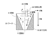
図1Aは、ワーク10を、主軸12を回転軸として回転させ、その表面を切削工具14で切削加工する様子を示す説明図である。同図に示すように、主軸12と同方向の軸がZ軸であり、主軸12の直交する軸の一つがX軸である。切削工具14は、ワーク10の表面を所定のプログラムに基づき切削していくが、その加工は、例えばZ軸、またはZ軸と所定角度の加工方向Bに沿って進んでいく。このように加工が進んでいく方向を加工方向Bと呼ぶ。
<Explanation of the principle of rocking motion>
1A and 1B are explanatory diagrams for explaining the swinging operation.
FIG. 1A is an explanatory diagram illustrating a state in which the workpiece 10 is rotated about the main shaft 12 as a rotation axis, and the surface of the workpiece 10 is cut by the cutting tool 14. As shown in the figure, the axis in the same direction as the main axis 12 is the Z axis, and one of the axes orthogonal to the main axis 12 is the X axis. The cutting tool 14 cuts the surface of the workpiece 10 based on a predetermined program, and the processing proceeds along, for example, the Z axis or a processing direction B having a predetermined angle with the Z axis. The direction in which the processing proceeds in this way is called a processing direction B.
このような切削加工を行う際に、切削工具14は、加工方向Bに揺動Aされている。この揺動Aによって、例えば切屑を細かく分断することができるようになるとされている。この揺動Aによって、切削工具14は加工方向にいわば振動していることになる。切削工具14がワーク10に対して接触/非接触を繰り返すことになる。切削工具14がワーク10に対して接触する場合は、切削工具14は、ワーク10の表面上で、図1Aにおける切削Dの軌跡を描いて移動する。他方、切削工具14がワーク10に対して接触していない場合は、切削工具14は、ワーク10の表面上で、図1Aにおける空振りCの軌跡を描いて移動する。
このように断続的な切削が行われることによって、切屑を細かく分断することや、切削工具14の効果的な冷却が可能となる。
When performing such cutting, the cutting tool 14 is swung A in the processing direction B. It is said that, for example, the chips can be finely divided by the swing A. By this swing A, the cutting tool 14 vibrates in the processing direction. The cutting tool 14 repeats contact / non-contact with the workpiece 10. When the cutting tool 14 comes into contact with the workpiece 10, the cutting tool 14 moves on the surface of the workpiece 10 while drawing the locus of the cutting D in FIG. 1A. On the other hand, when the cutting tool 14 is not in contact with the workpiece 10, the cutting tool 14 moves on the surface of the workpiece 10 while drawing a locus of the idle swing C in FIG. 1A.
By performing intermittent cutting in this way, it is possible to finely cut off chips and to effectively cool the cutting tool 14.
図1Bは、切削工具が揺動される他の例を示す説明図である。同図は、内部に空洞があるワーク20の空洞内部を切削工具24で切削加工する様子を示す説明図である。図1Bにおいてはワーク20に対して切削工具24が回転しており、その軸が主軸となる。
すなわち、本特許において、主軸は2通りの場合がある。図1Aにおいては、主軸12とは、ワーク10の回転する軸である。図1Bにおいては、主軸22とは、切削工具24の回転する軸をいう。
なお、図1Bにおいても、図1Aと同様に、主軸22と同方向の軸がZ軸であり、主軸22の直交する軸の一つがX軸である。切削工具24は、ワーク10の空洞内部の表面を所定のプログラムに基づき切削していくが、その加工は、図1Aと同様、加工方向Bに沿って進んでいく。
FIG. 1B is an explanatory diagram illustrating another example in which the cutting tool is swung. This figure is an explanatory view showing a state in which the inside of the cavity of the workpiece 20 having a cavity inside is cut by the cutting tool 24. In FIG. 1B, the cutting tool 24 is rotating with respect to the workpiece 20, and its axis becomes the main axis.
In other words, in this patent, there are two main spindles. In FIG. 1A, the main shaft 12 is a shaft on which the workpiece 10 rotates. In FIG. 1B, the main shaft 22 refers to the axis on which the cutting tool 24 rotates.
In FIG. 1B, as in FIG. 1A, the axis in the same direction as the main shaft 22 is the Z axis, and one of the axes orthogonal to the main shaft 22 is the X axis. The cutting tool 24 cuts the surface inside the cavity of the workpiece 10 based on a predetermined program, and the machining proceeds along the machining direction B as in FIG. 1A.
図1Bにおいても、切削工具24は、加工方向Bに揺動Aされ、切削工具24はワーク20に対して接触/非接触を繰り返す。切削工具24がワーク20に対して接触する場合は、切削工具24は、ワーク20の表面上で、図1Bにおける切削Dの軌跡を描いて移動する。他方、切削工具24がワーク20に対して接触していない場合は、切削工具24は、ワーク20の表面上で、図1Bにおける空振りCの軌跡を描いて移動する。
図1A及び図1Bにおいては、いずれも切削工具14、24側が揺動される例を説明したが、ワーク10、20側が揺動されるように構成されていてもよい。
Also in FIG. 1B, the cutting tool 24 is swung A in the processing direction B, and the cutting tool 24 repeats contact / non-contact with the workpiece 20. When the cutting tool 24 comes into contact with the workpiece 20, the cutting tool 24 moves on the surface of the workpiece 20 while drawing a locus of the cutting D in FIG. 1B. On the other hand, when the cutting tool 24 is not in contact with the workpiece 20, the cutting tool 24 moves on the surface of the workpiece 20 while drawing a locus of the idle swing C in FIG. 1B.
In FIGS. 1A and 1B, the example in which the cutting tools 14 and 24 side are swung has been described. However, the workpieces 10 and 20 side may be swung.
従来の技術においては、切削工具14(24)等を駆動するサーボモータに、当該揺動の指令を本来の指令に加えて与えることにより揺動が実現されている。例えば、従来は、その時点における指令(指令、主軸の回転速度)のみを考慮して揺動指示を行っているので、その経路の近傍に、切削工具と干渉する干渉体が位置する場合は、その干渉体と切削工具とが干渉してしまうことが考えられる。
本実施形態においては、この揺動動作を、加工動作の初期(動作開始期間Sと呼ぶ)や終期(動作終了期間Tと呼ぶ)において調整し、加工経路の近傍に位置する干渉体との干渉を抑制することができるサーボ制御装置を提案する。この揺動動作の調整は、揺動の振幅にオフセット値を加えることによって、実現されている。
In the prior art, the swing is realized by giving the swing command in addition to the original command to the servo motor that drives the cutting tool 14 (24) and the like. For example, conventionally, since the swing instruction is performed considering only the command at that time (command, rotation speed of the spindle), when an interference body that interferes with the cutting tool is located near the path, It is conceivable that the interference body and the cutting tool interfere with each other.
In the present embodiment, this swinging operation is adjusted at the initial stage (referred to as an operation start period S) or the final stage (referred to as an operation end period T) of the machining operation, and interference with an interference body located near the machining path. A servo control device capable of suppressing the above is proposed. The adjustment of the swing operation is realized by adding an offset value to the swing amplitude.
特に、本実施形態におけるサーボ制御装置においては、指令加速度に応じたオフセット値を揺動指令に加算することを特徴とする。すなわち、加速度が正方向(加工方向)に大きい場合は、動作開始期間S(動作の初期の期間)であると判断し、揺動の振幅に加工方向のオフセット値を加える。このオフセット値を前進オフセットと呼ぶ。また、加速度が負方向(加工方向の反対方向)に大きい場合は、動作終了期間T(動作の終期の期間)であると判断し、揺動の振幅に加工方向と逆方向のオフセット値を加える。このオフセット値を後退オフセットと呼ぶ。
なお、本実施形態においては、動作開始期間と、動作終了期間との双方で揺動の振幅をオフセットする例を説明するが、いずれか一方の期間のみオフセットさせてもよい。
なお、本特許で経路とは加工経路を意味し、具体的には、例えば切削工具に対する位置指令によって切削工具が移動する(辿る)経路である。加工経路は、指令経路とも言う。
In particular, the servo control device according to the present embodiment is characterized in that an offset value corresponding to the commanded acceleration is added to the swing command. That is, when the acceleration is large in the positive direction (machining direction), it is determined that it is the operation start period S (the initial period of the operation), and an offset value in the machining direction is added to the swing amplitude. This offset value is called a forward offset. If the acceleration is large in the negative direction (opposite to the machining direction), it is determined that it is the operation end period T (the end period of the operation), and an offset value opposite to the machining direction is added to the swing amplitude. . This offset value is called a reverse offset.
In this embodiment, an example in which the amplitude of oscillation is offset in both the operation start period and the operation end period will be described. However, only one of the periods may be offset.
In this patent, the path means a machining path, and specifically, a path along which the cutting tool moves (follows) by a position command for the cutting tool, for example. The machining path is also called a command path.
このように、本実施形態においては、オフセット値を指令加速度に基づき算出し、算出したオフセット値を揺動指令(の振幅)に加算しているが、オフセット値は、上位の制御装置(上位制御装置と呼ぶ)から提供されてもよい。上位制御装置は、切削工具の加工動作に対する位置指令を出力するので、動作開始期間S、動作終了期間Tを認識することができると考えられる。そのため、この上位制御装置が、揺動指令の振幅に加えるべきオフセット値を提供することも好ましいと考えられる。
揺動指令は、基本的に、揺動の周波数(揺動周波数と呼ぶ)と、揺動の振幅(揺動振幅と呼ぶ)とを含むが、その他に種々のパラメータを含んでいてもよい。例えば、揺動指令は、切削工具の送り量、前進量、後退量、前進速度、後退速度等を含んでいてもよい。
As described above, in the present embodiment, the offset value is calculated based on the command acceleration, and the calculated offset value is added to the swing command (the amplitude thereof). (Referred to as a device). Since the host controller outputs a position command for the machining operation of the cutting tool, it is considered that the operation start period S and the operation end period T can be recognized. For this reason, it is considered preferable that the host controller provides an offset value to be added to the amplitude of the swing command.
The swing command basically includes a swing frequency (referred to as swing frequency) and a swing amplitude (referred to as swing amplitude), but may include various other parameters. For example, the swing command may include a cutting tool feed amount, a forward amount, a reverse amount, a forward speed, a reverse speed, and the like.
<構成>
以下、本実施形態に係るサーボ制御装置100の構成を図に基づき説明する。本実施形態に係るサーボ制御装置100の構成ブロック図が図2に示されている。図2に示すように、上位制御装置200は、位置指令を出力する。サーボ制御装置100は、工作機械(不図示)のサーボモータ400を駆動して、この位置指令に合うように工作機械の切削工具やワークを制御する。サーボ制御装置100は、請求の範囲の制御装置の好適な一例に相当する。
上位制御装置200は、サーボ制御装置100を介して工作機械を制御する上位の制御装置であり、例えば、コンピュータで構成することができる。また例えば、ユーザが操作を行う制御コンソール・制御パネルのような構成でもよい。また、複数の工作機械を統合管理する管理装置(管理コンピュータ)のような構成でもよい。また、工場全体を制御する制御装置(制御コンピュータ)のような構成を上位制御装置200として利用してもよい。
<Configuration>
Hereinafter, the configuration of the
The
サーボ制御装置100は、CPUやメモリを備えたコンピュータで構成することが好ましく、以下説明する各部(各計算部、制御部等)は、当該CPUがメモリ中の所定のプログラムを実行することによって実現することができる。この所定のプログラムは、請求の範囲のコンピュータプログラムの好適な一例に相当する。
本実施形態に係るサーボ制御装置100は、揺動指令計算部102と、加速度計算部104と、オフセット値計算部106と、揺動指令補正部108と、位置・速度・電流制御部116と、を備えている。
The
The
揺動指令計算部102は、主軸の回転速度と、上位制御装置200が出力する位置指令とに基づき、揺動指令を計算する。加速度計算部104は、サーボモータ400の加速度を計算する。加速度の計算は、位置指令に基づく手法と、位置フィードバック値に基づく手法の2種類があるが、その詳細は後述する。オフセット値計算部106は、加速度計算部104が計算した加速度に基づき、オフセット値を計算する。揺動指令補正部108は、揺動指令にオフセット値を加えて、揺動指令を補正する。オフセット値は、オフセット値計算部106が計算したオフセット値を利用する手法と、上位制御装置200が提供するオフセット値を利用する手法があるが、その詳細は後述する。位置・速度・電流制御部116は、位置指令に補正した揺動指令を加えて、サーボモータに対する駆動信号を求める。
The swing
さらに、サーボ制御装置100は、主軸の回転速度を取得する回転速度取得部118と、上位制御装置200からの位置指令を取得する位置指令取得部120と、位置フィードバック値を取得する位置取得部122と、を備えている。なお、主軸の回転速度は、分(秒)当たりの回転数でもいいし、角速度でもよい。これら各取得部は、コンピュータの入力インターフェースと、その入力インターフェースを制御して情報を取得するプログラムと、そのプログラムを実行するCPUと、とから構成することが好ましい。なお、このプログラムも、請求の範囲のコンピュータプログラムの好適な一例に相当する。また、各取得部は、外部からのデータを保存するバッファ等を含んでいてもよい。
Further, the
<動作>
以下、サーボ制御装置100の具体的な動作を、図2の構成ブロック図、及び、図3、図4、図5A、図5Bの動作を説明するグラフや説明図、図6のフローチャートに基づき説明する。
位置指令取得部120は、上位制御装置200が出力する、切削工具を駆動するサーボモータ400に対する位置指令、または、ワーク10(20)を駆動するサーボモータ400に対する位置指令、を取得するインターフェースである。位置指令取得部120が取得した位置指令は、揺動指令計算部102と、加速度計算部104と、加算器110と、に供給される。
位置指令取得部120は、請求の範囲の位置指令取得部の好適な一例に相当する。また、位置指令取得部120による位置指令の取得動作は、図6の工程S1:位置指令取得工程に該当する。
<Operation>
Hereinafter, the specific operation of the
The position
The position
回転速度取得部118は、回転するワークまたは切削工具の主軸の回転速度を取得するインターフェースであり、ここで取得した回転速度は、揺動指令計算部102に供給される。
回転速度取得部118は、請求の範囲の回転速度取得部の好適な一例に相当する。回転速度取得部118による主軸の回転速度の取得動作は、図6のフローチャートにおける工程S2:回転速度取得工程に該当する。
なお、本実施形態における回転速度は、切削工具の回転速度である場合でもよいし、ワークの回転速度である場合でもよい。また、回転速度は、切削工具等の主軸に回転速度センサを設けて取得してもよいが、上位制御装置200が出力する位置指令に基づき、その時間変化率から回転速度を求めてもよい。また、後述するサーボモータ400の回転角度を検出する検出器500が検出する位置フィードバック値の変化率(または微分)から算出することも好適である。
The rotation
The rotation
The rotational speed in the present embodiment may be the rotational speed of the cutting tool or the rotational speed of the workpiece. The rotational speed may be obtained by providing a rotational speed sensor on a main shaft of a cutting tool or the like, but based on the position command output from the
加速度計算部104は、位置指令に基づき、サーボモータ400の加速度を計算する。サーボモータ400の位置を微分すれば、速度が得られる。そして、速度を微分すれば、加速度が得られる。なお、得られた加速度を指令加速度と呼ぶ場合もある。
加速度計算部104のこのような動作も、サーボ制御装置100のCPUが、加速度計算部104のこのような動作を記述するプログラムを実行することによって実現している。このプログラムは、サーボ制御装置100内の所定の記憶装置に格納されているが、外部の記憶装置に格納されていてもよい。また、このプログラムも、請求の範囲のコンピュータプログラムの好適な一例に相当する。
本実施形態において特徴的なことの一つは、このように、加速度を計算することで、サーボモータ400が実行する動作が、動作開始期間Sなのか、動作終了期間Tなのか、それ以外の期間における動作なのかを判断していることである。この判断に基づいて、工具の揺動指令(の振幅)をオフセットすることができる。
The
Such an operation of the
One of the characteristic features of the present embodiment is that the operation executed by the
なお、加速度計算部104は、位置指令ではなく、サーボモータ400の実際の動きから、実際の加速度を計算することも好ましい。このようにして加速度を計算すれば、実際の動きに基づくより正確な加速度の値を計算することができると考えられる。サーボモータの400の位置は、図2に示す検出器500によって検出され、位置フィードバック値として出力される。位置フィードバック値は、位置取得部122を通じてサーボ制御装置100に取り込まれる。位置取得部122は、取得した位置フィードバック値を、加速度計算部104と、加算器110とに送出する。
It is preferable that the
加速度計算部104は、位置指令の代わりに、この位置フィードバック値を用いて、サーボモータ400の実際の位置を検出し、それを微分することによって、速度を算出し、さらに微分することによって加速度を計算することができる。実際のサーボモータ400の動きに基づいて加速度を検出することができるので、上位制御装置200から提供された位置指令に基づいて計算することに比べて、より正確な加速度を求めることができると考えられる。ただし、実際のサーボモータ400の動きをフィードバックした値を用いているので、上位制御装置200からの位置指令を利用する場合と比べて、加速度の計算が多少遅れてしまうことも考えられる。
なお、加速度計算部104は、請求の範囲の加速度計算部の好適な一例に相当する。また、これまで述べた加速度計算部104の加速度を算出する動作は、図6の工程S3:加速度計算工程に該当する。
The
The
次に、揺動指令計算部102は、取得した位置指令と、取得した回転速度と、に基づいて揺動指令を計算する。本実施形態においては、具体的には、揺動指令計算部102は、上位制御装置200が出力する位置指令に基づき、次のような手順で揺動指令を計算する。これらの計算も、サーボ制御装置100のCPUが、揺動指令計算部102の機能を記述するプログラムを実行することによって実現している。また、このプログラムも、請求の範囲のコンピュータプログラムの好適な一例に相当する。
Next, the swing
まず、揺動指令計算部102は、取得した位置指令と、取得した回転速度と、に基づいて揺動振幅を計算する。例えば、位置指令と主軸の回転速度とに基づき、主軸の1回転当たりの送り量を求め、その1回転当たりの送り量の例えば1.5倍を揺動振幅として設定してよい。この1.5とは、請求の範囲の第1の定数の好適な一例に相当する。
揺動振幅の計算を行う揺動指令計算部102は、請求の範囲の揺動振幅計算部の好適な一例に相当する。また、この揺動指令計算部102の揺動振幅の計算動作は、図6の工程S4:揺動指令計算工程の一部に該当する。
First, the
The
次に、揺動指令計算部102は、取得した回転速度に基づいて揺動周波数を計算する。例えば、回転周波数の1.5倍の値を揺動周波数として設定することが好適である。この1.5とは、請求の範囲の第2の定数の好適な一例に相当する。
揺動周波数の計算を行う揺動指令計算部102は、請求の範囲の揺動周波数計算部の好適な一例に相当する。また、揺動指令計算部102の揺動周波数の計算動作は、図6の工程S4:揺動指令計算工程の一部に該当する。
Next, the swing
The swing
次に、揺動指令計算部102は、計算した揺動振幅と、計算した揺動周波数と、からなる揺動指令を計算する。この揺動指令は、上位制御装置200から出力される位置指令とともにサーボモータに送られることによって、切削工具(またはワーク)の移動に際して、揺動動作が加えられる。
この揺動指令の計算を行う揺動指令計算部102は、請求の範囲の揺動指令計算部102の好適な一例に相当する。また、揺動指令計算部102の揺動指令の計算動作は、図6の工程S4:揺動指令計算工程の一部に該当する。
Next, the swing
The swing
次に、オフセット値計算部106は、加速度計算部104が計算した加速度に基づき、揺動指令に加えるべきオフセット値を計算する。このような動作も、サーボ制御装置100のCPUが、オフセット値計算部106のこのような動作を記述するプログラムを実行することによって実現している。このプログラムは、サーボ制御装置100内の所定の記憶装置に格納されているが、外部の記憶装置に格納されていてもよい。また、このプログラムも、請求の範囲のコンピュータプログラムの好適な一例に相当する。
Next, the offset
<動作開始期間S、動作終了期間T>
オフセット値計算部106は、計算された加速度が正の値であった場合、サーボモータ400は、動作開始期間Sにおける動作を実行していると判断する。そして、動作開始期間Sと判断した場合は、加工経路方向のオフセット値を算出する。
図3には、サーボモータ400の送り量、すなわち位置と、時間との関係を示すグラフが示されている。ここで例として説明する加工動作においては、サーボモータ400は、位置P2から移動を開始し、位置P1で停止し、加工動作を終了するものとする。この図3の例においては、移動開始してから加速度が正の値である期間が動作開始期間Sと判断する。つまり、サーボモータ400が加速している期間を表す。逆に言えば、サーボモータ400が加速している期間は、加工動作が開始してから初期の期間、すなわち動作開始期間Sと判断している。
<Operation start period S, operation end period T>
When the calculated acceleration is a positive value, the offset
FIG. 3 shows a graph showing the relationship between the feed amount of the
本実施形態において特徴的なことは、オフセット値計算部106が、加速度に基づき、動作開始期間Sであると判断した場合は、加工経路方向のオフセット値を算出する(計算する)ことである。加工経路方向、すなわち移動していく方向のオフセット値を算出することによって、揺動の振幅を加工経路方向にオフセットさせることができ、切削工具が開始位置であるP2より常にP1側に移動するように制御することができる。この結果、切削工具が位置P2から、移動先であるP1と反対側に干渉体Qが位置している場合でも、切削工具が、揺動動作によって、干渉体Q側に移動してしまうことを抑制することができる。図3にはこの揺動の様子が示されている。図3に示すように、工具の指令経路に対して所定の振幅、所定の周波数で揺動動作が重畳しているが、この振幅を位置P1側にオフセットさせることによって、切削工具がP2から見て、P1の反対側方向に移動しないように制御している。これによって、位置P2近傍(のP1とは反対側)に干渉体Qが位置する場合、この干渉体Qへの干渉を抑制することができる。
次に、オフセット値計算部106は、加速度がほぼ0である場合は、動作開始期間Sでも、動作終了期間Tでもないと判断し、オフセット値として0を算出(計算)する。
What is characteristic in the present embodiment is that the offset
Next, when the acceleration is approximately zero, the offset
他方、オフセット値計算部106は、計算された加速度が負の値であった場合、サーボモータ400は、動作終了期間Tであると判断する。そして、動作終了期間Tである場合は、加工経路方向の逆方向のオフセット値を算出する。
図3に示す例では、サーボモータ400は、位置P2から移動を開始し、位置P1で停止し、加工動作を終了する。この図3の例においては、位置P2が近づき、加速度が負の値である期間が、動作終了期間Tである。つまり、サーボモータ400が減速している期間を表す。逆に言えば、サーボモータ400が減速している期間を、加工動作が終了する直前の期間、すなわち動作終了期間Tと判断している。
On the other hand, when the calculated acceleration is a negative value, the offset
In the example shown in FIG. 3, the
本実施形態において特徴的なことは、オフセット値計算部106が、加速度に基づき、動作終了期間Tであると判断した場合は、加工経路方向とは逆方向のオフセット値を算出する(計算する)ことである。加工経路方向と逆方向、すなわち終了点P1から、開始点P2側に移動していく方向のオフセット値を算出することによって、揺動の振幅を開始点P1側、すなわち加工経路方向と逆方向にオフセットさせることができ、切削工具が終了点P1より常に開始点P2側に移動するように制御することができる。この結果、位置P1から、開始点であるP2と反対側に干渉体Qが位置している場合でも、切削工具が、揺動動作によって、その干渉体Q側に移動してしまうことを抑制することができる。図3にはこの揺動の様子が示されている。図3に示すように、工具の指令経路に対して所定の振幅、所定の周波数で揺動動作が重畳しているが、この振幅を位置P2側にオフセットさせることによって、切削工具がP1から見て、P2の反対側方向に移動しないように制御している。これによって、位置P1近傍(のP2とは反対側)に干渉体Qが位置する場合、この干渉体Qへの干渉を抑制することができる。
What is characteristic in the present embodiment is that the offset
このようにして、切削工具が揺動動作によって、加工経路の外部にはみ出してしまうことを抑制しているので、加工経路の近傍に何らかの干渉体Qが位置する場合でも、その干渉体Qとの干渉を抑制することができる(図3参照)。
なお、オフセット値計算部106は、請求の範囲のオフセット値計算部の好適な一例に相当する。また、これまで述べたオフセット値計算部106のオフセット値を算出する(計算する)動作は、図6の工程S5:オフセット値計算工程に該当する。
In this way, since the cutting tool is prevented from protruding outside the machining path due to the swinging motion, even when any interference body Q is located in the vicinity of the machining path, Interference can be suppressed (see FIG. 3).
The offset
揺動指令補正部108は、オフセット値計算部106が計算したオフセット値に基づき、揺動指令計算部102が計算した揺動指令を補正する。具体的には、図3で説明したように、揺動指令補正部108は、オフセット値計算部106が計算したオフセット値を、揺動指令中の振幅に加算するのである。揺動指令補正部108は、このようにして補正した揺動指令を、加算器110に供給する。
このような動作も、サーボ制御装置100のCPUが、揺動指令補正部108のこのような動作を記述するプログラムを実行することによって実現している。すなわち、揺動指令補正部103は、揺動指令を補正する動作を記述するプログラムと、このプログラムを実行するサーボ制御装置100のCPUと、から実現されている。
上記プログラムは、サーボ制御装置100内の所定の記憶装置に格納されているが、外部の記憶装置に格納されていてもよい。また、このプログラムも、請求の範囲のコンピュータプログラムの好適な一例に相当する。
The swing command correcting unit 108 corrects the swing command calculated by the swing
Such an operation is also realized by the CPU of the
The program is stored in a predetermined storage device in the
揺動指令補正部108は、このように、オフセット値計算部106が計算したオフセット値を利用するが、他の手法で取得したオフセット値を利用してもよい。例えば、上位制御装置200が提供するオフセット値を利用して揺動指令を補正することも好適である。
本実施形態におけるオフセット値は、サーボモータ400が動作開始期間Sに位置するか、動作終了期間Tに位置するか、それ以外の期間に位置するかに応じて決定される。この期間の判断は、オフセット値計算部106が加速度に基づき判断することが好適であるが、元々の位置指令を発した上位制御装置200が本来判断することができるので、上位制御装置200がその判断に基づきオフセット値を出力することも好ましい。
そこで、上位制御装置200がオフセット値を出力する場合は、揺動指令補正部108が上位制御装置200が出力するオフセット値を利用して、これを揺動指令(の振幅)に加算して、揺動指令の補正をすることもできる。サーボ制御装置100は、上位制御装置200が出力するオフセット値を、オフセット値取得部124を介して取得してよい。オフセット値取得部124は取得したオフセット値を、揺動指令補正部108に供給する。揺動指令補正部108は、このようにして上位制御装置200から取得したオフセット値を利用して補正した揺動指令を、加算器110に供給する。
The swing command correction unit 108 uses the offset value calculated by the offset
The offset value in this embodiment is determined according to whether the
Therefore, when the
なお、揺動指令補正部108は、請求の範囲のオフセット部の好適な一例に相当する。
また、以上述べたような揺動指令補正部108の動作は、図6の工程S6:オフセット工程に該当する。
The swing command correction unit 108 corresponds to a preferred example of the offset unit in the claims.
The operation of the swing command correction unit 108 as described above corresponds to step S6: offset step in FIG.
<サーボモータ400の速度と、加速度と、オフセットの関係>
本実施形態においては、サーボモータの動作開始期間S、動作終了期間T、においてオフセット値を計算し、それ以外の期間では、特段オフセット値は計算していない。換言すれば、上記動作開始期間S、動作終了期間T以外の期間では、オフセット値を「0」としている。
このような、各期間と、速度と、加速度と、オフセット値との間系を示すグラフの例が図4に示されている。図4の(a)のグラフは、横軸に時間をとり、縦軸にサーボモータ400の速度をとったグラフである。図4の(b)のグラフは、横軸に時間をとり、縦軸にサーボモータ400の加速度をとったグラフである。図4の(c)のグラフは、横軸に時間をとり、縦軸にオフセット値をとったグラフである。
図4のグラフに示すように、サーボモータ400は、動作開始期間Sにおいて、一定の加速度(図4の(b)のグラフ参照)で加速していき、速度が増加していく(図4の(a)のグラフ参照)。その正の加速度が生じている期間を、動作開始期間Sと判断して、オフセットを計算している(図4の(c)のグラフ参照)。動作開始期間Sにおけるこのオフセット値は、正の所定の値であり、加工方向に対して前進方向のオフセットである。したがって、特にこのオフセット値を、前進オフセットと称する(図4の(c)参照))。
<Relationship between
In this embodiment, the offset value is calculated in the operation start period S and the operation end period T of the servo motor, and no special offset value is calculated in other periods. In other words, in a period other than the operation start period S and the operation end period T, the offset value is “0”.
FIG. 4 shows an example of a graph showing such a system between each period, speed, acceleration, and offset value. 4A is a graph in which time is plotted on the horizontal axis and the speed of the
As shown in the graph of FIG. 4, the
このように、動作開始期間Sにおいては、加工方向に対して前進方向にオフセットさせているので、揺動があっても、加工経路から切削工具がはみ出てしまう(図3のP2を越えてはみ出してしまう)ことを抑制することができる。その結果、加工経路の近傍に所定の干渉体Qが位置している場合でも、干渉体Qとの干渉を抑制することができる。
また、図4のグラフに示すように、サーボモータ400は、動作終了期間Tにおいて、一定の負の加速度(図4の(b)のグラフ参照)で減速していき、速度が減少していく(図4の(a)のグラフ参照)。その負の加速度が生じている期間を、動作終了期間Tと判断して、オフセットを計算している(図4の(c)のグラフ参照)。動作終了期間Tにおけるこのオフセット値は、負の所定の値であり、加工方向に対して後退方向のオフセットである。したがって、特にこのオフセット値を、後退オフセットと称する(図4の(c)参照))
As described above, in the operation start period S, the cutting tool is protruded from the machining path even if it is swung because it is offset in the forward direction with respect to the machining direction. Can be suppressed. As a result, even when the predetermined interference body Q is located in the vicinity of the machining path, interference with the interference body Q can be suppressed.
Further, as shown in the graph of FIG. 4, the
このように、動作終了期間Tにおいては、加工方向に対して後退方向にオフセットさせているので、揺動があっても、加工経路から切削工具がはみ出てしまう(図3のP1を越えてはみ出してしまう)ことを抑制することができる。その結果、加工経路の近傍に所定の干渉体Qが位置している場合でも、干渉体Qとの干渉を抑制することができる。求めているオフセット値は、「動作開始期間S及び動作終了期間T」以外では、「0」としている(つまり、オフセットさせない)。
本実施形態においては、このように、揺動指令の振幅をオフセットさせることを特徴とするが、そのオフセットの処理は、例えば、動作開始期間Sだけ実行してもよい。また、逆に、動作終了期間Tだけ実行してもよい。また、図3、図4等で説明したように、動作開始期間S、動作終了期間Tの双方でオフセットを実行することも好適である。
As described above, in the operation end period T, since the offset is made in the backward direction with respect to the processing direction, the cutting tool protrudes from the processing path even if there is rocking (exceeding P1 in FIG. 3). Can be suppressed. As a result, even when the predetermined interference body Q is located in the vicinity of the machining path, interference with the interference body Q can be suppressed. The obtained offset value is “0” except for “the operation start period S and the operation end period T” (that is, no offset is performed).
In this embodiment, the amplitude of the swing command is offset as described above. However, the offset processing may be executed only during the operation start period S, for example. Conversely, it may be executed only during the operation end period T. In addition, as described with reference to FIGS. 3 and 4 and the like, it is also preferable to perform the offset in both the operation start period S and the operation end period T.
<干渉体Qと、ワーク10との関係>
加工対象であるワーク10(20)に対して、干渉体Qは指令経路(加工経路)の中には位置してはならないが、指令経路の近傍に位置してしまうことがある。干渉体Qはどのようなものでもよいが、例えば、ネジのネジ山部分を加工しようとする場合のそのネジ頭の部分等が、干渉体Qとなり得る。また、円筒形のワーク10(20)を支える治具部分が、干渉体Qとなる場合もある。
<Relationship between interference body Q and workpiece 10>
For the workpiece 10 (20) to be machined, the interference body Q must not be positioned in the command path (machining path), but may be positioned in the vicinity of the command path. The interference body Q may be any type, but for example, a screw head portion or the like when a thread portion of a screw is to be processed can be the interference body Q. In addition, the jig portion that supports the cylindrical workpiece 10 (20) may be the interference body Q.
図5A、図5Bには、干渉体Qとワーク10(20)との位置関係の一例を説明する説明図が示されている。 5A and 5B are explanatory diagrams illustrating an example of the positional relationship between the interference body Q and the workpiece 10 (20).
図5Aには、ワーク10(20)の加工動作を開始した際の動作開始期間Sにおける、ワーク10(20)の加工状態の断面図が示されている。この図5Aに示すX軸、Z軸は、図1Aと同様の座標であり、Z軸方向に加工方向Bが取られている。図5Aにおいては、ワーク断面の輪郭Eが示されており、ワーク10(20)に対して切削工具が、指令経路Fに沿って動く。実際には、切削工具には揺動指令が重畳して加えられているので、工具経路H(=指令経路+揺動指令)は、図5Aに示すようにカーブを描いたものとなる。このような加工動作が行われている場合、ワーク10(20)の端部に治具等の干渉体Qが取り付けられているときは、揺動動作によって切削工具の工具経路Hが、指令経路Fから揺動指令の分だけずれることによって、干渉体Qとの間で干渉Iが生じる可能性がある(図5A参照)。このような干渉Iを抑制するために、本実施形態では、揺動指令(の振幅)にオフセットを加えたものである。 FIG. 5A shows a cross-sectional view of the machining state of the workpiece 10 (20) in the operation start period S when the machining operation of the workpiece 10 (20) is started. The X-axis and Z-axis shown in FIG. 5A are the same coordinates as in FIG. 1A, and the machining direction B is taken in the Z-axis direction. In FIG. 5A, an outline E of the workpiece cross section is shown, and the cutting tool moves along the command path F with respect to the workpiece 10 (20). Actually, since a swing command is superimposed on the cutting tool, the tool path H (= command path + swing command) is a curve drawn as shown in FIG. 5A. When such a machining operation is performed, when the interference body Q such as a jig is attached to the end of the workpiece 10 (20), the tool path H of the cutting tool is changed to the command path by the swinging operation. By deviating from F by the amount of the swing command, interference I may occur with the interfering body Q (see FIG. 5A). In order to suppress such interference I, in this embodiment, an offset is added to the swing command (its amplitude).
同様に、図5Bには、ワーク10(20)の加工動作の終了する際の動作終了期間Tにおける、ワーク10(20)の加工状態の断面図が示されている。この図5Bに示すX軸、Z軸も、図1Aと同様の座標であり、Z軸方向に加工方向Bが取られている。図5Bにおいては、ワーク断面の輪郭Eが示されており、ワーク10(20)に対して切削工具が、曲線の工具経路H(=指令経路+揺動指令)にしたがって動く。このような加工動作が行われている場合、ワーク10(20)の端部にワーク10(20)を把持するための把持チャック等の干渉体Qが取り付けられているときは、揺動動作によって、切削工具と干渉体Qとの間で干渉Iが生じる可能性がある(図5B参照)。このような干渉Iを抑制するために、本実施形態では、揺動指令(の振幅)にオフセットを加え、切削工具が干渉体Qに移動してしまうことを抑制したものである。 Similarly, FIG. 5B shows a cross-sectional view of the machining state of the workpiece 10 (20) during the operation end period T when the machining operation of the workpiece 10 (20) is completed. The X axis and the Z axis shown in FIG. 5B are also the same coordinates as in FIG. 1A, and the machining direction B is taken in the Z axis direction. In FIG. 5B, an outline E of the workpiece cross section is shown, and the cutting tool moves with respect to the workpiece 10 (20) according to a curved tool path H (= command path + oscillation command). When such a machining operation is performed, when an interference body Q such as a grip chuck for gripping the workpiece 10 (20) is attached to the end of the workpiece 10 (20), Interference I may occur between the cutting tool and the interference body Q (see FIG. 5B). In order to suppress such interference I, in the present embodiment, an offset is added to the swing command (its amplitude) to prevent the cutting tool from moving to the interference body Q.
このようにして補正された揺動指令は、加算器110において、位置指令に加えられてから、位置・速度・電流制御部116に供給される。なお、加算器110は、上位制御装置200から出力された位置指令と、補正された揺動指令と、位置フィードバック値と、を加算し、位置・速度・電流制御部116に供給する。
なお、図2において、加算器110は、補正した揺動指令側をマイナス「−」記号で表しているが、本実施形態において、揺動指令の極性が位置指令と反対方向だからであり、極性に応じて、「−」または「+」にすればよい。また、位置フォードバック値は、サーボモータ400の実際の位置のフィードバックであり、サーボモータ400の位置をフィードバックすることによってフィードバック制御を行い、より正確な位置に制御しようとしたものである。
The swing command corrected in this way is added to the position command in the
In FIG. 2, the
位置・速度・電流制御部116は、補正後の揺動指令が加算された位置指令に基づき、サーボモータ400を駆動する駆動信号を求めて、外部のアンプ300にこの駆動信号を供給(出力)する。
したがって、位置・速度・電流制御部116と加算器110とは、請求の範囲の駆動部の好適な一例に相当する。また、位置・速度・電流制御部116と加算器110とによる、駆動信号の出力は、図6のフローチャートの工程S7:駆動工程に該当する。
The position / speed /
Therefore, the position / velocity /
アンプ300は、上述した駆動信号を増幅し、サーボモータ400を駆動するのに十分な電力をサーボモータ400に供給する。サーボモータ400は、(増幅された)駆動信号で駆動される。なお、図2においては、アンプ300やサーボモータ400が、それぞれ1個ずつ示されているが、それぞれ複数個備えられていてよい。多軸制御の場合(複数の制御軸を備えている工作機械の場合)は、その軸数分だけアンプ300及びサーボモータ400が備えられていてよい。
The
サーボモータ400の駆動軸には検出器500が備えられており、サーボモータ400の位置を検出することによって、実質的には切削工具やワークの位置を検出することができる。検出器500は、ロータリーエンコーダや、リニアエンコーダ等を用いて構成することができる。この検出器500は、位置フィードバック値を、位置取得部122に対して出力する。位置取得部122は、サーボモータ400の位置(切削工具の位置またはワークの位置)を位置フィードバック値として取得するインターフェースである。位置取得部122が取得した位置フィードバック値は、加算器110に加えられる。これによって、いわゆるフィードバック制御が実行され、サーボモータ400の位置と、位置指令による位置とをより正確に合わせることができる。
A
なお、図6のフローチャートにおいては、工程S7:駆動工程の後、上位制御装置200から引き続き出力される位置指令の取得が実行され(工程S1:位置指令取得工程)、以下、工程S1からの処理が順次繰り返される。ただし、実際には、出力される位置指令に対して、図6のフローチャートに示される処理が連続して実行されるので、パイプライン的に、図6における各処理は並行して実行されてよい。
以上述べたようにして、本実施形態に係るサーボ制御装置100は、複数の制御軸を有する工作機械のサーボモータに対して揺動動作を実行させる。
特に、本実施形態においては、加工動作の初期(動作開始期間S)と終期(動作終了期間T)とにおいて、揺動指令の振幅にオフセットを加えている。このような動作によって、指令経路(加工経路)の近傍に位置する干渉体Qと切削工具等との干渉を抑制することができる。
In the flowchart of FIG. 6, acquisition of a position command continuously output from the
As described above, the
In particular, in the present embodiment, an offset is added to the amplitude of the swing command at the beginning (operation start period S) and the end (operation end period T) of the machining operation. By such an operation, interference between the interference body Q located near the command path (machining path) and the cutting tool or the like can be suppressed.
したがって、本実施形態においては、加工動作の初期(動作開始期間S)や終期(動作終了期間T)を効率的に求めることが必要となる。これに関して、本実施形態では、サーボモータ400の加速度を検出し、これに基づいて動作開始期間Sか、動作終了期間Tか、を判断しているので、効率的、かつ正確に各期間の判断をすることができる。
また、位置指令を出力する上位制御装置200は、本来、動作開始期間Sや動作終了期間Tを知ることができるので、上位制御装置200がこのような期間の判断に基づき、オフセット値を出力するように構成してもよい。この場合、本実施形態に係るサーボ制御装置100の揺動指令補正部108は、オフセット値計算部106が計算したオフセット値に代えて、上位制御装置200が出力するオフセット値を使用して、揺動指令にそのオフセット値を加算して補正した揺動指令を得てもよい。このような動作を採用する場合は、図2において、加速度計算部104及びオフセット値計算部106を備えていないサーボ制御装置100を構成して利用してもよい。
Therefore, in the present embodiment, it is necessary to efficiently obtain the initial stage (operation start period S) and the end stage (operation end period T) of the machining operation. In this regard, in the present embodiment, the acceleration of the
Further, since the
<第1の定数、第2の定数の設定>
第1の定数は、本実施形態では、1.5倍に設定したが、0.5倍から10倍の範囲で設定することができる。ここで、揺動振幅は、主軸が1回転する間の(ワーク10、または切削工具24)の移動量(加工方向への移動量)の0.5倍以上の振幅が通常は必要である。
また、主軸1回転の速度は、例えば、上述した主軸の角度の変化から推定(角速度)することもでき、移動速度は、位置指令の変化から推定(速度指令)することもできる。この推定した角速度から主軸1回転に要する時間が判明する。したがって、1回転の時間×速度指令を算出すれば、主軸1回転当たりのワーク10(または切削工具)の移動量を求めることができる。
<Setting of the first constant and the second constant>
The first constant is set to 1.5 times in the present embodiment, but can be set in a range of 0.5 to 10 times. Here, the swing amplitude normally needs to be 0.5 times or more the amount of movement (the amount of movement in the machining direction) of the workpiece 10 or the cutting tool 24 during one rotation of the main shaft.
The speed of one rotation of the main shaft can also be estimated (angular speed) from the change in the angle of the main shaft described above, and the moving speed can be estimated (speed command) from the change in position command. From this estimated angular velocity, the time required for one rotation of the main shaft is found. Therefore, if the time per rotation × speed command is calculated, the amount of movement of the workpiece 10 (or cutting tool) per one rotation of the main spindle can be obtained.
このようにして求めた移動量から、第1の定数倍して、揺動振幅を求める(設定する)ことができる。また、位置指令と、揺動振幅が加工方向への移動量の0.5倍以上となるように第1の所定の数を設定してもよい。このような第1の定数の算出は、人間が行ってもよいし、サーボ制御装置100や上位制御装置200が実行してもよい。
例えば、第1の定数は、1倍超〜2倍未満程度の範囲で設定することが好ましく、1.5倍近傍がより好ましい範囲である。これらの数値範囲も、請求の範囲の第1の定数の好適な例に相当する。また、例えば、第2の定数も、本実施形態では、1.5倍に設定したが、0.5倍から10倍の範囲で設定することができる。特に、1倍超〜2倍未満程度の範囲で設定することが好ましく、1.5倍近傍がより好ましい範囲である。これらの数値範囲も、請求の範囲の第2の定数の好適な例に相当する。
The oscillation amplitude can be obtained (set) by multiplying the obtained movement amount by a first constant. Further, the first predetermined number may be set so that the position command and the swing amplitude are 0.5 times or more of the movement amount in the machining direction. Such calculation of the first constant may be performed by a human or the
For example, the first constant is preferably set in a range of more than about 1 to less than about 2 times, and more preferably in the vicinity of 1.5 times. These numerical ranges also correspond to preferable examples of the first constant in the claims. Further, for example, the second constant is set to 1.5 times in the present embodiment, but can be set in a range of 0.5 times to 10 times. In particular, it is preferably set in the range of more than 1 time to less than 2 times, and the vicinity of 1.5 times is a more preferable range. These numerical ranges also correspond to suitable examples of the second constant in the claims.
また、これら第1の定数や、第2の定数は、上位制御装置200が、サーボ制御装置100に対して指示するように構成してもよい。この場合、サーボ制御装置100は、指示された第1の定数、第2の定数を、サーボ制御装置100内の所定のメモリに格納しておくことができる。また、第1の定数や、第2の定数は、ユーザが上位制御装置200を操作して設定してもよい。また、ユーザがサーボ制御装置100に対して直接これらの定数を設定してもよい。
Further, the first constant and the second constant may be configured so that the
<揺動指令の計算の制御>
なお、揺動指令計算部102は、種々の目的で様々な揺動指令を計算してよいが、例えば、切削の際に発生した切屑を細断する等の目的のためには、切削工具が進行する加工方向に、切削工具とワークとが相対的に揺動するような揺動指令を計算することが好適である。
<Control of calculation of swing command>
The swing
また、揺動指令計算部102は、外部からの指示によって、揺動指令の計算を開始、中断、または終了するように構成することも好適である。例えば、外部の上位制御装置200からの指示によって、揺動指令の計算を開始、中断、終了するように構成してもよい。
It is also preferable that the swing
上位制御装置200が出力したこのような指示を入力するためのインターフェース部がサーボ制御装置100に備えさせる必要があるが、他のインターフェース、例えば回転速度取得部118等と共用することも好適である。
It is necessary to provide the
また、揺動指令補正部108も、揺動指令計算部102と同様に、外部からの指示によって、揺動指令の補正を開始、中断、または終了するように構成することも好適である。例えば、外部の上位制御装置200からの指示によって、補正動作の実行を開始、中断、終了するように構成してもよい。また、上位制御装置200が出力したこのような指示を入力するためのインターフェース部は、オフセット値を入力するオフセット値取得部124を利用してもよいし、別途、他のインターフェースを用意してもよい。
Similarly to the swing
以上、本発明の実施形態について詳細に説明したが、前述した実施形態は、本発明を実施するにあたっての具体例を示したに過ぎない。本発明の技術的範囲は、前記実施形態に限定されるものではない。本発明は、その趣旨を逸脱しない範囲において種々の変更が可能であり、それらも本発明の技術的範囲に含まれる。 As mentioned above, although embodiment of this invention was described in detail, embodiment mentioned above only showed the specific example in implementing this invention. The technical scope of the present invention is not limited to the above embodiment. The present invention can be variously modified without departing from the gist thereof, and these are also included in the technical scope of the present invention.
10、20 ワーク
12、22 主軸
14、24 切削工具
100 サーボ制御装置
102 揺動指令計算部
104 加速度計算部
106 オフセット値計算部
108 揺動指令補正部
116 位置・速度・電流制御部
118 回転速度取得部
120 位置指令取得部
122 位置取得部
124 オフセット値取得部
200 上位制御装置
300 アンプ
400 サーボモータ
500 検出器
A 揺動
B 加工方向
C 空振り
D 切削
E ワーク断面の輪郭
F 指令経路
H 工具経路(指令経路+揺動指令)
I 干渉
Q 干渉体
S 動作開始期間
T 動作終了期間
10, 20 Workpieces 12, 22 Spindles 14, 24
I Interference Q Interferer S Operation start period T Operation end period
Claims (12)
切削工具を駆動するサーボモータに対する位置指令、または、前記ワークを駆動するサーボモータに対する位置指令、を取得する位置指令取得部と、
回転する前記切削工具、または、回転する前記ワークの回転速度、を取得する回転速度取得部と、
取得した前記位置指令に基づき、前記サーボモータの加速度を計算する加速度計算部と、
取得した前記位置指令と、取得した前記回転速度と、に基づいて、前記切削工具が進行する加工経路に沿って加工方向に、前記切削工具と前記ワークとを相対的に揺動させるための揺動指令を計算する揺動指令計算部と、
計算した前記加速度に基づきオフセット値を計算するオフセット値計算部と、
前記計算した揺動指令の振幅に、前記計算したオフセット値を加えることによって、前記振幅をオフセットするオフセット部と、
振幅がオフセットされた前記揺動指令と、取得した前記位置指令と、に基づいて前記サーボモータを駆動するための駆動信号を求め、前記駆動信号を出力する駆動部と、
を備える制御装置。 A control device that includes a plurality of control axes and controls a machine tool that cuts a workpiece to be machined by cooperatively operating the control axes,
A position command acquisition unit for acquiring a position command for a servo motor for driving a cutting tool or a position command for a servo motor for driving the workpiece;
A rotational speed acquisition unit that acquires the rotating cutting tool or the rotational speed of the rotating workpiece;
Based on the acquired position command, an acceleration calculator that calculates the acceleration of the servo motor;
Based on the acquired position command and the acquired rotation speed, a swing for relatively swinging the cutting tool and the workpiece in a processing direction along a processing path along which the cutting tool proceeds. A swing command calculator for calculating a motion command;
An offset value calculator for calculating an offset value based on the calculated acceleration;
An offset unit for offsetting the amplitude by adding the calculated offset value to the amplitude of the calculated swing command;
A drive unit for obtaining a drive signal for driving the servomotor based on the swing command with an amplitude offset and the acquired position command, and outputting the drive signal;
A control device comprising:
取得した前記回転速度に基づいて、揺動周波数を計算する揺動周波数計算部と、
取得した前記位置指令と、取得した前記回転速度と、に基づいて揺動振幅を計算する揺動振幅計算部と、
を備える請求項1または2記載の制御装置。 The swing command calculator is
Based on the acquired rotation speed, a swing frequency calculation unit that calculates a swing frequency;
Obtained with the position command, and the acquired rotation speed, the oscillation amplitude calculation unit for calculating the swing amplitude based on,
A control device according to claim 1 or 2.
前記サーボモータの位置フィードバック値に基づき、前記加速度を計算する請求項1から3のいずれか1項に記載の制御装置。 The acceleration calculation unit includes:
The control device according to claim 1, wherein the acceleration is calculated based on a position feedback value of the servo motor.
前記オフセット値計算部が計算したオフセット値に代えて、外部の上位制御装置からオフセット値を取得し、前記計算した揺動指令の振幅に、前記取得したオフセット値を加えることによって、前記振幅をオフセットする請求項1から6のいずれか1項に記載の制御装置。 The offset portion is
Instead of the offset value calculated by the offset value calculation unit, an offset value is acquired from an external host controller, and the amplitude is offset by adding the acquired offset value to the amplitude of the calculated swing command. The control device according to any one of claims 1 to 6.
前記加速度に基づいて前記サーボモータの動作の動作開始期間であると判断される場合は、前記切削工具が進行する加工経路に沿った加工方向のオフセット値を求め請求項1から6のいずれか1項に記載の制御装置。 The offset value calculator is
The offset value in the machining direction along the machining path along which the cutting tool travels is obtained when it is determined that the operation start period of the operation of the servo motor is based on the acceleration. The control device according to item.
前記加速度に基づいて前記サーボモータの動作の動作終了期間であると判断される場合は、前記切削工具が進行する加工経路に沿った加工方向と反対方向のオフセット値を求める請求項1から6のいずれか1項に記載の制御装置。 The offset value calculator is
7. The offset value in the direction opposite to the machining direction along the machining path along which the cutting tool travels is obtained when it is determined that the operation period of the operation of the servo motor is based on the acceleration. The control device according to any one of claims.
前記加速度に基づいて前記サーボモータの動作の動作開始期間または動作終了期間のいずれかの期間であると判断される場合に、前記加工経路方向または前記加工経路と反対方向のオフセット値を求め、前記期間以外の場合は、0のオフセット値を求める請求項1から6のいずれか1項に記載の制御装置。 The offset value calculator is
When it is determined that it is either the operation start period or the operation end period of the operation of the servo motor based on the acceleration, an offset value in the direction of the machining path or the direction opposite to the machining path is obtained, The control device according to any one of claims 1 to 6, wherein an offset value of 0 is obtained in a case other than a period.
切削工具を駆動するサーボモータに対する位置指令、または、前記ワークを駆動するサーボモータに対する位置指令、を取得する位置指令取得工程と、
回転する前記切削工具、または、回転する前記ワークの回転速度、を取得する回転速度取得工程と、
取得した前記位置指令に基づき、前記サーボモータの加速度を計算する加速度計算工程と、
取得した前記位置指令と、取得した前記回転速度と、に基づいて、前記切削工具が進行する加工経路に沿って加工方向に、前記切削工具と前記ワークとを相対的に揺動させるための揺動指令を計算する揺動指令計算工程と、
計算した前記加速度に基づきオフセット値を計算するオフセット値計算工程と、
前記計算した揺動指令の振幅に、前記計算したオフセット値を加えることによって、前記振幅をオフセットするオフセット工程と、
振幅がオフセットされた前記揺動指令と、取得した前記位置指令と、に基づいて前記サーボモータを駆動するための駆動信号を求め、前記駆動信号を出力する駆動工程と、
を含む制御方法。 A control method comprising a plurality of control axes, and controlling a machine tool for cutting a workpiece to be machined by cooperatively operating the control axes,
A position command acquisition step for acquiring a position command for a servo motor for driving a cutting tool or a position command for a servo motor for driving the workpiece;
A rotational speed acquisition step of acquiring the rotating cutting tool or the rotating speed of the rotating workpiece;
An acceleration calculation step of calculating an acceleration of the servo motor based on the acquired position command;
Based on the acquired position command and the acquired rotation speed, a swing for relatively swinging the cutting tool and the workpiece in a processing direction along a processing path along which the cutting tool proceeds. A swing command calculation process for calculating a motion command;
An offset value calculating step for calculating an offset value based on the calculated acceleration;
An offset step of offsetting the amplitude by adding the calculated offset value to the amplitude of the calculated swing command;
A drive step of obtaining a drive signal for driving the servo motor based on the swing command with the amplitude offset and the acquired position command, and outputting the drive signal;
Control method.
切削工具を駆動するサーボモータに対する位置指令、または、前記ワークを駆動するサーボモータに対する位置指令、を取得する位置指令取得手順と、
回転する前記切削工具、または、回転する前記ワークの回転速度、を取得する回転速度取得手順と、
取得した前記位置指令に基づき、前記サーボモータの加速度を計算する加速度計算手順と、
取得した前記位置指令と、取得した前記回転速度と、に基づいて、前記切削工具が進行する加工経路に沿って加工方向に、前記切削工具と前記ワークとを相対的に揺動させるための揺動指令を計算する揺動指令計算手順と、
計算した前記加速度に基づきオフセット値を計算するオフセット値計算手順と、
前記計算した揺動指令の振幅に、前記計算したオフセット値を加えることによって、前記振幅をオフセットするオフセット手順と、
振幅がオフセットされた前記揺動指令と、取得した前記位置指令と、に基づいて前記サーボモータを駆動するための駆動信号を求め、前記駆動信号を出力する駆動手順と、
を実行させることを特徴とするコンピュータプログラム。 A computer program comprising a plurality of control axes, and operating as a control device for controlling a machine tool that cuts a workpiece to be machined by operating the control axes in a coordinated manner.
A position command acquisition procedure for acquiring a position command for a servo motor for driving a cutting tool or a position command for a servo motor for driving the workpiece;
A rotational speed acquisition procedure for acquiring the rotating cutting tool or the rotational speed of the rotating workpiece;
Based on the acquired position command, an acceleration calculation procedure for calculating the acceleration of the servo motor;
Based on the acquired position command and the acquired rotation speed, a swing for relatively swinging the cutting tool and the workpiece in a processing direction along a processing path along which the cutting tool proceeds. Swing command calculation procedure to calculate motion command,
An offset value calculation procedure for calculating an offset value based on the calculated acceleration;
An offset procedure for offsetting the amplitude by adding the calculated offset value to the amplitude of the calculated swing command;
A drive procedure for obtaining a drive signal for driving the servo motor based on the swing command with the amplitude offset and the acquired position command, and outputting the drive signal;
A computer program for executing
Priority Applications (4)
| Application Number | Priority Date | Filing Date | Title |
|---|---|---|---|
| JP2016174972A JP6487397B2 (en) | 2016-09-07 | 2016-09-07 | Machine tool control device, control method, and computer program |
| CN201710790524.9A CN107797515B (en) | 2016-09-07 | 2017-09-05 | Control device, control method, and computer-readable medium for machine tool |
| US15/696,821 US10409255B2 (en) | 2016-09-07 | 2017-09-06 | Controller control method, and non-transitory computer-readable medium storing computer program for machine tool |
| DE102017215787.9A DE102017215787B4 (en) | 2016-09-07 | 2017-09-07 | Control device, control method and computer program for machine tools |
Applications Claiming Priority (1)
| Application Number | Priority Date | Filing Date | Title |
|---|---|---|---|
| JP2016174972A JP6487397B2 (en) | 2016-09-07 | 2016-09-07 | Machine tool control device, control method, and computer program |
Publications (2)
| Publication Number | Publication Date |
|---|---|
| JP2018041275A JP2018041275A (en) | 2018-03-15 |
| JP6487397B2 true JP6487397B2 (en) | 2019-03-20 |
Family
ID=61198290
Family Applications (1)
| Application Number | Title | Priority Date | Filing Date |
|---|---|---|---|
| JP2016174972A Active JP6487397B2 (en) | 2016-09-07 | 2016-09-07 | Machine tool control device, control method, and computer program |
Country Status (4)
| Country | Link |
|---|---|
| US (1) | US10409255B2 (en) |
| JP (1) | JP6487397B2 (en) |
| CN (1) | CN107797515B (en) |
| DE (1) | DE102017215787B4 (en) |
Families Citing this family (23)
| Publication number | Priority date | Publication date | Assignee | Title |
|---|---|---|---|---|
| JP6412197B1 (en) | 2017-04-04 | 2018-10-24 | ファナック株式会社 | Machine tool controller for rocking cutting |
| JP6503000B2 (en) * | 2017-04-18 | 2019-04-17 | ファナック株式会社 | Controller for machine tool that performs rocking cutting |
| JP6503001B2 (en) | 2017-04-18 | 2019-04-17 | ファナック株式会社 | Controller for machine tool that performs rocking cutting |
| JP6503002B2 (en) * | 2017-04-20 | 2019-04-17 | ファナック株式会社 | Controller for machine tool that performs rocking cutting |
| JP6636998B2 (en) * | 2017-08-22 | 2020-01-29 | ファナック株式会社 | Numerical control unit |
| CN110347113B (en) * | 2018-04-06 | 2024-06-11 | 发那科株式会社 | Control device for machine tool |
| JP6784717B2 (en) * | 2018-04-09 | 2020-11-11 | ファナック株式会社 | Machine tool control device |
| JP6802212B2 (en) * | 2018-04-24 | 2020-12-16 | ファナック株式会社 | Display device |
| JP6763917B2 (en) * | 2018-07-10 | 2020-09-30 | ファナック株式会社 | Machine tool control device |
| JP6885910B2 (en) * | 2018-10-15 | 2021-06-16 | ファナック株式会社 | Numerical control device |
| DE102019218367B4 (en) * | 2018-11-29 | 2025-07-24 | Fanuc Corporation | NUMERICAL CONTROL DEVICE, PROGRAM AND CONTROL METHOD |
| JP6740483B1 (en) * | 2018-11-29 | 2020-08-12 | 三菱電機株式会社 | Numerical control device and numerical control method |
| JP7214568B2 (en) * | 2019-05-29 | 2023-01-30 | シチズン時計株式会社 | Machine tools and controllers for these machine tools |
| CN114073001B (en) * | 2019-07-09 | 2024-07-02 | 株式会社安川电机 | Power conversion device, pressure-feed device, power conversion method, program product, diagnostic device, and diagnostic method |
| DE112021000558T5 (en) * | 2020-01-16 | 2022-12-29 | Fanuc Corporation | Numerical control |
| JP7469458B2 (en) * | 2020-03-10 | 2024-04-16 | ファナック株式会社 | Machine tool control device |
| TWI739469B (en) * | 2020-06-09 | 2021-09-11 | 新代科技股份有限公司 | Thread processing chip breaking control system and the control method thereof |
| TWI739468B (en) * | 2020-06-09 | 2021-09-11 | 新代科技股份有限公司 | Chip breaking control system and the control method thereof |
| CN115777087B (en) * | 2020-07-10 | 2025-07-11 | 发那科株式会社 | Machine tool control device |
| CN113485250B (en) * | 2021-07-15 | 2022-09-20 | 深圳市汇川技术股份有限公司 | Trajectory planning method, apparatus and computer-readable storage medium |
| WO2024229625A1 (en) * | 2023-05-06 | 2024-11-14 | Siemens Aktiengesellschaft | System, method, electronic device, and medium for controlling servo system |
| CN118288120B (en) * | 2024-06-05 | 2024-10-18 | 苏州铼钠克信息技术有限公司 | Oscillation grinding path synthesizing method, system, apparatus and readable storage medium |
| WO2026038365A1 (en) * | 2024-08-16 | 2026-02-19 | ファナック株式会社 | Control device for machine tool and machine tool control method |
Family Cites Families (16)
| Publication number | Priority date | Publication date | Assignee | Title |
|---|---|---|---|---|
| AT331439B (en) | 1973-07-24 | 1976-08-25 | Voest Ag | STRAND GUIDE FOR A CONTINUOUS CASTING PLANT |
| JPS5033929B2 (en) | 1973-10-19 | 1975-11-05 | ||
| JPS5599523A (en) | 1979-01-23 | 1980-07-29 | Matsushita Electric Ind Co Ltd | Combustion safety device |
| US4653360A (en) | 1985-05-07 | 1987-03-31 | The Cross Company | CNC turning machine |
| US5342152A (en) | 1990-10-11 | 1994-08-30 | Medeksza Ludwik A | Method and apparatus for forming intermittent chips while machining holes with a rotating tool |
| JP2003117765A (en) * | 2001-10-03 | 2003-04-23 | Toshiba Mach Co Ltd | Operation controlling method for numerical control machine tool and numerical control machine tool |
| JP4299865B2 (en) * | 2007-01-04 | 2009-07-22 | ファナック株式会社 | Machine tool control apparatus and control method |
| JP4620159B2 (en) * | 2009-05-21 | 2011-01-26 | ファナック株式会社 | Servo motor control device that controls periodic reciprocating motion |
| KR101721225B1 (en) * | 2010-09-28 | 2017-03-29 | 삼성전자주식회사 | Method for controlling device, device control apparatus, and computer readable storage medium |
| DE102011077568B4 (en) | 2011-06-15 | 2023-12-07 | Dmg Mori Ultrasonic Lasertec Gmbh | Machine tool, workpiece machining process |
| JP5033929B1 (en) | 2011-11-10 | 2012-09-26 | ハリキ精工株式会社 | Machine Tools |
| JP5139592B1 (en) * | 2012-09-12 | 2013-02-06 | ハリキ精工株式会社 | Machine Tools |
| EP2947527B1 (en) | 2013-02-12 | 2017-06-21 | Mitsubishi Electric Corporation | Numerical control device |
| JP5745710B1 (en) * | 2014-04-23 | 2015-07-08 | 三菱電機株式会社 | Numerical controller |
| JP5902753B2 (en) * | 2014-05-28 | 2016-04-13 | ファナック株式会社 | Numerical control device with a function of rounding up / cutting in or circular motion |
| CN104614984B (en) * | 2014-11-20 | 2017-04-19 | 南京理工大学 | High-precision control method of motor position servo system |
-
2016
- 2016-09-07 JP JP2016174972A patent/JP6487397B2/en active Active
-
2017
- 2017-09-05 CN CN201710790524.9A patent/CN107797515B/en active Active
- 2017-09-06 US US15/696,821 patent/US10409255B2/en active Active
- 2017-09-07 DE DE102017215787.9A patent/DE102017215787B4/en active Active
Also Published As
| Publication number | Publication date |
|---|---|
| DE102017215787A1 (en) | 2018-03-08 |
| CN107797515A (en) | 2018-03-13 |
| US20180067466A1 (en) | 2018-03-08 |
| DE102017215787B4 (en) | 2022-06-23 |
| US10409255B2 (en) | 2019-09-10 |
| JP2018041275A (en) | 2018-03-15 |
| CN107797515B (en) | 2020-02-18 |
Similar Documents
| Publication | Publication Date | Title |
|---|---|---|
| JP6487397B2 (en) | Machine tool control device, control method, and computer program | |
| JP6457432B2 (en) | Servo control device, control method and computer program for machine tool for rocking cutting | |
| JP6342935B2 (en) | Servo control device, control method and computer program for machine tool for rocking cutting | |
| CN108732989B (en) | Control device for machine tool for performing swing cutting | |
| US10471563B2 (en) | Control device for machine tool performing oscillation cutting | |
| CN113168155B (en) | Numerical control device and numerical control method | |
| JP6744815B2 (en) | Machine tool control device and machine tool | |
| JP6426662B2 (en) | Numerical control device for skiving control | |
| CN103339575B (en) | CNC device | |
| CN102656529A (en) | Numerical control device | |
| US10967474B2 (en) | Servo controller for determining an estimated position deviation and compensating a position deviation with the estimated position deviation | |
| JP2016038617A (en) | Numerical control device with corner path generation function taking account of acceleration and deceleration after interpolation | |
| CN109954955B (en) | Robot system | |
| WO2008053601A1 (en) | Working control device, and its program | |
| WO2010134532A1 (en) | Numerical control device | |
| CN111791088B (en) | Numerical control device | |
| US10520913B2 (en) | Numerical controller | |
| JP2004174586A (en) | Numerical control device | |
| JP5347421B2 (en) | Numerical control device for NC and NC data analysis device | |
| JP2010039993A (en) | Control method and control device for nc lathe | |
| CN109129176B (en) | Control device | |
| JPWO2018092221A1 (en) | Feed axis control method for machine tool and feed axis control device | |
| WO2021182304A1 (en) | Control device for machine tool | |
| WO2021182305A1 (en) | Numerical control device | |
| WO2005091093A1 (en) | Method and device for numerical control |
Legal Events
| Date | Code | Title | Description |
|---|---|---|---|
| A977 | Report on retrieval |
Free format text: JAPANESE INTERMEDIATE CODE: A971007 Effective date: 20181105 |
|
| A131 | Notification of reasons for refusal |
Free format text: JAPANESE INTERMEDIATE CODE: A131 Effective date: 20181113 |
|
| A521 | Request for written amendment filed |
Free format text: JAPANESE INTERMEDIATE CODE: A523 Effective date: 20181225 |
|
| TRDD | Decision of grant or rejection written | ||
| A01 | Written decision to grant a patent or to grant a registration (utility model) |
Free format text: JAPANESE INTERMEDIATE CODE: A01 Effective date: 20190129 |
|
| A61 | First payment of annual fees (during grant procedure) |
Free format text: JAPANESE INTERMEDIATE CODE: A61 Effective date: 20190221 |
|
| R150 | Certificate of patent or registration of utility model |
Ref document number: 6487397 Country of ref document: JP Free format text: JAPANESE INTERMEDIATE CODE: R150 |