JP2004174586A - Numerical control device - Google Patents
Numerical control device Download PDFInfo
- Publication number
- JP2004174586A JP2004174586A JP2002345950A JP2002345950A JP2004174586A JP 2004174586 A JP2004174586 A JP 2004174586A JP 2002345950 A JP2002345950 A JP 2002345950A JP 2002345950 A JP2002345950 A JP 2002345950A JP 2004174586 A JP2004174586 A JP 2004174586A
- Authority
- JP
- Japan
- Prior art keywords
- nozzle
- distance
- sensor
- program
- target
- Prior art date
- Legal status (The legal status is an assumption and is not a legal conclusion. Google has not performed a legal analysis and makes no representation as to the accuracy of the status listed.)
- Granted
Links
Images


Abstract
Description
【0001】
【発明の属する技術分野】
ノズル姿勢を変化させることのできる機構を持った加工機、特にワーク切断面に傾斜をつける開先加工を行うレーザ加工機、プラズマ加工機、ガス切断機等を制御する数値制御装置に関する。
【0002】
【従来の技術】
レーザ加工機、プラズマ加工機、ガス切断機等のノズル先端位置固定制御を有する加工機では、加工しようとするワークに対して加工プログラム面を設け、該加工プログラム面にプログラムされた経路上を、レーザビーム、プラズマジェット、ガス噴射流等が向けられる点(以下ビーム等の照射点という)が通るように制御される。又、ワーク切断面に傾斜をつける開先加工を行う場合、ワークに対してノズルを垂直状態から傾斜させることにより、切断面に傾斜をつけて加工することが行われる。また、加工中に徐々にノズル姿勢を変化させることによって、切断面の傾斜を加工の進行と共に変化させることも行われている。
【0003】
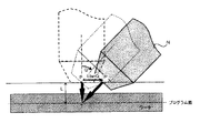
この切断面に傾斜を設けるためにノズルを傾斜させるとき、図1に示すように、ビーム等の照射点Tを中心にノズルNを傾斜させることにより、ビーム等の照射点と加工プログラム間との軌跡ずれが生じないようにしなければ、加工誤差が生じる。そのため、ビーム等の照射点Tを中心にノズルNを傾斜させN’の状態とすると、ノズルNとワークが接触することが考えられるため、大型の機械では、図2のようにノズル中心軸線に沿ってならい制御を行い、ノズルNを後方に逃がしている。又、コンパクトで安価に作成できるZ軸方向のみのならい制御機構を用いて、図3のように、Z軸方向にならい制御を行うことも行われている。
【0004】
又、ノズルを傾斜したときのビーム照射点のずれ量を、ノズル姿勢毎に予め測定し、それを補正量として記憶しておき、加工の際にノズルの姿勢が変化するとその姿勢に応じた補正量を読み出し、自動的に補正するようにしたレーザ加工機の工具補正方法も知られている(特許文献1参照)。
【0005】
【特許文献1】
特開2000−305613号公報(特に、請求項1参照)
【0006】
【発明が解決しようとする課題】
図2のようにならい制御をノズルNの中心軸線に沿って行う場合、ビーム等の照射点Tの軌跡が加工プログラムでの指令経路とズレることはないが、ノズル構造が複雑となるため機構が大きくなり、コストもかかるという欠点がある。又、図3のように、Z軸方向にならい制御を行うようにすれば、コンパクトで安価に構成できるが、ビーム等の照射点と加工プログラムとの間に軌跡ズレが発生し、プログラム指令通りの加工をすることができず、加工精度が低下する。
【0007】
また、静電容量形センサをノズル先端にノズルと同じ向きに取り付けてワーク面とノズル先端点間の距離を所定距離に保持しながらならい制御により加工する場合、ノズルが傾斜することによりセンサも傾斜しセンサの測定値に誤差が生じる。センサの測定誤差のため、ワークとノズル間が目標距離とならず、Z軸方向のならい制御による加工では、ビーム等の照射点と加工プログラムとの間に軌跡ズレが発生し、プログラム指令通りの加工物を得ることができないという問題がある。
【0008】
そこで、本発明の目的は、ノズルを傾けて加工するとき、簡単で容易にビーム照射点と加工プログラムとの間のズレを防止でき、ワークとノズルの干渉も防止するレーザ加工機、プラズマ加工機、ガス切断機の制御を行う数値制御装置を提供することにある。
【0009】
【課題を解決するための手段】
請求項1に係わる発明は、レーザ加工機、プラズマ加工機、ガス切断機等を制御する数値制御装置において、被加工ワークの表面と略平行なプログラム面に対する前記ノズルの姿勢が垂直で、ノズル先端点が前記プログラム面より所定距離隔たる位置の位置指令データで加工経路が教示された加工プログラムを記憶する手段と、前記ノズルの目標姿勢を指令する手段と、加工進行方向に垂直な面内で、レーザビーム、プラズマジェット又はガス噴射流等が向けられるプログラム面上の位置を固定したまま前記ノズルが前記目標姿勢となる位置から、さらに前記ノズルを該ノズルの中心軸線に沿って後方に、該ノズル先端と前記プログラム面との距離が前記所定距離となる位置を求め、該位置にノズル先端点を移動させ補正する位置補正手段と、を備えたことを特徴とする数値制御装置である。
【0010】
又、請求項2に係わる発明は、さらに、前記ノズルの目標姿勢、及び前記ノズルの先端と前記プログラム面間の目標距離を指令する手段を設けることにより、ノズルを傾斜したとき前記所定位置の代わりに指令された前記目標距離となる位置を求め、該位置にノズル先端点を移動させるようにしたものである。
【0011】
請求項3に係わる発明は、さらに、前記ノズルに設けられたワークまでの距離を測定するセンサと、ノズルの傾斜角とノズル先端点とプログラム面間の距離に対応して前記センサで測定される目標測定距離を求める手段と、前記位置補正手段による位置補正でのノズルの垂直状態からの傾斜角と前記所定距離若しくは目標距離より、前記目標測定距離を求める手段から目標測定距離を求め、該目標測定距離をならい制御における前記センサによる測定距離の目標値に変更する変更手段とを設けたものである。
【0012】
請求項4に係わる発明は、ノズル部にノズル先端点とワーク面間の距離を計測するセンサを備えたレーザ加工機、プラズマ加工機、ガス切断機等を制御する数値制御装置において、被加工ワークの表面と略平行なプログラム面に対する前記ノズルの姿勢が垂直で、ノズル先端点が前記プログラム面より所定距離隔たる位置の位置指令データで加工経路が教示された加工プログラムを記憶する手段と、前記ノズルの目標姿勢を指令する手段と、ノズルの傾斜角とノズル先端点とプログラム面間の距離に対応して前記センサで測定される目標測定距離を求める手段と、加工進行方向に垂直な面内で、レーザビーム、プラズマジェット又はガス噴射流等が向けられるプログラム面上の位置を固定したまま前記ノズルが前記目標姿勢へ移動すると共に、前記目標測定距離を求める手段より前記所定距離とノズル姿勢より前記センサで測定される目標測定距離を求め、該目標測定距離とセンサで計測される距離が一致するようにノズルをノズル中心軸線方向に移動させる制御手段と、を備えたことを特徴とする数値制御装置である。又、請求項5に係わる発明は、このノズル部にノズル先端点とワーク面間の距離を計測するセンサを備えたレーザ加工機、プラズマ加工機、ガス切断機等を制御する数値制御装置において、前記ノズルの目標姿勢、及び前記ノズルの先端と前記プログラム面間の目標距離を指令する手段を設けて、ノズルを傾斜したとき前記所定位置の代わりに指令された前記目標距離となる位置を求め、該位置にノズル先端点を移動させるようにしたものである。
【0013】
請求項6に係わる発明は、上述した各発明で使用されるセンサを静電容量型距離センサとしたものである。又、請求項7に係わる発明は、前記目標測定距離を求める手段を、ワークに対する前記センサ又は前記ノズルの傾きと、ワークと前記ノズル間の実際の距離に対する前記センサによる目標測定距離又は該目標測定距離に相当する物理量とで表したデータテーブルで構成したものである。請求項8に係わる発明はこのデータテーブルに代えて、ノズル先端点とプログラム面間の距離とワークに対する前記センサ又は前記ノズルの傾きにより、前記センサによる目標測定距離又は該目標測定距離に相当する物理量を求める式から演算する手段で構成したものである。
【0014】
【発明の実施の形態】
図4は、本発明の原理説明図である。被加工物であるワークと平行にプログラム面をとり、プログラム面に加工しようとする形状の加工プログラムを作成し加工機を制御する数値制御装置に設定入力されているものとする。そして、ノズル先端点Pとプログラム面との距離をLとして数値制御装置のメモリに記憶されているものとする。ノズル姿勢がワークに対して垂直な状態である場合、プログラム面でのビーム等の照射点Tと加工プログラムとの軌跡ズレはない。しかし、ノズルNが垂直状態からQ度傾斜する場合、前述したように、ビーム等の照射点Tと加工プログラムとの間にズレが生じるので、図4のように、ビーム等の照射点Tを中心にノズルNを傾斜させ、ノズル中心軸線に沿って後方に次の(1)式で示す補正距離Dだけノズル先端を移動させる。これによって、ノズル先端点Pとプログラム面との距離Lが一定に保持される。
【0015】
D=(L/cosQ−L) …(1)
図5は本発明の別の補正方法の原理説明図である。ノズル先端点Pを中心にノズルNを傾斜させ、かつ、X−Y平面内でノズル傾斜方向へ次の(2)式で示す補正距離D’だけノズル先端を移動させることによって、ビーム等の照射点Tの位置を変えずに、かつノズル先端点Pとプログラム面との距離Lを一定に保持させることができる。
【0016】
D’=(LtanQ) …(2)
本発明は、以上のようにして、プログラム面におけるビーム等の照射点Tと加工プログラムとの軌跡ずれを防止し、また、プログラム面とノズル先端の距離をLに保ったまま、ノズル姿勢を変化させるものである。
【0017】
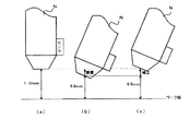
単に、ノズル姿勢を傾斜させて、ワーク切断面に傾斜をつけて加工を行うだけであれば、上述したような、ノズル先端点P位置を補正するだけでよい。しかし、ワーク面に対してノズル先端点Pが所定目標距離を保持して、プログラムされた指令経路をならって切断加工する場合、ノズルに取り付けたセンサによりワークまでの距離を測定し、該測定距離が目標距離と一致するようにならい制御する方法が取られている。この場合、ノズルを傾斜させることから、センサも傾斜することになり、測定距離が異なり、ならい制御の目標値を変えないと、ワークとノズル先端点間の距離(ギャップ)を目標値どおりに保持できなくなる。図6は、ノズル(センサ)を傾けたとき、このならい制御の目標値変更の説明図である。
【0018】
センサは、センサの傾きが0度のときの測定距離がワークとノズル間の実際の距離と一致するように調整されている。図6の(a)は、センサの傾きが0度の状態で、ワークとノズル間の目標距離を1.0mmにするため、センサの測定距離が1.0mmに収束するようにならい制御が行われている。
【0019】
図6の(b)は、(a)の状態からノズルが30度傾いた状態とすると、(a)と同様にセンサの測定距離が1.0mmに収束するようにならい制御が行われることによって、センサで測定するワーク面までの距離は垂直方向ではなくなることから、センサの測定距離が1.0mmであっても、例えば、(b)のように、ワークとノズル間の実際の距離は0.8mmになってしまう。測定誤差が発生している。
【0020】
図6の(c)に示すように、ノズル先端点とワーク面間の距離が所定目標距離の1.0mmとなるように補正する必要がある。そのために、本発明は、ならい制御のためにセンサで検出する距離の目標値をノズルの傾斜角に応じて、補正し修正するようにする。この修正目標値は、計算式を用いて演算して求めてもよいが、後述する本発明の実施形態では、図7に示すようなデータテーブルDTを設け、センサで検出される測定距離の目標値を変更することによって、ノズルNを傾斜したときでも、ノズル先端点とワーク間の距離を所定目標距離に保持できるようにするものである。
【0021】
図7のデータテーブルDTにおいて、「センサの測定距離」はセンサが測定し出力する距離(若しくは又は該距離に相当する物理量でもよい)であり、センサの傾きが「0度」の場合は、このセンサから出力される測定距離と実際のノズルの先端点とワーク面との距離(以下この距離をギャップという)は等しくなる。
しかしノズル及びセンサを傾けたとき、センサ出力の測定距離と実際のギャップ(ノズルの先端点とワーク面との距離)は異なることになる。そこで、各角度にノズル及びセンサを傾けて、そのときのセンサ測定距離と実際のギャップの対応をこのデータテーブルDTに記憶させておく。例えば、図7に示す例では、ノズル及びセンサを30度傾けたとき、センサで測定された距離が1.0mmのとき、実際のノズルの先端点とワーク面との距離のギャップは0.8mmである。又、センサの測定距離の出力が1.2mmのとき、ギャップ(実際のノズルの先端点とワーク面との距離)は1.0mmである。
【0022】
そこで、例えば、ギャップを1.0mmに保持してならい制御を行うとすれば、ノズル及びセンサを30度傾けたときには、センサ出力が1.2mmであれば、ギャップが1.0mmとなるから、ならい制御のための目標値を1.2mmにして制御すればよいものとなる。すなわち、ノズル及びセンサの傾き角度に対して設定ギャップに対応するセンサの測定距離をこのデータテーブルDTから読み出しならい制御のための目標値と設定すればよいものとなる。例えば、ギャップを1.0mmでならい制御する場合で、ノズル及びセンサの傾斜角が30度である場合、ギャップが1.0mmに対応するセンサ測定距離1.2mmをならい制御の目標値とすればよい。
【0023】
又、このデータテーブルDTに対応する傾斜角がない場合には、その傾斜角の両側のデータより補間してならい制御の目標値を設定する。例えば、ギャップ(ノズルの先端点とワーク面との距離)が1.0mmでデータテーブルDTに20度と30度のデータしかない場合には、20度と30度の間の傾斜角に対しては、20度及び30度のギャップが1.0mmに対応するセンサ測定距離を内挿することによって求める。
【0024】
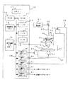
図8は本発明の一実施形態の数値制御装置を適用したレーザ加工機の概要図である。符号10はこのレーザ加工機を制御する制御装置であり、数値制御装置(CNC)で構成されている。該数値制御装置10は、プロセッサ(CPU)11を中心に構成され、該プロセッサ11にはバス24を介して、ROM12、RAM14,バッテリバックアップされたCMOSRAMで構成された不揮発性メモリ13、入出力インタフェース15,17、表示装置(CRTや液晶等)付きMDI(手動入力装置)16、加工送り軸のX軸,Y軸のサーボアンプ19,20、ギャップ制御軸のZ軸のサーボアンプ21、Z軸回りに加工ヘッド40を回転させる回転軸であるA軸のサーボアンプ22、Z軸に対して直交する軸回りの回転軸であるB軸のサーボアンプ23が接続されている。
【0025】
ROM12にはこのレーザ加工機30全体を制御するシステムプログラムが格納されており、不揮発性メモリ13には、表示装置付きMDI16を利用して作成される加工プログラム若しくは図示しない入力インタフェースを介して入力される加工プログラムが格納される。さらに、前述したノズルが傾斜したときのセンサ測定距離とギャップ(ノズル先端点とワーク面間の距離)の関係を記憶したデータテーブルDTが格納されている。また、RAM14は各種処理中におけるデータの一時記憶等に利用される。入出力インタフェース15にはレーザ発振器50が接続され、プロセッサ11からの出力制御信号を、該入出力インタフェース15を介してレーザ発振器50に送信する。レーザ発振器50は、出力制御信号に従ってレーザビーム51を出射し、ベンディングミラー52で反射して加工ヘッド40に送り、該加工ヘッド40で集光されて加工ヘッド40に取り付けられているノズル41の先端からレーザビーム51をワーク44に照射する。
【0026】
加工ヘッド40のノズル41には、加工ノズル41の先端点とワーク44間の距離(ギャップ)を測定するセンサ42が設けられており、該センサ42の出力信号は、制御装置10内のA/D変換器(アナログ信号をデジタル信号に変換する変換器)18を介して入出力インタフェース17に出力されている。
【0027】
また、符号37はレーザ加工機機構部で、該レーザ加工機機構部37には、ワーク44を取り付けたテーブル43をX軸方向(図8において左右方向)に駆動するX軸サーボモータ31、テーブル43をY軸方向(図8において紙面垂直方向)に駆動するY軸サーボモータ32、加工ヘッド40及びノズル41を上記X,Y軸方向に垂直なZ軸方向に駆動するギャップ制御軸を構成するZ軸サーボモータ33を備えている。さらに、Z軸サーボモータ33で駆動される可動部には、加工ヘッド40をZ軸回りに回転させるA軸サーボモータ34及び、Z軸に対して垂直な軸回りに加工ヘッド40を回転させるB軸サーボモータ35を備えている。
【0028】
X,Y軸サーボモータ31,32はテーブル43を駆動し、Z軸サーボモータ33は、ノズル41の先端点とワーク44間の距離、すなわちギャップを調整するために用いられ、A,B軸のサーボモータ34,35は、加工ヘッド40及びノズル41を傾斜させるために用いられる。
【0029】
X軸サーボモータ31は、数値制御装置10のX軸サーボアンプ19に接続され、Y軸サーボモータ32はY軸サーボアンプ20に接続され、Z軸サーボモータ33はZ軸サーボアンプ21に接続され、A軸サーボモータ34はA軸サーボアンプ22に接続され、B軸サーボモータ34はB軸サーボアンプ23に接続されている。また、各サーボモータ31,32,33,34,35には位置・速度を検出パルスコーダ等の位置速度検出器が取り付けられ、それぞれのサーボモータ31,32,33の位置、速度を各サーボアンプ19,20,21,22,23にフィードバックしている。また、各サーボアンプ19,20,21,22,23は、プロセッサ11からの指令と位置、速度のフィードバック信号に基づいて、各サーボモータ31,32,33の位置、速度を制御している。さらには、図示しない電流検出器のフィードバック信号に基づいて電流制御をも実施している。
【0030】
上述したレーザ加工機の構成は、従来から公知の、5軸構成で、加工ヘッド及びノズルを傾斜することが可能で、加工ノズルとワーク間のギャップ量が所定値になるように制御しながら、指令に従って加工ヘッドをワークに対して相対的に移動させて所定加工形状を加工する、いわゆるならい制御を実施するレーザ加工機と同一構成である。
このような、従来から公知の5軸構成のレーザ加工機で、本実施形態は加工ヘッド及びノズルを傾斜したときノズルとワークの干渉を防止するためにノズルを後退させる動作を簡単に行うことができるようにしたものである。
【0031】
加工開始前等の加工を停止している状態で、加工プログラム又はMDI16等から入力された指令で、加工ヘッド40及びノズル41を傾斜させる場合には、A軸、B軸のサーボモータ34,35を駆動して、予め設定されているノズル先端点Pとプログラム面間の距離Lによって求まるビーム照射点を中心に指令された角度Qだけ回転させ、かつ、前述した(1)式の演算で求められる補正距離Dだけノズル中心軸線方向に加工ヘッド及びノズルを後退させてギャップを所定値に保持すればよい。又、ノズル先端点を中心に指令された角度Qだけ回転させ、かつ、前述した(2)式の演算で求められる補正距離D’だけ傾斜方向に加工ヘッド及びノズルを後退させてギャップを所定値に保持すればよい。ならい制御の目標値も設定ギャップ量に対するセンサ測定距離に設定すればよい。
【0032】
一方、加工途中で、加工ヘッド40及びノズル41を傾斜させて開先加工を行うような場合には、A軸、B軸のサーボモータ34,35を駆動して加工ヘッド40及びノズル41を指令角度Qに達するまで、指令速度で傾斜させながら、かつその傾斜に応じて、補正距離D又はD’移動させるようにX,Y,Z軸の移動指令に重畳させて補正する。
【0033】
図9は、数値制御装置10のプロセッサ11が補間周期毎に実行する処理のフローチャートである。
加工プログラム等で指令されている加工速度、指令位置、さらには傾斜指令がある場合には、指令傾斜速度、指令傾斜角に基づいてX,Y,A,B軸への補間周期間における分配移動量を求める(ステップ100)。なお、Z軸に対してはセンサ42で検出されたギャップが設定値に保持するように、ギャップ制御を行ってその移動量を求める。
【0034】
次に傾斜軸であるA,B軸への分配移動量があるか否か判断し(ステップ101)、該分配移動量がある場合には傾斜指令があったときであり、分配移動量がない場合には、傾斜指令がないものであり、この場合には、ステップ106に移行して、ステップ100で求めた各軸への分配移動量をX,Y,Z軸のサーボアンプ19,20,21に出力し、当該分配周期の処理を終了する。X,Y,Z軸のサーボアンプ19,20,21はこの分配移動量を受けて、位置、速度さらには電流のループ制御を行いX,Y,Z軸のサーボモータ31,32,33を駆動制御してテーブル43,ワーク44を移動させ、レーザビーム51で切断加工する。
【0035】
一方、ステップ101で、傾斜軸への分配移動量が検出され傾斜指令がある場合には、この傾斜軸への分配移動量への積算値に基づいて、当該分配周期での傾斜角Qを求め、該傾斜角Qに対する位置補正量D(なお、この実施形態では、ビーム照射点を中心に傾斜させるものとする)を求め、前周期の位置補正量を減じて当該周期における補正量とする(ステップ102)。この補正量をX,Y,Z軸方向に分解し(ステップ103)、ステップ100で求めた、各軸分配移動量にこの補正量の各軸成分量を重畳し、補正された各軸分配移動量を求める(ステップ104)。さらに、当該周期における傾斜角Qに対するセンサ目標値をデータテーブルDTより読み出し、又は該データテーブルDTに記憶するデータから補間して求め、ならい制御の目標値を変更する(ステップ105)。
【0036】
そして、ステップ104で求めた補正されたX,Y,Z軸分配移動量とステップ100で求めたA,B軸の分配移動量を各軸サーボアンプ19〜23に出力し当該周期の処理を終了する。
以下傾斜角が指令傾斜角になるまで、ステップ100〜106の処理を補間周期毎実行し、傾斜角が指令角度になり、傾斜軸のA,B軸に対して分配移動量がなくなると、ステップ100、101,106の処理に切り替わる。
【0037】
なお、上述した実施形態では、ビーム照射点を中心に加工ヘッド40及びノズル41を傾斜させたが、ノズル先端点を中心に傾斜させる場合には、ステップ102で求める補正量は(2)式の演算によって求めた位置補正量D’を用いることになる。
【0038】
又、上述した説明では、ノズル先端点とプログラム面間の距離L(ギャップ量+プログラム面とワーク面間の距離)を、ノズルを傾斜したときもノズルを傾斜させないときと同一にして加工を行うものとした。これは、ノズルとワークが干渉することを避けるためのものである。しかし、ノズルを傾斜しても、所定ギャップ量(ノズル先端点とワーク面間の距離)まで、干渉が生じないような場合など、ノズルを傾斜して加工するときに、プログラムで又は、パラメータ等の設定でギャップ量(又はノズル先端点とプログラム面間の距離L)を設定してもよい。
【0039】
さらに、上述した実施形態では、ノズルを傾斜したとき、その傾斜角に応じて、ならい制御のセンサ測定値の目標値をデータテーブルDTによって求めるようにしたが、この目標値を演算によって求めてもよい。ノズルを傾けずに垂直状態で設定ギャップ量のときセンサで測定される測定値がLであったとする。ノズルを角度Q傾けて、ギャップ量を傾ける前の同じ量とすれば、センサで測定される距離は「L/cosQ」となる。よって、傾斜角Qによりならい制御によるセンサ測定値の目標値をL/cosQの演算を行うことによって求める。すなわち、
目標値=L/cosQ
として演算によって求めるようにしてもよい。
【0040】
さらに、センサ出力を利用して、ノズルを後退させるようにしてもよい。この場合、ノズルの傾斜角度Qによって、ノズルの中心軸線方向が決まるので、ノズルを傾斜させた後、センサから出力される計測距離が、設定ノズル先端点とプログラム面間の距離Lとプログラム面とワーク面間の距離によって求まるギャップ量に対応するその傾斜角度における計測距離になるまで、ノズルの中心軸線方向にノズルを後退させればよい。
【0041】
なお、上述した実施形態では、レーザ加工機に本発明を適用した例を説明したが、レーザ加工機以外の、プラズマ加工機、ガス切断機等のノズル先端位置固定制御を有する加工機にも、レーザ加工機がプラズマ加工機やガス切断機に代わるだけで、上述した構成内容で本発明は適用できるものである。
【0042】
【発明の効果】
レーザ加工機、プラズマ加工機、ガス切断機等における開先加工において、ノズル方向へのならい制御機構を持たない機械においても、ノズル先端位置に補正をかけることにより、被加工ワーク表面と略平行なプログラム面で軌跡ずれのない加工を実現することができる。
【図面の簡単な説明】
【図1】レーザ加工機、プラズマ加工機、ガス切断機等において、ノズルを傾けて加工するときのノズルとワークの干渉を説明する説明図である。
【図2】ノズル中心軸線に沿ってならい制御を行ってノズルとワークの干渉をなくした従来の方法の説明図である。
【図3】Z軸方向にならい制御を行って、簡易的にノズルとワークの干渉をなくした従来の方法の説明図である。
【図4】ノズルを傾けて加工するときのノズルとワークの干渉を避ける本発明の原理説明図である。
【図5】ノズルを傾けて加工するときのノズルとワークの干渉を避ける本発明の別の方法の原理説明図である。
【図6】ノズルを傾けたときのならい制御の目標値変更の説明図である。
【図7】ノズルを傾けたときのならい制御の目標値を変更するためのデータテーブルの説明図である。
【図8】本発明をレーザ加工機に適用した一実施形態の要部ブロック図である。
【図9】同実施形態における補間周期での処理のフローチャートである。
【符号の説明】
N,41 ノズル
T ビーム等の照射点
10 数値制御装置
30 レーザ加工機
31,32,33,34,35 サーボモータ
43 テーブル
44 ワーク[0001]
BACKGROUND OF THE INVENTION
The present invention relates to a processing machine having a mechanism capable of changing a nozzle attitude, and more particularly, to a numerical control device for controlling a laser processing machine, a plasma processing machine, a gas cutting machine, etc. that perform groove processing for inclining a workpiece cutting surface.
[0002]
[Prior art]
In a processing machine having nozzle tip position fixing control, such as a laser processing machine, a plasma processing machine, and a gas cutting machine, a processing program surface is provided for a workpiece to be processed, and on a path programmed in the processing program surface, Control is performed so that a point to which a laser beam, a plasma jet, a gas jet flow or the like is directed (hereinafter referred to as an irradiation point of a beam or the like) passes. In addition, when performing groove processing for inclining the workpiece cutting surface, the cutting is performed by inclining the cutting surface by inclining the nozzle from a vertical state with respect to the workpiece. Further, the inclination of the cut surface is changed with the progress of processing by gradually changing the nozzle posture during processing.
[0003]
When the nozzle is tilted in order to provide an inclination to the cut surface, as shown in FIG. 1, the nozzle N is tilted around the irradiation point T of the beam or the like, so that the irradiation point between the beam and the processing program is If the locus deviation is not prevented, a machining error occurs. Therefore, if the nozzle N is tilted around the irradiation point T such as a beam to be in the N ′ state, it is conceivable that the nozzle N and the workpiece come into contact with each other. Therefore, in a large machine, as shown in FIG. Along the way, the nozzle N is released backward. Further, as shown in FIG. 3, control is also performed in the Z-axis direction using a control mechanism that is only compact in the Z-axis direction and can be produced at low cost.
[0004]
Also, the deviation amount of the beam irradiation point when the nozzle is tilted is measured in advance for each nozzle posture and stored as a correction amount. If the posture of the nozzle changes during processing, correction according to the posture is performed. A tool correction method for a laser beam machine that reads out the amount and automatically corrects the amount is also known (see Patent Document 1).
[0005]
[Patent Document 1]
Japanese Unexamined Patent Publication No. 2000-305613 (in particular, refer to claim 1)
[0006]
[Problems to be solved by the invention]
When the control similar to that shown in FIG. 2 is performed along the central axis of the nozzle N, the locus of the irradiation point T such as a beam does not deviate from the command path in the machining program. There is a disadvantage that it is large and expensive. In addition, as shown in FIG. 3, if the control is performed in the Z-axis direction, a compact and inexpensive configuration can be realized. However, a locus shift occurs between the irradiation point of the beam and the machining program, and the program command is given. Can not be processed, the processing accuracy is reduced.
[0007]
In addition, when a capacitance type sensor is attached to the nozzle tip in the same direction as the nozzle and the workpiece is processed by the profile control while maintaining the distance between the workpiece surface and the nozzle tip point at a predetermined distance, the sensor tilts as the nozzle tilts. However, an error occurs in the measured value of the sensor. Due to the measurement error of the sensor, the distance between the workpiece and the nozzle does not become the target distance, and in machining by profile control in the Z-axis direction, a locus deviation occurs between the irradiation point of the beam etc. and the machining program, There is a problem that a workpiece cannot be obtained.
[0008]
Accordingly, an object of the present invention is to provide a laser processing machine and a plasma processing machine that can easily and easily prevent a deviation between a beam irradiation point and a processing program and prevent interference between a workpiece and a nozzle when processing with the nozzle tilted. Another object of the present invention is to provide a numerical control device that controls a gas cutting machine.
[0009]
[Means for Solving the Problems]
The invention according to
[0010]
Further, the invention according to
[0011]
The invention according to
[0012]
According to a fourth aspect of the present invention, there is provided a numerical control apparatus for controlling a laser processing machine, a plasma processing machine, a gas cutting machine, or the like provided with a sensor for measuring a distance between a nozzle tip point and a work surface in a nozzle portion. Means for storing a machining program in which a machining path is taught by position command data at a position where the nozzle posture is perpendicular to a program plane substantially parallel to the surface of the nozzle and the nozzle tip point is separated from the program plane by a predetermined distance; Means for instructing the target posture of the nozzle, means for obtaining a target measurement distance measured by the sensor corresponding to the inclination angle of the nozzle, the nozzle tip point, and the distance between the program surfaces, and an in-plane perpendicular to the machining progress direction The nozzle moves to the target posture while the position on the program surface to which the laser beam, plasma jet or gas jet flow is directed is fixed. The target measurement distance measured by the sensor is obtained from the predetermined distance and the nozzle attitude from the means for obtaining the target measurement distance, and the nozzle is moved in the nozzle center axis direction so that the target measurement distance and the distance measured by the sensor coincide with each other. And a control means for moving the numerical control device. The invention according to
[0013]
In the invention according to claim 6, the sensor used in each of the above-described inventions is a capacitance type distance sensor. Further, in the invention according to
[0014]
DETAILED DESCRIPTION OF THE INVENTION
FIG. 4 is a diagram illustrating the principle of the present invention. It is assumed that a program surface is taken in parallel with a workpiece that is a workpiece, a machining program having a shape to be machined into the program surface is created, and set and input to a numerical control device that controls the processing machine. It is assumed that the distance between the nozzle tip point P and the program surface is stored as L in the memory of the numerical controller. When the nozzle posture is perpendicular to the workpiece, there is no locus shift between the irradiation point T such as a beam on the program surface and the machining program. However, when the nozzle N is tilted by Q degrees from the vertical state, as described above, a deviation occurs between the irradiation point T of the beam and the machining program, so that the irradiation point T of the beam or the like is changed as shown in FIG. The nozzle N is inclined at the center, and the nozzle tip is moved backward along the nozzle center axis by the correction distance D shown by the following equation (1). Thereby, the distance L between the nozzle tip point P and the program surface is kept constant.
[0015]
D = (L / cosQ−L) (1)
FIG. 5 is an explanatory diagram of the principle of another correction method of the present invention. Irradiation of a beam or the like is performed by tilting the nozzle N around the nozzle tip point P and moving the nozzle tip by the correction distance D ′ shown in the following equation (2) in the nozzle tilt direction in the XY plane. It is possible to keep the distance L between the nozzle tip point P and the program surface constant without changing the position of the point T.
[0016]
D ′ = (LtanQ) (2)
As described above, the present invention prevents the deviation of the locus between the irradiation point T of the beam on the program surface and the machining program, and changes the nozzle posture while keeping the distance between the program surface and the nozzle tip at L. It is something to be made.
[0017]
If the machining is performed simply by inclining the nozzle posture and inclining the workpiece cutting surface, it is only necessary to correct the nozzle tip point P position as described above. However, when the nozzle tip point P holds a predetermined target distance with respect to the work surface and cuts along a programmed command path, the distance to the work is measured by a sensor attached to the nozzle, and the measured distance A control method is adopted in which the control is performed in accordance with the target distance. In this case, since the nozzle is tilted, the sensor is also tilted, the measurement distance is different, and if the target value of the profile control is not changed, the distance (gap) between the workpiece and the nozzle tip point is maintained as the target value. become unable. FIG. 6 is an explanatory diagram of the change of the target value of the follow-up control when the nozzle (sensor) is tilted.
[0018]
The sensor is adjusted so that the measurement distance when the inclination of the sensor is 0 degree matches the actual distance between the workpiece and the nozzle. In FIG. 6A, in order to set the target distance between the workpiece and the nozzle to 1.0 mm in a state where the inclination of the sensor is 0 degree, control is performed so that the measurement distance of the sensor converges to 1.0 mm. It has been broken.
[0019]
FIG. 6B shows that when the nozzle is tilted 30 degrees from the state of FIG. 6A, the control distance is controlled so that the measurement distance of the sensor converges to 1.0 mm as in FIG. Since the distance to the workpiece surface measured by the sensor is not in the vertical direction, even if the measurement distance of the sensor is 1.0 mm, for example, as shown in (b), the actual distance between the workpiece and the nozzle is 0. .8mm. A measurement error has occurred.
[0020]
As shown in FIG. 6C, it is necessary to correct the distance between the nozzle tip point and the work surface so as to be a predetermined target distance of 1.0 mm. For this purpose, the present invention corrects and corrects the target value of the distance detected by the sensor for profile control according to the inclination angle of the nozzle. The corrected target value may be obtained by calculation using a calculation formula. However, in an embodiment of the present invention described later, a data table DT as shown in FIG. 7 is provided, and the target of the measurement distance detected by the sensor. By changing the value, even when the nozzle N is inclined, the distance between the nozzle tip point and the workpiece can be maintained at a predetermined target distance.
[0021]
In the data table DT of FIG. 7, the “sensor measurement distance” is a distance measured by the sensor (or a physical quantity corresponding to the distance), and when the sensor inclination is “0 degree”, The measurement distance output from the sensor is equal to the distance between the actual nozzle tip and the workpiece surface (hereinafter, this distance is referred to as the gap).
However, when the nozzle and the sensor are tilted, the measured distance of the sensor output and the actual gap (distance between the tip of the nozzle and the work surface) are different. Therefore, the nozzle and the sensor are inclined at each angle, and the correspondence between the sensor measurement distance and the actual gap at that time is stored in this data table DT. For example, in the example shown in FIG. 7, when the nozzle and sensor are tilted 30 degrees, and the distance measured by the sensor is 1.0 mm, the gap between the actual nozzle tip and the workpiece surface is 0.8 mm. It is. When the sensor measurement distance output is 1.2 mm, the gap (the actual distance between the tip of the nozzle and the workpiece surface) is 1.0 mm.
[0022]
Therefore, for example, if the control is performed while maintaining the gap at 1.0 mm, when the nozzle and the sensor are tilted by 30 degrees, if the sensor output is 1.2 mm, the gap becomes 1.0 mm. The target value for the profile control may be controlled to 1.2 mm. That is, the sensor measurement distance corresponding to the set gap with respect to the inclination angle of the nozzle and the sensor may be set as a target value for control that is read from the data table DT. For example, when the gap is controlled by 1.0 mm and the nozzle and sensor tilt angle is 30 degrees, the sensor measurement distance of 1.2 mm corresponding to the gap of 1.0 mm is set as the target value for the control. Good.
[0023]
If there is no inclination angle corresponding to this data table DT, a control target value is set by interpolation from data on both sides of the inclination angle. For example, if the gap (distance between the nozzle tip and the work surface) is 1.0 mm and the data table DT contains only data of 20 degrees and 30 degrees, for an inclination angle between 20 degrees and 30 degrees Is determined by interpolating sensor measurement distances corresponding to gaps of 20 and 30 degrees of 1.0 mm.
[0024]
FIG. 8 is a schematic view of a laser processing machine to which the numerical control device of one embodiment of the present invention is applied. Reference numeral 10 denotes a control device that controls the laser processing machine, and is constituted by a numerical control device (CNC). The numerical control device 10 is mainly composed of a processor (CPU) 11, and the processor 11 is connected to a
[0025]
The
[0026]
The nozzle 41 of the
[0027]
[0028]
The X and Y axis servo motors 31 and 32 drive the table 43, and the Z axis servo motor 33 is used to adjust the distance between the tip of the nozzle 41 and the workpiece 44, that is, the gap. The
[0029]
The X-axis servo motor 31 is connected to the
[0030]
The configuration of the laser processing machine described above is a conventionally known five-axis configuration, and it is possible to tilt the processing head and nozzle, while controlling the gap amount between the processing nozzle and the workpiece to be a predetermined value, It has the same configuration as a laser processing machine that performs so-called profile control in which a machining head is moved relative to a workpiece in accordance with a command to machine a predetermined machining shape.
In such a conventionally known 5-axis laser processing machine, this embodiment can easily perform the operation of retracting the nozzle to prevent interference between the nozzle and the workpiece when the processing head and the nozzle are inclined. It is something that can be done.
[0031]
When the
[0032]
On the other hand, in the case where groove processing is performed while the
[0033]
FIG. 9 is a flowchart of processing executed by the processor 11 of the numerical controller 10 for each interpolation cycle.
When there is a machining speed and command position commanded by a machining program, etc., and there is a tilt command, distributed movement during the interpolation cycle to the X, Y, A, and B axes based on the command tilt speed and command tilt angle An amount is determined (step 100). For the Z-axis, gap control is performed so that the gap detected by the sensor 42 is held at the set value, and the amount of movement is obtained.
[0034]
Next, it is determined whether or not there is a distribution movement amount to the A and B axes, which are the tilt axes (step 101). If there is a distribution movement amount, there is an inclination command, and there is no distribution movement amount. In this case, there is no tilt command. In this case, the process proceeds to step 106, and the distribution movement amount to each axis obtained in
[0035]
On the other hand, if the distribution movement amount to the tilt axis is detected and there is a tilt command in
[0036]
Then, the corrected X, Y, and Z-axis distributed movement amounts obtained in
Thereafter, the processing in
[0037]
In the above-described embodiment, the
[0038]
Further, in the above description, the distance L between the nozzle tip and the program surface (gap amount + distance between the program surface and the work surface) is set to be the same as when the nozzle is not tilted even when the nozzle is tilted. It was supposed to be. This is to avoid interference between the nozzle and the workpiece. However, when machining with tilted nozzles, such as when interference does not occur up to a predetermined gap amount (distance between the nozzle tip and workpiece surface) even when the nozzle is tilted, the program or parameters, etc. In this setting, the gap amount (or the distance L between the nozzle tip point and the program surface) may be set.
[0039]
Further, in the above-described embodiment, when the nozzle is tilted, the target value of the sensor measurement value of the follow control is obtained from the data table DT according to the tilt angle. However, the target value may be obtained by calculation. Good. It is assumed that the measured value measured by the sensor is L when the set gap amount is vertical without tilting the nozzle. If the nozzle is tilted at an angle Q and the same amount before the gap is tilted, the distance measured by the sensor is “L / cosQ”. Therefore, the target value of the sensor measurement value by the control following the inclination angle Q is obtained by calculating L / cosQ. That is,
Target value = L / cosQ
May be obtained by calculation.
[0040]
Further, the nozzle may be retracted using the sensor output. In this case, since the central axis direction of the nozzle is determined by the nozzle tilt angle Q, after the nozzle is tilted, the measurement distance output from the sensor is the distance L between the set nozzle tip point and the program surface, and the program surface. The nozzle may be retracted in the direction of the central axis of the nozzle until the measured distance at the tilt angle corresponding to the gap amount determined by the distance between the work surfaces.
[0041]
In the above-described embodiment, an example in which the present invention is applied to a laser processing machine has been described. However, other than a laser processing machine, a processing machine having nozzle tip position fixing control, such as a plasma processing machine or a gas cutting machine, The present invention can be applied with the above-described configuration only by replacing the laser processing machine with a plasma processing machine or a gas cutting machine.
[0042]
【The invention's effect】
In the groove processing in laser processing machines, plasma processing machines, gas cutting machines, etc., even in machines that do not have a control mechanism in the nozzle direction, by correcting the nozzle tip position, it is approximately parallel to the workpiece surface. Machining without trajectory deviation on the program side can be realized.
[Brief description of the drawings]
BRIEF DESCRIPTION OF DRAWINGS FIG. 1 is an explanatory diagram for explaining interference between a nozzle and a workpiece when processing is performed with an inclined nozzle in a laser processing machine, a plasma processing machine, a gas cutting machine or the like.
FIG. 2 is an explanatory diagram of a conventional method in which interference between the nozzle and the workpiece is eliminated by performing control along the nozzle center axis.
FIG. 3 is an explanatory diagram of a conventional method in which control following the Z-axis direction is performed to easily eliminate the interference between the nozzle and the workpiece.
FIG. 4 is an explanatory diagram of the principle of the present invention that avoids interference between the nozzle and the workpiece when machining with the nozzle tilted.
FIG. 5 is a diagram illustrating the principle of another method of the present invention for avoiding interference between a nozzle and a workpiece when machining with the nozzle inclined.
FIG. 6 is an explanatory diagram of target value change of the profile control when the nozzle is tilted.
FIG. 7 is an explanatory diagram of a data table for changing the target value of the profile control when the nozzle is tilted.
FIG. 8 is a main part block diagram of an embodiment in which the present invention is applied to a laser beam machine.
FIG. 9 is a flowchart of processing in an interpolation cycle in the same embodiment.
[Explanation of symbols]
N, 41 nozzles
Irradiation point such as T-beam
10 Numerical controller
30 Laser processing machine
31, 32, 33, 34, 35 Servo motor
43 tables
44 work
Claims (8)
被加工ワークの表面と略平行なプログラム面に対する前記ノズルの姿勢が垂直で、ノズル先端点が前記プログラム面より所定距離隔たる位置の位置指令データで加工経路が教示された加工プログラムを記憶する手段と、
前記ノズルの目標姿勢を指令する手段と、
加工進行方向に垂直な面内で、レーザビーム、プラズマジェット又はガス噴射流等が向けられるプログラム面上の位置を固定したまま前記ノズルが前記目標姿勢となる位置から、さらに前記ノズルを該ノズルの中心軸線に沿って後方に、該ノズル先端と前記プログラム面との距離が前記所定距離となる位置を求め、該位置にノズル先端点を移動させ補正する位置補正手段と、
を備えたことを特徴とする数値制御装置。In numerical control devices that control laser processing machines, plasma processing machines, gas cutting machines, etc.
Means for storing a machining program in which a machining path is taught by position command data at a position where the posture of the nozzle is perpendicular to a program surface substantially parallel to the surface of the workpiece and the nozzle tip point is separated from the program surface by a predetermined distance. When,
Means for commanding a target posture of the nozzle;
The nozzle is further moved from the position where the nozzle assumes the target posture while fixing the position on the program surface to which the laser beam, plasma jet or gas jet flow is directed in a plane perpendicular to the processing progress direction. A position correcting means for obtaining a position where the distance between the nozzle tip and the program surface is the predetermined distance, and moving the nozzle tip point to the position and correcting the position backward along the central axis;
A numerical control device comprising:
被加工ワークの表面と略平行なプログラム面に対する前記ノズルの姿勢が垂直で、ノズル先端点が前記プログラム面より所定距離隔たる位置の位置指令データで加工経路が教示された加工プログラムを記憶する手段と、
前記ノズルの目標姿勢、及び前記ノズルの先端と前記プログラム面間の目標距離を指令する手段と、
加工進行方向に垂直な面内で、レーザビーム、プラズマジェット又はガス噴射流等が向けられるプログラム面上の位置を固定したまま前記ノズルが前記目標姿勢となる位置から、さらに前記ノズルを該ノズルの中心軸線に沿って後方に、該ノズル先端と前記プログラム面との距離が前記目標距離となる位置を求め、該位置にノズル先端点を移動させ補正する位置補正手段と、
を備えたことを特徴とする数値制御装置。In numerical control devices that control laser processing machines, plasma processing machines, gas cutting machines, etc.
Means for storing a machining program in which a machining path is taught by position command data at a position where the posture of the nozzle is perpendicular to a program surface substantially parallel to the surface of the workpiece and the nozzle tip point is separated from the program surface by a predetermined distance. When,
Means for commanding a target posture of the nozzle and a target distance between the tip of the nozzle and the program surface;
The nozzle is further moved from the position where the nozzle assumes the target posture while fixing the position on the program surface to which the laser beam, plasma jet or gas jet flow is directed in a plane perpendicular to the processing progress direction. A position correcting means for obtaining a position where the distance between the nozzle tip and the program surface is the target distance, and moving and correcting the nozzle tip point to the position, along the center axis; and
A numerical control device comprising:
ノズルの傾斜角とノズル先端点とプログラム面間の距離に対応して前記センサで測定される目標測定距離を求める手段と、
前記位置補正手段による位置補正でのノズルの垂直状態からの傾斜角と前記所定距離若しくは目標距離より、前記目標測定距離を求める手段から目標測定距離を求め、該目標測定距離をならい制御における前記センサによる測定距離の目標値に変更する変更手段と、
を備える請求項1又は請求項2に記載の数値制御装置。A sensor for measuring the distance to the workpiece provided in the nozzle;
Means for determining a target measurement distance measured by the sensor in correspondence with a nozzle inclination angle, a nozzle tip point, and a distance between program surfaces;
The target measurement distance is obtained from means for obtaining the target measurement distance from the inclination angle of the nozzle from the vertical state in the position correction by the position correction means and the predetermined distance or the target distance, and the sensor in the control following the target measurement distance Change means for changing to the target value of the measurement distance by
The numerical control apparatus according to claim 1 or claim 2, further comprising:
被加工ワークの表面と略平行なプログラム面に対する前記ノズルの姿勢が垂直で、ノズル先端点が前記プログラム面より所定距離隔たる位置の位置指令データで加工経路が教示された加工プログラムを記憶する手段と、
前記ノズルの目標姿勢を指令する手段と、
ノズルの傾斜角とノズル先端点とプログラム面間の距離に対応して前記センサで測定される目標測定距離を求める手段と、
加工進行方向に垂直な面内で、レーザビーム、プラズマジェット又はガス噴射流等が向けられるプログラム面上の位置を固定したまま前記ノズルが前記目標姿勢へ移動すると共に、前記目標測定距離を求める手段より前記所定距離とノズル姿勢より前記センサで測定される目標測定距離を求め、該目標測定距離とセンサで計測される距離が一致するようにノズルをノズル中心軸線方向に移動させる制御手段と、
を備えたことを特徴とする数値制御装置。In a numerical control device that controls a laser processing machine, a plasma processing machine, a gas cutting machine, etc. equipped with a sensor that measures the distance between the nozzle tip point and the work surface in the nozzle part,
Means for storing a machining program in which a machining path is taught by position command data at a position where the posture of the nozzle is perpendicular to a program surface substantially parallel to the surface of the workpiece and the nozzle tip point is separated from the program surface by a predetermined distance. When,
Means for commanding a target posture of the nozzle;
Means for determining a target measurement distance measured by the sensor in correspondence with a nozzle inclination angle, a nozzle tip point, and a distance between program surfaces;
Means for determining the target measurement distance while moving the nozzle to the target posture while fixing the position on the program surface to which the laser beam, plasma jet, gas jet flow or the like is directed in a plane perpendicular to the processing advancing direction A control unit that obtains a target measurement distance measured by the sensor from the predetermined distance and the nozzle attitude, and moves the nozzle in the nozzle central axis direction so that the target measurement distance and the distance measured by the sensor coincide;
A numerical control device comprising:
被加工ワークの表面と略平行なプログラム面に対する前記ノズルの姿勢が垂直で、ノズル先端点が前記プログラム面より所定距離隔たる位置の位置指令データで加工経路が教示された加工プログラムを記憶する手段と、
前記ノズルの目標姿勢、及び前記ノズルの先端と前記プログラム面間の目標距離を指令する手段と、
ノズルの傾斜角とノズル先端点とプログラム面間の距離に対応して前記センサで測定される目標測定距離を求める手段と、
加工進行方向に垂直な面内で、レーザビーム、プラズマジェット又はガス噴射流等が向けられるプログラム面上の位置を固定したまま前記ノズルが前記目標姿勢へ移動すると共に、前記目標測定距離を求める手段より前記目標距離とノズル姿勢より前記センサで測定される目標測定距離を求め、該目標測定距離とセンサで計測される距離が一致するようにノズルをノズル中心軸線方向に移動させる制御手段と、
を備えたことを特徴とする数値制御装置。In a numerical control device that controls a laser processing machine, a plasma processing machine, a gas cutting machine, etc. equipped with a sensor that measures the distance between the nozzle tip point and the work surface in the nozzle part,
Means for storing a machining program in which a machining path is taught by position command data at a position where the posture of the nozzle is perpendicular to a program surface substantially parallel to the surface of the workpiece and the nozzle tip point is separated from the program surface by a predetermined distance. When,
Means for commanding a target posture of the nozzle and a target distance between the tip of the nozzle and the program surface;
Means for determining a target measurement distance measured by the sensor in correspondence with a nozzle inclination angle, a nozzle tip point, and a distance between program surfaces;
Means for determining the target measurement distance while moving the nozzle to the target posture while fixing the position on the program surface to which the laser beam, plasma jet, gas jet flow or the like is directed in a plane perpendicular to the processing advancing direction A control means for obtaining a target measurement distance measured by the sensor from the target distance and the nozzle attitude, and moving the nozzle in the nozzle central axis direction so that the target measurement distance and the distance measured by the sensor coincide with each other;
A numerical control device comprising:
Priority Applications (1)
| Application Number | Priority Date | Filing Date | Title |
|---|---|---|---|
| JP2002345950A JP3829114B2 (en) | 2002-11-28 | 2002-11-28 | Numerical controller |
Applications Claiming Priority (1)
| Application Number | Priority Date | Filing Date | Title |
|---|---|---|---|
| JP2002345950A JP3829114B2 (en) | 2002-11-28 | 2002-11-28 | Numerical controller |
Publications (2)
| Publication Number | Publication Date |
|---|---|
| JP2004174586A true JP2004174586A (en) | 2004-06-24 |
| JP3829114B2 JP3829114B2 (en) | 2006-10-04 |
Family
ID=32707004
Family Applications (1)
| Application Number | Title | Priority Date | Filing Date |
|---|---|---|---|
| JP2002345950A Expired - Lifetime JP3829114B2 (en) | 2002-11-28 | 2002-11-28 | Numerical controller |
Country Status (1)
| Country | Link |
|---|---|
| JP (1) | JP3829114B2 (en) |
Cited By (9)
| Publication number | Priority date | Publication date | Assignee | Title |
|---|---|---|---|---|
| JP2009053010A (en) * | 2007-08-27 | 2009-03-12 | Panasonic Corp | Dispensing device |
| WO2011114843A1 (en) * | 2010-03-17 | 2011-09-22 | シチズンホールディングス株式会社 | Machine tool |
| CN102658412A (en) * | 2012-05-07 | 2012-09-12 | 盈都桥梁钢构工程有限公司 | Hole opening process by numerical control cutting machine |
| JP2012196685A (en) * | 2011-03-18 | 2012-10-18 | Nissan Tanaka Corp | Nozzle for laser machining, control method and program for laser machining apparatus and laser machining apparatus |
| JP2017192970A (en) * | 2016-04-21 | 2017-10-26 | ファナック株式会社 | Laser processing apparatus and laser processing method |
| US10953543B2 (en) | 2018-03-22 | 2021-03-23 | Fanuc Corporation | Operation program setting apparatus for robot, robot, and method of controlling robot |
| WO2021200471A1 (en) * | 2020-03-30 | 2021-10-07 | ファナック株式会社 | Control device for laser machining apparatus |
| CN114952026A (en) * | 2022-03-22 | 2022-08-30 | 大族激光科技产业集团股份有限公司 | Groove cutting compensation method, computer readable storage medium and machining device |
| US11612963B2 (en) | 2018-03-26 | 2023-03-28 | Panasonic Intellectual Property Management Co., Ltd. | Laser cutting device including machining condition tables and laser cutting method thereof |
-
2002
- 2002-11-28 JP JP2002345950A patent/JP3829114B2/en not_active Expired - Lifetime
Cited By (15)
| Publication number | Priority date | Publication date | Assignee | Title |
|---|---|---|---|---|
| JP2009053010A (en) * | 2007-08-27 | 2009-03-12 | Panasonic Corp | Dispensing device |
| US9254543B2 (en) | 2010-03-17 | 2016-02-09 | Citizen Holdings Co., Ltd. | Machine tool |
| WO2011114843A1 (en) * | 2010-03-17 | 2011-09-22 | シチズンホールディングス株式会社 | Machine tool |
| JP2011192232A (en) * | 2010-03-17 | 2011-09-29 | Citizen Holdings Co Ltd | Machine tool |
| CN102804088A (en) * | 2010-03-17 | 2012-11-28 | 西铁城控股株式会社 | Machine tool |
| JP2012196685A (en) * | 2011-03-18 | 2012-10-18 | Nissan Tanaka Corp | Nozzle for laser machining, control method and program for laser machining apparatus and laser machining apparatus |
| CN102658412A (en) * | 2012-05-07 | 2012-09-12 | 盈都桥梁钢构工程有限公司 | Hole opening process by numerical control cutting machine |
| JP2017192970A (en) * | 2016-04-21 | 2017-10-26 | ファナック株式会社 | Laser processing apparatus and laser processing method |
| US11559851B2 (en) | 2016-04-21 | 2023-01-24 | Fanuc Corporation | Laser machining device and laser machining method |
| US10953543B2 (en) | 2018-03-22 | 2021-03-23 | Fanuc Corporation | Operation program setting apparatus for robot, robot, and method of controlling robot |
| US11612963B2 (en) | 2018-03-26 | 2023-03-28 | Panasonic Intellectual Property Management Co., Ltd. | Laser cutting device including machining condition tables and laser cutting method thereof |
| WO2021200471A1 (en) * | 2020-03-30 | 2021-10-07 | ファナック株式会社 | Control device for laser machining apparatus |
| JP6959477B1 (en) * | 2020-03-30 | 2021-11-02 | ファナック株式会社 | Laser machining machine control device |
| CN114952026A (en) * | 2022-03-22 | 2022-08-30 | 大族激光科技产业集团股份有限公司 | Groove cutting compensation method, computer readable storage medium and machining device |
| CN114952026B (en) * | 2022-03-22 | 2024-01-30 | 大族激光科技产业集团股份有限公司 | Groove cutting compensation method, computer readable storage medium and machining device |
Also Published As
| Publication number | Publication date |
|---|---|
| JP3829114B2 (en) | 2006-10-04 |
Similar Documents
| Publication | Publication Date | Title |
|---|---|---|
| JP6487397B2 (en) | Machine tool control device, control method, and computer program | |
| JP6426662B2 (en) | Numerical control device for skiving control | |
| JP2017207806A (en) | Servo controller of machine tool performing oscillation cutting, control method and computer program | |
| KR20020094953A (en) | Controller for three-dimensional laser beam machine | |
| JP2009217326A (en) | Numerical controller controlling five-axis machining machine | |
| JP3829114B2 (en) | Numerical controller | |
| JPWO2012101789A1 (en) | Numerical controller | |
| WO2022085114A1 (en) | Numerical control device and numerical control method | |
| JPWO2004102290A1 (en) | Numerical controller | |
| US10073432B2 (en) | Numerical controller having tool tip point control function | |
| JP6487490B2 (en) | Numerical controller | |
| US11559851B2 (en) | Laser machining device and laser machining method | |
| JP2005034934A (en) | Numerically controlled apparatus, machine tool equipped with the same, and method for calculating coordinate of workpiece | |
| JP2009166075A (en) | Numerical control apparatus for controlling laser beam machine | |
| JP7469466B2 (en) | Machine tool control device, control system | |
| JP2002001568A (en) | Parameter setting method for laser beam machining head of nc control three-dimensional laser beam machine and nc control three-dimensional laser beam machine | |
| JPH10177406A (en) | Controller for five-axis working machine | |
| JPH0535327A (en) | Laser machine | |
| WO2017130412A1 (en) | Machining apparatus correction method and machining apparatus | |
| JPH09204213A (en) | Laser beam machining method and laser beam machine | |
| US20230116068A1 (en) | Numerical controller | |
| JPH10175085A (en) | Method and device for controlling profiling axis in three-dimensional laser beam machine | |
| JP2685832B2 (en) | Numerically controlled grinding machine | |
| JPH06142967A (en) | Method for correcting laser beam head of laser beam robot | |
| JP6441416B1 (en) | Control device |
Legal Events
| Date | Code | Title | Description |
|---|---|---|---|
| A977 | Report on retrieval |
Free format text: JAPANESE INTERMEDIATE CODE: A971007 Effective date: 20050202 |
|
| A131 | Notification of reasons for refusal |
Free format text: JAPANESE INTERMEDIATE CODE: A131 Effective date: 20050510 |
|
| A521 | Request for written amendment filed |
Free format text: JAPANESE INTERMEDIATE CODE: A523 Effective date: 20050610 |
|
| A131 | Notification of reasons for refusal |
Free format text: JAPANESE INTERMEDIATE CODE: A131 Effective date: 20051101 |
|
| A521 | Request for written amendment filed |
Free format text: JAPANESE INTERMEDIATE CODE: A523 Effective date: 20051212 |
|
| A131 | Notification of reasons for refusal |
Free format text: JAPANESE INTERMEDIATE CODE: A131 Effective date: 20060320 |
|
| A521 | Request for written amendment filed |
Free format text: JAPANESE INTERMEDIATE CODE: A523 Effective date: 20060511 |
|
| TRDD | Decision of grant or rejection written | ||
| A01 | Written decision to grant a patent or to grant a registration (utility model) |
Free format text: JAPANESE INTERMEDIATE CODE: A01 Effective date: 20060613 |
|
| A61 | First payment of annual fees (during grant procedure) |
Free format text: JAPANESE INTERMEDIATE CODE: A61 Effective date: 20060710 |
|
| R150 | Certificate of patent or registration of utility model |
Free format text: JAPANESE INTERMEDIATE CODE: R150 Ref document number: 3829114 Country of ref document: JP Free format text: JAPANESE INTERMEDIATE CODE: R150 |
|
| FPAY | Renewal fee payment (event date is renewal date of database) |
Free format text: PAYMENT UNTIL: 20100714 Year of fee payment: 4 |
|
| FPAY | Renewal fee payment (event date is renewal date of database) |
Free format text: PAYMENT UNTIL: 20100714 Year of fee payment: 4 |
|
| FPAY | Renewal fee payment (event date is renewal date of database) |
Free format text: PAYMENT UNTIL: 20110714 Year of fee payment: 5 |
|
| FPAY | Renewal fee payment (event date is renewal date of database) |
Free format text: PAYMENT UNTIL: 20120714 Year of fee payment: 6 |
|
| FPAY | Renewal fee payment (event date is renewal date of database) |
Free format text: PAYMENT UNTIL: 20120714 Year of fee payment: 6 |
|
| FPAY | Renewal fee payment (event date is renewal date of database) |
Free format text: PAYMENT UNTIL: 20130714 Year of fee payment: 7 |
|
| EXPY | Cancellation because of completion of term |