JP6460656B2 - メス側迅速継手要素及びこのような要素を備えた迅速継手 - Google Patents
メス側迅速継手要素及びこのような要素を備えた迅速継手 Download PDFInfo
- Publication number
- JP6460656B2 JP6460656B2 JP2014127990A JP2014127990A JP6460656B2 JP 6460656 B2 JP6460656 B2 JP 6460656B2 JP 2014127990 A JP2014127990 A JP 2014127990A JP 2014127990 A JP2014127990 A JP 2014127990A JP 6460656 B2 JP6460656 B2 JP 6460656B2
- Authority
- JP
- Japan
- Prior art keywords
- ring
- female
- safety ring
- safety
- relative
- Prior art date
- Legal status (The legal status is an assumption and is not a legal conclusion. Google has not performed a legal analysis and makes no representation as to the accuracy of the status listed.)
- Active
Links
Images


Classifications
-
- F—MECHANICAL ENGINEERING; LIGHTING; HEATING; WEAPONS; BLASTING
- F16—ENGINEERING ELEMENTS AND UNITS; GENERAL MEASURES FOR PRODUCING AND MAINTAINING EFFECTIVE FUNCTIONING OF MACHINES OR INSTALLATIONS; THERMAL INSULATION IN GENERAL
- F16L—PIPES; JOINTS OR FITTINGS FOR PIPES; SUPPORTS FOR PIPES, CABLES OR PROTECTIVE TUBING; MEANS FOR THERMAL INSULATION IN GENERAL
- F16L37/00—Couplings of the quick-acting type
- F16L37/08—Couplings of the quick-acting type in which the connection between abutting or axially overlapping ends is maintained by locking members
- F16L37/084—Couplings of the quick-acting type in which the connection between abutting or axially overlapping ends is maintained by locking members combined with automatic locking
- F16L37/0841—Couplings of the quick-acting type in which the connection between abutting or axially overlapping ends is maintained by locking members combined with automatic locking by means of a transversally slidable locking member surrounding the tube
-
- F—MECHANICAL ENGINEERING; LIGHTING; HEATING; WEAPONS; BLASTING
- F16—ENGINEERING ELEMENTS AND UNITS; GENERAL MEASURES FOR PRODUCING AND MAINTAINING EFFECTIVE FUNCTIONING OF MACHINES OR INSTALLATIONS; THERMAL INSULATION IN GENERAL
- F16L—PIPES; JOINTS OR FITTINGS FOR PIPES; SUPPORTS FOR PIPES, CABLES OR PROTECTIVE TUBING; MEANS FOR THERMAL INSULATION IN GENERAL
- F16L37/00—Couplings of the quick-acting type
- F16L37/28—Couplings of the quick-acting type with fluid cut-off means
- F16L37/30—Couplings of the quick-acting type with fluid cut-off means with fluid cut-off means in each of two pipe-end fittings
-
- F—MECHANICAL ENGINEERING; LIGHTING; HEATING; WEAPONS; BLASTING
- F16—ENGINEERING ELEMENTS AND UNITS; GENERAL MEASURES FOR PRODUCING AND MAINTAINING EFFECTIVE FUNCTIONING OF MACHINES OR INSTALLATIONS; THERMAL INSULATION IN GENERAL
- F16L—PIPES; JOINTS OR FITTINGS FOR PIPES; SUPPORTS FOR PIPES, CABLES OR PROTECTIVE TUBING; MEANS FOR THERMAL INSULATION IN GENERAL
- F16L37/00—Couplings of the quick-acting type
- F16L37/24—Couplings of the quick-acting type in which the connection is made by inserting one member axially into the other and rotating it to a limited extent, e.g. with bayonet-action
- F16L37/244—Couplings of the quick-acting type in which the connection is made by inserting one member axially into the other and rotating it to a limited extent, e.g. with bayonet-action the coupling being co-axial with the pipe
- F16L37/248—Bayonet-type couplings
-
- F—MECHANICAL ENGINEERING; LIGHTING; HEATING; WEAPONS; BLASTING
- F16—ENGINEERING ELEMENTS AND UNITS; GENERAL MEASURES FOR PRODUCING AND MAINTAINING EFFECTIVE FUNCTIONING OF MACHINES OR INSTALLATIONS; THERMAL INSULATION IN GENERAL
- F16L—PIPES; JOINTS OR FITTINGS FOR PIPES; SUPPORTS FOR PIPES, CABLES OR PROTECTIVE TUBING; MEANS FOR THERMAL INSULATION IN GENERAL
- F16L37/00—Couplings of the quick-acting type
- F16L37/24—Couplings of the quick-acting type in which the connection is made by inserting one member axially into the other and rotating it to a limited extent, e.g. with bayonet-action
- F16L37/244—Couplings of the quick-acting type in which the connection is made by inserting one member axially into the other and rotating it to a limited extent, e.g. with bayonet-action the coupling being co-axial with the pipe
- F16L37/252—Couplings of the quick-acting type in which the connection is made by inserting one member axially into the other and rotating it to a limited extent, e.g. with bayonet-action the coupling being co-axial with the pipe the male part having lugs on its periphery penetrating into the corresponding slots provided in the female part
-
- F—MECHANICAL ENGINEERING; LIGHTING; HEATING; WEAPONS; BLASTING
- F16—ENGINEERING ELEMENTS AND UNITS; GENERAL MEASURES FOR PRODUCING AND MAINTAINING EFFECTIVE FUNCTIONING OF MACHINES OR INSTALLATIONS; THERMAL INSULATION IN GENERAL
- F16L—PIPES; JOINTS OR FITTINGS FOR PIPES; SUPPORTS FOR PIPES, CABLES OR PROTECTIVE TUBING; MEANS FOR THERMAL INSULATION IN GENERAL
- F16L37/00—Couplings of the quick-acting type
- F16L37/28—Couplings of the quick-acting type with fluid cut-off means
- F16L37/30—Couplings of the quick-acting type with fluid cut-off means with fluid cut-off means in each of two pipe-end fittings
- F16L37/36—Couplings of the quick-acting type with fluid cut-off means with fluid cut-off means in each of two pipe-end fittings with two lift valves being actuated to initiate the flow through the coupling after the two coupling parts are locked against withdrawal
-
- F—MECHANICAL ENGINEERING; LIGHTING; HEATING; WEAPONS; BLASTING
- F16—ENGINEERING ELEMENTS AND UNITS; GENERAL MEASURES FOR PRODUCING AND MAINTAINING EFFECTIVE FUNCTIONING OF MACHINES OR INSTALLATIONS; THERMAL INSULATION IN GENERAL
- F16L—PIPES; JOINTS OR FITTINGS FOR PIPES; SUPPORTS FOR PIPES, CABLES OR PROTECTIVE TUBING; MEANS FOR THERMAL INSULATION IN GENERAL
- F16L37/00—Couplings of the quick-acting type
- F16L37/28—Couplings of the quick-acting type with fluid cut-off means
- F16L37/38—Couplings of the quick-acting type with fluid cut-off means with fluid cut-off means in only one of two pipe-end fittings
- F16L37/44—Couplings of the quick-acting type with fluid cut-off means with fluid cut-off means in only one of two pipe-end fittings with one lift valve being actuated to initiate the flow through the coupling after the two coupling parts are locked against withdrawal
Landscapes
- Engineering & Computer Science (AREA)
- General Engineering & Computer Science (AREA)
- Mechanical Engineering (AREA)
- Quick-Acting Or Multi-Walled Pipe Joints (AREA)
- Lift Valve (AREA)
Description
−縦方向軸線を中心に来るよう位置決めされた本体であって、この本体が流体の通路のための導管を備え、かつその遠位端部に平坦な正面を有する本体と、
−弁を備えた逃がし弁であって、この逃がし弁が流体の通路のための導管内に収容されており、かつ逃がし弁の座部に当接している逃がし弁の閉鎖位置と座部から引離された逃がし弁の開放位置の間で、本体に対して縦方向軸線に沿って可動である逃がし弁と、
−操作リングであって、この操作リングが本体の周囲で滑動するように取付けられており、かつその遠位端部にオス側要素を収容するための口状部を定義しており、操作リングがオス側要素の対応する起伏部と係合する少なくとも一つの起伏部を備えている操作リングを備えているメス側要素において、
前記メス側要素が、
−操作リングの内側で半径方向に、本体の周囲に取付けられた安全リングであって、この安全リングが、操作リングと安全リングが、縦方向軸線を中心に一体で回転する第一の位置と、操作リングが安全リングに対して縦方向軸線を中心に回転できる第二の位置との間で本体に対して軸方向に可動である安全リングと、
−安全リングが第二の位置にあるときに、縦方向軸線を中心にしたかつ安全リングに対する操作リングの回転の運動を、操作リングに対する本体の軸方向の並進運動に変換するための手段を備えていることを特徴とするメス側継手要素に関する。
−結合の目的でオス側およびメス側要素10と20の軸線方向を一直線にそろえることを補助するための極めて簡単に動かせる機能、
−結合段階および結合位置でオス側およびメス側要素10と20の軸線方向を一直線にそろえることを維持するための中心合わせ機能、
−安全リング150でオス側要素20を結合する機能、
−操作リング130に対して安全リング150を押す機能
を有していることに留意すること。
Claims (16)
- 圧入軸線(X−X’)に沿って圧入(F1,F3)によりオス側迅速継手要素(20)と協働することを意図したメス側迅速継手要素(10)であって、このメス側継手要素が、−縦方向軸線(X10)を中心に来るよう位置決めされた本体(102)であって、この本体が流体の通路のための導管(121)を備え、かつその遠位端部(106)に平坦な正面(108)を有する本体(102)と、
−弁(110)を備えた逃がし弁(120)であって、この逃がし弁が流体の通路のための導管内に収容されており、かつ逃がし弁の座部(118)に当接している逃がし弁の閉鎖位置と座部から引離された逃がし弁の開放位置の間で、本体に対して縦方向軸線に沿って可動である逃がし弁(120)と、
−操作リング(130)であって、この操作リングが本体の周囲で滑動するように取付けられており、かつその遠位端部(134)にオス側要素を収容するための口状部(E10)を定義しており、操作リングがオス側要素の対応する起伏部(226)と係合する少なくとも一つの起伏部(136)を備えている操作リング(130)を備えているメス側要素において、
前記メス側継手要素がさらに、
−操作リング(130)の内側で半径方向に、本体(102)の周囲に取付けられた安全リング(150)であって、この安全リングが、操作リングと安全リングが、縦方向軸線(X10)を中心に一体で回転する第一の位置(図1)と、操作リング(130)が安全リングに対して縦方向軸線を中心に回転できる第二の位置(図3)との間で本体に対して軸方向に可動である安全リング(150)と、
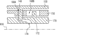
−安全リング(150)が第二の位置にあるときに、縦方向軸線を中心にしたかつ安全リングに対する操作リングの回転(F2,F4)の運動を、操作リング(130)に対する本体(102)の軸方向の並進運動(F3)に変換するための手段(170,158;130,179;170,158;170,147)を備えていることを特徴とするメス側継手要素。 - 運動を変換するための手段が、本体(102)周囲で、回転の際には可動に、かつ並進運動の際には一体的に取付られている駆動リング(170)を備えていること、操作リング(130)と駆動リング(170)の間のリングの一方(170)が、相対的軸方向運動ができることにより、操作リングと一緒に駆動リングを回転の際には固定するための少なくとも一つの部材(178;173)を備えていること、そして駆動リングと安全リング(150)の中のリング(170;150)の一方が、安全リング(150)に対して螺旋運動の際に駆動リング(170)を案内するための少なくとも一つの部材(178;174)を備えていることを特徴とする請求項1に記載のメス側要素。
- 運動を変換するための手段が、本体の周囲で、回転の際には可動に、かつ並進運動の際には一体的に取付られている駆動リング(170)を備えていること、安全リング(150)と駆動リング(170)の間のリング一方(170)が、相対運動ができることにより、安全リングと一緒に駆動リングを回転の際に固定するための少なくとも一つの部材(172;175)を備えていること、そして駆動リング(170)と操作リング(130)の中のリング(170;130)の一方が、操作リング(130)に対して螺旋運動の際に駆動リング(170)を案内するための少なくとも一つの部材(148;175)を備えていることを特徴とする請求項1に記載のメス側要素。
- 回転の際に固定するための部材(178;173;175)と案内するための部材(178;174;175)が、駆動リングと一体であることを特徴とする請求項2または3に記載のメス側要素。
- 回転の際に固定するための部材と案内するための部材が、同じ部材(178;175)に組合されることを特徴とする請求項4に記載のメス側要素。
- 回転の際に固定するための部材と案内するための部材が、二つの独立した部材(148,172;173,174)であることを特徴とする請求項2または3に記載のメス側要素。
- 回転の際に固定するための部材(172)と案内するための部材(148)が、操作リング(130)、安全リング(150)及び駆動リング(170)の中の二つの独立したリング(130,170)と一体化されているかあるいは一体式であることを特徴とする請求項6に記載のメス側要素。
- 回転の際に固定するための部材がピン(178;172;173;175)であり、このピンがリングの内の一つ(170)と一体であり、かつ本体の縦方向軸線に対して平行な、少なくともリングの内の他方(130;150)の縦方向部分内で溝(138;168B;168D)内で係合しており、案内するための部材がピン(178;148;174;175)であり、このピンがリングの内の一つ(170;130)と一体であり、かつリングの内の他方(150;170;130)の溝(158;179;158;147)内で係合してことを特徴とする請求項2〜7のいずれか一つに記載のメス側要素。
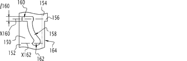
- 安全リングの第一の位置で、回転の際に固定しかつ案内するためのピン(178)が、螺旋溝(158)を拡張する切込み(160)内で係合しており、この切込みが本体の縦方向軸線に対して平行に(X160)延びていることを特徴とする請求項5〜8のいずれか一つに記載のメス側要素。
- メス側要素が第一の位置に向かって安全リング(150)を弾性的に戻すための手段(180)を備えていることを特徴とする請求項1〜9のいずれか一つに記載のメス側要素。
- 安全リング(150)がその第二の位置にある場合に(図3)、及び安全リングがその第一の位置にある場合に(図1)、操作リング(130)が安全リングに関して、その角度位置に対して縦方向軸線(X10)を中心に回転しない限り、安全リングの遠位端部(154)が本体(102)の正面(108)よりも外側へ突出していることを特徴とする請求項1〜10のいずれか一つに記載のメス側要素。
- 弁が逃がし弁(110)の閉鎖位置にあると、弁(110)が本体(102)の平坦な正面(108)と面一である平坦な正面(111)を備えていることを特徴とする請求項1〜11のいずれか一つに記載のメス側要素。
- 座部が本体(102)の内側のテーパの付いた面(18)により形成されており、このテーパの付いた面がメス側要素(10)の正面の方向で縦方向軸線(X10)に向かって収束していることを特徴とする請求項1〜12のいずれか一つに記載のメス側要素。
- 二つの流体導管(C1,C2)を接続するための迅速継手(2)において、迅速継手が、請求項1〜13のいずれか一つに記載のメス側要素(10)とこのメス側要素と補完的なオス側要素(20)を備えていることを特徴とする迅速継手。
- オス側要素が、
−第二の本体(202)であって、この第二の本体が、第二の縦方向軸線(X20)が中心に来るよう位置決めされ、かつ流体の流れのための第二の導管(221)を定義している第二の本体(202)と、
−第二の弁(210)を備えた第二の逃がし弁(220)であって、この逃がし弁が流体の通路のための導管内に収容されており、かつ第二の本体により形成された第二の逃がし弁の座部(218)に当接している第二の逃がし弁の閉鎖位置と座部から引離された第二の逃がし弁の開放位置の間で、第二の本体に対して第二の縦方向軸線に沿って可動である逃がし弁(120)とを備えていること、そして
−オス側およびメス側の要素の圧入(F1,F3)時におよび結合された配置において、第二の本体が、安全リング(150)を回転の際に固定するための少なくとも一つの起伏部(226,227)を備えていることを特徴とする請求項14に記載の迅速継手。 - 安全リング(150)がその第二の位置にある場合に(図3)、かつ安全リング(150)がその第一の位置にある場合に(図1)、操作リングが安全リングに関して、その角度位置に対して、メス側要素(10)の本体(102)の縦方向軸線(X10)を中心に回転しない限り、安全リングが、操作リングとオス側要素を一緒にまとめるための当接部を構成することを特徴とする請求項14または15に記載の迅速継手。
Applications Claiming Priority (2)
| Application Number | Priority Date | Filing Date | Title |
|---|---|---|---|
| FR1356290A FR3007817B1 (fr) | 2013-06-28 | 2013-06-28 | Element femelle de raccord rapide et raccord rapide comprenant un tel element |
| FR1356290 | 2013-06-28 |
Publications (2)
| Publication Number | Publication Date |
|---|---|
| JP2015028381A JP2015028381A (ja) | 2015-02-12 |
| JP6460656B2 true JP6460656B2 (ja) | 2019-01-30 |
Family
ID=49111446
Family Applications (1)
| Application Number | Title | Priority Date | Filing Date |
|---|---|---|---|
| JP2014127990A Active JP6460656B2 (ja) | 2013-06-28 | 2014-06-23 | メス側迅速継手要素及びこのような要素を備えた迅速継手 |
Country Status (6)
| Country | Link |
|---|---|
| US (1) | US9360142B2 (ja) |
| EP (1) | EP2818781B1 (ja) |
| JP (1) | JP6460656B2 (ja) |
| CN (1) | CN104251357B (ja) |
| FR (1) | FR3007817B1 (ja) |
| IN (1) | IN2014DE01683A (ja) |
Families Citing this family (23)
| Publication number | Priority date | Publication date | Assignee | Title |
|---|---|---|---|---|
| ITMI20150642A1 (it) | 2015-05-07 | 2016-11-07 | Alfa Gomma S P A | Innesto rapido femmina innestabile in pressione |
| CN105465519B (zh) * | 2015-08-25 | 2018-04-24 | 中航光电科技股份有限公司 | 一种插头连接器及使用该插头连接器的流体连接器组件 |
| FR3048822B1 (fr) * | 2016-03-11 | 2018-04-06 | Staubli Faverges | Raccord electrique |
| CN108569413B (zh) * | 2017-03-09 | 2024-08-06 | 昆山合朗航空科技有限公司 | 快拆结构及云台 |
| FR3069612B1 (fr) * | 2017-07-25 | 2019-09-06 | Staubli Faverges | Element de raccord pour connecter une conduite de fluide |
| FR3071278B1 (fr) * | 2017-09-18 | 2020-02-21 | Sogefi Air & Cooling | Dispositif de pompe a debit variable et circuit comprenant une telle pompe |
| SE541351C2 (en) * | 2017-12-07 | 2019-08-13 | Scania Cv Ab | An indoor safety device, a liquefied fuel gas system and a vehicle |
| JP7066121B2 (ja) * | 2018-05-18 | 2022-05-13 | ペット エンジニアリング アンド サーヴィシーズ エスアールエル | 液体燃料燃焼器及び液体燃料燃焼器用の連結構造 |
| CN110500463B (zh) * | 2019-07-17 | 2021-08-20 | 华为技术有限公司 | 一种接头、冷却系统和计算机装置 |
| FR3101389B1 (fr) * | 2019-09-30 | 2021-10-22 | Staubli Sa Ets | Raccord fluidique |
| JP7458019B2 (ja) * | 2019-12-25 | 2024-03-29 | 株式会社コスメック | 開閉弁装置 |
| DE102020110477A1 (de) * | 2020-04-17 | 2021-10-21 | Schaeffler Technologies AG & Co. KG | Vorrichtung und Verfahren zum Anschluss einer Kühldüse an eine Kühlschmiermittelzuführung |
| CN115702306A (zh) * | 2020-08-27 | 2023-02-14 | 考尔得产品公司 | 流体联接器 |
| CN112635952B (zh) * | 2020-12-25 | 2023-01-06 | 北京华航无线电测量研究所 | 一种液冷相控阵天线及其冷却方法 |
| CN112728258B (zh) * | 2020-12-25 | 2023-02-03 | 北京华航无线电测量研究所 | 一种进出液接头及其连通方法 |
| CN113464747B (zh) * | 2021-06-26 | 2025-03-14 | 邱强生 | 一种阀门快速接头 |
| CN113566040B (zh) * | 2021-08-02 | 2025-12-12 | 瑞肯耐特流体控制系统(镇江)有限公司 | 连接器组件 |
| US12404962B2 (en) | 2021-08-02 | 2025-09-02 | A. Raymond Et Cie | Connector assembly |
| WO2023043437A1 (en) * | 2021-09-15 | 2023-03-23 | Aerojet Rocketdyne, Inc. | Dynamic quick connector coupling |
| FR3128001B1 (fr) | 2021-10-13 | 2023-10-27 | Staubli Sa Ets | Raccord rapide et ensemble de connexion comprenant un tel raccord rapide |
| JP2023070436A (ja) * | 2021-11-09 | 2023-05-19 | パナソニックIpマネジメント株式会社 | チューブ管用継手 |
| CN116734065B (zh) * | 2022-03-04 | 2025-09-30 | 宁波杜凯软管有限公司 | 自锁快速接头及其自锁和解锁方法 |
| WO2023229704A1 (en) * | 2022-05-23 | 2023-11-30 | Colder Products Company | Aseptic fluid couplings |
Family Cites Families (9)
| Publication number | Priority date | Publication date | Assignee | Title |
|---|---|---|---|---|
| GB691568A (en) * | 1951-03-12 | 1953-05-13 | Avery Hardoll Ltd | Improvements in or relating to coupling devices for pipes or conduits |
| JPH0616205Y2 (ja) * | 1988-12-28 | 1994-04-27 | 日東工器株式会社 | 管継手用ソケットとプラグ並びにこれらを用いる配管接続システム |
| US5009252A (en) * | 1990-05-03 | 1991-04-23 | The United States Of America As Represented By The Secretary Of The Army | Air distribution connector valve |
| SE507753C2 (sv) * | 1996-11-18 | 1998-07-13 | Todo Produktions & Foersaeljni | Slangkopplingsdel |
| FR2810388B1 (fr) * | 2000-06-15 | 2002-08-09 | Staubli Sa Ets | Raccord a rampe de verrouillage |
| FR2889728B1 (fr) * | 2005-08-10 | 2007-10-05 | Staubli Faverges Sca | Ensemble de raccord pour circuit fluidique |
| FR2901595A1 (fr) * | 2006-05-29 | 2007-11-30 | Staubli Faverges Sca | Element de raccord a rainure de verrouillage et raccord incorporant un tel element |
| SE531081C2 (sv) * | 2007-04-18 | 2008-12-09 | Nyberg Bo Erik | Koaxial koppling |
| FR2984990B1 (fr) * | 2011-12-23 | 2014-02-28 | Staubli Sa Ets | Raccord destine a realiser la jonction amovible de deux canalisations de fluide |
-
2013
- 2013-06-28 FR FR1356290A patent/FR3007817B1/fr active Active
-
2014
- 2014-06-18 US US14/308,466 patent/US9360142B2/en not_active Expired - Fee Related
- 2014-06-23 JP JP2014127990A patent/JP6460656B2/ja active Active
- 2014-06-24 IN IN1683DE2014 patent/IN2014DE01683A/en unknown
- 2014-06-27 EP EP14174688.3A patent/EP2818781B1/fr active Active
- 2014-06-30 CN CN201410307099.XA patent/CN104251357B/zh active Active
Also Published As
| Publication number | Publication date |
|---|---|
| US20150001844A1 (en) | 2015-01-01 |
| FR3007817A1 (fr) | 2015-01-02 |
| IN2014DE01683A (ja) | 2015-06-19 |
| EP2818781A1 (fr) | 2014-12-31 |
| EP2818781B1 (fr) | 2016-09-07 |
| JP2015028381A (ja) | 2015-02-12 |
| CN104251357B (zh) | 2018-08-31 |
| CN104251357A (zh) | 2014-12-31 |
| FR3007817B1 (fr) | 2015-07-17 |
| US9360142B2 (en) | 2016-06-07 |
Similar Documents
| Publication | Publication Date | Title |
|---|---|---|
| JP6460656B2 (ja) | メス側迅速継手要素及びこのような要素を備えた迅速継手 | |
| US7766393B2 (en) | Female coupling element and a coupling including such an element | |
| EP3286475B1 (en) | Single-use aseptic fluid couplings | |
| JPH09511047A (ja) | 深紋り急速連結継手 | |
| US8720487B2 (en) | Grease delivery receiver and nozzle couplable without fluid pressure bleed-down and having pressurization lockout and flush face coupling | |
| CN103174894A (zh) | 用于可拆卸连接两个流体通道的连接器 | |
| JP2014178029A (ja) | 二つの液体管路の取り外し可能な接続形態を構成するための雌部品及び継手 | |
| CN107013776B (zh) | 快插接头的插槽件与包括此插槽件的快插接头 | |
| JP2004169919A (ja) | 2本のパイプを分離可能に連結する急速連結器 | |
| KR102229523B1 (ko) | 독립 부재 압력 완화 캠을 구비한 유체 전달 커플링 | |
| JP2019530839A (ja) | 継手および継手アセンブリならびに継手を製造する方法 | |
| JP2017500519A (ja) | 正面環状シールを有する流体搬送平坦面カプラー | |
| CN104428573B (zh) | 具有安装应力减小环的流体连通装置 | |
| CN115681650A (zh) | 阳型流体连接元件和包括这种阳型元件的流体连接器 | |
| US7028982B2 (en) | Coupling member for a pipe coupling | |
| EP4381216B1 (en) | Connector assembly | |
| RU2402713C2 (ru) | Соединительный узел для трубопроводов | |
| TW202104781A (zh) | 閥構造體、接頭構件及管接頭 | |
| CN104520614A (zh) | 用于变速器、尤其是用于机动车变速器的止动装置 | |
| CN114174710B (zh) | 流体连接器的插入式构件、具有这种插入式构件的流体连接器以及这种插入式构件的装配方法 | |
| US9534699B2 (en) | Lower effort quick-connect coupler | |
| MX2009001316A (es) | Acoplamiento macho para conectarse a un acoplamiento hembra roscado. | |
| CN208138665U (zh) | 流体联接器 | |
| JP7402710B2 (ja) | 管継手部材および管継手 | |
| JP7833048B2 (ja) | 管継手部材 |
Legal Events
| Date | Code | Title | Description |
|---|---|---|---|
| A621 | Written request for application examination |
Free format text: JAPANESE INTERMEDIATE CODE: A621 Effective date: 20170523 |
|
| A131 | Notification of reasons for refusal |
Free format text: JAPANESE INTERMEDIATE CODE: A131 Effective date: 20180322 |
|
| A977 | Report on retrieval |
Free format text: JAPANESE INTERMEDIATE CODE: A971007 Effective date: 20180323 |
|
| A521 | Request for written amendment filed |
Free format text: JAPANESE INTERMEDIATE CODE: A523 Effective date: 20180614 |
|
| TRDD | Decision of grant or rejection written | ||
| A01 | Written decision to grant a patent or to grant a registration (utility model) |
Free format text: JAPANESE INTERMEDIATE CODE: A01 Effective date: 20181205 |
|
| A61 | First payment of annual fees (during grant procedure) |
Free format text: JAPANESE INTERMEDIATE CODE: A61 Effective date: 20181225 |
|
| R150 | Certificate of patent or registration of utility model |
Ref document number: 6460656 Country of ref document: JP Free format text: JAPANESE INTERMEDIATE CODE: R150 |
|
| R250 | Receipt of annual fees |
Free format text: JAPANESE INTERMEDIATE CODE: R250 |
|
| R250 | Receipt of annual fees |
Free format text: JAPANESE INTERMEDIATE CODE: R250 |
|
| R250 | Receipt of annual fees |
Free format text: JAPANESE INTERMEDIATE CODE: R250 |
|
| R250 | Receipt of annual fees |
Free format text: JAPANESE INTERMEDIATE CODE: R250 |
|
| R250 | Receipt of annual fees |
Free format text: JAPANESE INTERMEDIATE CODE: R250 |