JP6440017B2 - Developing device and image forming apparatus - Google Patents

Developing device and image forming apparatus Download PDF

Info

Publication number
JP6440017B2
JP6440017B2 JP2014194048A JP2014194048A JP6440017B2 JP 6440017 B2 JP6440017 B2 JP 6440017B2 JP 2014194048 A JP2014194048 A JP 2014194048A JP 2014194048 A JP2014194048 A JP 2014194048A JP 6440017 B2 JP6440017 B2 JP 6440017B2
Authority
JP
Japan
Prior art keywords
developer
developing device
discharge
closing member
opening
Prior art date
Legal status (The legal status is an assumption and is not a legal conclusion. Google has not performed a legal analysis and makes no representation as to the accuracy of the status listed.)
Active
Application number
JP2014194048A
Other languages
Japanese (ja)
Other versions
JP2016065952A (en
JP2016065952A5 (en
Inventor
高橋 裕
裕 高橋
慧之輔 近藤
慧之輔 近藤
健太郎 三國谷
健太郎 三國谷
小池 寿男
寿男 小池
小杉 秀樹
秀樹 小杉
彰 藤森
彰 藤森
晃弘 川上
晃弘 川上
高見 伸雄
伸雄 高見
吉田 圭一
圭一 吉田
Current Assignee (The listed assignees may be inaccurate. Google has not performed a legal analysis and makes no representation or warranty as to the accuracy of the list.)
Ricoh Co Ltd
Original Assignee
Ricoh Co Ltd
Priority date (The priority date is an assumption and is not a legal conclusion. Google has not performed a legal analysis and makes no representation as to the accuracy of the date listed.)
Filing date
Publication date
Application filed by Ricoh Co Ltd filed Critical Ricoh Co Ltd
Priority to JP2014194048A priority Critical patent/JP6440017B2/en
Publication of JP2016065952A publication Critical patent/JP2016065952A/en
Publication of JP2016065952A5 publication Critical patent/JP2016065952A5/ja
Application granted granted Critical
Publication of JP6440017B2 publication Critical patent/JP6440017B2/en
Active legal-status Critical Current
Anticipated expiration legal-status Critical

Links

Images

Description

本発明は、複写機、ファクシミリ、プリンタ等に用いられる現像装置及びにこれを備えた画像形成装置に関するものである。   The present invention relates to a developing device used for a copying machine, a facsimile, a printer, and the like, and an image forming apparatus provided with the developing device.

従来から、トナーと磁性キャリアとを含む二成分の現像剤を用いた現像装置を備える画像形成装置が広く用いられている。この種の画像形成装置として、現像に伴ってトナーを消費する現像装置内の現像剤に対して、必要に応じてトナー収容器からトナーを補給することで、現像剤のトナー濃度を所定範囲内に維持するものがある。かかる構成では、現像剤内のキャリアは殆ど消費されず繰り返し使用されるため、画像を出力するにしたがってキャリアの表層のコート層が磨耗したり逆にコート層にトナー樹脂や添加剤が付着したりする。これにより、キャリアのトナーを帯電させる能力が徐々に低下して、キャリアが劣化した状態となる。   Conventionally, an image forming apparatus including a developing device using a two-component developer including toner and a magnetic carrier has been widely used. As an image forming apparatus of this type, the toner density of the developer is kept within a predetermined range by supplying toner from the toner container as necessary to the developer in the developing apparatus that consumes toner with development. There is something to keep in. In such a configuration, the carrier in the developer is hardly consumed and is repeatedly used. As the image is output, the coat layer on the surface of the carrier wears out, and conversely, toner resin and additives adhere to the coat layer. To do. As a result, the ability of the carrier to charge the toner gradually decreases, and the carrier is in a deteriorated state.

キャリアの劣化が進行するとトナーの帯電量が低下し、地肌部汚れやトナー飛散等を引き起こすため、この種の画像形成装置では定期的にサービスマンがユーザーを訪問してキャリアの交換を行っていた。このために、メンテナンス費用がかかり画像形成の単価が高くなってしまっていた。   As the deterioration of the carrier progresses, the charge amount of the toner decreases, causing stains on the background and toner scattering, etc. In this type of image forming apparatus, a service person visits the user regularly to replace the carrier. . For this reason, maintenance costs are incurred, and the unit price for image formation is high.

特許文献1や特許文献2には、キャリアとトナーとを混合したプレミックス現像剤を現像装置内の現像剤に補給してトナー濃度の回復を図りながら、増加量分の現像剤を現像装置から排出させる現像装置が記載されている。かかる構成では、現像剤の排出によって古くなったキャリアを少しずつ現像装置内から排出しつつ、プレミックス現像剤中の新しいキャリアを現像装置内の現像剤に補給する。そして、このような排出と補給とによって現像剤中のキャリアを少しずつ新たなものに交換していくことで、キャリアの交換作業を省くことができる。
また、特許文献1及び特許文献2の現像装置では、装置内の現像剤量の増減に応じて現像剤を装置外に排出する現像剤排出口を備えている。これらの現像装置では、プレミックス現像剤が補給され、現像装置内の現像剤量が増加すると、供給搬送路内の現像剤の嵩が高くなる。このとき、現像剤排出口を設けた位置で、現像剤排出口の高さまで到達した現像剤は現像剤排出口から現像装置外部へ排出される。
In Patent Documents 1 and 2, a premix developer in which a carrier and a toner are mixed is replenished to the developer in the developing device to restore the toner density, and an increased amount of developer is removed from the developing device. A developing device to be discharged is described. In such a configuration, a new carrier in the premix developer is replenished to the developer in the developing device while the carrier that has become old due to the discharge of the developer is gradually discharged from the developing device. Then, the carrier replacement work can be omitted by replacing the carrier in the developer gradually with a new one by such discharge and replenishment.
Further, the developing devices of Patent Literature 1 and Patent Literature 2 are provided with a developer discharge port for discharging the developer to the outside of the device in accordance with the increase or decrease in the amount of developer in the device. In these developing devices, when the premix developer is replenished and the amount of developer in the developing device increases, the bulk of the developer in the supply conveyance path increases. At this time, the developer reaching the height of the developer discharge port at the position where the developer discharge port is provided is discharged from the developer discharge port to the outside of the developing device.

さらに、特許文献2に記載の現像装置は、供給搬送路内の現像剤が現像剤排出口に向かう排出経路を閉鎖する閉鎖状態と、排出経路を開放する開放状態とを選択的に取り得る排出経路開閉部材を備える。この現像装置では、現像剤の剤面が現像剤排出口よりも低い状態では、排出経路開閉部材が剤面上方を覆うことによって、現像剤搬送スクリュの回転によって飛翔した現像剤が現像剤排出口に向かう経路を塞ぐ。現像剤の剤面が現像剤排出口よりも高くなった場合には、排出経路開閉部材が現像剤によって押し上げられることによって開く。この状態では現像剤を現像剤排出口を通して排出する。
特許文献2には、現像剤の剤面の高さによって現像剤排出口へ向かう経路の開閉を行うことで、飛び跳ねた現像剤が排出されることを防止し、現像装置内の現像剤量が増加していないにもかかわらず現像剤が排出されることを防止できることが記載されている。
Furthermore, the developing device described in Patent Document 2 is a discharge that can selectively take a closed state in which the developer in the supply conveyance path closes the discharge path toward the developer discharge port and an open state in which the discharge path is opened. A path opening / closing member is provided. In this developing apparatus, in a state where the developer surface is lower than the developer discharge port, the discharge path opening / closing member covers the upper surface of the developer, so that the developer flying by the rotation of the developer conveying screw is discharged to the developer discharge port. Block the path to the. When the developer surface becomes higher than the developer discharge port, the discharge path opening / closing member is opened by being pushed up by the developer. In this state, the developer is discharged through the developer discharge port.
In Patent Document 2, the path toward the developer discharge port is opened and closed depending on the height of the developer surface, thereby preventing the jumped developer from being discharged, and the amount of developer in the developing device is reduced. It is described that it is possible to prevent the developer from being discharged even though it has not increased.

しかしながら、特許文献2に記載の現像装置は板状の排出経路開閉部材の一端を中心に他端が揺動することで開閉する構成であり、排出経路開閉部材の他端の先端面が現像剤排出口の下方の壁面に接触または近接対向することで閉鎖状態となる。このような現像装置では、排出経路開閉部材の揺動中心となる一端の取り付け位置が組み付け誤差によって現像剤排出口側に寄り過ぎてしまうと、閉鎖状態のときに他端が壁面に突き当たってしまい、円滑な開閉動作を行えなくなる。また、上記一端の取り付け位置が現像剤排出口から離れる側に寄り過ぎてしまうと、閉鎖状態であっても他端と壁面との間に現像剤が通過可能な隙間が出来てしまい、余計な現像剤の排出を防止することができない。このため、排出経路開閉部材を高い組み付け精度で組み付けることが求められる。   However, the developing device described in Patent Document 2 has a configuration in which the other end of the discharge path opening / closing member swings around one end of the plate-like discharge path opening / closing member, and the tip end surface of the other end of the discharge path opening / closing member is the developer. It will be in a closed state by contacting or approaching the wall surface below the discharge port. In such a developing device, if the attachment position of one end, which is the swing center of the discharge path opening / closing member, is too close to the developer discharge port side due to an assembly error, the other end abuts against the wall surface in the closed state. Smooth opening / closing operation cannot be performed. In addition, if the attachment position of the one end is too close to the side away from the developer discharge port, a gap through which the developer can pass is created between the other end and the wall surface even in the closed state. The developer cannot be prevented from being discharged. For this reason, it is required to assemble the discharge path opening / closing member with high assembling accuracy.

本発明は以上の問題点に鑑みなされたものであり、その目的は、次の通りである。すなわち、装置内の現像剤量が増加していないにもかかわらず現像剤が排出されることを抑制するための排出経路開閉部材の組み付け精度を従来よりも低くできる現像装置、及び、その現像装置を備えた画像形成装置を提供することである。   The present invention has been made in view of the above problems, and the object thereof is as follows. That is, a developing device capable of lowering the assembly accuracy of the discharge path opening / closing member for suppressing discharge of the developer even though the amount of developer in the device is not increased, and the developing device Is provided.

上記目的を達成するために、請求項1の発明は、現像剤を表面上に担持する現像剤担持体と、前記現像剤担持体に供給する現像剤を収容する現像剤収容部内の現像剤を搬送する現像剤搬送部材と、を有し、前記現像剤収容部を形成する収容部形成壁の所定の高さに、現像剤を装置外部に排出する現像剤排出口を設け、前記現像剤収容部内から前記現像剤排出口に向かう現像剤が通過する排出経路を閉鎖する閉鎖状態と、前記排出経路を開放する開放状態とを選択的に取り得る排出経路開閉部材を備え、前記排出経路開閉部材は、一端を中心に他端が揺動可能で、閉鎖状態から他端側が持ち上がることで開放状態となる現像装置において、閉鎖状態では前記排出経路開閉部材の他端側が前記現像剤排出口に入り込み、前記排出経路開閉部材の下面が前記収容部形成壁における前記現像剤排出口の下端部分に接触し、前記排出経路を挟んで前記現像剤排出口と対向する位置に排出口対向部材を備え、前記排出経路開閉部材の一端側の上面を前記排出口対向部材の下面に貼り付けることで、前記排出経路開閉部材の一端を固定することを特徴とするものである。 To achieve the above object, a first aspect of the invention, a developer carrying member for carrying a developer on the surface, the developer in the developer accommodating portion for accommodating a developer to be supplied to said developer carrying member anda developer carrying member for conveying, at a predetermined height of the housing portion forming the wall that forms the developer accommodating portion, provided a developer discharge port for discharging the developer to the outside of the apparatus, the developer containing comprising a closed state to close the discharge path which the developer passes from portion toward the developer discharge port, the discharge passage controlling member that can be taken selectively an open state to open the discharge path, the discharge passage controlling member has one center to the other end is pivotable and in the developing device in an open state by the other end is lifted from the closed state, the other end of the discharge passage controlling member enters the developer discharge opening in a closed condition under the discharge passage controlling member There contacts the lower end portion of the developer discharge opening in the housing section forming wall, a discharge opening opposing member at a position opposed to the developer discharge port across the discharge path, one end of the discharge passage controlling member Is attached to the lower surface of the discharge port facing member to fix one end of the discharge path opening / closing member .

本発明によれば、装置内の現像剤量が増加していないにもかかわらず現像剤が排出されることを抑制するための排出経路開閉部材の組み付け精度を従来よりも低くできる、という優れた効果がある。   According to the present invention, the assembly accuracy of the discharge path opening / closing member for suppressing the discharge of the developer even though the amount of the developer in the apparatus is not increased can be made lower than before. effective.

実施例1の現像装置の閉鎖状態の断面説明図。FIG. 3 is a cross-sectional explanatory diagram of the developing device according to the first embodiment in a closed state. 本実施形態に係る複写機の概略構成図。1 is a schematic configuration diagram of a copier according to an embodiment. 現像装置及び感光体の概略構成図。FIG. 2 is a schematic configuration diagram of a developing device and a photoreceptor. 現像剤の流れを説明する現像装置の斜視断面図。FIG. 3 is a perspective cross-sectional view of the developing device for explaining the flow of the developer. 現像装置内の現像剤の流れの模式図。FIG. 3 is a schematic diagram of a developer flow in a developing device. 現像装置の断面説明図。Cross-sectional explanatory drawing of a developing device. 図5とは異なる形状の現像装置内の現像剤の流れの模式図。FIG. 6 is a schematic diagram of a developer flow in a developing device having a shape different from that in FIG. 5. 現像装置の外観斜視図。FIG. 実施例1の現像装置の開放状態の断面説明図。FIG. 3 is an explanatory cross-sectional view of the developing device according to the first embodiment in an open state. 実施例1の現像装置を図1中の手前側の斜め上方から見た斜視断面図。FIG. 2 is a perspective cross-sectional view of the developing device according to the first exemplary embodiment when viewed from an obliquely upper side on the near side in FIG. 1. 図10に示す状態から排出経路開閉部材を取り外した状態の実施例1の現像装置の斜視断面図。FIG. 11 is a perspective cross-sectional view of the developing device of Example 1 in a state where a discharge path opening / closing member is removed from the state shown in FIG. 10. 実施例1の現像装置を図1中の奥側の斜め上方から見た斜視断面図。FIG. 2 is a perspective cross-sectional view of the developing device according to the first exemplary embodiment when viewed obliquely from the back side in FIG. 図12に示す状態から排出経路開閉部材を取り外した状態の実施例1の現像装置の斜視断面図。FIG. 13 is a perspective cross-sectional view of the developing device of Example 1 in a state where the discharge path opening / closing member is removed from the state shown in FIG. 12. 実施例1の現像装置を図1中の奥側の斜め下方から見た斜視断面図。FIG. 2 is a perspective cross-sectional view of the developing device according to the first exemplary embodiment when viewed from the diagonally lower side in FIG. 図14に示す状態から排出経路開閉部材を取り外した状態の実施例1の現像装置の斜視断面図。FIG. 15 is a perspective cross-sectional view of the developing device of Example 1 in a state where the discharge path opening / closing member is removed from the state shown in FIG. 14. 実施例1の現像装置の供給搬送路の下流端近傍の拡大説明図。FIG. 3 is an enlarged explanatory view in the vicinity of a downstream end of a supply conveyance path of the developing device of Embodiment 1. 実施例2の現像装置の閉鎖状態の断面説明図。FIG. 10 is a cross-sectional explanatory diagram of the developing device according to the second embodiment in a closed state. 実施例3の現像装置の閉鎖状態の断面説明図。FIG. 10 is a cross-sectional explanatory diagram of the developing device according to the third embodiment in a closed state. 現像剤排出口を備えた従来の現像装置の断面説明図。Sectional explanatory drawing of the conventional image development apparatus provided with the developer discharge port. 特許文献2に記載の現像装置の概略を説明する供給搬送路近傍の拡大断面図。FIG. 6 is an enlarged cross-sectional view in the vicinity of a supply conveyance path for explaining an outline of a developing device described in Patent Document 2;

以下、図面を参照して本発明の実施形態について説明する。
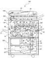
図2は、本発明を適用可能な画像形成装置であり、複数の感光体が並行配設されたタンデム型のカラーレーザー複写機(以下、「複写機500」という)の概略構成図である。複写機500はプリンタ部100、これを載せる給紙装置200、プリンタ部100の上に固定されたスキャナ300等を備えている。また、このスキャナ300の上に固定された原稿自動搬送装置400等も備えている。
Hereinafter, embodiments of the present invention will be described with reference to the drawings.
FIG. 2 is an image forming apparatus to which the present invention can be applied, and is a schematic configuration diagram of a tandem type color laser copying machine (hereinafter referred to as “copying machine 500”) in which a plurality of photoconductors are arranged in parallel. The copier 500 includes a printer unit 100, a paper feeding device 200 on which the printer unit 100 is placed, a scanner 300 fixed on the printer unit 100, and the like. An automatic document feeder 400 fixed on the scanner 300 is also provided.

プリンタ部100は、イエロー(Y)、マゼンダ(M)、シアン(C)、黒(K)の各色の画像を形成するための四つの画像形成ユニット20(Y,M,C,K)を備えている。各符号の数字の後に付されたY,M,C,Kは、イエロー、シアン、マゼンダ、ブラック用の部材であることを示している(以下同様)。画像形成ユニット20(Y,M,C,K)の他には、光書込ユニット21、中間転写ユニット17、二次転写装置22、レジストローラ対49、ベルト定着方式の定着装置25等が配設されている。   The printer unit 100 includes four image forming units 20 (Y, M, C, K) for forming images of each color of yellow (Y), magenta (M), cyan (C), and black (K). ing. Y, M, C, and K attached to the numbers of the respective symbols indicate members for yellow, cyan, magenta, and black (the same applies hereinafter). In addition to the image forming unit 20 (Y, M, C, K), an optical writing unit 21, an intermediate transfer unit 17, a secondary transfer device 22, a registration roller pair 49, a belt fixing type fixing device 25, and the like are arranged. It is installed.

光書込ユニット21は、図示しない光源、ポリゴンミラー、f−θレンズ、反射ミラー等を有し、画像データに基づいて四つの感光体1(Y,M,C,K)の表面にレーザー光を照射する。   The optical writing unit 21 includes a light source, a polygon mirror, an f-θ lens, a reflection mirror, and the like (not shown), and laser light is applied to the surfaces of the four photosensitive members 1 (Y, M, C, K) based on image data. Irradiate.

画像形成ユニット20(Y,M,C,K)は、それぞれドラム状の感光体1(Y,M,C,K)と、その周囲に配置された帯電装置、現像装置4(Y,M,C,K)、ドラムクリーニング装置、除電器等を一つのユニットとして、共通の支持体に支持している。画像形成ユニット20(Y,M,C,K)は、一つのユニットとして共通の支持体に支持してプロセスカートリッジを構成し、四つのプロセスカートリッジのそれぞれが複写機500本体に対して着脱可能になっている。本実施形態の複写機500は、プロセスカートリッジである四つの画像形成ユニット20(Y,M,C,K)をプリンタ部100に並べて配置する構成である。プロセスカートリッジとすることで、画像形成ユニット20の交換性が向上する。   The image forming unit 20 (Y, M, C, K) includes a drum-shaped photoreceptor 1 (Y, M, C, K), a charging device and a developing device 4 (Y, M, C, K), a drum cleaning device, a static eliminator, etc. are supported as a unit on a common support. The image forming unit 20 (Y, M, C, K) is supported on a common support as one unit to form a process cartridge, and each of the four process cartridges can be attached to and detached from the copying machine 500 main body. It has become. The copying machine 500 according to the present embodiment has a configuration in which four image forming units 20 (Y, M, C, K), which are process cartridges, are arranged side by side on the printer unit 100. By using the process cartridge, the exchangeability of the image forming unit 20 is improved.

四つの画像形成ユニット20(Y,M,C,K)は、それぞれが扱うトナーの色が異なる点の他がほぼ同様の構成になっているので、以下、使用するトナーの色を示す「Y」、「M」、「C」、「K」という添字は適宜省略する。
帯電手段たる帯電器によって、感光体1の表面は一様帯電される。帯電処理が施された感光体1の表面には、光書込ユニット21によって変調及び偏向されたレーザー光が照射される。すると、照射部(露光部)の電位が減衰する。この減衰により、感光体1表面に静電潜像が形成される。形成された静電潜像は現像手段たる現像装置4によって現像されてトナー像となる。
感光体1上に形成されたトナー像は、後述の中間転写ベルト110に一次転写される。一次転写後の感光体1の表面は、ドラムクリーニング装置によって転写残トナーがクリーニングされる。
The four image forming units 20 (Y, M, C, and K) have substantially the same configuration except that the colors of the toners handled by the four image forming units 20 (Y, M, C, and K) are different from each other. ”,“ M ”,“ C ”, and“ K ”are appropriately omitted.
The surface of the photoreceptor 1 is uniformly charged by a charger as a charging means. The surface of the photoreceptor 1 subjected to the charging process is irradiated with laser light modulated and deflected by the optical writing unit 21. Then, the potential of the irradiation part (exposure part) is attenuated. By this attenuation, an electrostatic latent image is formed on the surface of the photoreceptor 1. The formed electrostatic latent image is developed by the developing device 4 as developing means to become a toner image.
The toner image formed on the photoreceptor 1 is primarily transferred to an intermediate transfer belt 110 described later. The surface of the photosensitive member 1 after the primary transfer is cleaned of residual transfer toner by a drum cleaning device.

画像形成ユニット20において、ドラムクリーニング装置によってクリーニングされた感光体1は、除電器によって除電される。そして、帯電器によって一様帯電せしめられて、初期状態に戻る。以上のような一連のプロセスは、四つの画像形成ユニット20について同様に実行される。   In the image forming unit 20, the photoconductor 1 cleaned by the drum cleaning device is discharged by a charge eliminator. Then, it is uniformly charged by the charger and returns to the initial state. The series of processes as described above are similarly executed for the four image forming units 20.

次に、中間転写ユニットについて説明する。
中間転写ユニット17は、中間転写ベルト110やベルトクリーニング装置90等を有している。また、張架ローラ14、駆動ローラ15、二次転写バックアップローラ16、四つの一次転写バイアスローラ62(Y,M,C,K)等も有している。中間転写ベルト110は、張架ローラ14を含む複数のローラによってテンションを掛けられた状態で張架されている。そして、図示しないベルト駆動モータによって駆動される駆動ローラ15の回転によって図2中の時計回り方向に無端移動する。
Next, the intermediate transfer unit will be described.
The intermediate transfer unit 17 includes an intermediate transfer belt 110, a belt cleaning device 90, and the like. Further, it also includes a tension roller 14, a driving roller 15, a secondary transfer backup roller 16, four primary transfer bias rollers 62 (Y, M, C, K), and the like. The intermediate transfer belt 110 is stretched while being tensioned by a plurality of rollers including the stretching roller 14. Then, it moves endlessly in the clockwise direction in FIG. 2 by the rotation of the drive roller 15 driven by a belt drive motor (not shown).

四つの一次転写バイアスローラ62(Y,M,C,K)は、それぞれ中間転写ベルト110の内周面側に接触するように配設され、図示しない電源から一次転写バイアスの印加を受ける。また、四つの一次転写バイアスローラ62(Y,M,C,K)は、中間転写ベルト110をその内周面側から四つの感光体1(Y,M,C,K)に向けて押圧し、それぞれ一次転写ニップを形成する。各一次転写ニップには、一次転写バイアスの影響により、感光体1(Y,M,C,K)と一次転写バイアスローラ62(Y,M,C,K)との間に一次転写電界が形成される。   The four primary transfer bias rollers 62 (Y, M, C, K) are disposed so as to be in contact with the inner peripheral surface side of the intermediate transfer belt 110, respectively, and receive primary transfer bias from a power source (not shown). The four primary transfer bias rollers 62 (Y, M, C, K) press the intermediate transfer belt 110 from the inner peripheral surface side toward the four photosensitive members 1 (Y, M, C, K). Each forms a primary transfer nip. In each primary transfer nip, a primary transfer electric field is formed between the photoreceptor 1 (Y, M, C, K) and the primary transfer bias roller 62 (Y, M, C, K) due to the influence of the primary transfer bias. Is done.

イエロー用感光体1Y上に形成された上述のYトナー像は、この一次転写電界やニップ圧の影響によって中間転写ベルト110上に一次転写される。このYトナー像の上には、M,C,K用の感光体1(M,C,K)上に形成されたM,C,Kトナー像が順次重ね合わせて一次転写される。この重ね合わせの一次転写により、中間転写ベルト110上には四色のトナー像が重ね合わせられたトナー像(以下、四色トナー像という)が形成される。中間転写ベルト110上に重ね合わせ転写された四色トナー像は、後述の二次転写ニップで図示しない記録媒体たる転写紙に二次転写される。二次転写ニップ通過後の中間転写ベルト110の表面に残留する転写残トナーは、図2中左側の駆動ローラ15との間に中間転写ベルト110を挟み込むベルトクリーニング装置90によってクリーニングされる。   The above-described Y toner image formed on the yellow photoreceptor 1Y is primarily transferred onto the intermediate transfer belt 110 due to the influence of the primary transfer electric field and nip pressure. On the Y toner image, the M, C, and K toner images formed on the M, C, and K photoconductors 1 (M, C, and K) are sequentially superimposed and primarily transferred. By this superimposing primary transfer, a toner image (hereinafter, referred to as a four-color toner image) in which the four-color toner images are superimposed is formed on the intermediate transfer belt 110. The four-color toner image superimposed and transferred on the intermediate transfer belt 110 is secondarily transferred onto a transfer sheet (not shown) as a recording medium at a secondary transfer nip described later. Transfer residual toner remaining on the surface of the intermediate transfer belt 110 after passing through the secondary transfer nip is cleaned by a belt cleaning device 90 that sandwiches the intermediate transfer belt 110 with the driving roller 15 on the left side in FIG.

次に、二次転写装置22について説明する。
中間転写ユニット17の図中下方には、二本の紙搬送張架ローラ23によって紙搬送ベルト24を張架している二次転写装置22が配設されている。紙搬送ベルト24は、少なくとも何れか一方の紙搬送張架ローラ23の回転駆動に伴って、図2中の反時計回り方向に無端移動する。二本の紙搬送張架ローラ23のうち、図2中の右側に配設された一方の紙搬送張架ローラ23は、中間転写ユニット17の二次転写バックアップローラ16との間に、中間転写ベルト110及び紙搬送ベルト24を挟み込んでいる。この挟み込みにより、中間転写ユニット17の中間転写ベルト110と、二次転写装置22の紙搬送ベルト24とが接触する二次転写ニップが形成されている。
Next, the secondary transfer device 22 will be described.
Below the intermediate transfer unit 17 in the figure, a secondary transfer device 22 is disposed in which a paper transport belt 24 is stretched by two paper transport stretch rollers 23. The paper transport belt 24 moves endlessly in the counterclockwise direction in FIG. 2 in accordance with the rotational drive of at least one of the paper transport stretch rollers 23. One of the two paper conveyance stretching rollers 23 disposed on the right side in FIG. 2 is intermediately transferred to the secondary transfer backup roller 16 of the intermediate transfer unit 17. The belt 110 and the paper transport belt 24 are sandwiched. By this sandwiching, a secondary transfer nip is formed in which the intermediate transfer belt 110 of the intermediate transfer unit 17 and the paper transport belt 24 of the secondary transfer device 22 are in contact with each other.

二次転写ニップを形成する紙搬送張架ローラ23には、トナーと逆極性の二次転写バイアスが図示しない電源によって印加される。この二次転写バイアスの印加により、二次転写ニップには中間転写ベルト110上の四色トナー像を二次転写バックアップローラ16側から二次転写ニップを形成する紙搬送張架ローラ23側に向けて静電移動させる二次転写電界が形成される。   A secondary transfer bias having a polarity opposite to that of the toner is applied to the paper conveyance stretching roller 23 forming the secondary transfer nip by a power source (not shown). By applying this secondary transfer bias, the four-color toner image on the intermediate transfer belt 110 is transferred from the secondary transfer backup roller 16 side to the paper conveying stretch roller 23 side forming the secondary transfer nip in the secondary transfer nip. Thus, a secondary transfer electric field for electrostatic movement is formed.

二次転写ニップでは、中間転写ベルト110上の四色トナー像に同期するように後述のレジストローラ対49によって送り込まれた転写紙に対して、二次転写電界やニップ圧の影響を受けた四色トナー像が二次転写される。二次転写手段としては、ローラ部材に二次転写バイアスを印加する二次転写方式に代えて、転写紙を非接触でチャージさせるチャージャを設ける方式としてもよい。   At the secondary transfer nip, the transfer paper fed by a later-described registration roller pair 49 so as to synchronize with the four-color toner image on the intermediate transfer belt 110 is affected by the secondary transfer electric field and the nip pressure. A color toner image is secondarily transferred. As the secondary transfer means, instead of the secondary transfer system in which the secondary transfer bias is applied to the roller member, a system for providing a charger for charging the transfer paper in a non-contact manner may be provided.

複写機500本体の下部に設けられた給紙装置200は、複数の給紙カセット44が鉛直方向に多段に配置されたペーパーバンク43を備える。各給紙カセット44内には、複数の転写紙を紙束の状態で複数枚重ねて収容されている。それぞれの給紙カセット44は、紙束の一番上の転写紙に給紙ローラ42を押し当てている。そして、給紙ローラ42が回転することにより、一番上の転写紙を給紙路46に向けて送り出す。   A paper feeding device 200 provided at the lower portion of the copying machine 500 includes a paper bank 43 in which a plurality of paper feeding cassettes 44 are arranged in multiple stages in the vertical direction. In each paper feed cassette 44, a plurality of transfer sheets are accommodated in a stack of sheets. Each paper feed cassette 44 presses the paper feed roller 42 against the uppermost transfer paper in the paper bundle. Then, when the paper feed roller 42 rotates, the uppermost transfer paper is sent out toward the paper feed path 46.

給紙カセット44から送り出された転写紙を受け入れる給紙路46には、複数の搬送ローラ対47が配置されており、給紙路46における転写紙の搬送方向下流側端部にはレジストローラ対49が設けられている。給紙路46では受け入れた転写紙を搬送ローラ対47によってレジストローラ対49に向けて搬送する。   A plurality of transport roller pairs 47 are arranged in the paper feed path 46 that receives the transfer paper delivered from the paper feed cassette 44, and a pair of registration rollers is provided at the downstream end of the paper feed path 46 in the transport direction of the transfer paper. 49 is provided. In the paper feed path 46, the received transfer paper is conveyed toward the registration roller pair 49 by the conveyance roller pair 47.

レジストローラ対49に向けて搬送された転写紙は、レジストローラ対49のローラ間に挟まれ、停止する。一方、中間転写ユニット17において、中間転写ベルト110上に形成された四色トナー像は、中間転写ベルト110の無端移動に伴って上述した二次転写ニップに進入する。レジストローラ対49は、ローラ間に挟み込んだ転写紙を二次転写ニップにて中間転写ベルト110上の四色トナー像に密着させ得るタイミングで送り出す。これにより、二次転写ニップでは、中間転写ベルト110上の四色トナー像が転写紙に密着する。そして、転写紙に密着した四色トナー像が転写紙上に二次転写され、白色の転写紙上でフルカラー画像となる。このようにしてフルカラー画像が形成された転写紙は、紙搬送ベルト24の無端移動に伴って二次転写ニップを出た後、紙搬送ベルト24上から定着装置25に受け渡される。   The transfer sheet conveyed toward the registration roller pair 49 is sandwiched between the rollers of the registration roller pair 49 and stops. On the other hand, in the intermediate transfer unit 17, the four-color toner image formed on the intermediate transfer belt 110 enters the above-described secondary transfer nip as the intermediate transfer belt 110 moves endlessly. The registration roller pair 49 sends out the transfer paper sandwiched between the rollers at a timing at which the transfer paper can be brought into close contact with the four-color toner image on the intermediate transfer belt 110 at the secondary transfer nip. As a result, at the secondary transfer nip, the four-color toner image on the intermediate transfer belt 110 is in close contact with the transfer paper. Then, the four-color toner image in close contact with the transfer paper is secondarily transferred onto the transfer paper and becomes a full-color image on the white transfer paper. The transfer paper on which the full-color image is formed in this way exits the secondary transfer nip as the paper transport belt 24 moves endlessly, and is then transferred from the paper transport belt 24 to the fixing device 25.

定着装置25は、定着ベルト26を2本のローラによって張架しながら無端移動するベルトユニットと、このベルトユニットの一方のローラに向けて押圧される加圧ローラ27とを備えている。これらの定着ベルト26と加圧ローラ27とが当接して定着ニップを形成しており、紙搬送ベルト24から受け取った転写紙をここに挟み込む。ベルトユニットにおける二本のローラのうち、加圧ローラ27から押圧される方のローラは、内部に図示しない熱源を有しており、この熱源の発熱によって定着ベルト26を加熱する。加熱された定着ベルト26は、定着ニップに挟み込まれた転写紙を加熱する。この加熱や定着ニップでのニップ圧の影響により、フルカラー画像が転写紙に定着される。   The fixing device 25 includes a belt unit that moves endlessly while the fixing belt 26 is stretched by two rollers, and a pressure roller 27 that is pressed toward one roller of the belt unit. The fixing belt 26 and the pressure roller 27 are in contact with each other to form a fixing nip, and the transfer paper received from the paper transport belt 24 is sandwiched between them. Of the two rollers in the belt unit, the roller pressed from the pressure roller 27 has a heat source (not shown) inside, and heats the fixing belt 26 by the heat generated by the heat source. The heated fixing belt 26 heats the transfer paper sandwiched in the fixing nip. The full color image is fixed on the transfer paper by the influence of the heating and the nip pressure at the fixing nip.

定着装置25内で定着処理が施された転写紙は、排出ローラ56に到達し、複写機500の筐体における図2中の左側板の外側に設けたスタック部57上に排出ローラ56によって排出される。転写紙のもう一方の面にもトナー像を形成する場合は、定着後の転写紙は排出ローラ56へは搬送されず、上述した二次転写ニップに戻される。   The transfer paper subjected to the fixing process in the fixing device 25 reaches the discharge roller 56 and is discharged by the discharge roller 56 onto the stack portion 57 provided outside the left side plate in FIG. Is done. When forming a toner image on the other surface of the transfer paper, the transfer paper after fixing is not conveyed to the discharge roller 56 but returned to the secondary transfer nip described above.

図示しない原稿のコピーがとられる際には、例えばシート原稿の束が原稿自動搬送装置400の原稿台30上セットされる。但し、その原稿が本のように閉じられている片綴じ原稿である場合には、コンタクトガラス32上にセットされる。このセットに先立ち、複写機500本体に対して原稿自動搬送装置400が開かれ、スキャナ300のコンタクトガラス32が露出する。この後、閉じられた原稿自動搬送装置400によって片綴じ原稿が押さえられる。   When a document (not shown) is copied, for example, a bundle of sheet documents is set on the document table 30 of the automatic document feeder 400. However, when the original is a single-sided original that is closed like a book, it is set on the contact glass 32. Prior to this setting, the automatic document feeder 400 is opened with respect to the copying machine 500, and the contact glass 32 of the scanner 300 is exposed. Thereafter, the single-bound original is pressed by the closed automatic document feeder 400.

このようにして原稿がセットされた後、図示しないコピースタートスイッチが押下されると、スキャナ300による原稿読取動作がスタートする。但し、原稿自動搬送装置400にシート原稿がセットされた場合には、この原稿読取動作に先立って、原稿自動搬送装置400がシート原稿をコンタクトガラス32まで自動移動させる。原稿読取動作では、まず、第一走行体33と第二走行体34とがともに走行を開始し、第一走行体33に設けられた光源から光が発射される。そして、原稿面からの反射光が第一走行体33及び第二走行体34内に設けられたミラーに反射して、結像レンズ35を通過した後、読取センサ36に入射する。読取センサ36は、入射した光に基づいて画像情報を構築する。   When a copy start switch (not shown) is pressed after the document is set in this way, the document reading operation by the scanner 300 starts. However, when a sheet document is set on the automatic document feeder 400, the automatic document feeder 400 automatically moves the sheet document to the contact glass 32 prior to the document reading operation. In the document reading operation, first, the first traveling body 33 and the second traveling body 34 both start traveling, and light is emitted from a light source provided in the first traveling body 33. Then, the reflected light from the document surface is reflected by the mirrors provided in the first traveling body 33 and the second traveling body 34, passes through the imaging lens 35, and then enters the reading sensor 36. The reading sensor 36 constructs image information based on the incident light.

このような原稿読取動作と並行して、各画像形成ユニット20(Y,M,C,K)内の各機器や、中間転写ユニット17、二次転写装置22、定着装置25がそれぞれ駆動を開始する。そして、読取センサ36によって構築された画像情報に基づいて、光書込ユニット21が駆動制御されて、各感光体1(Y,M,C,K)上に、Y,M,C,Kの各色トナー像が形成される。これらトナー像は、中間転写ベルト110上に重ね合わせて転写されることで四色トナー像となる。   In parallel with the document reading operation, each device in each image forming unit 20 (Y, M, C, K), the intermediate transfer unit 17, the secondary transfer device 22, and the fixing device 25 start driving. To do. Then, based on the image information constructed by the reading sensor 36, the optical writing unit 21 is driven and controlled, and Y, M, C, K on each photoconductor 1 (Y, M, C, K). Each color toner image is formed. These toner images are transferred onto the intermediate transfer belt 110 in a superimposed manner, thereby forming a four-color toner image.

また、原稿読取動作の開始とほぼ同時に、給紙装置200内では給紙動作が開始される。この給紙動作では、複数の給紙ローラ42のうちの一つが選択されて回転駆動を開始し、回転駆動を開始した給紙ローラ42に対応する給紙カセット44から転写紙が送り出される。送り出された転写紙は、分離ローラ45で一枚ずつ分離されて給紙路46に進入した後、搬送ローラ対47によって二次転写ニップに向けて搬送される。   Further, almost simultaneously with the start of the document reading operation, the paper feeding operation is started in the paper feeding device 200. In this paper feeding operation, one of the plurality of paper feeding rollers 42 is selected to start rotational driving, and the transfer paper is sent out from the paper feeding cassette 44 corresponding to the paper feeding roller 42 that has started rotational driving. The fed transfer paper is separated one by one by the separation roller 45 and enters the paper feed path 46, and is then transported toward the secondary transfer nip by the transport roller pair 47.

このような給紙カセット44からの給紙に代えて、手差しトレイ51からの給紙が行われる場合もある。この場合、手差し給紙ローラ50が選択されて回転駆動を開始し、手差しトレイ51上の転写紙を送り出した後、手差し分離ローラ52が転写紙を一枚ずつ分離してプリンタ部100の手差し給紙路53に給紙する。手差し給紙路53に給紙された転写紙は、二次転写ニップに向けて搬送される。   In some cases, paper feeding from the manual feed tray 51 is performed instead of such paper feeding from the paper feeding cassette 44. In this case, after the manual feed roller 50 is selected and rotation driving is started and the transfer paper on the manual feed tray 51 is sent out, the manual separation roller 52 separates the transfer paper one by one and manually feeds the printer unit 100. Paper is fed to the paper path 53. The transfer paper fed to the manual paper feed path 53 is conveyed toward the secondary transfer nip.

複写機500は、二色以上のトナーからなる多色画像を形成する場合には、中間転写ベルト110を、その上部張架面がほぼ水平になる姿勢で張架して、上部張架面に四つの感光体1(Y,M,C,K)の全てを接触させる。これに対し、Kトナーのみからなるモノクロ画像を形成する場合には、図示しない機構により、中間転写ベルト110を図2中の左側が下がるように傾けた姿勢にして、その上部張架面をY,M,C用の感光体1(Y,M,C)から離間させる。そして、四つの感光体1(Y,M,C,K)のうち、黒用感光体1Kだけを図2中の反時計回り方向に回転させて、Kトナー像だけを作像する。この際、Y,M,Cについては、感光体1だけでなく、現像装置4も駆動を停止させることで、感光体1や現像剤の不要な消耗を防止することができる。   When the copier 500 forms a multicolor image composed of toners of two or more colors, the intermediate transfer belt 110 is stretched so that the upper stretched surface is substantially horizontal, and the upper stretched surface is placed on the upper stretched surface. All four photoconductors 1 (Y, M, C, K) are brought into contact. On the other hand, when forming a monochrome image consisting of only K toner, the intermediate transfer belt 110 is tilted so that the left side in FIG. , M, C photoconductors 1 (Y, M, C). Then, among the four photoconductors 1 (Y, M, C, K), only the black photoconductor 1K is rotated counterclockwise in FIG. 2 to form only the K toner image. At this time, for Y, M, and C, the driving of not only the photosensitive member 1 but also the developing device 4 can be stopped, so that unnecessary consumption of the photosensitive member 1 and the developer can be prevented.

複写機500は、複写機500内の各機器の制御を司るCPU等から構成される図示しない制御部と、液晶ディスプレイや各種キーボタン等から構成される図示しない操作表示部とを備えている。操作者は、この操作表示部に対するキー入力操作により、制御部に対して命令を送ることで、転写紙の片面だけに画像を形成するモードである片面プリントモードについて、三つのモードの中から一つを選択することができる。この三つの片面プリントモードとは、ダイレクト排出モードと、反転排出モードと、反転デカール排出モードとからなる。   The copier 500 includes a control unit (not shown) configured by a CPU that controls each device in the copier 500, and an operation display unit (not shown) configured by a liquid crystal display, various key buttons, and the like. The operator sends a command to the control unit by a key input operation on the operation display unit, so that one side of the three-sided print mode, which is a mode for forming an image only on one side of the transfer paper, is selected from the three modes. You can choose one. The three single-sided print modes include a direct discharge mode, a reverse discharge mode, and a reverse decal discharge mode.

図3は、四つの画像形成ユニット20(Y,M,C,K)のうちの一つが備える本発明を適用可能な現像装置4及び感光体1を示す拡大構成図である。上述したように、四つの画像形成ユニット20(Y,M,C,K)は、ほぼ同様の構成になっているので、図3では、使用するトナーの色を示す添字は適宜省略している。
図3に示すように感光体1は図中矢印G方向に回転しながら、その表面を不図示の帯電装置により帯電される。帯電された感光体1の表面は、光書込ユニット21より照射されたレーザー光により静電潜像を形成され、この静電潜像に現像装置4からトナーを供給され、トナー像が形成される。
FIG. 3 is an enlarged configuration diagram showing the developing device 4 and the photoreceptor 1 to which the present invention is provided, which is included in one of the four image forming units 20 (Y, M, C, K). As described above, since the four image forming units 20 (Y, M, C, K) have substantially the same configuration, the subscripts indicating the color of the toner to be used are appropriately omitted in FIG. .
As shown in FIG. 3, the surface of the photosensitive member 1 is charged by a charging device (not shown) while rotating in the direction of arrow G in the drawing. An electrostatic latent image is formed on the charged surface of the photosensitive member 1 by the laser light emitted from the optical writing unit 21, and toner is supplied from the developing device 4 to the electrostatic latent image to form a toner image. The

現像装置4は、図3中の矢印I方向に表面移動しながら感光体1の表面の静電潜像にトナーを供給し、現像する現像剤担持体としての現像ローラ5を有している。また、現像ローラ5に現像剤を供給しながら図3の手前方向に現像剤を搬送する供給搬送部材としての供給スクリュ8を有している。
現像ローラ5の表面近傍おける供給スクリュ8との対向部から表面移動方向下流側には、現像ローラ5に供給された現像剤を現像に適した厚さに規制する現像剤規制部材としての現像ドクタ12を備えている。
現像ローラ5と感光体1との対向部である現像領域に対して現像ローラ5の表面移動方向下流側には、現像領域を通過した現像済みの現像剤を回収し、回収した回収現像剤を供給スクリュ8と同方向に搬送する回収搬送部材である回収スクリュ6を備えている。供給スクリュ8を備えた供給搬送路9は現像ローラ5の横方向に、回収スクリュ6を備えた回収搬送路7は現像ローラ5の下方に並設されている。
The developing device 4 has a developing roller 5 as a developer carrying member for supplying and developing toner to the electrostatic latent image on the surface of the photoreceptor 1 while moving in the direction of arrow I in FIG. Further, a supply screw 8 is provided as a supply / conveyance member that conveys the developer in the forward direction of FIG. 3 while supplying the developer to the developing roller 5.
A developing doctor as a developer regulating member that regulates the developer supplied to the developing roller 5 to a thickness suitable for development, on the downstream side of the surface moving direction from the portion facing the supply screw 8 in the vicinity of the surface of the developing roller 5. 12 is provided.
The developed developer that has passed through the developing area is collected on the downstream side of the developing roller 5 in the surface movement direction with respect to the developing area that is the opposite portion between the developing roller 5 and the photoreceptor 1, and the collected collected developer is A recovery screw 6 that is a recovery transport member that transports in the same direction as the supply screw 8 is provided. A supply conveyance path 9 provided with the supply screw 8 is arranged in the lateral direction of the developing roller 5, and a collection conveyance path 7 provided with the collection screw 6 is arranged in parallel below the development roller 5.

現像装置4は、供給搬送路9の下方で回収搬送路7に並列して、攪拌搬送路10を設けている。攪拌搬送路10は、現像剤を攪拌しながら供給スクリュ8とは逆方向である図3中の奥側に搬送する攪拌搬送部材としての攪拌スクリュ11を備えている。
供給搬送路9と攪拌搬送路10とは仕切り部材としての第一仕切り壁133によって仕切られている。第一仕切り壁133の供給搬送路9と攪拌搬送路10とを仕切る箇所は図3中の手前側と奥側との両端は開口部となっており、供給搬送路9と攪拌搬送路10とが連通している。
The developing device 4 is provided with a stirring conveyance path 10 in parallel with the collection conveyance path 7 below the supply conveyance path 9. The agitating and conveying path 10 includes an agitating screw 11 as an agitating and conveying member that conveys the developer to the back side in FIG.
The supply conveyance path 9 and the stirring conveyance path 10 are partitioned by a first partition wall 133 as a partition member. The part which partitions the supply conveyance path 9 and the stirring conveyance path 10 of the 1st partition wall 133 into the both ends of the near side and back side in FIG. 3 is an opening part, and the supply conveyance path 9 and the stirring conveyance path 10 Are communicating.

供給搬送路9と回収搬送路7とも第一仕切り壁133によって仕切られているが、第一仕切り壁133の供給搬送路9と回収搬送路7とを仕切る箇所には開口部を設けていない。
また、攪拌搬送路10と回収搬送路7との二つの搬送路は仕切り部材としての第二仕切り壁134によって仕切られている。第二仕切り壁134は、図3中の手前側端部に開口部が設けてあり、攪拌搬送路10と回収搬送路7とを連通している。
Both the supply conveyance path 9 and the recovery conveyance path 7 are partitioned by the first partition wall 133, but no opening is provided at a location where the supply conveyance path 9 and the recovery conveyance path 7 of the first partition wall 133 are partitioned.
Further, the two conveyance paths of the agitation conveyance path 10 and the collection conveyance path 7 are partitioned by a second partition wall 134 as a partition member. The second partition wall 134 is provided with an opening at the front end portion in FIG. 3, and communicates the agitation transport path 10 and the recovery transport path 7.

現像剤搬送部材である供給スクリュ8、回収スクリュ6及び攪拌スクリュ11は、回転軸と、この回転軸に設けられた螺旋状の羽部とを備え、回転することにより軸方向に現像剤を搬送する現像剤搬送スクリュである。これらの現像剤搬送スクリュは、樹脂もしくは金属のスクリュからなっており各スクリュ径は全てφ22[mm]である。また、スクリュピッチは、供給スクリュが50[mm]の二条巻き、回収スクリュ6及び攪拌スクリュ11が25[mm]の一条巻き、回転数は全て約600[rpm]に設定している。   The supply screw 8, the recovery screw 6, and the stirring screw 11, which are developer conveying members, include a rotation shaft and a spiral blade provided on the rotation shaft, and convey the developer in the axial direction by rotating. This is a developer conveying screw. These developer conveying screws are made of resin or metal screws, and each screw diameter is φ22 [mm]. In addition, the screw pitch is set to 50 [mm] for the supply screw, the single winding of 25 [mm] for the collection screw 6 and the stirring screw 11, and the number of rotations is set to about 600 [rpm].

現像ローラ5上に担持された現像剤は、ステンレスからなる現像ドクタ12によって薄層化され、感光体1との対抗部である現像領域まで搬送されて現像に用いられる。現像ローラ5の表面はV溝あるいはサンドブラスト処理されておりφ25[mm]のAl(アルミニウム)もしくはSUS(ステンレス)素管からなり、現像ドクタ12及び感光体1とのギャップは0.3[mm]程度となっている。
現像領域を通過した後の現像剤は回収搬送路7にて回収を行い、図3中の断面手前側に搬送され、第一仕切り壁133の手前側端部に設けられた開口部で、攪拌搬送路10へ現像剤が移送される。なお、攪拌搬送路10における現像剤搬送方向上流側の第一仕切り壁133の開口部の付近で攪拌搬送路10の上側に設けられたトナー補給口95(後述する図8参照)から攪拌搬送路10にトナーが供給される。
The developer carried on the developing roller 5 is thinned by a developing doctor 12 made of stainless steel, and is transported to a developing area which is a portion facing the photoreceptor 1 and used for development. The surface of the developing roller 5 is V-groove or sandblasted, and is made of Al (aluminum) or SUS (stainless steel) tube having a diameter of 25 [mm]. The gap between the developing doctor 12 and the photoreceptor 1 is 0.3 [mm]. It is about.
The developer after passing through the development region is collected in the collection conveyance path 7 and conveyed to the front side of the cross section in FIG. 3, and stirred at the opening provided at the front end of the first partition wall 133. The developer is transferred to the conveyance path 10. In addition, in the vicinity of the opening of the first partition wall 133 on the upstream side in the developer conveyance direction in the agitation conveyance path 10, the agitation conveyance path from a toner supply port 95 (see FIG. 8 described later) provided on the upper side of the agitation conveyance path 10. 10 is supplied with toner.

次に、現像装置4が備える三つの現像剤搬送路内での現像剤の循環について説明する。
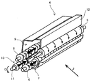
図4は現像剤搬送路内の現像剤の流れを説明する現像装置4の斜視断面図である。図4中の各矢印は現像剤の移動方向を示している。
また、図5は、現像装置4内の現像剤の流れの模式図であり、図4と同様、図5中の各矢印は現像剤の移動方向を示している。
Next, the circulation of the developer in the three developer transport paths provided in the developing device 4 will be described.
FIG. 4 is a perspective sectional view of the developing device 4 for explaining the flow of the developer in the developer transport path. Each arrow in FIG. 4 indicates the moving direction of the developer.
5 is a schematic diagram of the flow of the developer in the developing device 4. Like FIG. 4, each arrow in FIG. 5 indicates the moving direction of the developer.

攪拌搬送路10から現像剤の供給を受けた供給搬送路9では、現像ローラ5に現像剤を供給しながら、供給スクリュ8の搬送方向下流側に現像剤を搬送する。そして、現像ローラ5に供給され、現像に用いられず供給搬送路9の搬送方向下流端まで搬送された余剰現像剤は第一仕切り壁133の余剰開口部92より攪拌搬送路10に供給される(図5中矢印E)。
現像ローラ5から回収搬送路7に送られ、回収スクリュ6によって回収搬送路7の搬送方向下流端まで搬送された回収現像剤は、第二仕切り壁134の回収開口部93より攪拌搬送路10に供給される(図5中矢印F)。
攪拌搬送路10では、供給された余剰現像剤と回収現像剤とを攪拌し、攪拌スクリュ11の搬送方向下流側に搬送し、搬送方向下流側端部に到達した現像剤は、第一仕切り壁133に設けられた供給開口部91より供給搬送路9に供給される(図5中矢印D)。
In the supply conveyance path 9 that has been supplied with the developer from the agitation conveyance path 10, the developer is conveyed downstream in the conveyance direction of the supply screw 8 while supplying the developer to the developing roller 5. Then, the excess developer that is supplied to the developing roller 5 and is not used for development and is transported to the downstream end in the transport direction of the supply transport path 9 is supplied to the stirring transport path 10 from the surplus opening 92 of the first partition wall 133. (Arrow E in FIG. 5).
The collected developer that is sent from the developing roller 5 to the collection conveyance path 7 and conveyed to the downstream end in the conveyance direction of the collection conveyance path 7 by the collection screw 6 enters the stirring conveyance path 10 from the collection opening 93 of the second partition wall 134. Supplied (arrow F in FIG. 5).
In the agitating and conveying path 10, the supplied excess developer and the collected developer are agitated, conveyed to the downstream side in the conveying direction of the agitating screw 11, and the developer reaching the downstream end in the conveying direction is separated from the first partition wall. It is supplied to the supply conveyance path 9 from the supply opening 91 provided at 133 (arrow D in FIG. 5).

攪拌搬送路10では攪拌スクリュ11によって、回収現像剤、余剰現像剤及び移送部で必要に応じて補給されるトナーを、回収搬送路7及び供給搬送路9内を搬送される現像剤とは逆方向に攪拌搬送する。そして、搬送方向下流側で連通している供給搬送路9の搬送方向上流側に攪拌された現像剤を移送する。
攪拌搬送路10の下方には、不図示のトナー濃度センサが設けられ、このトナー濃度センサのセンサ出力に基づいて不図示のトナー補給制御装置を作動し、不図示のトナー収容部から現像装置4へのトナー補給を行っている。
In the agitating and conveying path 10, the agitating screw 11 reverses the collected developer, excess developer, and the toner replenished as necessary in the transfer unit as opposed to the developer conveyed in the collecting and conveying path 7 and the supply conveying path 9. Stir in the direction. Then, the agitated developer is transferred to the upstream side in the conveyance direction of the supply conveyance path 9 communicating with the downstream side in the conveyance direction.
A toner concentration sensor (not shown) is provided below the agitation transport path 10, and a toner supply control device (not shown) is operated based on the sensor output of the toner concentration sensor. Toner is being replenished.

図5に示す現像装置4では、供給搬送路9と回収搬送路7とを備え、現像剤の供給と回収とを異なる現像剤搬送路で行うので、現像済みの現像剤が供給搬送路9に混入することがない。このため、供給搬送路9の搬送方向下流側ほど現像ローラ5に供給される現像剤のトナー濃度が低下することを防止することができる。また、回収搬送路7と攪拌搬送路10とを備え、現像剤の回収と攪拌とを異なる現像剤搬送路で行うので、現像済みの現像剤が攪拌の途中に落ちることがない。これにより、十分に攪拌がなされた現像剤が供給搬送路9に供給されるため、供給搬送路9に供給されるの現像剤が攪拌不足となることを防止することができる。このように、供給搬送路9内の現像剤のトナー濃度が低下することを防止し、供給搬送路9内の現像剤が攪拌不足となることを防止することができるので現像時の画像濃度を一定にすることができる。   In the developing device 4 shown in FIG. 5, a supply conveyance path 9 and a recovery conveyance path 7 are provided, and developer supply and collection are performed in different developer conveyance paths, so that the developed developer is supplied to the supply conveyance path 9. There is no contamination. For this reason, it is possible to prevent the toner concentration of the developer supplied to the developing roller 5 from decreasing toward the downstream side of the supply conveyance path 9 in the conveyance direction. Further, since the recovery conveyance path 7 and the agitation conveyance path 10 are provided and the developer recovery and agitation are performed in different developer conveyance paths, the developed developer does not fall during the agitation. Thereby, since the sufficiently stirred developer is supplied to the supply conveyance path 9, it is possible to prevent the developer supplied to the supply conveyance path 9 from being insufficiently stirred. In this way, the toner density of the developer in the supply conveyance path 9 can be prevented from decreasing, and the developer in the supply conveyance path 9 can be prevented from being insufficiently stirred. Can be constant.

また、図5に示すように、現像装置4の下部から上部への現像剤の移動は矢印Dのみである。矢印Dで示す現像剤の移動は、攪拌スクリュ11の回転による搬送力で現像剤を攪拌搬送路10の下流側端部に押し込むことにより、現像剤を盛り上がらせて供給搬送路9に現像剤を供給するものである。
このように、現像剤を下方から上方に持ち上げる際に現像剤を押し込んで移動させと、現像剤にストレスを与えることになり、現像剤の寿命低下の一因となる。具体的には、現像剤中のキャリアの膜削れやトナーのスペント化がその個所で発生し、それに伴い画像品質の安定性が保たれなくなってしまう。
Further, as shown in FIG. 5, the movement of the developer from the lower part to the upper part of the developing device 4 is only the arrow D. The movement of the developer indicated by the arrow D is performed by pushing the developer into the downstream end of the agitating and conveying path 10 by the conveying force generated by the rotation of the agitating screw 11, thereby raising the developer and supplying the developer to the supply conveying path 9. To supply.
As described above, when the developer is pushed up and moved when the developer is lifted from the lower side to the upper side, the developer is stressed, which causes a decrease in the life of the developer. Specifically, carrier film scraping or toner spent in the developer occurs at the location, and accordingly, the stability of the image quality cannot be maintained.

このため、図5中の矢印Dで示す現像剤の移動における現像剤のストレスを軽減することで現像剤の長寿命化を図ることが出来る。現像剤の長寿命化を図ることにより、現像剤の劣化を防止して常に画像濃度ムラの無い画像品質の安定した現像装置を提供することができる。   For this reason, the life of the developer can be extended by reducing the stress of the developer in the movement of the developer indicated by the arrow D in FIG. By prolonging the life of the developer, it is possible to provide a developing device that prevents deterioration of the developer and is always stable in image quality without image density unevenness.

本実施形態の現像装置4では、図3に示すように、供給搬送路9を攪拌搬送路10の斜め上方になるように配置している。斜め上方に配置することにより、供給搬送路9を攪拌搬送路10の垂直上方に設け現像剤を持ち上げるものに比べて、矢印Dで示す現像剤の移動における現像剤のストレスを軽減することができる。   In the developing device 4 of the present embodiment, as shown in FIG. 3, the supply conveyance path 9 is disposed obliquely above the stirring conveyance path 10. By disposing it obliquely above, it is possible to reduce the developer stress in the movement of the developer indicated by the arrow D, compared to the case where the supply conveyance path 9 is provided vertically above the stirring conveyance path 10 and the developer is lifted. .

さらに、現像装置4では、供給搬送路9と攪拌搬送路10とを斜めに配置することで、図3に示すように、攪拌搬送路10の上部壁面が供給搬送路9の下部壁面よりも高い位置となるように配置している。
供給搬送路9を攪拌搬送路10に対して垂直上方に持ち上げることは、重力に逆らって現像剤を攪拌スクリュ11の圧によって持ち上げるので現像剤にストレスがかかる。一方、攪拌搬送路10の上部壁面が供給搬送路9の下部壁面よりも高い位置となるように配置することで、攪拌搬送路10の最高点に存在する現像剤が供給搬送路9の最下点に重力に逆らわず流れ込むことができる。これにより、現像剤にかかるストレスを低減することができる。
Further, in the developing device 4, the supply conveyance path 9 and the agitation conveyance path 10 are arranged obliquely so that the upper wall surface of the agitation conveyance path 10 is higher than the lower wall surface of the supply conveyance path 9 as shown in FIG. 3. It arranges so that it may become a position.
Lifting the supply conveyance path 9 vertically upward with respect to the stirring conveyance path 10 causes the developer to be stressed because the developer is lifted by the pressure of the stirring screw 11 against gravity. On the other hand, the developer present at the highest point of the agitating and conveying path 10 is placed at the bottom of the supplying and conveying path 9 by arranging the upper wall surface of the agitating and conveying path 10 to be higher than the lower wall surface of the supplying and conveying path 9. Can flow into a point without going against gravity. Thereby, the stress concerning a developing agent can be reduced.

また、攪拌搬送路10の現像剤搬送路下流側の、攪拌搬送路10と供給搬送路9とが連通している部分の攪拌スクリュ11の軸にフィン部材を設けても良い。このフィン部材は攪拌スクリュ11の軸方向に平行な辺と、攪拌スクリュの軸方向に垂直な辺とから構成される板状の部材である。このフィン部材で現像剤を掻き上げることにより、攪拌搬送路10から供給搬送路9へ、より効率的な現像剤の受渡しを行うことができる。   Further, a fin member may be provided on the shaft of the agitation screw 11 in a portion where the agitation conveyance path 10 and the supply conveyance path 9 communicate with each other on the downstream side of the developer conveyance path of the agitation conveyance path 10. This fin member is a plate-like member composed of a side parallel to the axial direction of the stirring screw 11 and a side perpendicular to the axial direction of the stirring screw. By scooping up the developer with this fin member, it is possible to more efficiently deliver the developer from the stirring conveyance path 10 to the supply conveyance path 9.

また、現像装置4では、図3に示すように、現像ローラ5と供給搬送路9との中心間距離Aが、現像ローラ5と攪拌搬送路10との中心間距離Bよりも短くなるように、供給搬送路9と攪拌搬送路10とを配置している。これにより供給搬送路9から現像ローラ5に現像剤を無理無く供給することができ、装置の小型化を図ることもできる。
また、攪拌スクリュ11は、図3中の手前側から見て反時計回り方向(図中矢印C方向)に回転しており、現像剤は攪拌スクリュ11の形状に沿って現像剤を持ち上げて供給搬送路9に移送させている。これにより、現像剤を効率良く持ち上げることが可能となり現像剤にかかるストレスをより低減することができる。
Further, in the developing device 4, as shown in FIG. 3, the center distance A between the developing roller 5 and the supply transport path 9 is shorter than the center distance B between the developing roller 5 and the stirring transport path 10. The supply conveyance path 9 and the stirring conveyance path 10 are arranged. As a result, the developer can be supplied without difficulty from the supply conveyance path 9 to the developing roller 5, and the apparatus can be downsized.
Further, the stirring screw 11 rotates in the counterclockwise direction (in the direction of arrow C in the figure) as viewed from the front side in FIG. 3, and the developer is supplied by lifting the developer along the shape of the stirring screw 11. It is transferred to the conveyance path 9. As a result, the developer can be lifted efficiently, and the stress applied to the developer can be further reduced.

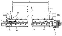
図6は、現像装置4の供給スクリュ8の回転中心における断面を図4中の矢印J方向から見た断面説明図である。図中Hは、現像剤担持体である現像ローラ5が、潜像担持体である感光体1にトナーを供給する現像領域を示している。この現像領域Hの現像ローラ5の回転軸の軸線方向の幅が現像領域幅αである。
図6に示すように、現像装置4は攪拌搬送路10から供給搬送路9に現像剤を持ち上げる箇所である供給開口部91と、供給搬送路9から攪拌搬送路10に現像剤を落下させる余剰開口部92とがともに現像領域幅α内に設けられている。
FIG. 6 is a cross-sectional explanatory view of the cross section at the rotation center of the supply screw 8 of the developing device 4 as viewed from the direction of arrow J in FIG. In the figure, H denotes a developing region in which the developing roller 5 that is a developer carrying member supplies toner to the photosensitive member 1 that is a latent image carrying member. The width in the axial direction of the rotation axis of the developing roller 5 in the developing area H is the developing area width α.
As shown in FIG. 6, the developing device 4 has a supply opening 91 that is a place where the developer is lifted from the agitation conveyance path 10 to the supply conveyance path 9, and a surplus that drops the developer from the supply conveyance path 9 to the agitation conveyance path 10. Both of the openings 92 are provided in the development region width α.

図7は、図5とは異なり、供給開口部91と余剰開口部92とを現像領域幅αの外側に設けた構成の現像装置4内の現像剤の流れの模式図である。
図7に示す現像装置4では、供給開口部91を現像領域幅αの外側に設けているため、供給搬送路9の搬送方向上流側は現像ローラ5よりも供給搬送路上流側領域β分長くなっている。また、余剰開口部92を現像領域幅αの外側に設けているため、供給搬送路9の搬送方向下流側は現像ローラ5よりも供給搬送路下流側領域γ分長くなっている。
FIG. 7 is a schematic diagram of the developer flow in the developing device 4 having a configuration in which the supply opening 91 and the surplus opening 92 are provided outside the development region width α, unlike FIG.
In the developing device 4 shown in FIG. 7, since the supply opening 91 is provided outside the development region width α, the upstream side in the transport direction of the supply transport path 9 is longer than the developing roller 5 by the upstream transport path region β. It has become. Further, since the surplus opening 92 is provided outside the developing region width α, the downstream side in the transport direction of the supply transport path 9 is longer than the developing roller 5 by the region γ on the downstream side of the supply transport path.

一方、図5に示す構成の現像装置4では、供給開口部91を現像領域幅α内に設けているため、供給搬送路9の搬送方向上流側は図7の現像装置4よりも供給搬送路上流側領域β分短くすることができる。また、余剰開口部92を現像領域幅α内に設けているため、供給搬送路9の搬送方向下流側は図7の現像装置4よりも供給搬送路下流側領域γ分短くすることができる。
このように、図5の現像装置4は供給開口部91と余剰開口部92とを現像領域幅α内に設けているため、図7に示す現像装置4に比べて、現像装置4の上部の省スペース化を図ることが出来る。
On the other hand, in the developing device 4 having the configuration shown in FIG. 5, the supply opening 91 is provided in the developing region width α, and therefore, the upstream side in the transport direction of the supply transport path 9 is on the supply transport path than the developing device 4 in FIG. The flow side region β can be shortened. Further, since the surplus opening 92 is provided in the development area width α, the downstream side in the transport direction of the supply transport path 9 can be made shorter by the area γ on the downstream side of the supply transport path than the developing device 4 in FIG.
As described above, since the developing device 4 in FIG. 5 is provided with the supply opening 91 and the surplus opening 92 within the developing region width α, the developing device 4 in the upper part of the developing device 4 is compared with the developing device 4 shown in FIG. Space saving can be achieved.

次に、現像装置4の供給搬送路9、攪拌搬送路10及び回収搬送路7からなる現像剤搬送路へのトナーを補給する位置について説明する。図8は、現像装置4の外観斜視図である。
図8に示すように、現像装置4は、トナーを補給するトナー補給口95が攪拌スクリュ11を備える攪拌搬送路10の搬送方向上流端部の上方に設けられている。このトナー補給口95は現像ローラ5の幅方向端部よりも外側に設けてあるので、現像領域幅αよりも外側となっている。
Next, the position at which toner is supplied to the developer conveyance path including the supply conveyance path 9, the agitation conveyance path 10 and the collection conveyance path 7 of the developing device 4 will be described. FIG. 8 is an external perspective view of the developing device 4.
As shown in FIG. 8, in the developing device 4, a toner replenishing port 95 for replenishing toner is provided above the upstream end in the conveying direction of the agitating and conveying path 10 including the agitating screw 11. Since the toner replenishing port 95 is provided outside the end portion in the width direction of the developing roller 5, it is outside the developing region width α.

この、トナー補給口95を設けた箇所は供給搬送路9の搬送方向の延長線上であり、図7における供給搬送路下流側領域γの空いたスペースに該当する。余剰開口部92を現像領域幅α内に設けることで空いたスペースにトナー補給口95を設けることにより、現像装置4の小型化を図ることが出来る。
トナー補給口95としては、攪拌搬送路10の搬送方向上流端部の上方に限らず、回収搬送路7の下流端部の上方に設けても良い。
The portion where the toner replenishing port 95 is provided is on an extension line in the conveyance direction of the supply conveyance path 9 and corresponds to a vacant space in the downstream area γ of the supply conveyance path in FIG. Providing the toner replenishment port 95 in an empty space by providing the surplus opening 92 within the developing region width α makes it possible to reduce the size of the developing device 4.
The toner replenishing port 95 is not limited to a position above the upstream end of the agitation transport path 10 in the transport direction, and may be provided above the downstream end of the collection transport path 7.

また、回収搬送路7から攪拌搬送路10へ現像剤の受渡しを行う箇所である回収開口部93の真上にトナー補給口95を設けるようにしても良い。回収開口部93の真上のスペースも余剰開口部92を現像領域幅α内に設けることで空いたスペースであるので、この位置にトナー補給口95を設けることにより、現像装置4の小型化を図ることができる。さらに、受渡し部である回収開口部93では現像剤が混ざりやすいため、この位置で補給を行うことにより、効率よく現像剤の攪拌を行うことができる。   Further, a toner replenishing port 95 may be provided just above the collection opening 93 which is a place where the developer is transferred from the collection conveyance path 7 to the stirring conveyance path 10. Since the space directly above the collection opening 93 is also an empty space provided by providing the surplus opening 92 within the developing region width α, the toner replenishing port 95 is provided at this position to reduce the size of the developing device 4. Can be planned. Further, since the developer is likely to be mixed in the collection opening 93 that is a delivery portion, the developer can be efficiently stirred by replenishing at this position.

現像装置4は、図5を用いて説明したように、攪拌搬送路10の搬送方向下流端から供給搬送路9の搬送方向上流端に現像剤を受け渡す供給開口部91を現像領域幅α内に設けている。また、供給搬送路9の搬送方向下流端から攪拌搬送路10の搬送方向上流端に現像剤を受け渡す余剰開口部92を現像領域幅α内に設けている。このため、従来の現像装置4に比べて、現像装置4の上部の省スペース化を図ることが出来、現像装置4全体の省スペース化を図ることが出来る。
さらに、余剰開口部92を現像領域幅α内に設けることで空いたスペースにトナー補給口95を設けることにより、現像装置4の小型化を図ることが出来る。
As described with reference to FIG. 5, the developing device 4 includes a supply opening 91 that transfers the developer from the downstream end in the transport direction of the stirring transport path 10 to the upstream end in the transport direction of the supply transport path 9 within the development region width α. Provided. Further, a surplus opening 92 for delivering the developer from the downstream end in the transport direction of the supply transport path 9 to the upstream end in the transport direction of the stirring transport path 10 is provided in the development region width α. For this reason, compared with the conventional developing device 4, space saving of the upper part of the developing device 4 can be achieved, and space saving of the whole developing device 4 can be achieved.
Furthermore, by providing the toner replenishing port 95 in an empty space by providing the surplus opening 92 within the developing region width α, the developing device 4 can be downsized.

回収搬送路7から攪拌搬送路10への現像剤の受渡し部である回収開口部93の上方からトナー補給を行うことにより、効率よく現像剤の攪拌を行うことができる。
また、画像形成装置としての複写機500のプリンタ部100の現像手段として、現像装置4を備えることにより、装置全体の省スペース化を図ることが出来る。
By replenishing toner from above the collection opening 93, which is a developer delivery section from the collection conveyance path 7 to the agitation conveyance path 10, the developer can be efficiently agitated.
Further, by providing the developing device 4 as the developing means of the printer unit 100 of the copying machine 500 as an image forming apparatus, it is possible to save the space of the entire apparatus.

次に、現像装置4内の現像剤の入れ替えについて説明する。
現像剤補給手段である不図示のトナー補給制御装置は、不図示のトナー収容部内のトナーをトナー補給口95から現像装置4に補給する。本実施形態の現像装置4ではトナー補給口95からトナーとキャリアとを含む現像剤が補給される。以降、現像装置4に補給されるトナーとキャリアとが混合された現像剤を「プレミックストナー」と称する。
Next, replacement of the developer in the developing device 4 will be described.
A toner replenishment control device (not shown) that is a developer replenishing unit replenishes toner in a toner storage unit (not shown) to the developing device 4 from the toner replenishing port 95. In the developing device 4 of this embodiment, a developer including toner and a carrier is supplied from a toner supply port 95. Hereinafter, the developer in which the toner to be supplied to the developing device 4 and the carrier are mixed is referred to as “premix toner”.

現像装置4は、供給搬送路9内の現像剤が所定の嵩を越えた場合にその一部を現像装置4の外部に排出する現像剤排出口94と、現像剤排出口94から排出された現像剤を現像装置4の外部に搬送する排出搬送スクリュ2aを備えた排出搬送路2とを有する。排出搬送路2は、供給搬送路9の搬送方向下流側で仕切り壁135を挟んで供給搬送路9と隣り合うように配置され、現像剤排出口94は供給搬送路9と排出搬送路2とを連通するように仕切り壁135に設けられた開口部である。
本実施形態では、現像剤排出口94を供給搬送路9に設けているが、現像剤排出口94を設ける位置としては、装置内全体の現像剤量の増減に応じて現像剤の嵩が増減する位置であれば、回収搬送路7や攪拌搬送路10に設けてもよい。
In the developing device 4, when the developer in the supply conveyance path 9 exceeds a predetermined volume, a part of the developer is discharged to the outside of the developing device 4 and discharged from the developer discharging port 94. A discharge conveyance path 2 provided with a discharge conveyance screw 2a for conveying the developer to the outside of the developing device 4; The discharge conveyance path 2 is disposed on the downstream side in the conveyance direction of the supply conveyance path 9 so as to be adjacent to the supply conveyance path 9 with the partition wall 135 interposed therebetween, and the developer discharge port 94 is connected to the supply conveyance path 9 and the discharge conveyance path 2. Is an opening provided in the partition wall 135 so as to communicate with each other.
In this embodiment, the developer discharge port 94 is provided in the supply conveyance path 9. However, the position where the developer discharge port 94 is provided increases or decreases the volume of the developer according to the increase or decrease in the amount of developer in the entire apparatus. If it is a position to perform, you may provide in the collection conveyance path 7 or the stirring conveyance path 10.

次に、現像剤排出口94を備えた従来の現像装置4について説明する。
図19は、現像剤排出口94を備えた従来の現像装置4について、図3と同じ方向から見た供給搬送路9の搬送方向下流端近傍の現像装置4の断面説明図である。
供給搬送路9の搬送方向下流端近傍とは、例えば、供給搬送路9から攪拌搬送路10へと現像剤が受け渡される現像剤受渡し部と供給搬送路9の搬送方向で同位置となる箇所である。
Next, the conventional developing device 4 provided with the developer discharge port 94 will be described.
FIG. 19 is a cross-sectional explanatory view of the developing device 4 in the vicinity of the downstream end in the transport direction of the supply transport path 9 as viewed from the same direction as in FIG. 3 for the conventional developing device 4 provided with the developer discharge port 94.
The vicinity of the downstream end in the conveyance direction of the supply conveyance path 9 is, for example, a location where the developer is transferred from the supply conveyance path 9 to the stirring conveyance path 10 and the same position in the conveyance direction of the supply conveyance path 9. It is.

また、供給搬送路9内の供給スクリュ8の回転方向は、図4でいうところの右回り(矢印Mの方向)であって、現像ローラ5に対して現像剤を下方から持ち上げて供給する方向に回転している。ここで、供給スクリュ8の回転方向を左回りにし、現像剤を上から振り掛けるようにして現像ローラ5に現像剤を供給すると、現像剤が飛び散りながら現像ローラ5に供給される。一方、供給スクリュ8の回転方向を図4に示すように右回りにすると、現像剤がたまっている供給搬送路9の下方から現像剤を持ち上げるようにして現像ローラ5に現像剤が供給されるようになる。現像剤が飛び散るように供給するよりも、下方から持ち上げるようにして供給するほうが現像剤の供給性が安定するため、現像装置4では供給スクリュ8の回転方向を図4でいうところの右回りに設定している。   Further, the rotation direction of the supply screw 8 in the supply conveyance path 9 is clockwise (direction of arrow M) as shown in FIG. 4, and the developer is supplied to the developing roller 5 from below. It is rotating. Here, when the developer is supplied to the developing roller 5 so that the rotation direction of the supply screw 8 is counterclockwise and the developer is sprinkled from above, the developer is supplied to the developing roller 5 while being scattered. On the other hand, when the rotation direction of the supply screw 8 is clockwise as shown in FIG. 4, the developer is supplied to the developing roller 5 so as to lift the developer from below the supply conveyance path 9 where the developer is accumulated. It becomes like this. The developer supply performance is more stable when the developer is supplied from the lower side than when the developer is supplied so that the developer is scattered. Therefore, in the developing device 4, the rotation direction of the supply screw 8 is clockwise as shown in FIG. It is set.

特に本実施形態の現像装置4のように現像ローラ5に供給した現像剤を供給搬送路9へ戻さず、回収搬送路7で回収するものでは、現像剤量は供給搬送路9の下流に行くにしたがって減少していく。このため、現像剤がたまっている下方からくみ上げて現像ローラ5に供給するもののほうが現像剤の供給性の面では優れている。   In particular, in the case where the developer supplied to the developing roller 5 is not returned to the supply conveyance path 9 and is collected by the collection conveyance path 7 as in the developing device 4 of the present embodiment, the developer amount goes downstream of the supply conveyance path 9. It decreases according to. For this reason, it is more excellent in terms of developer supply that the developer is drawn up from below and supplied to the developing roller 5.

ここで、搬送力を付与されることで供給搬送路9内を移動する現像剤の勢いや、現像剤搬送スクリュである供給スクリュ8の回転する力によって供給搬送路9内の現像剤は飛び跳ねる。そして、図19に示すように、現像剤搬送路である供給搬送路9の所定の高さに現像剤排出口94を設けただけの構成であると、図19中の矢印Tで示すような経路で、飛び跳ねた現像剤が飛翔して現像剤排出口94を通過して排出されることがある。   Here, the developer in the supply conveyance path 9 jumps by the momentum of the developer moving in the supply conveyance path 9 by applying the conveyance force and the rotating force of the supply screw 8 that is a developer conveyance screw. As shown in FIG. 19, when the developer discharge port 94 is simply provided at a predetermined height of the supply conveyance path 9 that is the developer conveyance path, as shown by an arrow T in FIG. 19. On the path, the jumped developer may fly and pass through the developer discharge port 94 and be discharged.

現像剤が飛び跳ねて排出される場合、供給搬送路9内の現像剤排出口94を設けた位置を搬送される現像剤が適正な量の状態や、適正な量を下回る状態であっても、飛び跳ねた現像剤が排出されるおそれがある。このように飛び跳ねた現像剤が排出される状態であると、現像装置4内の現像剤が適正な量以下の状態であるにもかかわらず現像剤排出口94から現像剤が排出されることがある。これにより、現像装置4内の現像剤量が必要量を下回り、感光体1への現像剤の供給が不安定になるおそれがある。そして、感光体1への現像剤の供給が不安定になると画像抜けなどの異常画像が発生する。   When the developer jumps and is discharged, even if the developer transported through the position where the developer discharge port 94 in the supply transport path 9 is provided is in an appropriate amount or less than the appropriate amount, The jumped developer may be discharged. In this state where the developer that has jumped off is discharged, the developer may be discharged from the developer discharge port 94 even though the amount of the developer in the developing device 4 is less than an appropriate amount. is there. As a result, the amount of developer in the developing device 4 is less than the required amount, and the supply of developer to the photoreceptor 1 may become unstable. When the developer supply to the photosensitive member 1 becomes unstable, an abnormal image such as image omission occurs.

図19では、飛び跳ねた現像剤が現像剤排出口94に向かう経路を矢印Tで示した。図19中の矢印Tは、飛び跳ねた現像剤が現像剤排出口94に向かう経路を模式的に示したものであり、飛び跳ねた現像剤が現像剤排出口94に向かう経路としては矢印Tで示すものに限るものではない。   In FIG. 19, the arrow T indicates the path of the jumped developer toward the developer discharge port 94. An arrow T in FIG. 19 schematically shows a path of the jumped developer toward the developer discharge port 94, and a path of the jumped developer toward the developer discharge port 94 is indicated by an arrow T. It is not limited to things.

〔実施例1〕
次に、実施形態の現像装置4の特徴部を備えた一つ目の実施例(以下、「実施例1」と呼ぶ)について説明する。
図1は、実施例1の現像装置4の断面説明図である。
図1に示すように、実施例1の現像装置4は、飛翔現像剤排出抑制部材として、ブロック部材3を備えている。ブロック部材3は、現像剤搬送部材である供給スクリュ8が現像剤を搬送するために回転することによって飛翔した現像剤が現像剤排出口94に向かう経路(図19中矢印T)を塞ぐため、飛び跳ねた現像剤が排出されることを抑制できる。
[Example 1]
Next, a first example (hereinafter referred to as “Example 1”) including the characteristic portion of the developing device 4 of the embodiment will be described.
FIG. 1 is an explanatory cross-sectional view of the developing device 4 according to the first embodiment.
As shown in FIG. 1, the developing device 4 of Example 1 includes a block member 3 as a flying developer discharge suppressing member. The block member 3 closes the path (arrow T in FIG. 19) where the developer flying by the supply screw 8 being a developer conveying member rotating to convey the developer is directed to the developer discharge port 94. It is possible to suppress the splashed developer from being discharged.

また、現像装置4では、供給搬送路9内から現像剤排出口94に向かう現像剤が通過する排出経路96がブロック部材3と仕切り壁135との間に形成されている。これにより、飛び跳ねた現像剤が排出されることを抑制しつつ、現像装置4内の現像剤量が増加したときには、排出経路96によって現像剤を現像剤排出口94に案内し、必要量を超えた現像剤を現像剤排出口94から排出することができる。   Further, in the developing device 4, a discharge path 96 through which developer passes from the supply conveyance path 9 toward the developer discharge port 94 is formed between the block member 3 and the partition wall 135. Thus, when the amount of developer in the developing device 4 increases while suppressing the jumped developer from being discharged, the developer is guided to the developer discharge port 94 by the discharge path 96 and exceeds the required amount. The developer can be discharged from the developer discharge port 94.

さらに、実施例1の現像装置4は、排出経路96を閉鎖する閉鎖状態と、排出経路96を開放する開放状態とを選択的に取り得る排出経路開閉部材140を備える。
図1は、排出経路開閉部材140が排出経路96を閉じた閉鎖状態を示しておいる。図9は、図1と同様に実施例1の現像装置4の断面説明図であって、排出経路開閉部材140が排出経路96を開放した開放状態を示している。
Further, the developing device 4 according to the first embodiment includes a discharge path opening / closing member 140 that can selectively take a closed state in which the discharge path 96 is closed and an open state in which the discharge path 96 is opened.
FIG. 1 shows a closed state in which the discharge path opening / closing member 140 closes the discharge path 96. FIG. 9 is a cross-sectional explanatory view of the developing device 4 according to the first embodiment, as in FIG. 1, and shows an open state in which the discharge path opening / closing member 140 opens the discharge path 96.

図10は、実施例1の現像装置4を図1中の手前側の斜め上方から見た斜視断面図であり、断面は現像剤排出口94を設けた位置における断面である。また、図11は、図10に示す状態から排出経路開閉部材140を取り外した状態の斜視断面図である。   FIG. 10 is a perspective cross-sectional view of the developing device 4 according to the first exemplary embodiment as viewed obliquely from the front side in FIG. 1, and the cross-section is a cross-section at a position where the developer discharge port 94 is provided. FIG. 11 is a perspective sectional view of the state where the discharge path opening / closing member 140 is removed from the state shown in FIG.

図12は、実施例1の現像装置4を図1中の奥側の斜め上方から見た斜視断面図であり、断面は現像剤排出口94を設けた位置における断面である。図12は、図10及び図11に示す現像装置4に対して、現像装置4を形成するケーシングのうちの現像ドクタ12が固定されるドクタ固定ケーシング12aと、現像ローラ5と、現像ドクタ12と、を取り外した状態の斜視断面図である。また、図13は、図12に示す状態から排出経路開閉部材140を取り外した状態の斜視断面図である。   12 is a perspective cross-sectional view of the developing device 4 according to the first exemplary embodiment when viewed from the obliquely upper side on the back side in FIG. 1, and the cross-section is a cross-section at a position where the developer discharge port 94 is provided. FIG. 12 shows a developing device 4 shown in FIGS. 10 and 11, a doctor fixing casing 12 a to which the developing doctor 12 of the casings forming the developing device 4 is fixed, the developing roller 5, and the developing doctor 12. It is a perspective sectional view of the state where, was removed. FIG. 13 is a perspective sectional view of the state where the discharge path opening / closing member 140 is removed from the state shown in FIG.

図14は、実施例1の現像装置4を図1中の奥側の斜め下方から見た斜視断面図であり、断面は現像剤排出口94を設けた位置よりも供給搬送路9における搬送方向上流側(図1中の奥側)における断面である。図14は、図12及び図13に示す現像装置4に対して、供給スクリュ8を取り外した状態の斜視断面図である。また、図15は、図14に示す状態から排出経路開閉部材140を取り外した状態の斜視断面図である。   14 is a perspective cross-sectional view of the developing device 4 according to the first exemplary embodiment when viewed from the obliquely lower side on the back side in FIG. It is a cross section in the upstream (back side in FIG. 1). 14 is a perspective sectional view of the developing device 4 shown in FIGS. 12 and 13 with the supply screw 8 removed. FIG. 15 is a perspective sectional view of the state where the discharge path opening / closing member 140 is removed from the state shown in FIG.

排出経路開閉部材140は、シート状の弾性材料からなり、一端の上面をブロック部材3の下面に貼り付けて固定し、他端側の下面が現像剤排出口94の下端を形成する仕切り壁135の縁部に接触する。排出経路開閉部材140は一端を中心に他端が揺動可能で、閉鎖状態から他端側が持ち上がって開放状態となる。
図1に示すように、ブロック部材3の下面は、現像剤排出口94の下端を形成する仕切り壁135の縁部よりも下方にある。このため、図1に示す閉鎖状態では、排出経路開閉部材140はブロック部材3の下面に固定された一端側に対して上方に撓んだ状態で仕切り壁135の縁部に接触する。このとき、排出経路開閉部材140の自重と撓みに対する反発力によって他端側を仕切り壁135の縁部に押し付けるような付勢力が作用する。
The discharge path opening / closing member 140 is made of a sheet-like elastic material, and is attached to the lower surface of the block member 3 by fixing the upper surface of one end thereof, and the lower wall of the other end side forms a partition wall 135 that forms the lower end of the developer discharge port 94. Touch the edge of the. The other end of the discharge path opening / closing member 140 can swing around one end, and the other end side is lifted from the closed state to the open state.
As shown in FIG. 1, the lower surface of the block member 3 is below the edge of the partition wall 135 that forms the lower end of the developer discharge port 94. For this reason, in the closed state shown in FIG. 1, the discharge path opening / closing member 140 contacts the edge of the partition wall 135 in a state of being bent upward with respect to one end side fixed to the lower surface of the block member 3. At this time, a biasing force acts to press the other end side against the edge of the partition wall 135 by the repulsive force against the dead weight and the bending of the discharge path opening / closing member 140.

ブロック部材3を配置しても、ブロック部材3の下方で飛び跳ねた現像剤が排出経路96を通過して現像剤排出口94から排出されるおそれがある。実施例1の現像装置4では、ブロック部材3の下方で現像剤が飛び跳ねても排出経路開閉部材140の下面に現像剤がぶつかる。このとき、現像剤が排出経路開閉部材140を押し上げる力が上記付勢力よりも小さい状態では、排出経路開閉部材140は閉鎖状態を維持し、現像剤が排出されることを防止できる。一方、現像剤が排出経路開閉部材140を押し上げる力が上記付勢力よりも大きくなると、排出経路開閉部材140の他端側(図1中の左側)が現像剤に押し上げられ、図9に示すような開放状態となる。開放状態となると、供給搬送路9内の現像剤の一部が排出経路96を通過して現像剤排出口94から排出搬送路2に到達し、現像装置4の外部に排出される。   Even if the block member 3 is arranged, the developer jumped below the block member 3 may pass through the discharge path 96 and be discharged from the developer discharge port 94. In the developing device 4 according to the first embodiment, even when the developer jumps below the block member 3, the developer collides with the lower surface of the discharge path opening / closing member 140. At this time, when the force by which the developer pushes up the discharge path opening / closing member 140 is smaller than the urging force, the discharge path opening / closing member 140 is kept closed, and the developer can be prevented from being discharged. On the other hand, when the force by which the developer pushes up the discharge path opening / closing member 140 becomes larger than the biasing force, the other end side (left side in FIG. 1) of the discharge path opening / closing member 140 is pushed up by the developer, as shown in FIG. Open. In the open state, a part of the developer in the supply conveyance path 9 passes through the discharge path 96, reaches the discharge conveyance path 2 from the developer discharge port 94, and is discharged to the outside of the developing device 4.

供給搬送路9内の現像剤が排出経路開閉部材140を押し上げる力は、供給搬送路9における現像剤排出口94近傍の現像剤量によって変動する。現像剤量が少なく、現像剤の剤面が排出経路開閉部材140の下面に届いておらず、排出経路開閉部材140の下面にぶつかる現像剤が少ない状態では、現像剤が排出経路開閉部材140を押し上げる力は小さく、排出経路開閉部材140は閉鎖状態のままとなる。   The force with which the developer in the supply conveyance path 9 pushes up the discharge path opening / closing member 140 varies depending on the amount of developer in the vicinity of the developer discharge port 94 in the supply conveyance path 9. In a state where the amount of the developer is small, the developer surface does not reach the lower surface of the discharge path opening / closing member 140, and the developer that hits the lower surface of the discharge path opening / closing member 140 is small, the developer moves the discharge path opening / closing member 140. The pushing-up force is small, and the discharge path opening / closing member 140 remains closed.

一方、現像装置4内の現像剤量が増加し、現像剤排出口94近傍の現像剤量が増加すると、現像剤の嵩が大きくなり、剤面が排出経路開閉部材140の下面に到達する。さらに、現像剤の嵩が大きくなると、現像剤が排出経路開閉部材140を押し上げて開放状態となり、現像剤排出口94から現像剤が排出される。   On the other hand, when the amount of developer in the developing device 4 increases and the amount of developer in the vicinity of the developer discharge port 94 increases, the volume of the developer increases, and the agent surface reaches the lower surface of the discharge path opening / closing member 140. Further, when the bulk of the developer increases, the developer pushes up the discharge path opening / closing member 140 to be in an open state, and the developer is discharged from the developer discharge port 94.

また、現像剤の剤面が排出経路開閉部材140の下面に到達した場合に限らず、開放状態となることが考えられる。すなわち、現像剤排出口94近傍の現像剤量が多くなると、飛び跳ねて排出経路開閉部材140の下面にぶつかる現像剤の量も増加し、現像剤が排出経路開閉部材140を押し上げる力も増加する。そして、現像剤の剤面が排出経路開閉部材140の下面に到達していない状態であっても、飛び跳ねた現像剤が排出経路開閉部材140の下面を押し上げる力が上記付勢力よりも大きくなると、排出経路開閉部材140の他端側が持ち上がり、開放状態となる。   In addition, the developer surface is not limited to the case where the developer surface reaches the lower surface of the discharge path opening / closing member 140, but may be in an open state. That is, as the amount of developer near the developer discharge port 94 increases, the amount of developer that jumps and hits the lower surface of the discharge path opening / closing member 140 also increases, and the force by which the developer pushes up the discharge path opening / closing member 140 also increases. Even when the developer surface of the developer does not reach the lower surface of the discharge path opening / closing member 140, the force by which the jumped developer pushes up the lower surface of the discharge path opening / closing member 140 is greater than the biasing force. The other end side of the discharge path opening / closing member 140 is lifted and opened.

現像剤の剤面が排出経路開閉部材140を押し上げる場合と、飛び跳ねた現像剤が排出経路開閉部材140を押し上げる場合との何れの場合であっても、供給搬送路9内の現像剤排出口94を設けた位置における現像剤量が少ない場合には閉鎖状態となる。そして、この位置における現像剤量が増加し、現像剤が排出経路開閉部材140を押し上げることにより、開放状態となって現像剤の排出を行うことができる。
この構成により、飛び跳ねて機外に放出される現像剤を排出経路開閉部材140で押さえ、現像剤の流動性や飛び跳ねによる排出量の誤差を減らし、現像装置4内の現像剤の量が一定量を超えたときに現像剤を排出する構成を実現できる。
In both cases where the developer surface pushes up the discharge path opening / closing member 140 and when the splashed developer pushes up the discharge path opening / closing member 140, the developer discharge port 94 in the supply conveyance path 9. When the amount of developer at the position where is provided is small, the closed state is obtained. Then, the developer amount at this position increases, and the developer pushes up the discharge path opening / closing member 140, so that the developer can be discharged and discharged.
With this configuration, the developer that jumps out and is released to the outside of the apparatus is pressed by the discharge path opening / closing member 140, the developer fluidity and the discharge error due to the jump are reduced, and the amount of developer in the developing device 4 is constant. It is possible to realize a configuration in which the developer is discharged when the value exceeds the value.

現像装置4のように、供給搬送路9内の現像剤排出口94を設けた位置における現像剤量の変化に応じて現像剤排出口94へ向かう排出経路96の開閉を行うことによって、現像剤量が少ない状態で飛び跳ねた現像剤が排出されることを防止できる。よって、現像装置4内の現像剤量が増加していないにもかかわらず現像剤が排出されることを防止することができる。このため、現像装置4内の現像剤の必要量を確保することができ、感光体1に安定した現像剤の供給を行うことができる。これにより、感光体1上の静電潜像を良好にトナー像化することができ、画像抜けなどの異常画像の発生を防止し、良好な画像形成を行うことができる。   As in the developing device 4, the developer is opened and closed by opening and closing a discharge path 96 toward the developer discharge port 94 in accordance with a change in the developer amount at a position where the developer discharge port 94 is provided in the supply conveyance path 9. It is possible to prevent the developer jumped in a small amount from being discharged. Accordingly, it is possible to prevent the developer from being discharged even though the amount of the developer in the developing device 4 has not increased. Therefore, the necessary amount of developer in the developing device 4 can be secured, and the developer can be stably supplied to the photoreceptor 1. As a result, the electrostatic latent image on the photoreceptor 1 can be favorably converted into a toner image, an abnormal image such as image omission can be prevented, and good image formation can be performed.

また、図1に示すように、閉鎖状態では排出経路開閉部材140の他端側が現像剤排出口94に入り込み、排出経路開閉部材140の下面が仕切り壁135における現像剤排出口94の下端部分に接触する。
排出経路開閉部材140の揺動中心となる一端の位置が、組み付け誤差によって現像剤排出口94から多少離れても、閉鎖状態で排出経路開閉部材140が現像剤排出口94に入り込む範囲の誤差であれば閉鎖状態で現像剤が通過し得る隙間は生じない。また、上記一端の位置が組み付け誤差によって現像剤排出口94に多少近付いても、他端が排出搬送路2の内壁面等の他の部材に接触することなく現像剤排出口94に入り込む長さが変化するだけの範囲の誤差であれば、円滑な開閉動作を行うことができる。このように、排出経路開閉部材140の一端の位置に組み付け誤差が生じても、ある程度の誤差の範囲であれば、閉鎖状態で隙間が生じることを防止し、且つ、円滑な開閉動作を行うことができるので、組み付け公差を広く設定することができる。よって、装置内の現像剤量が増加していないにもかかわらず現像剤が排出されることを抑制するための排出経路開閉部材140の組み付け精度を従来よりも低くできる。
Further, as shown in FIG. 1, in the closed state, the other end side of the discharge path opening / closing member 140 enters the developer discharge port 94, and the lower surface of the discharge path opening / closing member 140 is at the lower end portion of the developer discharge port 94 in the partition wall 135. Contact.
Even if the position of one end serving as the swing center of the discharge path opening / closing member 140 is slightly separated from the developer discharge port 94 due to an assembly error, the error is within the range in which the discharge path opening / closing member 140 enters the developer discharge port 94 in the closed state. If so, there is no gap through which the developer can pass in the closed state. In addition, even if the position of the one end approaches the developer discharge port 94 somewhat due to an assembly error, the other end enters the developer discharge port 94 without contacting other members such as the inner wall surface of the discharge conveyance path 2. If the error is within a range that only changes, a smooth opening / closing operation can be performed. Thus, even if an assembly error occurs at the position of one end of the discharge path opening / closing member 140, a gap is prevented from being generated in a closed state and a smooth opening / closing operation is performed within a certain error range. As a result, assembly tolerances can be set widely. Therefore, the assembly accuracy of the discharge path opening / closing member 140 for suppressing the discharge of the developer even though the amount of the developer in the apparatus is not increased can be made lower than before.

また、図1に示すように、実施例1の現像装置4は、ブロック部材3の下面に排出経路開閉部材140を貼り付ける構成となっている。このような構成では、現像剤が排出経路開閉部材140を下方から押圧したときに、排出経路開閉部材140をブロック部材3の下面に押し付ける方向に力が作用する。これにより、排出経路開閉部材140が現像剤によって押し上げられてもブロック部材3から剥がれ難い構成を実現出来る。   As shown in FIG. 1, the developing device 4 according to the first embodiment has a configuration in which a discharge path opening / closing member 140 is attached to the lower surface of the block member 3. In such a configuration, when the developer presses the discharge path opening / closing member 140 from below, a force acts in a direction to press the discharge path opening / closing member 140 against the lower surface of the block member 3. Thereby, even if the discharge path opening / closing member 140 is pushed up by the developer, it is possible to realize a configuration in which the discharge path opening / closing member 140 is hardly peeled off from the block member 3.

図20は、特許文献2に記載の排出経路開閉部材140を備えた現像装置の概略を説明する供給搬送路9近傍の拡大断面図である。この現像装置では、排出経路開閉部材140の図中右側の端部がブロック部材3に固定され、排出経路開閉部材140の図中左側の端部は自由端となっており、自由端側が現像剤に押し上げられる構成となっている。この現像装置では図20(a)に示すように、閉鎖状態では排出経路開閉部材140は現像剤排出口94の下方の仕切り壁135の壁面に接触または近接する構成となっている。   FIG. 20 is an enlarged cross-sectional view of the vicinity of the supply conveyance path 9 for explaining the outline of the developing device provided with the discharge path opening / closing member 140 described in Patent Document 2. In this developing apparatus, the end on the right side of the discharge path opening / closing member 140 in the figure is fixed to the block member 3, the end on the left side in the figure of the discharge path opening / closing member 140 is a free end, and the free end side is the developer. It is configured to be pushed up. In this developing device, as shown in FIG. 20A, the discharge path opening / closing member 140 is in contact with or close to the wall surface of the partition wall 135 below the developer discharge port 94 in the closed state.

現像装置のケーシングに排出経路開閉部材140を作業者が組みつけようとすると、±0.5[mm]程度の公差を設定することが求められる。このため、公差の範囲であっても排出経路開閉部材140の固定端から自由端までの長さが短いと、図20(b)に示すように、排出経路開閉部材140の磁有端と仕切り壁135との間に隙間が生じてしまう。隙間が生じると、隙間から排出経路開閉部材140の上方に回り込んだ現像剤によって排出経路開閉部材140が埋まってしまうおそれがある。   When an operator attempts to install the discharge path opening / closing member 140 in the casing of the developing device, it is required to set a tolerance of about ± 0.5 [mm]. For this reason, if the length from the fixed end to the free end of the discharge path opening / closing member 140 is short even within the tolerance range, as shown in FIG. A gap is generated between the wall 135 and the wall 135. If a gap is generated, the discharge path opening / closing member 140 may be filled with the developer that has flowed upward from the gap above the discharge path opening / closing member 140.

また、公差の範囲であっても排出経路開閉部材140の固定端から自由端までの長さが長いと、現像装置の動作中に、図20(c)に示すように、排出経路開閉部材140の先端が下側になるように巻き込まれてしまうおそれがある。図20(c)の状態となると、排出経路開閉部材140が持ち上がりにくくなり、現像剤の排出が阻害され、現像装置内に過剰な現像剤が収容された状態となるおそれがある。
これに対して、実施例1の現像装置4は、図1に示すように排出経路開閉部材140を配置することで、現像装置4に対する排出経路開閉部材140の組み付け誤差の影響を受け難い。
If the length from the fixed end to the free end of the discharge path opening / closing member 140 is long even within the tolerance range, the discharge path opening / closing member 140 is operated during operation of the developing device as shown in FIG. There is a risk of being caught so that the tip of the lower side is on the lower side. When the state shown in FIG. 20C is reached, the discharge path opening / closing member 140 is hardly lifted, the developer discharge is hindered, and there is a possibility that an excessive developer is contained in the developing device.
On the other hand, the developing device 4 according to the first embodiment is not easily affected by the assembly error of the discharge path opening / closing member 140 with respect to the developing device 4 by disposing the discharge path opening / closing member 140 as shown in FIG.

実施例1の現像装置4では、シート状の排出経路開閉部材140として、厚さが0.05[mm]のポリエチレンテレフタラートのシート材を用いているが、現像剤の増減によって開閉可能であればこれに限るものではない。   In the developing device 4 of the first embodiment, a polyethylene terephthalate sheet material having a thickness of 0.05 [mm] is used as the sheet-like discharge path opening / closing member 140. However, the sheet can be opened and closed by increasing or decreasing the developer. It is not limited to this.

図16は、実施例1の現像装置4の供給搬送路9の下流端近傍の拡大説明図である。現像装置4は、図14〜図16に示すように、現像剤排出口94に対して供給スクリュ8の搬送方向上流側に上流側壁部材38を備え、現像剤排出口94に対して供給スクリュ8の搬送方向下流側に下流側壁部材39を備える。上流側壁部材38は、供給スクリュ8の搬送方向(図16中矢印S)に垂直で、且つ、その法線方向が矢印S方向と逆方向となる上流側壁面38fを備える。下流側壁部材39は、供給スクリュ8の搬送方向(図16中矢印S)に垂直で、且つ、その法線方向が矢印S方向と同方向となる下流側壁面39fを備える。
上流側壁部材38及び下流側壁部材39は、排出経路開閉部材140の上流側と下流側とにおいて、排出経路開閉部材140の上面と供給搬送路9の天井との隙間を遮蔽する隙間遮蔽部材である。
FIG. 16 is an enlarged explanatory view of the vicinity of the downstream end of the supply conveyance path 9 of the developing device 4 according to the first embodiment. 14 to 16, the developing device 4 includes an upstream side wall member 38 on the upstream side in the transport direction of the supply screw 8 with respect to the developer discharge port 94, and the supply screw 8 with respect to the developer discharge port 94. The downstream side wall member 39 is provided on the downstream side in the transport direction. The upstream side wall member 38 includes an upstream side wall surface 38f that is perpendicular to the conveying direction of the supply screw 8 (arrow S in FIG. 16) and whose normal direction is opposite to the arrow S direction. The downstream side wall member 39 includes a downstream side wall surface 39f that is perpendicular to the conveying direction of the supply screw 8 (arrow S in FIG. 16) and whose normal direction is the same as the arrow S direction.
The upstream side wall member 38 and the downstream side wall member 39 are gap shielding members that shield the gap between the upper surface of the discharge path opening / closing member 140 and the ceiling of the supply conveyance path 9 on the upstream side and the downstream side of the discharge path opening / closing member 140. .

上流側壁部材38を備えることにより、現像剤排出口94に対して現像剤搬送方向上流側から、供給スクリュ8の搬送方向に飛翔した現像剤T1は、上流側壁部材38の上流側壁面38fに突き当たる。これにより、供給スクリュ8の軸方向のうち、搬送方向に飛翔した現像剤T1が排出経路開閉部材140の上方に向かう経路を塞ぐことができる。このため、搬送方向に飛翔した現像剤T1が閉鎖状態の排出経路開閉部材140の上方に到達することを防止し、閉鎖状態のときに現像剤排出口94から現像剤が排出されることを防止することができる。   By providing the upstream side wall member 38, the developer T <b> 1 flying in the transport direction of the supply screw 8 from the upstream side in the developer transport direction with respect to the developer discharge port 94 hits the upstream side wall surface 38 f of the upstream side wall member 38. . As a result, among the axial directions of the supply screw 8, the path of the developer T <b> 1 flying in the transport direction toward the upper side of the discharge path opening / closing member 140 can be blocked. Therefore, the developer T1 flying in the transport direction is prevented from reaching above the closed discharge path opening / closing member 140, and the developer is prevented from being discharged from the developer discharge port 94 in the closed state. can do.

また、下流側壁部材39を備えることにより、現像剤排出口94に対して現像剤搬送方向下流側から、供給スクリュ8の搬送方向とは逆方向に飛翔した現像剤T2は、下流側壁部材39の下流側壁面39fに突き当たる。これにより、供給スクリュ8の軸方向のうち、搬送方向とは逆方向に飛翔した現像剤T2が排出経路開閉部材140の上方に向かう経路を塞ぐことができる。このため、搬送方向とは逆方向に飛翔した現像剤T2が閉鎖状態の排出経路開閉部材140の上方に到達することを防止し、閉鎖状態のときに現像剤排出口94から現像剤が排出されることを防止することができる。   Further, by providing the downstream side wall member 39, the developer T <b> 2 flying in the direction opposite to the conveyance direction of the supply screw 8 from the downstream side in the developer conveyance direction with respect to the developer discharge port 94 is It strikes the downstream side wall surface 39f. As a result, of the axial direction of the supply screw 8, the developer T <b> 2 flying in the direction opposite to the transport direction can block the path toward the upper side of the discharge path opening / closing member 140. Therefore, the developer T2 flying in the direction opposite to the transport direction is prevented from reaching above the closed discharge path opening / closing member 140, and the developer is discharged from the developer discharge port 94 in the closed state. Can be prevented.

また、上流側壁部材38及び下流側壁部材39の下端である上流側壁下端部38e及び下流側壁下端部39eは、図15及び図16に示すように、現像剤排出口94の下端よりも下方に位置している。さらに、上流側壁下端部38e及び下流側壁下端部39eは、排出経路開閉部材140が固定されるブロック部材3の下面よりも下方に位置している。このように配置することにより、排出経路開閉部材140の上流側と下流側とにおいて、排出経路開閉部材140の上面と供給搬送路9の天井との隙間を遮蔽する構成を実現できる。   Further, the upstream side wall lower end 38e and the downstream side wall lower end 39e, which are lower ends of the upstream side wall member 38 and the downstream side wall member 39, are positioned below the lower end of the developer discharge port 94 as shown in FIGS. doing. Furthermore, the upstream side wall lower end part 38e and the downstream side wall lower end part 39e are located below the lower surface of the block member 3 to which the discharge path opening / closing member 140 is fixed. By arranging in this way, it is possible to realize a configuration that shields the gap between the upper surface of the discharge path opening / closing member 140 and the ceiling of the supply conveyance path 9 on the upstream side and the downstream side of the discharge path opening / closing member 140.

また、図14〜図16に示すように、下流側壁下端部39eは上流側壁下端部38eよりも下方に位置する。これにより、上流側壁下端部38eの下を通過した現像剤の一部が下流側壁部材39の上流側の壁面に突き当たり、排出経路開閉部材140の下面に向かうように上方に移動する。このような構成により、現像剤排出口94の近傍で現像剤を塞き止める作用が向上し、現像装置4内の現像剤量が増加したときの現像剤の排出の応答性が向上する。   Moreover, as shown in FIGS. 14-16, the downstream side wall lower end part 39e is located below the upstream side wall lower end part 38e. As a result, a part of the developer that has passed under the lower end portion 38e of the upstream side wall collides with the upstream side wall surface of the downstream side wall member 39 and moves upward so as to face the lower surface of the discharge path opening / closing member 140. With such a configuration, the action of blocking the developer in the vicinity of the developer discharge port 94 is improved, and the response of discharging the developer when the amount of developer in the developing device 4 is increased is improved.

また、図14及び図15に示すように、下流側壁部材39は、仕切り壁135に近い側ほど下流側壁下端部39eが下方に位置する形状となっている。すなわち、下流側壁部材39は仕切り壁135に近い側ほど上下方向に長い形状である。これにより、現像装置4内の現像剤量が増加したとき現像剤が排出経路開閉部材140を押し上げ易い構成としている。   Further, as shown in FIGS. 14 and 15, the downstream side wall member 39 has a shape in which the downstream side wall lower end portion 39 e is positioned downward toward the side closer to the partition wall 135. That is, the downstream side wall member 39 has a shape that is longer in the vertical direction toward the side closer to the partition wall 135. Thereby, when the amount of developer in the developing device 4 increases, the developer easily pushes up the discharge path opening / closing member 140.

上述したように、複写機500では、四つの画像形成ユニット20(Y,M,C,K)は、それぞれが扱うトナーの色が異なる点の他がほぼ同様の構成になっており、各画像形成ユニット20が備える四つの現像装置4もほぼ同様の構成となっている。
複写機500としては、扱うトナーの色によって、現像ローラ5と感光体1との隙間である現像ギャップの大きさを異ならせ、現像ギャップが大きい現像装置4にのみ排出経路開閉部材140を配置する構成としても良い。これは以下の理由による。
As described above, in the copier 500, the four image forming units 20 (Y, M, C, and K) have substantially the same configuration except that the colors of the toners handled by the image forming units 20 (Y, M, C, and K) are different. The four developing devices 4 included in the forming unit 20 have substantially the same configuration.
In the copying machine 500, the size of the developing gap, which is the gap between the developing roller 5 and the photosensitive member 1, is varied depending on the color of the toner to be handled, and the discharge path opening / closing member 140 is disposed only in the developing device 4 having a large developing gap. It is good also as a structure. This is due to the following reason.

すなわち、現像ギャップが小さいほど「ハロー画像」は生じにくいが、現像ギャップが小さいほど現像ローラ5と感光体1との回転によって生じるギャップ変動の影響による濃度ムラが目立ち易くなり、「ハロー画像」と濃度ムラとはトレードオフの関係にある。「ハロー画像」とは、ベタ画像のエッジ部分に生じるエッジ電界の影響を受けベタ画像に隣接するハーフトーン画像のドット再現性が悪化し白く抜けてしまう異常画像である。黒トナー像は現像ギャップの変動に起因する濃度ムラよりもハロー画像の方が異常画像として目立ち易く、他の色(Y,M,C)のトナー像はハロー画像よりも現像ギャップの変動に起因する濃度ムラの方が異常画像として目立ち易い傾向があった。
そこで、黒用画像形成ユニット20Kでは、ハロー画像の抑制を優先するために現像ギャップを小さく設定し、カラー用の画像形成ユニット20(Y,M,C)で濃度ムラの抑制を優先するために黒用よりも現像ギャップを大きく設定する。
That is, the smaller the development gap is, the less likely the “halo image” is to be generated, but the smaller the development gap is, the more easily the density unevenness due to the influence of the gap fluctuation caused by the rotation of the developing roller 5 and the photosensitive member 1 becomes conspicuous. There is a trade-off relationship with density unevenness. The “hello image” is an abnormal image in which the dot reproducibility of the halftone image adjacent to the solid image is deteriorated due to the influence of the edge electric field generated at the edge portion of the solid image, and is whitened. In the black toner image, the halo image is more noticeable as an abnormal image than the density unevenness due to the development gap variation, and the toner images of other colors (Y, M, C) are caused by the development gap variation than the halo image. The density unevenness tends to stand out as an abnormal image.
Therefore, in the black image forming unit 20K, in order to give priority to the suppression of the halo image, the development gap is set small, and in the color image forming unit 20 (Y, M, C), to give priority to the suppression of the density unevenness. The development gap is set larger than that for black.

現像ギャップを大きくする場合は、現像領域での現像ローラ5と感光体1との隙間を現像剤で埋めるため、現像領域に搬送する現像剤の量を多くする必要があり、現像ドクタ12と現像ローラ5との隙間であるドクタギャップも大きくする必要がある。ドクタギャップを大きくすると、供給搬送路9から現像ローラ5の表面に供給され、現像領域を通過して回収搬送路7に受け渡される現像剤の量が多くなり、供給搬送路9の上流側端部から下流側端部まで搬送される間の現像剤の減少量も多くなる。このため、現像ギャップの大きさに関わらず現像装置4の供給搬送路9内の現像剤の搬送速度を同じ速度とすると、現像ギャップが大きい現像装置4では供給搬送路9の下流側で現像剤が不足するおそれがある。このため、現像ギャップが大きい現像装置4では供給搬送路9内での現像剤の搬送速度を速くするために、現像ギャップが小さい現像装置4よりも供給スクリュ8の回転速度を速くする。   When the development gap is increased, the gap between the developing roller 5 and the photosensitive member 1 in the development area is filled with the developer, so it is necessary to increase the amount of the developer conveyed to the development area. It is also necessary to increase the doctor gap, which is a gap with the roller 5. When the doctor gap is increased, the amount of developer supplied from the supply conveyance path 9 to the surface of the developing roller 5 and passing through the development region and delivered to the collection conveyance path 7 increases. The amount of the developer decreased while being conveyed from the first portion to the downstream end portion is also increased. Therefore, if the developer conveyance speed in the supply conveyance path 9 of the developing device 4 is the same regardless of the size of the development gap, the developer on the downstream side of the supply conveyance path 9 in the development apparatus 4 having a large development gap. May be insufficient. For this reason, in the developing device 4 with a large developing gap, the rotational speed of the supply screw 8 is increased compared to the developing device 4 with a small developing gap in order to increase the developer conveying speed in the supply conveying path 9.

扱うトナーの色によって現像装置4の現像ギャップ及びドクタギャップの大きさと、供給スクリュ8の回転速度を異ならせても、現像装置4のケーシング等の他の部分は同じ構成とすることで、部品の共通化を図ることができる。このように他の部分を同じ構成とした場合、供給スクリュ8の回転速度が速い現像装置4の方が供給搬送路9内で飛び跳ねる現像剤の量が多くなる。このため、供給スクリュ8の回転速度が遅い黒用現像装置4Kでは排出経路開閉部材140を配置していない構成でも現像装置4内の現像剤の必要量を確保できても、回転速度が速い他の現像装置4では現像剤が過剰に排出され、必要量を確保できないことがあった。このような場合、供給スクリュ8の回転速度が速いカラー用の現像装置4(Y,M,C)にのみ排出経路開閉部材140を配置する。   Even if the size of the developing gap and the doctor gap of the developing device 4 and the rotation speed of the supply screw 8 are made different depending on the color of the toner to be handled, the other parts such as the casing of the developing device 4 have the same configuration, Can be shared. When the other parts have the same configuration in this way, the amount of developer that jumps in the supply conveyance path 9 is larger in the developing device 4 in which the rotation speed of the supply screw 8 is faster. For this reason, in the black developing device 4K in which the rotation speed of the supply screw 8 is slow, even if the discharge path opening / closing member 140 is not arranged, the required amount of developer in the developing device 4 can be secured, but the rotation speed is high. In the developing device 4, the developer is excessively discharged, and the required amount may not be ensured. In such a case, the discharge path opening / closing member 140 is disposed only in the color developing device 4 (Y, M, C) in which the rotation speed of the supply screw 8 is fast.

排出経路開閉部材140を配置することで供給スクリュ8の回転速度が速く、飛び跳ねる現像剤の量が多いカラー用の現像装置4(Y,M,C)であっても現像装置4内の現像剤の必要量を確保することが可能となる。
また、排出経路開閉部材140を配置していない構成でも現像装置4内の現像剤の必要量を確保できる黒用現像装置4Kに排出経路開閉部材140を配置すると、必要量を超えた現像剤を収容している状態にも関わらず現像剤が排出されないおそれがある。この場合、過剰な現像剤を収容した状態となり、現像剤搬送部材である各現像剤搬送スクリュの回転トルクが上昇したり、現像剤が漏れ出たりする、といった不具合が生じるおそれがある。これに対して、供給スクリュ8の回転速度が遅い黒用現像装置4Kのみ排出経路開閉部材140を配置しない構成とすることで、過剰な現像剤を収容した状態となることを防止し、上述した不具合の発生を防止できる。
By disposing the discharge path opening / closing member 140, even if the developing device 4 (Y, M, C) for color has a high rotational speed of the supply screw 8 and a large amount of developer jumps, the developer in the developing device 4 It is possible to secure the necessary amount of
Further, even if the discharge path opening / closing member 140 is not disposed, if the discharge path opening / closing member 140 is disposed in the black developing device 4K that can secure the necessary amount of developer in the developing device 4, the developer exceeding the necessary amount can be obtained. There is a possibility that the developer is not discharged in spite of the housed state. In this case, an excessive amount of developer is accommodated, and there is a risk that the rotational torque of each developer conveying screw, which is a developer conveying member, increases or the developer leaks out. On the other hand, the configuration in which the discharge path opening / closing member 140 is not disposed only in the black developing device 4K in which the rotation speed of the supply screw 8 is slow prevents the developer from being contained excessively, as described above. The occurrence of defects can be prevented.

〔実施例2〕
次に、実施形態の現像装置4の特徴部を備えた二つ目の実施例(以下、「実施例2」と呼ぶ)について説明する。
図17は、実施例2の現像装置4の断面説明図である。
実施例2の現像装置4は、ブロック部材3の形状と、排出経路開閉部材140の取り付け位置以外は実施例1と共通するため、共通する構成については説明を省略する。
図17に示すように、実施例2の現像装置4では排出経路開閉部材140は、シート状の弾性材料からなる。そして、排出経路開閉部材140は、現像剤排出口94の位置で下面となる面と同じ面の一端側をブロック部材3の側面に貼り付けて固定し、他端側が現像剤排出口94の下端を形成する仕切り壁135の縁部に接触している。
[Example 2]
Next, a second example (hereinafter referred to as “Example 2”) including the characteristic portion of the developing device 4 of the embodiment will be described.
FIG. 17 is a cross-sectional explanatory diagram of the developing device 4 according to the second embodiment.
Since the developing device 4 of the second embodiment is common to the first embodiment except for the shape of the block member 3 and the attachment position of the discharge path opening / closing member 140, the description of the common configuration is omitted.
As shown in FIG. 17, in the developing device 4 of Example 2, the discharge path opening / closing member 140 is made of a sheet-like elastic material. The discharge path opening / closing member 140 is fixed by attaching one end side of the same surface as the lower surface at the position of the developer discharge port 94 to the side surface of the block member 3 and fixing the other end side to the lower end of the developer discharge port 94. Is in contact with the edge of the partition wall 135 forming the.

図17に示すように、排出経路開閉部材140はブロック部材3の側面に固定された一端側に対して側方に撓んだ状態で仕切り壁135の縁部に接触し、撓みに対する反発力によって他端側を仕切り壁135の縁部に押し付けるような付勢力が作用する。
これにより、実施例1の現像装置4と同様に、供給搬送路9内の現像剤排出口94を設けた位置における現像剤量が少ない場合には閉鎖状態となる。そして、この位置における現像剤量が増加し、現像剤が排出経路開閉部材140を押し上げることにより、開放状態となって現像剤の排出を行うことができる。
この構成により、飛び跳ねて機外に放出される現像剤を排出経路開閉部材140で押さえ、現像剤の流動性や飛び跳ねによる排出量の誤差を減らし、現像装置4内の現像剤の量が一定量を超えたときに現像剤を排出する構成を実現できる。
As shown in FIG. 17, the discharge path opening / closing member 140 comes into contact with the edge of the partition wall 135 in a state where the discharge path opening / closing member 140 is bent laterally with respect to one end side fixed to the side surface of the block member 3, and the repulsive force against the bending causes An urging force that presses the other end against the edge of the partition wall 135 acts.
As a result, like the developing device 4 of the first embodiment, when the developer amount at the position where the developer discharge port 94 is provided in the supply conveyance path 9 is small, the closed state is established. Then, the developer amount at this position increases, and the developer pushes up the discharge path opening / closing member 140, so that the developer can be discharged and discharged.
With this configuration, the developer that jumps out and is released to the outside of the apparatus is pressed by the discharge path opening / closing member 140, the developer fluidity and the discharge error due to the jump are reduced, and the amount of developer in the developing device 4 is constant. It is possible to realize a configuration in which the developer is discharged when the value exceeds the value.

〔実施例3〕
次に、実施形態の現像装置4の特徴部を備えた三つ目の実施例(以下、「実施例3」と呼ぶ)について説明する。
図18は、実施例3の現像装置4の断面説明図である。
実施例3の現像装置4は、ブロック部材3の形状と、排出経路開閉部材140の取り付け位置、排出経路開閉部材140の材料、及び、排出経路開閉部材140の取り付け方法以外は実施例1と共通するため、共通する構成については説明を省略する。
Example 3
Next, a third example (hereinafter referred to as “Example 3”) including the characteristic portion of the developing device 4 of the embodiment will be described.
FIG. 18 is a cross-sectional explanatory view of the developing device 4 according to the third embodiment.
The developing device 4 of Example 3 is the same as that of Example 1 except for the shape of the block member 3, the attachment position of the discharge path opening / closing member 140, the material of the discharge path opening / closing member 140, and the method of attaching the discharge path opening / closing member 140. Therefore, the description of the common configuration is omitted.

実施例3の排出経路開閉部材140は、板状の剛性材料からなり、実施例1及び実施例2の排出経路開閉部材140とは異なり撓み難いものとなっている。実施例3では排出経路開閉部材140一端はヒンジ部140aを介してブロック部材3の側面に回動可能に取り付けて固定し、他端側の下面が現像剤排出口94の下端を形成する仕切り壁135の縁部に接触する。   The discharge path opening / closing member 140 of the third embodiment is made of a plate-like rigid material, and unlike the discharge path opening / closing member 140 of the first and second embodiments, it is difficult to bend. In the third embodiment, one end of the discharge path opening / closing member 140 is pivotally attached and fixed to the side surface of the block member 3 via the hinge part 140a, and the lower surface on the other end side forms a lower end of the developer discharge port 94. Contact the edge of 135.

図18に示すように、排出経路開閉部材140はブロック部材3の側面に配置したヒンジ部140aを中心に回動可能であるため、その自重によって他端側を上方から下方に仕切り壁135の縁部に押し付けるような付勢力が作用する。
これにより、実施例1の現像装置4と同様に、供給搬送路9内の現像剤排出口94を設けた位置における現像剤量が少ない場合には閉鎖状態となる。そして、この位置における現像剤量が増加し、現像剤が排出経路開閉部材140を押し上げることにより、開放状態となって現像剤の排出を行うことができる。
この構成により、飛び跳ねて機外に放出される現像剤を排出経路開閉部材140で押さえ、現像剤の流動性や飛び跳ねによる排出量の誤差を減らし、現像装置4内の現像剤の量が一定量を超えたときに現像剤を排出する構成を実現できる。
As shown in FIG. 18, the discharge path opening / closing member 140 is rotatable around a hinge part 140 a disposed on the side surface of the block member 3. An urging force that presses against the portion acts.
As a result, like the developing device 4 of the first embodiment, when the developer amount at the position where the developer discharge port 94 is provided in the supply conveyance path 9 is small, the closed state is established. Then, the developer amount at this position increases, and the developer pushes up the discharge path opening / closing member 140, so that the developer can be discharged and discharged.
With this configuration, the developer that jumps out and is released to the outside of the apparatus is pressed by the discharge path opening / closing member 140, the developer fluidity and the discharge error due to the jump are reduced, and the amount of developer in the developing device 4 is constant. It is possible to realize a configuration in which the developer is discharged when the value exceeds the value.

上述した実施形態は、本発明における最良の形態の一例であって、本願の特許請求の範囲を限定するものではない。また、上述した実施形態では本発明の構成を備えた現像装置40を備える画像形成装置が複写機である構成について説明したが、ファクシミリ、プリンタ等の他の画像形成装置にも適用可能である。   The embodiment described above is an example of the best mode of the present invention, and does not limit the scope of the claims of the present application. In the above-described embodiment, the configuration in which the image forming apparatus including the developing device 40 having the configuration of the present invention is a copying machine has been described. However, the present invention can also be applied to other image forming apparatuses such as a facsimile and a printer.

以上に説明したものは一例であり、本発明は、次の態様毎に特有の効果を奏する。
(態様A)
現像剤を表面上に担持する現像ローラ5等の現像剤担持体と、現像剤担持体に供給する現像剤を収容する供給搬送路9、回収搬送路7及び攪拌搬送路10等の現像剤収容部内の現像剤を搬送する供給スクリュ8、回収スクリュ6及び攪拌スクリュ11等の現像剤搬送部材と、を有し、現像剤収容部を形成する仕切り壁135等の収容部形成壁の所定の高さに、現像剤を装置外部に排出する現像剤排出口94等の現像剤排出口を設け、現像剤収容部内から現像剤排出口に向かう現像剤が通過する排出経路96等の排出経路を閉鎖する閉鎖状態と、排出経路を開放する開放状態とを選択的に取り得る排出経路開閉部材140等の排出経路開閉部材を備え、排出経路開閉部材は、一端を中心に他端が揺動可能で、閉鎖状態から他端側が持ち上がって開放状態となる現像装置において、閉鎖状態では排出経路開閉部材の他端側が現像剤排出口に入り込み、排出経路開閉部材の下面が収容部形成壁における現像剤排出口の下端部分に接触する。
これによれば、上記実施形態について説明したように、装置内の現像剤量が増加していないにもかかわらず現像剤が排出されることを抑制するための排出経路開閉部材の組み付け精度を従来よりも低くできる。これは以下の理由による。
すなわち、従来の排出経路開閉部材を備える現像装置では、排出経路開閉部材の一端の位置が組み付け誤差によって現像剤排出口から離れると、閉鎖状態であっても他端と壁面との間に現像剤が通過可能な隙間が出来てしまう。一方、態様Aでは、従来の現像装置において他端と壁面との間に現像剤が通過できるような隙間が生じるほどの組み付け誤差が生じても、閉鎖状態で排出経路開閉部材が現像剤排出口に入り込んだ状態を維持するように設定することが可能である。排出経路開閉部材が現像剤排出口に入り込んだ状態であれば、閉鎖状態で現像剤が通過し得る隙間は生じない。
また、従来の現像装置では、上記一端の位置が組み付け誤差によって現像剤排出口に近付くと、閉鎖状態のときに他端が壁面に突き当たって排出経路開閉部材が撓んだ状態となり、このときの撓み量が大きくなると、円滑な開閉動作を行えなくなる。一方、態様Aでは、従来の現像装置において排出経路開閉部材が撓んで円滑な開閉動作を行えなくなるほどの組み付け誤差が生じても、排出経路開閉部材の他端側が現像剤排出口に入り込む長さが長くなるだけであり、円滑な開閉動作の妨げとはならない。
このように態様Aでは、従来の現像装置においては許容されない組み付け誤差を許容することができるので、組み付け公差を広く設定することができる。よって、装置内の現像剤量が増加していないにもかかわらず現像剤が排出されることを抑制するための排出経路開閉部材の組み付け精度を従来よりも低くできる。
What has been described above is merely an example, and the present invention has a specific effect for each of the following modes.
(Aspect A)
A developer carrier such as a developing roller 5 carrying the developer on the surface, and a developer carrier such as a supply conveyance path 9, a recovery conveyance path 7 and a stirring conveyance path 10 for accommodating the developer supplied to the developer carrier. supply screw 8 for conveying the portion of the developer has a developer conveying member, such as a recovery screw 6 and agitation screw 11, a predetermined accommodating portion formation walls such as the partition wall 135 to form a current image containing portion At a height, a developer discharge port such as a developer discharge port 94 for discharging the developer to the outside of the apparatus is provided, and a discharge path such as a discharge path 96 through which the developer is directed from the inside of the developer container to the developer discharge port. Equipped with a discharge path opening / closing member such as a discharge path opening / closing member 140 that can selectively take a closed state for closing and an open state for opening the discharge path, and the other end of the discharge path opening / closing member can swing around one end. And the other end is lifted from the closed state In the developing device as a release state, the other end of the discharge passage controlling member in a closed state enters the developer discharge port, the lower surface of the discharge passage controlling member contacts the lower end portion of the developer discharge port in the housing section forming wall.
According to this, as described in the above embodiment, the assembly accuracy of the discharge path opening / closing member for suppressing the discharge of the developer even though the amount of the developer in the apparatus has not increased is conventionally increased. Can be lower. This is due to the following reason.
That is, in a developing device having a conventional discharge path opening / closing member, when the position of one end of the discharge path opening / closing member is separated from the developer discharge port due to an assembly error, the developer is between the other end and the wall surface even in the closed state. This will create a gap that can pass through. On the other hand, in the aspect A, even when an assembly error that causes a gap that allows the developer to pass between the other end and the wall surface occurs in the conventional developing device, the discharge path opening / closing member is closed in the closed state. It is possible to set to maintain the state of entering. If the discharge path opening / closing member enters the developer discharge port, there is no gap through which the developer can pass in the closed state.
Further, in the conventional developing device, when the position of the one end approaches the developer discharge port due to an assembly error, the other end abuts against the wall surface in the closed state, and the discharge path opening / closing member is bent. When the amount of deflection increases, smooth opening / closing operations cannot be performed. On the other hand, in aspect A, the length of the other end side of the discharge path opening / closing member that enters the developer discharge port even when an assembly error that causes the discharge path opening / closing member to bend and the smooth opening / closing operation cannot be performed in the conventional developing device occurs. Is only long and does not hinder smooth opening and closing operations.
As described above, in the aspect A, since an assembling error that is not allowed in the conventional developing device can be allowed, the assembling tolerance can be set widely. Therefore, the assembly accuracy of the discharge path opening / closing member for suppressing the discharge of the developer even though the amount of the developer in the apparatus is not increased can be made lower than before.

(態様B)
態様Aにおいて、現像剤排出口94等の現像剤排出口は、装置内全体の現像剤量の増減に応じて現像剤の嵩が増減する供給搬送路9等の現像剤収容部における位置に設けられている。
これによれば、上記実施形態について説明したように、現像装置4等の現像装置内の現像剤の量が一定量を超えたときに現像剤を排出する構成を実現できる。
(Aspect B)
In the aspect A, the developer discharge port such as the developer discharge port 94 is provided at a position in the developer accommodating portion such as the supply conveyance path 9 where the volume of the developer increases or decreases according to the increase or decrease of the developer amount in the entire apparatus. It has been.
According to this, as described in the above embodiment, it is possible to realize a configuration in which the developer is discharged when the amount of the developer in the developing device such as the developing device 4 exceeds a certain amount.

(態様C)
態様AまたはBの何れかの態様において、供給搬送路9等の現像剤収容部内の現像剤の搬送方向について、排出経路開閉部材140等の排出経路開閉部材の上流側と下流側とに、排出経路開閉部材の上面と現像剤収容部の天井との隙間を遮蔽する上流側壁部材38及び下流側壁部材39等の隙間遮蔽部材を備える。
これによれば、上記実施形態について説明したように、搬送方向に平行な方向に飛翔した現像剤が排出経路開閉部材140の上方に向かう経路を塞ぐことができる。このため、このため、搬送方向に平行な方向飛翔した現像剤が閉鎖状態の排出経路開閉部材の上方に到達することを防止し、閉鎖状態のときに現像剤排出口から現像剤が排出されることを防止することができる。
(Aspect C)
In any of the aspects A and B, the developer is discharged to the upstream side and the downstream side of the discharge path opening / closing member such as the discharge path opening / closing member 140 in the developer transport direction in the developer accommodating portion such as the supply transfer path 9. Gap shielding members such as an upstream side wall member 38 and a downstream side wall member 39 that shield a gap between the upper surface of the path opening / closing member and the ceiling of the developer accommodating portion are provided.
According to this, as described in the above embodiment, the developer flying in the direction parallel to the transport direction can block the route toward the upper side of the discharge route opening / closing member 140. For this reason, the developer flying in a direction parallel to the transport direction is prevented from reaching above the closed discharge path opening / closing member, and the developer is discharged from the developer discharge port in the closed state. This can be prevented.

(態様D)
態様Cにおいて、現像剤の搬送方向について排出経路開閉部材140等の排出経路開閉部材の下流側の下流側壁部材39等隙間遮蔽部材の下端部(下流側壁下端部39e)は、上流側の上流側壁部材38等の隙間遮蔽部材の下端部(上流側壁下端部38e)よりも下方に位置する。
これによれば、上記実施形態について説明したように、現像剤排出口94等の現像剤排出口94の近傍で現像剤を塞き止める作用が向上し、現像装置内の現像剤量が増加したときの現像剤の排出の応答性が向上する。
(Aspect D)
In aspect C, the lower end portion (downstream side wall lower end portion 39e) of the gap shielding member such as the downstream side wall member 39 on the downstream side of the discharge path opening / closing member such as the discharge path opening / closing member 140 in the developer transport direction is the upstream side wall on the upstream side. It is located below the lower end (upstream side wall lower end 38e) of the gap shielding member such as the member 38.
According to this, as described in the above embodiment, the action of blocking the developer in the vicinity of the developer discharge port 94 such as the developer discharge port 94 is improved, and the amount of developer in the developing device is increased. The responsiveness of the developer discharge at the time is improved.

(態様E)
態様A乃至Dの何れかの態様において、排出経路96等の排出経路を挟んで現像剤排出口94等の現像剤排出口と対向する位置にブロック部材3等の排出口対向部材を備え、排出経路開閉部材140等の排出経路開閉部材の一端側の上面を排出口対向部材の下面に貼り付けることで、排出経路開閉部材の一端を固定する。
これによれば、上記実施形態について説明したように、現像剤が排出経路開閉部材を押し上げたときに、排出経路開閉部材が排出口対向部材から剥がれ難い構成を実現することができる。
(Aspect E)
In any of the aspects A to D, a discharge port facing member such as the block member 3 is provided at a position facing the developer discharge port such as the developer discharge port 94 with the discharge path such as the discharge path 96 interposed therebetween, and the discharge One end of the discharge path opening / closing member is fixed by sticking the upper surface of one end side of the discharge path opening / closing member such as the path opening / closing member 140 to the lower surface of the discharge port facing member.
According to this, as described in the above embodiment, it is possible to realize a configuration in which when the developer pushes up the discharge path opening / closing member, the discharge path opening / closing member is not easily separated from the discharge port facing member.

(態様F)
態様A乃至Eの何れかの態様において、排出経路開閉部材140等の排出経路開閉部材は、閉鎖状態で撓んだ状態で縁部に接触するように配置され、閉鎖状態から開放状態となることで撓み量が大きくなる。
これによれば、上記実施形態について説明したように、閉鎖状態となるように付勢力を作用させることができ、現像剤量が少ないときに排出経路開閉部材を閉鎖状態で維持することができる。
(Aspect F)
In any of the aspects A to E, the discharge path opening / closing member such as the discharge path opening / closing member 140 is arranged so as to be in contact with the edge in a bent state in the closed state, and is changed from the closed state to the open state. Increases the amount of deflection.
According to this, as described in the above embodiment, the urging force can be applied so as to be in the closed state, and the discharge path opening / closing member can be maintained in the closed state when the amount of the developer is small.

(態様G)
感光体1等の潜像担持体と、潜像担持体表面を帯電させるための不図示の帯電装置等の帯電手段と、潜像担持体上に静電潜像を形成するための光書込ユニット21等の潜像形成手段と、静電潜像を現像する現像手段とを有する複写機500等の画像形成装置において、現像手段として、態様A乃至Fの何れかの態様に係る現像装置4等の現像装置を用いる。
これによれば、上記実施形態について説明したように、現像装置内の現像剤の必要量を確保することができ、感光体1等の潜像担持体に安定した現像剤の供給を行うことができる。これにより、潜像担持体上の静電潜像を良好にトナー像化することができ、画像抜けなどの異常画像の発生を防止し、良好な画像形成を行うことができる。
(Aspect G)
A latent image carrier such as the photosensitive member 1; charging means such as a charging device (not shown) for charging the surface of the latent image carrier; and optical writing for forming an electrostatic latent image on the latent image carrier. In an image forming apparatus such as a copying machine 500 having a latent image forming unit such as the unit 21 and a developing unit that develops an electrostatic latent image, the developing device 4 according to any one of modes A to F is used as the developing unit. Etc. is used.
According to this, as described in the above embodiment, the necessary amount of developer in the developing device can be ensured, and the developer can be stably supplied to the latent image carrier such as the photoreceptor 1. it can. As a result, the electrostatic latent image on the latent image carrier can be favorably converted into a toner image, the occurrence of abnormal images such as missing images can be prevented, and good image formation can be performed.

1 感光体
1K 黒用感光体
1Y イエロー用感光体
2 排出搬送路
2a 排出搬送スクリュ
3 ブロック部材
4 現像装置
4K 黒用現像装置
5 現像ローラ
6 回収スクリュ
7 回収搬送路
8 供給スクリュ
9 供給搬送路
10 攪拌搬送路
11 攪拌スクリュ
12 現像ドクタ
12a ドクタ固定ケーシング
14 張架ローラ
15 駆動ローラ
16 二次転写バックアップローラ
17 中間転写ユニット
20 画像形成ユニット
20K 黒用画像形成ユニット
21 光書込ユニット
22 二次転写装置
23 紙搬送張架ローラ
24 紙搬送ベルト
25 定着装置
26 定着ベルト
27 加圧ローラ
30 原稿台
32 コンタクトガラス
33 第一走行体
34 第二走行体
35 結像レンズ
36 読取センサ
38 上流側壁部材
38e 上流側壁下端部
38f 上流側壁面
39 下流側壁部材
39e 下流側壁下端部
39f 下流側壁面
42 給紙ローラ
43 ペーパーバンク
44 給紙カセット
45 分離ローラ
46 給紙路
47 搬送ローラ対
49 レジストローラ対
50 手差し給紙ローラ
51 手差しトレイ
52 手差し分離ローラ
53 手差し給紙路
56 排出ローラ
57 スタック部
62 一次転写バイアスローラ
90 ベルトクリーニング装置
91 供給開口部
92 余剰開口部
93 回収開口部
94 現像剤排出口
95 トナー補給口
96 排出経路
100 プリンタ部
110 中間転写ベルト
133 第一仕切り壁
134 第二仕切り壁
135 仕切り壁
140 排出経路開閉部材
140a ヒンジ部
200 給紙装置
300 スキャナ
400 原稿自動搬送装置
500 複写機
DESCRIPTION OF SYMBOLS 1 Photoconductor 1K Black photoconductor 1Y Yellow photoconductor 2 Discharge conveyance path 2a Discharge conveyance screw 3 Block member 4 Developing device 4K Black development device 5 Developing roller 6 Collection screw 7 Collection conveyance path 8 Supply screw 9 Supply conveyance path 10 Stirring conveyance path 11 Stirring screw 12 Developing doctor 12a Doctor fixed casing 14 Stretch roller 15 Drive roller 16 Secondary transfer backup roller 17 Intermediate transfer unit 20 Image forming unit 20K Black image forming unit 21 Optical writing unit 22 Secondary transfer device DESCRIPTION OF SYMBOLS 23 Paper conveyance tension roller 24 Paper conveyance belt 25 Fixing device 26 Fixing belt 27 Pressure roller 30 Document stand 32 Contact glass 33 First traveling body 34 Second traveling body 35 Imaging lens 36 Reading sensor 38 Upstream side wall member 38e Upstream side wall Lower end 38f Upstream Wall surface 39 Downstream side wall member 39e Downstream side wall lower end portion 39f Downstream side wall surface 42 Paper feed roller 43 Paper bank 44 Paper feed cassette 45 Separating roller 46 Paper feed path 47 Transport roller pair 49 Registration roller pair 50 Manual paper feed roller 51 Manual feed tray 52 Manual feed Separation roller 53 Manual feed path 56 Discharge roller 57 Stack section 62 Primary transfer bias roller 90 Belt cleaning device 91 Supply opening section 92 Excess opening section 93 Collection opening section 94 Developer discharge port 95 Toner supply port 96 Discharge path 100 Printer section 110 Intermediate transfer belt 133 First partition wall 134 Second partition wall 135 Partition wall 140 Discharge path opening / closing member 140a Hinge portion 200 Paper feeder 300 Scanner 400 Automatic document feeder 500 Copying machine

特許5037253号Japanese Patent No. 5037253 特許5277587号Japanese Patent No. 5277487

Claims (6)

現像剤を表面上に担持する現像剤担持体と、
前記現像剤担持体に供給する現像剤を収容する現像剤収容部内の現像剤を搬送する現像剤搬送部材と、を有し、
前記現像剤収容部を形成する収容部形成壁の所定の高さに、現像剤を装置外部に排出する現像剤排出口を設け、
前記現像剤収容部内から前記現像剤排出口に向かう現像剤が通過する排出経路を閉鎖する閉鎖状態と、前記排出経路を開放する開放状態とを選択的に取り得る排出経路開閉部材を備え、
前記排出経路開閉部材は、一端を中心に他端が揺動可能で、閉鎖状態から他端側が持ち上がることで開放状態となる現像装置において、
閉鎖状態では前記排出経路開閉部材の他端側が前記現像剤排出口に入り込み、前記排出経路開閉部材の下面が前記収容部形成壁における前記現像剤排出口の下端部分に接触し、
前記排出経路を挟んで前記現像剤排出口と対向する位置に排出口対向部材を備え、前記排出経路開閉部材の一端側の上面を前記排出口対向部材の下面に貼り付けることで、前記排出経路開閉部材の一端を固定することを特徴とする現像装置。
A developer carrying member for carrying the developer on the surface;
Anda developer carrying member for conveying the developer in the developer accommodating portion for accommodating a developer to be supplied to said developer carrying member,
At a predetermined height of the housing portion forming the wall that forms the developer accommodating portion, provided a developer discharge port for discharging the developer to the outside of the apparatus,
Wherein comprising a closed state to close the discharge path which the developer passes from developer housing toward the developer discharge port, the discharge passage controlling member that can be taken selectively an open state to open said discharge path,
In the developing device in which the discharge path opening and closing member is swingable around one end and opened by the other end being lifted from the closed state.
In the closed state enters the other end of the discharge passage controlling member within the developer discharge port, the lower surface of the discharge passage controlling member is in contact with the lower end portion of the developer discharge opening in the housing section forming wall,
A discharge port facing member is provided at a position facing the developer discharge port across the discharge route, and an upper surface on one end side of the discharge route opening / closing member is attached to a lower surface of the discharge port facing member, whereby the discharge route A developing device characterized in that one end of an opening / closing member is fixed .
請求項1の現像装置において、
前記現像剤排出口は、装置内全体の現像剤量の増減に応じて現像剤の嵩が増減する前記現像剤収容部における位置に設けられていることを特徴とする現像装置。
The developing device according to claim 1.
The developer outlet, a developing device, characterized in that provided at a position in said developer accommodating portion bulk of the developer increases or decreases according to the increase or decrease in the amount of developer throughout the device.
請求項1または2の現像装置において、
前記現像剤収容部内の現像剤の搬送方向について、前記排出経路開閉部材の上流側と下流側とに、前記排出経路開閉部材の上面と前記現像剤収容部の天井との隙間を遮蔽する隙間遮蔽部材を備えることを特徴とする現像装置。
The developing device according to claim 1 or 2,
The conveyance direction of the developer in the developer containing portion, a gap shielding the on the upstream side of the discharge passage controlling member and the downstream side, to shield the gap between the ceiling and the upper surface of the discharge passage controlling member the developer containing portion A developing device comprising a member.
請求項3の現像装置において、
現像剤の搬送方向について前記排出経路開閉部材の下流側の前記隙間遮蔽部材の下端部は、上流側の前記隙間遮蔽部材の下端部よりも下方に位置することを特徴とする現像装置
The developing device according to claim 3.
The lower end portion of the downstream side of the gap shielding member of the discharge passage controlling member for carrying direction of the developer, a developing device for being located lower than the lower end portion of the upstream side of the gap shielding member.
求項1乃至の何れかに記載の現像装置において、
前記排出経路開閉部材は、閉鎖状態で撓んだ状態で前記現像剤排出口の下端部分に接触するように配置され、閉鎖状態から開放状態となることで撓み量が大きくなることを特徴とする現像装置。
The developing device according to any one of Motomeko 1 to 4,
The discharge passage controlling member is arranged to contact the lower end portion of the developer discharge opening in a bent state in a closed state, wherein the amount of deflection by the open state from the closed state is increased Development device.
潜像担持体と、
前記潜像担持体表面を帯電させるための帯電手段と、
前記潜像担持体上に静電潜像を形成するための潜像形成手段と、
前記静電潜像を現像する現像手段とを有する画像形成装置において、
前記現像手段として、請求項1乃至の何れかに記載の現像装置を用いることを特徴とする画像形成装置。
A latent image carrier;
A charging means for charging said image bearing member surface,
A latent image forming means for forming an electrostatic latent image on said image bearing member,
In an image forming apparatus having a developing means for developing the electrostatic latent image,
Wherein as a developing unit, an image forming apparatus which comprises using a developing device according to any one of claims 1 to 5.
JP2014194048A 2014-09-24 2014-09-24 Developing device and image forming apparatus Active JP6440017B2 (en)

Priority Applications (1)

Application Number Priority Date Filing Date Title
JP2014194048A JP6440017B2 (en) 2014-09-24 2014-09-24 Developing device and image forming apparatus

Applications Claiming Priority (1)

Application Number Priority Date Filing Date Title
JP2014194048A JP6440017B2 (en) 2014-09-24 2014-09-24 Developing device and image forming apparatus

Publications (3)

Publication Number Publication Date
JP2016065952A JP2016065952A (en) 2016-04-28
JP2016065952A5 JP2016065952A5 (en) 2017-08-10
JP6440017B2 true JP6440017B2 (en) 2018-12-19

Family

ID=55805393

Family Applications (1)

Application Number Title Priority Date Filing Date
JP2014194048A Active JP6440017B2 (en) 2014-09-24 2014-09-24 Developing device and image forming apparatus

Country Status (1)

Country Link
JP (1) JP6440017B2 (en)

Families Citing this family (5)

* Cited by examiner, † Cited by third party
Publication number Priority date Publication date Assignee Title
JP7127307B2 (en) * 2018-03-16 2022-08-30 株式会社リコー Developing device, process cartridge, and image forming apparatus
JP7064172B2 (en) 2018-03-16 2022-05-10 富士フイルムビジネスイノベーション株式会社 Developing equipment and image forming equipment
JP7116911B2 (en) * 2018-07-27 2022-08-12 株式会社リコー PRESSING MEMBER, DEVELOPING DEVICE, PROCESS CARTRIDGE, AND IMAGE FORMING APPARATUS
JP7101345B2 (en) * 2018-07-27 2022-07-15 株式会社リコー Developing equipment, process cartridges, and image forming equipment
CN114104657A (en) * 2021-11-25 2022-03-01 湖北北新建材有限公司 Monitoring devices is carried to reamer powder is carried to pipe

Family Cites Families (4)

* Cited by examiner, † Cited by third party
Publication number Priority date Publication date Assignee Title
JP2003302834A (en) * 2002-04-11 2003-10-24 Canon Inc Developing device, process cartridge, and image forming apparatus
JP5277587B2 (en) * 2007-08-20 2013-08-28 株式会社リコー Image forming apparatus
US20100054765A1 (en) * 2008-09-02 2010-03-04 Kabushiki Kaisha Toshiba Developing device
JP5877079B2 (en) * 2012-02-06 2016-03-02 シャープ株式会社 Developing device and image forming apparatus

Also Published As

Publication number Publication date
JP2016065952A (en) 2016-04-28

Similar Documents

Publication Publication Date Title
JP5152628B2 (en) Developing device, image forming apparatus
US7991330B2 (en) Developing unit including developer conveyance system having supply path, recovery path, and agitation path, process cartridge including developing unit, and image forming apparatus including process cartridge
JP4820689B2 (en) Developing device, process cartridge, and image forming apparatus
JP5124231B2 (en) Developing device, image forming apparatus, and process cartridge
JP4764743B2 (en) Developing device, image forming apparatus
JP5644127B2 (en) Image forming apparatus and developing device used therefor
JP2008046240A (en) Developing device, process cartridge and image forming apparatus
JP6792811B2 (en) Developing equipment and image forming equipment
JP6440016B2 (en) Developing device, process cartridge, and image forming apparatus
JP6440017B2 (en) Developing device and image forming apparatus
JP2008249835A (en) Developing device and image forming apparatus
JP5277587B2 (en) Image forming apparatus
JP5037253B2 (en) Developing device, image forming apparatus
JP5240557B2 (en) Developing device, image forming apparatus, and process cartridge
JP5442186B2 (en) Developing device, image forming apparatus, and process cartridge
JP2009063710A (en) Developing unit and image forming device
JP5811437B2 (en) Developing device and image forming apparatus using the same
JP2008292972A (en) Developing unit, image forming apparatus, process cartridge and image forming method
JP5158473B2 (en) Developing device and image forming apparatus
JP5252329B2 (en) Developing device, image forming apparatus
JP5037254B2 (en) Developing device, image forming apparatus
JP5033534B2 (en) Developing device and image forming apparatus
JP4971054B2 (en) Developing device, process cartridge, and image forming apparatus
JP2010217328A (en) Developing device, image-forming device, and process cartridge
JP2010102125A (en) Developing device and image forming apparatus

Legal Events

Date Code Title Description
A521 Written amendment

Free format text: JAPANESE INTERMEDIATE CODE: A523

Effective date: 20170703

A621 Written request for application examination

Free format text: JAPANESE INTERMEDIATE CODE: A621

Effective date: 20170907

A977 Report on retrieval

Free format text: JAPANESE INTERMEDIATE CODE: A971007

Effective date: 20180525

A131 Notification of reasons for refusal

Free format text: JAPANESE INTERMEDIATE CODE: A131

Effective date: 20180601

A521 Written amendment

Free format text: JAPANESE INTERMEDIATE CODE: A523

Effective date: 20180726

TRDD Decision of grant or rejection written
A01 Written decision to grant a patent or to grant a registration (utility model)

Free format text: JAPANESE INTERMEDIATE CODE: A01

Effective date: 20181026

A61 First payment of annual fees (during grant procedure)

Free format text: JAPANESE INTERMEDIATE CODE: A61

Effective date: 20181108

R151 Written notification of patent or utility model registration

Ref document number: 6440017

Country of ref document: JP

Free format text: JAPANESE INTERMEDIATE CODE: R151