JP6792811B2 - Developing equipment and image forming equipment - Google Patents
Developing equipment and image forming equipment Download PDFInfo
- Publication number
- JP6792811B2 JP6792811B2 JP2016111565A JP2016111565A JP6792811B2 JP 6792811 B2 JP6792811 B2 JP 6792811B2 JP 2016111565 A JP2016111565 A JP 2016111565A JP 2016111565 A JP2016111565 A JP 2016111565A JP 6792811 B2 JP6792811 B2 JP 6792811B2
- Authority
- JP
- Japan
- Prior art keywords
- developer
- developing
- facing
- magnetic
- developing apparatus
- Prior art date
- Legal status (The legal status is an assumption and is not a legal conclusion. Google has not performed a legal analysis and makes no representation as to the accuracy of the status listed.)
- Active
Links
Images


Classifications
-
- G—PHYSICS
- G03—PHOTOGRAPHY; CINEMATOGRAPHY; ANALOGOUS TECHNIQUES USING WAVES OTHER THAN OPTICAL WAVES; ELECTROGRAPHY; HOLOGRAPHY
- G03G—ELECTROGRAPHY; ELECTROPHOTOGRAPHY; MAGNETOGRAPHY
- G03G15/00—Apparatus for electrographic processes using a charge pattern
- G03G15/06—Apparatus for electrographic processes using a charge pattern for developing
- G03G15/08—Apparatus for electrographic processes using a charge pattern for developing using a solid developer, e.g. powder developer
- G03G15/0806—Apparatus for electrographic processes using a charge pattern for developing using a solid developer, e.g. powder developer on a donor element, e.g. belt, roller
- G03G15/0812—Apparatus for electrographic processes using a charge pattern for developing using a solid developer, e.g. powder developer on a donor element, e.g. belt, roller characterised by the developer regulating means, e.g. structure of doctor blade
-
- G—PHYSICS
- G03—PHOTOGRAPHY; CINEMATOGRAPHY; ANALOGOUS TECHNIQUES USING WAVES OTHER THAN OPTICAL WAVES; ELECTROGRAPHY; HOLOGRAPHY
- G03G—ELECTROGRAPHY; ELECTROPHOTOGRAPHY; MAGNETOGRAPHY
- G03G15/00—Apparatus for electrographic processes using a charge pattern
- G03G15/06—Apparatus for electrographic processes using a charge pattern for developing
- G03G15/08—Apparatus for electrographic processes using a charge pattern for developing using a solid developer, e.g. powder developer
- G03G15/0806—Apparatus for electrographic processes using a charge pattern for developing using a solid developer, e.g. powder developer on a donor element, e.g. belt, roller
- G03G15/081—Apparatus for electrographic processes using a charge pattern for developing using a solid developer, e.g. powder developer on a donor element, e.g. belt, roller characterised by the developer handling means after the supply and before the regulating, e.g. means for preventing developer blocking
-
- G—PHYSICS
- G03—PHOTOGRAPHY; CINEMATOGRAPHY; ANALOGOUS TECHNIQUES USING WAVES OTHER THAN OPTICAL WAVES; ELECTROGRAPHY; HOLOGRAPHY
- G03G—ELECTROGRAPHY; ELECTROPHOTOGRAPHY; MAGNETOGRAPHY
- G03G15/00—Apparatus for electrographic processes using a charge pattern
- G03G15/06—Apparatus for electrographic processes using a charge pattern for developing
- G03G15/08—Apparatus for electrographic processes using a charge pattern for developing using a solid developer, e.g. powder developer
- G03G15/09—Apparatus for electrographic processes using a charge pattern for developing using a solid developer, e.g. powder developer using magnetic brush
- G03G15/0921—Details concerning the magnetic brush roller structure, e.g. magnet configuration
- G03G15/0928—Details concerning the magnetic brush roller structure, e.g. magnet configuration relating to the shell, e.g. structure, composition
Landscapes
- Physics & Mathematics (AREA)
- General Physics & Mathematics (AREA)
- Dry Development In Electrophotography (AREA)
- Magnetic Brush Developing In Electrophotography (AREA)
Description
本発明は、現像装置、及びこれを備える画像形成装置に関するものである。 The present invention relates to a developing device and an image forming device including the developing device.
従来、自らの無端移動する表面に担持した現像剤によって潜像担持体上の潜像を現像する現像剤担持体と、現像剤担持体に対して規制ギャップを介して対向して現像剤担持体上の現像剤の層厚を規制する規制部材とを有する現像装置が知られている。 Conventionally, a developer carrier that develops a latent image on a latent image carrier with a developer supported on its own endlessly moving surface and a developer carrier that faces the developer carrier via a regulation gap. A developing device having a regulating member for regulating the layer thickness of the above developing agent is known.
例えば、特許文献1に記載の現像装置は、回転する中空構造の現像スリーブと、これに連れ回らないように内包され且つスリーブ回転方向に並ぶ複数の磁極を具備する磁石体とを有する現像ローラを現像剤担持体として備えている。トナーと磁性キャリアとを含有する現像剤は、磁石体の磁力により、回転する現像スリーブの表面に吸着されて、現像スリーブとともに回転する。そして、現像スリーブに対して所定の規制ギャップを介して対向している現像剤規制部材により、現像スリーブ上の層厚が規制された後に、潜像担持体たる感光体との対向位置に移動して潜像の現像に寄与する。現像剤規制部材の近傍で、且つ現像剤規制部材よりもスリーブ回転方向の上流側には、現像スリーブ上で滞留する現像剤の量を規制するために前述の規制ギャップよりも大きなギャップ介して現像スリーブに対向する対向部材たる滞留規制部材が配設されている。この滞留規制部材により、現像剤規制部材によって規制された現像剤が現像剤規制部材よりも上流側に滞って不動層を形成してしまうことを防止することができるとされている。
For example, the developing apparatus described in
しかしながら、本発明者らは、滞留規制部材のような対向部材を設けていても現像剤の不動層を発生させてしまう場合があることを実験によって見出した。 However, the present inventors have experimentally found that an immovable layer of a developer may be generated even if an opposing member such as a retention regulating member is provided.
上述した課題を解決するために、本発明は、無端移動する表面に担持したトナーと磁性キャリアとを含有する現像剤により、画像形成装置の潜像担持体上の潜像を現像する現像剤担持体と、前記現像剤担持体の表面に対して規制ギャップを介して対向するように配設され、前記現像剤担持体の表面上における現像剤の層厚を規制する規制部材と、前記規制部材の近傍であって且つ前記規制部材よりも現像剤担持体の表面移動方向の上流側で前記現像剤担持体に対向する対向面を具備する対向部材とを有する現像装置において、前記現像剤担持体として、回転する自らの表面に現像剤を担持する中空構造の現像スリーブ、及びこれに連れ回らないように内包され且つスリーブ回転方向に沿って配設された複数の磁極を具備する磁力発生部を有するものを用い、前記規制部材は、非磁性の板状部材と、前記板状部材の前記表面移動方向における上流側に固定された前記板状部材よりも薄厚の磁性の薄板状部材と、で構成され、前記規制部材の前記現像剤担持体側の先端エッジは前記薄板状部材で構成され、前記対向面を、前記規制部材の面に直交する面方向から傾斜させて前記対向面の前記表面移動方向における上流側から下流側にかけての領域を前記現像剤担持体に徐々に近づけた対向傾斜面とし、前記対向傾斜面の延長線上に前記規制ギャップが位置し、且つ、前記対向傾斜面と前記現像剤担持体との間のギャップと、前記ギャップよりも狭い前記規制ギャップとの差を、前記規制ギャップの1.75倍以下にしたことを特徴とするものである。 In order to solve the above-mentioned problems, the present invention is a developer-supported developer that develops a latent image on a latent image-bearing body of an image forming apparatus by using a developer containing a toner and a magnetic carrier supported on an endlessly moving surface. A regulatory member which is disposed so as to face the body and the surface of the developer carrier via a regulation gap and regulates the layer thickness of the developer on the surface of the developer carrier, and the regulator. In a developing apparatus having a facing member having a facing surface facing the developer carrier on the upstream side of the surface moving direction of the developer carrier in the vicinity of the developing agent carrier. As a result, a developing sleeve having a hollow structure that carries a developing agent on its own rotating surface, and a magnetic force generating portion having a plurality of magnetic poles that are contained so as not to rotate with the developing agent and are arranged along the sleeve rotation direction. The restricting member includes a non-magnetic plate-shaped member and a magnetic thin plate-shaped member fixed to the upstream side of the plate-shaped member in the surface movement direction and having a thickness thinner than that of the plate-shaped member. The tip edge of the restricting member on the developing agent carrier side is composed of the thin plate-shaped member, and the facing surface is inclined from a plane direction orthogonal to the plane of the regulating member to move the surface of the facing surface. The region from the upstream side to the downstream side in the direction is a facing inclined surface gradually approaching the developer carrier, the regulation gap is located on an extension line of the opposed inclined surface, and the opposed inclined surface and the developing It is characterized in that the difference between the gap between the agent carrier and the regulation gap narrower than the gap is 1.75 times or less the regulation gap.
本発明によれば、現像剤の不動層の発生をより抑えることができるという優れた効果がある。 According to the present invention, there is an excellent effect that the generation of immovable layers of the developing agent can be further suppressed.
以下、本発明を適用した画像形成装置として、複数の感光体が並行配設されたタンデム型のカラーレーザー複写機(以下、単に「複写機」という)の一実施形態について説明する。
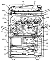
まず、実施形態に係る複写機の基本的な構成について説明する。図1は、実施形態に係る複写機の概略構成図である。この複写機はプリンタ部100、これを載せる給紙装置200、プリンタ部100の上に固定されたスキャナ300などを備えている。また、このスキャナ300の上に固定された自動原稿搬送装置(以下、ADFという)400なども備えている。
Hereinafter, as an image forming apparatus to which the present invention is applied, an embodiment of a tandem type color laser copier (hereinafter, simply referred to as “copier”) in which a plurality of photoconductors are arranged in parallel will be described.
First, the basic configuration of the copying machine according to the embodiment will be described. FIG. 1 is a schematic configuration diagram of a copying machine according to an embodiment. This copier includes a
プリンタ部100は、イエロー(Y)、マゼンタ(M)、シアン(C)、黒(K)の各色の画像を形成するための4つの作像ユニット18Y,18M,18C,18Kを有する画像形成ユニット20を備えている。各符号の末尾に付されたY,M,C,Kという添字は、イエロー、マゼンタ、シアン、黒用の部材であることを示している(以下同様)。
The
作像ユニット18Y,18M,18C,18Kの他には、光書込ユニット21、中間転写ユニット17、二次転写装置22、レジストローラ対49、ベルト定着方式の定着装置25などが配設されている。光書込ユニット21は、光源、ポリゴンミラー、f−θレンズ、反射ミラーなどを有し、画像データに基づいて後述の感光体の表面にレーザー光を照射する。
In addition to the
作像ユニット18Y,18M,18C,18Kは、ドラム状の感光体1、帯電器、現像装置4、ドラムクリーニング装置、除電器などを有している。以下、イエロー用の作像ユニット18Yを例にして説明する。帯電手段たる帯電器によって、感光体1Yの表面は一様帯電される。帯電処理が施された感光体1Yの表面には、光書込ユニット21によって変調及び偏向されたレーザー光が照射される。すると、照射部(露光部)の電位が減衰する。この減衰により、感光体1Yの表面にY用の静電潜像が形成される。形成されたY用の静電潜像は現像手段たる現像装置4Yによって現像されてYトナー像となる。
The
Y用の感光体1Y上に形成されたYトナー像は、後述する中間転写ベルト110に一次転写される。一次転写後の感光体1Yの表面は、ドラムクリーニング装置によって転写残トナーがクリーニングされる。その後、感光体1Yの表面は、除電器によって除電される。そして、帯電器によって一様帯電せしめられて、初期状態に戻る。以上のような一連のプロセスが、他の作像ユニット18M,18C,18Kにおいても同様に行われる。
The Y toner image formed on the photoconductor 1Y for Y is primarily transferred to the
中間転写ユニット17は、中間転写ベルト110やベルトクリーニング装置90などを有している。また、張架ローラ14、駆動ローラ15、二次転写バックアップローラ16、4つの一次転写バイアスローラ62Y,62M,62C,62Kなども有している。中間転写ベルト110は、張架ローラ14を含む複数のローラによってテンション張架されている。そして、ベルト駆動モータによって駆動される駆動ローラ15の回転駆動によって図中時計回り方向に無端移動せしめられる。
The
4つの一次転写バイアスローラ62Y,62M,62C,62Kは、それぞれ中間転写ベルト110の内周面側に接触するように配設され、電源から一次転写バイアスの印加を受ける。また、中間転写ベルト110をその内周面側から感光体1Y,1M,1C,1Kに向けて押圧してY,M,C,K用の一次転写ニップを形成する。各一次転写ニップには、一次転写バイアスの影響により、感光体と一次転写バイアスローラとの間に一次転写電界が形成される。
The four primary
Y用の感光体1Y上に形成されたYトナー像は、この一次転写電界やニップ圧の影響によって中間転写ベルト110上に一次転写される。このYトナー像の上には、M,C,K用の感光体1M,C,K上に形成されたM,C,Kトナー像が順次重ね合わせて一次転写される。この重ね合わせの一次転写により、中間転写ベルト110上には多重トナー像たる4色重ね合わせトナー像(以下、4色トナー像という)が形成される。
The Y toner image formed on the photoconductor 1Y for Y is primarily transferred onto the
中間転写ベルト110上に重ね合わせ転写された4色トナー像は、後述の二次転写ニップで記録体たる記録シートに二次転写される。二次転写ニップ通過後の中間転写ベルト110の表面に残留する転写残トナーは、図中左側の駆動ローラ15との間にベルトを挟み込むベルトクリーニング装置90によってクリーニングされる。
The four-color toner image superimposed and transferred on the
中間転写ユニット17の図中下方には、2本の張架ローラ23によって紙搬送ベルト24を張架している二次転写装置22が配設されている。紙搬送ベルト24は、少なくとも何れか一方の張架ローラ23の回転駆動に伴って、図中反時計回り方向に無端移動せしめられる。2本の張架ローラ23のうち、図中右側に配設された一方のローラは、中間転写ユニット17の二次転写バックアップローラ16との間に、中間転写ベルト110及び紙搬送ベルト24を挟み込んでいる。この挟み込みにより、中間転写ユニット17の中間転写ベルト110と、二次転写装置22の紙搬送ベルト24とが接触する二次転写ニップが形成されている。そして、この一方の張架ローラ23には、トナーと逆極性の二次転写バイアスが電源によって印加される。
A
二次転写バイアスの印加により、二次転写ニップには中間転写ユニット17の中間転写ベルト110上の4色トナー像をベルト側からこの一方の張架ローラ23側に向けて静電移動させる二次転写電界が形成される。後述のレジストローラ対49によって中間転写ベルト110上の4色トナー像に同期するように二次転写ニップに送り込まれた記録シートには、この二次転写電界やニップ圧の影響を受けた4色トナー像が二次転写せしめられる。
By applying the secondary transfer bias, the four-color toner image on the
複写機本体の下部に設けられた給紙装置200には、内部に複数の記録シートを紙束の状態で複数枚重ねて収容可能な給紙カセット44が、鉛直方向に複数重なるように配設されている。それぞれの給紙カセット44は、紙束の一番上の記録シートに給紙ローラ42を押し当てている。そして、給紙ローラ42を回転させることにより、一番上の記録シートを給紙路46に向けて送り出される。
In the
給紙カセット44から送り出された記録シートを受け入れる給紙路46は、複数の搬送ローラ対47と、その路内の末端付近に設けられたレジストローラ対49とを有している。そして、記録シートをレジストローラ対49に向けて搬送する。レジストローラ対49に向けて搬送された記録シートは、レジストローラ対49のローラ間に挟まれる。一方、中間転写ユニット17において、中間転写ベルト110上に形成された4色トナー像は、ベルトの無端移動に伴って上記二次転写ニップに進入する。レジストローラ対49は、ローラ間に挟み込んだ記録シートを二次転写ニップにて4色トナー像に密着させ得るタイミングで送り出す。
The
二次転写ニップでは、中間転写ベルト110上の4色トナー像が記録シートに密着する。そして、記録シート上に二次転写されて、白色の記録シート上でフルカラー画像となる。このようにしてフルカラー画像が形成された記録シートは、紙搬送ベルト24の無端移動に伴って二次転写ニップを出た後、紙搬送ベルト24上から定着装置25に送られる。
In the secondary transfer nip, the four-color toner image on the
定着装置25は、定着ベルト26を2本のローラによって張架しながら無端移動せしめるベルトユニットと、このベルトユニットの一方のローラに向けて押圧される加圧ローラ27とを備えている。これら定着ベルト26と加圧ローラ27とは互いに当接して定着ニップを形成しており、紙搬送ベルト24から受け取った記録シートをここに挟み込む。ベルトユニットにおける2本のローラのうち、加圧ローラ27から押圧される方のローラは、内部に熱源を有しており、これの発熱によって定着ベルト26を加圧する。加圧された定着ベルト26は、定着ニップに挟み込まれた記録シートを加熱する。この加熱やニップ圧の影響により、フルカラー画像が記録シートに定着せしめられる。
The fixing
定着装置25内で定着処理が施された記録シートは、プリンタ筐体の図中左側板の外側に設けたスタック部57上にスタックされるか、もう一方の面にもトナー像を形成するために上述の二次転写ニップに戻されるかする。
The recording sheet that has been fixed in the fixing
原稿のコピーがとられる際には、例えばシート原稿の束がADF400の原稿台30上セットされる。但し、その原稿が本状に閉じられている片綴じ原稿である場合には、コンタクトガラス32上にセットされる。このセットに先立ち、複写機本体に対してADF400が開かれ、スキャナ300のコンタクトガラス32が露出される。この後、閉じられたADF400によって片綴じ原稿が押さえられる。
When a copy of the original is taken, for example, a bundle of sheet originals is set on the
原稿がセットされた後、コピースタートスイッチが押下されると、スキャナ300による原稿読取動作がスタートする。但し、ADF400にシート原稿がセットされた場合には、この原稿読取動作に先立って、ADF400がシート原稿をコンタクトガラス32まで自動移動させる。原稿読取動作では、まず、第1走行体33と第2走行体34とがともに走行を開始し、第1走行体33に設けられた光源から光が発射される。そして、原稿面からの反射光が第2走行体34内に設けられたミラーによって反射せしめられ、結像レンズ35を通過した後、読取センサー36に入射される。読取センサー36は、入射光に基づいて画像情報を構築する。
When the copy start switch is pressed after the document is set, the document scanning operation by the
このような原稿読取動作と並行して、作像ユニット18Y,18M,18C,18K内の各機器や、中間転写ユニット17、二次転写装置22、定着装置25がそれぞれ駆動を開始する。そして、読取センサー36によって構築された画像情報に基づいて、光書込ユニット21が駆動制御されて、各感光体1Y,1M,1C,1K上に、Y,M,C,Kトナー像が形成される。これらトナー像は、中間転写ベルト110上に重ね合わせ転写された4色トナー像となる。
In parallel with such a document reading operation, each device in the
また、原稿読取動作の開始とほぼ同時に、給紙装置200内では給紙動作が開始される。この給紙動作では、給紙ローラ42の1つが選択回転せしめられ、ペーパーバンク43内に多段に収容される給紙カセット44の1つから記録シートが送り出される。送り出された記録シートは、分離ローラ45で1枚ずつ分離されて給紙路46に進入した後、搬送ローラ対47によって二次転写ニップに向けて搬送される。このような給紙カセット44からの給紙に代えて、手差しトレイ51からの給紙が行われる場合もある。この場合、手差し給紙ローラ50が選択回転せしめられて手差しトレイ51上の記録シートを送り出した後、分離ローラ52が記録シートを1枚ずつ分離してプリンタ部100の手差し給紙路53に給紙する。
Further, almost at the same time as the start of the document reading operation, the paper feeding operation is started in the
2色以上のトナーからなる多色画像を形成する場合には、中間転写ベルト110をその上部張架面がほぼ水平になる姿勢で張架して、上部張架面に全ての感光体1Y,1M,1C,1Kを接触させる。これに対し、Kトナーのみからなるモノクロ画像を形成する場合には、姿勢調整機構により、中間転写ベルト110を図中左下に傾けるような姿勢にして、その上部張架面をY,M,C用の感光体1Y,M,Cから離間させる。そして、4つの感光体1Y,1M,1C,1Kのうち、K用の感光体1Kだけを図中反時計回りに回転させて、Kトナー像だけを作像する。この際、Y,M,Cについては、感光体1Y,1M,1Cだけでなく、現像器も駆動を停止させて、感光体や現像剤の不要な消耗を防止する。
When forming a multicolor image consisting of two or more colors of toner, the
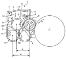
図2は、4つ作像ユニット18Y,M,C,Kのうちの何れか1つにおける現像装置4及び感光体1を示す拡大構成図である。4つの作像ユニット18Y,18M,18C,18Kは、それぞれ扱うトナーの色が異なる点の他がほぼ同様の構成になっているので、同図では「4」の後に付すY,M,C,Kという添字を省略している。
FIG. 2 is an enlarged configuration diagram showing a developing
感光体1は図中矢印G方向に回転しながら、その表面が帯電装置によって帯電せしめられる。帯電した感光体1の表面は光書込ユニット21から照射されたレーザー光によって静電潜像を担持する。この静電潜像に対して現像装置4によってトナーが供給されることで、静電潜像が現像されてトナー像になる。
The surface of the
現像装置4は、図中矢印I方向に回転しながら感光体1の表面の静電潜像にトナーを供給して静電潜像を現像する現像剤担持体としての現像ローラ5を有している。また、現像ローラ5に現像剤を供給しながら図の紙面に直交する方向現像剤を搬送する供給搬送部材としての供給スクリュー8を具備する供給搬送路9を有している。
The developing
供給搬送路9内では、供給スクリュー8の回転駆動により、磁性キャリア及びトナーを含有する現像剤がスクリュー回転軸線方向に搬送される。現像ローラ5は、非磁性パイプからなる中空構造の回転可能な現像スリーブ5aと、これに連れ回らないように内包され且つスリーブ回転方向に並ぶ複数の磁極を具備する磁力発生部たるマグネットローラ5bとを有している。現像スリーブ5aは、その回転に伴って供給搬送路9との対向部を通過する際に、回転不能なマグネットローラ5bの汲み上げ磁極の発する磁力により、供給搬送路9内の現像剤を汲み上げて担持する。これによって現像スリーブ5aの表面上に形成された現像剤の層は、規制部材たる規制ブレード12の先端と現像スリーブ5aの表面との間に形成される規制ギャップを通過する際に、その層厚が所定の厚みに規制される。
In the supply transport path 9, the developer containing the magnetic carrier and toner is transported in the screw rotation axis direction by the rotational drive of the
規制ギャップを通過して所定の厚みに規制された現像剤層は、現像スリーブ5aの回転に伴って、感光体1と対向する現像領域に搬送されて現像に寄与する。その後、現像ローラ5の回転に伴って、回収スクリュー6との対向位置まで搬送される。その対向位置には、現像ローラ5に内包される回転不能なマグネットローラ5bの2つの反発磁極により、反発磁界が形成されている。現像剤層はその反発磁界の作用によって現像スリーブ5aの表面から離脱して回収搬送路7内の回収スクリュー6に回収される。
The developer layer that has passed through the regulation gap and is regulated to a predetermined thickness is conveyed to the developing region facing the
規制ブレード12の近傍であって且つ規制ブレード12よりも現像スリーブ5aの回転方向の上流側には、規制ブレード12によって規制されて規制ブレード12よりも上流側で滞留する現像剤の量を規制する滞留規制部材13が配設されている。この滞留規制部材13は、前述した規制ギャップよりも大きな滞留ギャップを介して、現像スリーブ5aの表面に対向する対向部材である。
In the vicinity of the
供給搬送路9の下方であって回収搬送路7の側方には、攪拌搬送路10が配設されている。攪拌搬送路10内においては、撹拌スクリュー11の回転駆動により、現像剤が供給搬送路9とは逆に図の紙面の直交する方向における奥側から手前側に向けて搬送される。供給搬送路9と攪拌搬送路10とは仕切り部材としての第一仕切り壁133によって仕切られている。第一仕切り壁133の供給搬送路9と攪拌搬送路10とを仕切る箇所は図の紙面に直交する方向の手前側と奥側との両端は開口部となっており、供給搬送路9と攪拌搬送路10とが連通している。
A stirring
供給搬送路9と回収搬送路7とも第一仕切り壁133によって仕切られているが、第一仕切り壁133の供給搬送路9と回収搬送路7とを仕切る箇所には開口部が設けられていない。また、攪拌搬送路10と回収搬送路7との2つの搬送路は仕切り部材としての第二仕切り壁134によって仕切られている。第二仕切り壁134は、図の紙面に直交する方向における手前側が開口部となっており、攪拌搬送路10と回収搬送路7とが連通している。
Both the supply transport path 9 and the
供給スクリュー8、回収スクリュー6及び攪拌スクリュー11は樹脂製もしくは金属製のスクリュー部材からなっている。供給スクリューは2条巻き構造のスクリュー部材であり、回収スクリュー6及び攪拌スクリュー11は1条巻き構造のスクリュー部材である。
The
表面に複数のV溝あるいはサンドブラスト処理による複数の凹部を具備している現像スリーブ5aは、アルミ製又はステンレス製の素管からなる。規制ブレード12と感光体1との間には、規制ギャップが形成されている。
The developing
回収搬送路7に回収された現像剤は、図の紙面の直交する奥側から手前側に搬送され、手前側の端部付近に存在する開口部を通過して攪拌搬送路10に進入する。その直後に、攪拌搬送路10の上側に設けられたトナー補給口から補給されてくる新たなトナーと混合される。回収搬送路7の図中手前側端部まで搬送された現像剤は、第一仕切り壁133における図中手前側の端部に設けられた開口を通って、供給搬送路9内に進入する。
The developer recovered in the
攪拌搬送路10から供給搬送路9に進入した現像剤は、供給スクリュー8の回転駆動に伴って、図の紙面の直交する方向における手前側から奥側に向けて搬送される。その過程で、一部の現像剤が現像ローラ5に汲み上げられる。残りの現像剤は、供給搬送路9における図中奥側の端部まで搬送され、第一仕切り壁133の図中奥側の端部に設けられた開口部を通って攪拌搬送路10に戻される。攪拌搬送路10の底板には、トナー濃度センサーが設けられおり、制御部はトナー濃度センサーから出力に基づいて、必要に応じてトナー補給装置を駆動して現像剤のトナー濃度を回復させる。
The developer that has entered the supply transport path 9 from the stirring
供給搬送路9の現像剤搬送方向の下流端近傍には、現像剤排出口94が設けられており、供給搬送路9内における現像剤の高さレベルが閾値を超えた場合には、現像剤排出口94から現像剤がオーバーフローする。そして、排出搬送スクリュー2aによって現像装置4の外部に排出される。
A
供給搬送路9内では、現像剤が移動する際の勢いや、供給スクリュー8の回転する力によって飛び跳ねることで、現像剤の高さレベルが閾値を超えていないにもかかわらず、現像剤が現像剤排出口94から排出されてしまうことがある。このような排出を防止するために、供給搬送路9の上方にブロック部材3を設け、供給スクリュー8の回転に伴って飛び跳ねようとする現像剤をブロック部材3に当てて供給スクリュー8に戻すようにしている。ブロック部材3は、その底面が供給スクリュー8の形状に沿ったR形状の樹脂製の部材である。供給スクリュー8の形状に沿ったR形状であることにより、供給スクリュー8全体を覆うようにブロック部材3の底面を全体的に供給スクリュー8に近接させることが可能になる。これにより、現像剤の飛び跳ねを確実に阻止することができる。
In the supply transport path 9, the developer develops even though the height level of the developer does not exceed the threshold value by jumping due to the momentum when the developer moves or the rotating force of the
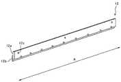
図3は、現像装置4の規制ブレード12を示す斜視図である。規制ブレード12は、板状のブレード本体部12aと、板状の先端磁性板12bとを有している。ステンレス板等からなるブレード本体部12aは、規制ブレード12全体としてある程度の剛性を発揮できるように、比較的厚めの板状に成形された板状部材からなる。薄板状の先端磁性板12bは、規制ブレード12における現像スリーブ5aに対向する先端部を構成するものであり、比較的薄い磁性板からなる。この先端磁性板12bがブレード本体部12aにおけるスリーブ回転方向上流側の面の先端部に固定されている。この固定は、複数のネジによるネジ止めによって行われている。規制ギャップは、0.4〜0.6[mm]に設定されている。また、滞留ギャップは0.9〜1.1[mm]に設定されている。
FIG. 3 is a perspective view showing the
次に、従来の現像装置で発生した不具合について説明する。
図4は、従来の現像装置における現像ローラ5a及びその周囲を示す拡大断面図である。現像ローラ5aのマグネットローラ5bは、回転方向に並ぶ5つ以上の磁極を有しているが、同図では便宜上、汲み上げ磁極5b−1、規制磁極5b−2、及び規制下流磁極5b−3の3つだけを示している。
Next, a defect that has occurred in the conventional developing apparatus will be described.
FIG. 4 is an enlarged cross-sectional view showing the developing
図中時計回り方向に回転する非磁性パイプからなる現像スリーブ5aは、供給スクリー8との対向位置で、規制磁極5b−1の発する磁力により、供給スクリュー8内の現像剤500を自らの方に引き寄せて自らの表面に担持しながら汲み上げる。汲み上げられた現像剤500は、現像スリーブ5aの回転に伴って規制磁極5b−2との対向位置に進入し、規制磁極5b−2の磁力によって穂立ちする。その後、現像スリーブ5aの回転に伴って規制ブレード12との対向位置にくると、穂の先端側の移動が規制されて、現像剤層が所定の厚みになる。規制ブレード12によって現像スリーブ5aとの連れ回りを規制された現像剤500は、規制ブレード12よりもスリーブ回転方向の上流側で滞留する。滞留規制部材13は、自らと現像スリーブ5aとの間における空間の容積を一定量にしていることで、現像剤500の滞留量を規制している。
In the figure, the developing
磁性キャリアの劣化が進行していないときには、現像剤500の流動性がある程度良好である。このため、規制ブレード12よりも上流側に滞留した現像剤500中の磁性キャリア粒子は、現像スリーブ5aに連れ回る現像剤500に擦られながら活発に回転して、やがて現像剤500とともに移動している連れ回りの現像剤500に取り込まれる。そして、最終的には規制ギャップを通過して現像に寄与する。
When the deterioration of the magnetic carrier has not progressed, the fluidity of the
ところが、トナー成分の固着によって磁性キャリアの劣化が進行して現像剤500の流動性が低下してくると、規制ブレード12よりも上流側に滞留する現像剤500の動きが鈍くなってくる。そして、図5に示されるように、個々の磁性キャリア粒子が活発に回転するのではなく、滞留している現像剤500の全体がスリーブ回転方向に動こうとするようになるが、その動きは規制ブレード12の先端磁性板12bの側面によって阻止される。これにより、規制ブレード12よりも上流側には、個々の磁性キャリア粒子の動きが殆ど認められない現像剤500の不動層501が形成される。
However, when the deterioration of the magnetic carrier progresses due to the sticking of the toner component and the fluidity of the
不動層501が形成されると、不動層501と、現像スリーブ501に連れ回っている現像剤500との摺擦によって生じた熱が、不動層501中にこもるようになり、トナーの溶融による不動層501中の現像剤500の劣化が助長される。この助長により、不動層501の厚みが徐々に成長していき、やがて、不動層501が規制ブレード12の先端よりも現像スリーブ5a側に突き出るようになる。この状態では、不動層501が現像スリーブ5aに連れ回っている現像剤の厚みを規制ギャップよりも狭いギャップで規制するようになることから、現像剤の層厚が不足して現像濃度不足を引き起こしてしまう。
When the
次に、実施形態に係る複写機の特徴的な構成について説明する。
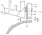
図6は、実施形態に係る複写機の現像装置4における規制ギャップとその周囲とを示す拡大断面図である。同図において、13aは、滞留規制部材13における現像スリーブ5aとの対向面としての対向傾斜面を示している。また、矢印αは、規制ブレード12の先端磁性板12bにおける規制側面(図中左側の面)に直交する面方向であるブレード直交面方向を示している。対向傾斜面13aは、ブレード直交面方向αから傾斜していることで、スリーブ回転方向における上流側から下流側にかけての領域を現像スリーブ5aに徐々に近づける。
Next, a characteristic configuration of the copying machine according to the embodiment will be described.
FIG. 6 is an enlarged cross-sectional view showing a regulation gap and its surroundings in the developing
滞留規制部材13の対向傾斜面13aと、現像スリーブ5aとの間の滞留ギャップG2は、規制ギャップG1よりも大きな値に設定されている。
The retention gap G2 between the facing
図7は、実施形態に係る複写機の現像装置4における規制磁極の磁力と、規制下流磁極の磁力とを説明するための断面図である。同図において、現像スリーブ5aの周囲に描かれている太線は、磁極のスリーブ法線方向の磁力を示している。この現像装置5においては、規制磁極5b−2の磁力の極大点P1を規制ブレード12よりもスリーブ回転方向の上流側に位置させ、且つ、規制下流磁極5b−3の磁力の極大点P2を規制ブレード12よりもスリーブ回転方向の下流側に位置させている。そして、二つの磁力分布の交点である極小点P3を規制ブレード12の先端磁性板12aの先端に対向させている。その極小点P3の位置では、磁力線がスリーブ表面の接線方向に延びている。そして、その接線方向は、現像剤が規制ギャップを通過しようとする方向と同じである。
FIG. 7 is a cross-sectional view for explaining the magnetic force of the regulated magnetic pole and the magnetic force of the regulated downstream magnetic pole in the developing
古くは、規制磁極5b−2の磁力の極大点P1を先端磁性板12aの延長線上に位置させて、先端磁性板12aの位置で現像剤を最も高く穂立ちさせる措置をとることが一般的であった。しかしながら、このようにすると、規制ギャップG1内において、スリーブ表面の接線方向に移動しようとする現像剤をスリーブ表面に引き付けてしまう。そして、劣化の進行によって流動性を低下させた現像剤を規制ギャップG1に良好に通すことが困難になって、現像剤の層厚不足による現像濃度不足を引き起こし易くなることが解ってきた。
In the olden days, it was common to position the maximum point P1 of the magnetic force of the regulating
そこで、実施形態に係る複写機では、図示のように、極小点P2を先端磁性板12bの先端に対向さている。このようにして、規制ギャップG1における磁力線の向きと、現像剤の移動方向とを一致させることで、規制ギャップG1内での現像剤の滞りによる層厚不足の発生を抑えることができる。
Therefore, in the copying machine according to the embodiment, as shown in the drawing, the minimum point P2 faces the tip of the tip
但し、極小点P2を先端磁性板12bの先端に対向させると、図示のように、規制磁極5b−2の法線方向における磁力分布の殆どを、現像剤を滞留させる滞留空間内に位置させることから、不動層をより形成し易くなってしまう。そこで、実施形態に係る複写機では、上述のように、滞留規制部材13の現像スリーブ5aとの対向面をブレード直交面方向αから傾けた対向傾斜面13aにしている。
However, when the minimum point P2 is opposed to the tip of the tip
図8は、実施形態に係る複写機の現像装置4における現像ローラ5a及びその周囲を示す拡大断面図である。実施形態に係る複写機の現像装置4においては、図示のように、規制ブレード12よりもスリーブ回転方向の上流側に滞留する現像剤500が、スリーブの回転に伴って、傾斜している対向傾斜面13aに押し付けられる。
FIG. 8 is an enlarged cross-sectional view showing the developing
図9は、実施形態に係る複写機の現像装置4における滞留現像剤を拡大して示す拡大断面図である。同図において、現像スリーブ5aの回転に伴って、滞留規制部材13の傾斜している対向傾斜面13aに押し付けられた現像剤500は、対向傾斜面13aに沿って矢印Hの方向に進む。その進行方向には、先端磁性板12bの側面ではなく、規制ギャップG1が位置している。つまり、対向傾斜面13aに押し付けられた現像剤500は、規制ギャップG1に向けて案内される。これにより、規制ギャップG1に進入し易くなる。このように、規制ギャップG1に対して比較的近い位置では、図中矢印Iのように現像スリー5aに連れ回る現像剤500の上に、対向傾斜面13aに沿って現像ギャップG1に向けて案内される(矢印H)現像剤の流れが発生することで、不動層の形成が抑えられる。規制ギャプG1から比較的離れた位置では、対向傾斜面13aに沿って矢印H方向に進む現像剤500に追従して動こうとする後続の現像剤500に対して、更なる後続の現像剤が摺擦する。この摺擦により、前述した更なる後続の現像剤が図中矢印J、K、Lで示されるように、図中反時計回り方向に渦運動をする。この渦運動により、規制ギャップG1から比較的離れた位置においても、現像剤が活発に動くことで、不動層の形成が抑えられる。
FIG. 9 is an enlarged cross-sectional view showing an enlarged retention developer in the developing
このように、規制ブレード12よりもスリーブ回転方向の上流側における規制ギャップに比較的近い位置の現像剤が規制ギャップに向けてスムーズに移動したり、規制ギャップから比較的離れた位置の現像剤が渦運動をしたりすることで不動層の形成が抑えられる。
In this way, the developer at a position relatively close to the regulation gap on the upstream side in the sleeve rotation direction with respect to the
なお、図6において、規制ギャップG1とこれよりも大きな滞留ギャップG1との差L1を大きく設定し過ぎると、たとえ対向傾斜面13aを図示のようにブレード直交面方向αから傾斜させていても、不動層の発生を抑えることが困難になる。
In FIG. 6, if the difference L1 between the regulation gap G1 and the retention gap G1 larger than this is set too large, even if the facing
本発明者らは、実施形態に係る複写機と同様の構成の複写試験機を用意した。また、滞留規制部材13として、互いに異なる厚みで形成されていることで滞留ギャップG2の値を互いに異ならせる4種類のものを用意した。そして、それぞれの滞留規制部材13について、汲み上げ低下率[%]を調べる実験を行った。具体的には、K用の現像装置4Kに、新品のK現像剤をセットした状態で、黒ベタ画像を所定枚数プリントした後、現像装置4Kを複写試験機から取り外した。そして、現像装置4Kの現像スリーブ5aを1回転させながら、ケーシングからのスリーブ露出箇所に当接させたスクレーパーによって現像スリーブ5a表面上の現像剤を掻き取って、その重さを新品現像剤汲み上げ量として測定した。次に、現像装置4K内の現像剤を劣化進行によって流動性を低下させたものに入れ替えた後、同様にして、現像スリーブ5aを一回転させる間に現像スリーブ5a上の現像剤を掻き取って、その重さを劣化現像剤汲み上げ量として測定した。そして、新品現像剤汲み上げ量から劣化現像剤汲み上げ量を差し引いた値における新品現像剤汲み上げ量に対する割合を汲み上げ低下率[%]として求めた。
The present inventors prepared a copying test machine having the same configuration as the copying machine according to the embodiment. In addition, four types of
流動性が良好な新品現像剤では、不動層が形成されないことから、規制ブレード12による規制位置を通過した後の現像スリーブ5aの表面に所望の厚みの現像剤層が形成される。これに対し、流動性が低下している劣化現像剤では、差L1が比較的大きくなると、不動層が形成されることがある。不動層が形成されると、不動層が規制ギャップG1よりも狭いギャップで現像剤の層厚を規制するようになることから、現像剤の層厚が通常よりも低下する。この低下率を示すものが上述した汲み上げ低下率である。
Since the immovable layer is not formed in the new developer having good fluidity, a developer layer having a desired thickness is formed on the surface of the developing
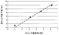
本発明者らが行った実験における汲み上げ低下率[%]とギャップ差倍率[倍]との関係を図10にグラフとして示す。ギャップ差倍率[倍]は、差L1について規制ギャップG1の何倍にあたるのかを示す数値である。現像剤の層厚が通常よりも低下する、即ち、現像剤汲み上げ量が通常よりも少なくなると、現像装置4の現像能力が低下するので好ましくない。許容できる汲み上げ低下率の上限は2[%]程度である。図示のように、ギャップ差倍率を1.75[倍]以下に留めれば、汲み上げ低下率を2[%]以下にすることが可能である。つまり、差L1を規制ギャップG1の1.75倍以下に留めれば、不動層の発生を有効に抑え得ることが実験によって確認された。
The relationship between the pumping reduction rate [%] and the gap difference magnification [times] in the experiments conducted by the present inventors is shown as a graph in FIG. The gap difference magnification [times] is a numerical value indicating how many times the difference L1 corresponds to the regulation gap G1. If the layer thickness of the developer is lower than usual, that is, if the amount of pumped developer is smaller than usual, the developing capacity of the developing
そこで、実施形態に係る複写機では、差L1を規制ギャップG1の1.75倍以下に設定している。 Therefore, in the copying machine according to the embodiment, the difference L1 is set to 1.75 times or less of the regulation gap G1.
規制ブレード12の薄板状部材たる先端磁性板12bは磁性材料からなるのに対し、板状部材たるブレード本体部12aは非磁性材料からなる。そして、先端磁性板12bは、ブレード本体部12aよりもかなり薄厚になっている。かかる構成では、規制ブレード12の先端において、磁力を実際の規制に携わる先端磁性板12に集中させることで、磁力を分散させることによる現像剤の層厚の不安定化を回避することができる。また、薄厚の磁性板だけで構成するのではなく、ブレード本体部12aを設けることで、規制ブレード12全体に必要な剛性を発揮させることができる。
The tip
先端磁性板12bについては、ブレード本体部12aにおけるスリーブ回転方向の下流側の面ではなく、図示のように、上流側の面に固定している。下流側の面に固定すると、先端磁性坂12bのブレード本体部12aから突出している箇所で規制した現像剤をブレード本体部12aの厚み分の領域に滞留させてしまうことから、不動層の発生を助長してしまう。上流側の面に固定することで、その助長を回避することができる。
The tip
先端磁性板12bは、打ち抜き加工によって製造されたものである。かかる先端磁性板12の先端においては、打ち抜き方向の上流側のエッジがダレ面となって微小面取り構造になるのに対し、打ち抜き方向の下流側のエッジがバリ面となって微小な突起であるバリを具備する構造になる。このバリにより、先端磁性板12bによって規制した現像剤を下方から支えてしまうと、現像剤の滞りを助長してしまう。
The tip
そこで、実施形態に係る複写機では、スリーブ回転方向の上流側のエッジをダレ面側のエッジにする姿勢で先端磁性板12bをブレード本体部12aに固定している。かかる構成では、規制ブレード12によって規制した現像剤を先端のバリによって下方から支えることによる現像剤の滞りを回避することができる。
Therefore, in the copying machine according to the embodiment, the tip
図8に示されるように、アルミからなる滞留規制部材13は、中空の構造になっていて、その内壁には、放熱を促すための複数のリブ13bが設けられている。滞留規制部材13の中空には、ファンによって気流が送り込まれる。これにより、滞留規制部材13をヒートシンクとして機能させている。
As shown in FIG. 8, the
上述したように、実施形態に係る複写機では、規制ブレード12によって記載された現像剤が二つの渦運動を形成して活発に動くが、そのときに磁性キャリア粒子同士が擦られて発生した熱は、滞留規制部材13に良好に吸熱される。これにより、滞留中の現像剤の発熱を抑えることで、不動層の発生をより確実に抑えることができる。
As described above, in the copying machine according to the embodiment, the developer described by the
以上に説明したものは一例であり、次の態様毎に特有の効果を奏する。
[態様A]
態様Aは、無端移動する表面に担持した現像剤(例えば現像剤500)により、画像形成装置(例えば複写機)の潜像担持体(例えば感光体1)上の潜像を現像する現像剤担持体(例えば現像ローラ5)と、前記現像剤担持体の表面に対して規制ギャップ(例えば規制ギャップG1)を介して対向するように配設され、前記現像剤担持体の表面上における現像剤の層厚を規制する規制部材(例えば規制ブレード12)と、前記規制部材の近傍であって且つ前記規制部材よりも現像剤担持体の表面移動方向の上流側で前記現像剤担持体に対向する対向面を具備する対向部材(例えば滞留規制部材13)とを有する現像装置(例えば現像装置4)において、前記対向面を、前記規制部材の面に直交する面方向から傾斜させて前記対向面の前記表面移動方向における上流側から下流側にかけての領域を前記現像剤担持体に徐々に近づけた対向傾斜面(例えば対向傾斜面面13a)とし、且つ、前記対向傾斜面と前記現像剤担持体との間のギャップ(例えば滞留ギャップG2)と、前記ギャップよりも狭い前記規制ギャップとの差(例えば差L1)を、前記規制ギャップの1.75倍以下にしたことを特徴とするものである。
What has been described above is an example, and has a unique effect in each of the following aspects.
[Aspect A]
In aspect A, a developer-supported developer that develops a latent image on a latent image-bearing body (for example, photoconductor 1) of an image forming apparatus (for example, a copying machine) by a developer (for example, a developing agent 500) supported on an endlessly moving surface. A body (for example, a developing roller 5) and a developing agent on the surface of the developing agent carrier are arranged so as to face each other with a regulating gap (for example, a regulating gap G1). Opposing a regulating member (for example, a regulating blade 12) that regulates the layer thickness and facing the developing agent carrier in the vicinity of the regulating member and upstream of the restricting member in the surface movement direction of the developer carrier. In a developing device (for example, developing device 4) having a facing member having a surface (for example, a retention regulating member 13), the facing surface is inclined from a plane direction orthogonal to the surface of the regulating member to be said to be the facing surface. The region from the upstream side to the downstream side in the surface moving direction is a facing inclined surface (for example, the facing
態様Aにおいては、現像剤担持体の表面移動に伴って、対向部材の傾斜している対向傾斜面に押し付けられた現像剤のうち、規制ギャップに対して比較的近い位置にある現像剤は、現像剤担持体の表面移動に追従するように対向傾斜面に沿って進む。その進行方向には、規制部材の先端エッジや規制ギャップが位置している。即ち、規制ギャップの比較的近くで対向部材の対向傾斜面に押し付けられた現像剤は、規制部材の先端エッジや規制ギャップに向けて案内されて、やがて規制ギャップ内に進入する。このように、規制ギャップの比較的近くでは、対向傾斜面に沿って規制ギャップに向けて良好に移動する現像剤の流れができることで、不動層の発生が抑えられる。また、規制ギャプから比較的離れた位置では、規制ギャップに向けて良好に移動する現像剤に追従して移動しようとする後続の現像剤に対して、更なる後続の現像剤が摺擦しながら渦運動をする。この渦運動により、規制ギャップから比較的離れた位置においても、不動層の発生が抑えられる。 In the aspect A, among the developing agents pressed against the inclined facing inclined surfaces of the opposing members as the surface of the developing agent carrier moves, the developing agent located at a position relatively close to the regulation gap is used. It proceeds along the facing inclined surface so as to follow the surface movement of the developer carrier. The tip edge of the regulating member and the regulating gap are located in the traveling direction. That is, the developer pressed against the facing inclined surface of the facing member relatively close to the regulation gap is guided toward the tip edge of the regulating member and the regulation gap, and eventually enters the regulation gap. In this way, relatively close to the regulation gap, the flow of the developer that moves satisfactorily toward the regulation gap along the facing inclined surface is formed, so that the generation of the immovable layer is suppressed. Further, at a position relatively distant from the regulation gap, a further subsequent developer rubs against a subsequent developer that attempts to follow and move the developer that moves well toward the regulation gap. Make a vortex motion. Due to this vortex motion, the generation of the immovable layer is suppressed even at a position relatively far from the regulation gap.
[態様B]
態様Bは、態様Aにおいて、現像剤として、トナーと磁性キャリアとを含有するものを用い、前記現像剤担持体として、回転する自らの表面に現像剤を担持する中空構造の現像スリーブ(例えば現像スリーブ5a)、及びこれに連れ回らないように内包され且つスリーブ回転方向に沿って配設された複数の磁極を具備する磁力発生部(例えばマグネットローラ5b)を有するものを用い、前記複数の磁極のうち、前記規制部材によって層厚が規制される現像剤を前記現像スリーブの表面上に拘束するための規制磁極(例えば規制磁極5b−2)のスリーブ周囲における法線方向の磁力の極大点(例えば極大点P1)を前記規制部材よりもスリーブ回転方向の上流側に位置させ、且つ、前記規制磁極に対してスリーブ回転方向の下流側で隣り合っている規制下流磁極(例えば規制下流磁極5b−3)のスリーブ周囲における法線方向の磁力の極大点(例えば極大点P2)を前記規制部材よりもスリーブ回転方向の下流側に位置させたことを特徴とするものである。かかる構成では、規制磁極の磁力の極大点を規制部材の先端に対向させる構成に比べて、規制ギャップ内における現像剤の滞りを抑えることができる。
[Aspect B]
Aspect B uses a developer containing a toner and a magnetic carrier as the developer in Aspect A, and as the developer carrier, a hollow-structured developing sleeve (for example, developing) that carries the developer on its own rotating surface. A
[態様C]
態様Cは、態様Bにおいて、前記規制磁極及び前記規制下流磁極のそれぞれにおける法線方向の磁力の極小点(例えば極小点P3)を前記基線部材の先端との対向位置に位置させたことを特徴とするものである。かかる構成では、規制ギャップ内における磁力線の向きと、規制ギャップ内における現像剤の移動方向とを一致させることで、現像剤をスムーズに規制ギャップに通して、規制ギャップ内での現像剤の滞りを抑えることができる。
[Aspect C]
Aspect C is characterized in that, in aspect B, the minimum point (for example, the minimum point P3) of the magnetic force in the normal direction at each of the regulated magnetic pole and the regulated downstream magnetic pole is positioned at a position facing the tip of the baseline member. Is to be. In such a configuration, by matching the direction of the magnetic field lines in the regulation gap with the moving direction of the developer in the regulation gap, the developer can be smoothly passed through the regulation gap to prevent the developer from staying in the regulation gap. It can be suppressed.
[態様D]
態様Dは、態様A〜Cの何れかにおいて、非磁性の板状部材(例えばブレード本体部12a)と、これの先端よりも自らの先端を前記現像剤担持体に向けて突き出させる姿勢で前記板状部材に固定され、且つ前記板状部材よりも薄厚の磁性の薄板状部材(例えば先端磁性板12b)とで、前記規制部材を構成し、前記薄板状部材を前記板状部材における前記表面移動方向の上流側の面に固定したことを特徴とするものである。かかる構成では、規制部材の先端にて、磁力を磁性材料からなる薄厚の薄板状部材先端に集中させることで、磁力を分散させることによる現像剤の層厚の不安定化を回避することができる。また、肉厚の板状部材の厚みの領域に現像剤を滞留させてしまうことを回避することもできる。
[Aspect D]
In aspect D, in any of aspects A to C, the non-magnetic plate-shaped member (for example, the blade
[態様E]
態様Eは、態様Dにおいて、前記薄板状部材の先端における前記表面移動方向の上流側のエッジを打ち抜き加工におけるダレ面側のエッジにする姿勢で前記薄板状部材を配設したことを特徴とするものである。かかる構成では、規制部材によって規制した現像剤を薄板状部材のバリで下側から支えることによる現像剤の滞りの助長を回避することができる。
[Aspect E]
Aspect E is characterized in that, in aspect D, the thin plate-shaped member is arranged in a posture in which the edge on the upstream side in the surface moving direction at the tip of the thin plate-shaped member is set to the edge on the sagging surface side in the punching process. It is a thing. In such a configuration, it is possible to avoid the promotion of stagnation of the developer by supporting the developer regulated by the regulating member from below with burrs of the thin plate-shaped member.
[態様F]
態様Fは、態様A〜Eの何れかにおいて、前記対向部材における前記対向傾斜面とは異なる箇所に、放熱用の複数のリブ(例えばリブ13b)を設けたことを特徴とするものである。かかる構成では、規制部材によって規制された現像剤同士が擦れ合うことによって発生した熱を対向部材によって吸熱することで、現像剤の発熱による不動層の発生の助長を回避することができる。
[Aspect F]
Aspect F is characterized in that, in any of aspects A to E, a plurality of ribs (for example,
[態様G]
態様Gは、態様Fにおいて、前記対向部材としてアルミ製のものを用いたことを特徴とするものである。かかる構成では、熱伝導率の良いアルミ製の対向部材によって現像剤の熱を良好に吸熱することができる。
[Aspect G]
Aspect G is characterized in that, in Aspect F, an aluminum member is used as the facing member. In such a configuration, the heat of the developer can be satisfactorily absorbed by the aluminum facing member having good thermal conductivity.
[態様H]
態様Hは、潜像担持体と、前記潜像担持体に担持される潜像を現像する現像装置とを備える画像形成装置において、前記現像装置として、態様A〜Gの何れかの現像装置を用いたことを特徴とするものである。
[Aspect H]
Aspect H is an image forming apparatus including a latent image carrier and a developing apparatus for developing a latent image supported on the latent image carrier. As the developing apparatus, any developing apparatus of aspects A to G is used. It is characterized by being used.
1:感光体(潜像担持体)
4:現像装置
5:現像ローラ
5a:現像スリーブ
5b:マグネットローラ(磁力発生部)
5b−2:規制磁極
5b−3:規制下流磁極
12:規制ブレード(規制部材)
12a:ブレード本体部(板状部材)
12b:先端磁性板(薄板状部材)
13:滞留規制部材(対向部材)
13a:対向傾斜面
13b:リブ
500:現像剤
P1:規制磁極の磁力の極大点
P2:規制下流磁極の磁力の極大点
P3:極小点
G1:規制ギャップ
G2:滞留ギャップ
L1:差
1: Photoreceptor (latent image carrier)
4: Developing device 5: Developing
5b-2: Regulatory
12a: Blade body (plate-shaped member)
12b: Tip magnetic plate (thin plate-shaped member)
13: Retention control member (opposing member)
13a: Facing
Claims (7)
前記現像剤担持体の表面に対して規制ギャップを介して対向するように配設され、前記現像剤担持体の表面上における現像剤の層厚を規制する規制部材と、
前記規制部材の近傍であって且つ前記規制部材よりも現像剤担持体の表面移動方向の上流側で前記現像剤担持体に対向する対向面を具備する対向部材とを有する現像装置において、
前記現像剤担持体として、回転する自らの表面に現像剤を担持する中空構造の現像スリーブ、及びこれに連れ回らないように内包され且つスリーブ回転方向に沿って配設された複数の磁極を具備する磁力発生部を有するものを用い、
前記規制部材は、非磁性の板状部材と、前記板状部材の前記表面移動方向における上流側に固定された前記板状部材よりも薄厚の磁性の薄板状部材と、で構成され、
前記規制部材の前記現像剤担持体側の先端エッジは前記薄板状部材で構成され、
前記対向面を、前記規制部材の面に直交する面方向から傾斜させて前記対向面の前記表面移動方向における上流側から下流側にかけての領域を前記現像剤担持体に徐々に近づけた対向傾斜面とし、
前記対向傾斜面の延長線上に前記規制ギャップが位置し、
且つ、前記対向傾斜面と前記現像剤担持体との間のギャップと、前記ギャップよりも狭い前記規制ギャップとの差を、前記規制ギャップの1.75倍以下にしたことを特徴とする現像装置。 A developer carrier that develops a latent image on a latent image carrier of an image forming apparatus with a developer containing toner and a magnetic carrier supported on an endlessly moving surface.
A regulatory member that is disposed so as to face the surface of the developer carrier via a regulation gap and regulates the layer thickness of the developer on the surface of the developer carrier.
In a developing apparatus having a facing member having a facing surface facing the developer carrier in the vicinity of the regulating member and upstream of the regulating member in the surface movement direction of the developer carrier.
The developing agent carrier includes a developing sleeve having a hollow structure that supports the developing agent on its own rotating surface, and a plurality of magnetic poles that are included so as not to rotate with the developing agent and are arranged along the sleeve rotation direction. Using a device that has a magnetic force generating part
The regulating member is composed of a non-magnetic plate-shaped member and a magnetic thin plate-shaped member fixed to the upstream side of the plate-shaped member in the surface movement direction and having a thickness thinner than that of the plate-shaped member.
The tip edge of the regulating member on the developer carrier side is composed of the thin plate-shaped member.
The facing surface is inclined from a plane direction orthogonal to the surface of the regulating member, and the region of the facing surface from the upstream side to the downstream side in the surface movement direction is gradually brought closer to the developer carrier. age,
The regulation gap is located on the extension of the facing inclined surface,
The developing apparatus is characterized in that the difference between the gap between the facing inclined surface and the developer carrier and the regulation gap narrower than the gap is 1.75 times or less the regulation gap. ..
前記複数の磁極のうち、前記規制部材によって層厚が規制される現像剤を前記現像スリーブの表面上に拘束するための規制磁極のスリーブ周囲における法線方向の磁力の極大点を前記規制部材よりもスリーブ回転方向の上流側に位置させ、
且つ、前記規制磁極に対してスリーブ回転方向の下流側で隣り合っている規制下流磁極のスリーブ周囲における法線方向の磁力の極大点を前記規制部材よりもスリーブ回転方向の下流側に位置させたことを特徴とする現像装置。 In the developing apparatus of claim 1,
Of the plurality of magnetic poles, the maximum point of the magnetic force in the normal direction around the sleeve of the regulating magnetic pole for restraining the developer whose layer thickness is regulated by the regulating member on the surface of the developing sleeve is set from the regulating member. Also located upstream in the sleeve rotation direction,
Further, the maximum point of the magnetic force in the normal direction around the sleeve of the regulated downstream magnetic pole adjacent to the regulated magnetic pole on the downstream side in the sleeve rotation direction is positioned on the downstream side in the sleeve rotation direction with respect to the restricting member. A developing device characterized by that.
前記規制磁極及び前記規制下流磁極のそれぞれにおける法線方向の磁力の極小点を前記規制部材の先端との対向位置に位置させたことを特徴とする現像装置。 In the developing apparatus of claim 2,
A developing apparatus characterized in that a minimum point of magnetic force in the normal direction at each of the regulated magnetic pole and the regulated downstream magnetic pole is positioned at a position facing the tip of the regulating member.
前記薄板状部材の先端における前記表面移動方向の上流側のエッジを打ち抜き加工におけるダレ面側のエッジにする姿勢で前記薄板状部材を配設したことを特徴とする現像装置。 In the developing apparatus according to any one of claims 1 to 3,
A developing apparatus characterized in that the thin plate-shaped member is arranged in such a posture that the edge on the upstream side in the surface moving direction at the tip of the thin plate-shaped member is the edge on the sagging surface side in punching.
前記対向部材における前記対向傾斜面とは異なる箇所に、放熱用の複数のリブを設けたことを特徴とする現像装置。 In the developing apparatus according to any one of claims 1 to 4,
A developing apparatus characterized in that a plurality of ribs for heat dissipation are provided in a portion of the facing member different from the facing inclined surface.
前記対向部材としてアルミ製のものを用いたことを特徴とする現像装置。 In the developing apparatus of claim 5,
A developing device characterized in that an aluminum material is used as the facing member.
前記現像装置として、請求項1乃至6の何れかの現像装置を用いたことを特徴とする画像形成装置。 In an image forming apparatus including a latent image carrier and a developing apparatus for developing a latent image supported on the latent image carrier.
An image forming apparatus according to any one of claims 1 to 6, wherein the developing apparatus is used as the developing apparatus.
Priority Applications (2)
| Application Number | Priority Date | Filing Date | Title |
|---|---|---|---|
| JP2016111565A JP6792811B2 (en) | 2016-06-03 | 2016-06-03 | Developing equipment and image forming equipment |
| US15/604,235 US10007209B2 (en) | 2016-06-03 | 2017-05-24 | Developing device and image forming apparatus incorporating same that reduce low-flow regions of toner within the developing device |
Applications Claiming Priority (1)
| Application Number | Priority Date | Filing Date | Title |
|---|---|---|---|
| JP2016111565A JP6792811B2 (en) | 2016-06-03 | 2016-06-03 | Developing equipment and image forming equipment |
Related Child Applications (1)
| Application Number | Title | Priority Date | Filing Date |
|---|---|---|---|
| JP2020125700A Division JP6997971B2 (en) | 2020-07-22 | 2020-07-22 | Developing equipment and image forming equipment |
Publications (3)
| Publication Number | Publication Date |
|---|---|
| JP2017219574A JP2017219574A (en) | 2017-12-14 |
| JP2017219574A5 JP2017219574A5 (en) | 2019-03-22 |
| JP6792811B2 true JP6792811B2 (en) | 2020-12-02 |
Family
ID=60482239
Family Applications (1)
| Application Number | Title | Priority Date | Filing Date |
|---|---|---|---|
| JP2016111565A Active JP6792811B2 (en) | 2016-06-03 | 2016-06-03 | Developing equipment and image forming equipment |
Country Status (2)
| Country | Link |
|---|---|
| US (1) | US10007209B2 (en) |
| JP (1) | JP6792811B2 (en) |
Families Citing this family (9)
| Publication number | Priority date | Publication date | Assignee | Title |
|---|---|---|---|---|
| JP6953833B2 (en) * | 2017-06-27 | 2021-10-27 | コニカミノルタ株式会社 | Develop equipment and image forming equipment |
| JP7075624B2 (en) | 2018-09-28 | 2022-05-26 | 株式会社リコー | Developing equipment, process cartridges, and image forming equipment |
| JP7148890B2 (en) | 2018-10-10 | 2022-10-06 | 株式会社リコー | image forming device |
| JP7211042B2 (en) | 2018-11-30 | 2023-01-24 | 株式会社リコー | Developer storage container, developing device and image forming apparatus |
| JP7344466B2 (en) | 2019-09-17 | 2023-09-14 | 株式会社リコー | Developing device, process cartridge, and image forming device |
| JP7495657B2 (en) | 2020-05-21 | 2024-06-05 | 株式会社リコー | Developing device and image forming apparatus |
| JP7465447B2 (en) | 2020-05-25 | 2024-04-11 | 株式会社リコー | DEVELOPER CONTAINING DEVICE, DEVELOPING DEVICE, PROCESS CARTRIDGE, AND IMAGE FORMING APPARATUS |
| US11494602B2 (en) | 2020-09-15 | 2022-11-08 | Ricoh Company, Ltd. | Image forming apparatus |
| JP2024048409A (en) * | 2022-09-28 | 2024-04-09 | シャープ株式会社 | Image forming apparatus |
Family Cites Families (34)
| Publication number | Priority date | Publication date | Assignee | Title |
|---|---|---|---|---|
| US4887131A (en) * | 1987-03-16 | 1989-12-12 | Canon Kabushiki Kaisha | Developing apparatus using magnetic particles and toner particles |
| JP2001215794A (en) * | 1994-01-14 | 2001-08-10 | Kyocera Mita Corp | Image forming machine |
| JP3959222B2 (en) | 1999-05-06 | 2007-08-15 | 株式会社リコー | Developing device and image forming apparatus |
| JP2003122128A (en) * | 2001-10-12 | 2003-04-25 | Ricoh Co Ltd | Developing device and image forming device |
| JP3659355B2 (en) * | 2003-09-09 | 2005-06-15 | シャープ株式会社 | Developing device and image forming apparatus |
| JP3989422B2 (en) | 2003-09-19 | 2007-10-10 | 株式会社リコー | Developing device, image forming apparatus, and process cartridge |
| JP4451668B2 (en) | 2004-01-27 | 2010-04-14 | 株式会社リコー | Developing device, process cartridge, and image forming apparatus |
| JP2006301330A (en) * | 2005-04-21 | 2006-11-02 | Ricoh Co Ltd | Developing device |
| JP5095171B2 (en) * | 2006-01-27 | 2012-12-12 | 株式会社リコー | Developing device and image forming apparatus |
| JP2008129109A (en) * | 2006-11-17 | 2008-06-05 | Murata Mach Ltd | Image forming apparatus |
| JP5052906B2 (en) * | 2007-01-31 | 2012-10-17 | 京セラドキュメントソリューションズ株式会社 | Developing device and image forming apparatus |
| KR20080106693A (en) * | 2007-06-04 | 2008-12-09 | 삼성전자주식회사 | Developing device and image forming apparatus having the same |
| JP2010266674A (en) * | 2009-05-14 | 2010-11-25 | Sharp Corp | Developing device and image forming apparatus using the same |
| JP2011048105A (en) * | 2009-08-26 | 2011-03-10 | Sharp Corp | Developing device and image forming apparatus having the same |
| JP2011112935A (en) | 2009-11-27 | 2011-06-09 | Ricoh Co Ltd | Developing device, process cartridge, and image forming apparatus |
| JP5515866B2 (en) | 2010-03-04 | 2014-06-11 | 株式会社リコー | Developing device, process cartridge, and image forming apparatus |
| JP5482543B2 (en) * | 2010-07-28 | 2014-05-07 | コニカミノルタ株式会社 | Two-component developing device |
| KR101777346B1 (en) * | 2010-08-11 | 2017-09-27 | 에스프린팅솔루션 주식회사 | Developing device and image forming apparatus using the same |
| JP2012047901A (en) | 2010-08-25 | 2012-03-08 | Ricoh Co Ltd | Developing device and image forming apparatus using same |
| JP5769067B2 (en) | 2010-08-27 | 2015-08-26 | 株式会社リコー | Developing device and image forming apparatus having the same |
| JP5598311B2 (en) | 2010-12-22 | 2014-10-01 | 株式会社リコー | Developing device, process cartridge, and image forming apparatus |
| JP2012155008A (en) * | 2011-01-24 | 2012-08-16 | Ricoh Co Ltd | Developing device, image forming device and developing method |
| JP5773245B2 (en) | 2011-02-28 | 2015-09-02 | 株式会社リコー | Developing device, image forming apparatus, and process cartridge |
| JP2012230203A (en) * | 2011-04-25 | 2012-11-22 | Ricoh Co Ltd | Development device and image forming apparatus |
| JP5839263B2 (en) | 2011-08-01 | 2016-01-06 | 株式会社リコー | Developing device, process cartridge, and image forming apparatus |
| KR101896052B1 (en) * | 2012-04-19 | 2018-09-06 | 에이치피프린팅코리아 주식회사 | developing device and electrophotographic image forming apparatus using the same |
| JP2013246276A (en) | 2012-05-25 | 2013-12-09 | Ricoh Co Ltd | Developing device and image forming apparatus including the same |
| JP2014089386A (en) * | 2012-10-31 | 2014-05-15 | Ricoh Co Ltd | Developer regulating member, developing device, and image forming apparatus |
| JP2015004773A (en) | 2013-06-20 | 2015-01-08 | 株式会社リコー | Developing apparatus, process cartridge, and image forming apparatus |
| JP6183695B2 (en) | 2013-07-18 | 2017-08-23 | 株式会社リコー | DEVELOPING DEVICE, IMAGE FORMING DEVICE EQUIPPED WITH THE SAME |
| KR101546831B1 (en) * | 2013-07-31 | 2015-08-24 | 삼성전자주식회사 | developing device and electrophotographic image forming apparatus using the same |
| JP6440016B2 (en) | 2014-09-04 | 2018-12-19 | 株式会社リコー | Developing device, process cartridge, and image forming apparatus |
| JP2016126197A (en) | 2015-01-05 | 2016-07-11 | 株式会社リコー | Developing device and image forming apparatus |
| US9817335B2 (en) | 2015-10-21 | 2017-11-14 | Ricoh Company, Ltd. | Powder amount detector, powder supply device, and image forming apparatus incorporating same |
-
2016
- 2016-06-03 JP JP2016111565A patent/JP6792811B2/en active Active
-
2017
- 2017-05-24 US US15/604,235 patent/US10007209B2/en active Active
Also Published As
| Publication number | Publication date |
|---|---|
| US10007209B2 (en) | 2018-06-26 |
| JP2017219574A (en) | 2017-12-14 |
| US20170351195A1 (en) | 2017-12-07 |
Similar Documents
| Publication | Publication Date | Title |
|---|---|---|
| JP6792811B2 (en) | Developing equipment and image forming equipment | |
| JP4820689B2 (en) | Developing device, process cartridge, and image forming apparatus | |
| JP5152628B2 (en) | Developing device, image forming apparatus | |
| JP4672509B2 (en) | Developing device and image forming apparatus | |
| JP2008046240A (en) | Developing device, process cartridge and image forming apparatus | |
| JP2007193289A (en) | Developing device and image forming apparatus | |
| JP5039352B2 (en) | Developing device, process cartridge, and image forming apparatus | |
| JP6440016B2 (en) | Developing device, process cartridge, and image forming apparatus | |
| JP2008249835A (en) | Developing device and image forming apparatus | |
| JP5277587B2 (en) | Image forming apparatus | |
| JP6440017B2 (en) | Developing device and image forming apparatus | |
| JP2012230203A (en) | Development device and image forming apparatus | |
| JP5240557B2 (en) | Developing device, image forming apparatus, and process cartridge | |
| JP2008203814A (en) | Developing device and image forming apparatus | |
| JP5442186B2 (en) | Developing device, image forming apparatus, and process cartridge | |
| JP5811437B2 (en) | Developing device and image forming apparatus using the same | |
| JP2009063710A (en) | Developing unit and image forming device | |
| JP5158473B2 (en) | Developing device and image forming apparatus | |
| JP6997971B2 (en) | Developing equipment and image forming equipment | |
| JP5252329B2 (en) | Developing device, image forming apparatus | |
| JP5033534B2 (en) | Developing device and image forming apparatus | |
| JP2009134167A (en) | Developer control member, developing device, image forming apparatus, process cartridge and image forming method | |
| JP7073818B2 (en) | Develop device, process cartridge unit and image forming device | |
| JP4971054B2 (en) | Developing device, process cartridge, and image forming apparatus | |
| JP2010217328A (en) | Developing device, image-forming device, and process cartridge |
Legal Events
| Date | Code | Title | Description |
|---|---|---|---|
| A521 | Written amendment |
Free format text: JAPANESE INTERMEDIATE CODE: A523 Effective date: 20190208 |
|
| A621 | Written request for application examination |
Free format text: JAPANESE INTERMEDIATE CODE: A621 Effective date: 20190227 |
|
| A977 | Report on retrieval |
Free format text: JAPANESE INTERMEDIATE CODE: A971007 Effective date: 20191107 |
|
| A131 | Notification of reasons for refusal |
Free format text: JAPANESE INTERMEDIATE CODE: A131 Effective date: 20191115 |
|
| A521 | Written amendment |
Free format text: JAPANESE INTERMEDIATE CODE: A523 Effective date: 20200114 |
|
| A02 | Decision of refusal |
Free format text: JAPANESE INTERMEDIATE CODE: A02 Effective date: 20200424 |
|
| A521 | Written amendment |
Free format text: JAPANESE INTERMEDIATE CODE: A523 Effective date: 20200727 |
|
| C60 | Trial request (containing other claim documents, opposition documents) |
Free format text: JAPANESE INTERMEDIATE CODE: C60 Effective date: 20200727 |
|
| A911 | Transfer to examiner for re-examination before appeal (zenchi) |
Free format text: JAPANESE INTERMEDIATE CODE: A911 Effective date: 20200812 |
|
| C21 | Notice of transfer of a case for reconsideration by examiners before appeal proceedings |
Free format text: JAPANESE INTERMEDIATE CODE: C21 Effective date: 20200821 |
|
| TRDD | Decision of grant or rejection written | ||
| A01 | Written decision to grant a patent or to grant a registration (utility model) |
Free format text: JAPANESE INTERMEDIATE CODE: A01 Effective date: 20201009 |
|
| A61 | First payment of annual fees (during grant procedure) |
Free format text: JAPANESE INTERMEDIATE CODE: A61 Effective date: 20201022 |
|
| R151 | Written notification of patent or utility model registration |
Ref document number: 6792811 Country of ref document: JP Free format text: JAPANESE INTERMEDIATE CODE: R151 |