JP5037253B2 - Developing device, image forming apparatus - Google Patents

Developing device, image forming apparatus Download PDF

Info

Publication number
JP5037253B2
JP5037253B2 JP2007196352A JP2007196352A JP5037253B2 JP 5037253 B2 JP5037253 B2 JP 5037253B2 JP 2007196352 A JP2007196352 A JP 2007196352A JP 2007196352 A JP2007196352 A JP 2007196352A JP 5037253 B2 JP5037253 B2 JP 5037253B2
Authority
JP
Japan
Prior art keywords
developer
supply
conveyance path
developing device
conveyance
Prior art date
Legal status (The legal status is an assumption and is not a legal conclusion. Google has not performed a legal analysis and makes no representation as to the accuracy of the status listed.)
Expired - Fee Related
Application number
JP2007196352A
Other languages
Japanese (ja)
Other versions
JP2008203814A (en
JP2008203814A5 (en
Inventor
清典 津田
純一 寺井
桂子 松本
健太郎 冨田
皓一 宇都宮
Current Assignee (The listed assignees may be inaccurate. Google has not performed a legal analysis and makes no representation or warranty as to the accuracy of the list.)
Ricoh Co Ltd
Original Assignee
Ricoh Co Ltd
Priority date (The priority date is an assumption and is not a legal conclusion. Google has not performed a legal analysis and makes no representation as to the accuracy of the date listed.)
Filing date
Publication date
Application filed by Ricoh Co Ltd filed Critical Ricoh Co Ltd
Priority to JP2007196352A priority Critical patent/JP5037253B2/en
Priority to US12/019,984 priority patent/US8295737B2/en
Publication of JP2008203814A publication Critical patent/JP2008203814A/en
Publication of JP2008203814A5 publication Critical patent/JP2008203814A5/ja
Application granted granted Critical
Publication of JP5037253B2 publication Critical patent/JP5037253B2/en
Expired - Fee Related legal-status Critical Current
Anticipated expiration legal-status Critical

Links

Images

Description

本発明は、複写機、ファクシミリ、プリンタ等に用いられる現像装置並びにこれを用いた画像形成装置に関するものである。   The present invention relates to a developing device used for a copying machine, a facsimile, a printer, and the like, and an image forming apparatus using the developing device.

従来から、トナーと磁性キャリアとを含む二成分の現像剤を用いた現像装置を備える画像形成装置が広く用いられている。この種の画像形成装置として、現像に伴ってトナーを消費する現像装置内の現像剤に対して、必要に応じてトナー収容器からトナーを補給することで、現像剤のトナー濃度を所定範囲内に維持するものがある。かかる構成では、現像剤内のキャリアは殆ど消費されず繰り返し使用されるため、画像を出力するにしたがってキャリアの表層のコート層が磨耗したり逆にコート層にトナー樹脂や添加剤が付着したりする。これにより、キャリアのトナーを帯電させる能力が徐々に低下して、キャリアが劣化した状態となる。キャリアの劣化が進行するとトナーの帯電量が低下し、地肌部汚れやトナー飛散などを引き起こすため、この種の画像形成装置では定期的にサービスマンがユーザーを訪問してキャリアの交換を行っていた。このために、メンテナンス費用がかかり画像形成の単価が高くなってしまっていた。   Conventionally, an image forming apparatus including a developing device using a two-component developer including toner and a magnetic carrier has been widely used. As an image forming apparatus of this type, the toner density of the developer is kept within a predetermined range by supplying toner from the toner container as necessary to the developer in the developing apparatus that consumes toner with development. There is something to keep in. In such a configuration, the carrier in the developer is hardly consumed and is repeatedly used. As the image is output, the coat layer on the surface of the carrier wears out, and conversely, toner resin and additives adhere to the coat layer. To do. As a result, the ability of the carrier to charge the toner gradually decreases, and the carrier is in a deteriorated state. As the deterioration of the carrier progresses, the charge amount of the toner decreases, causing background stains and toner scattering. Therefore, in this type of image forming apparatus, a service person visits the user regularly to replace the carrier. . For this reason, maintenance costs are incurred, and the unit price for image formation is high.

特許文献1には、キャリアとトナーとを混合したプレミックス現像剤を現像装置内の現像剤に補給してトナー濃度の回復を図りながら、増加量分の現像剤を現像装置から排出させる現像装置が記載されている。かかる構成では、現像剤の排出によって古くなったキャリアを少しずつ現像装置内から排出しつつ、プレミックス現像剤中の新しいキャリアを現像装置内の現像剤に補給する。そして、このような排出と補給とによって現像剤中のキャリアを少しずつ新たなものに交換していくことで、キャリアの交換作業を省くことができる。
また、特許文献1の現像装置では、現像剤を現像ローラに供給しながら現像ローラの軸方向に現像剤を搬送する供給搬送路の所定の高さに現像剤を装置外に排出する現像剤排出手段としての現像剤排出口を備えている。この現像装置では、プレミックス現像剤が供給され、現像装置内の現像剤量が増加すると、供給搬送路内の現像剤の嵩が高くなる。このとき、現像剤排出口を設けた位置で、現像剤排出口の高さまで到達した現像剤は現像剤排出口から現像装置外部へ排出される。
Patent Document 1 discloses a developing device that discharges an increased amount of developer from the developing device while replenishing the developer in the developing device with a premix developer in which a carrier and toner are mixed to recover the toner concentration. Is described. In such a configuration, a new carrier in the premix developer is replenished to the developer in the developing device while the carrier that has become old due to the discharge of the developer is gradually discharged from the developing device. Then, the carrier replacement work can be omitted by replacing the carrier in the developer gradually with a new one by such discharge and replenishment.
Further, in the developing device disclosed in Patent Document 1, the developer is discharged to the outside of the device at a predetermined height of a supply conveyance path for conveying the developer in the axial direction of the developing roller while supplying the developer to the developing roller. As a means, a developer discharge port is provided. In this developing device, when the premix developer is supplied and the amount of developer in the developing device increases, the bulk of the developer in the supply conveyance path increases. At this time, the developer reaching the height of the developer discharge port at the position where the developer discharge port is provided is discharged from the developer discharge port to the outside of the developing device.

特開2005−292511号公報JP 2005-292511 A

しかしながら、特許文献1の現像装置では、供給搬送路内で現像ローラに現像剤を供給する現像剤供給領域の途中に現像剤排出口を設けている。
供給搬送路内を搬送される現像剤は移動する勢いや、現像剤に搬送力を与える搬送部材が搬送スクリュの場合はその回転する力などによって飛び跳ねて、現像剤排出口から排出されることがある。現像剤が飛び跳ねて排出される場合、供給搬送路内を搬送される現像剤が適正な量の状態や、適正な量を下回る状態であっても、飛び跳ねた現像剤が排出されるおそれがある。これは、現像装置内の現像剤量が増加していないにもかかわらず現像剤が排出される状態である。そして、現像剤が適正な量以下の状態であるにもかかわらず現像剤排出口から現像剤が排出されると、現像装置内の現像剤量が必要量を下回り、潜像担持体への現像剤の供給が不安定になるおそれがあった。潜像担持体への現像剤の供給が不安定になると、画像抜けなどの異常画像が発生するおそれがある。
このような問題は、二成分現像剤を用いた現像装置に限るものではなく、現像剤補給手段によって現像剤の補給が成され、現像装置内の現像剤の増加量分を現像剤排出手段によって排出する構成を備えた現像装置であれば一成分現像剤を用いる現像装置であっても生じ得る問題である。
However, in the developing device of Patent Document 1, a developer discharge port is provided in the middle of a developer supply region for supplying the developer to the developing roller in the supply conveyance path.
The developer transported in the supply transport path jumps by the momentum to move, and when the transport member that imparts transport force to the developer is a transport screw, it can be ejected and discharged from the developer discharge port. is there. When the developer jumps and is discharged, even if the developer transported in the supply transport path is in an appropriate amount state or less than the appropriate amount, the jumped developer may be discharged. . This is a state in which the developer is discharged even though the amount of developer in the developing device has not increased. If the developer is discharged from the developer discharge port even though the developer is in an appropriate amount or less, the amount of developer in the developing device falls below the required amount, and the development on the latent image carrier is performed. The supply of the agent might become unstable. If the supply of the developer to the latent image carrier becomes unstable, abnormal images such as missing images may occur.
Such a problem is not limited to the developing device using the two-component developer, but the developer is replenished by the developer replenishing means, and the amount of the developer in the developing device is increased by the developer discharging means. This is a problem that may occur even in a developing device that uses a one-component developer as long as the developing device has a configuration for discharging.

本発明は、以上の問題に鑑みなされたものであり、その目的とするところは、飛び跳ねた現像剤が排出されることを防止し、現像装置内の現像剤量が増加していないにも関わらず現像剤が排出されることを防止することによって、潜像担持体に安定した現像剤の供給を行うことができる現像装置、並びにこの現像装置を備えた画像形成装置を提供することである。   The present invention has been made in view of the above problems, and the object of the present invention is to prevent the splashed developer from being discharged and to prevent the developer amount in the developing device from increasing. Accordingly, it is an object of the present invention to provide a developing device capable of stably supplying the developer to the latent image carrier by preventing the developer from being discharged, and an image forming apparatus including the developing device.

上記目的を達成するために、請求項1の発明は、現像剤を表面上に担持して回転し、潜像担持体と対向する箇所で該潜像担持体の表面の潜像にトナーを供給して現像する現像剤担持体と、装置内に現像剤を補給する現像剤補給手段と、該現像剤担持体に現像剤を供給しながら該現像剤担持体の軸線方向に沿って現像剤を搬送する供給搬送部材を備えた供給搬送路と、該供給搬送路の搬送方向下流側に到達した現像剤を該供給搬送路の搬送方向上流側に搬送する循環搬送部材を備えた循環搬送路とを有する現像装置において、該供給搬送路の搬送方向下流側の現像剤の嵩が所定の高さを越えた場合に該供給搬送路の搬送方向下流側の現像剤の一部を排出する現像剤排出手段を有し、該供給搬送路の現像剤搬送方向下流部に、該供給搬送部材とは逆方向の搬送力を発生させる逆搬送部材を備え、該供給搬送部材と該逆搬送部材との境界部に、該供給搬送部材の搬送方向に垂直で、且つ、その法線方向が該供給搬送部材の搬送方向と反対方向となり、現像剤の搬送方向への移動を妨げる壁面を備えることを特徴とするものである。
また、請求項2の発明は、請求項1の現像装置において、上記現像剤排出手段は、上記供給搬送路の搬送方向下流側で仕切り壁を挟んで該供給搬送路と隣り合うように配置され、該供給搬送路から排出される現像剤を搬送する排出搬送路と、該排該仕切り壁の所定の高さに該排出搬送路と該供給搬送路とを連通するように設けられた開口である現像剤排出口とを有し、該現像剤排出口の高さまで到達した現像剤を該現像剤排出口から該排出搬送路へ排出することを特徴とするものである。
また、請求項の発明は、請求項の現像装置において、上記供給搬送路と上記循環搬送路とは供給循環仕切り壁を挟んで隣り合うように配置され、該供給搬送路の搬送方向下流側の該供給循環仕切り壁に供給搬送路と該循環搬送路とを連通する開口部として供給循環連通口を設け、該供給搬送路の搬送方向下流側に到達した現像剤が、該供給循環連通口を通って、該循環搬送路へ移動可能に構成されていることを特徴とするものである。
また、請求項の発明は、請求項の現像装置において、上記現像剤排出口は上記供給搬送路の現像剤搬送方向について、上記供給循環連通口と同じ位置にあることを特徴とするものである。
また、請求項の発明は、請求項またはの現像装置において、上記現像剤排出口は上記供給循環連通口よりも上方に配置されていることを特徴とするものである。
また、請求項の発明は、請求項1、2、3、4またはの現像装置において、上記循環搬送部材は、上記供給搬送路の搬送方向下流端に到達した現像剤を該供給搬送路の搬送方向上流端に搬送し、上記現像剤排出手段は、該供給搬送路の搬送方向下流端近傍の現像剤の嵩が所定の高さを越えた場合に該供給搬送路の搬送方向下流端近傍の現像剤の一部を排出することを特徴とするものである。
また、請求項の発明は、請求項1、2、3、4、5またはの現像装置において、上記供給搬送部材及び上記逆搬送部材は、回転軸と該回転軸に螺旋状に設けられた羽部とを備え、回転することにより該回転軸方向に現像剤を搬送するスクリュ状の供給スクリュ及び逆スクリュであり、該供給スクリュよりも該逆スクリュのスクリュピッチを短くしたことを特徴とするものである。
また、請求項の発明は、請求項1、2、3、4、5、6またはの現像装置において、上記供給搬送部材及び上記逆搬送部材は、回転軸と該回転軸に螺旋状に設けられた羽部とを備え、回転することにより該回転軸方向に現像剤を搬送するスクリュ状の供給スクリュ及び逆スクリュであり、該供給スクリュよりも該逆スクリュの羽部の外径を小さくしたことを特徴とするものである。
また、請求項の発明は、請求項1、2、3、4、5、6、7またはの現像装置において、上記現像剤排出手段は通過した現像剤が排出される現像剤排出口を供給搬送路に備え、上記壁面の上端は該現像剤排出口の下端よりも上方であることを特徴とするものである。
また、請求項10の発明は、請求項1、2、3、4、5、6、7、8またはの現像装置において、上記現像剤排出手段は通過した現像剤が排出される現像剤排出口を供給搬送路に備え、上記現像剤排出口の上記供給搬送路の搬送方向下流端である排出口下流端縁部の該供給搬送路の搬送方向についての位置と、上記壁面の該供給搬送路の搬送方向についての位置とが一致することを特徴とするものである。
また、請求項11の発明は、請求項1、2、3、4、5、6、7、8、9または10の現像装置において、上記現像剤排出手段は通過した現像剤が排出される現像剤排出口を供給搬送路に備え、上記供給搬送部材は、回転軸と該回転軸に螺旋状に設けられた羽部とを備え、回転することにより該回転軸方向に現像剤を搬送するスクリュ状の供給スクリュであり、該現像剤排出口の下端は、該供給スクリュの羽部の上端よりも上方であることを特徴とするものである。
また、請求項12の発明は、請求項1、2、3、4、5、6、7、8、9、10または11の現像装置において、現像剤として磁性キャリアとトナーとからなる成分現像剤を備え、上記潜像担持体と対向する箇所を通過後の上記現像剤担持体上から回収された現像剤を該現像剤担持体の軸線方向に沿って、且つ、上記供給搬送部材と同方向に搬送する回収搬送部材を備えた回収搬送路を有し、上記循環搬送路は、現像に用いられずに該供給搬送路の搬送方向の最下流側まで搬送された現像剤と、該回収搬送路の搬送方向の最下流側まで搬送された現像剤との供給を受け、該現像剤担持体の軸線方向に沿って、且つ、現像剤を攪拌しながら該供給搬送部材とは逆方向に搬送する上記循環搬送部材としての攪拌搬送部材を備え、攪拌後の現像剤を該供給搬送路に供給する攪拌搬送路であり、上記現像剤補給手段は該攪拌搬送路に現像剤を補給することを特徴とするものである。
また、請求項13の発明は、少なくとも潜像担持体と、該潜像担持体表面を帯電させるための帯電手段と、該潜像担持体上に静電潜像を形成するための潜像形成手段と、該静電潜像を現像してトナー像化するための現像手段とを有する画像形成装置において、該現像手段として、請求項1、2、3、4、5、6、7、8、9、10、11または12に記載の現像装置を用いることを特徴とするものである。
また、請求項14の発明は、現像剤を表面上に担持して回転し、潜像担持体と対向する箇所で該潜像担持体の表面の潜像にトナーを供給して現像する現像剤担持体と、装置内に現像剤を補給する現像剤補給手段と、該現像剤担持体に現像剤を供給しながら該現像剤担持体の軸線方向に沿って現像剤を搬送する供給搬送部材を備えた供給搬送路と、該供給搬送路の搬送方向下流側に到達した現像剤を該供給搬送路の搬送方向上流側に搬送する循環搬送部材を備えた循環搬送路とを有する現像装置において、該供給搬送路と該循環搬送路とを含む現像剤搬送路中の現像剤の一部を該現像剤搬送路の外部に排出する現像剤排出口と、該現像剤搬送路中を通過する現像剤の量を規制する現像剤搬送量規制手段とを備え、該現像剤搬送量規制手段によって規制され、滞留した現像剤の量が所定量を越えた場合に該現像剤排出口から現像剤が排出されるように、該現像剤排出口を配置することを特徴とするものである。
また、請求項15の発明は、請求項14の現像装置において、上記循環搬送部材は、上記供給搬送路の搬送方向下流端に到達した現像剤を該供給搬送路の搬送方向上流端に搬送することを特徴とするものである。
In order to achieve the above object, the invention according to claim 1 is characterized in that the developer is carried on the surface and rotated, and the toner is supplied to the latent image on the surface of the latent image carrier at a position facing the latent image carrier. A developer carrier for developing the developer, a developer replenishing means for replenishing the developer in the apparatus, and a developer along the axial direction of the developer carrier while supplying the developer to the developer carrier. A supply conveyance path provided with a supply conveyance member for conveyance; a circulation conveyance path provided with a circulation conveyance member for conveying the developer that has reached the downstream side in the conveyance direction of the supply conveyance path to the upstream side in the conveyance direction of the supply conveyance path; A developer that discharges a part of the developer on the downstream side in the transport direction of the supply transport path when the bulk of the developer on the downstream side in the transport direction of the supply transport path exceeds a predetermined height. have a discharging means, the developer conveying direction downstream portion of the supply conveyance path, and the supply conveyance member A reverse conveying member that generates a conveying force in the direction, and is perpendicular to the conveying direction of the supply conveying member at the boundary between the supply conveying member and the reverse conveying member, and the normal direction is the supply conveying member And a wall surface that prevents the developer from moving in the transport direction .
Further, the invention of claim 2, in the developing apparatus according to claim 1, upper Symbol developer discharging means, arranged adjacent to each other and the supply conveyance path across the partition wall in the conveyance direction downstream side of the supply conveyance path A discharge conveyance path that conveys the developer discharged from the supply conveyance path, and an opening that communicates the discharge conveyance path and the supply conveyance path at a predetermined height of the discharge partition wall. A developer discharge port, and the developer reaching the height of the developer discharge port is discharged from the developer discharge port to the discharge conveyance path.
According to a third aspect of the present invention, in the developing device of the second aspect , the supply conveyance path and the circulation conveyance path are disposed adjacent to each other with a supply circulation partition wall interposed therebetween, and the supply conveyance path is downstream in the conveyance direction. The supply circulation partition wall is provided with a supply circulation communication port as an opening that communicates the supply conveyance path and the circulation conveyance path, and the developer that has reached the downstream side in the conveyance direction of the supply conveyance path is It is configured to be movable to the circulation conveyance path through the mouth.
According to a fourth aspect of the present invention, in the developing device of the third aspect , the developer discharge port is located at the same position as the supply circulation communication port in the developer transport direction of the supply transport path. It is.
According to a fifth aspect of the present invention, in the developing device according to the third or fourth aspect , the developer discharge port is disposed above the supply circulation communication port.
The invention of claim 6 is the developing device according to claim 1, 2, 3, 4 or 5, the circulating conveying member, the supply developer reaching the downstream end in the conveyance direction of the supply conveyance path The developer discharging means transports to the upstream end in the transport direction of the transport path, and the developer discharge means transports the developer in the transport direction of the supply transport path when the volume of the developer near the downstream end in the transport direction of the supply transport path exceeds a predetermined height. A part of the developer near the downstream end is discharged.
Further, an invention according to claim 7, claim 1, 2, 3, 4, in the developing device 5 or 6, upper Symbol supply transport member and the opposite conveying member is helically rotating shaft and said rotary shaft A screw-like supply screw and a reverse screw that convey the developer in the direction of the rotation axis by rotating, and the screw pitch of the reverse screw is made shorter than that of the supply screw. It is characterized by.
According to an eighth aspect of the present invention, in the developing device according to the first, second, third , fourth, fifth, sixth, or seventh aspect , the supply conveyance member and the reverse conveyance member are spirally formed on the rotation shaft and the rotation shaft. A screw-like supply screw and a reverse screw that convey the developer in the direction of the rotation axis by rotating, and the outer diameter of the wing portion of the reverse screw is smaller than that of the supply screw. It is characterized by that.
According to a ninth aspect of the present invention, in the developing device of the first, second, third , fourth, fifth , sixth, seventh or eighth aspect , the developer discharging means has a developer discharge port through which the developer passed therethrough is discharged. provided in the supply path, the upper end of the wall is characterized in that the lower end of the developer discharge port is upward.
The tenth aspect of the present invention is the developing device according to the first, second, third , fourth, fifth , sixth, seventh, eighth or ninth aspect , wherein the developer discharging means discharges the developer discharged therethrough. an outlet to the supply conveyance path, the position of the conveyance direction of the supply conveyance path of the outlet downstream end edge a downstream end in the conveyance direction of the supply conveyance path of the developer discharge port, on Kikabe surface of the The position of the supply conveyance path in the conveyance direction is the same.
According to an eleventh aspect of the present invention, in the developing device according to the first, second, third , fourth, fifth , sixth, seventh , eighth, ninth or tenth development, the developer discharging means discharges the developer that has passed through A screw discharge port is provided in the supply conveyance path, and the supply conveyance member includes a rotation shaft and a wing portion spirally provided on the rotation shaft, and rotates to screw the developer in the rotation axis direction. The lower end of the developer discharge port is above the upper end of the wing portion of the supply screw.
The invention of claim 12, in the developing apparatus according to claim 1,2,3,4,5,6,7,8,9,1 0 or 11, comprising a magnetic carrier and a toner as a developer A two- component developer is provided, and the developer recovered from the developer carrier after passing through a position facing the latent image carrier is supplied along the axial direction of the developer carrier and is supplied and conveyed. A recovery transport path having a recovery transport member that transports in the same direction as the member, and the circulation transport path is not used for development, and the developer transported to the most downstream side in the transport direction of the supply transport path The supply transport member receives supply with the developer transported to the most downstream side in the transport direction of the recovery transport path, and agitates the developer along the axial direction of the developer carrier. A developer after stirring, provided with a stirring transport member as the circulation transport member transported in the reverse direction Is supplied to the supply and conveyance path, and the developer replenishing means supplies the developer to the agitation and conveyance path.
The invention of claim 13 provides at least a latent image carrier, charging means for charging the surface of the latent image carrier, and formation of a latent image for forming an electrostatic latent image on the latent image carrier. And a developing unit for developing the electrostatic latent image into a toner image, wherein the developing unit is defined as claim 1, 2, 3, 4, 5, 6, 7, 8 , 9, 10 was 1 or is characterized in the use of the developing apparatus according to 12.
According to a fourteenth aspect of the present invention, there is provided a developer that rotates by supporting a developer on the surface, supplying toner to the latent image on the surface of the latent image carrier, and developing the developer at a location facing the latent image carrier. A carrier, a developer replenishing means for replenishing the developer in the apparatus, and a supply conveying member that conveys the developer along the axial direction of the developer carrier while supplying the developer to the developer carrier. A developing device having a supply conveyance path and a circulation conveyance path provided with a circulation conveyance member that conveys the developer that has reached the downstream side in the conveyance direction of the supply conveyance path to the upstream side in the conveyance direction of the supply conveyance path; A developer discharge port for discharging a part of the developer in the developer conveyance path including the supply conveyance path and the circulation conveyance path to the outside of the developer conveyance path , and development passing through the developer conveyance path Developer transport amount regulating means for regulating the amount of developer, and the developer transport amount regulating means. Is restricted, the amount of retained the developer is characterized in that the developer from the developer discharge port to be discharged, arranging the developer discharge port when it exceeds a predetermined amount.
The invention of claim 15, in the developing apparatus of claim 14, the circulating conveying member conveys the developer reaching the downstream end in the conveyance direction of the supply conveyance path in the conveyance direction upstream end of the supply conveyance path It is characterized by this.

上記請求項1乃至1の現像装置においては、現像剤排出手段が、供給搬送路の搬送方向下流の現像剤の嵩が所定の高さを越えた場合にその一部を排出するものであるので、供給搬送路の搬送方向下流に、所定の高さを越えない程度の現像剤が存在する状態で現像装置内の現像量が安定した状態となる。
現像装置内に現像剤補給手段によって現像剤が供給されて現像装置内の現像剤量が増加すると、供給搬送路から循環搬送路に受け渡される現像剤量よりも供給搬送路を搬送されその搬送方向下流に到達する現像剤量の方が多くなり、供給搬送路の搬送方向下流に滞留する現像剤の量が増加し嵩が増す。従って、滞留する現像剤が所定の高さを越した場合に、その嵩が所定の高さとなるように滞留する現像剤の一部を現像剤排出手段が排出される。ここで、滞留する現像剤は現像剤が常に移動している箇所の現像剤よりも飛び跳ねにくいので、滞留した箇所の現像剤の嵩は現像装置内の現像剤量の増減に合わせて適正に変化する。よって、現像装置内の現像剤量の必要量を確保することができる。
また、上記請求項14及び15の現像装置においては、現像剤排出口が現像剤搬送量規制手段で規制された現像剤が、所定量を超えた場合にその一部を排出するものであるで、現像剤搬送量規制手段の近傍では所定量を超えない程度の現像剤が存在する状態で現像装置内の現像剤量が安定した状態となる。
現像装置内に現像剤補給手段によって現像剤が供給されて現像装置内の現像剤量が増加すると、現像剤搬送量規制手段によって規制される位置を通過する現像剤量よりもこの規制される位置に到達する現像剤量の方が多くなり、現像剤搬送量規制手段で滞留する現像剤の量が増加する。従って、滞留する現像剤が所定量を超えた場合に、その現像剤量が所定量となるように滞留する現像剤の一部を現像剤排出口から排出する。ここで、滞留する現像剤は現像剤が常に移動している箇所の現像剤よりも飛び跳ねにくいので、滞留した箇所の現像剤量は現像装置内の現像剤量の増減に合わせて適正に変化する。よって、現像装置内の現像剤量の必要量を確保することができる。
Those in the developing apparatus of the above claims 1 to 1 3, the developer discharging means, for discharging a part of the case where the bulk of the downstream side of the developer supply conveyance path exceeds a predetermined height Therefore, the developing amount in the developing device is stabilized in a state where there is a developer that does not exceed the predetermined height on the downstream side in the conveying direction of the supply conveying path.
When the developer is supplied into the developing device by the developer replenishing means and the amount of the developer in the developing device increases, the developer is transported through the supply transport path more than the developer amount delivered from the supply transport path to the circulation transport path. is higher in the amount of developer reaches a downstream side, the amount is increased the bulk of the developer staying in the conveying direction downstream side of the supply conveyance path is increased. Therefore, when the staying developer exceeds a predetermined height, the developer discharge means discharges a part of the staying developer so that the bulk becomes a predetermined height. Here, the stagnant developer is less likely to jump than the developer where the developer is constantly moving, so the bulk of the developer at the stagnant location changes appropriately according to the increase or decrease in the amount of developer in the developing device. To do. Therefore, a necessary amount of developer in the developing device can be ensured.
In the developing device according to the fourteenth and fifteenth aspects, a part of the developer whose developer discharge port is regulated by the developer transport amount regulating means is discharged when it exceeds a predetermined amount . Thus, in the vicinity of the developer transport amount regulating means , the developer amount in the developing device becomes stable in a state where the developer does not exceed the predetermined amount.
When the developer is supplied into the developing device by the developer replenishing means and the amount of the developer in the developing device increases, this regulated position is more than the amount of developer passing through the position regulated by the developer transport amount regulating means. The amount of the developer that reaches is increased, and the amount of the developer staying in the developer transport amount regulating means is increased. Therefore, when the staying developer exceeds a predetermined amount, a part of the staying developer is discharged from the developer discharge port so that the developer amount becomes a predetermined amount. Here, the staying developer is less likely to jump than the developer where the developer is constantly moving, so that the amount of developer at the staying location appropriately changes according to the increase or decrease in the amount of developer in the developing device. . Therefore, a necessary amount of developer in the developing device can be ensured.

請求項1乃至13の発明によれば、現像剤が飛び跳ねにくい現像剤が滞留する箇所である供給搬送路の搬送方向下流の現像剤を排出することにより、飛び跳ねた現像剤が排出されることを防止し、現像装置内の現像剤量が増加していないにも関わらず現像剤が排出されることを防止することことができる。このため、現像装置内の現像剤量として必要量を確保することができ、現像剤担持体から潜像担持体に安定した現像剤の供給を行うことができるという優れた効果がある。
また、請求項14及び15の発明によれば、現像剤搬送量規制手段によって規制されて滞留し、飛び跳ねにくくなった現像剤を排出することにより、飛び跳ねた現像剤が排出されることを防止し、現像装置内の現像剤量が増加していないにも関わらず現像剤が排出されることを防止することことができる。このため、現像装置内の現像剤量として必要量を確保することができ、現像剤担持体から潜像担持体に安定した現像剤の供給を行うことができるという優れた効果がある。
According to the first to thirteenth aspects of the present invention, the developer that has jumped off is discharged by discharging the developer on the downstream side in the transport direction of the supply transport path, where the developer is unlikely to jump. It is possible to prevent the developer from being discharged even though the amount of the developer in the developing device has not increased. For this reason, a necessary amount can be ensured as the amount of developer in the developing device, and there is an excellent effect that the developer can be stably supplied from the developer carrier to the latent image carrier.
Further, according to the inventions of claims 14 and 15 , by discharging the developer that has been restricted and retained by the developer transport amount regulating means and has become difficult to jump, it is possible to prevent the jumped developer from being discharged. The developer can be prevented from being discharged even though the amount of the developer in the developing device has not increased. For this reason, a necessary amount can be ensured as the amount of developer in the developing device, and there is an excellent effect that the developer can be stably supplied from the developer carrier to the latent image carrier.

以下、本発明を適用した画像形成装置として、複数の感光体が並行配設されたタンデム型のカラーレーザー複写機(以下、単に「複写機」という)の一実施形態について説明する。
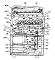
図1は、本実施形態に係る複写機の概略構成図である。この複写機はプリンタ部100、これを載せる給紙装置200、プリンタ部100の上に固定されたスキャナ300などを備えている。また、このスキャナ300の上に固定された原稿自動搬送装置400なども備えている。
Hereinafter, as an image forming apparatus to which the present invention is applied, an embodiment of a tandem type color laser copying machine (hereinafter simply referred to as “copying machine”) in which a plurality of photoconductors are arranged in parallel will be described.
FIG. 1 is a schematic configuration diagram of a copying machine according to the present embodiment. The copier includes a printer unit 100, a paper feeding device 200 on which the printer unit 100 is placed, a scanner 300 fixed on the printer unit 100, and the like. An automatic document feeder 400 fixed on the scanner 300 is also provided.

プリンタ部100は、イエロー(Y)、マゼンダ(M)、シアン(C)、黒(K)の各色の画像を形成するための4組のプロセスカートリッジ18Y,M,C,Kからなる画像形成ユニット20を備えている。各符号の数字の後に付されたY,M,C,Kは、イエロー、シアン、マゼンダ、ブラック用の部材であることを示している(以下同様)。プロセスカートリッジ18Y,M,C,Kの他には、光書込ユニット21、中間転写ユニット17、二次転写装置22、レジストローラ対49、ベルト定着方式の定着装置25などが配設されている。   The printer unit 100 includes an image forming unit including four sets of process cartridges 18Y, 18M, 18C, and 18K for forming images of each color of yellow (Y), magenta (M), cyan (C), and black (K). 20 is provided. Y, M, C, and K attached to the numbers of the respective symbols indicate members for yellow, cyan, magenta, and black (the same applies hereinafter). In addition to the process cartridges 18Y, 18M, 18C, and 18K, an optical writing unit 21, an intermediate transfer unit 17, a secondary transfer device 22, a resist roller pair 49, a belt fixing type fixing device 25, and the like are disposed. .

光書込ユニット21は、図示しない光源、ポリゴンミラー、f−θレンズ、反射ミラーなどを有し、画像データに基づいて後述の感光体の表面にレーザ光を照射する。   The optical writing unit 21 includes a light source (not shown), a polygon mirror, an f-θ lens, a reflection mirror, and the like, and irradiates the surface of a photoreceptor to be described later with laser light based on image data.

プロセスカートリッジ18Y,M,C,Kは、ドラム状の感光体1、帯電器、現像装置4、ドラムクリーニング装置、除電器などを有している。   The process cartridges 18Y, 18M, 18C, and 18K include a drum-shaped photosensitive member 1, a charger, a developing device 4, a drum cleaning device, a static eliminator, and the like.

以下、イエロー用のプロセスカートリッジ18について説明する。
帯電手段たる帯電器によって、感光体1Yの表面は一様帯電される。帯電処理が施された感光体1Yの表面には、光書込ユニット21によって変調及び偏向されたレーザ光が照射される。すると、照射部(露光部)の電位が減衰する。この減衰により、感光体1Y表面にY用の静電潜像が形成される。形成されたY用の静電潜像は現像手段たる現像装置4Yによって現像されてYトナー像となる。
Y用の感光体1Y上に形成されたYトナー像は、後述の中間転写ベルト110に一次転写される。一次転写後の感光体1Yの表面は、ドラムクリーニング装置によって転写残トナーがクリーニングされる。
Y用のプロセスカートリッジ18Yにおいて、ドラムクリーニング装置によってクリーニングされた感光体1Yは、除電器によって除電される。そして、帯電器によって一様帯電せしめられて、初期状態に戻る。以上のような一連のプロセスは、他のプロセスカートリッジ18M,C,Kについても同様である。
Hereinafter, the yellow process cartridge 18 will be described.
The surface of the photoreceptor 1Y is uniformly charged by a charger as charging means. The surface of the photoreceptor 1 </ b> Y that has been subjected to charging processing is irradiated with laser light that has been modulated and deflected by the optical writing unit 21. Then, the potential of the irradiation part (exposure part) is attenuated. By this attenuation, an electrostatic latent image for Y is formed on the surface of the photoreceptor 1Y. The formed electrostatic latent image for Y is developed by the developing device 4Y as developing means to become a Y toner image.
The Y toner image formed on the Y photoconductor 1Y is primarily transferred to an intermediate transfer belt 110 described later. The surface of the photoreceptor 1Y after the primary transfer is cleaned of the transfer residual toner by a drum cleaning device.
In the Y process cartridge 18Y, the photoconductor 1Y cleaned by the drum cleaning device is discharged by the charge eliminator. Then, it is uniformly charged by the charger and returns to the initial state. The series of processes as described above is the same for the other process cartridges 18M, 18C, and 18K.

次に、中間転写ユニットについて説明する。
中間転写ユニット17は、中間転写ベルト110やベルトクリーニング装置90などを有している。また、張架ローラ14、駆動ローラ15、二次転写バックアップローラ16、4つの一次転写バイアスローラ62Y,M,C,Kなども有している。
中間転写ベルト110は、張架ローラ14を含む複数のローラによってテンション張架されている。そして、図示しないベルト駆動モータによって駆動される駆動ローラ15の回転によって図中時計回りに無端移動せしめられる。
4つの一次転写バイアスローラ62Y,M,C,Kは、それぞれ中間転写ベルト110の内周面側に接触するように配設され、図示しない電源から一次転写バイアスの印加を受ける。また、中間転写ベルト110をその内周面側から感光体1Y,M,C,Kに向けて押圧してそれぞれ一次転写ニップを形成する。各一次転写ニップには、一次転写バイアスの影響により、感光体と一次転写バイアスローラとの間に一次転写電界が形成される。
Y用の感光体1Y上に形成された上述のYトナー像は、この一次転写電界やニップ圧の影響によって中間転写ベルト110上に一次転写される。このYトナー像の上には、M,C,K用の感光体1M,C,K上に形成されたM,C,Kトナー像が順次重ね合わせて一次転写される。この重ね合わせの一次転写により、中間転写ベルト110上には多重トナー像たる4色重ね合わせトナー像(以下、4色トナー像という)が形成される。
中間転写ベルト110上に重ね合わせ転写された4色トナー像は、後述の二次転写ニップで図示しない記録体たる転写紙に二次転写される。二次転写ニップ通過後の中間転写ベルト110の表面に残留する転写残トナーは、図中左側の駆動ローラ15との間にベルトを挟み込むベルトクリーニング装置90によってクリーニングされる。
Next, the intermediate transfer unit will be described.
The intermediate transfer unit 17 includes an intermediate transfer belt 110, a belt cleaning device 90, and the like. Further, it also includes a tension roller 14, a driving roller 15, a secondary transfer backup roller 16, four primary transfer bias rollers 62Y, M, C, and K.
The intermediate transfer belt 110 is tensioned by a plurality of rollers including the tension roller 14. Then, it is endlessly moved clockwise in the drawing by the rotation of the driving roller 15 driven by a belt driving motor (not shown).
The four primary transfer bias rollers 62Y, 62M, 62C, and 62K are disposed so as to be in contact with the inner peripheral surface side of the intermediate transfer belt 110, respectively, and receive primary transfer bias from a power source (not shown). Further, the intermediate transfer belt 110 is pressed toward the photoreceptors 1Y, 1M, 1C, and 1K from the inner peripheral surface side to form primary transfer nips. In each primary transfer nip, a primary transfer electric field is formed between the photosensitive member and the primary transfer bias roller due to the influence of the primary transfer bias.
The above-described Y toner image formed on the Y photoconductor 1Y is primarily transferred onto the intermediate transfer belt 110 due to the influence of the primary transfer electric field and nip pressure. On the Y toner image, the M, C, K toner images formed on the M, C, K photoconductors 1M, C, K are sequentially superposed and primarily transferred. By this primary transfer of superposition, a four-color superposed toner image (hereinafter referred to as a four-color toner image) that is a multiple toner image is formed on the intermediate transfer belt 110.
The four-color toner image superimposed and transferred onto the intermediate transfer belt 110 is secondarily transferred onto a transfer sheet (not shown) as a recording medium at a secondary transfer nip described later. Transfer residual toner remaining on the surface of the intermediate transfer belt 110 after passing through the secondary transfer nip is cleaned by a belt cleaning device 90 that sandwiches the belt with the driving roller 15 on the left side in the drawing.

次に、二次転写装置22について説明する。
中間転写ユニット17の図中下方には、2本の張架ローラ23によって紙搬送ベルト24を張架している二次転写装置22が配設されている。紙搬送ベルト24は、少なくとも何れか一方の張架ローラ23の回転駆動に伴って、図中反時計回りに無端移動せしめられる。2本の張架ローラ23のうち、図中右側に配設された一方のローラは、中間転写ユニット17の二次転写バックアップローラ16との間に、中間転写ベルト110及び紙搬送ベルト24を挟み込んでいる。この挟み込みにより、中間転写ユニット17の中間転写ベルト110と、二次転写装置22の紙搬送ベルト24とが接触する二次転写ニップが形成されている。そして、この一方の張架ローラ23には、トナーと逆極性の二次転写バイアスが図示しない電源によって印加される。この二次転写バイアスの印加により、二次転写ニップには中間転写ユニット17の中間転写ベルト110上の4色トナー像をベルト側からこの一方の張架ローラ23側に向けて静電移動させる二次転写電界が形成される。後述のレジストローラ対49によって中間転写ベルト110上の4色トナー像に同期するように二次転写ニップに送り込まれた転写紙には、この二次転写電界やニップ圧の影響を受けた4色トナー像が二次転写せしめられる。なお、このように一方の張架ローラ23に二次転写バイアスを印加する二次転写方式に代えて、転写紙を非接触でチャージさせるチャージャを設けてもよい。
Next, the secondary transfer device 22 will be described.
Below the intermediate transfer unit 17 in the figure, a secondary transfer device 22 is disposed in which a paper conveying belt 24 is stretched by two stretching rollers 23. The paper transport belt 24 is moved endlessly in the counterclockwise direction in the drawing in accordance with the rotational drive of at least one of the stretching rollers 23. One of the two stretching rollers 23 arranged on the right side in the drawing sandwiches the intermediate transfer belt 110 and the paper transport belt 24 between the secondary transfer backup roller 16 of the intermediate transfer unit 17. It is out. By this sandwiching, a secondary transfer nip is formed in which the intermediate transfer belt 110 of the intermediate transfer unit 17 and the paper transport belt 24 of the secondary transfer device 22 are in contact with each other. A secondary transfer bias having a polarity opposite to that of the toner is applied to the one stretching roller 23 by a power source (not shown). By applying this secondary transfer bias, the four-color toner image on the intermediate transfer belt 110 of the intermediate transfer unit 17 is electrostatically moved from the belt side toward the one stretching roller 23 side in the secondary transfer nip. A next transfer electric field is formed. The transfer paper fed into the secondary transfer nip so as to synchronize with the four-color toner image on the intermediate transfer belt 110 by a registration roller pair 49 to be described later has four colors affected by the secondary transfer electric field and nip pressure. The toner image is secondarily transferred. Instead of the secondary transfer method in which the secondary transfer bias is applied to one of the stretching rollers 23 as described above, a charger for charging the transfer paper in a non-contact manner may be provided.

複写機本体の下部に設けられた給紙装置200には、内部に複数の転写紙を紙束の状態で複数枚重ねて収容可能な給紙カセット44が、鉛直方向に複数重なるように配設されている。それぞれの給紙カセット44は、紙束の一番上の転写紙に給紙ローラ42を押し当てている。そして、給紙ローラ42を回転させることにより、一番上の転写紙を給紙路46に向けて送り出される。   In the paper feeding device 200 provided at the lower part of the copying machine main body, a plurality of paper feeding cassettes 44 in which a plurality of transfer sheets can be stacked and accommodated in a bundle of sheets are arranged so as to overlap in the vertical direction. Has been. Each paper feed cassette 44 presses the paper feed roller 42 against the uppermost transfer paper in the paper bundle. Then, by rotating the paper feed roller 42, the uppermost transfer paper is sent out toward the paper feed path 46.

給紙カセット44から送り出された転写紙を受け入れる給紙路46は、複数の搬送ローラ対47と、その路内の末端付近に設けられたレジストローラ対49とを有している。そして、転写紙をレジストローラ対49に向けて搬送する。レジストローラ対49に向けて搬送された転写紙は、レジストローラ対49のローラ間に挟まれる。一方、中間転写ユニット17において、中間転写ベルト110上に形成された4色トナー像は、ベルトの無端移動に伴って上記二次転写ニップに進入する。レジストローラ対49は、ローラ間に挟み込んだ転写紙を二次転写ニップにて4色トナー像に密着させ得るタイミングで送り出す。これにより、二次転写ニップでは、中間転写ベルト110上の4色トナー像が転写紙に密着する。そして、転写紙上に二次転写されて、白色の転写紙上でフルカラー画像となる。このようにしてフルカラー画像が形成された転写紙は、紙搬送ベルト24の無端移動に伴って二次転写ニップを出た後、紙搬送ベルト24上から定着装置25に送られる。   The paper feed path 46 that receives the transfer paper fed from the paper feed cassette 44 has a plurality of conveying roller pairs 47 and a registration roller pair 49 provided near the end in the path. Then, the transfer paper is conveyed toward the registration roller pair 49. The transfer sheet conveyed toward the registration roller pair 49 is sandwiched between the rollers of the registration roller pair 49. On the other hand, in the intermediate transfer unit 17, the four-color toner image formed on the intermediate transfer belt 110 enters the secondary transfer nip as the belt moves endlessly. The registration roller pair 49 sends out the transfer paper sandwiched between the rollers at a timing at which the transfer paper can be brought into close contact with the four-color toner image at the secondary transfer nip. Thereby, in the secondary transfer nip, the four-color toner image on the intermediate transfer belt 110 is in close contact with the transfer paper. Then, it is secondarily transferred onto the transfer paper and becomes a full color image on the white transfer paper. The transfer paper on which the full-color image is formed in this manner exits the secondary transfer nip as the paper transport belt 24 moves endlessly, and then is sent from the paper transport belt 24 to the fixing device 25.

定着装置25は、定着ベルト26を2本のローラによって張架しながら無端移動せしめるベルトユニットと、このベルトユニットの一方のローラに向けて押圧される加圧ローラ27とを備えている。これら定着ベルト26と加圧ローラ27とは互いに当接して定着ニップを形成しており、紙搬送ベルト24から受け取った転写紙をここに挟み込む。ベルトユニットにおいける2本のローラのうち、加圧ローラ27から押圧される方のローラは、内部に図示しない熱源を有しており、これの発熱によって定着ベルト26を加圧する。加圧された定着ベルト26は、定着ニップに挟み込まれた転写紙を加熱する。この加熱やニップ圧の影響により、フルカラー画像が転写紙に定着せしめられる。   The fixing device 25 includes a belt unit that moves the fixing belt 26 endlessly while being stretched by two rollers, and a pressure roller 27 that is pressed toward one roller of the belt unit. The fixing belt 26 and the pressure roller 27 are in contact with each other to form a fixing nip, and the transfer paper received from the paper transport belt 24 is sandwiched therebetween. Of the two rollers in the belt unit, the roller that is pressed from the pressure roller 27 has a heat source (not shown) inside, and pressurizes the fixing belt 26 by the generated heat. The pressed fixing belt 26 heats the transfer paper sandwiched in the fixing nip. The full color image is fixed on the transfer paper by the influence of the heating and the nip pressure.

定着装置25内で定着処理が施された転写紙は、プリンタ筐体の図中左側板の外側に設けたスタック部57上にスタックされるか、もう一方の面にもトナー像を形成するために上述の二次転写ニップに戻されるかする。   The transfer paper subjected to the fixing process in the fixing device 25 is stacked on the stack portion 57 provided outside the left side plate in the drawing of the printer housing, or forms a toner image on the other surface. To the secondary transfer nip described above.

図示しない原稿のコピーがとられる際には、例えばシート原稿の束が原稿自動搬送装置400の原稿台30上セットされる。但し、その原稿が本状に閉じられている片綴じ原稿である場合には、コンタクトガラス32上にセットされる。このセットに先立ち、複写機本体に対して原稿自動搬送装置400が開かれ、スキャナ300のコンタクトガラス32が露出される。この後、閉じられた原稿自動搬送装置400によって片綴じ原稿が押さえられる。   When a document (not shown) is copied, for example, a bundle of sheet documents is set on the document table 30 of the automatic document feeder 400. However, when the original is a single-sided original that is closed in a main form, it is set on the contact glass 32. Prior to this setting, the automatic document feeder 400 is opened with respect to the copying machine main body, and the contact glass 32 of the scanner 300 is exposed. Thereafter, the single-bound original is pressed by the closed automatic document feeder 400.

このようにして原稿がセットされた後、図示しないコピースタートスイッチが押下されると、スキャナ300による原稿読取動作がスタートする。但し、原稿自動搬送装置400にシート原稿がセットされた場合には、この原稿読取動作に先立って、原稿自動搬送装置400がシート原稿をコンタクトガラス32まで自動移動させる。原稿読取動作では、まず、第1走行体33と第2走行体34とがともに走行を開始し、第1走行体33に設けられた光源から光が発射される。そして、原稿面からの反射光が第2走行体34内に設けられたミラーによって反射せしめられ、結像レンズ35を通過した後、読取センサ36に入射される。読取センサ36は、入射光に基づいて画像情報を構築する。   When a copy start switch (not shown) is pressed after the document is set in this way, the document reading operation by the scanner 300 starts. However, when a sheet document is set on the automatic document feeder 400, the automatic document feeder 400 automatically moves the sheet document to the contact glass 32 prior to the document reading operation. In the document reading operation, first, the first traveling body 33 and the second traveling body 34 start traveling together, and light is emitted from a light source provided in the first traveling body 33. Then, the reflected light from the document surface is reflected by a mirror provided in the second traveling body 34, passes through the imaging lens 35, and then enters the reading sensor 36. The reading sensor 36 constructs image information based on the incident light.

このような原稿読取動作と並行して、各プロセスカートリッジ18Y,M,C,K内の各機器や、中間転写ユニット17、二次転写装置22、定着装置25がそれぞれ駆動を開始する。そして、読取センサ36によって構築された画像情報に基づいて、光書込ユニット21が駆動制御されて、各感光体40Y,M,C,K上に、Y,M,C,Kトナー像が形成される。これらトナー像は、中間転写ベルト110上に重ね合わせ転写された4色トナー像となる。   In parallel with such a document reading operation, each device in each of the process cartridges 18Y, 18M, 18C, 18K, the intermediate transfer unit 17, the secondary transfer device 22, and the fixing device 25 starts driving. Based on the image information constructed by the reading sensor 36, the optical writing unit 21 is driven and controlled, and Y, M, C, and K toner images are formed on the photoreceptors 40Y, 40M, 40C, and 40K. Is done. These toner images become four-color toner images superimposed and transferred on the intermediate transfer belt 110.

また、原稿読取動作の開始とほぼ同時に、給紙装置200内では給紙動作が開始される。この給紙動作では、給紙ローラ42の1つが選択回転せしめられ、ペーパーバンク43内に多段に収容される給紙カセット44の1つから転写紙が送り出される。送り出された転写紙は、分離ローラ45で1枚ずつ分離されて反転給紙路46に進入した後、搬送ローラ対47によって二次転写ニップに向けて搬送される。このような給紙カセット44からの給紙に代えて、手差しトレイ51からの給紙が行われる場合もある。この場合、手差し給紙ローラ50が選択回転せしめられて手差しトレイ51上の転写紙を送り出した後、分離ローラ52が転写紙を1枚ずつ分離してプリンタ部100の手差し給紙路53に給紙する。   Further, almost simultaneously with the start of the document reading operation, the paper feeding operation is started in the paper feeding device 200. In this paper feeding operation, one of the paper feeding rollers 42 is selectively rotated, and the transfer paper is sent out from one of the paper feeding cassettes 44 accommodated in the paper bank 43 in multiple stages. The fed transfer sheets are separated one by one by the separation roller 45 and enter the reverse feeding path 46, and then conveyed toward the secondary transfer nip by the conveyance roller pair 47. In some cases, paper feeding from the manual feed tray 51 is performed instead of such paper feeding from the paper feeding cassette 44. In this case, after the manual feed roller 50 is selectively rotated to feed the transfer paper on the manual feed tray 51, the separation roller 52 separates the transfer paper one by one and feeds it to the manual feed path 53 of the printer unit 100. Make paper.

本複写機は、2色以上のトナーからなる他色画像を形成する場合には、中間転写ベルト110をその上部張架面がほぼ水平になる姿勢で張架して、上部張架面に全ての感光体1Y,M,C,Kを接触させる。これに対し、Kトナーのみからなるモノクロ画像を形成する場合には、図示しない機構により、中間転写ベルト110を図中左下に傾けるような姿勢にして、その上部張架面をY,M,C用の感光体1Y,M,Cから離間させる。そして、4つの感光体1Y,M,C,Kのうち、K用の感光体1Kだけを図中反時計回りに回転させて、Kトナー像だけを作像する。この際、Y,M,Cについては、感光体1だけでなく、現像器も駆動を停止させて、感光体や現像剤の不要な消耗を防止する。   In the case of forming another color image composed of two or more colors of toner, the copying machine stretches the intermediate transfer belt 110 so that the upper stretched surface thereof is substantially horizontal, Photoconductors 1Y, 1M, 1C, and 1K are brought into contact with each other. On the other hand, when forming a monochrome image consisting of only K toner, the intermediate transfer belt 110 is tilted to the lower left in the drawing by a mechanism (not shown) and the upper stretched surface is set to Y, M, C. The photoconductors 1Y, 1M, and 1C are separated. Of the four photoconductors 1Y, 1M, 1C, and 1K, only the K photoconductor 1K is rotated counterclockwise in the drawing to form only the K toner image. At this time, for Y, M, and C, not only the photosensitive member 1 but also the developing device is stopped to prevent unnecessary consumption of the photosensitive member and the developer.

本複写機は、複写機内の下記機器の制御を司るCPU等から構成される図示しない制御部と、液晶ディスプレイや各種キーボタン等などから構成される図示しない操作表示部とを備えている。操作者は、この操作表示部に対するキー入力操作により、制御部に対して命令を送ることで、転写紙の片面だけに画像を形成するモードである片面プリントモードについて、3つのモードの中から1つを選択することができる。この3つの片面プリントモードとは、ダイレクト排出モードと、反転排出モードと、反転デカール排出モードとからなる。   The copying machine includes a control unit (not shown) configured by a CPU or the like that controls the following devices in the copying machine, and an operation display unit (not shown) configured by a liquid crystal display, various key buttons, and the like. The operator sends a command to the control unit by a key input operation on the operation display unit, so that one of the three modes is selected from the three-sided print mode, which is a mode for forming an image only on one side of the transfer paper. You can choose one. The three single-sided printing modes include a direct discharge mode, a reverse discharge mode, and a reverse decal discharge mode.

図2は、4つプロセスカートリッジ18Y,M,C,Kのうちの1つが備える現像装置4及び感光体1を示す拡大構成図である。4つのプロセスカートリッジ18Y,M,C,Kは、それぞれ扱うトナーの色が異なる点の他がほぼ同様の構成になっているので、同図では「4」に付すY,M,C,Kという添字を省略している。
図2に示すように感光体1は図中矢印G方向に回転しながら、その表面を不図示の帯電装置により帯電される。帯電された感光体1の表面は不図示の露光装置より照射されたレーザ光により静電潜像を形成された潜像に現像装置4からトナーを供給され、トナー像を形成する。
FIG. 2 is an enlarged configuration diagram illustrating the developing device 4 and the photosensitive member 1 included in one of the four process cartridges 18Y, 18M, 18C, and 18K. Since the four process cartridges 18Y, 18M, 18C, and 18K have substantially the same configuration except that the colors of the toners to be handled are different, they are referred to as “Y”, “M”, “C”, and “K” in FIG. Subscripts are omitted.
As shown in FIG. 2, the surface of the photosensitive member 1 is charged by a charging device (not shown) while rotating in the direction of arrow G in the drawing. The charged surface of the photoreceptor 1 is supplied with toner from the developing device 4 to a latent image on which an electrostatic latent image is formed by laser light emitted from an exposure device (not shown), thereby forming a toner image.

現像装置4は、図中矢印I方向に表面移動しながら感光体1の表面の潜像にトナーを供給し、現像する現像剤担持体としての現像ローラ5を有している。また、現像ローラ5に現像剤を供給しながら図2の奥方向に現像剤を搬送する供給搬送部材としての供給スクリュ8を有している。
現像ローラ5の供給スクリュ8との対向部から表面移動方向下流側には、現像ローラ5に供給された現像剤を現像に適した厚さに規制する現像剤規制部材としての現像ドクタ12を備えている。
現像ローラ5の感光体1との対向部である現像部から表面移動方向下流側には、現像部を通過した現像済みの現像剤を回収し、回収した回収現像剤を供給スクリュ8と同方向に搬送する回収搬送部材としての回収スクリュ6を備えている。供給スクリュ8を備えた供給搬送路9は現像ローラ5の横方向に、回収スクリュ6を備えた回収搬送路としての回収搬送路7は現像ローラ5の下方に並設されている。
The developing device 4 has a developing roller 5 as a developer carrying member for supplying toner to the latent image on the surface of the photoreceptor 1 while moving the surface in the direction of arrow I in the drawing. Further, a supply screw 8 is provided as a supply conveyance member that conveys the developer in the depth direction of FIG. 2 while supplying the developer to the developing roller 5.
A developing doctor 12 as a developer regulating member for regulating the developer supplied to the developing roller 5 to a thickness suitable for development is provided on the downstream side of the surface moving direction from the portion facing the supply screw 8 of the developing roller 5. ing.
The developed developer that has passed through the developing section is collected downstream from the developing section, which is the facing portion of the developing roller 5 with respect to the photoconductor 1, and the collected developer is collected in the same direction as the supply screw 8. A recovery screw 6 is provided as a recovery transport member for transporting to the front. A supply conveyance path 9 including a supply screw 8 is provided in the lateral direction of the developing roller 5, and a recovery conveyance path 7 serving as a recovery conveyance path including the recovery screw 6 is provided below the development roller 5.

現像装置4は、供給搬送路9の下方で回収搬送路7に並列して、攪拌搬送路10を設けている。攪拌搬送路10は、現像剤を攪拌しながら供給スクリュ8とは逆方向である図中手前側に搬送する攪拌搬送部材としての攪拌スクリュ11を備えている。
供給搬送路9と攪拌搬送路10とは仕切り部材としての第一仕切り壁133によって仕切られている。第一仕切り壁133の供給搬送路9と攪拌搬送路10とを仕切る箇所は図中手前側と奥側との両端は開口部となっており、供給搬送路9と攪拌搬送路10とが連通している。
なお、供給搬送路9と回収搬送路7とも第一仕切り壁133によって仕切られているが、第一仕切り壁133の供給搬送路9と回収搬送路7とを仕切る箇所には開口部を設けていない。
また、攪拌搬送路10と回収搬送路7との2つの搬送路は仕切り部材としての第二仕切り壁134によって仕切られている。第二仕切り壁134は、図中手前側が開口部となっており、攪拌搬送路10と回収搬送路7とが連通している。
現像剤搬送部材のうちの供給搬送部材である供給スクリュ8、回収スクリュ6及び攪拌スクリュ11は樹脂もしくは金属のスクリュからなっており各スクリュ径は全てφ22[mm]でスクリュピッチは供給スクリュが50[mm]の2条巻き、回収スクリュ6及び攪拌スクリュ11が25[mm]の1条巻き、回転数は全て約600[rpm]に設定している。
The developing device 4 is provided with a stirring conveyance path 10 in parallel with the collection conveyance path 7 below the supply conveyance path 9. The agitating and conveying path 10 includes an agitating screw 11 serving as an agitating and conveying member that conveys the developer to the near side in the figure, which is in the opposite direction to the supply screw 8 while agitating the developer.
The supply conveyance path 9 and the stirring conveyance path 10 are partitioned by a first partition wall 133 as a partition member. In the first partition wall 133, the supply conveyance path 9 and the agitation conveyance path 10 are partitioned at both ends on the front side and the back side in the drawing, and the supply conveyance path 9 and the agitation conveyance path 10 communicate with each other. doing.
The supply conveyance path 9 and the recovery conveyance path 7 are both partitioned by the first partition wall 133, but an opening is provided at a location where the supply conveyance path 9 and the recovery conveyance path 7 of the first partition wall 133 are partitioned. Absent.
Further, the two conveyance paths of the stirring conveyance path 10 and the collection conveyance path 7 are partitioned by a second partition wall 134 as a partition member. The second partition wall 134 has an opening on the front side in the figure, and the agitation transport path 10 and the collection transport path 7 communicate with each other.
The supply screw 8, the recovery screw 6 and the agitation screw 11 which are supply and conveyance members among the developer conveyance members are made of resin or metal screws, and each screw diameter is φ22 [mm], and the screw pitch is 50 for the supply screw. Two [mm] windings, the collection screw 6 and the stirring screw 11 are one winding of 25 [mm], and the rotational speed is all set to about 600 [rpm].

現像ローラ5上にステンレスからなる現像ドクタ12によって薄層化された現像剤を感光体1との対抗部である現像領域まで搬送し現像を行う。現像ローラ5の表面はV溝あるいはサンドブラスト処理されておりφ25[mm]のAlもしくはSUS素管からなり、現像ドクタ12及び感光体1とのギャップは0.3[mm]程度となっている。
現像後の現像剤は回収搬送路7にて回収を行い、図2中の断面手前側に搬送され、非画像領域部に設けられた第一仕切り壁133の開口部で、攪拌搬送路10へ現像剤が移送される。なお、攪拌搬送路10における現像剤搬送方向上流側の第一仕切り壁133の開口部の付近で攪拌搬送路10の上側に設けられたトナー補給口から攪拌搬送路10にトナーが供給される。
The developer thinned by the developing doctor 12 made of stainless steel on the developing roller 5 is transported to a developing area which is a portion facing the photosensitive member 1 for development. The surface of the developing roller 5 is V-groove or sandblasted and is made of an Al or SUS base tube of φ25 [mm], and the gap between the developing doctor 12 and the photoreceptor 1 is about 0.3 [mm].
The developer after the development is collected in the collection conveyance path 7, conveyed to the front side of the cross section in FIG. 2, and to the agitation conveyance path 10 through the opening of the first partition wall 133 provided in the non-image area portion. Developer is transferred. The toner is supplied to the stirring and conveying path 10 from the toner replenishing port provided on the upper side of the stirring and conveying path 10 near the opening of the first partition wall 133 on the upstream side in the developer conveying direction in the stirring and conveying path 10.

次に、3つの現像剤搬送路内での現像剤の循環について説明する。
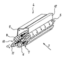
図3は現像剤搬送路内の現像剤の流れを説明する現像装置4の斜視断面図である。図中の各矢印は現像剤の移動方向を示している。
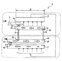
また、図4は、現像装置4内の現像剤の流れの模式図であり、図3と同様、図中の各矢印は現像剤の移動方向を示している。
Next, the circulation of the developer in the three developer conveyance paths will be described.
FIG. 3 is a perspective sectional view of the developing device 4 for explaining the flow of the developer in the developer transport path. Each arrow in the figure indicates the moving direction of the developer.
4 is a schematic diagram of the flow of the developer in the developing device 4. Like FIG. 3, each arrow in the drawing indicates the moving direction of the developer.

攪拌搬送路10から現像剤の供給を受けた供給搬送路9では、現像ローラ5に現像剤を供給しながら、供給スクリュ8の搬送方向下流側に現像剤を搬送する。そして、現像ローラ5に供給され現像に用いられず供給搬送路9の搬送方向下流端まで搬送された余剰現像剤は第一仕切り壁133の余剰開口部92より攪拌搬送路10に供給される(図4中矢印E)。
現像ローラ5から回収搬送路7に送られ、回収スクリュ6によって回収搬送路7の搬送方向下流端まで搬送された回収現像剤は第二仕切り壁134の回収開口部93より攪拌搬送路10に供給される(図4中矢印F)。
そして、攪拌搬送路10は、供給された余剰現像剤と回収現像剤とを攪拌し、攪拌スクリュ11の搬送方向下流側であり、供給スクリュ8の搬送方向上流側に搬送し、第一仕切り壁133の供給開口部91より供給搬送路9に供給される(図4中矢印D)。
攪拌搬送路10では攪拌スクリュ11によって、回収現像剤、余剰現像剤及び移送部で必要に応じて補給されるトナーを、回収搬送路7及び供給搬送路9の現像剤と逆方向に攪拌搬送する。そして、搬送方向下流側で連通している供給搬送路9の搬送方向上流側に攪拌された現像剤を移送する。なお、攪拌搬送路10の下方には、不図示のトナー濃度センサが設けられ、センサ出力により不図示のトナー補給制御装置を作動し、不図示のトナー収容部からトナー補給を行っている。
In the supply conveyance path 9 that has been supplied with the developer from the agitation conveyance path 10, the developer is conveyed downstream in the conveyance direction of the supply screw 8 while supplying the developer to the developing roller 5. Then, the excess developer that is supplied to the developing roller 5 and is not used for development and is transported to the downstream end in the transport direction of the supply transport path 9 is supplied to the stirring transport path 10 from the surplus opening 92 of the first partition wall 133 ( Arrow E) in FIG.
The collected developer that is sent from the developing roller 5 to the collection conveyance path 7 and conveyed to the downstream end in the conveyance direction of the collection conveyance path 7 by the collection screw 6 is supplied to the stirring conveyance path 10 from the collection opening 93 of the second partition wall 134. (Arrow F in FIG. 4).
The agitating and conveying path 10 agitates the supplied surplus developer and the recovered developer, conveys the agitating screw 11 to the downstream side in the conveying direction, and conveys it to the upstream side in the conveying direction of the supplying screw 8. It is supplied to the supply conveyance path 9 from the supply opening 91 of 133 (arrow D in FIG. 4).
In the agitating and conveying path 10, the agitating screw 11 agitates and conveys the collected developer, the surplus developer, and the toner replenished as necessary in the transfer unit in the direction opposite to the developer in the collecting and conveying path 7 and the supply conveying path 9. . Then, the agitated developer is transferred to the upstream side in the conveyance direction of the supply conveyance path 9 communicating with the downstream side in the conveyance direction. A toner concentration sensor (not shown) is provided below the agitation transport path 10, and a toner supply control device (not shown) is operated by the sensor output to supply toner from a toner storage portion (not shown).

図4に示す現像装置4では、供給搬送路9と回収搬送路7とを備え、現像剤の供給と回収とを異なる現像剤搬送路で行うので、現像済みの現像剤が供給搬送路9に混入することがない。よって、供給搬送路9の搬送方向下流側ほど現像ローラ5に供給される現像剤のトナー濃度が低下することを防止することができる。また、回収搬送路7と攪拌搬送路10とを備え、現像剤の回収と攪拌とを異なる現像剤搬送路で行うので、現像済みの現像剤が攪拌の途中に落ちることがない。よって、十分に攪拌がなされた現像剤が供給搬送路9に供給されるため、供給搬送路9に供給されるの現像剤が攪拌不足となることを防止することができる。このように、供給搬送路9内の現像剤のトナー濃度が低下することを防止し、供給搬送路9内の現像剤が攪拌不足となることを防止することができるので現像時の画像濃度を一定にすることができる。   In the developing device 4 shown in FIG. 4, a supply conveyance path 9 and a collection conveyance path 7 are provided, and developer supply and collection are performed in different developer conveyance paths, so that the developed developer is supplied to the supply conveyance path 9. There is no contamination. Accordingly, it is possible to prevent the toner density of the developer supplied to the developing roller 5 from decreasing toward the downstream side of the supply conveyance path 9 in the conveyance direction. Further, since the recovery conveyance path 7 and the agitation conveyance path 10 are provided and the developer recovery and agitation are performed in different developer conveyance paths, the developed developer does not fall during the agitation. Therefore, since the sufficiently agitated developer is supplied to the supply conveyance path 9, it is possible to prevent the developer supplied to the supply conveyance path 9 from being insufficiently agitated. In this way, the toner density of the developer in the supply conveyance path 9 can be prevented from decreasing, and the developer in the supply conveyance path 9 can be prevented from being insufficiently stirred. Can be constant.

なお、図4に示すように、現像装置4の下部から上部への現像剤の移動は矢印Dのみである。矢印Dで示す現像剤の移動は、攪拌スクリュ11の回転で現像剤を押し込むことにより、現像剤を盛り上がらせて供給搬送路9に現像剤を供給するものである。
このような現像剤の移動は、現像剤に対してストレスを与えることになり、現像剤の寿命低下の一因となる。
このような、現像剤を下方から上方に持ち上げる際に現像剤にストレスがかかり現像剤中のキャリアの膜削れやトナーのスペント化がその個所で発生し、それに伴い画像品質の安定性が保たれなくなってしまう。
よって、矢印Dで示す現像剤の移動における現像剤のストレスを軽減することで現像剤の長寿命化を図ることが出来る。現像剤の長寿命化を図ることにより、現像剤の劣化を防止して常に画像濃度ムラの無い画像品質の安定した現像装置を提供することができる。
As shown in FIG. 4, the developer moves from the lower part to the upper part of the developing device 4 only by the arrow D. The movement of the developer indicated by an arrow D is to push the developer by rotating the stirring screw 11 so that the developer is raised and supplied to the supply conveyance path 9.
Such movement of the developer gives stress to the developer and contributes to a decrease in the life of the developer.
When the developer is lifted from the bottom to the top, stress is applied to the developer, and the carrier film in the developer is scraped off and the toner is spent on the spot. Accordingly, the stability of the image quality is maintained. It will disappear.
Therefore, the life of the developer can be extended by reducing the stress of the developer in the movement of the developer indicated by the arrow D. By prolonging the life of the developer, it is possible to provide a developing device that prevents deterioration of the developer and is always stable in image quality without image density unevenness.

本実施形態の現像装置4では、図2に示すように、供給搬送路9を攪拌搬送路10の斜め上方になるように配置している。斜め上方に配置することにより、供給搬送路9を攪拌搬送路10の垂直上方に設け現像剤を持ち上げるものに比べて、矢印Dで示す現像剤の移動における現像剤のストレスを軽減することができる。
さらに、現像装置4では、供給搬送路9と攪拌搬送路10とを斜めに配置することで、図2に示すように、攪拌搬送路10の上部壁面が供給搬送路9の下部壁面よりも高い位置となるように配置している。
供給搬送路9を攪拌搬送路10に対して垂直上方に持ち上げることは、重力に逆らって現像剤を攪拌スクリュ11の圧によって持ち上げるので現像剤にストレスがかかる。一方、攪拌搬送路10の上部壁面が供給搬送路9の下部壁面よりも高い位置となるように配置することで、攪拌搬送路10の最高点に存在する現像剤が供給搬送路9の最下点に重力に逆らわず流れ込むことができるので、現像剤にかかるストレスを低減することができる。
なお、攪拌搬送路10の現像剤搬送路下流側の、攪拌搬送路10と供給搬送路9とが連通している部分の攪拌スクリュ11の軸にフィン部材を設けても良い。このフィン部材は攪拌スクリュ11の軸方向に平行な辺と、攪拌スクリュの軸方向に垂直な辺とから構成される板状の部材である。このフィン部材で現像剤を掻き上げることにより、攪拌搬送路10から供給搬送路9へ、より効率的な現像剤の受渡しを行うことができる。
In the developing device 4 of the present embodiment, as shown in FIG. 2, the supply conveyance path 9 is disposed obliquely above the stirring conveyance path 10. By disposing it obliquely above, it is possible to reduce the developer stress in the movement of the developer indicated by the arrow D, compared to the case where the supply conveyance path 9 is provided vertically above the stirring conveyance path 10 and the developer is lifted. .
Further, in the developing device 4, the supply conveyance path 9 and the agitation conveyance path 10 are arranged obliquely so that the upper wall surface of the agitation conveyance path 10 is higher than the lower wall surface of the supply conveyance path 9 as shown in FIG. 2. It arranges so that it may become a position.
Lifting the supply conveyance path 9 vertically upward with respect to the stirring conveyance path 10 causes the developer to be stressed because the developer is lifted by the pressure of the stirring screw 11 against gravity. On the other hand, the developer present at the highest point of the agitating and conveying path 10 is placed at the bottom of the supplying and conveying path 9 by arranging the upper wall surface of the agitating and conveying path 10 to be higher than the lower wall surface of the supplying and conveying path 9. Since the point can flow without being against gravity, the stress applied to the developer can be reduced.
Note that a fin member may be provided on the shaft of the stirring screw 11 in a portion where the stirring transport path 10 and the supply transport path 9 communicate with each other on the downstream side of the developer transport path of the stirring transport path 10. This fin member is a plate-like member composed of a side parallel to the axial direction of the stirring screw 11 and a side perpendicular to the axial direction of the stirring screw. By scooping up the developer with this fin member, it is possible to more efficiently deliver the developer from the stirring conveyance path 10 to the supply conveyance path 9.

また、現像装置4では、現像ローラ5と供給搬送路9との中心間距離Aが、現像ローラ5と攪拌搬送路10との中心間距離Bよりも短くなるように、供給搬送路9と攪拌搬送路10とを配置している。これにより供給搬送路9から現像ローラ5に現像剤を無理無く供給することができ、装置の小型化を図ることもできる。
また、攪拌スクリュ11は、図2中の手前側から見て反時計回り方向(図中矢印C方向)に回転しており、現像剤は攪拌スクリュ11の形状に沿って現像剤を持ち上げて供給搬送路9に移送させている。これにより、現像剤を効率良く持ち上げることが可能となり現像剤にかかるストレスもより低減することができる。
Further, in the developing device 4, the distance between the center A between the developing roller 5 and the supply conveyance path 9 is shorter than the distance B between the center between the development roller 5 and the agitation conveyance path 10. A conveyance path 10 is arranged. As a result, the developer can be supplied without difficulty from the supply conveyance path 9 to the developing roller 5, and the apparatus can be downsized.
Further, the stirring screw 11 is rotated counterclockwise as viewed from the front side in FIG. 2 (the direction of arrow C in the figure), and the developer is supplied by lifting the developer along the shape of the stirring screw 11. It is transferred to the conveyance path 9. As a result, the developer can be lifted efficiently, and the stress on the developer can be further reduced.

図5は、現像装置4の供給スクリュ8の回転中心における断面を図3中の矢印J方向から見た断面説明図である。図中Hは、現像剤担持体である現像ローラ5が、潜像担持体である感光体1にトナーを供給する現像領域を示している。この現像領域Hの現像ローラ5の回転軸の軸線方向の幅が現像領域幅αである。
図5に示すように、現像装置4は攪拌搬送路10から供給搬送路9に現像剤を持ち上げる箇所である供給開口部91と、供給搬送路9から攪拌搬送路10に現像剤を落下させる余剰開口部92とがともに現像領域幅α内に設けられている。
FIG. 5 is a cross-sectional explanatory view of the cross section at the rotation center of the supply screw 8 of the developing device 4 as viewed from the direction of arrow J in FIG. In the figure, H denotes a developing region in which the developing roller 5 that is a developer carrying member supplies toner to the photosensitive member 1 that is a latent image carrying member. The width in the axial direction of the rotation axis of the developing roller 5 in the developing area H is the developing area width α.
As shown in FIG. 5, the developing device 4 has a supply opening 91 that is a part for lifting the developer from the agitation conveyance path 10 to the supply conveyance path 9, and a surplus that drops the developer from the supply conveyance path 9 to the agitation conveyance path 10. Both of the openings 92 are provided in the development region width α.

図6は、図4とは異なる構成の現像装置4内の現像剤の流れの模式図である。
図6に示す現像装置4は、供給開口部91と余剰開口部92とを現像領域幅αの外側に設けている。供給開口部91を現像領域幅αの外側に設けているため、供給搬送路9の搬送方向上流側は現像ローラ5よりも供給搬送路上流側領域β分長くなっている。また、余剰開口部92を現像領域幅αの外側に設けているため、供給搬送路9の搬送方向下流側は現像ローラ5よりも供給搬送路下流側領域γ分長くなっている。
FIG. 6 is a schematic diagram of the developer flow in the developing device 4 having a configuration different from that in FIG. 4.
The developing device 4 shown in FIG. 6 is provided with a supply opening 91 and a surplus opening 92 outside the developing region width α. Since the supply opening 91 is provided outside the developing region width α, the upstream side in the transport direction of the supply transport path 9 is longer than the developing roller 5 by the upstream region β of the supply transport path. Further, since the surplus opening 92 is provided outside the developing region width α, the downstream side in the transport direction of the supply transport path 9 is longer than the developing roller 5 by the region γ on the downstream side of the supply transport path.

一方、図4に示す構成の現像装置4では、供給開口部91を現像領域幅α内に設けているため、供給搬送路9の搬送方向上流側は図6の現像装置4よりも供給搬送路上流側領域β分短くすることができる。また、余剰開口部92を現像領域幅α内に設けているため、供給搬送路9の搬送方向下流側は図6の現像装置4よりも供給搬送路下流側領域γ分短くすることができる。
このように、図4の現像装置4は供給開口部91と余剰開口部92とを現像領域幅α内に設けているため、図6に示す現像装置4に比べて、現像装置4の上部の省スペース化を図ることが出来る。
On the other hand, in the developing device 4 having the configuration shown in FIG. 4, since the supply opening 91 is provided within the developing region width α, the upstream side in the transport direction of the supply transport path 9 is on the supply transport path than the developing device 4 in FIG. The flow side region β can be shortened. Further, since the surplus opening 92 is provided in the developing area width α, the downstream side in the transport direction of the supply transport path 9 can be made shorter by the area γ on the downstream side of the supply transport path than the developing device 4 in FIG.
4 is provided with the supply opening 91 and the surplus opening 92 within the developing region width α, the upper portion of the developing device 4 is higher than that of the developing device 4 shown in FIG. Space saving can be achieved.

次に、現像装置4の供給搬送路9、攪拌搬送路10及び回収搬送路7からなる現像剤搬送路へのトナーを補給する位置について説明する。図7は、現像装置4の外観斜視図である。
図7に示すように、トナーを補給するトナー補給口95を攪拌スクリュ11を備える攪拌搬送路10の搬送方向上流端部の上方に設けている。このトナー補給口95は現像ローラ5の幅方向端部よりも外側に設けてあるので、現像領域幅αよりも外側となっている。
この、トナー補給口95を設けた箇所は供給搬送路9の搬送方向の延長線上であり、図6における供給搬送路下流側領域γの空いたスペースに該当する。余剰開口部92を現像領域幅α内に設けることで空いたスペースにトナー補給口95を設けることにより、現像装置4の小型化を図ることが出来る。
また、トナー補給口95としては、攪拌搬送路10の搬送方向上流端部の上方に限らず、回収搬送路7の下流端部の上方に設けても良い。
さらに、回収搬送路7から攪拌搬送路10へ現像剤の受渡しを行う箇所である回収開口部93の真上にトナー補給口95を設けるようにしても良い。回収開口部93の真上のスペースも余剰開口部92を現像領域幅α内に設けることで空いたスペースであるので、この位置にトナー補給口95を設けることにより、現像装置4の小型化を図ることができる。さらに、受渡し部である回収開口部93では現像剤が混ざりやすいため、この位置で補給を行うことによりより効率よく現像剤の攪拌を行うことができる。
Next, the position at which toner is supplied to the developer conveyance path including the supply conveyance path 9, the agitation conveyance path 10 and the collection conveyance path 7 of the developing device 4 will be described. FIG. 7 is an external perspective view of the developing device 4.
As shown in FIG. 7, a toner replenishing port 95 for replenishing toner is provided above the upstream end of the agitating and conveying path 10 including the agitating screw 11 in the conveying direction. Since the toner replenishing port 95 is provided outside the end portion in the width direction of the developing roller 5, it is outside the developing region width α.
The portion where the toner replenishing port 95 is provided is on an extension line in the conveyance direction of the supply conveyance path 9 and corresponds to a vacant space in the downstream area γ of the supply conveyance path in FIG. Providing the toner replenishment port 95 in an empty space by providing the surplus opening 92 within the developing region width α makes it possible to reduce the size of the developing device 4.
Further, the toner replenishing port 95 is not limited to the position above the upstream end portion in the transport direction of the stirring transport path 10 and may be provided above the downstream end portion of the collection transport path 7.
Further, a toner replenishing port 95 may be provided directly above the collection opening 93 where the developer is transferred from the collection conveyance path 7 to the stirring conveyance path 10. Since the space directly above the collection opening 93 is also an empty space provided by providing the surplus opening 92 within the developing region width α, the toner replenishing port 95 is provided at this position to reduce the size of the developing device 4. You can plan. Furthermore, since the developer is likely to be mixed in the collection opening 93 serving as a delivery unit, the developer can be more efficiently stirred by replenishing at this position.

図4を用いて説明した現像装置4のように、攪拌搬送路10の搬送方向下流端から供給搬送路9の搬送方向上流端に現像剤を受け渡す供給開口部91と、供給搬送路9の下流端から攪拌搬送路10の搬送方向上流端に現像剤を受け渡す余剰開口部92とを現像領域幅α内に設けているため、従来の現像装置4に比べて、現像装置4の上部の省スペース化を図ることが出来、現像装置4全体の省スペース化を図ることが出来る。
また、余剰開口部92を現像領域幅α内に設けることで空いたスペースにトナー補給口95を設けることにより、現像装置4の小型化を図ることが出来る。
また、回収搬送路7から攪拌搬送路10への現像剤の受渡し部である回収開口部93の上方からトナー補給を行うことによりより効率よく現像剤の攪拌を行うことができる。
また、画像形成装置としての複写機のプリンタ部100の現像手段として、現像装置4を備えることにより、装置全体の省スペース化を図ることが出来る。
As in the developing device 4 described with reference to FIG. 4, a supply opening 91 that transfers the developer from the downstream end in the transport direction of the stirring transport path 10 to the upstream end in the transport direction of the supply transport path 9, and the supply transport path 9 Since the surplus opening 92 for transferring the developer from the downstream end to the upstream end in the transport direction of the stirring transport path 10 is provided in the development region width α, the upper portion of the development device 4 is higher than the conventional development device 4. Space can be saved, and the space of the entire developing device 4 can be saved.
Also, by providing the toner replenishment port 95 in the empty space by providing the surplus opening 92 within the development region width α, the development device 4 can be downsized.
Further, the developer can be more efficiently stirred by replenishing the toner from above the recovery opening 93 that is a delivery portion of the developer from the recovery transport path 7 to the stirring transport path 10.
Further, by providing the developing device 4 as the developing means of the printer unit 100 of the copying machine as the image forming apparatus, it is possible to save the space of the entire apparatus.

次に、本実施形態の現像装置4の特徴部について説明する。
現像剤補給手段である不図示のトナー補給制御装置は、不図示のトナー収容部内のトナーをトナー補給口95から現像装置4に補給する。本実施形態の現像装置4では現像装置4のトナー補給口95からトナーとキャリアとを含む現像剤が補給される。以降、現像装置4に補給されるトナーとキャリアとが混合された現像剤をプレミックストナーと称する。
また、供給搬送路9には、供給搬送路9内の現像剤が所定の嵩を越えた場合にその一部を現像装置4の外部に排出する現像剤排出手段として、排出搬送路2と現像剤排出口94とを有する。排出搬送路2は、供給搬送路9の搬送方向下流側で仕切り壁135を挟んで供給搬送路9と隣り合うように配置され、現像剤排出口94は供給搬送路9と排出搬送路2とを連通するように仕切り壁135に設けられた開口である。
そして、本実施形態の現像装置4は、図4に示すように、供給搬送路9の搬送方向下流端近傍に現像剤排出口94を配置して、供給搬送路9の搬送方向下流端近傍の現像剤が所定量の嵩を越えた場合にその一部を排出する。
なお、供給搬送路9の搬送方向下流端近傍とは、例えば、供給搬送路9から攪拌搬送路10へと現像剤が受け渡される現像剤受渡し部と供給搬送路9の搬送方向で同位置となる箇所である。言い換えると、供給スクリュ8による搬送力が終了するところであり、後述する逆スクリュによる搬送力がかかる直前部分のことである。ここに現像剤排出口94を設けることにより、供給スクリュ8によって搬送された後、逆スクリュの搬送力により受け止められ、最終的にたまった現像剤を現像剤排出口94から排出することが可能になる。また、現像装置4では逆スクリュがついているが、供給スクリュ8によって搬送された現像剤が現像剤排出口94の位置で溜まるように搬送力が途切れれば良いため、供給搬送路9の最下流側端面は壁状となっていてもかまわない。
Next, the characteristic part of the developing device 4 of the present embodiment will be described.
A toner replenishment control device (not shown) that is a developer replenishing unit replenishes toner in a toner storage unit (not shown) to the developing device 4 from the toner replenishing port 95. In the developing device 4 of this embodiment, a developer including toner and a carrier is supplied from a toner supply port 95 of the developing device 4. Hereinafter, the developer in which the toner supplied to the developing device 4 and the carrier are mixed is referred to as premix toner.
Further, the supply conveyance path 9 is connected to the discharge conveyance path 2 and the development unit as developer discharge means for discharging a part of the developer in the supply conveyance path 9 to the outside of the developing device 4 when the developer exceeds a predetermined volume. Agent discharge port 94. The discharge conveyance path 2 is disposed on the downstream side in the conveyance direction of the supply conveyance path 9 so as to be adjacent to the supply conveyance path 9 with the partition wall 135 interposed therebetween, and the developer discharge port 94 is connected to the supply conveyance path 9 and the discharge conveyance path 2. Is an opening provided in the partition wall 135 so as to communicate with each other.
In the developing device 4 of the present embodiment, as shown in FIG. 4, a developer discharge port 94 is disposed in the vicinity of the downstream end in the transport direction of the supply transport path 9, and in the vicinity of the downstream end in the transport direction of the supply transport path 9. When the developer exceeds a predetermined amount, a part of the developer is discharged.
The vicinity of the downstream end of the supply conveyance path 9 in the conveyance direction is, for example, the same position in the conveyance direction of the developer conveyance section 9 and the supply conveyance path 9 where the developer is transferred from the supply conveyance path 9 to the stirring conveyance path 10. It is a place. In other words, it is where the conveying force by the supply screw 8 ends, and is the portion immediately before the conveying force by the reverse screw described later is applied. By providing the developer discharge port 94 here, after being conveyed by the supply screw 8, it is received by the conveying force of the reverse screw, and finally the developer accumulated can be discharged from the developer discharge port 94. Become. Although the developing device 4 has a reverse screw, it is sufficient that the conveying force is interrupted so that the developer conveyed by the supply screw 8 accumulates at the position of the developer discharge port 94. The side end surface may be a wall shape.

図8は、現像装置4から攪拌スクリュ11、回収スクリュ6、及び、現像ドクタ12を取り外した状態の手前側端部近傍の斜視説明図である。また、図9は、現像装置4について図8の状態からさらに供給スクリュ8を取り外した状態の手前側近傍を図9とは異なる方向から見た斜視説明図である。さらに、図10は、現像装置4について図9の状態からさらに現像ローラ5を取り外した状態の斜視説明図である。また、図11は、現像装置4について図10と同じ状態の現像装置4を図3と略同じ方向から見た場合の斜視説明図である。   FIG. 8 is an explanatory perspective view of the vicinity of the front end portion in a state where the stirring screw 11, the recovery screw 6, and the developing doctor 12 are removed from the developing device 4. FIG. 9 is an explanatory perspective view of the developing device 4 in the vicinity of the near side in a state where the supply screw 8 is further removed from the state of FIG. Further, FIG. 10 is a perspective explanatory view of the developing device 4 with the developing roller 5 further removed from the state of FIG. FIG. 11 is a perspective explanatory view of the developing device 4 when the developing device 4 in the same state as FIG. 10 is viewed from substantially the same direction as FIG.

供給スクリュ8の回転方向は、図2でいうところの右回り(矢印Mの方向)であって、現像ローラ5に対して現像剤を下方から持ち上げて供給する方向に回転している。ここで、供給スクリュ8の回転方向を左回りにし、現像剤を上から振り掛けるようにして現像ローラ5に現像剤を供給すると、現像剤が飛び散りながら現像ローラ5に供給される。一方、供給スクリュ8の回転方向を図2に示すように右回りにすると、現像剤がたまっている供給搬送路9の下方から現像剤を持ち上げるようにして現像ローラ5に現像剤が供給されるようになる。現像剤が飛び散りながら供給するよりも、下方から持ち上げるようにして供給するほうが現像剤の供給性が安定するため、現像装置4では供給スクリュ8の回転方向を図2でいうところの右回りに設定している。
特に本実施形態の現像装置4のように現像ローラ5に供給した現像剤を供給搬送路9へ戻さず、回収搬送路7へ回収するものでは、現像剤量は供給搬送路9の下流に行くにしたがって減少していく。このため、現像剤がたまっている下方からくみ上げて現像ローラ5に供給するもののほうが現像剤の供給性の面では優れている。
The rotation direction of the supply screw 8 is clockwise (the direction of the arrow M) as shown in FIG. 2, and is rotated in the direction in which the developer is lifted and supplied from below. Here, when the developer is supplied to the developing roller 5 so that the rotation direction of the supply screw 8 is counterclockwise and the developer is sprinkled from above, the developer is supplied to the developing roller 5 while being scattered. On the other hand, when the rotation direction of the supply screw 8 is clockwise as shown in FIG. 2, the developer is supplied to the developing roller 5 so as to lift the developer from below the supply conveyance path 9 where the developer is accumulated. It becomes like this. The developer supply performance is more stable when the developer is supplied by lifting from the lower side than when the developer is supplied while being scattered. Therefore, in the developing device 4, the rotation direction of the supply screw 8 is set clockwise as shown in FIG. is doing.
In particular, in the case where the developer supplied to the developing roller 5 is not returned to the supply conveyance path 9 but is collected to the collection conveyance path 7 as in the developing device 4 of this embodiment, the amount of developer goes downstream of the supply conveyance path 9. It decreases according to. For this reason, it is more excellent in terms of developer supply that the developer is drawn up from below and supplied to the developing roller 5.

ここで、供給搬送路9内では、搬送されることで供給搬送路9内を移動する勢いや、現像剤搬送スクリュである供給スクリュ8の回転する力によって供給搬送路9内の現像剤は飛び跳ねる。そして、現像剤搬送路である供給搬送路9の所定の高さに現像剤排出口94を設けただけの構成であると、飛び跳ねた現像剤が飛翔して現像剤排出口94を通過して排出されることがある。現像剤が飛び跳ねて排出される場合、供給搬送路9内の現像剤排出口94を設けた位置を搬送される現像剤が適正な量の状態や、適正な量を下回る状態であっても、飛び跳ねた現像剤が排出されるおそれがある。このように飛び跳ねた現像剤が排出される状態であると、現像装置4内の現像剤が適正な量以下の状態であるにもかかわらず現像剤排出口から現像剤が排出されることがあり、現像装置4内の現像剤量が必要量を下回り、感光体1への現像剤の供給が不安定になるおそれがある。そして、感光体1への現像剤の供給が不安定になると画像抜けなどの異常画像が発生する。   Here, in the supply conveyance path 9, the developer in the supply conveyance path 9 jumps by the momentum of movement in the supply conveyance path 9 by being conveyed and the rotating force of the supply screw 8 that is a developer conveyance screw. . When the developer discharge port 94 is simply provided at a predetermined height of the supply conveyance path 9 that is the developer conveyance path, the jumped developer flies and passes through the developer discharge port 94. May be discharged. When the developer jumps and is discharged, even if the developer transported through the position where the developer discharge port 94 in the supply transport path 9 is provided is in an appropriate amount or less than the appropriate amount, The jumped developer may be discharged. In such a state where the developer jumped off is discharged, the developer may be discharged from the developer discharge port even though the amount of the developer in the developing device 4 is not more than an appropriate amount. The amount of developer in the developing device 4 is less than the required amount, and the supply of developer to the photoreceptor 1 may become unstable. When the developer supply to the photosensitive member 1 becomes unstable, an abnormal image such as image omission occurs.

このような不具合を防止するために、現像装置4は、現像剤搬送部材のうちの供給搬送部材である供給スクリュ8が現像剤を搬送するために回転することによって飛翔した現像剤が現像剤排出口94に向かう経路を塞ぐ飛翔現像剤排出防止部材として、ブロック部材3を備えている。ブロック部材3を備え、供給スクリュ8の搬送動作によって飛翔した現像剤が現像剤排出口94へ向かう経路を塞ぐため、飛び跳ねた現像剤が排出されることを防止し、現像装置4内の現像剤量が増加していないにもかかわらず現像剤が排出されることを防止することができる。このため、現像装置4内の現像剤の必要量を確保することができ、感光体1に安定した現像剤の供給を行うことができる。これにより、感光体1上の静電潜像を良好にトナー像化することができ、画像抜けなどの異常画像の発生を防止し、良好な画像形成を行うことができる。   In order to prevent such inconvenience, the developing device 4 is configured so that the developer flying off when the supply screw 8 which is a supply conveying member among the developer conveying members rotates to convey the developer is discharged from the developer. A block member 3 is provided as a flying developer discharge preventing member that blocks the path toward the outlet 94. The developer in the developing device 4 is provided with the block member 3, and the developer flying by the feeding operation of the supply screw 8 blocks the path toward the developer discharge port 94, thereby preventing the jumped developer from being discharged. It is possible to prevent the developer from being discharged even though the amount is not increased. Therefore, the necessary amount of developer in the developing device 4 can be secured, and the developer can be stably supplied to the photoreceptor 1. As a result, the electrostatic latent image on the photoreceptor 1 can be favorably converted into a toner image, an abnormal image such as image omission can be prevented, and good image formation can be performed.

ブロック部材3は、その底面が供給搬送路9の上部に供給スクリュ8の形状に沿ったR形状の樹脂製の部材である。供給スクリュ8の形状に沿ったR形状であることにより、供給スクリュ8全体を覆うようにブロック部材3の底面を全体的に供給スクリュ8に近接させることが可能になる。このため、現像剤の跳ね上げを起こす供給スクリュ8の上方を覆い、供給スクリュ8によって跳ね上げられた現像剤が現像剤排出口94へ飛翔することを防止することができる。   The block member 3 is an R-shaped resin member whose bottom surface follows the shape of the supply screw 8 above the supply conveyance path 9. Due to the R shape along the shape of the supply screw 8, the bottom surface of the block member 3 can be brought close to the supply screw 8 as a whole so as to cover the entire supply screw 8. For this reason, it is possible to cover the upper portion of the supply screw 8 that causes the developer to jump up, and to prevent the developer jumped up by the supply screw 8 from flying to the developer discharge port 94.

また、図11に示すように、供給搬送路9の現像剤排出口94周辺でブロック部材3が突出した形状となっているため、ブロック部材3に対して供給スクリュ8の搬送方向上流側の供給搬送路9よりも、ブロック部材3を設けた箇所の供給搬送路が狭くなっている。このため、ブロック部材3を設けた位置に対して搬送方向上流側よりも、ブロック部材3を設けた位置の方が供給搬送路9の容量に対する現像剤量が多くなる。そのため、現像剤に対して搬送力の付与が無くなる供給搬送路9の搬送方向下流端部近傍で、ブロック部材3の側壁と、仕切り壁135との間に現像剤がせり上がる状態となる。これにより、供給スクリュ8が現像剤に埋まるような状態となり、供給スクリュ8の回転による現像剤の跳ね上げが抑えられるとともに、供給スクリュ8の羽部の上部が現像剤の剤面から出ているときに発生する供給スクリュの跳ね上げによる剤面の変化が現像剤排出口94付近では緩和される。このため、現像装置4内の現像剤の増減に対して感度の良い排出が望めるようになる。
このようなブロック部材3を備えることで、現像剤の供給により嵩が上昇した場合、増加した分に相当する現像剤が現像剤排出口94より溢れ出す構成となっている。
Further, as shown in FIG. 11, since the block member 3 protrudes around the developer discharge port 94 of the supply conveyance path 9, the supply screw 8 on the upstream side in the conveyance direction of the supply screw 8 with respect to the block member 3. The supply conveyance path where the block member 3 is provided is narrower than the conveyance path 9. Therefore, the developer amount with respect to the capacity of the supply conveyance path 9 is larger at the position where the block member 3 is provided than at the upstream side in the conveyance direction with respect to the position where the block member 3 is provided. Therefore, the developer rises between the side wall of the block member 3 and the partition wall 135 in the vicinity of the downstream end in the conveyance direction of the supply conveyance path 9 where no conveyance force is applied to the developer. As a result, the supply screw 8 is buried in the developer, and the splashing of the developer due to the rotation of the supply screw 8 is suppressed, and the upper part of the wing portion of the supply screw 8 protrudes from the developer surface. A change in the surface of the material caused by the splashing of the supply screw that occurs sometimes is mitigated in the vicinity of the developer discharge port 94. For this reason, it is possible to expect discharge with high sensitivity to increase / decrease of the developer in the developing device 4.
By providing such a block member 3, when the bulk increases due to the supply of the developer, the developer corresponding to the increased amount overflows from the developer discharge port 94.

図12及び図13は、現像装置4内の現像剤量が少ない状態、すなわち、供給搬送路9の搬送方向下流端近傍の現像剤の嵩が所定の高さに到達していない状態の現像装置4の現像剤の流れを示す説明図である。図12は、図2と同じ方向から見た供給搬送路9の搬送方向下流端近傍の現像装置4の断面説明図であり、図13は、図5と同じ方向から見た側方断面説明図である。図中Pは現像剤を示す。
図12及び図13に示すように、現像装置4内の現像剤量が少ない場合は供給搬送路9から循環搬送路である攪拌搬送路10への現像剤の供給がスムーズに行われる。その結果、供給搬送路9と攪拌搬送路10との境界である供給循環仕切り壁である第一仕切り壁133に設けられた開口部である供給循環連通口としての余剰開口部92で現像剤Pが溢れることが無い。このため、現像装置4外へ現像剤Pを排出する現像剤排出口94へ現像剤はほとんど導かれず、現像剤量が少ない状態で現像剤が排出されることを防止することができる。
12 and 13 show the developing device in a state where the amount of developer in the developing device 4 is small, that is, in a state where the volume of the developer near the downstream end in the transport direction of the supply transport path 9 has not reached a predetermined height. FIG. 4 is an explanatory diagram showing a flow of developer 4. 12 is a cross-sectional explanatory view of the developing device 4 in the vicinity of the downstream end in the transport direction of the supply transport path 9 as viewed from the same direction as FIG. 2, and FIG. 13 is a side cross-sectional explanatory view as viewed from the same direction as FIG. It is. In the figure, P indicates a developer.
As shown in FIGS. 12 and 13, when the amount of developer in the developing device 4 is small, the developer is smoothly supplied from the supply conveyance path 9 to the stirring conveyance path 10 that is a circulation conveyance path. As a result, the developer P in the surplus opening 92 serving as a supply circulation communication port, which is an opening provided in the first partition wall 133 that is a supply circulation partition wall that is a boundary between the supply conveyance path 9 and the stirring conveyance path 10. There is no overflow. For this reason, the developer is hardly led to the developer discharge port 94 for discharging the developer P to the outside of the developing device 4, and it is possible to prevent the developer from being discharged in a state where the amount of the developer is small.

図14及び図15は現像装置4内の現像剤量が多い状態、すなわち、供給搬送路9の搬送方向下流端近傍の現像剤Pの嵩が所定の高さに越えた状態の現像装置4の現像剤Pの流れを示す説明図である。図14は、図2と同じ方向から見た供給搬送路9の搬送方向下流端近傍の現像装置4の断面説明図であり、図15は、図5と同じ方向から見た側方断面説明図である。
図14及び図15に示すように、現像装置4内の現像剤量が多い場合は、供給搬送路9から攪拌搬送路10へ現像剤Pが移動する余剰開口部92の近傍で現像剤Pが滞留してしまう。その結果、供給搬送路9の搬送方向最下流部の現像剤Pは行き場が無くなり上方向に嵩が上昇して行く。そして、現像剤排出口94の高さまで嵩が上昇すると現像剤Pが排出搬送路2へと排出され、排出搬送路2内の排出搬送部材である排出搬送スクリュ2aによって現像装置4の外部に排出されることになる。
14 and 15 show the state of the developing device 4 in a state where the amount of the developer in the developing device 4 is large, that is, in the state where the volume of the developer P near the downstream end in the transport direction of the supply transport path 9 exceeds a predetermined height. 5 is an explanatory diagram showing a flow of developer P. FIG. 14 is a cross-sectional explanatory view of the developing device 4 near the downstream end in the transport direction of the supply transport path 9 as viewed from the same direction as FIG. 2, and FIG. 15 is a side cross-sectional explanatory view as viewed from the same direction as FIG. It is.
As shown in FIGS. 14 and 15, when the amount of developer in the developing device 4 is large, the developer P is near the surplus opening 92 where the developer P moves from the supply conveyance path 9 to the stirring conveyance path 10. It will stay. As a result, the developer P at the most downstream portion in the transport direction of the supply transport path 9 has no place to go and the volume increases upward. When the bulk increases to the height of the developer discharge port 94, the developer P is discharged to the discharge conveyance path 2, and discharged to the outside of the developing device 4 by the discharge conveyance screw 2a that is a discharge conveyance member in the discharge conveyance path 2. Will be.

現像装置4は、供給搬送路9の搬送方向下流端近傍の現像剤の嵩が現像剤排出口94の高さを越えた場合に、現像剤排出口94の高さまで到達した現像剤を排出するものであるので、現像剤排出口94からの現像剤の排出によって供給搬送路9を搬送する現像剤が不足することを防止することができる。これにより、供給搬送路9から現像ローラ5へ必要量の現像剤を供給することができ、現像ローラ5から感光体1に安定した現像剤の供給を行うことができる。このため、感光体1上の静電潜像を良好にトナー像化することができ、画像抜けなどの異常画像の発生を防止し、良好な画像形成を行うことができる。   The developing device 4 discharges the developer that has reached the height of the developer discharge port 94 when the bulk of the developer in the vicinity of the downstream end in the transport direction of the supply transport path 9 exceeds the height of the developer discharge port 94. Therefore, it is possible to prevent a shortage of developer transporting the supply transport path 9 due to the discharge of the developer from the developer discharge port 94. Accordingly, a necessary amount of developer can be supplied from the supply conveyance path 9 to the developing roller 5, and the developer can be stably supplied from the developing roller 5 to the photosensitive member 1. For this reason, the electrostatic latent image on the photosensitive member 1 can be favorably converted into a toner image, an abnormal image such as image omission can be prevented, and good image formation can be performed.

図13では、現像装置4内の現像剤が少ない状態について説明したが、現像装置4内の現像剤が排出されず、現像剤量が安定した状態では、供給搬送路9の搬送方向下流端近傍に現像剤が滞留した状態となっている。以下、この状態の詳細について説明する。
現像装置4は、現像剤排出手段が、供給搬送路9の搬送方向下流端近傍の現像剤の嵩が所定の高さを越えた場合にその一部を排出する構成である。すなわち、現像剤排出手段である現像剤排出口94及び排出搬送路2は、供給搬送路9の搬送方向下流端近傍の現像剤の嵩が、現像剤排出口94の高さまで到達した現像剤を排出するものである。よって、供給搬送路9の搬送方向下流端近傍に、現像剤排出口94の高さに到達しない程度の嵩で現像剤が存在する状態で現像装置4内の現像量が安定した状態となる。これは、供給搬送路9を搬送されその搬送方向下流端に到達する現像剤量と、供給搬送路9余剰開口部92を通って攪拌搬送路10に受け渡される現像剤量との均衡により、供給搬送路9の搬送方向下流端近傍に現像剤排出口94の高さに到達しない程度の嵩で現像剤が滞留している状態である。
In FIG. 13, the state in which the developer in the developing device 4 is small has been described. However, when the developer in the developing device 4 is not discharged and the developer amount is stable, the vicinity of the downstream end in the transport direction of the supply transport path 9 In this state, the developer is retained. Details of this state will be described below.
In the developing device 4, the developer discharging means discharges a part of the developer when the volume of the developer near the downstream end in the transport direction of the supply transport path 9 exceeds a predetermined height. In other words, the developer discharge port 94 and the discharge conveyance path 2 which are developer discharge means are configured so that the developer bulk near the downstream end in the conveyance direction of the supply conveyance path 9 reaches the height of the developer discharge port 94. To be discharged. Therefore, the developing amount in the developing device 4 is stable in a state where the developer is present in the vicinity of the downstream end of the supply conveying path 9 in the conveying direction so as not to reach the height of the developer discharge port 94. This is due to the balance between the amount of developer transported through the supply transport path 9 and reaching the downstream end in the transport direction, and the amount of developer delivered to the stirring transport path 10 through the supply transport path 9 surplus opening 92. In this state, the developer stays in a volume that does not reach the height of the developer discharge port 94 in the vicinity of the downstream end of the supply conveyance path 9 in the conveyance direction.

この状態からトナー補給制御装置によってプレミックストナーが供給されて現像装置4内の現像剤量が増加すると、供給搬送路9から攪拌搬送路10に受け渡される現像剤量よりも、供給搬送路9を搬送されその搬送方向下流端に到達する現像剤量の方が多くなる。このとき、供給搬送路9の搬送方向下流端近傍に滞留する現像剤の量が増加し、その嵩が上昇する。これにより、滞留する現像剤の嵩が現像剤排出口94に到達した場合に、その嵩が現像剤排出口94の位置よりも低くなるように滞留する現像剤の一部として、現像剤排出口94に到達した現像剤を排出する。
滞留する現像剤は飛び跳ねにくく、現像装置4内の現像剤量の増減に合わせて現像剤の嵩が変化する。そして、その嵩が所定の高さを越えたときに現像剤を排出することにより、現像装置4内の現像剤量が増加したときに増加量分の現像剤が排出されるため、現像装置4内の現像剤量を精度良く一定の範囲内に維持することができる。
これにより、供給搬送路9を搬送される現像剤量が安定するため、供給搬送路を搬送する現像剤が不足することを防止することができ、供給搬送路9から現像ローラ5へ必要量の現像剤を供給することができる。このため、現像ローラ5から感光体1に安定した現像剤の供給を行うことができ、感光体1上の静電潜像を良好にトナー像化することができるため、画像抜けなどの異常画像の発生を防止し、良好な画像形成を行うことができる。
When the premix toner is supplied by the toner replenishment control device from this state and the amount of developer in the developing device 4 increases, the supply conveyance path 9 is more than the amount of developer delivered from the supply conveyance path 9 to the stirring conveyance path 10. The amount of developer that reaches the downstream end in the transport direction is increased. At this time, the amount of the developer staying in the vicinity of the downstream end in the transport direction of the supply transport path 9 is increased, and the bulk thereof is increased. As a result, when the volume of the staying developer reaches the developer discharge port 94, the developer discharge port is used as a part of the developer that stays so that the bulk becomes lower than the position of the developer discharge port 94. The developer reaching 94 is discharged.
The staying developer is unlikely to jump, and the volume of the developer changes according to the increase or decrease of the developer amount in the developing device 4. Since the developer is discharged when the bulk exceeds a predetermined height, when the amount of developer in the developing device 4 increases, the increased amount of developer is discharged. It is possible to maintain the developer amount within a certain range with high accuracy.
As a result, the amount of developer conveyed through the supply conveyance path 9 is stabilized, so that it is possible to prevent a shortage of developer conveying along the supply conveyance path, and a necessary amount from the supply conveyance path 9 to the developing roller 5 can be prevented. Developer can be supplied. For this reason, a stable developer can be supplied from the developing roller 5 to the photosensitive member 1, and the electrostatic latent image on the photosensitive member 1 can be favorably formed into a toner image. Can be prevented and good image formation can be performed.

現像装置4において、プレミックストナーが補給されたときの攪拌スクリュ11による現像剤の搬送量の変化や攪拌搬送路10から供給搬送路9への現像剤の受渡し量の変化によって現像剤の現像剤の動向は異なる。
例えば、プレミックストナーが補給された状態でも攪拌スクリュ11による現像剤の搬送量があまり変化しない場合は、供給搬送路9の搬送方向上流側に供給される現像剤の量もあまり変化しない。また、攪拌搬送路10から供給搬送路9へ現像剤を受け渡す構成が、図12や図13に示す状態で時間当りに受け渡せる量の上限に近い状態である場合も供給搬送路9の搬送方向上流側に供給される現像剤の量もあまり変化しない。これらの構成は、現像装置4内の現像剤量が増加することで攪拌搬送路10内の現像剤量が増加し、攪拌搬送路10内に時間当りに供給される現像剤量が増加する量に比べて、攪拌搬送路から供給搬送路9へと時間当りに移動する現像剤量の増加する量が少なくなる構成である。
In the developing device 4, the developer developer by the change in the developer conveyance amount by the stirring screw 11 when the premix toner is replenished or the change in the developer delivery amount from the stirring conveyance path 10 to the supply conveyance path 9. Trends are different.
For example, when the amount of developer transported by the stirring screw 11 does not change much even when the premix toner is supplied, the amount of developer supplied upstream in the transport direction of the supply transport path 9 does not change much. Further, even when the configuration in which the developer is transferred from the agitation conveyance path 10 to the supply conveyance path 9 is close to the upper limit of the amount that can be delivered per time in the state shown in FIGS. The amount of developer supplied upstream in the direction does not change much. In these configurations, the amount of developer in the agitation transport path 10 increases as the amount of developer in the developing device 4 increases, and the amount of developer supplied per time in the agitation transport path 10 increases. As compared with the above, the amount of the developer that moves from the stirring conveyance path to the supply conveyance path 9 per unit time increases is reduced.

このような構成の現像装置4では、プレミックストナーが補給されても、供給搬送路9を搬送される現像剤量も変化せず、供給搬送路9から現像ローラ5に供給される現像剤量も略一定であるので、供給スクリュ8によって時間当りに供給搬送路9の搬送方向下流端近傍に到達する現像剤の量もほとんど変化しない。
一方、攪拌搬送路10の搬送量があまり変化しない場合は、トナー補給口95からプレミックストナーが補給されると、増加した現像剤は攪拌搬送路10の搬送方向上流端近傍で滞留する。また、攪拌搬送路10から供給搬送路9への受渡し量が変化しない場合は、増加した分の現像剤は攪拌搬送路10内で滞留し、搬送方向上流端近傍にも滞留する。
搬送方向上流端近傍に現像剤が滞留すると、供給搬送路9から攪拌搬送路10へ現像剤を受け渡す余剰開口部92を攪拌搬送路10側で現像剤によって塞ぐ状態となる。余剰開口部92が現像剤によって塞がれると供給搬送路9から攪拌搬送路10への現像剤の移動ができなくなるが、供給スクリュ8によって現像剤が搬送され続けるため、供給搬送路9の搬送方向下流端近傍で現像剤が滞留し、その嵩は増加する。そして、供給搬送路9の搬送方向下流端近傍の現像剤の嵩が、現像剤排出口94の高さまで上昇すると現像剤Pが排出搬送路2へと排出され、排出搬送路2を通って現像装置4の外部に排出される。
この構成では、攪拌搬送路10内に現像剤が充満状態のときに、現像に用いられずに供給搬送路9の搬送方向の最下流まで搬送された余剰現像剤を攪拌搬送路10に供給搬送する余剰開口部92が現像剤で溢れる状態とすることにより、供給搬送路9から攪拌搬送路10への現像剤の移動を規制することができその結果行き場を失った現像剤は現像剤排出口94へと導かれ、現像剤を排出ことが可能となる。
このように、現像装置4内の現像剤量が増加しても攪拌搬送路10から供給搬送路9へ時間当りに供給される現像剤量があまり変化しない構成であっても、供給搬送路9の搬送方向下流端に現像剤排出口94を配置することにより、現像装置4内の現像剤の入れ替えを行うことができる。
In the developing device 4 having such a configuration, even when the premix toner is replenished, the amount of developer conveyed through the supply conveyance path 9 does not change, and the amount of developer supplied from the supply conveyance path 9 to the developing roller 5 is changed. Therefore, the amount of the developer reaching the vicinity of the downstream end in the transport direction of the supply transport path 9 per time by the supply screw 8 hardly changes.
On the other hand, when the conveyance amount of the agitation conveyance path 10 does not change much, when the premix toner is replenished from the toner replenishing port 95, the increased developer stays in the vicinity of the upstream end of the agitation conveyance path 10 in the conveyance direction. Further, when the delivery amount from the agitation conveyance path 10 to the supply conveyance path 9 does not change, the increased amount of developer stays in the agitation conveyance path 10 and also stays in the vicinity of the upstream end in the conveyance direction.
When the developer stays in the vicinity of the upstream end in the transport direction, the surplus opening 92 that delivers the developer from the supply transport path 9 to the stirring transport path 10 is closed by the developer on the stirring transport path 10 side. When the excess opening 92 is blocked by the developer, the developer cannot be moved from the supply conveyance path 9 to the stirring conveyance path 10, but the developer is continuously conveyed by the supply screw 8, so that the conveyance of the supply conveyance path 9 is performed. The developer stays in the vicinity of the downstream end in the direction, and its bulk increases. When the volume of the developer near the downstream end in the conveyance direction of the supply conveyance path 9 rises to the height of the developer discharge port 94, the developer P is discharged to the discharge conveyance path 2 and developed through the discharge conveyance path 2. It is discharged outside the device 4.
In this configuration, when the developer in the agitation transport path 10 is full, the excess developer that has been transported to the most downstream side in the transport direction of the supply transport path 9 without being used for development is supplied and transported to the agitation transport path 10. By setting the surplus opening 92 to overflow with the developer, the movement of the developer from the supply conveyance path 9 to the agitation conveyance path 10 can be restricted, and as a result, the developer that has lost its destination is the developer discharge port. Then, the developer can be discharged.
As described above, even if the developer amount in the developing device 4 increases, even if the developer amount supplied per hour from the agitation transport path 10 to the supply transport path 9 does not change much, the supply transport path 9 By disposing the developer discharge port 94 at the downstream end in the transport direction, the developer in the developing device 4 can be replaced.

また、プレミックストナーが補給されると、それに併せて供給搬送路9の搬送方向上流側に供給される現像剤の量が増加するが、供給搬送路9から攪拌搬送路10への現像剤の受渡し量に上限があるものがある構成もある。この構成は、現像装置4内の現像剤量が増加することで供給搬送路9内の現像剤量が増加し、供給スクリュ8の搬送によって供給搬送路9の搬送方向下流端近傍に時間当りに搬送される現像剤量が増加する量に比べて、供給搬送路9の搬送方向下流端から攪拌搬送路10へと時間当りに移動する現像剤量の増加する量が少なくなるように構成されている。
このような構成の現像装置4では、プレミックストナーが補給されると、現像剤の増化に合わせて攪拌搬送路10の搬送量が増加し、攪拌搬送路10から供給搬送路9への現像剤の受渡し量も増加する。これにより、供給搬送路9の搬送方向上流端部に供給される現像剤量が増加し、供給搬送路9内を搬送する現像剤量も増加する。しかし、供給搬送路9から現像ローラ5に供給される現像剤量は変化しないため、時間当りに供給搬送路9の搬送方向下流端近傍に到達する現像剤量は増加する。そして、時間当りに供給搬送路9の搬送方向下流端近傍に到達する現像剤量が、供給搬送路9から攪拌搬送路10への現像剤の時間当りの受渡し量の上限を越えると、供給搬送路9の搬送方向下流端近傍で現像剤が滞留し、その嵩は増加する。そして、供給搬送路9の搬送方向下流端近傍の現像剤の嵩が、現像剤排出口94の高さまで上昇すると現像剤Pが排出搬送路2へと排出され、排出搬送路2を通って現像装置4の外部に排出される。
このように、現像装置4内の現像剤量が増加すると攪拌搬送路10から供給搬送路9へ時間当りに供給される現像剤量も増加する構成であっても、供給搬送路9の搬送方向下流端に現像剤排出口94を配置することにより、現像装置4内の現像剤の入れ替えを行うことができる。
In addition, when the premix toner is replenished, the amount of the developer supplied to the upstream side of the supply conveyance path 9 in the conveyance direction increases, but the amount of developer from the supply conveyance path 9 to the stirring conveyance path 10 increases. Some configurations have an upper limit on the delivery amount. In this configuration, as the amount of developer in the developing device 4 increases, the amount of developer in the supply conveyance path 9 increases, and the conveyance of the supply screw 8 near the downstream end in the conveyance direction of the supply conveyance path 9 per time. Compared with the amount by which the amount of developer conveyed increases, the amount of developer that moves per hour from the downstream end in the conveyance direction of the supply conveyance path 9 to the agitation conveyance path 10 is reduced. Yes.
In the developing device 4 having such a configuration, when the premix toner is replenished, the conveyance amount of the agitation conveyance path 10 increases as the developer increases, and development from the agitation conveyance path 10 to the supply conveyance path 9 occurs. The amount of drug delivery will also increase. As a result, the amount of developer supplied to the upstream end of the supply conveyance path 9 in the conveyance direction increases, and the amount of developer conveyed in the supply conveyance path 9 also increases. However, since the amount of developer supplied from the supply conveyance path 9 to the developing roller 5 does not change, the amount of developer that reaches the vicinity of the downstream end in the conveyance direction of the supply conveyance path 9 increases per time. When the amount of developer that reaches the vicinity of the downstream end in the conveyance direction of the supply conveyance path 9 per time exceeds the upper limit of the delivery amount of developer from the supply conveyance path 9 to the stirring conveyance path 10 per hour, the supply conveyance The developer stays in the vicinity of the downstream end of the path 9 in the transport direction, and its bulk increases. When the volume of the developer near the downstream end in the conveyance direction of the supply conveyance path 9 rises to the height of the developer discharge port 94, the developer P is discharged to the discharge conveyance path 2 and developed through the discharge conveyance path 2. It is discharged outside the device 4.
As described above, even when the developer amount in the developing device 4 increases, the amount of developer supplied from the agitation transport path 10 to the supply transport path 9 per unit time increases, even in the transport direction of the supply transport path 9. By disposing the developer discharge port 94 at the downstream end, the developer in the developing device 4 can be replaced.

また、現像装置4内の現像剤量の変化によって現像剤の嵩が変化する箇所である供給搬送路9の搬送方向下流端近傍であふれた現像剤を、仕切り壁135に設けた現像剤排出口94によって現像剤を排出する構成であるため、簡単な構成で精度よく現像装置4内の現像剤を入れ替えることができる。
また、供給搬送路9と循環搬送路である攪拌搬送路10とが供給循環仕切り壁である第一仕切り壁133を挟んで、上下で隣り合うように配置され、供給搬送路9の搬送方向下流端に到達した現像剤は、供給搬送路9と攪拌搬送路10とを連通するように設けられた開口である余剰開口部92を通って、攪拌搬送路10へ移動する構成である。そして、供給搬送路9の搬送方向下流端近傍の現像剤の嵩は、供給スクリュ8によってその下流端まで時間当りに搬送される現像剤量と、余剰開口部92を時間当りに通過する現像剤量との差によって変化する。供給スクリュ8によって搬送される現像剤量または余剰開口部92を時間当りに通過する現像剤量は、現像装置4内の現像剤量の変化によって変わり、現像装置4内の現像剤量が増加すると供給搬送路9の搬送方向下流端近傍の現像剤の嵩が上昇するため、簡単な構成で精度よく現像装置4内の現像剤を入れ替えることができる。
Further, the developer discharge port provided in the partition wall 135 is overflowed with the developer overflowing in the vicinity of the downstream end in the transport direction of the supply transport path 9 where the bulk of the developer changes due to the change in the developer amount in the developing device 4. Since the developer is discharged by 94, the developer in the developing device 4 can be replaced with high accuracy with a simple configuration.
Further, the supply conveyance path 9 and the agitation conveyance path 10 that is the circulation conveyance path are arranged so as to be adjacent to each other with the first partition wall 133 that is the supply circulation partition wall interposed therebetween, and downstream of the supply conveyance path 9 in the conveyance direction. The developer that has reached the end is configured to move to the stirring and conveying path 10 through an excess opening 92 that is an opening provided to communicate the supply and conveying path 9 and the stirring and conveying path 10. The bulk of the developer in the vicinity of the downstream end in the transport direction of the supply transport path 9 is determined by the amount of developer transported per hour to the downstream end by the supply screw 8 and the developer passing through the excess opening 92 per time. It changes depending on the difference from the amount. The amount of developer conveyed by the supply screw 8 or the amount of developer passing through the excess opening 92 per hour varies depending on the change in the amount of developer in the developing device 4, and the amount of developer in the developing device 4 increases. Since the bulk of the developer near the downstream end in the transport direction of the supply transport path 9 increases, the developer in the developing device 4 can be replaced with high accuracy with a simple configuration.

図4、図13及び図15に示すように、現像剤排出口94と余剰開口部92とが、供給搬送路9の現像剤搬送方向について同じ位置にあることにより、供給搬送路9から攪拌搬送路10に受け渡す現像剤量と、現像装置4の外に排出する現像剤量のバランスをとることが容易となる。
また、現像剤排出口94は余剰開口部92よりも上方に配置されているため、現像装置4内の現像剤量が適正量である状態では、供給搬送路9の搬送方向下流端に到達した現像剤は、下方にある余剰開口部92のみを通過し、攪拌搬送路10に移動して現像装置4内を循環する。そして、現像装置4内の現像剤量が増加し、搬送方向下流端の現像剤の嵩が上方にある現像剤排出口94の高さまで到達すると、その高さを越える現像剤が現像剤排出口94を通過して、現像装置4の外部に排出される。この構成では、現像剤排出口94は余剰開口部92よりも上方に配置するという簡易な構成で、攪拌搬送路10に供給すべき現像剤量が攪拌搬送路10に供給されない状態で現像剤が現像装置4の外に排出されることを防止しつつ、現像装置4内の現像剤量が所定量を越えた場合は、装置の外に排出することができる。これにより、余剰開口部92を介して現像剤を循環させつつ、現像剤排出口94で増加した分の現像剤を精度良く排出して現像剤を入れ替える構成を実現することができる。
As shown in FIGS. 4, 13, and 15, the developer discharge port 94 and the surplus opening 92 are located at the same position in the developer transport direction of the supply transport path 9, thereby stirring and transporting from the supply transport path 9. It becomes easy to balance the amount of developer delivered to the path 10 and the amount of developer discharged to the outside of the developing device 4.
Further, since the developer discharge port 94 is disposed above the surplus opening 92, the developer discharge port 94 reaches the downstream end in the transport direction of the supply transport path 9 when the amount of developer in the developing device 4 is an appropriate amount. The developer passes only through the excess opening 92 located below, moves to the stirring conveyance path 10 and circulates in the developing device 4. Then, when the amount of developer in the developing device 4 increases and the volume of the developer at the downstream end in the transport direction reaches the height of the developer discharge port 94 above, the developer exceeding that height becomes the developer discharge port. After passing through 94, it is discharged to the outside of the developing device 4. In this configuration, the developer discharge port 94 is a simple configuration in which the developer discharge port 94 is disposed above the surplus opening 92, and the developer is supplied in a state where the amount of developer to be supplied to the stirring conveyance path 10 is not supplied to the stirring conveyance path 10. When the developer amount in the developing device 4 exceeds a predetermined amount while preventing the developer from being discharged out of the developing device 4, the developer can be discharged out of the device. Accordingly, it is possible to realize a configuration in which the developer is circulated through the excess opening 92 and the developer increased by the developer discharge port 94 is accurately discharged and the developer is replaced.

現像装置4は、供給搬送路9の搬送方向最下流端に、供給スクリュ8とは逆方向の搬送力を発生させる逆搬送部材として、逆スクリュ部8aを備えている。逆スクリュ部8aは、供給スクリュ8の回転軸の端部に供給スクリュ8の羽部とは逆巻きの羽部を取り付けたものである。
そして、供給スクリュ8が回転することにより、逆スクリュ部8aでは供給スクリュ8とは逆方向の搬送力が発生する。これにより、供給スクリュ8の搬送によって現像剤排出口94及び余剰開口部92を配置した位置を通り過ぎた現像剤を、逆スクリュ部8aによって現像剤排出口94及び余剰開口部92の位置に向かわせることができる。現像剤排出口94及び余剰開口部92を配置した位置を通り過ぎた現像剤が供給スクリュ8の搬送方向にさらに搬送されると、供給スクリュ8の回転軸の軸受に現像剤が入り込み、軸受を破損させるおそれがある。このような問題に対して、逆スクリュ部8aを配置し、現像剤排出口94及び余剰開口部92を配置した位置を通り過ぎた現像剤を押し戻すことにより、軸受に現像剤が入り込むことを防止し、軸受の破損を防止することができる。
The developing device 4 includes a reverse screw portion 8 a as a reverse conveyance member that generates a conveyance force in a direction opposite to that of the supply screw 8 at the most downstream end in the conveyance direction of the supply conveyance path 9. The reverse screw portion 8 a is obtained by attaching a wing portion, which is wound reversely to the wing portion of the supply screw 8, to the end portion of the rotation shaft of the supply screw 8.
As the supply screw 8 rotates, a conveying force in the direction opposite to that of the supply screw 8 is generated in the reverse screw portion 8a. As a result, the developer that has passed the position where the developer discharge port 94 and the surplus opening 92 are disposed by the conveyance of the supply screw 8 is directed to the position of the developer discharge port 94 and the surplus opening 92 by the reverse screw 8a. be able to. When the developer passing the position where the developer discharge port 94 and the surplus opening 92 are disposed is further conveyed in the conveying direction of the supply screw 8, the developer enters the bearing of the rotation shaft of the supply screw 8 and damages the bearing. There is a risk of causing. With respect to such a problem, the developer is prevented from entering the bearing by disposing the reverse screw portion 8a and pushing back the developer past the position where the developer discharge port 94 and the surplus opening portion 92 are disposed. The bearing can be prevented from being damaged.

次に、逆スクリュ部8aと供給搬送路9の搬送方向下流端の壁面との好適な位置関係について説明する。
図16は本実施形態の現像装置4に適用可能な供給搬送路9の下流端近傍の拡大説明図である。
図16に示すように、供給搬送部材である供給スクリュ8と逆搬送部材である逆スクリュ部8aとの境界部に、供給搬送路9を形成するケーシングの内側の下流側の端面である下流側端面39が位置するように配置する。下流側端面39は、供給スクリュ8の搬送方向に垂直で、その法線方向が供給スクリュ8の搬送方向(図中矢印s方向)とは反対方向となり、下流側端面39よりも供給スクリュ8の搬送方向下流側へ現像剤が移動することを妨げるものである。
Next, a preferred positional relationship between the reverse screw portion 8a and the wall surface at the downstream end of the supply conveyance path 9 in the conveyance direction will be described.
FIG. 16 is an enlarged explanatory view in the vicinity of the downstream end of the supply conveyance path 9 applicable to the developing device 4 of the present embodiment.
As shown in FIG. 16, the downstream side which is the downstream end surface inside the casing forming the supply conveyance path 9 at the boundary between the supply screw 8 which is a supply conveyance member and the reverse screw portion 8 a which is a reverse conveyance member. It arrange | positions so that the end surface 39 may be located. The downstream end surface 39 is perpendicular to the conveying direction of the supply screw 8, and its normal direction is opposite to the conveying direction of the supply screw 8 (in the direction of the arrow s in the figure), and the downstream end surface 39 is closer to the supply screw 8 than the downstream end surface 39. This prevents the developer from moving downstream in the transport direction.

供給スクリュ8によって搬送された現像剤Tは、下流側端面39によって搬送方向への移動が妨げられるため、その上流側で搬送力が低下し、下流側端面39の近傍で供給スクリュ8の搬送方向への移動は停止したような状態となる。これは、現像剤の各粒子は供給スクリュ8や逆スクリュ部8bによって搬送力を付与され移動するものの、供給搬送路9内の現像剤全体の動きとしては下流側端面39の近傍で停止した状態となっている。この搬送力が低下する箇所に供給搬送路9の搬送方向上流側から現像剤が搬送されてくるため、図16に示すように下流側端面39の上流側で現像剤が滞留し、下流側端面39を伝って現像剤がせり上がる。そして、せり上がった現像剤のうち現像剤排出口94の高さまで到達した現像剤が現像剤排出口94を通って排出搬送路2に移動し、排出搬送路2内を搬送されて現像装置4の外へ排出される。
また、供給スクリュ8と逆スクリュ部8aとの境界部は、搬送方向が正反対の現像剤の流れがぶつかる位置であるので、供給スクリュ8によって搬送された現像剤が壁面にぶつかる場合と同様に現像剤が上方にせり上がる。
このため、供給スクリュ8と逆スクリュ部8aとの境界部と、下流側端面39とを図16のような位置関係にすることにより、下流端壁面39を伝って現像剤がせり上がるのを補助し、現像剤排出口94から現像剤を効率良く排出させることができるようになる。また、供給搬送路9の搬送方向下流端近傍でせり上がった現像剤が所定量の嵩を越えた場合に排出するものであるので、現像装置4内の現像剤量が増加していないにもかかわらず現像剤が排出されることを防止することができる。
Since the developer T transported by the supply screw 8 is prevented from moving in the transport direction by the downstream end surface 39, the transport force decreases on the upstream side, and the transport direction of the supply screw 8 near the downstream end surface 39. The movement to is like a stopped state. This is because the developer particles move while being supplied with a conveying force by the supply screw 8 or the reverse screw portion 8b, but the movement of the entire developer in the supply conveyance path 9 is stopped in the vicinity of the downstream end face 39. It has become. Since the developer is transported from the upstream side in the transport direction of the supply transport path 9 to the portion where the transport force is reduced, the developer stays on the upstream side of the downstream end surface 39 as shown in FIG. After 39, the developer rises. Then, the developer that reaches the height of the developer discharge port 94 out of the raised developer moves to the discharge conveyance path 2 through the developer discharge port 94 and is conveyed through the discharge conveyance path 2 to be developed by the developing device 4. It is discharged outside.
Further, since the boundary portion between the supply screw 8 and the reverse screw portion 8a is a position where the flow of the developer having the opposite conveyance direction collides, the development is performed in the same manner as when the developer conveyed by the supply screw 8 collides with the wall surface. The agent rises upward.
For this reason, the boundary portion between the supply screw 8 and the reverse screw portion 8a and the downstream end surface 39 are positioned as shown in FIG. 16 to help the developer rise up along the downstream end wall surface 39. As a result, the developer can be efficiently discharged from the developer discharge port 94. Further, since the developer rising near the downstream end in the conveyance direction of the supply conveyance path 9 is discharged when the volume exceeds a predetermined amount, the amount of developer in the developing device 4 is not increased. Regardless, the developer can be prevented from being discharged.

また、供給スクリュ8のスクリュピッチよりも、逆スクリュ部8aのスクリュピッチの方が狭くなるように設定する。
逆スクリュ部8aは供給スクリュ8の軸部の現像装置4に対する位置決めをする軸受部8bに現像剤が入り込み、軸受部8bが損傷することを防止するものである。逆スクリュ部8aのスクリュピッチが長すぎると羽部の傾斜が緩やかになり、供給スクリュ8の搬送力によって逆スクリュ部8aまで到達した現像剤が、逆スクリュ部8aの羽部をすり抜けて軸受部8bに到達し、損傷させるおそれがある。一方、逆スクリュ部8aのスクリュピッチを供給スクリュ8のスクリュピッチよりも狭くすることにより、逆スクリュ部8aの羽部が供給スクリュ8の羽部よりも軸部に対して垂直に近い状態となる。逆スクリュ部8aの羽部を垂直に近い状態とすることにより、現像剤が軸受部8bに到達することをより確実に防止することができる。
Further, the screw pitch of the reverse screw portion 8 a is set to be narrower than the screw pitch of the supply screw 8.
The reverse screw portion 8a prevents the developer from entering the bearing portion 8b for positioning the shaft portion of the supply screw 8 with respect to the developing device 4 and damaging the bearing portion 8b. When the screw pitch of the reverse screw part 8a is too long, the inclination of the wing part becomes gentle, and the developer that has reached the reverse screw part 8a by the conveying force of the supply screw 8 passes through the wing part of the reverse screw part 8a and becomes a bearing part. There is a risk of reaching 8b and causing damage. On the other hand, by making the screw pitch of the reverse screw portion 8 a narrower than the screw pitch of the supply screw 8, the wing portion of the reverse screw portion 8 a becomes closer to the shaft portion than the wing portion of the supply screw 8. . By setting the wing portion of the reverse screw portion 8a to a state close to vertical, it is possible to more reliably prevent the developer from reaching the bearing portion 8b.

供給搬送路9の下流側端部は、供給スクリュ8の搬送方向に対して垂直な壁面があれば、現像剤を滞留させることができ、現像剤が壁面に沿ってせり上がり、現像剤排出口94から現像剤を排出することができる。そして、現像剤排出口94から現像剤を排出する点のみを考えると、供給搬送路9の下流側端部は壁面であることが望ましい。しかし、現像剤が衝突する壁面に供給スクリュ8の軸受部8bを設けると上述したように、軸受部8bに現像剤が入り込み、軸受部8bを損傷するおそれがある。このため、逆スクリュ部8aを設けているが、壁面の方がより確実に現像剤をせり上げることができるので、軸受部8bに現像剤が到達することを防止できるものであれば、逆スクリュ部8aの外径は小さい方が望ましい。逆スクリュ部8aの外径を小さくすることにより、逆スクリュ部8aを設けた筒状の空間9eの径も小さくすることができ、下流側端面39をより広く形成することができる。このため、逆スクリュ部8aの外径を供給スクリュ8の外径よりも小さくすることで、下流側端面39の下端がより低い位置となるように形成することができる。下流側端面39の下端の位置を低くすることで、より効率よく現像剤をせり上げることができる。さらに、逆スクリュ部8aの外径を小さくすることで筒状の空間9eも小さくすることができ、現像装置4の省スペース化を図ることができる。   If the downstream end of the supply conveyance path 9 has a wall surface perpendicular to the conveyance direction of the supply screw 8, the developer can be retained, the developer rises along the wall surface, and the developer discharge port. The developer can be discharged from 94. Considering only the point at which the developer is discharged from the developer discharge port 94, it is desirable that the downstream end of the supply conveyance path 9 is a wall surface. However, if the bearing portion 8b of the supply screw 8 is provided on the wall surface where the developer collides, as described above, the developer may enter the bearing portion 8b and damage the bearing portion 8b. For this reason, although the reverse screw part 8a is provided, the wall surface can more reliably lift the developer, so that the reverse screw can be used as long as the developer can be prevented from reaching the bearing part 8b. A smaller outer diameter of the portion 8a is desirable. By reducing the outer diameter of the reverse screw portion 8a, the diameter of the cylindrical space 9e provided with the reverse screw portion 8a can be reduced, and the downstream end face 39 can be formed wider. For this reason, by making the outer diameter of the reverse screw portion 8a smaller than the outer diameter of the supply screw 8, it is possible to form the lower end of the downstream end face 39 at a lower position. By lowering the position of the lower end of the downstream end face 39, the developer can be lifted up more efficiently. Furthermore, by reducing the outer diameter of the reverse screw portion 8a, the cylindrical space 9e can also be reduced, and the space for the developing device 4 can be saved.

また、図16に示す現像装置4は、下流端壁面39の上端は現像剤排出口94の下端よりも上方にある。これにより、現像装置4内の現像剤量が増加したときに、現像剤が下流側壁面39に沿ってせり上がって下流側壁面39の上端に到達する前に現像剤排出口94の下端に到達するため、確実に排出させることができる。   In the developing device 4 shown in FIG. 16, the upper end of the downstream end wall surface 39 is above the lower end of the developer discharge port 94. Thereby, when the amount of developer in the developing device 4 increases, the developer rises along the downstream side wall surface 39 and reaches the lower end of the developer discharge port 94 before reaching the upper end of the downstream side wall surface 39. Therefore, it can be surely discharged.

また、図16に示す現像装置4は、現像剤排出口94の搬送方向下流端の排出口下流端縁部94eと、下流端壁面39との供給搬送路9の現像剤搬送方向についての位置が一致する。この現像装置4では、現像剤排出口94の排出口下流端縁部94eでの仕切り壁135の厚み分の平面と、下流端壁面39とが連続した平面として隙間なく形成されている。このため、下流端壁面39をせり上がった現像剤はスムーズに現像剤排出口94を通過することができる。   Further, in the developing device 4 shown in FIG. 16, the position in the developer transport direction of the supply transport path 9 between the discharge port downstream end edge portion 94e at the downstream end in the transport direction of the developer discharge port 94 and the downstream end wall surface 39 is set. Match. In this developing device 4, the flat surface corresponding to the thickness of the partition wall 135 at the downstream end edge 94 e of the discharge port of the developer discharge port 94 and the downstream end wall surface 39 are formed as a continuous flat surface without a gap. For this reason, the developer rising up the downstream end wall surface 39 can smoothly pass through the developer discharge port 94.

また、現像装置4は、図16に示すように現像剤排出口94の下端が、供給スクリュ8の羽部の上端よりも上方である。これにより、現像剤が滞留して現像剤排出口94に到達する状態の現像剤が滞留している部分では、供給スクリュ8は現像剤に埋まった状態となるため、供給スクリュ8の回転によって現像剤が跳ね上がることを防止することができる。このため、現像装置4内の現像剤量が増加していないにもかかわらず現像剤が排出されることを防止することができる。   Further, in the developing device 4, the lower end of the developer discharge port 94 is above the upper end of the wing portion of the supply screw 8 as shown in FIG. 16. As a result, in the portion where the developer stays in the state where the developer stays and reaches the developer discharge port 94, the supply screw 8 is buried in the developer. It is possible to prevent the agent from splashing up. For this reason, it is possible to prevent the developer from being discharged even though the amount of the developer in the developing device 4 has not increased.

また、供給搬送路9、攪拌搬送路10及び回収搬送路7を備える一方向循環の現像装置4では、供給搬送路9の搬送方向下流端に到達する現像剤は現像に寄与しなかった余剰現像剤である。一方向循環の現像装置4では、この余剰現像剤が滞留する位置で、プレミックストナーの補給によって増加した現像剤を排出することが適している。これは、以下の理由による。
回収搬送路7は、現像ローラ5に担持され現像領域を通過した現像剤を搬送するため、現像装置4内の現像剤量が変化しても回収搬送路7内を搬送される現像剤はほとんど変化せず、現像剤の嵩の上昇によって現像剤を排出することができない。
攪拌搬送路10は、現像装置4内の現像剤量が増加すると、搬送する現像剤量が増加してその嵩も上昇する。しかし、搬送される現像剤の飛び跳ねや搬送量のムラによって、現像剤量が増加しなくても現像剤が排出され、供給搬送路9に必要量の現像剤を受け渡すことができなくなるおそれがある。このため、攪拌搬送路10内での現像剤の嵩の上昇によって現像剤を排出することは不適である。さらに、供給搬送路9の途中で排出する構成も、現像装置4内の現像剤量が増加していなくても、現像剤の嵩が増加することがあり、排出した位置よりも搬送方向下流側で現像剤が不足するおそれがあるので不適である。
このような理由により、一方向循環の現像装置4では、供給搬送路9の搬送方向下流端に到達する現像剤が滞留する位置で、プレミックストナーの補給によって増加した分の現像剤を排出することが適している。
Further, in the one-way circulation developing device 4 including the supply conveyance path 9, the agitation conveyance path 10, and the collection conveyance path 7, the developer that reaches the downstream end in the conveyance direction of the supply conveyance path 9 does not contribute to development It is an agent. In the one-way circulation developing device 4, it is suitable to discharge the developer increased by the replenishment of the premix toner at the position where the excess developer stays. This is due to the following reason.
Since the collection conveyance path 7 conveys the developer carried on the developing roller 5 and passed through the development region, even if the amount of the developer in the developing device 4 changes, almost no developer is conveyed in the collection conveyance path 7. There is no change, and the developer cannot be discharged due to an increase in the volume of the developer.
As the amount of developer in the developing device 4 increases, the amount of developer to be transported increases and the bulk of the agitation transport path 10 also increases. However, due to the jumping of the developer to be transported or unevenness in the transport amount, the developer is discharged even if the developer amount does not increase, and the required amount of developer cannot be delivered to the supply transport path 9. is there. For this reason, it is not appropriate to discharge the developer due to the increase in the volume of the developer in the stirring conveyance path 10. Further, the configuration of discharging in the middle of the supply conveyance path 9 may increase the volume of the developer even if the amount of the developer in the developing device 4 is not increased, and the downstream side in the conveyance direction from the discharged position. Is not suitable because the developer may be insufficient.
For this reason, the one-way circulating developing device 4 discharges the developer increased by replenishing the premix toner at the position where the developer that reaches the downstream end in the transport direction of the supply transport path 9 stays. Is suitable.

実施形態の現像装置4では、余剰開口部92が現像剤排出口94よりも大きな開口となっているが、現像剤排出口94が余剰開口部92よりも大きな開口としても良い。
また、上述の実施形態では、現像剤排出手段が、供給搬送路9の搬送方向下流端近傍の現像剤の嵩が所定の高さを越えた場合にその一部を排出する構成を図4に示す構成の現像装置4に適用した構成について説明した。本発明の特徴部を適用することができる構成は図4に示すものに限るものではなく、図6に示す構成の現像装置4に同様に適用することができる。
また、上述の実施形態では、現像剤として、キャリアとトナーとからなる二成分現像剤を用いる現像装置について説明した。本発明の特徴部を適用する現像装置としては、二成分現像剤を用いた現像装置に限るものではない。現像剤補給手段によって現像剤の補給が成され、現像装置内の現像剤の増加量分を現像剤排出手段によって排出する構成を備えた現像装置であれば一成分現像剤を用いる現像装置であっても適用可能である。
In the developing device 4 of the embodiment, the excessive opening 92 is larger than the developer discharge port 94, but the developer discharge port 94 may be larger than the excessive opening 92.
Further, in the above-described embodiment, FIG. 4 shows a configuration in which the developer discharging means discharges a part of the developer when the volume of the developer near the downstream end in the transport direction of the supply transport path 9 exceeds a predetermined height. The configuration applied to the developing device 4 having the configuration shown has been described. The configuration to which the characterizing portion of the present invention can be applied is not limited to that shown in FIG. 4, but can be similarly applied to the developing device 4 having the configuration shown in FIG.
In the above-described embodiment, the developing device using the two-component developer composed of the carrier and the toner as the developer has been described. The developing device to which the feature of the present invention is applied is not limited to a developing device using a two-component developer. A developing device using a one-component developer can be used as long as the developer is replenished by the developer replenishing unit and the developer discharging unit discharges the increased amount of developer in the developing device. Is applicable.

以上、本実施形態によれば、供給搬送路9の搬送方向下流の現像剤の嵩が現像剤排出口94の高さを越えた場合に、現像剤排出口94の高さまで到達した現像剤を、現像剤排出手段である現像剤排出口94及び排出搬送路2によって現像装置4の外に排出するものであるので、現像剤排出口94からの現像剤の排出によって供給搬送路9を搬送する現像剤が不足することを防止することができる。これにより、供給搬送路9から現像ローラ5へ必要量の現像剤を供給することができ、現像ローラ5から感光体1に安定した現像剤の供給を行うことができる。このため、感光体1上の静電潜像を良好にトナー像化することができ、画像抜けなどの異常画像の発生を防止し、良好な画像形成を行うことができる。
また、供給搬送路9の搬送方向下流の現像剤の嵩が現像剤排出口94の高さを越えた現像剤を排出する構成であれば、現像装置4内の現像剤量が増加しても循環搬送路である攪拌搬送路10から供給搬送路9へと移動する現像剤量はあまり変化せず、攪拌搬送路10内の現像剤量が増加することによって、攪拌搬送路10内で現像剤が滞留して余剰開口部92を塞いで、供給搬送路9から攪拌搬送路10への現像剤の移動を妨げる構成であっても現像装置4内の現像量の増加に応じて、現像剤の排出を行うことができる。
また、供給搬送路9の搬送方向下流の現像剤の嵩が現像剤排出口94の高さを越えた現像剤を排出する構成であれば、現像装置4内の現像剤量が増加すると攪拌搬送路10から供給搬送路9へと移動する現像剤量が増加し、供給搬送路9から余剰開口部92を通って攪拌搬送路10へと移動する現像剤量があまり変化しない構成であっても、現像装置4内の現像量の増加に応じて、現像剤の排出を行うことができる。
また、現像剤排出手段が、供給搬送路9の搬送方向下流側で仕切り壁135を挟んで供給搬送路9と隣り合うように配置され、供給搬送路9から排出された現像剤を搬送する排出搬送路2と、排出搬送路2と供給搬送路9とを連通するように仕切り壁に設けられた開口である現像剤排出口94とから構成することにより、簡単な構成で精度よく現像装置4内の現像剤を入れ替えることができる。
また、供給搬送路9と攪拌搬送路10とは、供給搬送路9の搬送方向下流側で供給循環仕切り壁である第一仕切り壁133を挟んで隣り合うように配置され、供給搬送路9の搬送方向下流に到達した現像剤は、供給搬送路9と攪拌搬送路10とを連通するように第一仕切り壁133に設けられた開口である供給循環連通口である余剰開口部92を通って、攪拌搬送路10へ移動する構成であり、供給スクリュ8によって搬送される現像剤量または余剰開口部92を時間当りに通過する現像剤量は、現像装置4内の現像剤量の変化によって変わり、現像装置4内の現像剤量が増加すると供給搬送路9の搬送方向下流の現像剤の嵩が上昇するため、簡単な構成で精度よく現像装置4内の現像剤を入れ替えることができる。
また、現像剤排出口94と余剰開口部92とが、供給搬送路9の現像剤搬送方向について同じ位置にあることにより、供給搬送路9から攪拌搬送路10に受け渡す現像剤量と、現像装置4の外に排出する現像剤量のバランスをとることが容易となる。
また、現像剤排出口94は余剰開口部92よりも上方に配置する簡易な構成で、現像剤排出口94は余剰開口部92よりも上方に配置するという簡易な構成で、攪拌搬送路10に供給すべき現像剤量が攪拌搬送路10に供給されない状態で現像剤が現像装置4の外に排出されることを防止しつつ、現像装置4内の現像剤量が所定量を越えた場合は、装置の外に排出することができる。これにより、余剰開口部92を介して現像剤を循環させつつ、現像剤排出口94で増加した分の現像剤を精度良く排出して現像剤を入れ替える構成を実現することができる。
また、供給搬送路9の搬送方向最下流端に、供給搬送部材である供給スクリュ8とは逆方向の搬送力を発生させる逆搬送部材としての逆スクリュ部8aを備えることにより、供給スクリュ8の回転軸の軸受に現像剤が入り込むことを防止し、軸受の破損を防止することができる。
また、供給搬送部材である供給スクリュ8と逆搬送部材である逆スクリュ部8aとの境界部に、供給スクリュ8の搬送方向に垂直で、且つ、その法線方向が供給スクリュ8の搬送方向と反対方向となり、現像剤の搬送方向への移動を妨げる下流端壁面39を備えることにより、下流端壁面39を伝って現像剤がせり上がるのを補助し、現像剤排出口94から現像剤を効率良く排出させることができるようになる。さらに、供給搬送路9の搬送方向下流端近傍でせり上がった現像剤が所定量の嵩を越えた場合に排出するものであるので、現像装置4内の現像剤量が増加していないにもかかわらず現像剤が排出されることを防止することができる。
また、供給搬送部材及び逆搬送部材は、回転軸と回転軸に螺旋状に設けられた羽部とを備え、回転することにより回転軸方向に現像剤を搬送するスクリュ状の供給スクリュ8及び逆スクリュ部8aであり、供給スクリュ8よりも逆スクリュ部8aのスクリュピッチを短くしたことにより、供給スクリュ8と逆スクリュ部8aとの軸部を受ける軸受部8bの損傷を防止することができる。
また、供給搬送部材及び逆搬送部材は、回転軸と回転軸に螺旋状に設けられた羽部とを備え、回転することにより回転軸方向に現像剤を搬送するスクリュ状の供給スクリュ8及び逆スクリュ部8aであり、供給スクリュ8よりも逆スクリュ部8aの羽部の外径を小さくしたことにより、下流側端面39の下端の位置を低くすることができ、より効率よく現像剤をせり上げることができる。
また、現像剤排出手段は通過した現像剤が排出される現像剤排出口94を供給搬送路9に備え、下流端壁面39の上端が現像剤排出口94の下端よりも上方であることによって、現像剤が下流側壁面39に沿ってせり上がって下流側壁面39の上端に到達する前に現像剤排出口94の下端に到達するため、確実に排出させることができる。
また、現像剤排出手段は通過した現像剤が排出される現像剤排出口94を供給搬送路9に備え、現像剤排出口94の供給搬送路9の搬送方向下流端である排出口下流端縁部94eの供給搬送路9の搬送方向についての位置と、下流端壁面39の供給搬送路9の搬送方向についての位置とが一致することにより、現像剤排出口94の排出口下流端縁部94eでの仕切り壁135の厚み分の平面と、下流端壁面39とを連続した平面として隙間なく形成することができる。このため、下流端壁面39をせり上がった現像剤はスムーズに現像剤排出口94を通過することができる。
また、現像剤排出手段は通過した現像剤が排出される現像剤排出口94を供給搬送路9に備え、供給搬送部材は、回転軸と回転軸に螺旋状に設けられた羽部とを備え、回転することにより回転軸方向に現像剤を搬送するスクリュ状の供給スクリュ8であり、現像剤排出口94の下端は、供給スクリュ8の羽部の上端よりも上方であることにより、供給スクリュ8が回転することで現像剤が跳ね上がることを防止し、現像装置4内の現像剤量が増加していないにもかかわらず現像剤が排出されることを防止することができる。
また、供給搬送路9、攪拌搬送路10及び回収搬送路7を備える一方向循環の現像装置4の、供給搬送路9の搬送方向下流端に到達する現像剤が滞留する位置で現像剤を排出することにより、プレミックストナーの補給によって増加した分の現像剤を適切に排出することができる。
また、画像形成装置としての複写機の現像手段として、現像装置4を備えることにより、現像剤を入れ替えることで現像手段の寿命を延ばしつつ、画像抜けなどの異常画像の発生を防止し、良好な画像形成を行うことができる。
As described above, according to the present embodiment, when the bulk of the developer on the downstream side in the transport direction of the supply transport path 9 exceeds the height of the developer discharge port 94, the developer that has reached the height of the developer discharge port 94. Is discharged to the outside of the developing device 4 by the developer discharge port 94 and the discharge conveyance path 2 which are developer discharge means, and therefore the supply conveyance path 9 is conveyed by discharging the developer from the developer discharge port 94. It is possible to prevent a shortage of developer. Accordingly, a necessary amount of developer can be supplied from the supply conveyance path 9 to the developing roller 5, and the developer can be stably supplied from the developing roller 5 to the photosensitive member 1. For this reason, the electrostatic latent image on the photosensitive member 1 can be favorably converted into a toner image, an abnormal image such as image omission can be prevented, and good image formation can be performed.
Further, if the developer is discharged so that the volume of the developer on the downstream side in the conveyance direction of the supply conveyance path 9 exceeds the height of the developer discharge port 94, the amount of the developer in the developing device 4 increases. However, the amount of the developer moving from the agitating and conveying path 10 to the supply and conveying path 9 is not changed so much, and the developer amount in the agitating and conveying path 10 is increased so that the developing in the agitating and conveying path 10 is performed. Even if the developer stays and blocks the excess opening 92 to prevent the developer from moving from the supply conveyance path 9 to the agitation conveyance path 10, the developer is increased according to the increase in the developing amount in the developing device 4. Can be discharged.
Further, if the developer is discharged so that the volume of the developer on the downstream side in the transport direction of the supply transport path 9 exceeds the height of the developer discharge port 94, the developer is stirred when the amount of the developer in the developing device 4 increases. The amount of developer that moves from the conveyance path 10 to the supply conveyance path 9 increases, and the amount of developer that moves from the supply conveyance path 9 to the stirring conveyance path 10 through the surplus opening 92 is not changed so much. In addition, the developer can be discharged as the developing amount in the developing device 4 increases.
In addition, the developer discharge means is disposed adjacent to the supply conveyance path 9 across the partition wall 135 on the downstream side of the supply conveyance path 9 in the conveyance direction, and discharges the developer discharged from the supply conveyance path 9. The developing device 4 is configured with a simple structure and a high accuracy by including the developer discharge port 94 which is an opening provided in the partition wall so as to allow the discharge transport path 2 and the supply transport path 9 to communicate with each other. The developer inside can be replaced.
Further, the supply conveyance path 9 and the agitation conveyance path 10 are arranged adjacent to each other across the first partition wall 133 that is a supply circulation partition wall on the downstream side in the conveyance direction of the supply conveyance path 9. The developer that has reached the downstream side in the conveyance direction passes through an excess opening 92 that is a supply circulation communication port that is an opening provided in the first partition wall 133 so as to communicate the supply conveyance path 9 and the agitation conveyance path 10. Thus, the amount of developer conveyed by the supply screw 8 or the amount of developer passing through the excess opening 92 per time depends on the change in the amount of developer in the developing device 4. In contrast, when the amount of the developer in the developing device 4 increases, the bulk of the developer on the downstream side in the transport direction of the supply transport path 9 increases, so that the developer in the developing device 4 can be accurately replaced with a simple configuration. .
Further, since the developer discharge port 94 and the surplus opening 92 are at the same position in the developer transport direction of the supply transport path 9, the amount of developer delivered from the supply transport path 9 to the stirring transport path 10, and development It becomes easy to balance the amount of developer discharged out of the apparatus 4.
Further, the developer discharge port 94 has a simple configuration that is disposed above the surplus opening 92, and the developer discharge port 94 is disposed above the surplus opening 92, so that the developer discharge port 94 is disposed in the stirring conveyance path 10. When the developer amount in the developing device 4 exceeds a predetermined amount while preventing the developer from being discharged out of the developing device 4 in a state where the developer amount to be supplied is not supplied to the agitation transport path 10 Can be discharged out of the device. Accordingly, it is possible to realize a configuration in which the developer is circulated through the excess opening 92 and the developer increased by the developer discharge port 94 is accurately discharged and the developer is replaced.
Further, by providing a reverse screw portion 8a as a reverse conveying member that generates a conveying force in a direction opposite to that of the supply screw 8 serving as a supply conveying member at the most downstream end in the conveying direction of the supply conveying path 9, the supply screw 8 It is possible to prevent the developer from entering the bearing of the rotary shaft and to prevent the bearing from being damaged.
Further, the boundary between the supply screw 8 serving as the supply conveyance member and the reverse screw portion 8a serving as the reverse conveyance member is perpendicular to the conveyance direction of the supply screw 8 and the normal direction thereof is the conveyance direction of the supply screw 8. By providing the downstream end wall surface 39 that is in the opposite direction and prevents movement of the developer in the transport direction, the developer is helped to rise up along the downstream end wall surface 39, and the developer is efficiently discharged from the developer discharge port 94. It will be possible to discharge well. Further, since the developer that has risen in the vicinity of the downstream end in the conveyance direction of the supply conveyance path 9 exceeds a predetermined amount, the amount of developer in the developing device 4 is not increased. Regardless, the developer can be prevented from being discharged.
The supply conveyance member and the reverse conveyance member include a rotation shaft and a wing portion spirally provided on the rotation shaft, and rotate to rotate the screw-shaped supply screw 8 that conveys the developer in the rotation axis direction. By making the screw pitch of the reverse screw portion 8a shorter than the supply screw 8 in the screw portion 8a, it is possible to prevent damage to the bearing portion 8b that receives the shaft portion of the supply screw 8 and the reverse screw portion 8a.
The supply conveyance member and the reverse conveyance member include a rotation shaft and a wing portion spirally provided on the rotation shaft, and rotate to rotate the screw-shaped supply screw 8 that conveys the developer in the rotation axis direction. Since the outer diameter of the wing portion of the reverse screw portion 8a is smaller than that of the supply screw 8, the position of the lower end of the downstream side end face 39 can be lowered, and the developer is lifted up more efficiently. be able to.
Further, the developer discharge means includes a developer discharge port 94 through which the developer passed therethrough is discharged in the supply conveyance path 9, and the upper end of the downstream end wall surface 39 is above the lower end of the developer discharge port 94. Since the developer rises along the downstream side wall surface 39 and reaches the lower end of the developer discharge port 94 before reaching the upper end of the downstream side wall surface 39, the developer can be reliably discharged.
Further, the developer discharge means includes a developer discharge port 94 through which the developer passed therethrough is discharged in the supply conveyance path 9, and a discharge port downstream edge that is the downstream end in the conveyance direction of the supply conveyance path 9 of the developer discharge port 94. When the position of the portion 94e in the transport direction of the supply transport path 9 and the position of the downstream end wall surface 39 in the transport direction of the supply transport path 9 coincide, the downstream end edge portion 94e of the developer discharge port 94 is discharged. The plane of the partition wall 135 corresponding to the thickness and the downstream end wall surface 39 can be formed as a continuous plane without any gap. For this reason, the developer rising up the downstream end wall surface 39 can smoothly pass through the developer discharge port 94.
Further, the developer discharge means includes a developer discharge port 94 through which the developer passed therethrough is discharged in the supply transfer path 9, and the supply transfer member includes a rotation shaft and a wing portion spirally provided on the rotation shaft. , A screw-like supply screw 8 that conveys the developer in the direction of the rotation axis by rotating, and the lower end of the developer discharge port 94 is above the upper end of the wing portion of the supply screw 8. By rotating 8, the developer can be prevented from jumping up, and the developer can be prevented from being discharged even though the amount of the developer in the developing device 4 has not increased.
In addition, the developer is discharged at a position where the developer that reaches the downstream end in the transport direction of the supply transport path 9 of the one-way circulating developing device 4 including the supply transport path 9, the stirring transport path 10, and the recovery transport path 7 is discharged. As a result, the developer increased by the replenishment of the premix toner can be appropriately discharged.
Further, by providing the developing device 4 as the developing means of the copying machine as the image forming apparatus, it is possible to prevent the occurrence of abnormal images such as missing images while extending the life of the developing means by replacing the developer. Image formation can be performed.

〔変形例1〕
なお、上述した実施形態の現像装置4は、供給搬送路9を攪拌搬送路10及び回収搬送路7よりも上方に設けた構成である。図4のように現像装置4の上部の省スペース化を図る構成を適用可能な現像装置4はこの構成に限るものではない。以下、変形例1として、供給搬送路9、攪拌搬送路10及び回収搬送路7からなる3つの現像剤搬送路を略同じ高さに設けた現像装置について説明する。なお、現像装置4の形状以外は実施形態と共通するので、相違点である現像装置4についてのみ説明する。
[Modification 1]
The developing device 4 according to the above-described embodiment has a configuration in which the supply conveyance path 9 is provided above the stirring conveyance path 10 and the collection conveyance path 7. The developing device 4 to which the configuration for saving the space above the developing device 4 as shown in FIG. 4 is applicable is not limited to this configuration. Hereinafter, as a first modification, a developing device in which three developer conveyance paths including a supply conveyance path 9, a stirring conveyance path 10, and a collection conveyance path 7 are provided at substantially the same height will be described. Since the configuration other than the shape of the developing device 4 is the same as that of the embodiment, only the developing device 4 which is a difference will be described.

図17は変形例1にかかる現像装置4の概略構成図である。
図17に示すように感光体1は図中矢印G方向に回転しながら、その表面をスコロトロンチャージャ103により帯電される。帯電された感光体1の表面は不図示の露光装置より照射されたレーザ光Lにより静電潜像を形成された潜像に現像装置4からトナーを供給され、トナー像を形成する。
FIG. 17 is a schematic configuration diagram of the developing device 4 according to the first modification.
As shown in FIG. 17, the surface of the photosensitive member 1 is charged by the scorotron charger 103 while rotating in the direction of arrow G in the drawing. The charged surface of the photosensitive member 1 is supplied with toner from the developing device 4 to a latent image on which an electrostatic latent image is formed by a laser beam L irradiated from an exposure device (not shown) to form a toner image.

現像装置4は、図中矢印I方向に表面移動しながら感光体1の表面の潜像にトナーを供給し、現像する現像剤担持体としての現像ローラ5を有している。また、現像ローラ5に現像剤を供給しながら図17の奥方向に現像剤を搬送する供給搬送部材としての供給スクリュ8を有している。
現像ローラ5の供給スクリュ8との対向部から表面移動方向下流側には、現像ローラ5に供給された現像剤を現像に適した厚さに規制する現像剤規制部材としての現像ドクタ12を備えている。
現像ローラ5の感光体1との対向部である現像部から表面移動方向下流側には、現像部を通過した現像済みの現像剤を回収し、回収した回収現像剤を供給スクリュ8と同方向に搬送する回収搬送部材としての回収スクリュ6を備えている。供給スクリュ8を備えた供給搬送路9と回収スクリュ6を備えた回収搬送路7とは現像ローラ5の下方に並設されている。供給搬送路9と回収搬送路7との2つの搬送路は仕切り部材としての第二仕切り壁134によって仕切られている。
The developing device 4 has a developing roller 5 as a developer carrying member for supplying toner to the latent image on the surface of the photoreceptor 1 while moving the surface in the direction of arrow I in the drawing. Further, a supply screw 8 is provided as a supply conveyance member that conveys the developer in the depth direction of FIG. 17 while supplying the developer to the developing roller 5.
A developing doctor 12 as a developer regulating member for regulating the developer supplied to the developing roller 5 to a thickness suitable for development is provided on the downstream side of the surface moving direction from the portion facing the supply screw 8 of the developing roller 5. ing.
The developed developer that has passed through the developing section is collected downstream from the developing section, which is the facing portion of the developing roller 5 with respect to the photoconductor 1, and the collected developer is collected in the same direction as the supply screw 8. A recovery screw 6 is provided as a recovery transport member for transporting to the front. A supply conveyance path 9 having a supply screw 8 and a collection conveyance path 7 having a recovery screw 6 are arranged below the developing roller 5 in parallel. The two conveyance paths of the supply conveyance path 9 and the collection conveyance path 7 are partitioned by a second partition wall 134 as a partition member.

現像装置4は、供給搬送路9の回収搬送路7の反対側に並列して、攪拌搬送路10を設けている。攪拌搬送路10は、現像剤を攪拌しながら供給スクリュ8とは逆方向である図中手前側に搬送する攪拌搬送部材としての攪拌スクリュ11を備えている。供給搬送路9と攪拌搬送路10とは仕切り部材としての第一仕切り壁133によって仕切られている。第一仕切り壁133の図中手前側と奥側との両端は開口部となっており、供給搬送路9と攪拌搬送路10とが連通している。供給搬送路9内に供給され現像に用いられず供給搬送路9の搬送方向下流端まで搬送された余剰現像剤と、回収スクリュ6によって回収搬送路7の搬送方向下流端まで搬送された回収現像剤とは攪拌搬送路10に供給される。攪拌搬送路10は、供給された余剰現像剤と回収現像剤とを攪拌し、攪拌スクリュ11の搬送方向下流側に搬送する。そして、第一仕切り壁133に設けられた供給開口部より供給スクリュ8の搬送方向上流側の供給搬送路9内に現像剤を供給する。   The developing device 4 is provided with a stirring conveyance path 10 in parallel with the supply conveyance path 9 on the opposite side of the collection conveyance path 7. The agitating and conveying path 10 includes an agitating screw 11 serving as an agitating and conveying member that conveys the developer to the near side in the figure, which is in the opposite direction to the supply screw 8 while agitating the developer. The supply conveyance path 9 and the stirring conveyance path 10 are partitioned by a first partition wall 133 as a partition member. Both ends of the first partition wall 133 on the front side and the back side in the figure are openings, and the supply conveyance path 9 and the agitation conveyance path 10 communicate with each other. The excess developer that is supplied into the supply conveyance path 9 and is not used for development and is conveyed to the downstream end in the conveyance direction of the supply conveyance path 9 and the collected development conveyed to the downstream end in the conveyance direction of the collection conveyance path 7 by the collection screw 6 The agent is supplied to the stirring conveyance path 10. The agitating and conveying path 10 agitates the supplied excess developer and the recovered developer and conveys them to the downstream side in the conveying direction of the agitating screw 11. Then, the developer is supplied into the supply conveyance path 9 on the upstream side in the conveyance direction of the supply screw 8 from the supply opening provided in the first partition wall 133.

第二仕切り壁134には回収スクリュ6の搬送方向最下流側である図中奥方向の端が開口部となっており、供給搬送路9と回収搬送路7とが連通している。回収スクリュ6の搬送方向下流端と、供給スクリュ8の搬送方向下流端と、攪拌スクリュ11の搬送方向上流端とで3つの搬送路が連通している。
そして、回収搬送路7の搬送方向下流端まで搬送された回収現像剤は供給搬送路9に移送される。また、回収現像剤と供給スクリュ8で搬送される現像ローラ5に供給されなかった現像剤は、連通している攪拌搬送路10に移送される。
攪拌搬送路10では攪拌スクリュ11によって、回収現像剤、余剰現像剤及び移送部で必要に応じて補給されるトナーを、回収搬送路7及び供給搬送路9の現像剤と逆方向に攪拌搬送する。そして、搬送方向下流側で連通している供給搬送路9の搬送方向上流側に攪拌された現像剤を移送する。なお、攪拌搬送路10の下方には、トナー濃度センサ127が設けられ、センサ出力によりトナー補給制御装置(図示せず)を作動し、不図示のトナーボトルから移送部へのトナー補給を行っている。
現像装置4のケーシングは3つの搬送スクリュの軸部で上下に分かれる一体成型された下ケーシング112及び上ケーシング113からなる。第一仕切り壁133は下ケーシング112の一部であり、第二仕切り壁134は、上ケーシング113に保持され、下ケーシング112と勘合する。
なお、上述のトナー補給制御装置として、公知のモーノポンプを用いる方式のものが採用できる。この方式によればトナーカートリッジの設置場所の制約が少ないため、画像形成装置内部のスペース配分に対し有利である。またトナーを適時補給できるため、現像装置4に大きなトナー貯留スペースを設けなくてすみ、現像装置4の小型化がはかれる。
The second partition wall 134 has an opening at the end in the drawing, which is the most downstream side in the transport direction of the recovery screw 6, and the supply transport path 9 and the recovery transport path 7 communicate with each other. The three conveying paths are in communication with the downstream end in the conveying direction of the collection screw 6, the downstream end in the conveying direction of the supply screw 8, and the upstream end in the conveying direction of the stirring screw 11.
Then, the recovered developer transported to the downstream end in the transport direction of the recovery transport path 7 is transferred to the supply transport path 9. Further, the collected developer and the developer that has not been supplied to the developing roller 5 that is conveyed by the supply screw 8 are transferred to the communicating agitating and conveying path 10.
In the agitating and conveying path 10, the agitating screw 11 agitates and conveys the collected developer, the surplus developer, and the toner replenished as necessary in the transfer unit in the direction opposite to the developer in the collecting and conveying path 7 and the supply conveying path 9. . Then, the agitated developer is transferred to the upstream side in the conveyance direction of the supply conveyance path 9 communicating with the downstream side in the conveyance direction. A toner concentration sensor 127 is provided below the agitating and conveying path 10, and a toner replenishment control device (not shown) is operated by sensor output to replenish toner from a toner bottle (not shown) to a transfer unit. Yes.
The casing of the developing device 4 includes an integrally formed lower casing 112 and upper casing 113 that are divided into upper and lower portions at the shaft portions of three conveying screws. The first partition wall 133 is a part of the lower casing 112, and the second partition wall 134 is held by the upper casing 113 and mated with the lower casing 112.
As the above-described toner replenishment control device, a system using a known MONO pump can be employed. According to this method, there are few restrictions on the installation location of the toner cartridge, which is advantageous for space allocation in the image forming apparatus. Further, since the toner can be replenished in a timely manner, it is not necessary to provide a large toner storage space in the developing device 4, and the developing device 4 can be downsized.

図17に示すように、供給部材の最上部である供給スクリュ8のスクリュ頂点114が現像ローラ5の回転中心115よりも下方になるように配置されている。現像装置4では現像ローラ5の回転中心115とスクリュ頂点114とを結んだ直線と、回転中心115を通る水平な直線との角度θ1を30[°]に設定した。この角度θ1は供給スクリュ8の直径にも左右されるが、現像装置4の小型化からレイアウト上10[°]〜40[°]が望ましい。
現像ローラ5への現像剤の供給は現像ローラ5内に設けられた磁極が現像剤中の磁性キャリアをひきつけることによって行われる。上述のように、スクリュ頂点114が現像ローラ5の回転中心115よりも下方となるように配置することにより、現像剤の自重が現像ローラ5への現像剤の供給量に影響せず、磁力の大きさが現像剤の供給量に寄与する。これにより、供給搬送路9で搬送される現像剤の上部から確実に供給されるため、供給スクリュ8の搬送方向で供給搬送路9内の現像剤の嵩が均一でなくても、現像ローラ5に適正な量の現像剤を供給することができる。
As shown in FIG. 17, the screw apex 114 of the supply screw 8, which is the uppermost part of the supply member, is disposed below the rotation center 115 of the developing roller 5. In the developing device 4, an angle θ1 between a straight line connecting the rotation center 115 of the developing roller 5 and the screw apex 114 and a horizontal straight line passing through the rotation center 115 is set to 30 [°]. The angle θ1 depends on the diameter of the supply screw 8, but is preferably 10 [°] to 40 [°] in view of the layout because the developing device 4 is downsized.
The developer is supplied to the developing roller 5 by the magnetic poles provided in the developing roller 5 attracting the magnetic carrier in the developer. As described above, by arranging the screw apex 114 to be lower than the rotation center 115 of the developing roller 5, the weight of the developer does not affect the amount of the developer supplied to the developing roller 5, and the magnetic force The size contributes to the developer supply amount. Accordingly, since the developer is reliably supplied from above the developer conveyed in the supply conveyance path 9, the developing roller 5 can be used even if the bulk of the developer in the supply conveyance path 9 is not uniform in the conveyance direction of the supply screw 8. An appropriate amount of developer can be supplied.

従来の3つの現像剤搬送路を同じ高さに設けた現像装置では、攪拌搬送路10から供給搬送路9に現像剤を受け渡す供給開口部を現像領域幅よりも外側に設けていた。これにより、攪拌搬送路10及び供給搬送路9が、現像ローラ5及び回収搬送路7に比べて供給搬送路9の搬送方向上流端部が突き出した状態となっていた。
変形例1の現像装置4では、供給開口部を現像領域幅内に設けているので、現像ローラ5及び回収搬送路7に比べて攪拌搬送路10及び供給搬送路9が突き出していた部分がなくなり、現像装置4の省スペース化を図ることが出来る。
また、変形例1の現像装置4のように、回収搬送路7、攪拌搬送路10、及び供給搬送路9を略同じ高さに設けることにより、現像剤にかかるストレスを軽減し、現像剤の長寿命化を図ることができる。すなわち、3つの現像剤搬送経路を同じ高さに設けることにより、現像剤搬送経路内で現像剤を上方に持ち上げる必要がないため、現像剤に与えるストレスを軽減することができる。これにより、現像剤の劣化を抑制し、安定した画像品質を維持することができるようになる。
In the conventional developing device in which the three developer transport paths are provided at the same height, the supply opening for delivering the developer from the stirring transport path 10 to the supply transport path 9 is provided outside the width of the development area. As a result, the agitation conveyance path 10 and the supply conveyance path 9 are in a state where the upstream end portion in the conveyance direction of the supply conveyance path 9 protrudes as compared with the developing roller 5 and the collection conveyance path 7.
In the developing device 4 of the first modification, the supply opening is provided within the width of the developing region, so that the portion where the agitating and conveying path 10 and the supply and conveying path 9 protruded compared to the developing roller 5 and the collecting and conveying path 7 is eliminated. Thus, space saving of the developing device 4 can be achieved.
Further, like the developing device 4 of the first modification, the recovery conveyance path 7, the agitation conveyance path 10, and the supply conveyance path 9 are provided at substantially the same height, thereby reducing stress on the developer and Long life can be achieved. That is, by providing the three developer transport paths at the same height, it is not necessary to lift the developer upward in the developer transport path, so that stress applied to the developer can be reduced. As a result, the deterioration of the developer can be suppressed and stable image quality can be maintained.

〔変形例2〕
上述の実施形態では、供給搬送路9の搬送方向下流端近傍に供給搬送路9の搬送方向下流端近傍に現像剤排出口94を配置して、供給搬送路9の搬送方向下流端近傍の現像剤が所定量の嵩を越えた場合にその一部を排出する構成である。現像剤排出口94の位置としては供給搬送路9の下流端近傍に限るものではない。
供給搬送路9、攪拌搬送路10及び回収搬送路7を含む現像剤搬送路中の規制位置を通過する現像剤量を規制する現像剤搬送量規制手段を備え、現像剤搬送量規制手段によって規制され、滞留した現像剤の量が所定量を越えた場合に現像剤排出口94から現像剤が排出されるように、現像剤排出口94を配置すればよい。現像剤搬送量規制手段としては、一つの搬送路の途中に搬送路を狭めて通過量を規制する搬送量規制部材や、余剰開口部94などが上げられる。
上述の実施形態では余剰開口部92が現像剤搬送量規制手段として作用し、余剰開口部92の大きさによって余剰開口部92を通過して、供給搬送路9から攪拌搬送路10への受け渡される現像剤量が規制される。この受渡しのときに規制され供給搬送路9の搬送方向下流端近傍に滞留した現像剤が、所定量を越えて、所定の高さを越えたときに現像剤排出口94から所定量となるように排出が成される。
[Modification 2]
In the above-described embodiment, the developer discharge port 94 is disposed near the downstream end in the transport direction of the supply transport path 9 in the vicinity of the downstream end in the transport direction of the supply transport path 9, and development near the downstream end in the transport direction of the supply transport path 9 is performed. When the amount of the agent exceeds a predetermined amount, a part of the agent is discharged. The position of the developer discharge port 94 is not limited to the vicinity of the downstream end of the supply conveyance path 9.
A developer conveyance amount regulating means for regulating the amount of developer passing through the regulation position in the developer conveyance path including the supply conveyance path 9, the stirring conveyance path 10, and the recovery conveyance path 7 is provided, and is regulated by the developer conveyance amount regulation means. Then, the developer discharge port 94 may be arranged so that the developer is discharged from the developer discharge port 94 when the amount of the retained developer exceeds a predetermined amount. As the developer conveyance amount regulating means, a conveyance amount regulating member that restricts the passage amount by narrowing the conveyance path in the middle of one conveyance path, a surplus opening portion 94, and the like are raised.
In the above-described embodiment, the surplus opening 92 acts as a developer transport amount regulating means, passes through the surplus opening 92 depending on the size of the surplus opening 92, and is delivered from the supply transport path 9 to the stirring transport path 10. The amount of developer produced is regulated. The developer that is regulated at the time of delivery and stays in the vicinity of the downstream end in the transport direction of the supply transport path 9 exceeds a predetermined amount and reaches a predetermined amount from the developer discharge port 94 when it exceeds a predetermined height. Emissions are made.

以下、変形例2として、現像剤排出口94を供給搬送路9の下流端近傍以外の箇所に設けた構成について説明する。
図18は、一つの搬送路の途中に搬送路を狭めて通過量を規制する規制部材として、供給搬送路9の途中に搬送量規制壁48を設けた変形例2の構成の模式図である。
図18に示す供給搬送路9では、搬送量規制壁48の下端部である規制部材先端部48aと供給搬送路9の底面9aとの間が供給搬送路9の他の位置よりも断面積が狭く、現像剤の通過量を規制する規制部を形成している。そして、規制部を時間当りに通過できる現像剤の量よりも多くの現像剤が搬送量規制壁48の上流側に到達すると、規制部を通過できる現像剤量を越えた分の現像剤は規制部を通過することができず、規制部の上流側で滞留する。搬送量規制壁48は現像剤排出口94の下流に供給搬送路9の上面から壁が突出した形状となっており、搬送量規制壁48で規制された分の現像剤が搬送量規制壁48の壁面の上流側に滞留する。そして、現像装置4内の現像剤量が増加することでこの規制部の上流側で滞留する現像剤量が増加し、現像剤排出口94に到達する現像剤量となったときに現像剤が排出され始める。現像剤排出口94は、滞留した現像剤の嵩が設定された量となったときに排出されるように配置する高さや、開口の大きさが規定されている。
このように、搬送量規制部材48が規制して滞留した現像剤が現像剤排出口94から排出されるように現像剤排出口94の高さや幅を設定することにより、規制位置の近傍では現像剤排出口94の高さまで到達しない程度の現像剤が存在する状態で現像装置4内の現像剤量が安定した状態となる。また、滞留する現像剤は現像剤が常に移動している箇所の現像剤よりも飛び跳ねにくいので、滞留した箇所の現像剤量は現像装置4内の現像剤量の増減に合わせて適正に変化する。このため、滞留した現像剤を排出するものである変形例2では現像装置4内の現像剤量の必要量を確保することができる。
変形例2では、搬送量規制部材48を供給搬送路8の途中に設ける構成について説明したが、搬送量規制部材48を設ける位置としてはこれに限らず、現像装置4内の現像剤量の増減に応じて、搬送する現像剤の嵩の高さが変化する箇所であればよい。
Hereinafter, as a second modification, a configuration in which the developer discharge port 94 is provided at a location other than the vicinity of the downstream end of the supply conveyance path 9 will be described.
FIG. 18 is a schematic diagram of a configuration of Modification 2 in which a conveyance amount regulating wall 48 is provided in the middle of the supply conveyance path 9 as a regulating member that narrows the conveyance path in the middle of one conveyance path and regulates the passage amount. .
In the supply conveyance path 9 shown in FIG. 18, the cross-sectional area between the regulation member tip 48 a that is the lower end portion of the conveyance amount regulation wall 48 and the bottom surface 9 a of the supply conveyance path 9 is larger than the other positions of the supply conveyance path 9. It is narrow and forms a restricting portion that restricts the amount of developer passing therethrough. When more developer than the amount of developer that can pass through the regulating portion per hour reaches the upstream side of the conveyance amount regulating wall 48, the developer exceeding the amount of developer that can pass through the regulating portion is regulated. Cannot pass through the section and stays upstream of the regulating section. The conveyance amount regulating wall 48 has a shape in which the wall protrudes from the upper surface of the supply conveyance path 9 downstream of the developer discharge port 94, and the amount of developer regulated by the conveyance amount regulating wall 48 is conveyed to the conveyance amount regulating wall 48. Stays upstream of the wall. Then, as the amount of developer in the developing device 4 increases, the amount of developer staying upstream of the restricting portion increases, and when the amount of developer reaching the developer discharge port 94 is reached, the developer is discharged. It begins to be discharged. The height of the developer discharge port 94 and the size of the opening are defined so that the developer discharge port 94 is discharged when the volume of the retained developer reaches a set amount.
Thus, by setting the height and width of the developer discharge port 94 so that the developer that has been regulated and retained by the transport amount regulating member 48 is discharged from the developer discharge port 94, development is performed in the vicinity of the restriction position. The developer amount in the developing device 4 is stabilized in a state where there is a developer that does not reach the height of the agent discharge port 94. Further, the staying developer is less likely to jump than the developer where the developer is constantly moving, so that the amount of developer at the staying location changes appropriately according to the increase or decrease in the amount of developer in the developing device 4. . For this reason, in the modified example 2 in which the staying developer is discharged, a necessary amount of developer in the developing device 4 can be secured.
In the second modification, the configuration in which the conveyance amount regulating member 48 is provided in the middle of the supply conveyance path 8 has been described. However, the position where the conveyance amount regulating member 48 is provided is not limited to this, and the amount of developer in the developing device 4 is increased or decreased. Accordingly, it may be a location where the bulk of the developer to be conveyed changes.

本実施形態に係る複写機の概略構成図。1 is a schematic configuration diagram of a copier according to an embodiment. 現像装置及び感光体の概略構成図。FIG. 2 is a schematic configuration diagram of a developing device and a photoreceptor. 現像剤の流れを説明する現像装置の斜視断面図。FIG. 3 is a perspective cross-sectional view of the developing device for explaining the flow of the developer. 現像装置内の現像剤の流れの模式図。FIG. 3 is a schematic diagram of a developer flow in a developing device. 現像装置の断面説明図。Cross-sectional explanatory drawing of a developing device. 図4とは異なる形状の現像装置内の現像剤の流れの模式図。FIG. 5 is a schematic diagram of a developer flow in a developing device having a shape different from that in FIG. 4. 現像装置の外観斜視図。FIG. 現像装置から攪拌スクリュ、回収スクリュ、及び、現像ドクタを取り外した状態の手前側端部近傍の斜視説明図。FIG. 6 is a perspective explanatory view of the vicinity of the front end in a state where the stirring screw, the recovery screw, and the developing doctor are removed from the developing device. 図8に示す現像装置から供給スクリュを取り外した状態の手前側近傍の斜視説明図。FIG. 9 is an explanatory perspective view of the vicinity of the near side in a state where a supply screw is removed from the developing device shown in FIG. 8. 図9に示す現像装置から現像ローラを取り外した状態の手前側近傍の斜視説明図。FIG. 10 is a perspective explanatory view of the vicinity of the near side in a state where the developing roller is removed from the developing device shown in FIG. 9. 図10に示す現像装置を図10とは異なる方向から見た斜視説明図。FIG. 11 is an explanatory perspective view when the developing device shown in FIG. 10 is viewed from a direction different from FIG. 10. 現像剤量が少ない状態の現像装置の断面説明図。Cross-sectional explanatory drawing of the developing device in a state where the developer amount is small. 現像剤量が少ない状態の現像装置の側方断面説明図。Side surface explanatory drawing of the image development apparatus of a state with little developer amount. 現像剤量が多い状態の現像装置の断面説明図。Cross-sectional explanatory drawing of the developing device in a state where the amount of developer is large. 現像剤量が多い状態の現像装置の側方断面説明図。Side surface explanatory drawing of the image development apparatus of a state with much developer amount. 本実施形態の現像装置に適用可能な供給搬送路の下流端近傍の拡大説明図。FIG. 4 is an enlarged explanatory view in the vicinity of a downstream end of a supply conveyance path applicable to the developing device of the present embodiment. 変形例1にかかる現像装置及び感光体の概略説明図。FIG. 7 is a schematic explanatory diagram of a developing device and a photoreceptor according to Modification 1. 供給搬送路に搬送量規制壁を設けた変形例2の模式図。The schematic diagram of the modification 2 which provided the conveyance amount regulation wall in the supply conveyance path.

符号の説明Explanation of symbols

1 感光体
2 排出搬送路
2a 排出搬送スクリュ
4 現像装置
5 現像ローラ
6 回収スクリュ
7 回収搬送路
8 供給スクリュ
8a 逆スクリュ部
9 供給搬送路
10 攪拌搬送路
11 攪拌スクリュ
12 現像ドクタ
14 張架ローラ
15 駆動ローラ
16 二次転写バックアップローラ
17 中間転写ユニット
18 プロセスカートリッジ
20 画像形成ユニット
21 光書込ユニット
22 二次転写装置
23 張架ローラ
24 紙搬送ベルト
25 定着装置
26 定着ベルト
27 加圧ローラ
90 ベルトクリーニング装置
91 供給開口部
92 余剰開口部
93 回収開口部
94 現像剤排出口
95 トナー補給口
100 プリンタ部
110 中間転写ベルト
133 第一仕切り壁
134 第二仕切り壁
135 仕切り壁
DESCRIPTION OF SYMBOLS 1 Photoconductor 2 Discharge conveyance path 2a Discharge conveyance screw 4 Developing apparatus 5 Developing roller 6 Collection screw 7 Collection conveyance path 8 Supply screw 8a Reverse screw part 9 Supply conveyance path 10 Stirring conveyance path 11 Stirring screw 12 Developer doctor 14 Stretching roller 15 Drive roller 16 Secondary transfer backup roller 17 Intermediate transfer unit 18 Process cartridge 20 Image forming unit 21 Optical writing unit 22 Secondary transfer device 23 Tension roller 24 Paper transport belt 25 Fixing device 26 Fixing belt 27 Pressure roller 90 Belt cleaning Device 91 Supply opening 92 Surplus opening 93 Recovery opening 94 Developer discharge port 95 Toner supply port 100 Printer unit 110 Intermediate transfer belt 133 First partition wall 134 Second partition wall 135 Partition wall

Claims (15)

現像剤を表面上に担持して回転し、潜像担持体と対向する箇所で該潜像担持体の表面の潜像にトナーを供給して現像する現像剤担持体と、
装置内に現像剤を補給する現像剤補給手段と、
該現像剤担持体に現像剤を供給しながら該現像剤担持体の軸線方向に沿って現像剤を搬送する供給搬送部材を備えた供給搬送路と、
該供給搬送路の搬送方向下流側に到達した現像剤を該供給搬送路の搬送方向上流側に搬送する循環搬送部材を備えた循環搬送路とを有する現像装置において、
該供給搬送路の搬送方向下流側の現像剤の嵩が所定の高さを越えた場合に該供給搬送路の搬送方向下流側の現像剤の一部を排出する現像剤排出手段を有し、
該供給搬送路の現像剤搬送方向下流部に、該供給搬送部材とは逆方向の搬送力を発生させる逆搬送部材を備え、
該供給搬送部材と該逆搬送部材との境界部に、該供給搬送部材の搬送方向に垂直で、且つ、その法線方向が該供給搬送部材の搬送方向と反対方向となり、現像剤の搬送方向への移動を妨げる壁面を備えることを特徴とする現像装置
A developer carrying member that rotates by carrying a developer on the surface, and supplies toner to the latent image on the surface of the latent image carrying member at a position facing the latent image carrying member;
Developer replenishing means for replenishing developer in the apparatus;
A supply conveyance path provided with a supply conveyance member for conveying the developer along the axial direction of the developer carrier while supplying the developer to the developer carrier;
A developing device having a circulation conveyance path provided with a circulation conveyance member that conveys the developer that has reached the downstream side in the conveyance direction of the supply conveyance path to the upstream side in the conveyance direction of the supply conveyance path;
Have a developer discharging means for discharging a portion of the supply conveyance path downstream side of the developer when the bulk of the downstream side of the developer of the supply conveyance path exceeds a predetermined height,
A reverse conveyance member that generates a conveyance force in a direction opposite to that of the supply conveyance member at a downstream portion in the developer conveyance direction of the supply conveyance path;
At the boundary between the supply conveyance member and the reverse conveyance member, the direction perpendicular to the conveyance direction of the supply conveyance member and the normal direction thereof is opposite to the conveyance direction of the supply conveyance member, and the developer conveyance direction A developing device comprising a wall surface that prevents movement of the developing device .
求項1の現像装置において、
上記現像剤排出手段は、
上記供給搬送路の搬送方向下流側で仕切り壁を挟んで該供給搬送路と隣り合うように配置され、該供給搬送路から排出される現像剤を搬送する排出搬送路と、
該排該仕切り壁の所定の高さに該排出搬送路と該供給搬送路とを連通するように設けられた開口である現像剤排出口とを有し、
該現像剤排出口の高さまで到達した現像剤を該現像剤排出口から該排出搬送路へ排出することを特徴とする現像装置。
The developing device Motomeko 1,
The developer discharging means is
A discharge conveyance path that is disposed adjacent to the supply conveyance path across the partition wall on the downstream side in the conveyance direction of the supply conveyance path, and conveys the developer discharged from the supply conveyance path;
A developer discharge port which is an opening provided to communicate the discharge conveyance path and the supply conveyance path at a predetermined height of the discharge partition wall;
A developing device that discharges the developer that has reached the height of the developer discharge port from the developer discharge port to the discharge conveyance path.
請求項の現像装置において、
上記供給搬送路と上記循環搬送路とは供給循環仕切り壁を挟んで隣り合うように配置され、
該供給搬送路の搬送方向下流側の該供給循環仕切り壁に供給搬送路と該循環搬送路とを連通する開口部として供給循環連通口を設け、
該供給搬送路の搬送方向下流側に到達した現像剤が、該供給循環連通口を通って、該循環搬送路へ移動可能に構成されていることを特徴とする現像装置。
The developing device according to claim 2 .
The supply conveyance path and the circulation conveyance path are arranged adjacent to each other across the supply circulation partition wall,
A supply circulation communication port is provided as an opening communicating the supply conveyance path and the circulation conveyance path on the supply circulation partition wall on the downstream side in the conveyance direction of the supply conveyance path,
3. A developing device, wherein the developer that has reached the downstream side of the supply conveyance path in the conveyance direction is configured to be movable to the circulation conveyance path through the supply circulation communication port.
請求項の現像装置において、
上記現像剤排出口は上記供給搬送路の現像剤搬送方向について、上記供給循環連通口と同じ位置にあることを特徴とする現像装置。
The developing device according to claim 3 .
The developing device, wherein the developer discharge port is located at the same position as the supply circulation communication port in the developer transport direction of the supply transport path.
請求項またはの現像装置において、
上記現像剤排出口は上記供給循環連通口よりも上方に配置されていることを特徴とする現像装置。
The developing device according to claim 3 or 4 ,
The developing device, wherein the developer discharge port is disposed above the supply circulation communication port.
請求項1、2、3、4またはの現像装置において、
上記循環搬送部材は、上記供給搬送路の搬送方向下流端に到達した現像剤を該供給搬送路の搬送方向上流端に搬送し、
上記現像剤排出手段は、該供給搬送路の搬送方向下流端近傍の現像剤の嵩が所定の高さを越えた場合に該供給搬送路の搬送方向下流端近傍の現像剤の一部を排出することを特徴とする現像装置。
The developing device according to claim 1, 2, 3, 4 or 5,
The circulating transport member transports the developer that has reached the downstream end in the transport direction of the supply transport path to the upstream end in the transport direction of the supply transport path,
The developer discharging means discharges a part of the developer near the downstream end in the transport direction of the supply transport path when the bulk of the developer near the downstream end in the transport direction of the supply transport path exceeds a predetermined height. A developing device.
請求項1、2、3、4、5またはの現像装置において
記供給搬送部材及び上記逆搬送部材は、回転軸と該回転軸に螺旋状に設けられた羽部とを備え、回転することにより該回転軸方向に現像剤を搬送するスクリュ状の供給スクリュ及び逆スクリュであり、
該供給スクリュよりも該逆スクリュのスクリュピッチを短くしたことを特徴とする現像装置。
Claim 1, 2, 3, 4, 5 or in the developing device 6,
Upper Symbol supply conveying member and the reverse conveying member, and a wing portion provided in a spiral shape on the rotary shaft and the rotary shaft, the screw-shaped feeding screw for conveying the developer in the rotation axis direction by rotating And a reverse screw,
A developing device characterized in that the screw pitch of the reverse screw is shorter than that of the supply screw.
請求項1、2、3、4、5、6またはの現像装置において、
上記供給搬送部材及び上記逆搬送部材は、回転軸と該回転軸に螺旋状に設けられた羽部とを備え、回転することにより該回転軸方向に現像剤を搬送するスクリュ状の供給スクリュ及び逆スクリュであり、
該供給スクリュよりも該逆スクリュの羽部の外径を小さくしたことを特徴とする現像装置。
The developing device according to claim 1, 2, 3, 4, 5, 6 or 7 .
The supply conveyance member and the reverse conveyance member each include a rotation shaft and a wing portion spirally provided on the rotation shaft, and a screw-shaped supply screw that conveys the developer in the rotation axis direction by rotating. Reverse screw,
A developing device characterized in that an outer diameter of a wing portion of the reverse screw is made smaller than that of the supply screw.
請求項1、2、3、4、5、6、7またはの現像装置において、
上記現像剤排出手段は通過した現像剤が排出される現像剤排出口を供給搬送路に備え、
上記壁面の上端は該現像剤排出口の下端よりも上方であることを特徴とする現像装置。
The developing device according to claim 1, 2, 3, 4, 5, 6, 7 or 8 .
The developer discharging means includes a developer discharge port for discharging the passed developer in the supply conveyance path,
The developing device according to claim 1, wherein an upper end of the wall surface is above a lower end of the developer discharge port.
請求項1、2、3、4、5、6、7、8またはの現像装置において、
上記現像剤排出手段は通過した現像剤が排出される現像剤排出口を供給搬送路に備え、
上記現像剤排出口の上記供給搬送路の搬送方向下流端である排出口下流端縁部の該供給搬送路の搬送方向についての位置と、上記壁面の該供給搬送路の搬送方向についての位置とが一致することを特徴とする現像装置。
The developing device according to claim 1, 2, 3, 4, 5, 6, 7, 8, or 9 .
The developer discharging means includes a developer discharge port for discharging the passed developer in the supply conveyance path,
The position of the conveyance direction of the supply conveyance path of the outlet downstream end edge a downstream end in the conveyance direction of the supply conveyance path of the developer discharge port, the conveyance direction of the supply conveyance path of the upper Kikabe surface of A developing device having a matching position.
請求項1、2、3、4、5、6、7、8、9または10の現像装置において、
上記現像剤排出手段は通過した現像剤が排出される現像剤排出口を供給搬送路に備え、
上記供給搬送部材は、回転軸と該回転軸に螺旋状に設けられた羽部とを備え、回転することにより該回転軸方向に現像剤を搬送するスクリュ状の供給スクリュであり、
該現像剤排出口の下端は、該供給スクリュの羽部の上端よりも上方であることを特徴とする現像装置。
The developing device according to claim 1, 2, 3, 4, 5, 6, 7, 8, 9 or 10 .
The developer discharging means includes a developer discharge port for discharging the passed developer in the supply conveyance path,
The supply conveyance member is a screw-shaped supply screw that includes a rotation shaft and a wing provided spirally on the rotation shaft, and conveys the developer in the rotation shaft direction by rotating,
The developing device, wherein a lower end of the developer discharge port is above an upper end of a wing portion of the supply screw.
請求項1、2、3、4、5、6、7、8、9、10または11の現像装置において、
現像剤として磁性キャリアとトナーとからなる成分現像剤を備え、
上記潜像担持体と対向する箇所を通過後の上記現像剤担持体上から回収された現像剤を該現像剤担持体の軸線方向に沿って、且つ、上記供給搬送部材と同方向に搬送する回収搬送部材を備えた回収搬送路を有し、
上記循環搬送路は、現像に用いられずに該供給搬送路の搬送方向の最下流側まで搬送された現像剤と、該回収搬送路の搬送方向の最下流側まで搬送された現像剤との供給を受け、該現像剤担持体の軸線方向に沿って、且つ、現像剤を攪拌しながら該供給搬送部材とは逆方向に搬送する上記循環搬送部材としての攪拌搬送部材を備え、攪拌後の現像剤を該供給搬送路に供給する攪拌搬送路であり、
上記現像剤補給手段は該攪拌搬送路に現像剤を補給することを特徴とする現像装置。
The developing device according to claim 1,2,3,4,5,6,7,8,9,1 0 or 11,
A two- component developer comprising a magnetic carrier and a toner is provided as a developer,
The developer recovered from the developer carrier after passing through the portion facing the latent image carrier is transported along the axial direction of the developer carrier and in the same direction as the supply transport member. It has a collection conveyance path with a collection conveyance member,
The circulation conveyance path includes a developer conveyed to the most downstream side in the conveyance direction of the supply conveyance path without being used for development, and a developer conveyed to the most downstream side in the conveyance direction of the recovery conveyance path. A stirring and conveying member serving as the circulation conveying member that receives the supply and conveys the developer in the direction opposite to the supply and conveying member while stirring the developer along the axial direction of the developer carrying member, A stirring conveyance path for supplying the developer to the supply conveyance path;
The developing device, wherein the developer replenishing means replenishes the developer to the agitation transport path.
少なくとも潜像担持体と、
該潜像担持体表面を帯電させるための帯電手段と、
該潜像担持体上に静電潜像を形成するための潜像形成手段と、
該静電潜像を現像してトナー像化するための現像手段とを有する画像形成装置において、
該現像手段として、請求項1、2、3、4、5、6、7、8、9、10、11または12に記載の現像装置を用いることを特徴とする画像形成装置。
At least a latent image carrier;
Charging means for charging the surface of the latent image carrier;
Latent image forming means for forming an electrostatic latent image on the latent image carrier;
In an image forming apparatus having developing means for developing the electrostatic latent image into a toner image,
As developing means, claim 1,2,3,4,5,6,7,8,9,10,1 was 1 or an image forming apparatus which comprises using a developing device according to 12.
現像剤を表面上に担持して回転し、潜像担持体と対向する箇所で該潜像担持体の表面の潜像にトナーを供給して現像する現像剤担持体と、
装置内に現像剤を補給する現像剤補給手段と、
該現像剤担持体に現像剤を供給しながら該現像剤担持体の軸線方向に沿って現像剤を搬送する供給搬送部材を備えた供給搬送路と、
該供給搬送路の搬送方向下流側に到達した現像剤を該供給搬送路の搬送方向上流側に搬送する循環搬送部材を備えた循環搬送路とを有する現像装置において、
該供給搬送路と該循環搬送路とを含む現像剤搬送路中の現像剤の一部を該現像剤搬送路の外部に排出する現像剤排出口と、該現像剤搬送路中を通過する現像剤の量を規制する現像剤搬送量規制手段とを備え、
該現像剤搬送量規制手段によって規制され、滞留した現像剤の量が所定量を越えた場合に該現像剤排出口から現像剤が排出されるように、該現像剤排出口を配置することを特徴とする現像装置。
A developer carrying member that rotates by carrying a developer on the surface, and supplies toner to the latent image on the surface of the latent image carrying member at a position facing the latent image carrying member;
Developer replenishing means for replenishing developer in the apparatus;
A supply conveyance path provided with a supply conveyance member for conveying the developer along the axial direction of the developer carrier while supplying the developer to the developer carrier;
A developing device having a circulation conveyance path provided with a circulation conveyance member that conveys the developer that has reached the downstream side in the conveyance direction of the supply conveyance path to the upstream side in the conveyance direction of the supply conveyance path;
A developer discharge port for discharging a part of the developer in the developer conveyance path including the supply conveyance path and the circulation conveyance path to the outside of the developer conveyance path , and development passing through the developer conveyance path A developer transport amount regulating means for regulating the amount of the developer,
The developer discharge port is arranged so that the developer is discharged from the developer discharge port when the amount of the retained developer is regulated by the developer conveyance amount regulating means and exceeds a predetermined amount. A developing device.
請求項14の現像装置において、
上記循環搬送部材は、上記供給搬送路の搬送方向下流端に到達した現像剤を該供給搬送路の搬送方向上流端に搬送することを特徴とする現像装置。
The developing device according to claim 14 , wherein
The developing device, wherein the circulation transport member transports the developer that has reached the downstream end in the transport direction of the supply transport path to the upstream end in the transport direction of the supply transport path.
JP2007196352A 2007-01-26 2007-07-27 Developing device, image forming apparatus Expired - Fee Related JP5037253B2 (en)

Priority Applications (2)

Application Number Priority Date Filing Date Title
JP2007196352A JP5037253B2 (en) 2007-01-26 2007-07-27 Developing device, image forming apparatus
US12/019,984 US8295737B2 (en) 2007-01-26 2008-01-25 Developing device and image forming apparatus using same

Applications Claiming Priority (3)

Application Number Priority Date Filing Date Title
JP2007016176 2007-01-26
JP2007196352A JP5037253B2 (en) 2007-01-26 2007-07-27 Developing device, image forming apparatus

Publications (3)

Publication Number Publication Date
JP2008203814A JP2008203814A (en) 2008-09-04
JP2008203814A5 JP2008203814A5 (en) 2011-12-15
JP5037253B2 true JP5037253B2 (en) 2012-09-26

Family

ID=39781341

Family Applications (1)

Application Number Title Priority Date Filing Date
JP2007196352A Expired - Fee Related JP5037253B2 (en) 2007-01-26 2007-07-27 Developing device, image forming apparatus

Country Status (1)

Country Link
JP (1) JP5037253B2 (en)

Families Citing this family (7)

* Cited by examiner, † Cited by third party
Publication number Priority date Publication date Assignee Title
US8036575B2 (en) 2007-10-19 2011-10-11 Ricoh Company, Limited Development device, image forming apparatus, and process cartridge having compact structure for discharging developer
JP5476870B2 (en) * 2009-09-02 2014-04-23 株式会社リコー Developing device, process cartridge, image forming apparatus, developer replacement method
JP5633726B2 (en) * 2010-03-11 2014-12-03 富士ゼロックス株式会社 Developer collection container and image forming apparatus
JP5061209B2 (en) * 2010-03-15 2012-10-31 京セラドキュメントソリューションズ株式会社 Developing device and image forming apparatus including the same
JP2012208473A (en) 2011-03-11 2012-10-25 Ricoh Co Ltd Developing device, image forming apparatus, image forming method, and process cartridge
JP5874668B2 (en) * 2013-03-26 2016-03-02 富士ゼロックス株式会社 Powder conveying device, developing device, image forming device
US9581936B2 (en) 2015-01-30 2017-02-28 Ricoh Company, Ltd. Developing device and image forming apparatus including a contact member which is elastically deformed

Family Cites Families (6)

* Cited by examiner, † Cited by third party
Publication number Priority date Publication date Assignee Title
JPH09114243A (en) * 1995-10-20 1997-05-02 Fuji Xerox Co Ltd Developing device
JPH10228175A (en) * 1997-02-13 1998-08-25 Fuji Xerox Co Ltd Developing device
JPH11167260A (en) * 1997-12-03 1999-06-22 Toshiba Corp Developing device
JP4289735B2 (en) * 1999-09-20 2009-07-01 キヤノン株式会社 Developing device, image forming apparatus, and process cartridge
JP2005091914A (en) * 2003-09-18 2005-04-07 Fuji Xerox Co Ltd Developing device and image forming apparatus using the same
JP2005099134A (en) * 2003-09-22 2005-04-14 Canon Inc Developing device

Also Published As

Publication number Publication date
JP2008203814A (en) 2008-09-04

Similar Documents

Publication Publication Date Title
JP5152628B2 (en) Developing device, image forming apparatus
JP4764743B2 (en) Developing device, image forming apparatus
JP4820689B2 (en) Developing device, process cartridge, and image forming apparatus
US8295737B2 (en) Developing device and image forming apparatus using same
JP5124231B2 (en) Developing device, image forming apparatus, and process cartridge
JP2008046240A (en) Developing device, process cartridge and image forming apparatus
JP4672509B2 (en) Developing device and image forming apparatus
JP5644127B2 (en) Image forming apparatus and developing device used therefor
JP5168631B2 (en) Developing device and image forming apparatus
JP5037253B2 (en) Developing device, image forming apparatus
JP5277587B2 (en) Image forming apparatus
JP6440017B2 (en) Developing device and image forming apparatus
JP5240557B2 (en) Developing device, image forming apparatus, and process cartridge
JP5442186B2 (en) Developing device, image forming apparatus, and process cartridge
JP5305127B2 (en) Developing device and image forming apparatus
JP5252329B2 (en) Developing device, image forming apparatus
JP2009063710A (en) Developing unit and image forming device
JP5158473B2 (en) Developing device and image forming apparatus
JP5033534B2 (en) Developing device and image forming apparatus
JP2010217328A (en) Developing device, image-forming device, and process cartridge
JP2010102125A (en) Developing device and image forming apparatus
JP4971054B2 (en) Developing device, process cartridge, and image forming apparatus
JP2012173536A (en) Developing device and image forming apparatus using the same
JP2011059246A (en) Developing device and image forming apparatus
JP2010237468A (en) Image forming apparatus

Legal Events

Date Code Title Description
A621 Written request for application examination

Free format text: JAPANESE INTERMEDIATE CODE: A621

Effective date: 20100222

A521 Written amendment

Free format text: JAPANESE INTERMEDIATE CODE: A523

Effective date: 20111031

A977 Report on retrieval

Free format text: JAPANESE INTERMEDIATE CODE: A971007

Effective date: 20111118

A131 Notification of reasons for refusal

Free format text: JAPANESE INTERMEDIATE CODE: A131

Effective date: 20111125

A521 Written amendment

Free format text: JAPANESE INTERMEDIATE CODE: A523

Effective date: 20120124

TRDD Decision of grant or rejection written
A01 Written decision to grant a patent or to grant a registration (utility model)

Free format text: JAPANESE INTERMEDIATE CODE: A01

Effective date: 20120608

A01 Written decision to grant a patent or to grant a registration (utility model)

Free format text: JAPANESE INTERMEDIATE CODE: A01

A61 First payment of annual fees (during grant procedure)

Free format text: JAPANESE INTERMEDIATE CODE: A61

Effective date: 20120704

FPAY Renewal fee payment (event date is renewal date of database)

Free format text: PAYMENT UNTIL: 20150713

Year of fee payment: 3

R150 Certificate of patent or registration of utility model

Ref document number: 5037253

Country of ref document: JP

Free format text: JAPANESE INTERMEDIATE CODE: R150

Free format text: JAPANESE INTERMEDIATE CODE: R150

LAPS Cancellation because of no payment of annual fees